Fire pumps
46
FIRE PUMPS
-
Upload
mohamed-tahoun -
Category
Engineering
-
view
142 -
download
9
Transcript of Fire pumps
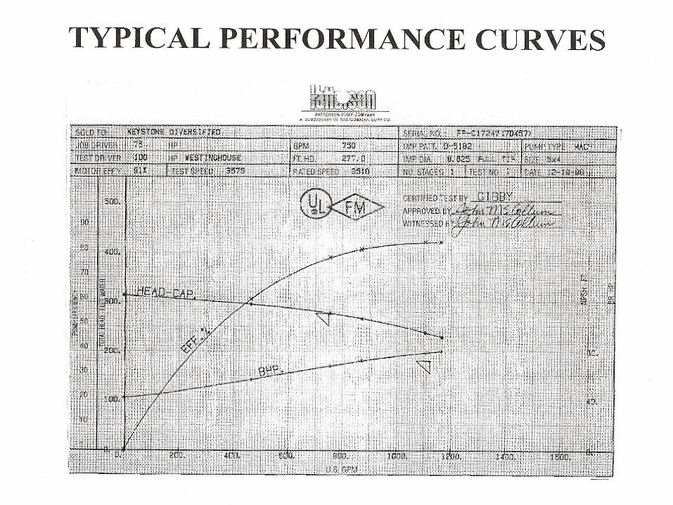
FIRE PUMPS
FIRE PUMPS
General A centrifugal pump for fire protection shall be
selected to operate at less than or equal to 150% of the rated capacity. The pump should be selected at capacities between 90% to 140% of the rated capacity( clause 5.8.1 ).
It is a poor design practice to overdesign the fire pump and the driver and depend on the pressure relief valve to open and relieve the excess pressure
Requirements of Pump room
Indoor fire pump units should be physically separated or protected by fire rated construction. For a fully sprinklered pump room one hour fire rating is required.
Emergency lighting and ventilation are required in pump room.
Drainage-Flow should be pitched to adequate drainage of escaping water from pump and other accessories.
Piping
Steel pipe should be used for above ground applications. For underground applications NFPA 24 should be followed.
Steel pipes should be joined by means of threaded, flanged (flanges welded to pipes are preferred), grooved joints.

Suction piping
The size of the suction pipe for a single pump or of the suction header pipe for multiple pumps ( operating together) should be such that with all pumps operating at 150% of the rated capacity, the gauge pressure at the pump suction flanges should be 0 bar or higher.
Where the supply is the suction tank with its base at or above the same elevation as the pump gauge, pressure at the pump suction flange shall be permitted to drop to -0.2 bar.
Suction piping………cont’d
Suction pipe should be sized such that with the pumps operating at 150% of the rated capacity, the velocity in that portion of the suction pipe located within 10 pipe diameters upstream of the suction flange does not exceed 4.57m/s and the size should not be less than that specified in section 5.25
A listed OS&Y gate valve should be installed in the suction pipe.

Suction piping………cont’d
No valve other than a listed OS&Y valve should be installed in the suction pipe within 15.3m.
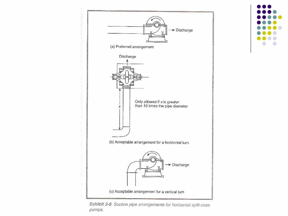
Elbows and Tees with a centre line plane parallel to HSC pump are not permitted within 10 times the suction pipe diameter.
Elbows with centre line plane perpendicular to HSC pump shaft is permitted.
Where the pump and water tank are on separate foundations provision shall be made for strain relief.
Suction piping………cont’d
For pumps taking suction from a water tank a vortex plate shall be provided at the entrance to the suction pipe.
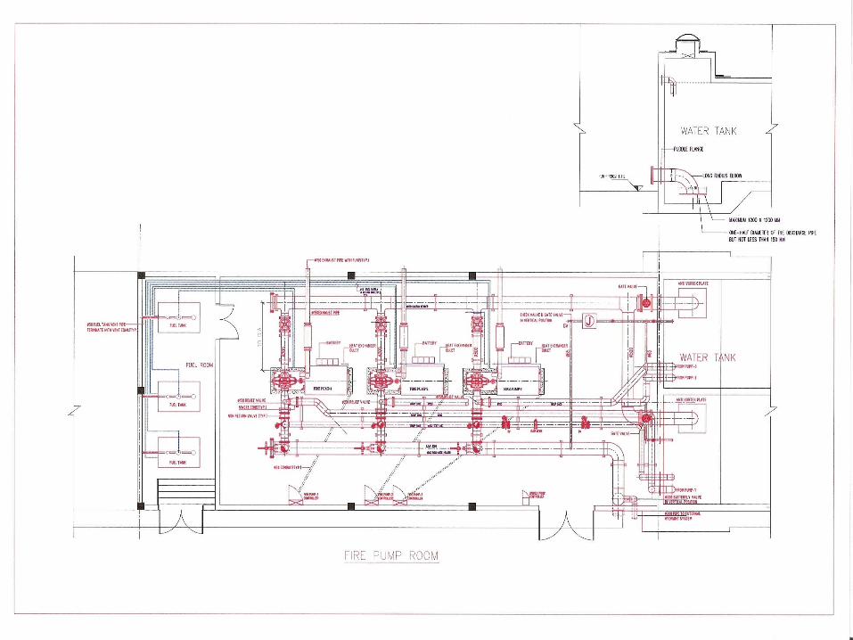
Discharge piping The size of the pump discharge pipe should not be
less than that given in section 5.25 Flanges welded to pipes are preferred. Butterfly valves are permitted. No pressure regulating devices should be installed
in the discharge pipe except as permitted in NFPA 20.
Pressure relief valves are required for diesel engine pumps only if the 121% of the shut off head + static suction pressure exceeds the system components rating.
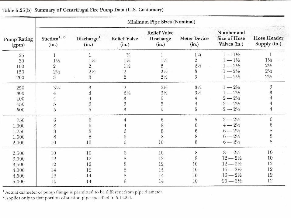
Discharge piping………..cont’d Size of the relief valve should be as per section 5.25 Relief valve should be located between check valve
and the pump. Relief valve discharge piping returning water back to
the storage tank should be piped independently and not be combined with the discharge from other relief valves.
Flow meter-size of the test line and flow meter should be as per section 5.25

Jockey pump
Flow rate of a jockey pump should not be less than the normal leakage rate.
Jockey pump should be sized to make up the allowable leakage rate within 10 minutes or 3.8 litres/min which ever is larger.
For sprinkler systems jockey pumps are generally sized to flow an amount of water less than or equal to that required by a single sprinkler.
Centrifugal Pumps Centrifugal pumps shall not be used where a static
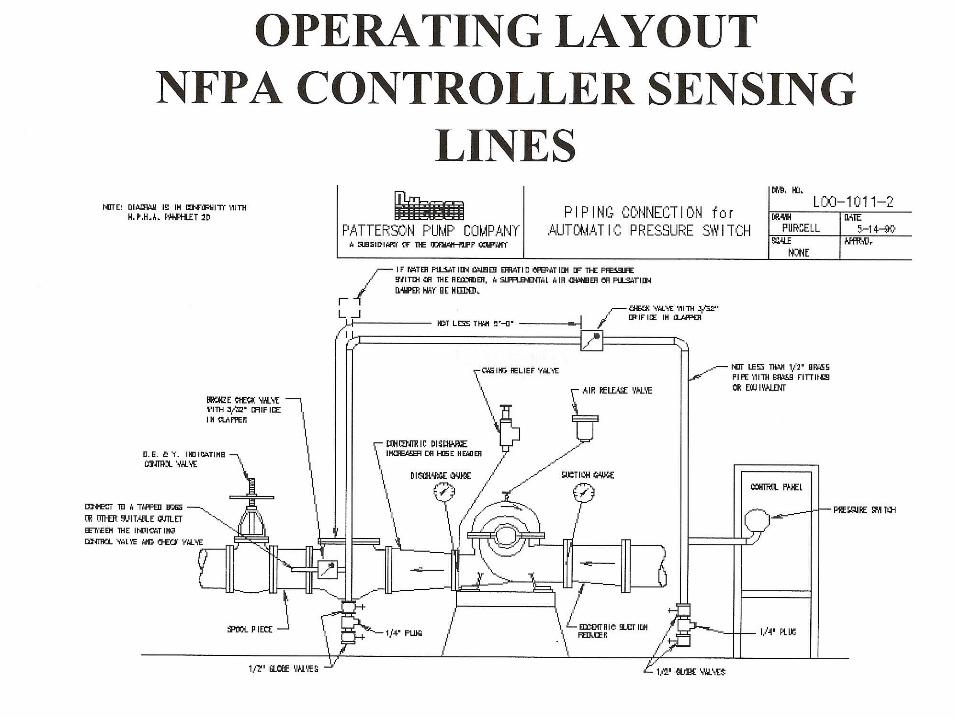
suction lift is required. Fittings (accessories) to be provided by the
manufacturer or an authorised representative.
1.Automatic air release valve
2.Circulation relief valve
3.Pressure gauges Strainer:-Pumps that require removal of the driver to
remove rocks or debris from the pump impeller should have a pipe lined strainer installed in the suction line a minimum of 10 pipe diameters from the suction flange.
Centrifugal Pumps………cont’d
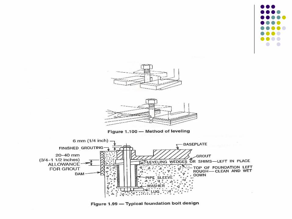
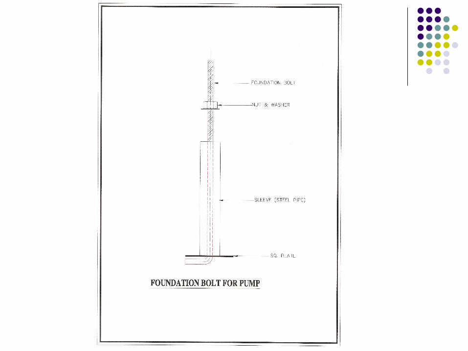
Foundation:-The base plate of the pump should be securely attached to the solid foundation.
The foundation should be sufficiently substantial to form a permanent and rigid support for the base plate.
Vertical shaft turbine pumps
Wet Pit Installation The required submergence should be obtained from
the pump manufacturer.


Electric drive for pumps
For pumps driven by electric motors where a reliable power cannot be obtained from reliable power sources , one of the following arrangements should be provided.
Combination of two or more power sources One of the approved power sources and an onsite
standby generator. An approved combination of feeders constituting two
or more power sources.
Electric drive for pumps…cont’d
Combination of one or feeders in combination with an onsite standby generator
One of the power source and a redundant fire pump driven by diesel engine.
Transfer of power to the fire pump controller between normal power supply and one alternate power supply should take place within the pump room.

Fire pump’s controller (Electric)Primary Design System operation is Primary Protection of connected motor is secondary
Fire pump’s controller (Electric)………….cont’d
Controllers should be located as close as is practical to the motors they control and should be within the site of the motors.
Interfacing with fire alarm system.Pump runningLoss of PhasePhase reversalController connected to alternate power supply.
Emergency Starting Circuits
If the contactor coil does not function for any reason an emergency mechanical means is available for closing the contactor
Service Entrance Rating
Utility can DIRECTLY connect to controller Equipped with grounding lug bonded to the
enclosure For added safety controller equipped with
isolating switch interlocked with enclosure door.
Motor Contactor
No control circuit fuse No voltage, frequency or other sensor to
prevent operation of contactor No thermal overload relay Contactor coil at LINE voltage
Circuit Breaker
Maintains locked rotor current for: 8 Seconds Minimum 20 Seconds Maximum LRC=600% of Motor FLA
Minimum setting is 300% of the motor’s full load Amps for 30 minutes minimum
Circuit Breaker Type
Magnetic device only No thermal elements are permitted Instantaneous Reset
Circuit Breaker Basic Design
Set to allow operation, not to protect the connected electric motor
All motors shall be specifically listed for fire pump service
Horsepower and locked rotor current motor designation shall be as per NEC & NFPA 70 National Electric Code
All motors shall comply with NEMA standard MG-1 and be marked as complying with NEMA Design B standards
All motors shall be rated for continuous duty and shall be applied only at voltages of +10 percent of the motor nameplate voltage.
Electric-motor-induced transients shall be coordinated with 7-4.3.3 to prevent nuisance tripping of motor controller protective devices.
Diesel Engine
Fuel Supply and arrangement
Fuel tank should have a capacity at least 1 gal/hp, plus 5% volume for expansion and 5% volume for sump
For multiple diesel engine pumps, separate fuel line and separate fuel tank are required.
Inlet to the fuel supply line should be located so that its opening is no lower than the level of the engine fuel pump.
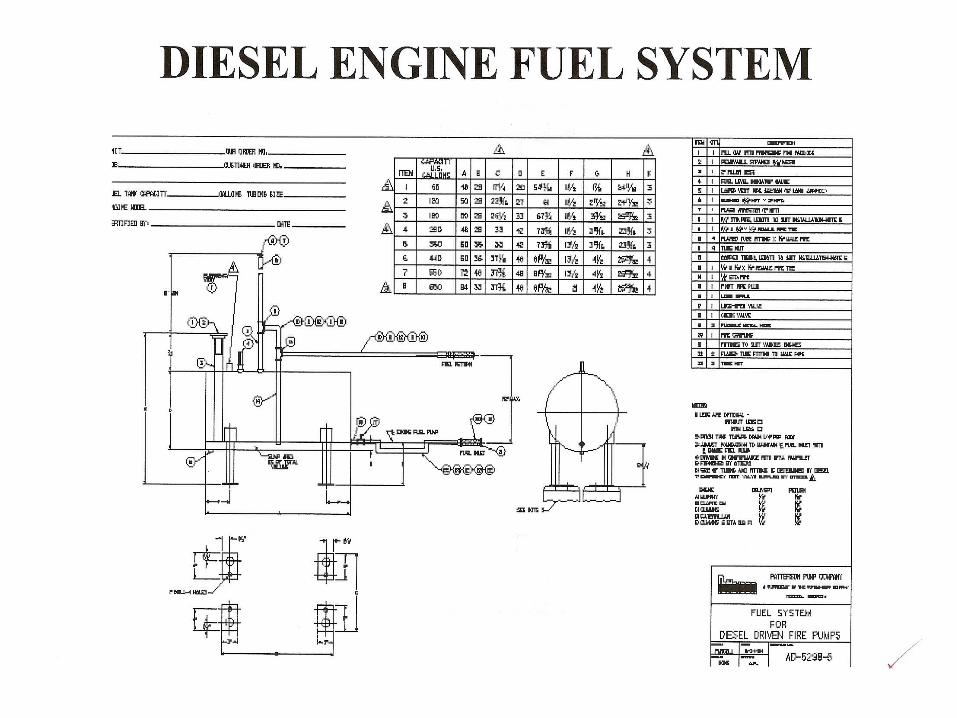
Diesel Engine…..cont’d
The engine manufacturer’s fuel pump static head pressure limit should not be exceeded.
Galvanised steel or copper should not be used for fuel piping
No shutoff valve should be installed in the fuel return line to the tank.
Air supply and discharge ventilators should be provided.
Controller for Diesel Engine
System operation is primary Protection of the connected engine is
secondary
Engine Protection Circuits
Allows engine to continue operation: When a low oil pressure condition exists When a high cooling water temperature
condition exists.