Portable Fire Pumps - Astra Security Portable Fire Pumps Leaflet.pdf · led some fire services to...
12
Portable Fire Pumps
-
Upload
nguyenmien -
Category
Documents
-
view
233 -
download
1
Transcript of Portable Fire Pumps - Astra Security Portable Fire Pumps Leaflet.pdf · led some fire services to...
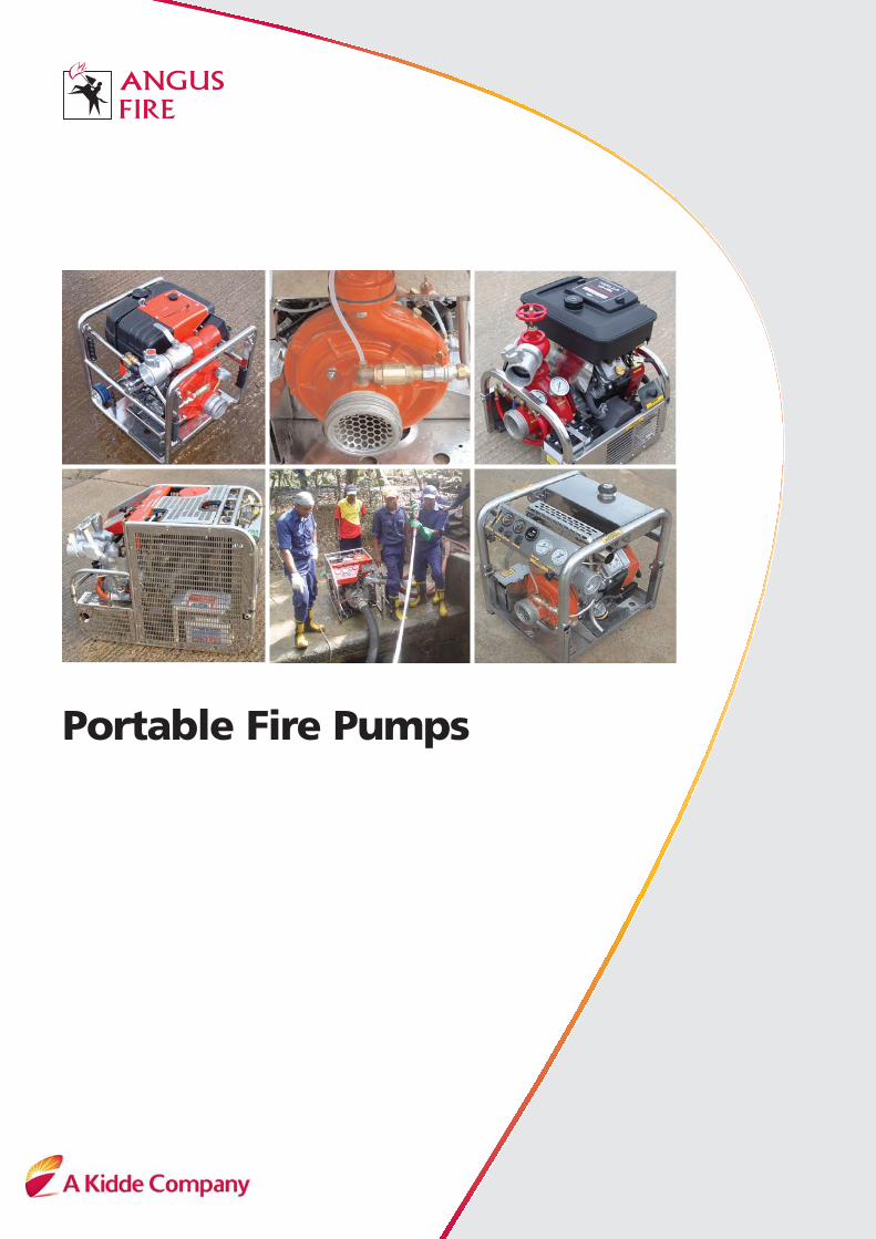
Portable Fire Pumps
Self-contained portable fire
fighting pumps are an essential
tool for modern fire fighters.
Advances in air-cooled engines,
materials and pump technology
have transformed the modern
pump into a reliable and
practical tool for the
professionally equipped fire and
rescue service.
Fire pumps must not only
deliver pressure and flow while
being portable and easy to use,
but must also meet world wide
regulations governing exhaust
emissions and sound levels.
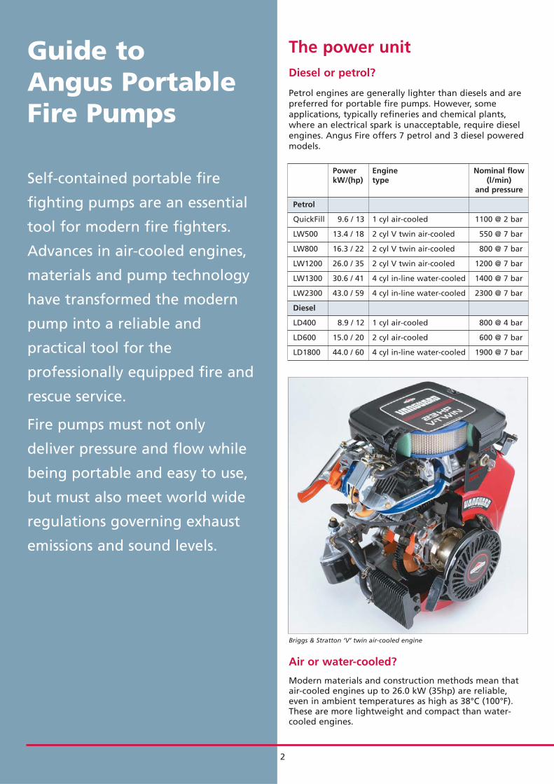
The power unitDiesel or petrol?
Petrol engines are generally lighter than diesels and arepreferred for portable fire pumps. However, someapplications, typically refineries and chemical plants,where an electrical spark is unacceptable, require dieselengines. Angus Fire offers 7 petrol and 3 diesel poweredmodels.
Power Engine Nominal flowkW/(hp) type (l/min)
and pressure
Petrol
QuickFill 9.6 / 13 1 cyl air-cooled 1100 @ 2 bar
LW500 13.4 / 18 2 cyl V twin air-cooled 550 @ 7 bar
LW800 16.3 / 22 2 cyl V twin air-cooled 800 @ 7 bar
LW1200 26.0 / 35 2 cyl V twin air-cooled 1200 @ 7 bar
LW1300 30.6 / 41 4 cyl in-line water-cooled 1400 @ 7 bar
LW2300 43.0 / 59 4 cyl in-line water-cooled 2300 @ 7 bar
Diesel
LD400 8.9 / 12 1 cyl air-cooled 800 @ 4 bar
LD600 15.0 / 20 2 cyl air-cooled 600 @ 7 bar
LD1800 44.0 / 60 4 cyl in-line water-cooled 1900 @ 7 bar
Guide to Angus PortableFire Pumps
Air or water-cooled?
Modern materials and construction methods mean thatair-cooled engines up to 26.0 kW (35hp) are reliable,even in ambient temperatures as high as 38°C (100°F).These are more lightweight and compact than water-cooled engines.
Briggs & Stratton ‘V’ twin air-cooled engine
2
Electrical or manual starting?
Modern electric starters and batteries ensure a firsttime start capability close to 100%. In the unlikelyevent of battery failure it is possible to provide amanual start facility on smaller pumps, but it is notgenerally practical to pull start any engine over 26.0 kW (35hp).
All Angus fire pumps, apart from the smallest model,incorporate electric start from an onboard battery. In addition, all pumps, up to and including the 30.6 kW (41 hp) LW1300, incorporate a manual pullhand start. However, some modern engines cannot bestarted manually, even when fitted with a magneto, ifa charged battery is absent. This can be critical in anemergency. All Angus hand start engines can be pullstarted even when the battery is not present.
Electrical systems12V electrical systems are standard on all Anguspumps and most engines are supplied with both amagneto (to provide high tension electricity for thespark) and an alternator (to provide current at 12V forbattery charging and powering accessories).
Most Angus pumps are provided with a standardsocket to accept a battery charging input for use whilethe pump is stored and to provide a source of 12V DCelectricity to power accessories when the pump isrunning.
All Angus pump electrical systems are designed tooperate even when the pump is subjected to intensewater spray.
Sound levelsEuropean regulation EN 12100-2 specifies two levels ofcontrol which relate directly to portable pumps:
Above 80 dB Hearing protection must be available
Above 90 dB Hearing protection must be worn andwarnings must be posted indicating the area where sound levels above 90 dB can be experienced
Sound level Engine Compliance withEN 12100-2
Petrol
QuickFill 89 dB @ 3 bar Air-cooled �
LW500 89 dB @ 6 bar Air-cooled �
LW800 87 dB @ 6 bar Air-cooled �
LW1300 98 dB @ 6 bar Water-cooled �
LW2300 102 dB @ 7 bar Water-cooled �
Diesel
LD400 95 dB @ 3 bar Air-cooled �
LD600 98 dB @ 3 bar Air-cooled �
LD1800 108 dB @ 7 bar Water-cooled �
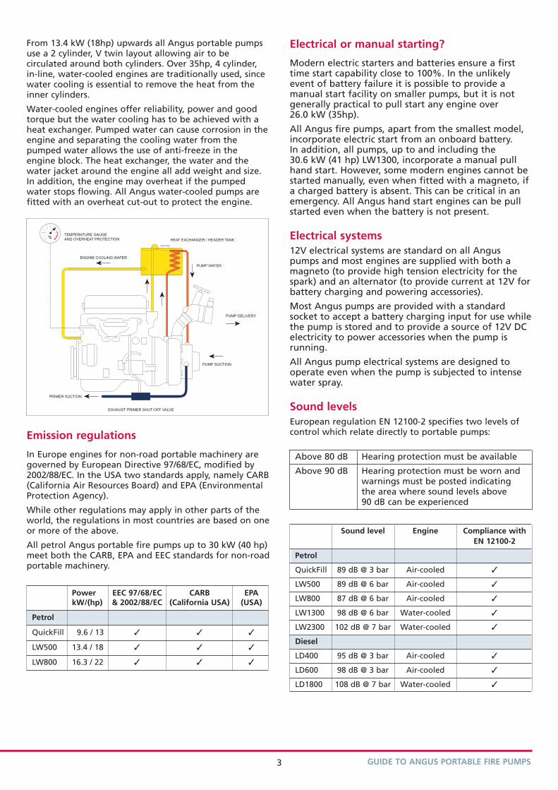
From 13.4 kW (18hp) upwards all Angus portable pumpsuse a 2 cylinder, V twin layout allowing air to becirculated around both cylinders. Over 35hp, 4 cylinder,in-line, water-cooled engines are traditionally used, sincewater cooling is essential to remove the heat from theinner cylinders.
Water-cooled engines offer reliability, power and goodtorque but the water cooling has to be achieved with aheat exchanger. Pumped water can cause corrosion in theengine and separating the cooling water from thepumped water allows the use of anti-freeze in theengine block. The heat exchanger, the water and thewater jacket around the engine all add weight and size.In addition, the engine may overheat if the pumpedwater stops flowing. All Angus water-cooled pumps arefitted with an overheat cut-out to protect the engine.
Emission regulations
In Europe engines for non-road portable machinery aregoverned by European Directive 97/68/EC, modified by2002/88/EC. In the USA two standards apply, namely CARB(California Air Resources Board) and EPA (EnvironmentalProtection Agency).
While other regulations may apply in other parts of theworld, the regulations in most countries are based on oneor more of the above.
All petrol Angus portable fire pumps up to 30 kW (40 hp)meet both the CARB, EPA and EEC standards for non-roadportable machinery.
HEAT EXCHANGER / HEADER TANK
ENGINE COOLING WATER
PRIMER SUCTION
TEMPERATURE GAUGE
AND OVERHEAT PROTECTIONoC
PUMP WATER
PUMP DELIVERY
PUMP SUCTION
EXHAUST PRIMER SHUT-OFF VALVE
Power EEC 97/68/EC CARB EPAkW/(hp) & 2002/88/EC (California USA) (USA)
Petrol
QuickFill 9.6 / 13 � � �
LW500 13.4 / 18 � � �
LW800 16.3 / 22 � � �
GUIDE TO ANGUS PORTABLE FIRE PUMPS3
Pump construction
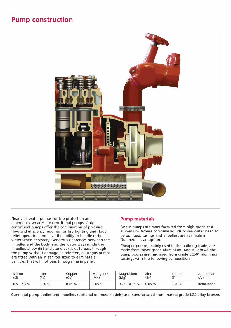
Nearly all water pumps for fire protection andemergency services are centrifugal pumps. Onlycentrifugal pumps offer the combination of pressure,flow and efficiency required for fire fighting and floodrelief operation and have the ability to handle dirtywater when necessary. Generous clearances between theimpeller and the body, and the water ways inside theimpeller, allow dirt and stone particles to pass throughthe pump without damage. In addition, all Angus pumpsare fitted with an inlet filter sized to eliminate allparticles that will not pass through the impeller.
Pump materials
Angus pumps are manufactured from high grade castaluminium. Where corrosive liquids or sea water need tobe pumped, casings and impellers are available inGunmetal as an option.
Cheaper pumps, mainly used in the building trade, aremade from lower grade aluminium. Angus lightweightpump bodies are machined from grade CC601 aluminiumcastings with the following composition:
Silicon Iron Copper Manganese Magnesium Zinc Titanium Aluminium (Si) (Fe) (Cu) (Mn) (Mg) (Zn) (Ti) (Al)
6.5 – 7.5 % 0.20 % 0.05 % 0.05 % 0.25 – 0.35 % 0.05 % 0.20 % Remainder
Gunmetal pump bodies and impellers (optional on most models) are manufactured from marine grade LG2 alloy bronze.
4
GUIDE TO ANGUS PORTABLE FIRE PUMPS
Priming
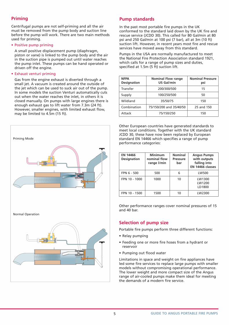
Centrifugal pumps are not self-priming and all the airmust be removed from the pump body and suction linebefore the pump will work. There are two main methodsused for priming.
• Positive pump priming
A small positive displacement pump (diaphragm,piston or vane) is linked to the pump body and the airin the suction pipe is pumped out until water reachesthe pump inlet. These pumps can be hand operated ordriven off the engine.
• Exhaust venturi priming
Gas from the engine exhaust is diverted through asmall jet. A vacuum is created around the outside ofthe jet which can be used to suck air out of the pump.In some models the suction Venturi automatically cutsout when the water reaches the inlet, in others it isclosed manually. On pumps with large engines there isenough exhaust gas to lift water from 7.3m (24 ft).However, smaller engines, with limited exhaust flow,may be limited to 4.5m (15 ft).
Priming Mode
Normal Operation
Pump standards
In the past most portable fire pumps in the UKconformed to the standard laid down by the UK fire andrescue service (JCDD 30). This called for 80 Gal/min at 80psi and 250 Gal/min at 100 psi (7 bar), all at 3m (10 ft)suction lift. However, in recent years most fire and rescueservices have moved away from this standard.
Pumps in the USA are normally manufactured to meetthe National Fire Protection Association standard 1921,which calls for a range of pump sizes and duties,specified at 1.5m (5 ft) suction lift.
NFPA Nominal Flow range Nominal PressureDesignation US Gal/min psi
Transfer 200/300/500 15
Supply 100/250/500 50
Wildland 35/50/75 150
Combination 75/150/200 and 35/40/50 25 and 150
Attack 75/150/250 150
Other European countries have generated standards tomeet local conditions. Together with the UK standardJCDD 30, these have now been replaced by Europeanstandard EN 14466 which specifies a range of pumpperformance categories:
EN 14466 Minimum Nominal Angus PumpsDesignation nominal flow Pressure with outputs
range l/min bar falling intoEN 14466 classes
FPN 6 - 500 500 6 LW500
FPN 10 - 1000 1000 10 LW1300LW1200LD1800
FPN 10 - 1500 1500 10 LW2300
Other performance ranges cover nominal pressures of 15and 40 bar.
Selection of pump sizePortable fire pumps perform three different functions:
• Relay pumping
• Feeding one or more fire hoses from a hydrant orreservoir
• Pumping out flood water
Limitations in space and weight on fire appliances haveled some fire services to replace large pumps with smallermodels without compromising operational performance.The lower weight and more compact size of the Angusrange of air-cooled pumps make them ideal for meetingthe demands of a modern fire service.
5
SUCTION
Salvage applications
In salvage applications, such as pumping out a cellar,supply pressure is not critical.
The predicted time taken for three different sizes ofpump to clear a cellar 4m x 3m x 3m deep containing36,000 litres of water is compared below:
Pump casing pressure capability
Pumps only intended for building work are usuallydesigned for the inlet to be at less than 1 bar (suctioncondition). These pumps will not withstand a largepositive inlet pressure from a hydrant or relay pump.
Time to pump dry
LW1300 19 min
LW800 12 min
LW500 17 min
Inlet pressure Flow Added Outletcondition pump pressure pressure
-0.3 bar Pump (3m suction lift) design flow 7.0 bar 6.7 bar
+4.0 bar (from Pump hydrant or relay) design flow 7.0 bar 11.0 bar
+4.0 bar (from Blocked hydrant or relay) outlet 11.0 bar 15.0 bar
When specifying a pump for fire duty where there maybe a positive inlet pressure it is essential the pumpcasing is pressure rated accordingly.
All Angus pump bodies are tested to withstand 20 barpressure (maximum working pressure 13.3 bar).
Number of hoses that can be supplied at one time
2.0 bar positive inlet pressure@ 220 l/min @ 400 l/minper nozzle per nozzle
LW1300 7 4
LW800 4 2
LW500 3 2
3m suction lift
LW1300 6 3
LW800 4 2
LW500 2 1
Fire hose operation from hydrant orreservoir
The number of hoses available from a single pump variesaccording to the inlet pressure. For an outlet pressure of7 bar, the following number of hoses can be operatedsimultaneously:
6
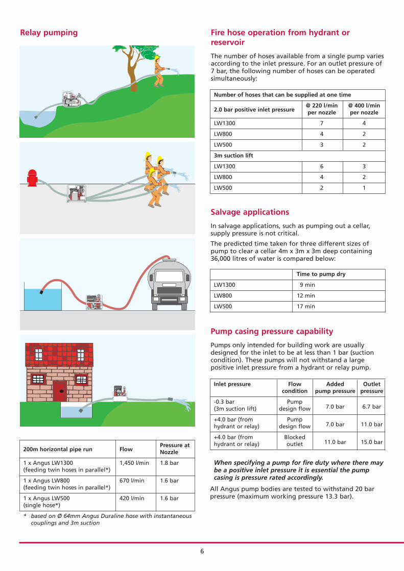
Relay pumping
200m horizontal pipe run FlowPressure atNozzle
1 x Angus LW1300 1,450 l/min 1.8 bar(feeding twin hoses in parallel*)
1 x Angus LW800 670 l/min 1.6 bar(feeding twin hoses in parallel*)
1 x Angus LW500 420 l/min 1.6 bar(single hose*)
* based on Ø 64mm Angus Duraline hose with instantaneouscouplings and 3m suction
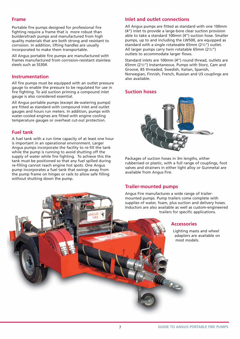
Frame
Portable fire pumps designed for professional firefighting require a frame that is more robust thanbuilders/trash pumps and manufactured from highquality materials that are both strong and resistant tocorrosion. In addition, lifting handles are usuallyincorporated to make them transportable.
All Angus portable fire pumps are manufactured withframes manufactured from corrosion-resistant stainlesssteels such as SS304.
InstrumentationAll fire pumps must be equipped with an outlet pressuregauge to enable the pressure to be regulated for use infire fighting. To aid suction priming a compound inletgauge is also considered essential.
All Angus portable pumps (except de-watering pumps)are fitted as standard with compound inlet and outletgauges and hours run meters. In addition, pumps withwater-cooled engines are fitted with engine coolingtemperature gauges or overheat cut-out protection.
Fuel tankA fuel tank with a run time capacity of at least one houris important in an operational environment. LargerAngus pumps incorporate the facility to re-fill the tankwhile the pump is running to avoid shutting off thesupply of water while fire fighting. To achieve this thetank must be positioned so that any fuel spilled duringre-filling cannot reach engine hot spots. One Anguspump incorporates a fuel tank that swings away fromthe pump frame on hinges or rails to allow safe fillingwithout shutting down the pump.
GUIDE TO ANGUS PORTABLE FIRE PUMPS
Inlet and outlet connectionsAll Angus pumps are fitted as standard with one 100mm(4”) inlet to provide a large-bore clear suction provisionable to take a standard 100mm (4”) suction hose. Smallerpumps, up to and including the LW500, are equipped asstandard with a single rotateable 65mm (21/2”) outlet. All larger pumps carry twin rotatable 65mm (21/2”)outlets to accommodate larger flows.
Standard inlets are 100mm (4”) round thread, outlets are65mm (21/2”) Instantaneous. Pumps with Storz, Cam andGroove, BS threaded, Swedish, Italian, Spanish,Norwegian, Finnish, French, Russian and US couplings arealso available.
Suction hoses
Packages of suction hoses in 3m lengths, eitherrubberised or plastic, with a full range of couplings, footvalves and strainers in either light alloy or Gunmetal areavailable from Angus Fire.
Trailer-mounted pumpsAngus Fire manufactures a wide range of trailer-mounted pumps. Pump trailers come complete withsupplies of water, foam, plus suction and delivery hoses.Inductors are also available as well as custom-engineered
trailers for specific applications.
AccessoriesLighting masts and wheeladapters are available onmost models.
7
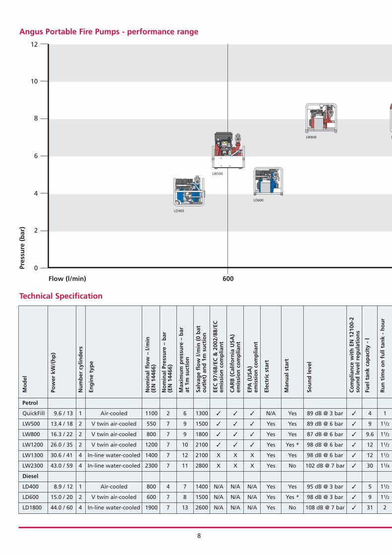
Technical Specification
Petrol
QuickFill 9.6 / 13 1 Air-cooled 1100 2 6 1300 � � � N/A Yes 89 dB @ 3 bar � 4 1
LW500 13.4 / 18 2 V twin air-cooled 550 7 9 1500 � � � Yes Yes 89 dB @ 6 bar � 9 11/2
LW800 16.3 / 22 2 V twin air-cooled 800 7 9 1800 � � � Yes Yes 87 dB @ 6 bar � 9.6 11/2
LW1200 26.0 / 35 2 V twin air-cooled 1200 7 10 2100 � � � Yes Yes * 98 dB @ 6 bar � 12 11/2
LW1300 30.6 / 41 4 In-line water-cooled 1400 7 12 2100 X X X Yes Yes 98 dB @ 6 bar � 12 11/2
LW2300 43.0 / 59 4 In-line water-cooled 2300 7 11 2800 X X X Yes No 102 dB @ 7 bar � 30 11/4
Diesel
LD400 8.9 / 12 1 Air-cooled 800 4 7 1400 N/A N/A N/A Yes Yes 95 dB @ 3 bar � 5 11/2
LD600 15.0 / 20 2 V twin air-cooled 600 7 8 1500 N/A N/A N/A Yes Yes * 98 dB @ 3 bar � 9 11/2
LD1800 44.0 / 60 4 In-line water-cooled 1900 7 13 2600 N/A N/A N/A Yes No 108 dB @ 7 bar � 31 2
Mo
del
Pow
er k
W/(
hp
)
Nu
mb
er c
ylin
der
s
Eng
ine
typ
e
No
min
al f
low
– l/
min
(E
N 1
4466
)
No
min
al P
ress
ure
– b
ar
(EN
144
66)
Max
imu
m p
ress
ure
– b
ar
at 1
m s
uct
ion
Salv
age
flo
w l/
min
(0
bat
ou
tlet
) an
d 1
m s
uct
ion
EEC
97/
68/E
C &
200
2/88
/EC
emis
sio
n c
om
plia
nt
CA
RB
(C
alif
orn
ia U
SA)
emis
sio
n c
om
plia
nt
EPA
(U
SA)
emis
sio
n c
om
plia
nt
Elec
tric
sta
rt
Man
ual
sta
rt
Sou
nd
leve
l
Co
mp
lian
ce w
ith
EN
121
00-2
sou
nd
leve
l reg
ula
tio
ns
Fuel
tan
k ca
pac
ity
- l
Ru
n t
ime
on
fu
ll ta
nk
- h
ou
r
8
Angus Portable Fire Pumps - performance range
12
10
8
6
4
2
0Pres
sure
(b
ar)
Flow (l/min) 600
LW500
LD400
LD600
LW800 L

GUIDE TO ANGUS PORTABLE FIRE PUMPS
x Manual 26 7.0 14 550 500 575 58 x x x x x x x x � � x � 1 (R) �
x Exhaust 26 4.5 10 540 500 600 74 � � x x x x x � � � � � 1 (R) �
� Exhaust 24 5.0 10 590 495 610 93 � � � � x � x � � � � � 2 �
� Exhaust 19 7.0 13 750 500 620 123 � � � � x � x � � � � � 2 �
� Exhaust 12 7.3 12 745 510 635 117 � � O O � x � � � � � � 2 �
x Exhaust 12 7.3 11 975 610 735 227 � � O O � � � � � � � � 2 �
� Exhaust 25 4.5 12 590 530 610 104 � � x x x x x x N/A � � � 1 (R) �
� Exhaust 25 5.0 10 540 500 600 83 � � x x x � x � N/A � � � 2 �
x Exhaust 10 7.3 16 1030 610 740 259 � � O O � x � � � � � � 2 �
* Emergency use only ** Including oil, cooling water and battery where applicable (R) Rotatable (O) Optional
Re-
fill
du
rin
g o
per
atio
n
Prim
ing
sys
tem
Tim
e to
pri
me
to 3
m -
sec
on
d
Max
imu
m p
rim
ing
lift
(m
)
Max
imu
m s
ize
of
solid
ab
le t
op
ass
thro
ug
h p
um
p (
mm
)
Ove
rall
len
gth
(m
m)
Ove
rall
wid
th (
mm
)
Ove
rall
hei
gh
t (m
m)
Wei
gh
t –
kg (
fully
op
erat
ion
al
wit
h f
ull
fuel
tan
k) *
*
Inle
t co
mp
ou
nd
gau
ge
– b
ar(g
lyce
rin
e fi
lled
)
Ou
tlet
pre
ssu
re g
aug
e –
bar
(gly
ceri
ne
fille
d)
Oil
pre
ssu
re g
aug
e
Bat
tery
ch
arg
e g
aug
e
Ove
rhea
tin
g w
arn
ing
/ c
ut
ou
t
Fuel
gau
ge
Tem
per
atu
re g
aug
e /
war
nin
g li
gh
t
Ho
ur
run
met
er
Ch
arg
ing
/ a
uxi
liary
ele
ctri
cal
po
wer
so
cket
Mar
ine
ligh
t al
loy
pu
mp
bo
dy
and
imp
elle
r
Op
tio
nal
gu
nm
etal
pu
mp
bo
dy
and
Imp
elle
r
Inle
t 10
0mm
(4”
) B
SP R
ou
nd
Nu
mb
er o
utl
ets
– 65
mm
(21
/2”)
inst
anta
neo
us
Sto
rz c
ou
plin
gs
avai
lab
le
9
1200 1800 2400
QUICKFILL
LW1200
LW1300
LD1800
LW2300
10
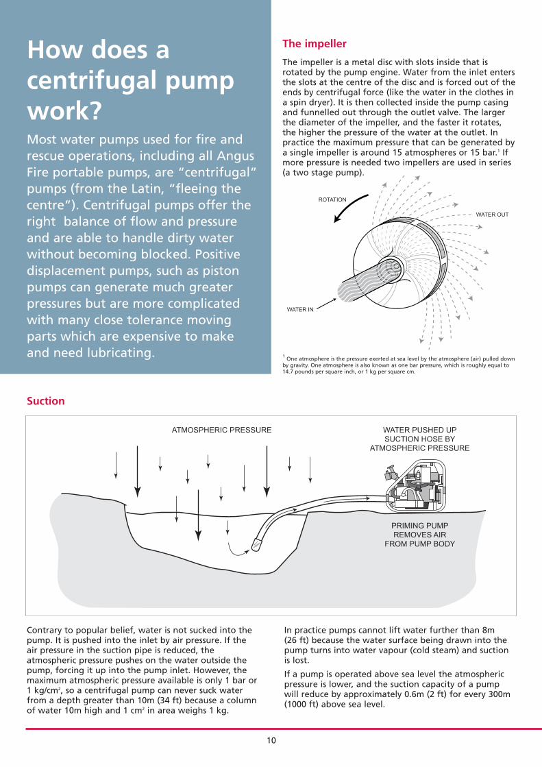
ROTATION
WATER IN
WATER OUT
The impeller
The impeller is a metal disc with slots inside that isrotated by the pump engine. Water from the inlet entersthe slots at the centre of the disc and is forced out of theends by centrifugal force (like the water in the clothes ina spin dryer). It is then collected inside the pump casingand funnelled out through the outlet valve. The largerthe diameter of the impeller, and the faster it rotates,the higher the pressure of the water at the outlet. Inpractice the maximum pressure that can be generated bya single impeller is around 15 atmospheres or 15 bar.1 Ifmore pressure is needed two impellers are used in series(a two stage pump).
How does acentrifugal pumpwork?Most water pumps used for fire andrescue operations, including all AngusFire portable pumps, are “centrifugal”pumps (from the Latin, “fleeing thecentre”). Centrifugal pumps offer theright balance of flow and pressureand are able to handle dirty waterwithout becoming blocked. Positivedisplacement pumps, such as pistonpumps can generate much greaterpressures but are more complicatedwith many close tolerance movingparts which are expensive to makeand need lubricating. 1 One atmosphere is the pressure exerted at sea level by the atmosphere (air) pulled down
by gravity. One atmosphere is also known as one bar pressure, which is roughly equal to14.7 pounds per square inch, or 1 kg per square cm.
Suction
Contrary to popular belief, water is not sucked into thepump. It is pushed into the inlet by air pressure. If theair pressure in the suction pipe is reduced, theatmospheric pressure pushes on the water outside thepump, forcing it up into the pump inlet. However, themaximum atmospheric pressure available is only 1 bar or1 kg/cm2, so a centrifugal pump can never suck waterfrom a depth greater than 10m (34 ft) because a columnof water 10m high and 1 cm2 in area weighs 1 kg.
In practice pumps cannot lift water further than 8m (26 ft) because the water surface being drawn into thepump turns into water vapour (cold steam) and suctionis lost.
If a pump is operated above sea level the atmosphericpressure is lower, and the suction capacity of a pumpwill reduce by approximately 0.6m (2 ft) for every 300m(1000 ft) above sea level.
ATMOSPHERIC PRESSURE
PRIMING PUMP
REMOVES AIR
FROM PUMP BODY
WATER PUSHED UP
SUCTION HOSE BY
ATMOSPHERIC PRESSURE
GUIDE TO ANGUS PORTABLE FIRE PUMPS
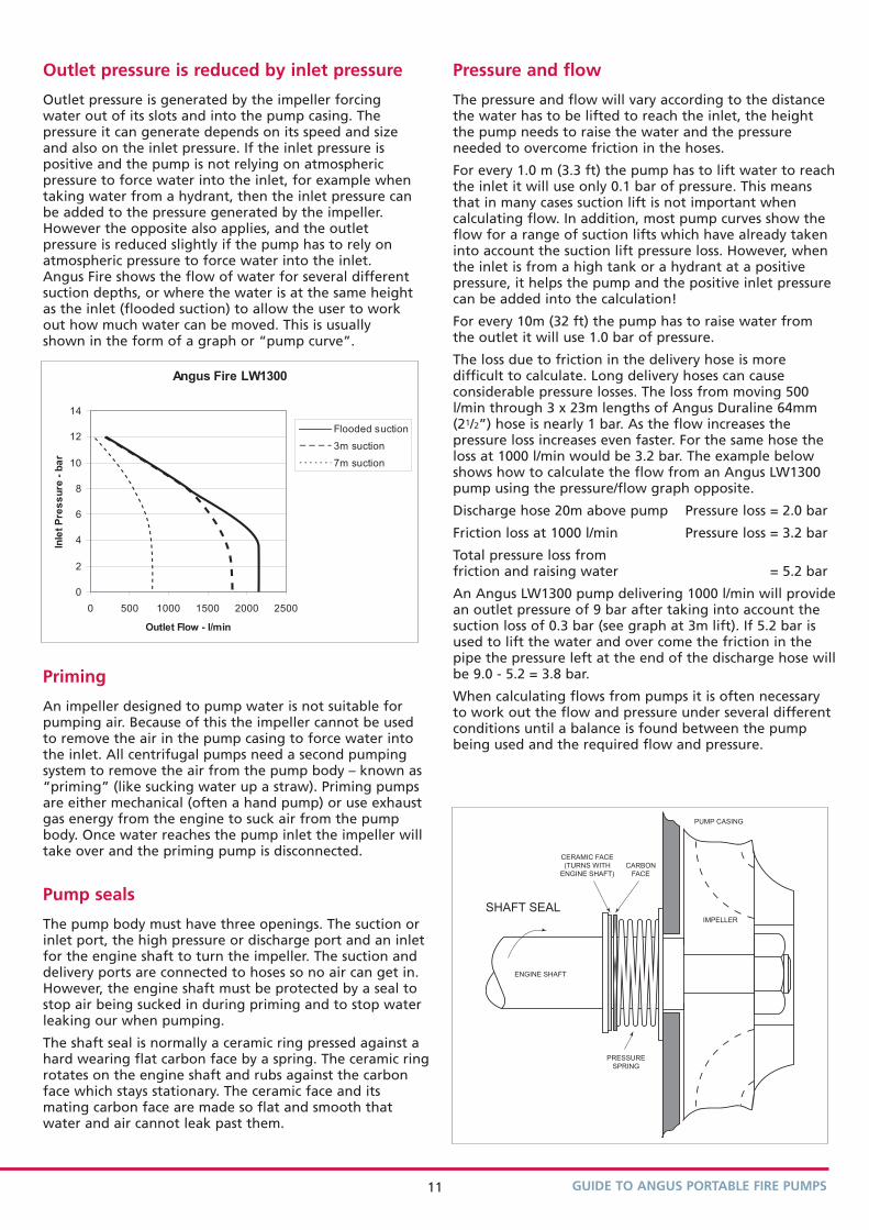
Outlet pressure is reduced by inlet pressure
Outlet pressure is generated by the impeller forcingwater out of its slots and into the pump casing. Thepressure it can generate depends on its speed and sizeand also on the inlet pressure. If the inlet pressure ispositive and the pump is not relying on atmosphericpressure to force water into the inlet, for example whentaking water from a hydrant, then the inlet pressure canbe added to the pressure generated by the impeller.However the opposite also applies, and the outletpressure is reduced slightly if the pump has to rely onatmospheric pressure to force water into the inlet.Angus Fire shows the flow of water for several differentsuction depths, or where the water is at the same heightas the inlet (flooded suction) to allow the user to workout how much water can be moved. This is usuallyshown in the form of a graph or “pump curve”.
Angus Fire LW1300
0
2
4
6
8
10
12
14
0 500 1000 1500 2000 2500
Outlet Flow - l/min
Inle
t P
res
su
re -
ba
r
Flooded suction
3m suction
7m suction
Priming
An impeller designed to pump water is not suitable forpumping air. Because of this the impeller cannot be usedto remove the air in the pump casing to force water intothe inlet. All centrifugal pumps need a second pumpingsystem to remove the air from the pump body – known as“priming” (like sucking water up a straw). Priming pumpsare either mechanical (often a hand pump) or use exhaustgas energy from the engine to suck air from the pumpbody. Once water reaches the pump inlet the impeller willtake over and the priming pump is disconnected.
Pump seals
The pump body must have three openings. The suction orinlet port, the high pressure or discharge port and an inletfor the engine shaft to turn the impeller. The suction anddelivery ports are connected to hoses so no air can get in.However, the engine shaft must be protected by a seal tostop air being sucked in during priming and to stop waterleaking our when pumping.
The shaft seal is normally a ceramic ring pressed against ahard wearing flat carbon face by a spring. The ceramic ringrotates on the engine shaft and rubs against the carbonface which stays stationary. The ceramic face and itsmating carbon face are made so flat and smooth thatwater and air cannot leak past them.
IMPELLER
ENGINE SHAFT
PRESSURE
SPRING
SHAFT SEAL
CERAMIC FACE
(TURNS WITH
ENGINE SHAFT)
CARBON
FACE
PUMP CASING
Pressure and flow
The pressure and flow will vary according to the distancethe water has to be lifted to reach the inlet, the heightthe pump needs to raise the water and the pressureneeded to overcome friction in the hoses.
For every 1.0 m (3.3 ft) the pump has to lift water to reachthe inlet it will use only 0.1 bar of pressure. This meansthat in many cases suction lift is not important whencalculating flow. In addition, most pump curves show theflow for a range of suction lifts which have already takeninto account the suction lift pressure loss. However, whenthe inlet is from a high tank or a hydrant at a positivepressure, it helps the pump and the positive inlet pressurecan be added into the calculation!
For every 10m (32 ft) the pump has to raise water fromthe outlet it will use 1.0 bar of pressure.
The loss due to friction in the delivery hose is moredifficult to calculate. Long delivery hoses can causeconsiderable pressure losses. The loss from moving 500l/min through 3 x 23m lengths of Angus Duraline 64mm(21/2”) hose is nearly 1 bar. As the flow increases thepressure loss increases even faster. For the same hose theloss at 1000 l/min would be 3.2 bar. The example belowshows how to calculate the flow from an Angus LW1300pump using the pressure/flow graph opposite.
Discharge hose 20m above pump Pressure loss = 2.0 bar
Friction loss at 1000 l/min Pressure loss = 3.2 bar
Total pressure loss from friction and raising water = 5.2 bar
An Angus LW1300 pump delivering 1000 l/min will providean outlet pressure of 9 bar after taking into account thesuction loss of 0.3 bar (see graph at 3m lift). If 5.2 bar isused to lift the water and over come the friction in thepipe the pressure left at the end of the discharge hose willbe 9.0 - 5.2 = 3.8 bar.
When calculating flows from pumps it is often necessaryto work out the flow and pressure under several differentconditions until a balance is found between the pumpbeing used and the required flow and pressure.
11
THAME PARK ROAD, THAME, OXFORDSHIRE, OX9 3RT, ENGLAND
Tel: +44 (0)1844 265000 Fax: +44 (0)1844 265156e-mail: [email protected] Web site: www.angusfire.co.uk
REF: 6344/2-05/06 © Angus Fire Printed in England
Angus Fire reserves the right to modify any specification without prior notice.
Technical datasheets containing further information on Angus Portable Fire Pumps are available on request from your localAngus Fire representative or from our website www.angusfire.co.uk
Pressure loss in fire hose
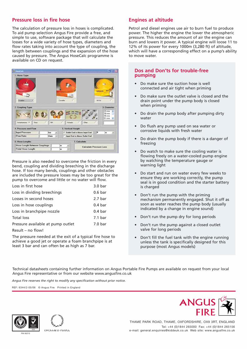
The calculation of pressure loss in hoses is complicated.To aid pump selection Angus Fire provide a free, andsimple to use, software package that will calculate thelosses for a wide variety of hose types, diameters andflow rates taking into account the type of coupling, thelength between couplings and the expansion of the hosecaused by pressure. The Angus HoseCalc programme isavailable on CD on request.
Pressure is also needed to overcome the friction in everybend, coupling and dividing breeching in the dischargehose. If too many bends, couplings and other obstaclesare included the pressure losses may be too great for thepump to overcome and little or no water will flow.
Loss in first hose 3.0 bar
Loss in dividing breechings 0.6 bar
Losses in second hoses 2.7 bar
Loss in hose couplings 0.4 bar
Loss in branchpipe nozzle 0.4 bar
Total loss 7.1 bar
Pressure available at pump outlet 7.0 bar
Result – no flow!
The pressure needed at the exit of a typical fire hose toachieve a good jet or operate a foam branchpipe is atleast 3 bar and can often be as high as 7 bar.
Dos and Don’ts for trouble-freepumping
• Do make sure the suction hose is wellconnected and air tight when priming
• Do make sure the outlet valve is closed and thedrain point under the pump body is closedwhen priming
• Do drain the pump body after pumping dirtywater
• Do flush any pump used on sea water orcorrosive liquids with fresh water
• Do drain the pump body if there is a danger offreezing
• Do watch to make sure the cooling water isflowing freely on a water-cooled pump engineby watching the temperature gauge orwarning light
• Do start and run on water every few weeks toensure they are working correctly, the pumpseal is in good condition and the starter batteryis charged
• Don’t run the pump with the primingmechanism permanently engaged. Shut it off assoon as water reaches the pump body (usuallyindicated by a change in engine sound)
• Don’t run the pump dry for long periods
• Don’t run the pump against a closed outletvalve for long periods
• Don’t fill the fuel tank with the engine runningunless the tank is specifically designed for thispurpose (most Angus models)
Engines at altitude
Petrol and diesel engines use air to burn fuel to producepower. The higher the engine the lower the atmosphericpressure. This reduces the amount of air the engine canburn and lowers it power. A typical engine will loose 11 to12% of its power for every 1000m (3,280 ft) of altitude,which will have a corresponding effect on a pump’s abilityto move water.