FIRE PROTECTION PUMPS
49
April 2012 Interim Revision October 2021 Page 1 of 49 FIRE PROTECTION PUMPS Table of Contents Page 1.0 SCOPE .................................................................................................................................................... 4 1.1 Hazards ............................................................................................................................................ 4 1.2 Changes ............................................................................................................................................ 4 2.0 LOSS PREVENTION RECOMMENDATIONS ........................................................................................ 4 2.1 Introduction ....................................................................................................................................... 4 2.2 Construction and Location ............................................................................................................... 4 2.2.1 General ................................................................................................................................... 4 2.2.2 High-Rise Buildings ................................................................................................................ 6 2.3 Protection ......................................................................................................................................... 8 2.3.1 General .................................................................................................................................... 8 2.3.2 Suction Piping ......................................................................................................................... 8 2.3.3 Discharge Piping .................................................................................................................. 11 2.3.4 Pressure Relief Valves ......................................................................................................... 11 2.3.5 Pressure Reducing Valves .................................................................................................... 13 2.4 Equipment and Processes ............................................................................................................. 13 2.4.1 Split Case, End Suction, and In-Line Centerfugal Pumps .................................................. 13 2.4.2 Vertical Shaft Turbine-Type Pumps ..................................................................................... 13 2.4.3 Positive Displacement Pumps .............................................................................................. 13 2.4.4 Mounting, Coupling, and Alignment ..................................................................................... 13 2.4.5 Mechanical Seals ................................................................................................................. 14 2.4.6 Pump Sizing .......................................................................................................................... 14 2.4.7 Pump Starting and Control ................................................................................................... 15 2.4.8 Sequence Starting ................................................................................................................ 15 2.4.9 Automatic Weekly Test Timers ............................................................................................. 15 2.4.10 Run-Period Timers ............................................................................................................. 15 2.4.11 Pressure Switches .............................................................................................................. 15 2.4.12 Power Supply Arrangement: Electric Motor Driven Pumps ............................................... 16 2.4.13 Electric Motors .................................................................................................................... 18 2.4.14 Electric Motor Controllers ................................................................................................... 18 2.4.15 Power Transfer Switches ................................................................................................... 18 2.4.16 Variable Speed Electric Pumps .......................................................................................... 18 2.4.17 Diesel Engine-Driven Pumps ............................................................................................. 19 2.4.18 Engine Sizing ..................................................................................................................... 19 2.4.19 Diesel Engine Controller .................................................................................................... 19 2.4.20 Power Failure Starting ........................................................................................................ 19 2.4.21 Fuel Tank and Piping ......................................................................................................... 20 2.4.22 Ventilation ........................................................................................................................... 20 2.4.23 Manual Starting .................................................................................................................. 21 2.4.24 Batteries ............................................................................................................................. 21 2.4.25 Engine Cooling ................................................................................................................... 21 2.4.26 Diesel Engine Speed ......................................................................................................... 22 2.4.27 Variable-Speed Diesel Pumps ........................................................................................... 22 2.5 Operations and Maintenance ......................................................................................................... 23 3.0 SUPPORT FOR RECOMMENDATIONS .............................................................................................. 23 3.1 Supplemental Information .............................................................................................................. 23 3.1.1 Construction and Location ................................................................................................... 23 FM Global Property Loss Prevention Data Sheets 3-7 ©2012-2021 Factory Mutual Insurance Company. All rights reserved. No part of this document may be reproduced, stored in a retrieval system, or transmitted, in whole or in part, in any form or by any means, electronic, mechanical, photocopying, recording, or otherwise, without written permission of Factory Mutual Insurance Company.
Transcript of FIRE PROTECTION PUMPS
April 2012Interim Revision October 2021
Page 1 of 49
FIRE PROTECTION PUMPS
Table of ContentsPage
1.0 SCOPE .................................................................................................................................................... 41.1 Hazards ............................................................................................................................................ 41.2 Changes ............................................................................................................................................ 4
2.0 LOSS PREVENTION RECOMMENDATIONS ........................................................................................ 42.1 Introduction ....................................................................................................................................... 42.2 Construction and Location ............................................................................................................... 4
2.2.1 General ................................................................................................................................... 42.2.2 High-Rise Buildings ................................................................................................................ 6
2.3 Protection ......................................................................................................................................... 82.3.1 General .................................................................................................................................... 82.3.2 Suction Piping ......................................................................................................................... 82.3.3 Discharge Piping .................................................................................................................. 112.3.4 Pressure Relief Valves ......................................................................................................... 112.3.5 Pressure Reducing Valves .................................................................................................... 13
2.4 Equipment and Processes ............................................................................................................. 132.4.1 Split Case, End Suction, and In-Line Centerfugal Pumps .................................................. 132.4.2 Vertical Shaft Turbine-Type Pumps ..................................................................................... 132.4.3 Positive Displacement Pumps .............................................................................................. 132.4.4 Mounting, Coupling, and Alignment ..................................................................................... 132.4.5 Mechanical Seals ................................................................................................................. 142.4.6 Pump Sizing .......................................................................................................................... 142.4.7 Pump Starting and Control ................................................................................................... 152.4.8 Sequence Starting ................................................................................................................ 152.4.9 Automatic Weekly Test Timers ............................................................................................. 152.4.10 Run-Period Timers ............................................................................................................. 152.4.11 Pressure Switches .............................................................................................................. 152.4.12 Power Supply Arrangement: Electric Motor Driven Pumps ............................................... 162.4.13 Electric Motors .................................................................................................................... 182.4.14 Electric Motor Controllers ................................................................................................... 182.4.15 Power Transfer Switches ................................................................................................... 182.4.16 Variable Speed Electric Pumps .......................................................................................... 182.4.17 Diesel Engine-Driven Pumps ............................................................................................. 192.4.18 Engine Sizing ..................................................................................................................... 192.4.19 Diesel Engine Controller .................................................................................................... 192.4.20 Power Failure Starting ........................................................................................................ 192.4.21 Fuel Tank and Piping ......................................................................................................... 202.4.22 Ventilation ........................................................................................................................... 202.4.23 Manual Starting .................................................................................................................. 212.4.24 Batteries ............................................................................................................................. 212.4.25 Engine Cooling ................................................................................................................... 212.4.26 Diesel Engine Speed ......................................................................................................... 222.4.27 Variable-Speed Diesel Pumps ........................................................................................... 22
2.5 Operations and Maintenance ......................................................................................................... 233.0 SUPPORT FOR RECOMMENDATIONS .............................................................................................. 23
3.1 Supplemental Information .............................................................................................................. 233.1.1 Construction and Location ................................................................................................... 23
FM GlobalProperty Loss Prevention Data Sheets 3-7
©2012-2021 Factory Mutual Insurance Company. All rights reserved. No part of this document may be reproduced,stored in a retrieval system, or transmitted, in whole or in part, in any form or by any means, electronic, mechanical,photocopying, recording, or otherwise, without written permission of Factory Mutual Insurance Company.
3.1.2 High-Rise Buildings .............................................................................................................. 233.1.3 Pump Suction and Discharge Piping ................................................................................... 233.1.4 Split Case, End Suction, and In-Line Centrifugal Pumps .................................................... 323.1.5 Vertical Shaft Turbine-Type Pumps ..................................................................................... 323.1.6 Positive Displacement Pumps .............................................................................................. 353.1.7 Mounting, Coupling, and Alignment ..................................................................................... 353.1.8 Mechanical Seals ................................................................................................................. 373.1.9 Pump Sizing ......................................................................................................................... 373.1.10 Pressure Relief Valves ....................................................................................................... 383.1.11 Variable Speed Pumps ....................................................................................................... 393.1.12 Pump Starting and Control ................................................................................................. 393.1.13 Electric Motor-Driven Pumps ............................................................................................. 393.1.14 Diesel Engine-Driven Pumps ............................................................................................. 40
4.0 REFERENCES ...................................................................................................................................... 414.1 FM Global ....................................................................................................................................... 41
4.1.1 Installation Data Sheets ....................................................................................................... 414.1.2 Occupancy Data Sheets ...................................................................................................... 414.1.3 FM Approval Standards ....................................................................................................... 42
4.2 Other ............................................................................................................................................... 42APPENDIX A GLOSSARY OF TERMS ...................................................................................................... 42APPENDIX B DOCUMENT REVISION HISTORY ....................................................................................... 44APPENDIX C ACCEPTANCE TESTING .................................................................................................... 45
C.1 Flow Tests ...................................................................................................................................... 45C.1.1 Field Acceptance Test Procedure ........................................................................................ 45
C.2 Testing Variable-Speed Fire Pumps .............................................................................................. 47C.2.1 Speed Correction ................................................................................................................. 47
List of FiguresFig. 2.2.1.2-1 Photo of well arranged pump room .......................................................................................... 5Fig. 2.2.2.4-1. Single-zone pump system ....................................................................................................... 7Fig. 2.2.2.4-2. Two-zone pump system with redundant supply from gravity tanks ....................................... 8Fig. 2.3.2.3-1. Right and wrong pump suction pipe arrangements ............................................................... 9Fig. 2.3.2.3-2. Right and wrong pump suction pipe arrangement ................................................................. 9Fig. 2.3.2.6-1. Schematic diagram of suggested arrangements for a fire pump with a by-pass, taking
suction from public mains .................................................................................................... 10Fig. 2.4.12.3-1. Typical Dedicated Fire Pump Motor Electrical Feeder ...................................................... 16Fig. 2.4.12.3-2 Typical fire pump electrical feeder connected ahead of all other facility loads .................. 17Fig. 2.4.25.1.3-1. Diagram of a typical heat exchanger cooling water piping arrangement. ...................... 22Fig. 3.1.3.2-2. Vertical shaft turbine-type pump installation in a wet pit ..................................................... 25Fig. 3.1.3.2-2a. Vertical-shaft turbine-type fire pump installation with suction from wet pit ........................ 26Fig. 3.1.3.2-3. Sump dimensions plan view ................................................................................................ 27Fig. 3.1.3.2-4. Sump dimensions elevation view ......................................................................................... 27Fig. 3.1.3.2-5. Typical horizontal-shaft fire pump installation with suction from aboveground tank ........... 27Fig. 3.1.3.2-6. Cutaway drawing of a typical horizontal shaft split case pump ............................................ 28Fig. 3.1.3.2-7. Cutaway drawing of a typical end suction pump with a close coupled electric motor ........ 28Fig. 3.1.3.2-8. Cutaway drawing of a typical separately coupled end suction pump ................................. 29Fig. 3.1.3.2-9. Cutaway drawing of a typical vertical in-line pump with a close coupled electric motor .... 30Fig. 3.1.3.2-10. A more detailed cutaway drawing of a typical separately coupled vertical in-line pump .. 31Fig. 3.1.5-1. A cutaway drawing of a typical two stage vertical turbine pump ............................................ 33Fig. 3.1.5-2. Pump characteristics curves ................................................................................................... 34Fig. 3.1.5.1-3. Checking angular and parallel alignment ............................................................................. 35Fig. 3.1.8-1.. Mechanical Pump Seal .......................................................................................................... 37Fig. 3.1.9-1. Water supply graph ................................................................................................................. 38Fig. C.2.1-1. Water supply graph ................................................................................................................ 48Fig. C.2.1-2. Effect of variations in speed on pump performance curve .................................................... 49
List of TablesTable 2.3.2.5-1. Flow Required to Create 15 ft s (4.6 m s) Velocity ........................................................... 10
3-7 Fire Protection PumpsPage 2 FM Global Property Loss Prevention Data Sheets
©2012-2021 Factory Mutual Insurance Company. All rights reserved.

Table 2.3.4.3-1. Summary of Fire Pump Piping Data ................................................................................. 12Table 3.1.3.2-1. Minimum Sump Dimensions .............................................................................................. 24Table 3.1.9-1. Approximate Power Required to Drive Fire Pump ............................................................... 37
Fire Protection Pumps 3-7FM Global Property Loss Prevention Data Sheets Page 3
©2012-2021 Factory Mutual Insurance Company. All rights reserved.
1.0 SCOPE
This data sheet provides installation recommendations for property fire protection pumps. Theserecommendations assume the use of FM Approved equipment unless otherwise noted.
This data sheet covers the selection and installation of pumps supplying water for private fire protection.Items considered include pump house construction, suction and discharge piping, power supplies, electricdrive and control, internal combustion engine drive and control, and acceptance testing. This data sheet doesnot cover water supply capacity and pressure requirements, nor does it cover requirements for inspection,testing, and maintenance of fire pump systems. This data sheet does not provide recommendations for theinstallation of electrical wiring for fire pump equipment.
1.1 Hazards
Fire pumps are intended to supply water for the purposes of fire protection. They are a critical componentin a facility’s fire protection system and are required to operate with a high degree of reliability. To achieve thislevel of reliability, proper selection and installation of the fire pump components, along with periodicinspection, testing, and maintenance, are critical.
Fire pumps are expected to automatically start upon loss of fire protection system pressure or by otherautomatic fire detection means, and then supply the necessary water flow and pressure without interruptionto a facility’s fire protection system under fire conditions. Failure of a fire pump during a fire can expose thefacility to catastrophic property loss.
1.2 Changes
October 2021. Interim revision. Significant changes include the following:
A. Added new guidance for use of multiple fire pumps running simultaneously at reduced capacity toprovide the total water supply for a fire protection system.
B. Updated guidance to be consistent with Data Sheet 3-11, Flow and Pressure Regulating Devices forFire Protection Service.
C. Updated inspection, testing, and maintenance guidance to align with Data Sheet 2-81, Fire ProtectionSystem Inspection, Testing, and Maintenance.
D. Updated guidance on power supplies for electric drivers of fire pumps.
E. Updated feeder cable guidance to ensure consistency with Data Sheet 5-31, Cables and Bus Bars.
F. Updated water supply reliability guidance to ensure consistency with Data Sheet 3-29, Reliability of FireProtection Water Supplies.
G. Added appendix material to improve use of Form 105, Pump Acceptance Test Data.
H. Reformatted this data sheet to ensure consistency with other FM Global data sheets.
2.0 LOSS PREVENTION RECOMMENDATIONS
2.1 Introduction
2.1.1 Use FM Approved equipment, materials, and services whenever they are applicable. For a list ofproducts and services that are FM Approved, see the Approval Guide, an online resource of FM Approvals.
2.1.2 Provide a reliable water supply to fire pumps. Consider the adequacy in quality, quantity, pressure,and reliability of the source of water in this determination. For guidance on a reliable water supply refer toData Sheet 3-29, Reliability of Fire Protection Water Supplies.
2.2 Construction and Location
2.2.1 General
2.2.1.1 Locate the pump house to permit short and properly arranged piping. Give the highest priority tosuction piping.
3-7 Fire Protection PumpsPage 4 FM Global Property Loss Prevention Data Sheets
©2012-2021 Factory Mutual Insurance Company. All rights reserved.
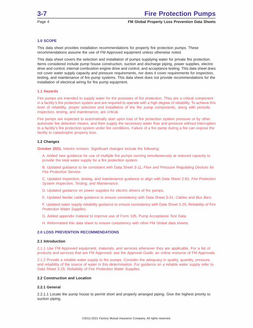
2.2.1.2 Locate the pump in a detached building of noncombustible construction a minimum of 50 ft (15 m)away from protected buildings.
When a detached building is not feasible:
A. Locate the pump room to prevent exposure from fire and falling debris or other exposures that woulddamage the pump or electrical feeder cables, or prevent the pump operator from remaining near the pumpduring a fire.
B. Provide an access door to the pump room along a building exterior wall.
C. Protect the fire pump from all other areas of the building by 2-hour fire-rated construction. If the pumproom and adjacent areas are protected with an automatic sprinkler system, the separation recommendationcan be reduced to 1-hour fire-rated construction.
D. Do not locate the fire pump room within or attached to an unprotected building.
2.2.1.3 Arrange any electrical control circuit wiring that extends outside the fire pump room so that failureof that wiring (open or short circuit) does not prevent operation of the pump. A fault in these wires can causethe fire pump to start and run but cannot prevent the fire pump from starting and running. Protect all controlwiring within the fire pump room that are not fault-tolerant against mechanical damage using metal conduitattached to the pump room roof or walls.
2.2.1.4 Do not use the pump room or pump house for storage purposes.
2.2.1.5 Provide automatic sprinklers over engine-driven pumps.
2.2.1.6 Provide suitable means for maintaining the temperature of a pump room or pump house, whererequired, above 40°F (5°C).
2.2.1.7 Provide ventilation for the pump room or pump house. See Section 2.8.5 for specific ventilationrequirements for diesel engines.
2.2.1.8 To lessen the likelihood of flooding, ensure the pump house floor is at or above the surrounding groundlevel. Locate the pump above the 500-year flood level and include 1-2 inches (25-50 mm) of freeboard.
Fig. 2.2.1.2-1 Photo of well arranged pump room
Fire Protection Pumps 3-7FM Global Property Loss Prevention Data Sheets Page 5
©2012-2021 Factory Mutual Insurance Company. All rights reserved.

2.2.1.9 Protect the fire pump, driver, and controller against possible interruption of service through damagecaused by explosion, fire, flood, earthquake, rodents, insects, windstorm, freezing, vandalism, and otheradverse conditions.
2.2.1.10 Pitch floors for adequate drainage of escaping water away from critical equipment such as the pump,driver, controller, etc. Provide a floor drain for the pump room or pump house to allow for easy removal ofwater from packed seals and pressure-drop testing.
2.2.1.11 Provide artificial lighting in the pump house/room so gauges and instrumentation can be read.
2.2.1.12 Provide the following alarms (at a minimum) connected to a constantly attended location:
A. For electric driven pumps:
• Pump (driver) running• Loss of power (AC and/or DC)• Controller connected to alternate power source (battery bank/generators where applicable)• Failure to start
B. For diesel driven pumps:
• Diesel driver running• Loss of power (AC and/or DC)• Controller off/in manual position/in TEST position (where applicable)• Failure to start
Sirens, horns or flashing lights that can be seen or heard in constantly attended areas are acceptable if aresponse to the pump issue can be ensured.
2.2.1.12.1 Provide the following additional visual or audible notifications for diesel driven fire pumps:
• Overspeed• Low oil pressure• Coolant high temperature• Engine failure
These alarms do not have to be constantly monitored at a central location.
These four (4) items can be classified together as a “General Pump Operation Failure” alarm or “Pump HouseTrouble” alarm for simplification.
2.2.1.12.2 Verify the operation of these alarms at least annually. This can be completed during the annualflow test of the applicable fire pump.
2.2.2 High-Rise Buildings
2.2.2.1 Locate all fire pumps on the first floor or a basement level of the building so direct access to thepump from the street level is possible. Consider flood exposure to the pump when it is located in a belowgrade level.
2.2.2.2 Do not install fire pumps in series.
2.2.2.3 Design systems so pressure-reducing valves are not needed. If the use of pressure reducing valvesis unavoidable, use FM Approved valves and install them per Data Sheet 3-11, Flow and Pressure RegulatingDevices for Fire Protection Service.
2.2.2.4 Supply sprinkler system water directly from a fire pump(s), a gravity tank of sufficient capacity andheight above the supplied sprinklers, or a combination of pumps and gravity tanks. See Figures 2.2.2.4-1 and2.2.2.4-2 for typical arrangements. Size the gravity tank filling pump so that it is capable of refilling the tankin 8 hours or less.
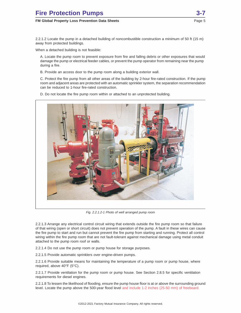
2.2.2.5 Limit the size of fire protection system zones in high-rise buildings to a maximum of 275 ft (85 m)vertically.
• Provide each zone with its own fire pump and independent fire service connections.
3-7 Fire Protection PumpsPage 6 FM Global Property Loss Prevention Data Sheets
©2012-2021 Factory Mutual Insurance Company. All rights reserved.
• For those zones above 275 ft (85 m), use high-pressure piping and fittings at the pump discharge andthe lower elevations of the building with a rated working pressure that is equal to or greater than themaximum no flow (churn) pressure of the fire pump plus the maximum anticipated static suction pressure.The rated working pressure of the pipe and fittings can be reduced at building floor levels where thepressure loss due to elevation reduces the maximum anticipated static pressure in the pipe.
• Where electric motor pump drivers are used and the height of the structure is beyond the pumpingcapability of the fire service apparatus, provide a reliable emergency source of power for the fire pumpinstallation.
Provide the emergency source of power from dedicated standby engine-driven generators or from buildingemergency power sources. In the latter case, size the emergency power source, so it is capable of supplyingthe total electrical demand, including that for the fire pump. For additional installation requirements referenceData Sheet 5-23, Emergency and Standby Power Systems.
Fig. 2.2.2.4-1. Single-zone pump system
Fire Protection Pumps 3-7FM Global Property Loss Prevention Data Sheets Page 7
©2012-2021 Factory Mutual Insurance Company. All rights reserved.

2.3 Protection
2.3.1 General
2.3.1.1 Support suction and discharge piping independently of the pump.
2.3.1.2 Keep the exterior of above ground steel piping painted to prevent corrosion.
2.3.1.3 Install and test all buried suction and discharge piping in accordance with Data Sheet 3-10, Installationand Maintenance of Private Fire Service Mains and Their Appurtenances.
2.3.1.4 For locations in earthquake-prone areas, refer to Data Sheet 2-8, Earthquake Protection forWater-Based Fire Protection Systems for additional suction and discharge pipe installation and bracingrecommendations.
2.3.2 Suction Piping
2.3.2.1 Verify that the pump suction pressure remains positive at all times over the entire range of pumpflow.
2.3.2.2 Ensure friction loss between any suction tank and pump suction inlet does not exceed 6 psi (0.4bar) at the pump’s 150% flow rate, which will ensure adequate net positive suction head (NPSH) requiredby the pump for conditions of a nearly empty tank. Include the equivalent lengths for elbows and fittings incalculations.
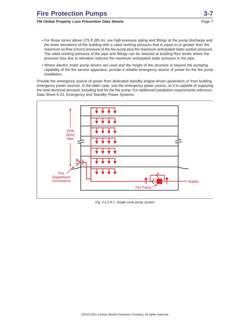
2.3.2.3 When the suction pipe is larger than the pump suction flange, connect them with an eccentric taperedreducer in such a way as to avoid air pockets. (See Figures 2.3.2.3-1 and 2.3.2.3-2.)
2.3.2.4 Do not install elbow and tee fittings with a centerline plane parallel to a horizontal split-case pumpunless the distance between the pump suction flange and the elbow or tee is greater than 10 times the suctionpipe diameter. (See Figure 2.3.2.3-2.)
Fig. 2.2.2.4-2. Two-zone pump system with redundant supply from gravity tanks
3-7 Fire Protection PumpsPage 8 FM Global Property Loss Prevention Data Sheets
©2012-2021 Factory Mutual Insurance Company. All rights reserved.
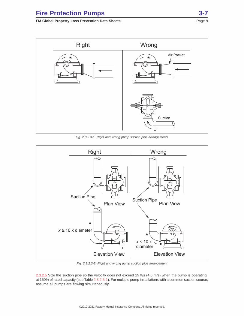
2.3.2.5 Size the suction pipe so the velocity does not exceed 15 ft/s (4.6 m/s) when the pump is operatingat 150% of rated capacity (see Table 2.3.2.5-1). For multiple pump installations with a common suction source,assume all pumps are flowing simultaneously.
Fig. 2.3.2.3-1. Right and wrong pump suction pipe arrangements
Fig. 2.3.2.3-2. Right and wrong pump suction pipe arrangement
Fire Protection Pumps 3-7FM Global Property Loss Prevention Data Sheets Page 9
©2012-2021 Factory Mutual Insurance Company. All rights reserved.

Table 2.3.2.5-1. Flow Required to Create 15 ft s (4.6 m s) Velocity
Pipe Size in. (mm) Flow, gpm (L/min) Pipe Size in. (mm) Flow, gpm (L/min)1 (25) 40 (151) 6(152) 1320(5000)
1 1⁄2 (38) 95 (360) 8(203) 2340(8860)2 (51) 155(587) 10(254) 3660(13850)
2 1⁄2 (64) 225(850) 12(305) 5280(19985)3 (76) 350(1325) 14(356) 6330(23960)
4 (102) 585 (2214) 16(406) 8280(31340)5 (127) 940 (3560)
2.3.2.6 Where the suction supply is of sufficient pressure to be of some fire protection value without the pump,install a bypass line around the pump equipped with a check valve. Size the bypass piping the same asthe pump discharge pipe. (See Figure 2.3.2.6-1.)
2.3.2.7 Do not install a device or assembly (including, but not limited to backflow prevention devices orassemblies) that will stop, restrict starting, or restrict the discharge of a fire pump or pump driver in the suctionpiping.
2.3.2.8 Locate backflow preventers on the discharge side of the fire pump whenever possible, due to theincreased friction loss and the potential negative effect on pump performance.
2.3.2.9 Do not install low suction pressure cut-off or regulating valves. As a substitute, provide monitoringdevices arranged to activate an alarm if the pump suction pressure or water level falls below a predeterminedminimum.
2.3.2.10 Replace suction regulating valves that are not FM Approved, if required by the authority havingjurisdiction, with FM Approved models.
2.3.2.11 Provide an FM Approved outside screw and yoke (OS&Y) gate valve in the suction pipe. To minimizewater turbulence into the pump, install only gate-type valves within 50 ft (16 m) of the pump suction flange.
2.3.2.12 Where the suction supply is from public water mains, locate the gate valve as far as practical fromthe suction flange on the pump. Where it comes from a stored water container, locate the gate valve at theoutlet of the container. The gate valve may be installed in the pump room on the inlet side of the eccentricsuction reducer, if provided. Size the OS&Y gate valve as indicated in Table 2.3.4.3-1 column headed “SuctionIn.”
Fig. 2.3.2.6-1. Schematic diagram of suggested arrangements for a fire pump with a by-pass, taking suction from publicmains
3-7 Fire Protection PumpsPage 10 FM Global Property Loss Prevention Data Sheets
©2012-2021 Factory Mutual Insurance Company. All rights reserved.
2.3.2.13 Perform hydrostatic leakage testing of suction piping in accordance with Data Sheet 3-10, Installation/Maintenance of Fire Service Mains. Use steel pipe with welded or threaded flanges, or mechanical groovefittings aboveground. Do not use adjustable type fittings or flexible pipe fittings unless specifically FMApproved for use with fire pumps.
2.3.2.14 Inspect suction screens/strainers per the guidance in Data Sheet 2-81, Fire Protection SystemInspection, Testing, and Maintenance.
2.3.2.14.1 Where the water supply is obtained from an open source such as a pond, lake or wet pit, or wherethere exists material in the water that might clog the pump or sprinkler system, apply the following guidance:
A. Provide double removable intake screens at the suction intake.
B. Ensure these screens have an effective net area of openings of 1 in.2 (650 mm2) for each gpm (3.8L/min) at 150% of rated pump capacity.
C. Ensure the flow of water into the suction (wet) pit is adequate to fill the tank.
D. Arrange the screens so they can be cleaned or repaired without disturbing the suction pipe.
E. Screens that are non-removable are to be inspected and cleaned at a minimum on an annual basis.
F. Slow flow rates and/or long filling times may indicate a blockage. Remove blockages when detected.Quarterly inspections, cleaning, and flow testing are recommended to verify suction supply availabilityunder these conditions.
2.3.2.17 Stored water supplied (tanks and reservoirs): For recommendations on stored water supply suctionpiping, see Data Sheet 3-2, Water Tanks for Fire Protection.
2.3.3 Discharge Piping
2.3.3.1 Install FM Approved discharge components consisting of valves such as check valves or backflowpreventers, pipes, and fittings.
2.3.3.2 Perform hydrostatic leakage testing of discharge piping in accordance with Data Sheet 2-0, InstallationGuidelines for Automatic Sprinklers. Use steel pipe with welded or threaded flanges, or mechanical groovedfittings aboveground. Do not use adjustable type fittings or flexible pipe fittings unless specifically FMApproved for use with fire pumps.
2.3.3.3 Ensure the pressure rating of the discharge piping is at least adequate for the maximum pressuredeveloped at the pump discharge, but never less than the component with the lowest-rated working pressurein the system.
2.3.3.4 Provide a means to test the fire pump installation at a minimum of 150% of the pump rated flowcapacity. Outlets can be provided through the use of standard test headers, yard hydrants, wall hydrants,flow meter loop, or standpipe hose valves. Size test outlets so they are capable of water flow of not less than175% of pump rated capacity.
2.3.3.5 If an in-line flow meter is installed, do not install a control valve within 10 pipe diameters of the flowmeter inlet or within 5 pipe diameters of the outlet.
2.3.3.6 Do not install a flow meter in a closed loop piped back to the pump suction piping. With a closedloop, if the suction supply valve were to be nearly shut, the near-closure would not be detected.
2.3.3.7 Large fire protection systems sometimes experience severe water hammer caused by back flow whenthe fire pump shuts down. Where conditions may be expected to cause damaging water hammer, installan FM Approved anti-water-hammer device in the discharge line of the fire pump.
2.3.4 Pressure Relief Valves
2.3.4.1 Avoid the use of pressure relief valves whenever possible by using proper system design techniquesto ensure the system will not experience excess pressure. Do not use the pressure relief valve to normallyrelieve excess pressure at lower pump flows.
2.3.4.1.1 Do not use pressure relief valves for a pump and tank configuration. Proper system designtechniques will ensure a pump and tank configuration do not experience the excessive pressures thatnecessitate the need for a pressure relief valve.
Fire Protection Pumps 3-7FM Global Property Loss Prevention Data Sheets Page 11
©2012-2021 Factory Mutual Insurance Company. All rights reserved.
2.3.4.2 Provide a main relief valve for pump installations (electric motor or diesel-driven) if the net rated shutoff(churn) pressure of the pump plus the maximum static suction pressure can exceed the rated pressure ofthe system components usually 175 psi (12 bar). The main relief valve is a safety device and should onlyoperate under abnormal overpressure conditions.
2.3.4.3 If a relief valve is required, install an FM Approved pressure relief valve as follows:
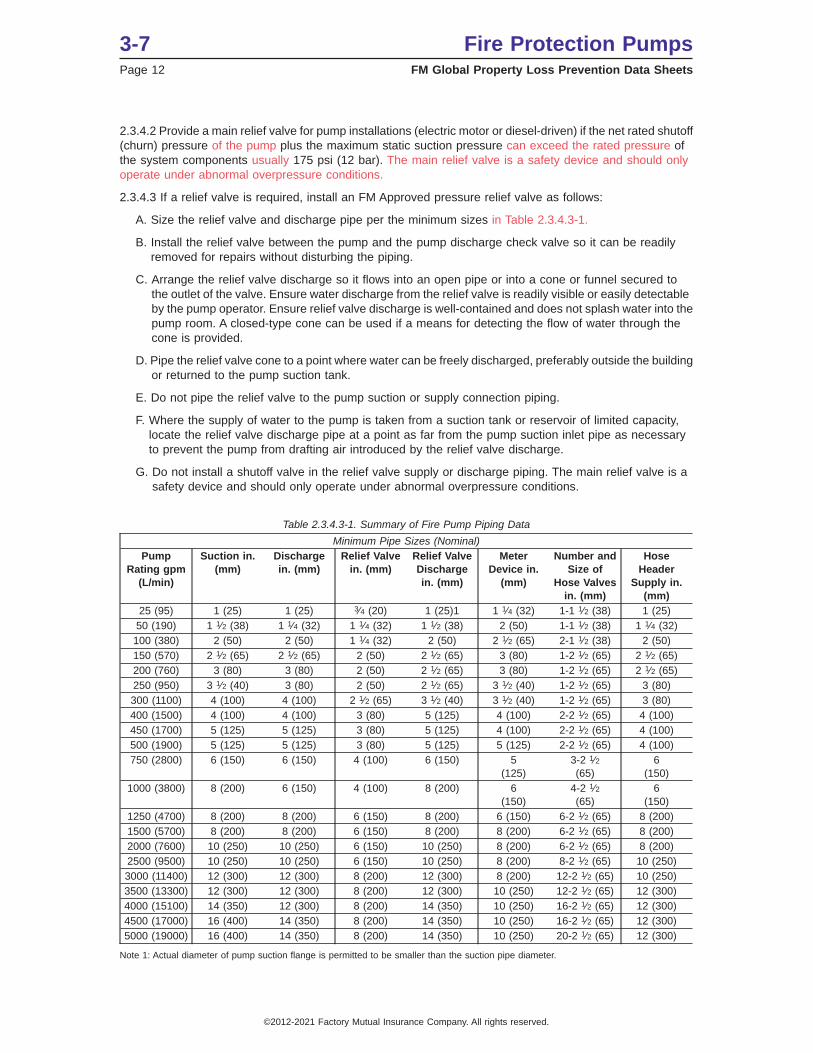
A. Size the relief valve and discharge pipe per the minimum sizes in Table 2.3.4.3-1.
B. Install the relief valve between the pump and the pump discharge check valve so it can be readilyremoved for repairs without disturbing the piping.
C. Arrange the relief valve discharge so it flows into an open pipe or into a cone or funnel secured tothe outlet of the valve. Ensure water discharge from the relief valve is readily visible or easily detectableby the pump operator. Ensure relief valve discharge is well-contained and does not splash water into thepump room. A closed-type cone can be used if a means for detecting the flow of water through thecone is provided.
D. Pipe the relief valve cone to a point where water can be freely discharged, preferably outside the buildingor returned to the pump suction tank.
E. Do not pipe the relief valve to the pump suction or supply connection piping.
F. Where the supply of water to the pump is taken from a suction tank or reservoir of limited capacity,locate the relief valve discharge pipe at a point as far from the pump suction inlet pipe as necessaryto prevent the pump from drafting air introduced by the relief valve discharge.
G. Do not install a shutoff valve in the relief valve supply or discharge piping. The main relief valve is asafety device and should only operate under abnormal overpressure conditions.
Table 2.3.4.3-1. Summary of Fire Pump Piping Data
Minimum Pipe Sizes (Nominal)Pump
Rating gpm(L/min)
Suction in.(mm)
Dischargein. (mm)
Relief Valvein. (mm)
Relief ValveDischargein. (mm)
MeterDevice in.
(mm)
Number andSize of
Hose Valvesin. (mm)
HoseHeader
Supply in.(mm)
25 (95) 1 (25) 1 (25) 3⁄4 (20) 1 (25)1 1 1⁄4 (32) 1-1 1⁄2 (38) 1 (25)50 (190) 1 1⁄2 (38) 1 1⁄4 (32) 1 1⁄4 (32) 1 1⁄2 (38) 2 (50) 1-1 1⁄2 (38) 1 1⁄4 (32)
100 (380) 2 (50) 2 (50) 1 1⁄4 (32) 2 (50) 2 1⁄2 (65) 2-1 1⁄2 (38) 2 (50)150 (570) 2 1⁄2 (65) 2 1⁄2 (65) 2 (50) 2 1⁄2 (65) 3 (80) 1-2 1⁄2 (65) 2 1⁄2 (65)200 (760) 3 (80) 3 (80) 2 (50) 2 1⁄2 (65) 3 (80) 1-2 1⁄2 (65) 2 1⁄2 (65)250 (950) 3 1⁄2 (40) 3 (80) 2 (50) 2 1⁄2 (65) 3 1⁄2 (40) 1-2 1⁄2 (65) 3 (80)300 (1100) 4 (100) 4 (100) 2 1⁄2 (65) 3 1⁄2 (40) 3 1⁄2 (40) 1-2 1⁄2 (65) 3 (80)400 (1500) 4 (100) 4 (100) 3 (80) 5 (125) 4 (100) 2-2 1⁄2 (65) 4 (100)450 (1700) 5 (125) 5 (125) 3 (80) 5 (125) 4 (100) 2-2 1⁄2 (65) 4 (100)500 (1900) 5 (125) 5 (125) 3 (80) 5 (125) 5 (125) 2-2 1⁄2 (65) 4 (100)750 (2800) 6 (150) 6 (150) 4 (100) 6 (150) 5
(125)3-2 1⁄2(65)
6(150)
1000 (3800) 8 (200) 6 (150) 4 (100) 8 (200) 6(150)
4-2 1⁄2(65)
6(150)
1250 (4700) 8 (200) 8 (200) 6 (150) 8 (200) 6 (150) 6-2 1⁄2 (65) 8 (200)1500 (5700) 8 (200) 8 (200) 6 (150) 8 (200) 8 (200) 6-2 1⁄2 (65) 8 (200)2000 (7600) 10 (250) 10 (250) 6 (150) 10 (250) 8 (200) 6-2 1⁄2 (65) 8 (200)2500 (9500) 10 (250) 10 (250) 6 (150) 10 (250) 8 (200) 8-2 1⁄2 (65) 10 (250)3000 (11400) 12 (300) 12 (300) 8 (200) 12 (300) 8 (200) 12-2 1⁄2 (65) 10 (250)3500 (13300) 12 (300) 12 (300) 8 (200) 12 (300) 10 (250) 12-2 1⁄2 (65) 12 (300)4000 (15100) 14 (350) 12 (300) 8 (200) 14 (350) 10 (250) 16-2 1⁄2 (65) 12 (300)4500 (17000) 16 (400) 14 (350) 8 (200) 14 (350) 10 (250) 16-2 1⁄2 (65) 12 (300)5000 (19000) 16 (400) 14 (350) 8 (200) 14 (350) 10 (250) 20-2 1⁄2 (65) 12 (300)
Note 1: Actual diameter of pump suction flange is permitted to be smaller than the suction pipe diameter.
3-7 Fire Protection PumpsPage 12 FM Global Property Loss Prevention Data Sheets
©2012-2021 Factory Mutual Insurance Company. All rights reserved.
2.3.5 Pressure Reducing Valves
2.3.5.1 Do not install pressure reducing valves on the suction or discharge of a fire pump.
2.3.5.2 Inspect, test, and maintain pressure reducing valves per the guidance in FM Global Data Sheet 3-11,Flow and Pressure Regulating Devices for Fire Protection Service.
2.4 Equipment and Processes
Provide one or more FM Approved pumps. Select the pumps based on the conditions under which they willoperate. Give consideration to the total amount of water and pressures required at the pump discharge forautomaticsprinklers and hose streams. Ensure pumps provide not less than 150% of rated flow at not less than65% of the rated pump pressure.
2.4.1 Split Case, End Suction, and In-Line Centerfugal Pumps
2.4.1.1 Do not use these pumps where a static suction lift is required.
2.4.1.2 Ensure the pump has an air-release valve having 1⁄2 in. (12.7 mm) minimum diameter dischargedto atmosphere. End suction pumps with a top discharge, or vertically mounted split case pumps, will naturallyvent the air and do not require an air-release valve.
2.4.1.3 Install a pipeline strainer for any pump installations that require removal of the driver to clear rocksor debris from the pump impeller. Install the strainer a minimum of 10 pipe diameters from the suction flange.
2.4.2 Vertical Shaft Turbine-Type Pumps
2.4.2.1 Use a vertical shaft turbine-type pump where the water supply level is located below the dischargeflange or the water supply pressure is insufficient for supplying water to the fire pump suction.
2.4.2.2 Ensure the pump bowl assembly is submerged below the suction source surface to a sufficient depthto meet the manufacturers’ minimum submergence requirement. The requirement must be met at theminimum water depth that includes tidal suction sources or empty tank conditions.
2.4.2.3 Do not include the water volume below the pump’s minimum submergence requirement whendetermining the water supply duration.
2.4.2.4 Right-angle gear drives: Use an FM Approved gear drive sized so both the maximum power requiredby the pump and the maximum thrust forces generated by the pump are less than or equal to the gear drivenameplate rating.
2.4.2.5 For diesel-driven vertical turbine pumps, verify a mass elastic torsional analysis of the system (engine,coupling, gear drive, and pump) has been conducted to ensure there are no damaging stresses or criticalspeeds in the range of 25% above and below the operating speed of the system components.
2.4.3 Positive Displacement Pumps
2.4.3.1 Positive displacement pumps are used for pumping water (water mist), foam concentrates, oradditives. Consider the liquid viscosity as part of the pump selection.
2.4.3.2 Provide a pressure relief valve on the pump discharge capable of relieving 100% of the pump capacity.Set the pressure relief valve to relieve at or below a pressure equal to the lowest rated working pressureof any component in the system, and above the demand pressure.
2.4.3.3 Provide positive displacement pumps with an unloader valve that remains open during the pumpstarting sequence until the pump driver is at operating speed.
2.4.3.4 Provide positive displacement pumps with a removable and cleanable suction strainer installed atleast 10 pipe diameters from the pump suction inlet. Consider suction strainer pressure drop in hydrauliccalculations to ensure sufficient NPSH is available to the pump. Ensure the net open area of the strainer isat least four times the area of the suction piping. Ensure strainer mesh size is in accordance with the pumpmanufacturer’s recommendation.
2.4.4 Mounting, Coupling, and Alignment
2.4.4.1 Mount the pump and driver securely to a solid foundation on a common base plate.
Fire Protection Pumps 3-7FM Global Property Loss Prevention Data Sheets Page 13
©2012-2021 Factory Mutual Insurance Company. All rights reserved.

2.4.4.2 Provide a foundation sufficiently substantial to form permanent and rigid support for the pump anddriver base plate.
2.4.4.3 Connect the pump and driver with a rigid coupling, flexible coupling, or flexible connecting shaft. Donot use all elastomeric (plastic) couplings. An all-elastomeric coupling is one that relies solely on anelastomeric material for power transmission. Examples of recommended couplings are:
• Pin and bushing
• Jaw
• Disc
• Drive shaft
• Steel-grid-type couplings, if the drive components are metallic
Direct connection or “close-coupling” of the pump and driver is acceptable for electrically driven, in-line,vertically mounted, horizontal split case, and end-suction pumps.
2.4.4.4 Align pumps and drivers on separately coupled-type pumps in accordance with the coupling and pumpmanufacturers’ specifications. Ensure ongoing fire pump alignment is in accordance with Data Sheet 2-81,Fire Protection System Inspection, Testing, and Maintenance.
2.4.4.5 For locations in earthquake-prone areas, refer to Data Sheet 2-8, Earthquake Protection forWater-based Fire Protection Systems, for additional equipment securement and bracing requirements.
2.4.5 Mechanical Seals
2.4.5.1 Only use pumps that have been specifically FM Approved for use with mechanical shaft seals.
2.4.5.2 Only use pumps equipped with mechanical seals in systems that meet the following criteria:
A. The suction source water is clean. Do not use pumps with mechanical seals in systems where anywater source is an open body of water (e.g., retention pond, lake, or river).
B. The suction pressure is positive under all conditions of pump flow.
C. A spare split mechanical seal set is maintained on site.
D. Weekly testing of the pump is conducted.
2.4.6 Pump Sizing
2.4.6.1 Size the pump to meet the maximum required flow and pressure demand for the system (Qmax).
2.4.6.2 The standard water supply for pump and tank configurations are to be made of either one 100% Qmaxpump or three (3) 50% of Qmax pumps. For non-storage occupancies, it is acceptable to use two (2) pumpsof different driver types, electrical and diesel, equally sized, each meeting a minimum 75% of Qmax (formultiple pump installations, the characteristic pump curves should be identical).
2.4.6.3 If flow and pressure demand cannot be provided by the standard water supply, use N-Number ofpumps, equally sized (for multiple pump installations, the characteristic pump curves should be identical),to meet the maximum required flow and pressure demand (Qmax). However, N+1 Pumps need to be installed,preferably half electrically driven and half diesel driven.
2.4.6.4 For centrifugal pumps, use a maximum of 140% of the pump rated flow capacity to meet the combinedsystem demand and hose streams (if also supplied by the fire pump), if one 100% Qmax pump is used.
2.4.6.5 For multiple centrifugal pumps, use a maximum of 110% of the pump rated flow capacity to meet thecombined system demand and hose streams (if also supplied by the fire pump).
2.4.6.6 Size the pump driver equal to or larger than the maximum peak power required by the pump at anypoint over its entire flow range. See Sections 2.4.19 and 2.5.1 for more information.
2.4.6.7 Size a booster pump’s rated pressure based on the minimum anticipated suction pressure at themaximum required flow demand of the system. Review the daily and seasonal fluctuations in supply pressureto determine the minimum anticipated pump suction pressure.
3-7 Fire Protection PumpsPage 14 FM Global Property Loss Prevention Data Sheets
©2012-2021 Factory Mutual Insurance Company. All rights reserved.

2.4.7 Pump Starting and Control
2.4.7.1 Provide an FM Approved fire pump controller to start and control the pump driver.
2.4.7.2 Arrange fire pumps to start automatically at a predetermined water pressure or by water flow.
2.4.7.3 Arrange fire pumps supplying water to sprinklers and hoses for automatic starting and manualstopping. Manual stopping requires that whenever the pump starts, the pump house is visited by appropriatepersonnel to determine that the pump package is running properly, and to ensure the pump is not stoppeduntil it is ascertained that pump starting causes have returned to normal and any fire emergency has beensuccessfully resolved.
2.4.7.4 Maintain underground mains and provide a pressure maintenance (jockey) pump. Do not use thefire pump as a pressure maintenance pump.
2.4.8 Sequence Starting
2.4.8.1 If more than one pump arranged in parallel is required to operate to meet the water demand, setthe pumps to prevent simultaneous starting. Arrange the pump starting so failure of a pump to start does notprevent subsequent pumps from starting.
2.4.9 Automatic Weekly Test Timers
2.4.9.1 If an automatic weekly test feature is provided by the fire pump controller, do not rely on it to testthe pump without supervision. Arrange for appropriate personnel to respond and be in attendance for allpump-running situations, including scheduled tests, to monitor proper operation of the pump unit during thetest, identify and correct problems, and to ensure the unit is left in proper operating condition after the test.
2.4.10 Run-Period Timers
2.4.10.1 Arrange the pump controller for manual stopping. This requires the controller run-period timer (ifprovided) to be defeated. Do not set the run-period timer to “zero” as a means of converting from automaticstop to manual stop. Use the correct method for defeating the controller run-period timer, which can be foundin the operation and maintenance manual of all FM Approved controllers.
2.4.11 Pressure Switches
2.4.11.1 For all pump installations (including jockey pumps), each controller will have its own individualpressure-sensing line.
2.4.11.1.1 For pressure switches with a high and low actuation settings, adjust the switch so the lowadjustment setting initiates pump starting.
2.4.11.2 Connect the controller pressure-sensing line for each pump (including jockey pumps) between thepump’s discharge check valve and the discharge control valve. Ensure the line is made of a corrosion-resistant material (brass, copper, or series-300 stainless steel pipe or tube and fittings) and has a minimuminternal diameter of 1⁄2 in. (12.7 mm) nominal size.
2.4.11.3 Do not install a shutoff valve in the pressure-sensing line. Valves that release water in thepressure-sensing line to facilitate pump testing are acceptable.
2.4.11.4 For pressure-surge dampening, install two check valves in the pressure-sensing line at least 5 ft(1.5 m) apart with a single 3⁄32 in. (2.4 mm) hole drilled in the check valve clapper to serve as dampening.Install the check valve flow arrow toward the sense line connection at the pump discharge.
2.4.11.5 Set the start pressure of the fire pump as close as possible to the expected no flow (churn) pressuredeveloped by the fire pump to avoid water hammer.
2.4.11.6 Arrange the fire pump system, when started by pressure drop, as follows:
A. The jockey pump start point equals the pump pressure at churn (zero flow) plus the maximum staticpump suction pressure plus 5 psi.
B. The jockey pump stop point is 10 psi (70 kPa) more than the jockey pump start point.
C. The fire pump start point is 5-10 psi (35-70 kPa) less than the jockey pump start point. Use 10 psi(70 kPa) decrements for each additional pump start.
Fire Protection Pumps 3-7FM Global Property Loss Prevention Data Sheets Page 15
©2012-2021 Factory Mutual Insurance Company. All rights reserved.
Example:
• Pump: 1000 gpm, 80 psi pump with churn pressure of 95 psi.
• Suction Supply:- 50 psi from city-minimum static.- 60 psi from city-maximum static.
• Jockey pump start = 95 + 60 + 5 = 160 psi
• Jockey pump stop = 160 + 10 = 170 psi
• Fire pump start = 160 – (5-10) = 150-155 psi
• For SI units: 1 psi = 0.0689 bar.
2.4.12 Power Supply Arrangement: Electric Motor Driven Pumps
2.4.12.1 Carefully review the reliability of the electric power source. Consider the possibility of fire damagingpower lines located either on the property or on adjacent properties.
2.4.12.2 Supplement unreliable power sources with a second, independent source of power, such as anemergency generator or alternate utility connection, or provide a diesel engine-driven pump.
A reliable power source has infrequent power disruptions from environmental or man-made conditions. Anelectric power source that has disruptions lasting longer than 8 hours three or more times in a 12-month periodis considered unreliable. More frequent short-term outages would also be considered unreliable.
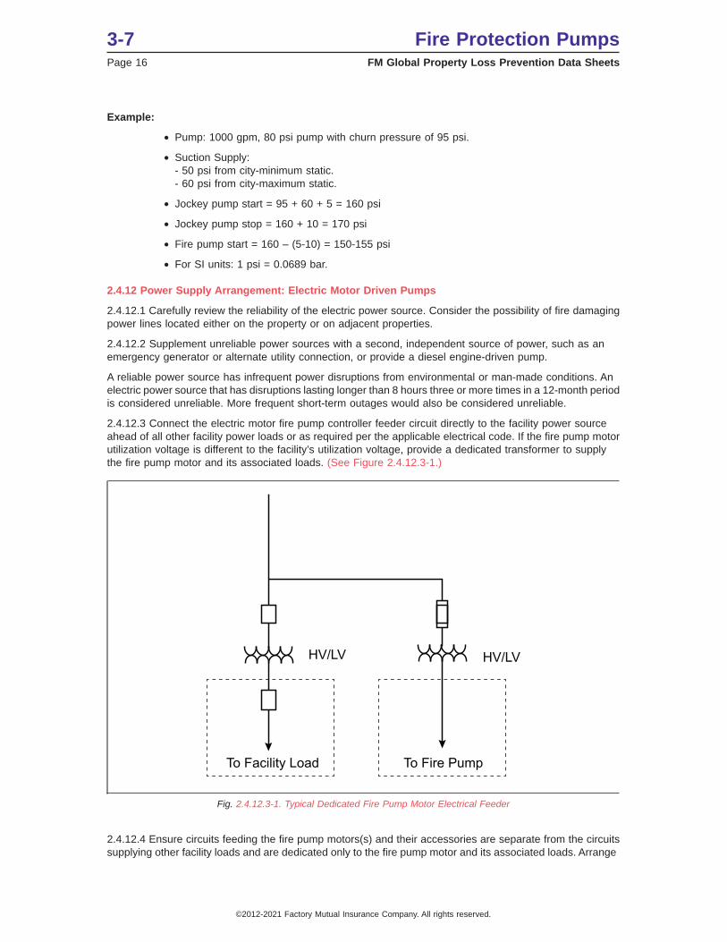
2.4.12.3 Connect the electric motor fire pump controller feeder circuit directly to the facility power sourceahead of all other facility power loads or as required per the applicable electrical code. If the fire pump motorutilization voltage is different to the facility’s utilization voltage, provide a dedicated transformer to supplythe fire pump motor and its associated loads. (See Figure 2.4.12.3-1.)
2.4.12.4 Ensure circuits feeding the fire pump motors(s) and their accessories are separate from the circuitssupplying other facility loads and are dedicated only to the fire pump motor and its associated loads. Arrange
To Facility Load To Fire Pump
HV/LV HV/LV
Fig. 2.4.12.3-1. Typical Dedicated Fire Pump Motor Electrical Feeder
3-7 Fire Protection PumpsPage 16 FM Global Property Loss Prevention Data Sheets
©2012-2021 Factory Mutual Insurance Company. All rights reserved.
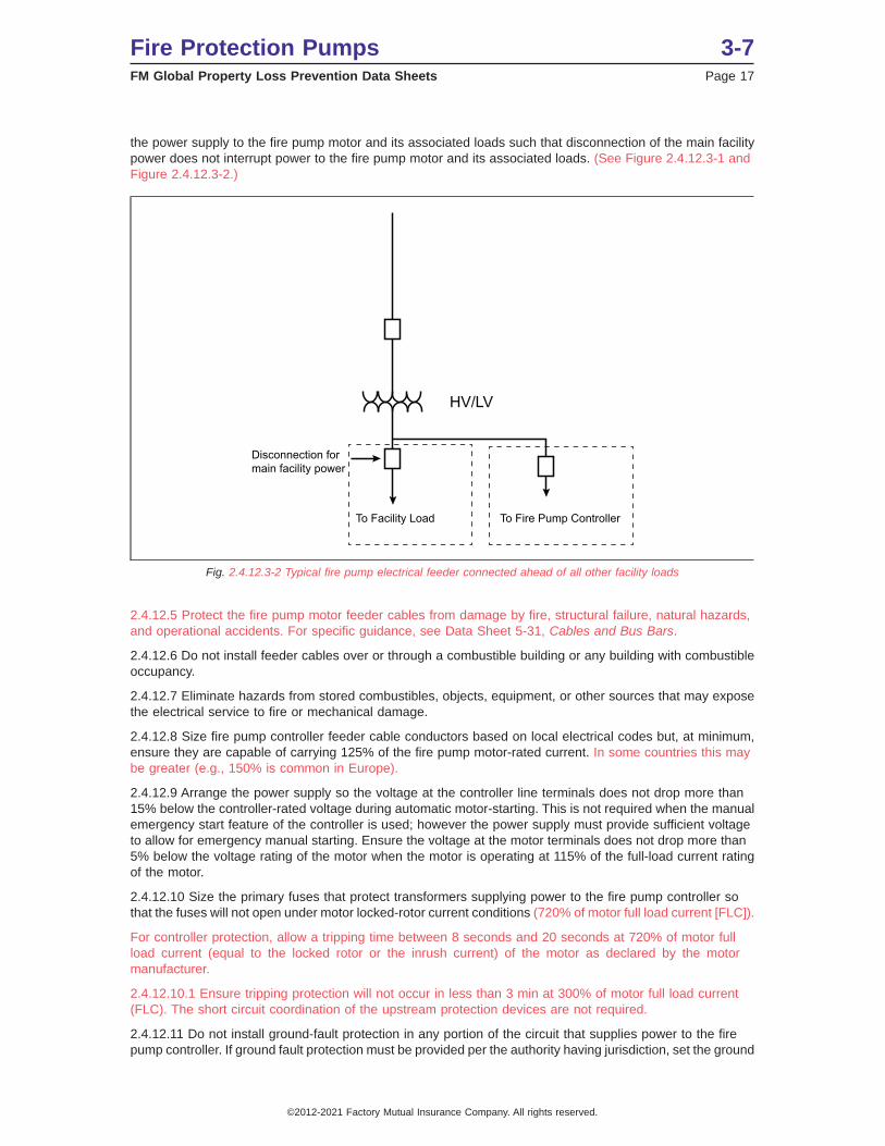
the power supply to the fire pump motor and its associated loads such that disconnection of the main facilitypower does not interrupt power to the fire pump motor and its associated loads. (See Figure 2.4.12.3-1 andFigure 2.4.12.3-2.)
2.4.12.5 Protect the fire pump motor feeder cables from damage by fire, structural failure, natural hazards,and operational accidents. For specific guidance, see Data Sheet 5-31, Cables and Bus Bars.
2.4.12.6 Do not install feeder cables over or through a combustible building or any building with combustibleoccupancy.
2.4.12.7 Eliminate hazards from stored combustibles, objects, equipment, or other sources that may exposethe electrical service to fire or mechanical damage.
2.4.12.8 Size fire pump controller feeder cable conductors based on local electrical codes but, at minimum,ensure they are capable of carrying 125% of the fire pump motor-rated current. In some countries this maybe greater (e.g., 150% is common in Europe).
2.4.12.9 Arrange the power supply so the voltage at the controller line terminals does not drop more than15% below the controller-rated voltage during automatic motor-starting. This is not required when the manualemergency start feature of the controller is used; however the power supply must provide sufficient voltageto allow for emergency manual starting. Ensure the voltage at the motor terminals does not drop more than5% below the voltage rating of the motor when the motor is operating at 115% of the full-load current ratingof the motor.
2.4.12.10 Size the primary fuses that protect transformers supplying power to the fire pump controller sothat the fuses will not open under motor locked-rotor current conditions (720% of motor full load current [FLC]).
For controller protection, allow a tripping time between 8 seconds and 20 seconds at 720% of motor fullload current (equal to the locked rotor or the inrush current) of the motor as declared by the motormanufacturer.
2.4.12.10.1 Ensure tripping protection will not occur in less than 3 min at 300% of motor full load current(FLC). The short circuit coordination of the upstream protection devices are not required.
2.4.12.11 Do not install ground-fault protection in any portion of the circuit that supplies power to the firepump controller. If ground fault protection must be provided per the authority having jurisdiction, set the ground
To Facility Load To Fire Pump Controller
Disconnection formain facility power
HV/LV
Fig. 2.4.12.3-2 Typical fire pump electrical feeder connected ahead of all other facility loads
Fire Protection Pumps 3-7FM Global Property Loss Prevention Data Sheets Page 17
©2012-2021 Factory Mutual Insurance Company. All rights reserved.
fault protection to trip at currents above the motor locked rotor current. Also set the ground fault protectionso it will not operate on motor start-up. Conduct a reliability study of any fire pump circuit provided with groundfault protection.
2.4.13 Electric Motors
2.4.13.1 Ensure electric motors for fire pump service are designed in accordance with either the NationalElectrical Manufacturers Association (NEMA) Standard MG-1 or the International ElectrotechnicalCommission (IEC) Standard IEC34-1.
2.4.13.2 Electric motors for fire pump service require a winding insulation temperature rating of NEMA/IECClass B 130°C (266°F) or greater.
2.4.13.3 To protect against water ingress, electric motors for fire pump service require minimum ratingequivalent to a NEMA open drip poof type or have a minimum IEC rating of IP22.
2.4.13.4 Size the motor in horsepower or kilowatts such that the maximum motor current in any phase underany anticipated condition of pump load and voltage unbalance does not exceed the motor rated full-loadcurrent multiplied by the motor service factor.
2.4.13.5 Ensure that the rated motor power provided is on a continuous (not intermittent) duty basis.
2.4.14 Electric Motor Controllers
2.4.14.1 Provide an FM Approved fire pump controller.
2.4.14.2 Locate the controller within sight of and as close as practical to its motor.
2.4.14.3 Provide remote electronic monitoring of the fire pump controller unless constant attendance andprompt personnel response can be ensured at all times.
2.4.14.4 Do not use the fire pump controller as an electrical junction box to supply power to other pump roomequipment. This includes pressure maintenance (jockey or make-up) pump(s).
2.4.14.5 Size the pump controller to be greater than or equal to the motor size in horsepower or kilowatts.
2.4.14.6 Limited service controllers: Do not use limited service controllers for fire pumps supplying primarybuilding sprinkler protection. The use of this controller type is limited to 30 hp (22 kW) and less and maybe suitable for use to control additive (foam) pumps, other special protection system pumps, or standpipehose connection pumps.
2.4.15 Power Transfer Switches
2.4.15.1 Use only FM Approved combination fire pump controller and transfer switches or stand-alone firepump power transfer switches.
2.4.15.2 Size the power transfer switch to have a power rating at least equal to the motor power or, whererated in amperes, not less than 115% of the motor full-load current. Ensure the power transfer switch issuitable for switching the motor locked rotor current.
2.4.15.3 If an alternate power source is required for reliability, ensure the positions of the transfer switchand the alternate power source switch are remotely supervised. Provide a suitable over-current protectiondevice for the transfer switch if the short circuit current available from the alternate source exceeds the firepump motor locked rotor current. Size the over-current protection device for the alternate power source tocarry the fire pump motor lock rotor current plus any other pump room loads indefinitely.
2.4.16 Variable Speed Electric Pumps
2.4.16.1 Provide a main relief valve for pump installations if the net rated shutoff (churn) pressure, plus themaximum pump static suction pressure of the pump itself (uncontrolled) can exceed 232 psi (16 bar). Withoutthis the inbuilt safety margins of sprinkler components can potentially be exceeded.
Refer also to the guidance in Section 2.3.4 for pressure-relief valves.
2.4.16.2 Use only FM Approved variable speed electric fire pump controllers.
2.4.16.3 Limit the cable length between the controller and the motor to 100 ft (30 m) maximum.
3-7 Fire Protection PumpsPage 18 FM Global Property Loss Prevention Data Sheets
©2012-2021 Factory Mutual Insurance Company. All rights reserved.
2.4.16.4 In addition to the motor requirements of Section 2.7.2, use only motors that are specifically “inverterduty” rated. In addition, do not use the motor service factor when sizing the motor. Use only the rated poweron the motor nameplate.
2.4.16.5 Ensure operation at minimum speed does not result in overheating of the motor.
2.4.16.6 Ensure the variable speed pressure sensor is dedicated to the variable speed control andindependent of the pressure starting switch. Do not use a common pressure control for multi-pumpinstallations.
2.4.16.7 Ensure the regulated target pressure is greater than the maximum system demand pressure at themaximum required flow.
2.4.16.8 During pump churn (no flow) testing, ensure the motor speed is regulating the pump dischargepressure to within 5% of target pressure (175 psi [12 bar] is typical).
2.4.16.9 Ensure the controller output power frequency never exceeds the controller input line frequency (50Hz or 60 Hz).
2.4.16.10 Record the pressure limit setting and pump start pressure in or on the fire pump controller cabinet.Set the controller for manual stopping only.
2.4.17 Diesel Engine-Driven Pumps
2.4.17.1 Use only FM Approved diesel engines intended for fire pump service. FM Approved engines areone of the following types:
A. Closed circuit, liquid-cooled with pump discharge water heat exchanger (heat-exchanger-cooled); or
B. Closed circuit, liquid-cooled with a radiator and engine driven fan (radiator-cooled).
2.4.18 Engine Sizing
2.4.18.1 Deduct 3% from the rated engine power for diesel engines for every 1,000 feet (305 m) altitudeabove 300 ft (90 m).
2.4.18.2 Do not de-rate engine power for high temperature unless combustion air temperatures can exceed105°F (40°C). Deduct 3% from rated engine horsepower at temperatures equal to or greater than 105°F(40°C). Limit the maximum ambient temperature to 120°F (49°C). Consider pump room temperature rise fromengine heat when determining the maximum combustion air temperature.
2.4.18.3 Where right-angle gear drives are used between the vertical-turbine pump and its driver, increasethe horsepower of the pump to allow for power loss in the gear drive. See Section 2.4.2 for more informationon vertical turbine pumps and right angle gear drives.
2.4.18.4 After the above de-rating, ensure the engine de-rated power is equal to or greater than the powerrequired to drive the pump at its rated speed under any conditions of pump load.
2.4.19 Diesel Engine Controller
2.4.19.1 Use FM Approved fire pump controllers.
2.4.19.2 Locate controllers as close as practical and within sight of the engine.
2.4.19.3 Provide remote electronic monitoring of the fire pump controller unless constant attendance andprompt personnel response can be ensured at all times.
2.4.19.4 Do not use the fire pump controller as an electrical junction box to supply power to other pump roomequipment. This includes pressure maintenance (jockey or make-up) pump(s).
2.4.20 Power Failure Starting
2.4.20.1 Ensure pump room temperature is maintained above 40°F (4°C) and the diesel engine cooling waterremains above 70°F (20°C) during power failures. To accomplish this, the diesel engine may be arrangedto automatically start; however, provide this arrangement only if an immediate response from trainedpersonnel can be guaranteed. Before arranging a fire pump for automatic starting upon power failure, giveconsideration to abnormal facility shut-down, such as during severe natural hazard events, when a power
Fire Protection Pumps 3-7FM Global Property Loss Prevention Data Sheets Page 19
©2012-2021 Factory Mutual Insurance Company. All rights reserved.

failure is likely and a trained response would be unlikely. If the pump is not supervised and starts on powerfailure, depletion of the fuel supply and/or pump overheating can occur.
2.4.21 Fuel Tank and Piping
2.4.21.1 Store the diesel engine fuel in a double-walled steel tank or a concrete vault style tank.
2.4.21.2 Provide each fuel tank with individual fill, drain, and vent connections.
2.4.21.3 Locate diesel fuel storage tanks inside the pump room. Extend the tank fill and vent lines outdoors.If they cannot be located in the pump room, provide a reliable means of maintaining the fuel storage tanktemperature above 40°F (4°C).
2.4.21.4 Provide spill containment curbing around indoor fuel tanks. Design the curbing around the fuel tankto contain the entire contents of the tank plus 2 in. (5 cm) freeboard.
2.4.21.5 Do not use glass or plastic liquid level sight tubes on the fuel storage tank.
2.4.21.6 Size the fuel supply tank(s) for a minimum of 8 hours of engine run time, plus 5% volume forexpansion and 5% volume for sump. Reserve the fuel supply tank and fuel exclusively for use by the firepump diesel engine.
2.4.21.7 Where prompt replenishment of fuel supply is unlikely, provide an on-site reserve supply tank alongwith facilities for fuel transfer to the supply tank.
2.4.21.8 For multi-pump installations, provide separate fuel lines and separate fuel supply tanks for eachengine.
2.4.21.9 Do not connect the fuel supply line to the bottom of the tank. Locate the fuel supply line tankconnection so 5% of the tank volume is reserved as a sump volume not usable by the engine. In addition,arrange the fuel supply line tank connection so that its relative height is higher than the engine fuel pump.Verify the engine manufacturer’s fuel pump maximum static pressure is not exceeded when the level of thefuel in the tank is at maximum.
2.4.21.10 Provide the fuel line recommended in Section 2.4.21.9 with a 1⁄4-turn ball valve at the point ofconnection to the tank. Lock this valve open.
2.4.21.11 Provide a mechanical guard or use protected piping for all exposed fuel lines.
2.4.21.12 Provide flame-resistant flexible fuel hoses rated for this service at the engine for connection tothe fuel system piping.
2.4.21.13 Install the fuel return line per the engine manufacturer’s recommendation. Do not install shutoffvalves in the fuel return line to the tank.
2.4.21.14 Use only the type and grade of diesel fuel specified by the engine manufacturer. Ensure theminimum pour point and cloud point of the fuel is 30°F (-1°C) or less. Do not use biodiesel fuels due to fuelstability problems when stored for long periods of time.
2.4.21.15 Where an electric solenoid valve is used to control the engine fuel supply, arrange it to be capableof manual mechanical operation or of being manually bypassed in the event of control circuit failure.
2.4.21.16 For specific recommendations addressing the fire exposure of the diesel fuel tank installation, seeData Sheet 7-32, Ignitable Liquid Operatopns.
2.4.22 Ventilation
2.4.22.1 Provide room ventilation that ensures the following:
A. The maximum temperature under any conditions is maintained at 120°F (49°C) or less when measuredat the combustion air cleaner inlet.
B. Sufficient air for engine combustion
C. Removal of any hazardous vapors
D. Sufficient room air changes for radiator-cooled engines
3-7 Fire Protection PumpsPage 20 FM Global Property Loss Prevention Data Sheets
©2012-2021 Factory Mutual Insurance Company. All rights reserved.
2.4.22.2 For heat exchanger-cooled diesel engines, provide ventilation openings in the pump room of at least0.75 in.2/Hp (6.5 cm2/KW).
2.4.22.3 Duct cooling air from the radiator to outside the pump room through free-swinging louvers havingan effective net area of at least one and one-half times the area of the radiator air outlet.
2.4.22.4 Interlock the pump room ventilation system (louvers and fans) with engine operation. Do not usea thermostat to control room ventilation. For optimum room ventilation, locate the air supply ventilator and airdischarge vent on opposite walls.
2.4.23 Manual Starting
2.4.23.1 Provide two manual-starting contactors (one for each battery) and the required fuel and coolingcontrols at the engine, independent of the fire pump controller.
2.4.23.2 Ensure the sequence for emergency manual operation (arranged in step-by-step manner) is postedon the fire pump engine, and the pump operator is familiar with the procedure.
2.4.24 Batteries
2.4.24.1 Provide each engine with two separate starting batteries. Size each battery to have twice the capacitysufficient to maintain the cranking speed recommended by the engine manufacturer (120 rpm is typical)through a 3-minute “attempt to start” cycle (15 seconds cranking and 15 seconds of rest, in six consecutivecycles) at a temperature of 40°F (4.5°C). In addition, ensure the batteries are capable of starting the enginefor a minimum of 90 hours following a power failure.
2.4.24.2 Ensure lead-acid, nickel-cadmium, and other kinds of batteries are compatible with the batterychargers in the controller. Install and maintain them in accordance with the battery manufacturer’s instructions.
2.4.24.3 Do not place starting batteries directly on the pump room floor. Locate the batteries above the floor,preferably on a supporting rack, secured against movement, and located where they will not be subject toexcessive temperature, vibration, mechanical injury, or flooding by water. Locate the batteries so they arereadily accessible for servicing. Determine the minimum battery cable size and maximum length based onthe engine manufacturer’s instructions in the engine manual.
2.4.24.4 Do not install current-carrying conductors (battery and signal cables) to and from the engine lessthan 12 in. (300 mm) above floor level.
2.4.25 Engine Cooling
2.4.25.1 Open-Loop Heat Exchanger-Cooled Engines
2.4.25.1.1 Connect the cooling water supply piping for heat exchanger-type engine cooling systems directlyto the discharge of the pump, at a point before the pump discharge check valve. Use rigid piping for thisconnection.
2.4.25.1.2 Provide the cooling water supply piping with the following:
A. a label showing the intended direction of flow
B. an indicating manual shutoff valve
C. an FM Approved flushing-type strainer
D. a pressure regulator
E. an automatic valve
F. a second indicating manual shutoff valve; and
G. a pressure gauge towards the engine after the last manual valve
An automatic valve (E) is not required on vertical shaft turbine-type pump or any other pump when there isno pressure in the discharge when the pump is idle.
2.4.25.1.3 Provide a bypass line with manual valves, flush-type strainer, and a pressure regulator aroundthe manual shutoff valve, strainer, pressure regulator, and automatic valve. (See Figure 2.4.25.1.3-1.)
Fire Protection Pumps 3-7FM Global Property Loss Prevention Data Sheets Page 21
©2012-2021 Factory Mutual Insurance Company. All rights reserved.

2.4.25.1.4 Size the pressure regulator so it is capable of flowing approximately 120% of the cooling waterrequired when the engine is operating at maximum power. Additionally ensure the regulator can supply therequired cooling water flow at 65% and 140% of the pump’s rated discharge pressure. Base the cooling waterflow on the engine manufacturer’s instructions, taking into account the potential maximum cooling-watertemperature.
2.4.25.2 Closed-Loop Radiator-Cooled Engines
2.4.25.2.1 Ensure adequate air flow through the room and radiator. For a radiator-cooled engine, anengine-driven fan will push the air through the radiator that must be exhausted from the room via the airdischarge ventilator.
2.4.25.2.2 Obtain combustion and cooling air from outside the pump room through free-swinging louvershaving an effective net area of at least two times the area of the radiator air outlet.
2.4.25.2.3 Duct cooling air from the radiator to outside the pump room through free-swinging louvers havingan effective net area of at least one and one-half times the area of the radiator air outlet.
2.4.26 Diesel Engine Speed
2.4.26.1 Ensure the diesel engine speed is set within 10% of the speed marked on the pump nameplate.Ensure the pump flow and pressure output exceeds the maximum facility fire protection water demand. Adjustthe speed governor to correct if necessary. Do not exceed the diesel engine nameplate rated speed by morethan 10%.
2.4.27 Variable-Speed Diesel Pumps
2.4.27.1 Provide a system pressure relief valve as recommended in Section 2.6.
2.4.27.2 Ensure the sense line for pressure control purposes is a minimum of 1⁄2 in. (12.7 mm) nominal insidediameter. Connect the sense line on the pump discharge piping between the pump and the discharge checkvalve.
2.4.27.3 Ensure the target pressure limit is greater than the maximum system demand pressure at themaximum required flow.
2.4.27.4 During pump churn (no flow) testing, ensure the engine speed is regulating the pump dischargepressure to within 5% of target pressure (175 psi [12 bar] is typical).
Fig. 2.4.25.1.3-1. Diagram of a typical heat exchanger cooling water piping arrangement.
3-7 Fire Protection PumpsPage 22 FM Global Property Loss Prevention Data Sheets
©2012-2021 Factory Mutual Insurance Company. All rights reserved.
2.5 Operations and Maintenance
2.5.1.1 Conduct a field acceptance test on all fire pumps upon installation. Obtain a copy of the manufacturer’scertified pump test characteristic curve for comparison to the results of the field acceptance test. The firepump as installed should equal or better the pump performance as indicated on the manufacturer’s certifiedshop test curve within the accuracy of the test equipment. If this is not the case, investigate the cause ofthe discrepancy and correct it. See Appendix C for acceptance test procedures.
2.5.1.2 Ensure the fire pump performs at minimum, rated, and peak loads without overheating or damageof any component.
2.5.1.3 Ensure vibrations of the fire pump assembly are not of a magnitude to cause damage to any firepump component.
3.0 SUPPORT FOR RECOMMENDATIONS
3.1 Supplemental Information
3.1.1 Construction and Location
Holes and penetrations through pump room fire walls can be packed with mineral wool or other suitablematerial held in place by pipe collars on each side of the wall.
It is desirable to provide clearance of 1 in (25 mm) or more for pipes passing through foundation walls orpit walls into the ground, but ensure the penetrations are sealed watertight. Space around pipes passingthrough pump room walls or pump house floors may be filled with asphalt mastic.
For earthquake protection see Data Sheet 2-8, Earthquake Protection for Water-Based Fire ProtectionSystems.
In pump rooms, vertical shaft turbine-type pumps may require a removable panel in the pump house roofto permit the pump to be removed for inspection or repair. Provide proper clearances to equipment asrecommended by the manufacturer’s drawings.
For maximum reliability and equipment life, pump rooms and pump houses must be kept dry and free ofcondensate. A room heater may be required to accomplish this.
3.1.2 High-Rise Buildings
Fire pumps may be used for automatic sprinkler systems, standpipe and hose systems, and combinedsystems (automatic sprinkler systems having standpipe type hose outlets for fire service use).
Vertical series staging of fire pumps creates unacceptable reliability concerns.
In vertical series staging, the first (lowest) pump discharges to the first-zone sprinklers and the suction ofthe second pump; the second pump discharges to the second-zone sprinklers and the suction of the thirdpump; etc. If fire occurred near the top of a building having three vertical zones, it would be necessary for thefirst pump to start, then the second, then the third. Any one of the three pumps failing to start would preventwater from being supplied to the upper floor sprinklers.
With an approximately 3% failure-to-start rate for electric-motor-driven units, the reliability for the third zoneis reduced from 97% to 91%. Almost one in eleven times, there is no water available in the third zone.
3.1.3 Pump Suction and Discharge Piping
Where the fire pump suction supply is from a factory-use water system, it is desirable to verify that pumpoperation at 150% of rated capacity does not create hazardous process upsets due to low water pressure.
Turbulent flow created by components located upstream from the pump suction inlet should be minimizedto prevent degradation of the pump performance. The distance of 10 pipe diameters is a general guidelinethat has been used by the water control industry. This distance is considered to be adequate only if all flowand pressure criteria for pump acceptance are met.
Fire Protection Pumps 3-7FM Global Property Loss Prevention Data Sheets Page 23
©2012-2021 Factory Mutual Insurance Company. All rights reserved.
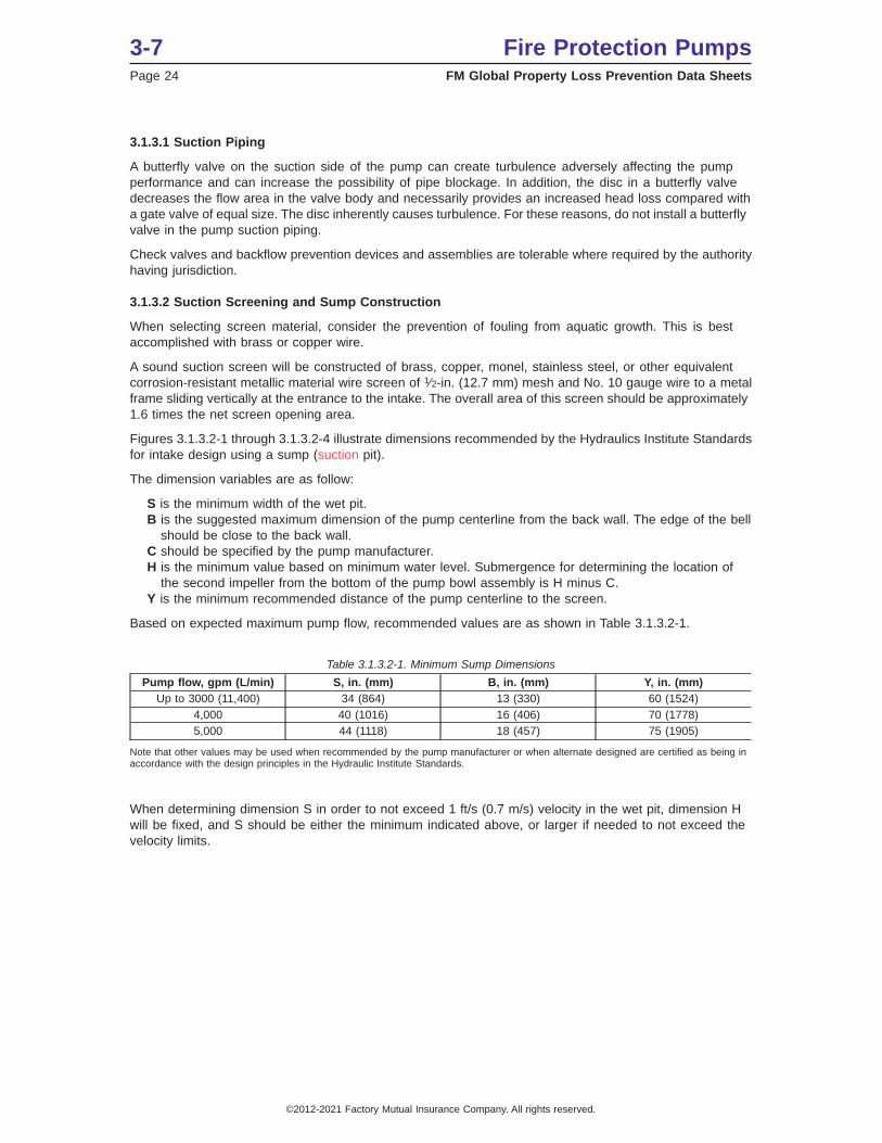
3.1.3.1 Suction Piping
A butterfly valve on the suction side of the pump can create turbulence adversely affecting the pumpperformance and can increase the possibility of pipe blockage. In addition, the disc in a butterfly valvedecreases the flow area in the valve body and necessarily provides an increased head loss compared witha gate valve of equal size. The disc inherently causes turbulence. For these reasons, do not install a butterflyvalve in the pump suction piping.
Check valves and backflow prevention devices and assemblies are tolerable where required by the authorityhaving jurisdiction.
3.1.3.2 Suction Screening and Sump Construction
When selecting screen material, consider the prevention of fouling from aquatic growth. This is bestaccomplished with brass or copper wire.
A sound suction screen will be constructed of brass, copper, monel, stainless steel, or other equivalentcorrosion-resistant metallic material wire screen of 1⁄2-in. (12.7 mm) mesh and No. 10 gauge wire to a metalframe sliding vertically at the entrance to the intake. The overall area of this screen should be approximately1.6 times the net screen opening area.
Figures 3.1.3.2-1 through 3.1.3.2-4 illustrate dimensions recommended by the Hydraulics Institute Standardsfor intake design using a sump (suction pit).
The dimension variables are as follow:
S is the minimum width of the wet pit.B is the suggested maximum dimension of the pump centerline from the back wall. The edge of the bell
should be close to the back wall.C should be specified by the pump manufacturer.H is the minimum value based on minimum water level. Submergence for determining the location of
the second impeller from the bottom of the pump bowl assembly is H minus C.Y is the minimum recommended distance of the pump centerline to the screen.
Based on expected maximum pump flow, recommended values are as shown in Table 3.1.3.2-1.
Table 3.1.3.2-1. Minimum Sump Dimensions
Pump flow, gpm (L/min) S, in. (mm) B, in. (mm) Y, in. (mm)Up to 3000 (11,400) 34 (864) 13 (330) 60 (1524)
4,000 40 (1016) 16 (406) 70 (1778)5,000 44 (1118) 18 (457) 75 (1905)
Note that other values may be used when recommended by the pump manufacturer or when alternate designed are certified as being inaccordance with the design principles in the Hydraulic Institute Standards.
When determining dimension S in order to not exceed 1 ft/s (0.7 m/s) velocity in the wet pit, dimension Hwill be fixed, and S should be either the minimum indicated above, or larger if needed to not exceed thevelocity limits.
3-7 Fire Protection PumpsPage 24 FM Global Property Loss Prevention Data Sheets
©2012-2021 Factory Mutual Insurance Company. All rights reserved.

Fig. 3.1.3.2-2. Vertical shaft turbine-type pump installation in a wet pit
Fire Protection Pumps 3-7FM Global Property Loss Prevention Data Sheets Page 25
©2012-2021 Factory Mutual Insurance Company. All rights reserved.
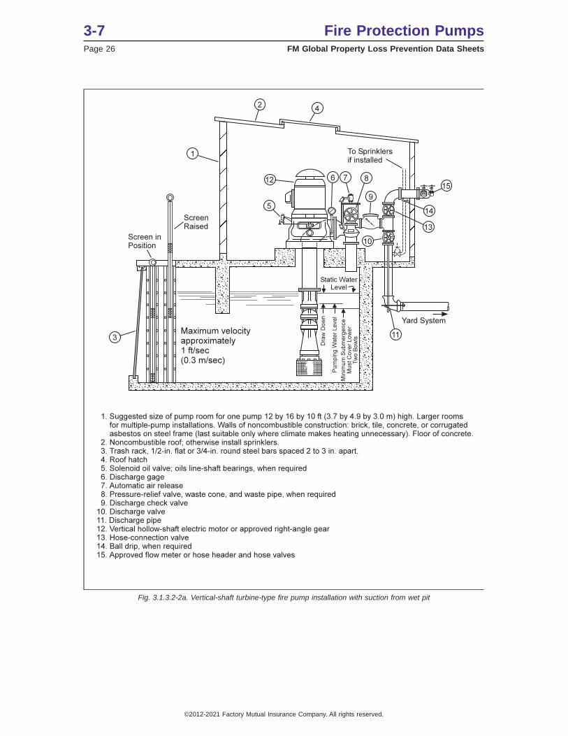
Fig. 3.1.3.2-2a. Vertical-shaft turbine-type fire pump installation with suction from wet pit
3-7 Fire Protection PumpsPage 26 FM Global Property Loss Prevention Data Sheets
©2012-2021 Factory Mutual Insurance Company. All rights reserved.
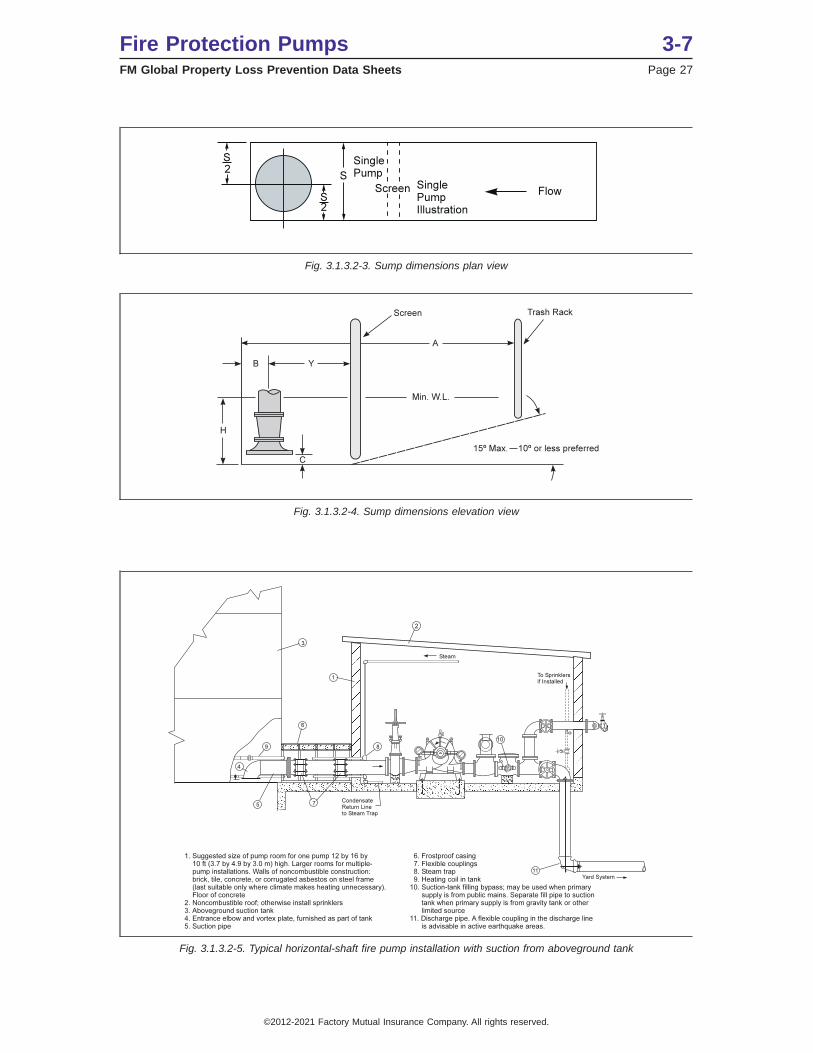
Fig. 3.1.3.2-3. Sump dimensions plan view
Fig. 3.1.3.2-4. Sump dimensions elevation view
Fig. 3.1.3.2-5. Typical horizontal-shaft fire pump installation with suction from aboveground tank
Fire Protection Pumps 3-7FM Global Property Loss Prevention Data Sheets Page 27
©2012-2021 Factory Mutual Insurance Company. All rights reserved.
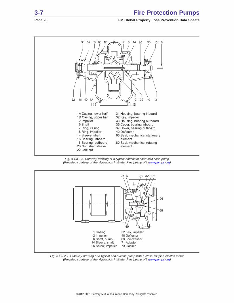
Fig. 3.1.3.2-6. Cutaway drawing of a typical horizontal shaft split case pump(Provided courtesy of the Hydraulics Institute, Parsippany, NJ www.pumps.org)
Fig. 3.1.3.2-7. Cutaway drawing of a typical end suction pump with a close coupled electric motor(Provided courtesy of the Hydraulics Institute, Parsippany, NJ www.pumps.org)
3-7 Fire Protection PumpsPage 28 FM Global Property Loss Prevention Data Sheets
©2012-2021 Factory Mutual Insurance Company. All rights reserved.

Fig. 3.1.3.2-8. Cutaway drawing of a typical separately coupled end suction pump(Provided courtesy of the Hydraulics Institute, Parsippany, NJ www.pumps.org)
Fire Protection Pumps 3-7FM Global Property Loss Prevention Data Sheets Page 29
©2012-2021 Factory Mutual Insurance Company. All rights reserved.

Fig. 3.1.3.2-9. Cutaway drawing of a typical vertical in-line pump with a close coupled electric motor(Provided courtesy of the Hydraulics Institute, Parsippany, NJ www.pumps.org)
3-7 Fire Protection PumpsPage 30 FM Global Property Loss Prevention Data Sheets
©2012-2021 Factory Mutual Insurance Company. All rights reserved.
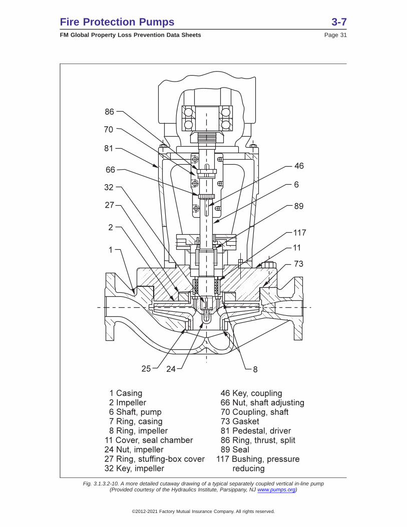
Fig. 3.1.3.2-10. A more detailed cutaway drawing of a typical separately coupled vertical in-line pump(Provided courtesy of the Hydraulics Institute, Parsippany, NJ www.pumps.org)
Fire Protection Pumps 3-7FM Global Property Loss Prevention Data Sheets Page 31
©2012-2021 Factory Mutual Insurance Company. All rights reserved.
3.1.4 Split Case, End Suction, and In-Line Centrifugal Pumps
3.1.4.1 Limited-Service Pumps
Limited-service fire pumps furnish not less than 130% of rated capacity at not less than 65% of rated head.They are limited to a maximum of 30 hp across-the-line starting electric motor drive only.
3.1.5 Vertical Shaft Turbine-Type Pumps
The vertical shaft turbine-type pump is particularly suitable for fire pump service when the source of wateris located below ground and where it would be difficult to install any other type of pump below the minimumwater level. It was originally designed for installation in drilled wells, but is equally suitable to be used tolift water from lakes, streams, open reservoirs, and other subsurface sources like underground tanks. Bothoil-lubricated enclosed-lineshaft and water-lubricated open-lineshaft pumps are used. (See Figure 3.1.5-1.)
3-7 Fire Protection PumpsPage 32 FM Global Property Loss Prevention Data Sheets
©2012-2021 Factory Mutual Insurance Company. All rights reserved.
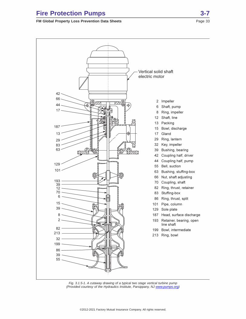
Fig. 3.1.5-1. A cutaway drawing of a typical two stage vertical turbine pump(Provided courtesy of the Hydraulics Institute, Parsippany, NJ www.pumps.org)
Fire Protection Pumps 3-7FM Global Property Loss Prevention Data Sheets Page 33
©2012-2021 Factory Mutual Insurance Company. All rights reserved.
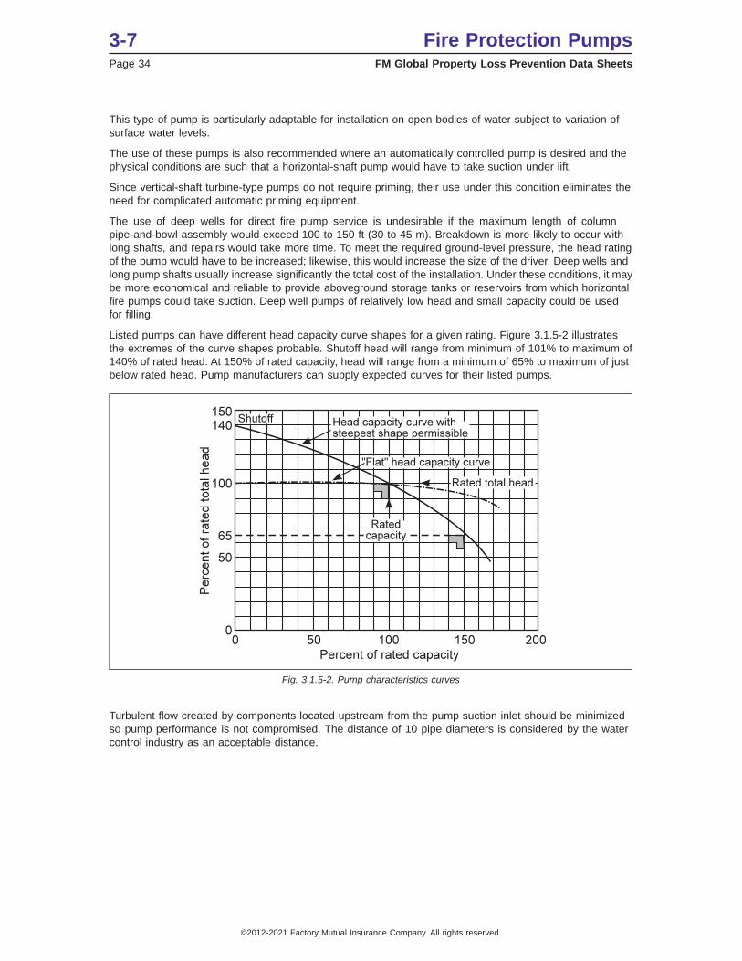
This type of pump is particularly adaptable for installation on open bodies of water subject to variation ofsurface water levels.
The use of these pumps is also recommended where an automatically controlled pump is desired and thephysical conditions are such that a horizontal-shaft pump would have to take suction under lift.
Since vertical-shaft turbine-type pumps do not require priming, their use under this condition eliminates theneed for complicated automatic priming equipment.
The use of deep wells for direct fire pump service is undesirable if the maximum length of columnpipe-and-bowl assembly would exceed 100 to 150 ft (30 to 45 m). Breakdown is more likely to occur withlong shafts, and repairs would take more time. To meet the required ground-level pressure, the head ratingof the pump would have to be increased; likewise, this would increase the size of the driver. Deep wells andlong pump shafts usually increase significantly the total cost of the installation. Under these conditions, it maybe more economical and reliable to provide aboveground storage tanks or reservoirs from which horizontalfire pumps could take suction. Deep well pumps of relatively low head and small capacity could be usedfor filling.
Listed pumps can have different head capacity curve shapes for a given rating. Figure 3.1.5-2 illustratesthe extremes of the curve shapes probable. Shutoff head will range from minimum of 101% to maximum of140% of rated head. At 150% of rated capacity, head will range from a minimum of 65% to maximum of justbelow rated head. Pump manufacturers can supply expected curves for their listed pumps.
Turbulent flow created by components located upstream from the pump suction inlet should be minimizedso pump performance is not compromised. The distance of 10 pipe diameters is considered by the watercontrol industry as an acceptable distance.
Fig. 3.1.5-2. Pump characteristics curves
3-7 Fire Protection PumpsPage 34 FM Global Property Loss Prevention Data Sheets
©2012-2021 Factory Mutual Insurance Company. All rights reserved.
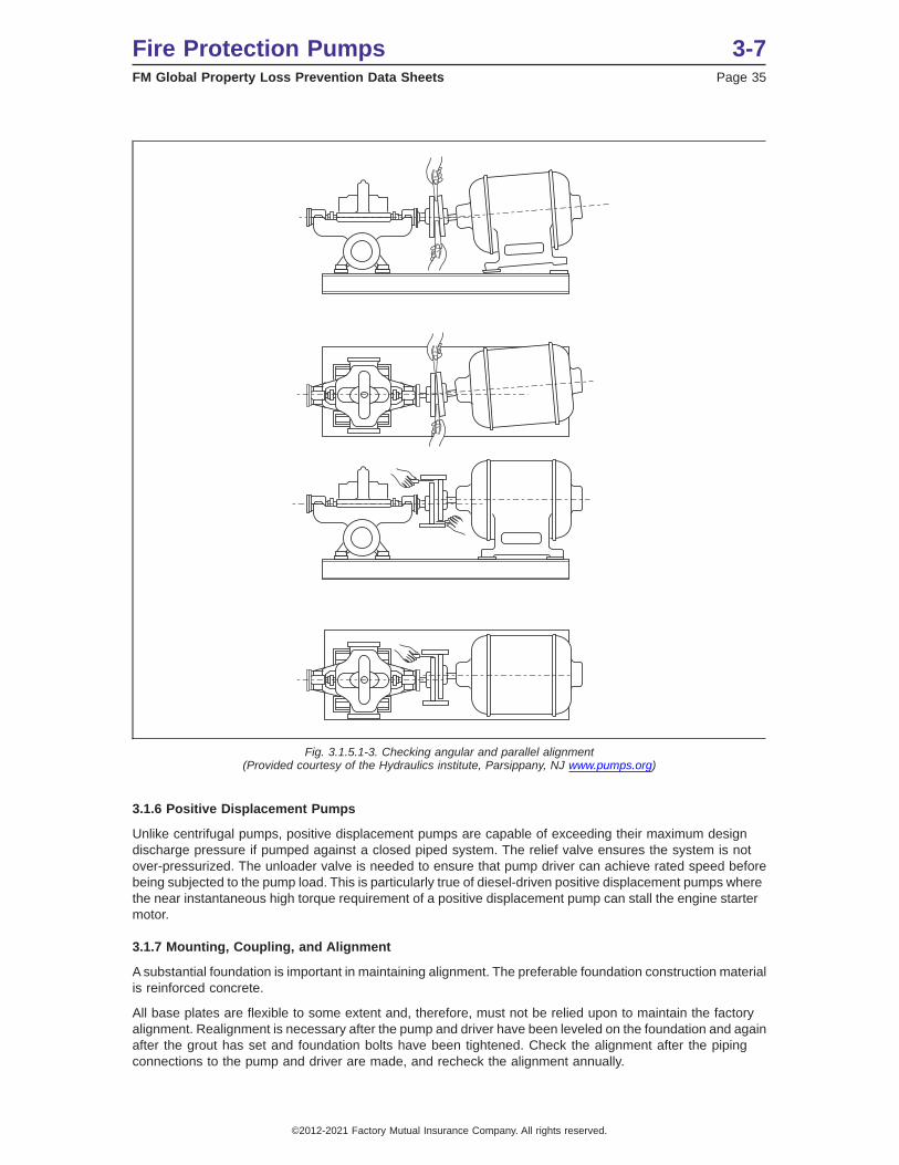
3.1.6 Positive Displacement Pumps
Unlike centrifugal pumps, positive displacement pumps are capable of exceeding their maximum designdischarge pressure if pumped against a closed piped system. The relief valve ensures the system is notover-pressurized. The unloader valve is needed to ensure that pump driver can achieve rated speed beforebeing subjected to the pump load. This is particularly true of diesel-driven positive displacement pumps wherethe near instantaneous high torque requirement of a positive displacement pump can stall the engine startermotor.
3.1.7 Mounting, Coupling, and Alignment
A substantial foundation is important in maintaining alignment. The preferable foundation construction materialis reinforced concrete.
All base plates are flexible to some extent and, therefore, must not be relied upon to maintain the factoryalignment. Realignment is necessary after the pump and driver have been leveled on the foundation and againafter the grout has set and foundation bolts have been tightened. Check the alignment after the pipingconnections to the pump and driver are made, and recheck the alignment annually.
Fig. 3.1.5.1-3. Checking angular and parallel alignment(Provided courtesy of the Hydraulics institute, Parsippany, NJ www.pumps.org)
Fire Protection Pumps 3-7FM Global Property Loss Prevention Data Sheets Page 35
©2012-2021 Factory Mutual Insurance Company. All rights reserved.
After the pump and driver have been placed on the foundation, disconnect the coupling halves. Keep thecoupling disconnected until all the shaft alignment operations have been completed. The purpose of theflexible coupling is to compensate for temperature changes and to permit end movement of the shafts withoutinterference with each other while transmitting power from the driver to the pump.
There are two forms of misalignment between the pump shaft and the driver shaft, as follows:
A. Angular misalignment: shafts with axes concentric but not parallel.
B. Parallel misalignment: shafts with axes parallel but not concentric.
Space the faces of the coupling halves within the manufacturer’s recommended limits. Make an allowancefor wear of the thrust bearings that will cause the pump shaft to move in the axial direction. The necessary toolsfor an approximate check of the alignment of flexible coupling are a straight edge and taper gage or set offeeler gages.
A check for angular alignment is made by inserting the taper gage or feelers at four points between thecoupling faces and comparing the distance between the faces at four points spaced at 90-degree intervalsaround the coupling. The pump and driver shafts will be in angular alignment when the measurements showthe coupling faces are the same distance apart at all points.
A check for parallel alignment is made by placing a straight edge across both coupling rims at the top, bottom,and at both sides. The pump and driver shafts will be in parallel alignment when the straight edge rests evenlyon the coupling rim at all positions. Allowance may be necessary for temperature changes and for couplinghalves that are not of the same outside diameter. Care must be taken to have the straight edge parallel to theaxes of the shafts.
When the alignment is correct, the foundation bolts should be tightened evenly, but not too firmly. The baseplate can then be grouted to the foundation. The base plate can be completely filled with grout, and it isdesirable to grout the leveling pieces, shims or wedges in place. Foundation bolts cannot be fully tighteneduntil the grout is hardened, usually about 48 hours after pouring. After the grout has set and the foundationbolts have been properly tightened, check the pump and driver for parallel and angular alignment and, ifnecessary, take corrective measures. After the piping has been connected to the pump and driver, checkthe alignment once more.
At this time, the direction of driver rotation can be verified to make certain it matches that of the pump. Thecorresponding direction of rotation of the pump is indicated by a direction arrow on the pump casing.
The coupling halves can then be reconnected. With the pump properly primed, the pump can be operatedunder normal operating conditions until temperatures have stabilized. Following engine shut down,immediately check for alignment of the coupling. All alignment checks must be made with the coupling halvesdisconnected and again after they are reconnected.
After the pump has been in operation for about 10 hours, the coupling halves should be given final checkfor misalignment caused by pipe or temperature strains. If the alignment is correct, both pump and drivershould be doweled to the base plate. Dowel installation and location is very important, especially if theequipment is subjected to temperature changes. Obtain the recommended locations from the manufacturer.
If the pump does not stay aligned after being properly installed, the following are possible causes:
A. Settling, seasoning or springing of the foundation
B. Pipe stress distorting or shifting the pump
C. Wear of the bearings
D. Springing of the base plate due to temperature
E. Shifting of the building structure due to variable loading or other causes
It may be necessary to slightly readjust the alignment from time to time while the pump and foundation arenew.
3-7 Fire Protection PumpsPage 36 FM Global Property Loss Prevention Data Sheets
©2012-2021 Factory Mutual Insurance Company. All rights reserved.

3.1.8 Mechanical Seals
Mechanical shaft seals are an alternative to traditional soft packing around the shaft as it exits the pumpbody. Mechanical seals have the advantage of not normally leaking water around the pump shaft. Soft packinghas the advantage of being readily available and easily replaceable.
Mechanical pump seal designs can be vulnerable to total seal failure due to damage from water supplycontaminates or adhesion of the seal faces due to long periods of inactivity. The total loss of the seal willincapacitate the pumping ability of the pump. Replacement mechanical seals can be difficult to source andrequire dismantling the pump. Therefore, check water quality and verify regular testing can be accomplishedbefore a mechanical seal is selected for use in a particular application. (See Fig. 3.1.8-1.)
3.1.9 Pump Sizing
The capacity and pressure of a fire pump can be determined for each individual fire protection system onlyafter due consideration of all the factors involved. For determining approximate pump flow and pressurerequirements, refer to the appropriate FM Global occupancy data sheet listed in Section 4.1.
Where pumps are to supply automatic sprinklers and/or hose streams/hydrants, refer to FM Global DataSheets 2-0, Installation Guidelines for Automatic Sprinklers, 4-4N, Standpipe and Hose Systems, and anyrelevant occupancy data sheet that addresses water demands.
Table 3.1.9-1. Approximate Power Required to Drive Fire Pump.(Consult Manufacturer for Specific Power Requirements)
Capacity gpm (L/min) Pressure psi (bar)Approximate Brake Horsepower
(kW)500 (1900) 75 (5) 30-40 (22-30)
100 (7) 50-60 (37-45)125 (9) 60-70 (45-52)
750 (2800) 75 (5) 50-60(37-45)100 (7) 60-75 (45-56)125 (9) 75-125 (56-93)
1000 (3800) 75 (5) 90-100 (67-75)100 (7) 75-100 (56-75)125 (9) 125 (93)
1500 (5700) 75 (5) 90-100 (67-75)100 (7) 125 (93)125 (9) 150-200 (112-150)
2000 (7600) 75 (5) 100-125 (75-93)100 (7) 150-200(112-150)125 (9) 200-250 (150-190)
2500 (9500) 75 (5) 125-150 (93-112)100 (7) 200 (150)125 (9) 250-300 (190-225)
Fig. 3.1.8-1.. Mechanical Pump Seal
Fire Protection Pumps 3-7FM Global Property Loss Prevention Data Sheets Page 37
©2012-2021 Factory Mutual Insurance Company. All rights reserved.
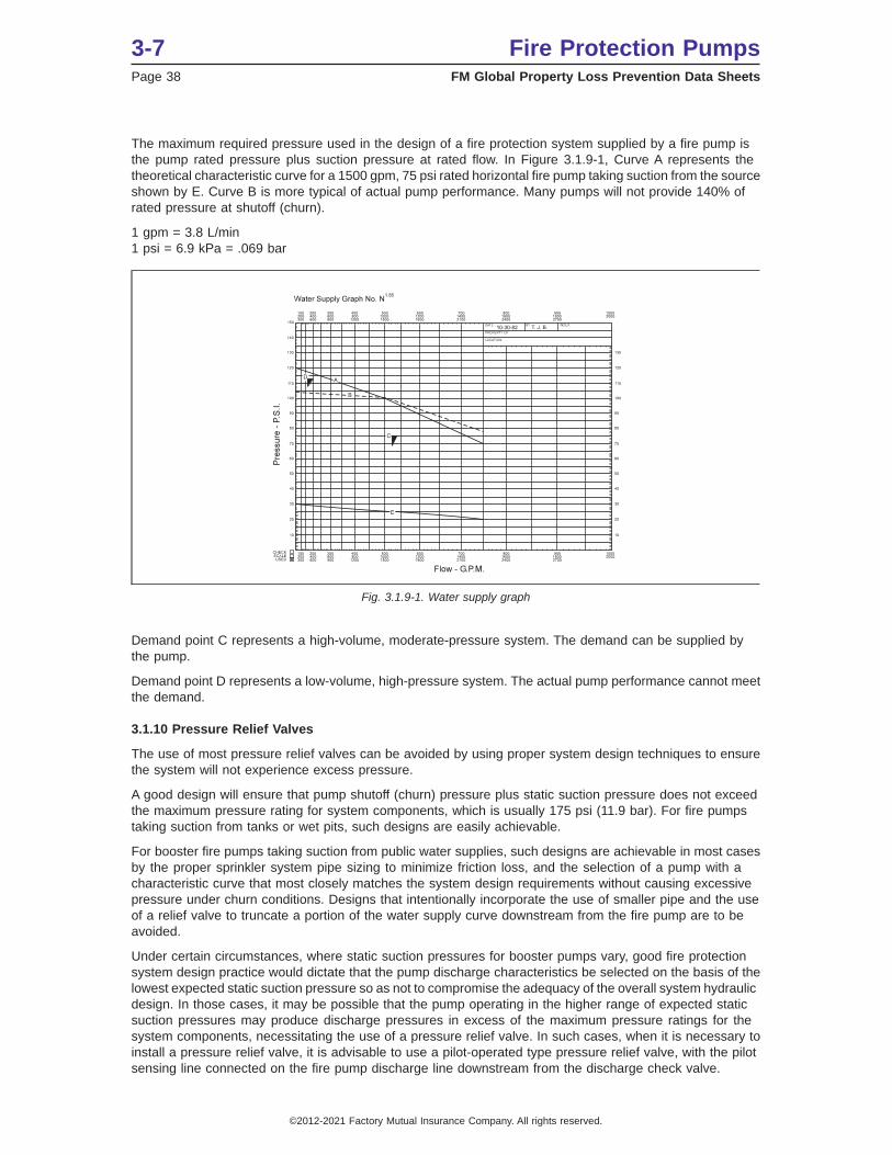
The maximum required pressure used in the design of a fire protection system supplied by a fire pump isthe pump rated pressure plus suction pressure at rated flow. In Figure 3.1.9-1, Curve A represents thetheoretical characteristic curve for a 1500 gpm, 75 psi rated horizontal fire pump taking suction from the sourceshown by E. Curve B is more typical of actual pump performance. Many pumps will not provide 140% ofrated pressure at shutoff (churn).
1 gpm = 3.8 L/min1 psi = 6.9 kPa = .069 bar
Demand point C represents a high-volume, moderate-pressure system. The demand can be supplied bythe pump.
Demand point D represents a low-volume, high-pressure system. The actual pump performance cannot meetthe demand.
3.1.10 Pressure Relief Valves
The use of most pressure relief valves can be avoided by using proper system design techniques to ensurethe system will not experience excess pressure.
A good design will ensure that pump shutoff (churn) pressure plus static suction pressure does not exceedthe maximum pressure rating for system components, which is usually 175 psi (11.9 bar). For fire pumpstaking suction from tanks or wet pits, such designs are easily achievable.
For booster fire pumps taking suction from public water supplies, such designs are achievable in most casesby the proper sprinkler system pipe sizing to minimize friction loss, and the selection of a pump with acharacteristic curve that most closely matches the system design requirements without causing excessivepressure under churn conditions. Designs that intentionally incorporate the use of smaller pipe and the useof a relief valve to truncate a portion of the water supply curve downstream from the fire pump are to beavoided.
Under certain circumstances, where static suction pressures for booster pumps vary, good fire protectionsystem design practice would dictate that the pump discharge characteristics be selected on the basis of thelowest expected static suction pressure so as not to compromise the adequacy of the overall system hydraulicdesign. In those cases, it may be possible that the pump operating in the higher range of expected staticsuction pressures may produce discharge pressures in excess of the maximum pressure ratings for thesystem components, necessitating the use of a pressure relief valve. In such cases, when it is necessary toinstall a pressure relief valve, it is advisable to use a pilot-operated type pressure relief valve, with the pilotsensing line connected on the fire pump discharge line downstream from the discharge check valve.
Fig. 3.1.9-1. Water supply graph
3-7 Fire Protection PumpsPage 38 FM Global Property Loss Prevention Data Sheets
©2012-2021 Factory Mutual Insurance Company. All rights reserved.

For diesel-driven pumps, the pressure is required to be elevated at 121% of the net rated shutoff pressurebecause the pressure is proportional to the square of the speed that the pump is turned. A diesel enginegovernor is required to be capable of limiting the maximum engine speed to 110%, creating a pressure of121%.
3.1.11 Variable Speed Pumps
Variable speed pumps add an additional level of system complexity and testing and maintenance burdensthat are best avoided if possible. They can be a good tool for dealing with a system that has excess pressureif other options have been eliminated.
Typical applications in which a variable speed pump might be suitable include the following:
A. A water supply with a wide range of suction pressure variation
B. Reducing the number or eliminating the need for pressure reducing valves in high-rise buildings
C. Suppression mode systems in tall buildings with high end-head pressure requirements.
3.1.12 Pump Starting and Control
Where the pump supplies special water control equipment (e.g., deluge valves, dry-pipe valves, etc.), it isadvisable to arrange the pump to start before the pressure-actuated switch(es) would do so. Under suchconditions, the controller should be configured to start the pump upon operation of the fire protectionequipment. This will lessen the possibility of a water hammer condition.
The intent of manual stopping is that whenever the pumps start, the pump house is visited by appropriatepersonnel to ensure the pump unit is running properly, and to make sure the pump is not stopped until it isascertained that pump-starting causes have returned to normal and any fire emergency has been successfullyresolved.
Manual stopping only will ensure the pump remains on during firefighting efforts. A pump that cycles on andoff can pose a problem for fire fighters using hose lines supplied by the pump.
A fire pump must not be used to maintain pressure in the fire protection system. This is the function of thepressure maintenance (jockey) pump. However, it must start as soon as a dry pipe, pre-action, or delugesystem has tripped, or one or more sprinklers on a wet pipe system have operated. Large differences inpressure between the pump starting pressure and the pump discharge pressure can result in damaging waterhammer. Where there is more than one pump, coordinate the starting of each pump so they do not startsimultaneously, but do start promptly. The simultaneous starting of pumps can exacerbate a water hammerproblem. Also, in the case of two electric motor driven pumps, simultaneous starting can increase thepossibility of tripping an upstream overcurrent device in the electrical feed.
Installation of the pressure-sensing line between the discharge check valve and the control valve is necessaryto facilitate isolation of the jockey pump controller (and sensing line) for maintenance without having to drainthe entire system.
3.1.13 Electric Motor-Driven Pumps
3.1.13.1 Power Supply Arrangement
A reliable electrical feed is one that is:
A. Not exposed to direct damage from fire/explosions, or from any equipment or other processes thatare part of the plant’s normal operations,
B. Not exposed to electrical/mechanical problems created by non-fire protection equipment connectedto the same feed (note that electrical/mechanical problems for the fire protection equipment itself is alreadycovered by the various requirements in the relevant Approval Standards), and
C. Arranged so that disconnection will not be made during fire event by plant staff, fire department, orothers.
Fire Protection Pumps 3-7FM Global Property Loss Prevention Data Sheets Page 39
©2012-2021 Factory Mutual Insurance Company. All rights reserved.

3.1.13.2 Feeder Overcurrent Protection
Separate overcurrent protection is not required for the fire pump feeder. Experience shows that short circuitsare unlikely to occur in a properly arranged fire pump feeder, and omitting such protection will eliminateanother possible source of trouble that may interrupt the power supply to the fire pump. If a short circuit doesoccur, protective devices farther back on the utility system will clear it.
3.1.13.2.1 Limited-Service Controllers
Limited service controllers are intended as a lower-cost alternative to electric fire pump controllers for smallpumps. The primary differences are the use of a less expensive thermo-magnetic circuit breaker and thelack of an isolating switch that necessitates the need for an upstream disconnect switch and/or an overcurrentprotection device (fuses or a circuit breaker). The thermo-magnetic breaker trip point is affected by its ambienttemperature and it retains a thermal “memory” after each trip that requires it to cool before its trip point isrestored to its original threshold.
3.1.13.2.2 Variable Speed Electric Pumps
Variable-speed, electric motor-driven pumps use a variable frequency drive within the fire pump controllerto reduce the incoming power line frequency (60 or 50 Hz) in order to slow the speed of the motor if the setpressure limit is exceeded. The pressure-limit adjustment means is located in the fire pump controller cabinet.The controller is designed to bypass the variable frequency drive and provide a direct connection to linepower automatically in the event of a problem, or manually via a switch on the controller exterior.
3.1.14 Diesel Engine-Driven Pumps
3.1.14.1 Fuel Tank and Piping
It is recommended that diesel fuel storage tanks are located inside the pump room or pump house with filland vent lines extended outdoors, if permitted by local regulations. This maximizes the reliability of the fueltransfer and ensures the fuel storage tank does not experience freezing temperatures. The fill pipe may beused for a gauging well, where practical.
3.1.14.2 Engine Cooling
A. Open-Loop Heat Exchanger-Cooled Engines
The maximum pressure allowable on the diesel engine cooling line should be indicated on the pressure gauge.When the pressure regulator is bypassed, the pressure cannot exceed the maximum rated pressure of thecomponents and piping or a failure of the cooling system and, consequently, the diesel engine can occur.Heat-exchanger-cooled engines are equipped with an engine-driven coolant pump that circulates coolantaround the heat exchanger tubes and through the engine block. Use only new coolant complying with theengine manufacturer’s recommendation and distilled water in the circulating system. The coolant temperatureis regulated by a thermostat in the circulating system.
Raw water for the heat exchanger is piped from the fire pump through connection between the pump outletand the discharge valve. The raw-water line is equipped with strainer, control valves, bypass, and gaugeconnection. When the heat-exchanger tubes are not designed to withstand 300 psi(2067 kPa, 20.7 bar), aregulator is provided in the raw-water line. When the pump is arranged for automatic starting, the raw-waterline is equipped with a normally closed solenoid valve that opens only when the engine is running; otherwise,water from the suction tank or reservoir could be wasted through the pump and engine-cooling system.
A solenoid valve is not required when the pump is a vertical-shaft turbine-type installed in a well or wet pit.Engine-exhaust manifolds that are cooled with water have water jackets connected into the circulatingcooling system or into the raw-water discharge line from the heat exchanger. Oil coolers, intake manifolds,and other parts may also be equipped with water jackets supplied from the cooling system, as recommendedby the engine manufacturer. Engines require a flow of 15 to 65 gpm (56.8 to 246 L/m), or more, of raw waterthrough the heat exchanger for adequate cooling. To allow for quick inspection of proper engine cooling,the raw-water outlet should discharge freely to atmosphere in a location visible to the operator, usually thewaste cone of the pump relief valve.
B. Radiator-Cooled Engines
3-7 Fire Protection PumpsPage 40 FM Global Property Loss Prevention Data Sheets
©2012-2021 Factory Mutual Insurance Company. All rights reserved.

Radiator-cooled engines require much more cooling air than comparably rated heat exchanger cooledengines. A thermostatically controlled bypass may be used to obtain warm air from the discharge air ductto reduce the pump room heating load during engine operation. Duct air obtained from bypass in a mannerto prevent it from circulating directly back to the radiator.
3.1.14.3 Variable-Speed Diesel Pumps
FM Approved variable-speed diesel pumps use a pressure connection to the discharge of the valve thatdirectly reduces the speed of the engine if the set pressure limit is exceeded. The pressure-limiting controland the pressure-limit-adjustment means is located on the engine and is independent of the fire pumpcontroller. The variable speed control can be by-passed by closing the valve on the pressure connectionpiping that runs between the pump discharge and the pressure control on the engine.
4.0 REFERENCES
4.1 FM Global
4.1.1 Installation Data Sheets
Data Sheet 2-8, Earthquake Protection for Water-Based Fire Protection SystemsData Sheet 2-0, Installation Guidelines for Automatic Sprinklers.Data Sheet 3-2, Water Tanks for Fire Protection.Data Sheet 3-10, Installation and Maintenance of Private Fire Service Mains and Their Appurtenances.Data Sheet 4-4N, Standpipe and Hose Systems.
4.1.2 Occupancy Data Sheets
The following list contains FM Global data sheets that may be helpful in determining the sprinkler systemwater demand requirements for the specific hazards or occupancies listed.
Data Sheet 1-3, High-Rise BuildingsData Sheet 1-56, CleanroomsData Sheet 3-26, Fire Protection for Nonstorage OccupanciesData Sheet 7-1, Fire Protection for Textile MillsData Sheet 7-7/17-12, Semiconductor Fabrication FacilitiesData Sheet 7-10, Wood Processing and Woodworking FacilitiesData Sheet 7-11, ConveyorsData Sheet 7-14, Fire Protection in Chemical PlantsData Sheet 7-27, Spray Application of Flammable and Combustible MaterialsData Sheet 7-32, Ignitable Liquid OperationsData Sheet 7-41, Heat Treating of Materials Using Oil Quenching and Molten Salt BathsData Sheet 7-64/13-28, Aluminum SmeltingData Sheet 7-80, Organic PeroxidesData Sheet 7-83, Drainage Systems for Ignitable LiquidsData Sheet 7-89, Ammonium Nitrate and Mixed Fertilizers Containing Ammonium NitrateData Sheet 7-91, HydrogenData Sheet 7-93, Aircraft Hangars, Aircraft Manufacturing and Assembly Facilities, and Protection of AircraftInteriors During AssemblyData Sheet 7-98, Hydraulic FluidsData Sheet 7-99/12-19, Heat Transfer by Organic and Synthetic FluidsData Sheet 7-101, Fire Protection for Steam Turbines and Electric GeneratorsData Sheet 8-3, Rubber Tire StorageData Sheet 8-7, Baled Fiber StorageData Sheet 8-9, Storage of Class 1, 2, 3, 4 and Plastic CommoditiesData Sheet 8-10, Coal and Charcoal StorageData Sheet 8-18, Storage of Hanging GarmentsData Sheet 8-21, Roll Paper StorageData Sheet 8-22, Storage of Baled Waste PaperData Sheet 8-23, Rolled Nonwoven Fabric Storage
Fire Protection Pumps 3-7FM Global Property Loss Prevention Data Sheets Page 41
©2012-2021 Factory Mutual Insurance Company. All rights reserved.

4.1.3 FM Approval Standards
1311, Centrifugal Fire Pumps (Horizontal Split-Case Type)1312, Centrifugal Fire Pumps (Vertical Shaft, Turbine Type)1319, Centrifugal Fire Pumps (Horizontal, End Suction Type)1321/1323, Controllers for Electric Motor Driven and Diesel Engine Driven Fire Pumps1333, Diesel Engine Fire Pump Drivers1338, Right Angle Gear Drives1361, Water Pressure Relief Valves1371, Centrifugal Fire Pumps (In-Line Type)
4.1.4 Publications
Pocket Guide to Inspecting, Testing and Maintaining Fire Protection Equipment (P0418)Fire Pump Testing and Maintenance Checklist (P8217)
4.2 Other
British Standards Institute (BSI). Fixed Firefighting Systems: Automatic Sprinkler Systems Design, Installationand Maintenance. EN 12845:2004.
Hydraulic Institute (HI). Various standards for centrifugal, rotary, and reciprocating pumps.
National Electrical Manufacturers Association (NEMA). Application Guide forElectric Fire Pump Controllers. NEMA ICS 14:2004.
National Electrical Manufacturers Association (NEMA). Instructions for the Handling, Installation, Operation,and Maintenance of Electric Fire Pump Controllers Rated Not More than 600 V. NEMA ICS 15:2004.
National Electrical Manufacturers Association (NEMA). Motors and Generators. NEMA MG 1: 2006.
National Fire Protection Association (NFPA). NFPA 70, National Electrical Code.
National Fire Protection Association (NFPA). NFPA 20, Stationary Pumps for Fire Protection.
VdS Schadenverhütung GmbH. VdS CEA Guidelines for Sprinkler Systems: Planning and Installation. VdSCEA 4001: 2005-09.
APPENDIX A GLOSSARY OF TERMS
Automatic control: Control of an operation without human intervention.
Automatic transfer switch (ATS): Self-acting equipment for transferring electrical power load conductorconnections from one power source to another.
Branch circuit: The circuit conductors between the final overcurrent device protecting the circuit and theutilization equipment.
Break tank: A fire protection water tank that is not sufficient in size for the full fire protection demand utilizesautomatic replenishment to achieve adequacy.
Cavitation: A reduction of pressure within a pump that causes water vaporization. Cavitation reduces apump’s performance and can damage the pump impeller.
Circulation relief valve: A valve on a fire pump designed to discharge a small amount of water to preventoverheating of the pump during shutoff conditions.
Diesel engine: An internal combustion engine in which the fuel is ignited entirely by the heat resulting fromthe compression of the air supplied for combustion.
Diesel engine fire pump controller: Fire pump controller intended to control a diesel engine-driven firepump.
Driver: The electric motor or diesel engine that drives the fire pump.
Electric fire pump controller: Fire pump controller intended to control an electric motor-driven fire pump.
Feeder (fire pump): The conductors between the transformer and the fire pump controller.
3-7 Fire Protection PumpsPage 42 FM Global Property Loss Prevention Data Sheets
©2012-2021 Factory Mutual Insurance Company. All rights reserved.
Fire pump: A pump dedicated to deliver a specified rate of water flow at a specified pressure to a fireprotection system.
Fire pump controller: An enclosed group of devices that serve to govern, in a predetermined manner, thestarting and stopping of the fire pump driver, as well as monitor and signal the status and condition of thefire pump package.
Fire pump package: An assembled unit consisting of a fire pump, driver, controller, and accessories.
Flexible coupling: A device used to connect a driver to a pump; it can compensate for small misalignmentsand dampen vibration.
Foam pump controller: Special electric or diesel engine fire pump controllers intended for the uniquerequirements of foam concentrate fire protection pumps.
Full voltage or reduced voltage starting: Electric motor controllers may be configured for direct on-linestarting (full voltage) or for reduced motor starting current (reduced voltage).
High-Rise Building: A building more than 75 ft (23 m) in height.
Mass elastic torsional analysis: An engineering analysis conducted for the purpose of identifying andeliminating damaging torsional forces and linear resonant frequencies from the operating speed range ofrotating equipment.
Maximum working pressure: The highest pressure developed at the pump discharge flange under anyanticipated condition of suction pressure and pump flow.
Mechanical seals: A sealing device that forms a seal between the pump shaft and stationary components.If may be used in place of compression (soft) packing. The primary seal is achieved by two very flat, lappedfaces perpendicular to the shaft The rubbing contact between these two flat mating surfaces minimizesleakage. One face is held stationary in a housing and the other face is fixed to, and rotates with, the shaftDissimilar materials are usually used for the stationary insert and the rotating seal ring face in order to preventadhesion of the two faces.
Multiple stage pumps: Horizontal split-case, centrifugal fire pumps with more than one impeller on the sameshaft The number of stages is determined by the number of impellers.
Net positive suction head (NPSH) required: The minimum pump suction pressure needed to preventvaporization of the water (cavitation) in the pump.
Pressure reducing valve: A valve in a fire protection system that is designed to limit down-stream waterpressure under both flowing and non-flowing (static) conditions.
Rated pump capacity: Flow capacity (gal/min [L/min]), at rated pressure and speed.
Rated pressure: Pressure in pounds per square inch — psi (kilopascals -kPa) developed by the pump whenoperating at rated capacity.
Relief valve (main): A valve near the discharge of a fire pump used to limit the pressure in the fire protectionsystem under abnormal conditions.
Service factor: A multiplier that, when applied to the rated horsepower of an ac motor, indicates a permissiblehorsepower loading that can be carried at the rated voltage, frequency, and temperature. The service factormultiplier (e.g., 1.15) indicates that the motor is permitted to be overloaded 1.15 times the rated horsepowerwithout insulation breakdown or otherwise significantly reducing service life.
Shutoff or churn pressure: The net pressure in psi (kPa) developed by the pump at rated speed with zeroflow.
Single-stage pump: A pump in which the total head is developed by one impeller.
Stuffing box packing: The function of packing is to control leakage at the pump shaft, but it is not intendedto eliminate it completely. Typically, an arrangement consisting of rings of packing, a lantern ring for theinjection of a lubricating and/or flushing liquid, and a gland to hold the packing and maintain the desiredcompression for a proper seal. The packing is lubricated by the pumped liquid. The lantern ring is suppliedfor situations where the stuffing box pressure is below atmospheric pressure, to inject lubrication into thestuffing box by the use of a bypass line from the pump discharge to the lantern ring connection.
Fire Protection Pumps 3-7FM Global Property Loss Prevention Data Sheets Page 43
©2012-2021 Factory Mutual Insurance Company. All rights reserved.
Total discharge head: The gauge reading in psi (kPa) at the discharge flange of the pump, referenced tothe pump centerline, plus the velocity head at the point of gauge attachment.
Total suction head: The condition when the suction pressure is above atmospheric. The total suction headis the algebraic sum of the gauge reading in psi (kPa) at the pump suction nozzle flange, referenced to thepump centerline, and the velocity head at the point of gauge attachment. Also called “positive suctionpressure.”
Total suction lift: The condition when suction pressure is below atmospheric. The total suction lift is thealgebraic sum of the gauge reading in psi (kPa) at the suction nozzle flange of the pump, referenced to thepump centerline, and the velocity head at the point of gauge attachment.
Total head: The algebraic difference between the total discharge head and the total suction head. Wheresuction head exists, total head equals total discharge head minus total suction head. Where suction lift exists,total head equals total discharge head plus total suction lift
Variable-speed pressure-limiting control: A control system for limiting the discharge pressure producedby a fire pump by reducing the pump driver speed.
Suction pit: A defined area enclosed by open grates and screens filled with water from an open body ofwater such as a pond, river, or reservoir, used as a fire pump suction source.
APPENDIX B DOCUMENT REVISION HISTORY
The purpose of this appendix is to capture the changes that were made to this document each time it waspublished. Please note that section numbers refer specifically to those in the version published on the dateshown (i.e., the section numbers are not always the same from version to version).
October 2021. Interim revision. Significant changes include the following:
A. Added new guidance for use of multiple fire pumps running simultaneously at reduced capacity toprovide the total water supply for a fire protection system.
B. Updated guidance to be consistent with Data Sheet 3-11, Flow and Pressure Regulating Devices forFire Protection Service.
C. Updated inspection, testing, and maintenance guidance to align with Data Sheet 2-81, Fire ProtectionSystem Inspection, Testing, and Maintenance.
D. Updated guidance on power supplies for electric drivers of fire pumps.
E. Updated feeder cable guidance to ensure consistency with Data Sheet 5-31, Cables and Bus Bars.
F. Updated water supply reliability guidance to ensure consistency with Data Sheet 3-29, Reliability of FireProtection Water Supplies.
G. Added appendix material to improve use of Form 105, Pump Acceptance Test Data.
H. Reformatted this data sheet to ensure consistency with other FM Global data sheets.
April 2012. Terminology related to ignitable liquids has been revised to provide increased clarity andconsistency with regard to FM Global’s loss prevention recommendations for ignitable liquid hazards.
July 2011. Minor editorial changes were made for this revision.
September 2010. Minor editorial changes were made for this revision.
May 2010. Replaced all references to Data Sheet 2-8N, Installation of Sprinkler Systems (NFPA) withreferences to Data Sheet 2-0, Installation Guidelines for Automatic Sprinklers.
June 2009. Clarification was made to recommendation 2.8.4.10.
May 2008. Clarification was made to recommendation 2.3.3.2.
April 2008. Data Sheet 3-7 is new and supercedes Data Sheet 3-7N. The revision history of Data Sheet3-7N can be found in the 2001 version of 3-7N.
December 2007. The following changes were made:
1. The data sheet number and title has been changed.
3-7 Fire Protection PumpsPage 44 FM Global Property Loss Prevention Data Sheets
©2012-2021 Factory Mutual Insurance Company. All rights reserved.
2. The data sheet has been completely rewritten.
3. Information on the use of variable speed pumps has been added.
4. Information on the use of mechanical seal pumps has been added.
5. Information on the use of positive displacement pumps has been added.
6. Information on steam turbine fire pumps has been retired.
7. High rise building pump installation requirements clarified.
8. New electrical feeder arrangement figures have been added.
9. Alert information on Cummins Campaign No. 8422, No. 8532, No. 8815, No. 9209 have been retired.
APPENDIX C ACCEPTANCE TESTING
The guidelines for water supply testing outlined in FM Global Data Sheet 3-0, Hydraulics of Fire ProtectionSystems should be followed in addition to these.
Prior to starting the pump, ensure the operator is familiar with the operation of this type of equipment. Ensurethe instruction manuals issued by the engine, pump, and controller manufacturers are studied by alloperators.
The following equipment is needed for testing:
A. Test valve header: Fifty-foot (15 m) lengths, 2 1⁄2-in. (65 mm) lined hose with smooth bore nozzles(Underwriters’ play pipes) as needed to flow required volume of water. (Where a calibrated and reliablein-line test flow meter is provided, these may not be needed.)
B. Use test instruments of high quality that are accurate and in good repair.
• Clamp on volt/ammeter• Test gages• Tachometer• Pitot tube with gauge (for use with hose and nozzle)
C. Ensure that all test instrumentation has been calibrated within the last 12 months.
C.1 Flow Tests
Where a hose valve header is used, limit hose length to approximately 100 ft (30 m).
Where a flow test meter is used, provide additional outlets such as hydrants, hose valves, etc., to verify theaccuracy of the metering device.
Test the flow meter for accuracy before the pump acceptance test to ensure it is installed correctly.
C.1.1 Field Acceptance Test Procedure
A. Make a visual check of the fire pump package. Verify the proper setting of pressure switches and circuitbreakers. Check for signs of overheating and excessive vibration. If hose and nozzles are used, ensurethey are securely tied down. Ensure the hose valves are closed. If a flow meter is used, verify the valveon the discharge side of the meter is closed. Verify the pressure in the mains is normal (i.e., jockey pumppressure) to prevent water hammer.
B. Evaluate the power source. For a diesel motor, ensure the fuel tank is full and the fuel supply valveis open. For an electric driver, verify the electrical supply routing is safeguarded against disruption by fire,collapse, flood, etc and that it is tied-in before the main facility disconnect.
C. Evaluate the suction supply. If a public supply, conduct a flow test with the pump turned off to verifythis supply is sufficient and clear of debris. If a suction tank, ensure it is full and the supply valve is open.If an open body of water, ensure the screens are clear.
D. Start the pump.
E. Verify that the relief valve (if provided) is not flowing water.
Fire Protection Pumps 3-7FM Global Property Loss Prevention Data Sheets Page 45
©2012-2021 Factory Mutual Insurance Company. All rights reserved.
F. Partially open one or two hose valves, or slightly open the meter discharge valve.
G. Check the general operation of the pump and driver. Watch for vibration, leaks (oil or water), unusualnoises, and general operation; confirm slight water flow from packing glands.
H. Discharge of water:
1. Where a test valve header is used, regulate the discharge by means of the hose valves and selectionof the nozzle tips. The play pipe has a removable 1 1⁄8-in. (28.6 mm) tip and, when the tip is removed,the play pipe has a 1 3⁄4-in. (44.4 mm) nozzle.
2. When a test meter is used, regulate the discharge valve to achieve various flow readings.
3. Test the fire pump over its entire range of flow (0 to 150% of the rated capacity) by controlling thequantity of water discharged. Start at low flow and gradually increase it; starting the pump with hosesopen can cause cavitation. Important test points are at churn (no flow), rated capacity, and 150% ofrated capacity. Two intermediate points should be taken to help develop the performance curve. Asuggested regime of flow points is:
• Churn (0% rated capacity)• 50% rated capacity• 75% rated capacity• 100% rated capacity• 125% rated capacity• 150% rated capacity
Additional points can be added at the discretion of those completing the testing.
I. Record the following data at each test point:
1. Pump rpm
2. Suction pressure
3. Discharge pressure
4. Number and size of hose nozzles, pitot pressure for each nozzle, and total gpm (L/min). For flowmeter, record gpm (L/min).
5. Amperes (electric motors)
6. Volts (electric motors)
J. Calculation of test results:
1. Rated speed. Confirm pump is operating at rated rpm.
2. Capacity. For hose valve header, using nozzle discharge tables in Hydraulics Tables (P6920),determine the flow in gpm (L/min) for each nozzle at each pitot reading. An example: 16 psi (1.1 bar)pitot pressure with 1 3⁄4-in. (44.4 mm) nozzle with a coefficient of 0.97 indicates 364 gpm (1378 L/min).Add the flow for each hose line to determine total volume. For a flow meter, the total flow is read directly.
3. Net head. This is a measure of the actual work done by the pump, essentially the difference betweenthe suction pressure and discharge pressures.
a. For horizontal pumps, this is the difference between the discharge pressure and the suctionpressure.
b. For vertical pumps, this is the sum of the discharge pressure and the suction pressure. The suctionpressure is calculated by multiplying 0.433 psi/ft (0.098 bar/m) by the height in ft (m) between thewater level and the centerline of the pump discharge.
c. In both cases, if there is a significant difference between the effective point of the suction ordischarge gauge and the pump centerline, this should be included.
4. Electrical input. Voltage and amperes are read directly from the volt/ammeter. This is compared tothe motor nameplate full-load amperes. The only general calculation is to determine the maximumamperes allowed due to the motor service factor. In the case of 1.15 service factor, this is approximately1.15 times motor amps, because changes in power factor and efficiency are not considered. If the
3-7 Fire Protection PumpsPage 46 FM Global Property Loss Prevention Data Sheets
©2012-2021 Factory Mutual Insurance Company. All rights reserved.

maximum amps recorded on the test do not exceed this figure, the motor and pump will be judgedsatisfactory. It is most important to measure voltage and amperes accurately on each phase. This isimportant since poor power supply with low voltage will cause high ampere readings. This can becorrected only by improvement in the power supply; there is nothing that can be done to the motoror the pump.
5. Correction to rated speed. For purposes of plotting, correct the capacity, head, and power to thepump rated speed from those values obtained at test speed. The corrections are made as follows:
Capacity: Q2 = N2/N1 × Q1
Q1 = Flow at test speed in gpm (L/min)Q2 = Flow at rated speed in gpm (L/min)N1 = Test speed in rpmN2 = Rated speed in rpm
Head: P2 = [N2/N1]2 × P1
P1 = Pressure at test speed in psi (bar)P2 = Pressure at rated speed in psi(bar)
Horsepower: hp2 = [N2/N1]3 × hp1
hp1 = horsepower (kW) at test speedhp2 = horsepower (kW) at rated speed
6. The final step in the test calculation is plotting the test points. A net head capacity curve is plottedand an ampere capacity curve is plotted. A study of these curves will show the performance picture ofthe pump as it was tested. This should be compared to the manufacturer’s performance curve of thepump, when available.
K. Throughout the course of testing, start the pump 6 times manually and 6 times automatically to verifyprompt and smooth start-up at the required pressures or flow. For electric motors, allow at least 5 minutesat full speed after each start-up to allow motor windings to cool properly.. For electric motors > 200hp(150kW), no more than 2 starts in 10 to 12 hours should be attempted, and a running interval of at least15 minutes at full speed should be allowed.
L. Run the pump for at least 1 hour to verify smooth operation without coupling failure or overheating.For a diesel engine, check this by discharging at the 150% point, allowing the engine temperature tostabilize, and then run the pump for an additional 15 minutes. Engine overheating problems should becorrected immediately.
M. At the conclusion of the test, verify pressure in fire service mains is up to normal or up to jockey pumppressure before the pump is returned to automatic service in order to prevent water hammer. Verify allfire protection equipment is returned to the automatic mode and fire protection control valves fully open.Only the valve to the test header should remain closed.
C.2 Testing Variable-Speed Fire Pumps
Conduct flow testing with the variable speed pressure control both enabled and disabled.
In order to test the pump performance against the manufacturer’s performance curve, test the pump withthe pressure-limiting control disabled. In order to ensure the pressure limiting control is fully functional, testit over the entire range of pump flow.
Ensure the variable speed pressure limit is always above the highest facility pressure demand.
C.2.1 Speed Correction
In field tests, actual speeds of diesel engines will vary from the rated speed. Pumps operated at a constantspeed less than rated speed would produce curves parallel to but below the one for rated speed. Thenameplate full load speed of an alternating current electric motor operating at rated voltage is accurate enoughfor test purposes that the use of speed counter is not necessary.
Fire Protection Pumps 3-7FM Global Property Loss Prevention Data Sheets Page 47
©2012-2021 Factory Mutual Insurance Company. All rights reserved.
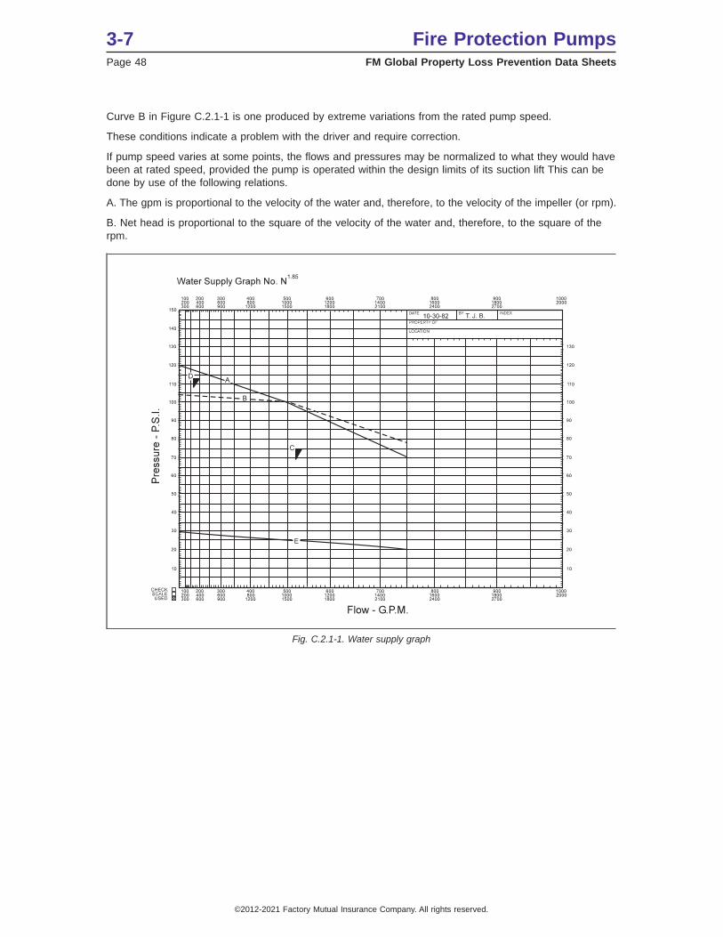
Curve B in Figure C.2.1-1 is one produced by extreme variations from the rated pump speed.
These conditions indicate a problem with the driver and require correction.
If pump speed varies at some points, the flows and pressures may be normalized to what they would havebeen at rated speed, provided the pump is operated within the design limits of its suction lift This can bedone by use of the following relations.
A. The gpm is proportional to the velocity of the water and, therefore, to the velocity of the impeller (or rpm).
B. Net head is proportional to the square of the velocity of the water and, therefore, to the square of therpm.
Fig. C.2.1-1. Water supply graph
3-7 Fire Protection PumpsPage 48 FM Global Property Loss Prevention Data Sheets
©2012-2021 Factory Mutual Insurance Company. All rights reserved.

Fig. C.2.1-2. Effect of variations in speed on pump performance curve
Fire Protection Pumps 3-7FM Global Property Loss Prevention Data Sheets Page 49
©2012-2021 Factory Mutual Insurance Company. All rights reserved.