AC8499 A-C Fire Pumps -...
28
A-C Fire Pump A-C Model FP A-C Fire Pumps Vertical Turbine Fire Pump Installation, Operation and Maintenance Instructions INSTALLER: PLEASE LEAVE THIS MANUAL FOR THE OWNER’S USE. AC8499
Transcript of AC8499 A-C Fire Pumps -...

A-C Fire Pump
A-C Model FP
A-C Fire PumpsVertical Turbine Fire Pump
Installation, Operation and Maintenance Instructions
INSTALLER: PLEASE LEAVE THIS MANUAL FOR THE OWNER’S USE.
AC8499
2
Safety Apparel:
• Insulated work gloves when handling hot bearings or usingbearing heater.
• Heavy work gloves when handling parts with sharp edges,especially impellers.
• Safety glasses (with side shields) for eye protection, espe-cially in machine shop areas.
• Steel-toed shoes for foot protection when handling parts,heavy tools, etc.
• Other personal protective equipment to protect againsthazardous/toxic fluid.
Coupling Guards:
• Never operate a pump without a coupling guard properlyinstalled.
Flanged Connections:
• Never force piping to make a connection with a pump.
• Use only fasteners of the proper size and proper material.
• Ensure there are no missing fasteners.
• Beware of corroded or loose fasteners.
• Do not operate below minimum rated flow, or with suction/discharge valves closed.
• Do not open vent or drain valves, or remove plugs whilesystem is pressurized.
Maintenance Safety:
• Always lock out power.
• Ensure pump is isolated from system and pressure isrelieved before disassembling pump, removing plugs, ordisconnecting piping.
• Use proper lifting and supporting equipment to preventserious injury.
• Observe all decontamination procedures.
• Know and follow company safety regulations.
Pump Safety Tips
Note: Observe all cautions and warnings highlightedin the pump Installation, Operation and MaintenanceInstructions.
3
FOREWORDThis manual provides instructions for the Installation, Opera-tion, and Maintenance of the A-C Fire Pumps. This manualcovers a standard product. For special options, supplementalinstructions are available. This manual must be read andunderstood before installation and start-up.
This instruction manual covers several different pump models.Most assembly, disassembly, and inspection procedures arethe same for all the pumps. However, where there are differ-ences, these differences will be noted within the manual. Thedesign, materials, and workmanship incorporated in the con-struction of the A-C Fire Pumps makes them capable of givinglong, trouble-free service. The life and satisfactory service ofany mechanical unit, however, is enhanced and extended bycorrect application, proper installation, periodic inspection,condition monitoring and careful maintenance. This instructionmanual was prepared to assist operators in understanding theconstruction and the correct methods of installing, operating,and maintaining these pumps.
The information contained in this book is intended to assistoperating personnel by providing information on the charac-
teristics of the purchased equipment. It does not relieve theuser of their responsibility of using accepted engineeringpractices in the installation, operation, and maintenance ofthis equipment.
A-C Fire Pumps shall not be liable for physical injury,damage, or delays caused by a failure to observe theinstructions for installation, operation, and maintenancecontained in this manual.
Warranty is valid only when genuine A-C Fire Pumps partsare used.
Use of the equipment on a service other than stated in theorder will nullify the warranty, unless written approval isobtained in advance from A-C Fire Pumps.
For information or questions not covered in this manual, con-tact A-C Fire Pump Systems at (847) 966-3700.
THIS MANUAL EXPLAINS
• Proper Installation• Start-up Procedures• Operation Procedures• Routine Maintenance• Pump Overhaul• Trouble Shooting• Ordering Spare or Repair Parts
4
Warranty
WARRANTY – Company warrants title to the product(s)and, except as noted with respect to items not of Company’smanufacturer, also warrants the product(s) on date of ship-ment to Purchaser, to be of the kind and quality describedherein, and free of defects in workmanship and material.THIS WARRANTY IS EXPRESSLY IN LIEU OF ALLOTHER WARRANTIES, INCLUDING BUT NOT LIMITEDTO IMPLIED WARRANTIES OF MERCHANTABILITYAND FITNESS, AND CONSTITUTES THE ONLY WARRANTY OF COMPANY WITH RESPECT TO THEPRODUCT(S).
If within one year from date of initial operation, but not morethan 18 months from date of shipment by Company of anyitem of product(s), Purchaser discovers that such item wasnot as warranted above and promptly notifies Company inwriting thereof, Company shall remedy such nonconformanceby, at Company’s option, adjustment or repair or replacementof the item and any affected part of the product(s). Purchasershall assume all responsibility and expense for removal, re-installation, and freight in connection with the foregoing remedies. The same obligations and conditions shall extendto replacement parts furnished by Company hereunder.Company shall have the right of disposal of parts replaced byit. Purchaser agrees to notify Company, in writing, of anyapparent defects in design, material or workmanship, prior to
performing any corrective action back-chargeable to theCompany. Purchaser shall provide a detailed estimate forapproval by the Company.
ANY SEPARATE LISTED ITEM OF THE PRODUCT(S)WHICH IS NOT MANUFACTURED BY THE COMPANYIS NOT WARRANTED BY COMPANY and shall be covered only by the express warranty, if any, of the manufac-turer thereof.
THIS STATES THE PURCHASER’S EXCLUSIVEREMEDY AGAINST THE COMPANY AND ITS SUP-PLIERS RELATING TO THE PRODUCT(S), WHETHERIN CONTRACT OR IN TORT OR UNDER ANY OTHERLEGAL THEORY, AND WHETHER ARISING OUT OFWARRANTIES, REPRESENTATIONS, INSTRUC-TIONS, INSTALLATIONS OR DEFECTS FROM ANYCAUSE.
Company and its suppliers shall have no obligation as toany products which has been improperly stored or han-dled, or which has not been operated or maintainedaccording to instructions in Company or supplier fur-nished manuals.
ITT AC Fire Pump Systems
5
Job Specific Table of Contents
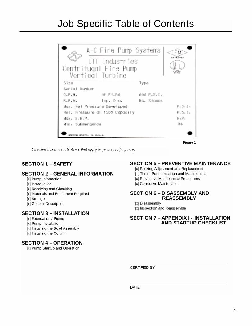
Figure 1
Checked boxes denote items that apply to your specific pump.
SECTION 1 – SAFETY
SECTION 2 – GENERAL INFORMATION[x] Pump Information[x] Introduction[x] Receiving and Checking[x] Materials and Equipment Required[x] Storage[x] General Description
SECTION 3 – INSTALLATION[x] Foundation / Piping[x] Pump Installation[x] Installing the Bowl Assembly[x] Installing the Column
SECTION 4 – OPERATION[x] Pump Startup and Operation
SECTION 5 – PREVENTIVE MAINTENANCE[x] Packing Adjustment and Replacement[ ] Thrust Pot Lubrication and Maintenance[x] Preventive Maintenance Procedures[x] Corrective Maintenance
SECTION 6 – DISASSEMBLY AND REASSEMBLY
[x] Disassembly[x] Inspection and Reassemble
SECTION 7 – APPENDIX I - INSTALLATION AND STARTUP CHECKLIST
________________________________
CERTIFIED BY
DATE
6
SECTION 1 - SAFETY Page Definitions . . . . . . . . . . . . . . . . . . . . . . . . . . . . . . . . . . . . . . . . . . . . . . . . . . . . . . . . . . . . . . . . . . . . . 7General Precautions . . . . . . . . . . . . . . . . . . . . . . . . . . . . . . . . . . . . . . . . . . . . . . . . . . . . . . . . . . . . . 7
SECTION 2 - GENERAL INFORMATIONIntroduction . . . . . . . . . . . . . . . . . . . . . . . . . . . . . . . . . . . . . . . . . . . . . . . . . . . . . . . . . . . . . . . . . . . . 8Receiving & Checking . . . . . . . . . . . . . . . . . . . . . . . . . . . . . . . . . . . . . . . . . . . . . . . . . . . . . . . . . . . . 8Materials & Equipment Required . . . . . . . . . . . . . . . . . . . . . . . . . . . . . . . . . . . . . . . . . . . . . . . . . . . . 8Storage . . . . . . . . . . . . . . . . . . . . . . . . . . . . . . . . . . . . . . . . . . . . . . . . . . . . . . . . . . . . . . . . . . . . . . . 8General Description . . . . . . . . . . . . . . . . . . . . . . . . . . . . . . . . . . . . . . . . . . . . . . . . . . . . . . . . . . . . . . 9
SECTION 3 - INSTALLATIONFoundation/Piping . . . . . . . . . . . . . . . . . . . . . . . . . . . . . . . . . . . . . . . . . . . . . . . . . . . . . . . . . . . . . . . 10Pump Installation . . . . . . . . . . . . . . . . . . . . . . . . . . . . . . . . . . . . . . . . . . . . . . . . . . . . . . . . . . . . . . . . 11Installing the Bowl Assembly . . . . . . . . . . . . . . . . . . . . . . . . . . . . . . . . . . . . . . . . . . . . . . . . . . . . . . 11Installing the Column . . . . . . . . . . . . . . . . . . . . . . . . . . . . . . . . . . . . . . . . . . . . . . . . . . . . . . . . . . . . . 12Installing the Discharge Head . . . . . . . . . . . . . . . . . . . . . . . . . . . . . . . . . . . . . . . . . . . . . . . . . . . . . . 13Stuffing Box Installation . . . . . . . . . . . . . . . . . . . . . . . . . . . . . . . . . . . . . . . . . . . . . . . . . . . . . . . . . . 13Installing the Driver . . . . . . . . . . . . . . . . . . . . . . . . . . . . . . . . . . . . . . . . . . . . . . . . . . . . . . . . . . . . . . 14
SECTION 4 - OPERATIONPump Startup & Operation . . . . . . . . . . . . . . . . . . . . . . . . . . . . . . . . . . . . . . . . . . . . . . . . . . . . . . . . 16
SECTION 5 - PREVENTIVE MAINTENANCEPacking Adjustment & Replacement . . . . . . . . . . . . . . . . . . . . . . . . . . . . . . . . . . . . . . . . . . . . . . . . . 16Thrust Pot Lubrication & Maintenance . . . . . . . . . . . . . . . . . . . . . . . . . . . . . . . . . . . . . . . . . . . . . . . 17Preventive Maintenance Procedures . . . . . . . . . . . . . . . . . . . . . . . . . . . . . . . . . . . . . . . . . . . . . . . . 17Corrective Maintenance . . . . . . . . . . . . . . . . . . . . . . . . . . . . . . . . . . . . . . . . . . . . . . . . . . . . . . . . . . 18
SECTION 6 - DISASSEMBLY & REASSEMBLYDisassembly . . . . . . . . . . . . . . . . . . . . . . . . . . . . . . . . . . . . . . . . . . . . . . . . . . . . . . . . . . . . . . . . . . . 19Inspection & Reassembly . . . . . . . . . . . . . . . . . . . . . . . . . . . . . . . . . . . . . . . . . . . . . . . . . . . . . . . . . 20
SECTION 7 - REPAIR PARTSRepair Parts . . . . . . . . . . . . . . . . . . . . . . . . . . . . . . . . . . . . . . . . . . . . . . . . . . . . . . . . . . . . . . . . . . . . 22
SECTION 8 - APPENDIX IInstallation & Startup Checklist . . . . . . . . . . . . . . . . . . . . . . . . . . . . . . . . . . . . . . . . . . . . . . . . . . . . 25
Index
7
Section 1 - Safety
These pumps have been designed for safe and reliableoperation when property used and maintained in accordancewith instructions contained in this manual. A pump is a pres-sure containing device with rotating parts that can be haz-ardous. Operators and maintenance personnel must realizethis and follow safety measures. A-C Fire Pumps shall not beliable for physical injury, death, damage or delays caused bya failure to observe the instructions in this manual.
Throughout this manual the words WARNING, CAUTION,and NOTE are used to indicate procedures or situationswhich require special operator attention:
NOTE: Operating procedure, condition, etc. which is essentialto observe.
EXAMPLES:
• NEVER apply heat to remove impeller. It may explodedueto trapped liquid.
• NEVER use heat to disassemble pump due to risk ofexplosion from trapped liquid.
• NEVER operate pump without coupling guard correclyinstalled.
• NEVER operate pump beyond the rated conditions towhich the pump was sold.
• NEVER start pump without proper prime (sufficient liquid inpump casing).
• NEVER run pump below recommended minimum flow orwhen dry.
• ALWAYS lock out power to the driver before performingpump maintenance.
• NEVER operate pump without safety devices installed.
• NEVER operate pump with discharge valve closed.
• NEVER operate pump with suction valve closed.
• DO NOT change conditions of service without approval ofan authorized A-C Fire Pumps representative.
Definitions
General Precautions
WARNING: Operating procedure, practice, etc., which,if not correctly followed, could result in personal injury
or loss of life.
CAUTION: Operating procedure, practice, etc. which, if not followed, could result in damage or destruction
of equipment.
WARNING: Personal injuries will result if procedures outlined in this manual are not followed.
CAUTION: Throttling flow from the suction side may cause cavitation and pump damage. NOTE: Proper
alignment is essential for long pump life.
WARNING: Pump shall never be operated withoutcoupling guard installed correctly.
8
The pump should be carefully supported prior to unloadingfrom the carrier. Handle all components carefully. Inspectionfor damage of the shipping crate should be made prior tounpacking the pump. After unpacking, visually inspect thepump and check the following:
1. Contents of the pump assembly against the packing list.
2. All components against damage.
3. All shafting for straightness and damage, should the cratebe broken or show careless handling.
Any shortages or damages should be immediately called tothe attention of the local freight agent of the carrier by whichthe shipment arrived and proper notation made on the bill.This will prevent any controversy when claim is made andfacilitate prompt and satisfactory adjustment
Receiving & Checking
Materials & Equipment Required
The material and equipment necessary for installation of thepump will vary with the size of the pump and the type ofinstallation.
The following list of standard tools and supplies is offeredonly as a guide.
BULK MATERIAL
• Anti-Gall ing lubricant (such as Dow Corning"MOLYKOTE")
• Thread Compound
• Lubrication Oil
• Turbine Oil
Grease
RIGGING EQUIPMENT
• Mobile power hoist, traveling crane, or derrick
• Drag line and blocks
• Elevator clamps, if unit is unassembled
• Clevises – for use with eyebolts
• Timbers – size, length, and quantity to support long pumpparts on the floor
• I-Beams or timbers to support pump over installation
HAND TOOLS
• Pipe wrenches
• Feeler gauges
• Set of mechanics tools including: files, wire brush, pliers,wire cutters and pocket knife
• Clean rags
OPTIONAL TOOLS TO FACILITATE PUMP ASSEMBLYAND DISASSEMBLY
• Dial indicator to assist in motor and pump alignment
• Collet driver to assist in bowl assembly and disassemblyfor pumps with taper lock impellers only
StorageA-C Fire Pumps carefully preserves and protects its productsfor shipment. However, the effective life of the preservativesapplied at the factory can vary from 3 to 18 months dependingon the severity of the environment in which the equipment isstored. This section provides procedures for preparation priorto storage and maintenance during storage of A-C FirePumps. These procedures are necessary to protect the preci-
sion parts of the pumps. Specific procedures for storingmotors, gearheads, and engines, should be obtained from theequipment manufacturer. This section is intended to be ofgeneral assistance to users of A-C Fire Pumps. It shall notmodify, amend and/or otherwise alter the scope of A-C FirePumps warranty responsibilities to the purchaser in any waywhatsoever.
Section 2 - General InformationIntroduction
The design, material, and workmanship incorporated in theconstruction of A-C Fire Pumps makes them capable of givinglong, trouble free service. The life and satisfactory service ofany mechanical unit, however, is enhanced and extended bycorrect application, proper installation, periodic inspectionand careful maintenance. This instruction manual was pre-pared to assist operators in understanding the constructionand the correct methods of installing, operating, and maintain-ing these pumps.
Study thoroughly Sections 1 through 6 and carefully follow theinstructions for installing and operating. Sections 5 containsanswers to trouble shooting and maintenance questions.Keep this instruction manual handy for reference.
CAUTION: The information in this manual is intended to be used as a guide only. If you are in doubt, con-
sult your A-C Fire Pumps representative for specific infor-mation about your pump.
WARNING: Rotating components of the pumpassembly must be covered with a suitable rigid guard
to prevent injury to personnel.
WARNING: A-C Fire Pumps will not be liable for any damages or delay caused by failure to comply with
the provisions of this instruction manual.
9
STORAGE PREPARATION
A-C Fire Pumps require proper preparation for storage andregular maintenance during storage. The pump shall be con-sidered in storage when it has been delivered to the job siteand is awaiting installation.
Preferably, the storage area shall be paved, well drained andfree from flooding, and be indoors whenever possible.
Weatherproof coverings used for outdoor storage shall beflame resistant type sheeting or tarpaulins. They shall beplaced so as to provide good drainage and air circulation andshall be tied down to protect from wind damage.
Storage area shall be maintained in a clean condition at alltimes.
Pumps and/or component parts shall be placed on skids,pallets, or shoring to permit good air circulation.
Pumps and/or component parts shall be sorted so as to per-mit ready access for inspection and/or maintenance withoutexcessive handling.
Pumps and/or component parts stacked during storage shallbe arranged so that the racks, containers, or crates bear fullweight without distortion of pumps or parts. Identificationmarkings must be readily visible. Any cover removed for inter-nal access shall be replaced immediately.
Pump and bowl assembly shafting shall be rotated counterclockwise, as a minimum, once a month. Shaft shall not be leftin the same previous position, nor in the extreme raised orlowered lateral position. Shaft should rotate freely.
NOTE: For further information on these procedures con-tact your A-C Fire Pumps representative.
RECOMMENDED STORAGE PROCEDURES
Controlled storage facilities should be maintained at an eventemperature 10ºF (6ºC) or more above the dew point with
relative humidity less than 50% and little or no dust. (If theserequirements can not be met the pump is to be considered inuncontrolled storage.)
For uncontrolled storage periods of 6 months or less, thepump is to be inspected periodically to insure that all preserv-atives are intact.
All pipe threads and flanged pipe covers are to be sealed withtape.
The pump must not be stored closer than six inches (15 cm)from the ground.
UNCONTROLLED LONG TERM STORAGEPREPARATIONS
When applicable to the pump, storage periods over sixmonths require the preceding storage procedure and storagepreparation plus the following:
Inspect the lube oil and seal flush piping and either fill the pip-ing with rust preventative oil, or re-coat the piping periodicallyto prevent corrosion.
Place 10 pounds (4.5 kg) of moisture absorbing desiccant or5 pounds (2.3 kg) of vapor phase inhibitor crystals near thecenter of the pump. If the pump is assembled, place an addi-tional one pound (0.5 kg) in the discharge nozzle securely fas-tened to the discharge elbow.
Install a moisture indicator near the perimeter of the pump.Cover the pump with 6 mil (0.15 mm) minimum thicknessblack polyethylene or equal and seal it with tape. Provide asmall ventilation hole approximately 1/2 inch (12 mm) diameter.
Provide a roof or shed shelter to protect from direct exposureto the elements.
General DescriptionThe model FP pump is a vertical turbine fire pump, which isdesigned to meet many wide ranges of service.
DRIVERS
When packed stuffing boxes are used with open lineshaftpumps, hollow shaft motors or right angle gear drives, areoften used with a separate driveshaft through the driver andconnected to the pump by a rigid coupling.
DISCHARGE HEAD
The discharge head is either a cast iron head or a fabricated‘F’ type head. Ports are provided for connecting the dischargegauge and stuffing box bypass return. The driver support por-tion of the discharge head is designed with large hand holesfor easy mechanical seal or stuffing box adjustment.
COLUMN
Threaded or flanged column construction provides positiveshaft and bearing alignment. Bearings are spaced to providevibration free operation. This will insure long bearing life andreduced shaft wear. The lineshaft is supported within the column by use of bearing retainers in the column assembly.
BOWL ASSEMBLY
The bowls are generally of flanged construction for accuratealignment and ease of assembly and disassembly. Impellersare enclosed. For temperatures over 180ºF (82ºC) and in thelarger size bowls, impellers are keyed to the shaft.
THRUST POT
A thrust pot is utilized when the driver is not designed to carrythe pump thrust.
BASE (SOLE PLATE) INSPECTION
Sub Base and Sole Plate are terms in common use to de-scribe a general class of solid steel plates mounted in grout(or bolted to steel structures) at the pump-foundation interface.
1. Remove the Sub Base from the Pump Discharge Head,when shipped assembled.
2. Completely clean the underside of the Sub Base. It issometimes necessary to coat the underside of the SubBase with an epoxy primer. (This is available as an option.)
3. Remove the rust preventative solution from the machinedtopside with an appropriate solution.
SITE WITH CONCRETE FOUNDATION
1. A pump should have adequate space for operation, maintenance, and inspection.
2. Sub Base mounted pumps are normally grouted on a con-crete foundation, which has been poured on a solid foot-ing. The foundation must be able to absorb any vibrationand to form a permanent, rigid support for the pumpingunit.
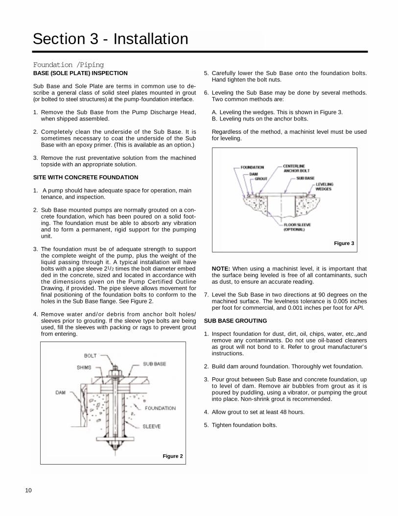
3. The foundation must be of adequate strength to supportthe complete weight of the pump, plus the weight of theliquid passing through it. A typical installation will havebolts with a pipe sleeve 21/2 times the bolt diameter embedded in the concrete, sized and located in accordance withthe dimensions given on the Pump Certified OutlineDrawing, if provided. The pipe sleeve allows movement forfinal positioning of the foundation bolts to conform to theholes in the Sub Base flange. See Figure 2.
4. Remove water and/or debris from anchor bolt holes/sleeves prior to grouting. If the sleeve type bolts are beingused, fill the sleeves with packing or rags to prevent groutfrom entering.
5. Carefully lower the Sub Base onto the foundation bolts.Hand tighten the bolt nuts.
6. Leveling the Sub Base may be done by several methods.Two common methods are:
A. Leveling the wedges. This is shown in Figure 3.B. Leveling nuts on the anchor bolts.
Regardless of the method, a machinist level must be used for leveling.
NOTE: When using a machinist level, it is important that the surface being leveled is free of all contaminants, such as dust, to ensure an accurate reading.
7. Level the Sub Base in two directions at 90 degrees on themachined surface. The levelness tolerance is 0.005 inchesper foot for commercial, and 0.001 inches per foot for API.
SUB BASE GROUTING
1. Inspect foundation for dust, dirt, oil, chips, water, etc.,andremove any contaminants. Do not use oil-based cleanersas grout will not bond to it. Refer to grout manufacturer’sinstructions.
2. Build dam around foundation. Thoroughly wet foundation.
3. Pour grout between Sub Base and concrete foundation, upto level of dam. Remove air bubbles from grout as it ispoured by puddling, using a vibrator, or pumping the groutinto place. Non-shrink grout is recommended.
4. Allow grout to set at least 48 hours.
5. Tighten foundation bolts.
10
Section 3 - Installation
Foundation /Piping
Figure 2
Figure 3
11
SITE WITH STRUCTURAL STEEL FOUNDATION
1. When the pump is mounted directly on a structural steelframe, pumps shall be located directly over, or as near aspossible to the main building members, beams, or walls.be bolted to the support to avoid distortion, prevent vibra-tion, and retain proper alignment.
2. If a Sub Base is being bolted to a structural steel founda-tion, or the Sub Base is not grouted to the concrete foun-dation, use shims for leveling the plate.
PIPING
Guidelines for piping are given in the "Hydraulic InstituteStandards", available from: Hydraulic Institute, 9 Sylvan Way,Parisppany, NJ 07054-3802 and must be reviewed prior topump installation.
1. All piping must be supported independently of, and line upnaturally with, the pump flange.
2. DO NOT connect piping to pump until grout has hardened and pump hold down bolts have been tightened.
3. It is suggested that expansion loops or joints, if used, beproperly installed in discharge line when handling liquids atelevated temperatures, so linear expansion of piping willnot draw pump out of alignment.
4. Carefully clean all pipe parts, valves and fittings, and pumpbranches prior to assembly.
5. Isolation and check valves should be installed in dischargeline. Locate the check valve between isolation valve andpump, this will permit inspection of the check valve. Theisolation valve is required for regulation of flow, and forinspection and maintenance of pump. The check valveprevents pump or seal damage due to reverse flow throughthe pump when the driver is turned off.
6. Increasers, if used, should be placed between pump andcheck valves.
7. Cushioning devices should be used to protect the pumpfrom surges and water hammer if quick-closing valves areinstalled in the system.
FINAL PUMP CHECK
1. Rotate shaft several times by hand to be sure that there isno binding and all parts are free.
2. Check alignment, per the alignment procedure outlined onpage 16, to determine absence of pipe strain. If pipe strainexists, correct piping.
Pump InstallationPumps 20 feet (6m) or less in length are usually shippedassembled, with the exception of the driver and packing.When provided, refer to the Certified Pump Outline for theapplicable base plate plan for location of anchor bolt holes.
INSTALLING A PARTIALLY ASSEMBLED PUMP
1. If a baseplate was supplied, install as described inFoundation/Piping Section page 10.
2. Clean the plate mounting flange and clean bottom surfaceof discharge head mounting flange.
3. Sling through discharge hand holes or thread two eyeboltsthrough bolt holes in mounting flange and hoist unit intoposition over foundation.
NOTE: Eyebolts or sling should be rated to handle in excessof the pump weight (see Order Outline Drawing, if provided).
4. Lower the unit and carefully guide it so that unit does notstrike the sides of the base plate. Continue to lower unituntil the discharge head base flange engages and restsfirmly on the plate, then secure with capscrews provided.
5. When a lineshaft is shipped separately check shaft forstraightness; average total runout should not exceed0.005" T.I.R. (0.127mm) for every 10 feet (3m). Shaftstraightness must be within tolerance prior to installation.
6. Remove stuffing box (if installed), and carefully slide shaftthrough top column bearing retainer and thread into cou-pling after replacing stuffing box or seal housing.Useextreme care not to damage bearing retainer.
7. Refer to the remainder of this manual for complete assem-bly, startup, maintenance, disassembly, and recommendedlubricants for the pump.
Installing Bowl AssemblyThe following bowl installation instructions apply to pumpsshipped disassembled.
1. Prior to installing the bowl assembly, check that all cap-screws are tight and any integral piping is installed.Remove all accumulated dust, oil, or other foreign materialfrom the external surfaces.
WARNING: Never draw piping into place by forcing at the flange connections of the pump. Pipe strain will
adversely effect the operation of the pump resulting in phys-ical injury and damage to the equipment.
WARNING: Do not work under a heavy suspended object unless there is positive support and safe guards
which will protect personnel should a hoist or sling fail.
CAUTION: Do not attempt to lift bowl assembly by the pump shaft. This can result in damaging the pump
shaft.
12
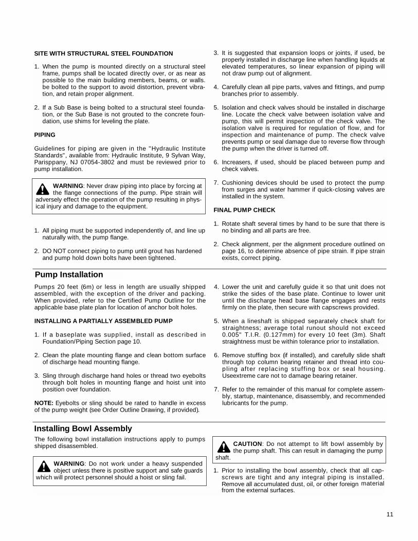
2. Place two I-beam supports across the base plate opening,strong enough to safely support the weight of the entirepump assembly. These I-beams should be connected bythreaded rods and nuts, so as to clamp them firmly togetherfor the portion to be supported. (See Figure 4).
3. Put in place a suitable hoist or derrick over base plateopening. Place the elevator clamps just below the dichargebowl flange or install two threaded eye bolts through boltholes in flange 180º apart.
4. Attach sling to elevator clamps or eye bolts and hoist intoposition over foundation opening (See Figure 4).
5. Carefully lower bowl assembly, guiding the unit so it doesnot strike the sides of the opening. Continue to lower bowlassembly until the elevator clamps or discharge bowlflange rests firmly on the I-beam supports.
6. Place a cover over the discharge bowl opening to prevententrance of dirt or other foreign matter.
Figure 4
Installing the Column
OPEN LINESHAFT
Pump lineshafts are connected with threaded couplings.When provided, see the Certified Pump Outline Drawing forthe number of column and shaft sections required:
1. Check the headshaft (608) and lineshaft (646) for straight-ness. Average total runout should be less than 0.0005" TIR(0.013 mm) per foot (0.305 m), not to exceed 0.005" T.I.R.(0.127 mm) for every 10 feet (3 m) of shafting.
2. Apply a thin film of oil to lineshaft (646) and coupling (649)threads (in non-galling material, or Molykote if gallingmaterial). Start threads manually until resistance is felt. Afine wire inserted in the drill hole at the center of the cou-pling can be used as a gauge to determine when the cou-pling is correctly positioned on the shaft. Run the upperlineshaft into the coupling until it is hand tight. Remove thewire after installing the coupling. Complete the joint using apair of pipe wrenches, one on the top of pump shaft (660)and the other on the coupling (649).
3. Use chain wrenches (clamp type) attached to the shaft totighten the two shafts, using care not to damage any bear-ing journal areas. NOTE: Shaft threads are left-handed.
4. Hoist column section over bowl assembly. Lower columnover lineshaft until column flange engages the dischargebowl. Manually thread the column into the discharge bowl.
Complete joint by tightening column with chain tongs untilthe end of the column butts firmly against discharge bowl.
5. For flanged column, install two eyebolts diametricallyopposite the upper flange of the bottom volume. Attach asling to the eyebolts and to the hoist hook.
Lower column section until the flange engages the flangedtop bowl register. Insert as many bolts through bothflanges as possible. Lift column assembly high enough toallow rotation of the supports. Install and tighten remainingcapscrews gradually in diametrically opposite pairs until allare uniformly tight.
6. Lift the assembly and remove the elevator clamp or sup-ports and slowly lower the bowl and column assembly.Place supports on the base plate and continue to lower theassembly until the column elevator clamps or colum flangecomes to rest on the supports. Place an elevator clampunder the column pipe and allow it to butt firmly againstthe column pipe coupling
7. Place the bearing retainer over the shaft and locate it in thecolumn coupling recess.
Flanged columns will normally have separate bearingsretailers, which will fit into the female registers in theflanges on both ends of the column. Large flange columnwill have the bearing retainer integral with the column. Thetop flange of the column will have a male register and thebottom flange of the column will have a female register.
For metal bearings, pour a small amount of oil between thebearing and shaft. Install threaded coupling on protrudingend of lineshaft.
8. Repeat the preceding procedures until all column sectionsrequired have been installed. For deeper set pump units, astub shaft will be the top shaft.
CAUTION: Do not drop any foreign object into thebowl assembly. Such an object can cause serious
damage to the pump and any downstream componentsAny foreign object dropped into the bowl assembly must beretrieved prior to continuing assembly.
CAUTION: Use "MOLYKOTE" Dow-Corning or equal for all galling material such as 316 stainless steel.
13
Installing the Discharge HeadOPEN LINESHAFT
1. A-C Fire Pumps are provided with either a cast iron or fabsteel type head. Install the discharge head as follows:
2. If the stuffing box is assembled to the head, remove it andall attached piping. See Figure 5 for the stuffing box pro-vided for the A-C Fire Pump being assembled.
3. Remove coupling guard if provided. Attach a sling throughwindows (hand holes) or thread two eyebolts in the headdriver support mounting holes diametrically opposite andhoist discharge head over the protruding headshaft.
4. Orient the discharge head in the required position andlower the head, centering the vertical hole with the head-shaft or stub shaft protruding above the column. Forthreaded column, continue to lower the discharge headuntil the large threaded hole in the bottom of the dischargehead rests squarely on top of the column. Rotate the dis-charge head, screwing it onto the column, butting the topof the column tightly against the discharge head.
5. For flanged column, continue to lower the discharge headuntil the discharge head engages the column. Install cap-screws and secure discharge head to the column flange.Tighten capscrews gradually in diametrically oppositepairs.
6. Lift pump assembly high enough to allow rotation of thesupports. Realign and lower assembly. Install and tightenremaining capscrews. Repeat rotation and tightening pro-cedure, until all capscrews are uniformly tight.
7. Using a device with the capacity to support the weight ofthe entire pump assembly, hoist bowl, column, and headassembly and remove supports.
NOTE: Eyebolts or sling should be rated to handle inexcess of the pump weight.
8. Lower bowl, column and head assembly, until dischargehead mounting flange engages base plate. Secure dis-charge head to mounting plate. Check the levelness of thedischarge head in all directions, utilizing a spirit levelacross the driver mounting surface of the discharge head.
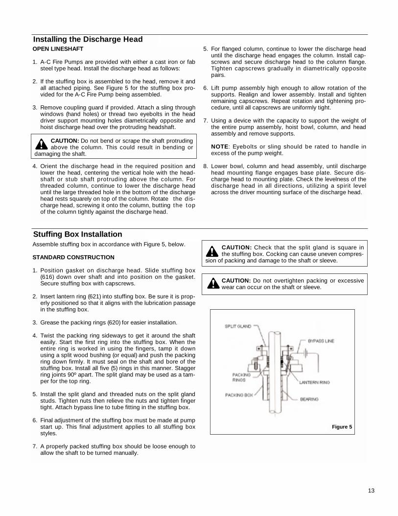
Stuffing Box InstallationAssemble stuffing box in accordance with Figure 5, below.
STANDARD CONSTRUCTION
1. Position gasket on discharge head. Slide stuffing box(616) down over shaft and into position on the gasket.Secure stuffing box with capscrews.
2. Insert lantern ring (621) into stuffing box. Be sure it is prop-erly positioned so that it aligns with the lubrication passagein the stuffing box.
3. Grease the packing rings (620) for easier installation.
4. Twist the packing ring sideways to get it around the shafteasily. Start the first ring into the stuffing box. When theentire ring is worked in using the fingers, tamp it downusing a split wood bushing (or equal) and push the packingring down firmly. It must seal on the shaft and bore of thestuffing box. Install all five (5) rings in this manner. Staggerring joints 90º apart. The split gland may be used as a tam-per for the top ring.
5. Install the split gland and threaded nuts on the split glandstuds. Tighten nuts then relieve the nuts and tighten fingertight. Attach bypass line to tube fitting in the stuffing box.
6. Final adjustment of the stuffing box must be made at pumpstart up. This final adjustment applies to all stuffing boxstyles.
7. A properly packed stuffing box should be loose enough toallow the shaft to be turned manually.
Figure 5
CAUTION: Do not bend or scrape the shaft protrudingabove the column. This could result in bending or
damaging the shaft.
CAUTION: Check that the split gland is square inthe stuffing box. Cocking can cause uneven compres-
sion of packing and damage to the shaft or sleeve.
CAUTION: Do not overtighten packing or excessivewear can occur on the shaft or sleeve.
INSTALLATION OF A HOLLOW SHAFT DRIVER
This refers to either VHS type electric motors or hollow shafttype gear drives.A small paragraph will be devoted to combi-nation electric motor and right angle gear drives.
NOTE: When pump is supplied with a thrust pot, do notsecure driver to discharge head until after the thrust pot andflexible coupling are installed.
1. The driveshaft projecting through the quill or hollow-shaftof the driver is separate from the pump shaft and con-nected to same by a rigid flanged coupling or threadedcoupling.
2. Driver support. When a driver support is furnished and notinstalled, proceed as follows:
A. Hoist driver support, inspect the mounting surfaces,register, and clean these surfaces thoroughly.
B. Install driver support on discharge head and secure withcapscrews provided.
3. Attach a sling to the lifting lugs of driver, hoist motor,inspect the mounting surface, register, and shaft exten-sion, and clean these surfaces thoroughly. If any burrs arefound, remove burrs with a smooth mill file, cleaning thor-oughly afterward.
4. Orient the motor conduit box in the required position. Alignthe motor mounting holes with the mating tapped holes onthe discharge head. Lower the motor until the registersengage and the motor rests on the discharge head. Securemotor with capscrews provided.
5. On drivers having a non-reverse ratchet or pins, manuallyturn the driver shaft clockwise viewed from the top until thenon-reverse ratchet or pins fully engage.
6. Lubricate motor bearings in accordance with instructionsgiven on lubrication plate attached to the motor case.
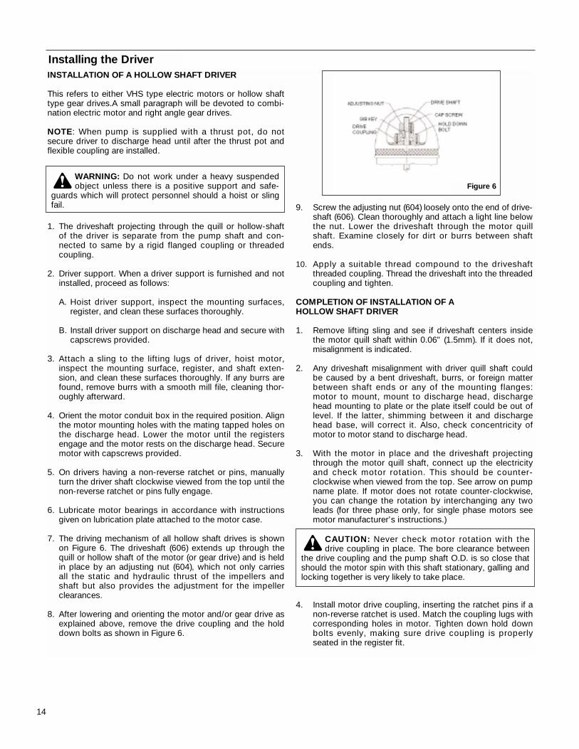
7. The driving mechanism of all hollow shaft drives is shownon Figure 6. The driveshaft (606) extends up through thequill or hollow shaft of the motor (or gear drive) and is heldin place by an adjusting nut (604), which not only carriesall the static and hydraulic thrust of the impellers andshaft but also provides the adjustment for the impellerclearances.
8. After lowering and orienting the motor and/or gear drive asexplained above, remove the drive coupling and the holddown bolts as shown in Figure 6.
9. Screw the adjusting nut (604) loosely onto the end of drive-shaft (606). Clean thoroughly and attach a light line belowthe nut. Lower the driveshaft through the motor quillshaft. Examine closely for dirt or burrs between shaftends.
10. Apply a suitable thread compound to the driveshaftthreaded coupling. Thread the driveshaft into the threadedcoupling and tighten.
COMPLETION OF INSTALLATION OF A HOLLOW SHAFT DRIVER
1. Remove lifting sling and see if driveshaft centers insidethe motor quill shaft within 0.06" (1.5mm). If it does not,misalignment is indicated.
2. Any driveshaft misalignment with driver quill shaft couldbe caused by a bent driveshaft, burrs, or foreign matterbetween shaft ends or any of the mounting flanges:motor to mount, mount to discharge head, dischargehead mounting to plate or the plate itself could be out oflevel. If the latter, shimming between it and dischargehead base, will correct it. Also, check concentricity ofmotor to motor stand to discharge head.
3. With the motor in place and the driveshaft projectingthrough the motor quill shaft, connect up the electricityand check motor rotation. This should be counter-clockwise when viewed from the top. See arrow on pumpname plate. If motor does not rotate counter-clockwise,you can change the rotation by interchanging any twoleads (for three phase only, for single phase motors seemotor manufacturer’s instructions.)
4. Install motor drive coupling, inserting the ratchet pins if anon-reverse ratchet is used. Match the coupling lugs withcorresponding holes in motor. Tighten down hold downbolts evenly, making sure drive coupling is properly seated in the register fit.
14
Installing the Driver
Figure 6WARNING: Do not work under a heavy suspendedobject unless there is a positive support and safe-
guards which will protect personnel should a hoist or slingfail.
CAUTION: Never check motor rotation with thedrive coupling in place. The bore clearance between
the drive coupling and the pump shaft O.D. is so close thatshould the motor spin with this shaft stationary, galling andlocking together is very likely to take place.
15
5. Fit gib key (760) into keyway, by filing if necessary, towhere there is a snug but sliding fit. This key must be ableto be removed by gentle leverage with a screwdriver under it.
6. Be careful that the gib key (760) is not too high so as tohold up the adjusting nut (604) from seating on the drivecoupling. If it is, cut off some of it.
7. Install adjusting nut (604) to hand tight.
GEAR DRIVES WITH ENGINES
1. The procedure for installing a hollow shaft gear is exactlythe same as for the motor.
2. Checking pump rotation is very simple matter. Check thearrows of rotation on the engine. Throw out the clutch, takea bar and jack over the flexible driveshaft in direction ofengine rotation, and note if it turns the pump shaft in theproper direction. Note: engines almost invariably turnclockwise when looking toward the gear drive.
COMBINATION ENGINE AND MOTOR DRIVES
1. On combination drivers, the motor is invariably on top witha projecting head shaft extension.
2. Follow all procedures outlined on page 19, except that themotor must be lowered over this extended driveshaft andgreat care must be taken to center it exactly so as not tobump or miss-align the shaft while the motor is beinglowered into place.
3. There are several methods of running engines withoutelectric motors and vise versa, requiring simple adjustmentto the combination drive, but they are too numerous tomention here and can be obtained from the gear manufac-turers instructions included with the shipment.
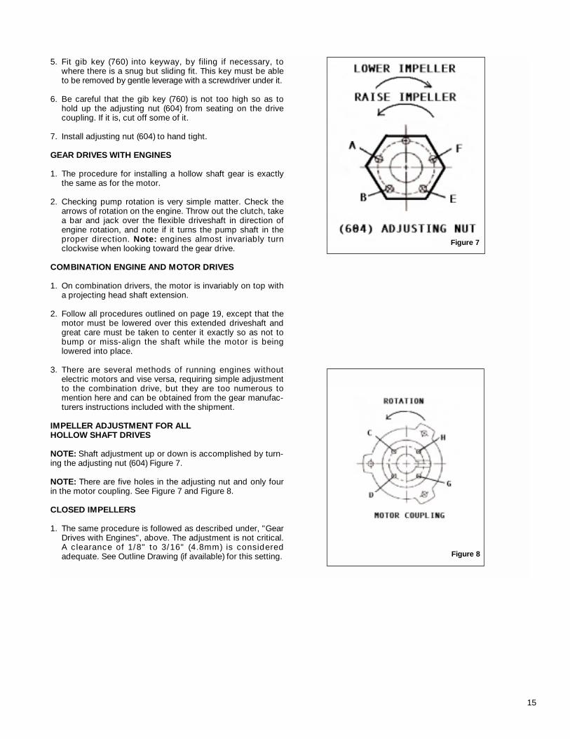
IMPELLER ADJUSTMENT FOR ALLHOLLOW SHAFT DRIVES
NOTE: Shaft adjustment up or down is accomplished by turn-ing the adjusting nut (604) Figure 7.
NOTE: There are five holes in the adjusting nut and only fourin the motor coupling. See Figure 7 and Figure 8.
CLOSED IMPELLERS
1. The same procedure is followed as described under, "GearDrives with Engines", above. The adjustment is not critical.A clearance of 1/8" to 3/16" (4.8mm) is consideredadequate. See Outline Drawing (if available) for this setting.
Figure 7
Figure 8
16
Section 4 - OperationPump Startup & Operation
PRE-START PROCEDURE
Consult the applicable manufacturer’s instructions for detailedinformation for the prime mover (electric motor, engine orsteam turbine), coupling, driveshaft, gear head or mechanicalseal. When applicable to the pump and prior to startup, checkthe following.
1. Confirm that the following procedures described in the"Installing the Drivers" sections have been performed:
A. Wiring of Driver.
B. Driver must rotate counterclockwise (CCW) when viewed from above.
C. Check alignment between pump and driver.
D. Impeller adjustment has been made.
E. Mechanical seal lock collar is attached to shaft.
2. Make sure mechanical seal is properly lubricated and allpiping to seal is connected. Also, check that all cooling,heating and flushing lines are operating and regulated.
3. All connections to driver and starting device match wiringdiagram.
4. Voltage, phase, and frequency on motor nameplate agreewith line current.
5. Rotate shaft manually to ensure impellers are not binding.
6. Verify that driver bearings are properly lubricated andcheck oil level in housing.
7. Check that auxiliary seal components are properly vented.
8. Inspect discharge piping connection and pressure gaugesfor proper operation.
PRECISION ALIGNMENT
A Precision Alignment Procedure, Section MA027, has beenwritten that describes our factory precision alignment.
PUMP STARTUP
1. Partially close valve in discharge line.
2. Crack open suction side valves on pressurized systemsslowly. Open suction valves fully.
3. Vent system when the pump surface temperature hasreached an equilibrium.
4. Start pump.
5. When pump is operating at full speed, slowly open dis-charge valve. If driver overheats or there is excessivevibration, stop the pump.
NOTE: If the impellers have not been finally adjusted, due to extreme liquid temperature, they should be adjustedprior to startup and after pump surface temperatureshave reached equilibrium.
STUFFING BOX
With the pump in operation, there should be some leakage atthe stuffing box packing. The correct leakage is a rate whichkeeps the shaft and stuffing box cool (approximately one dropper second). Check the temperature of the leakage as well asthe discharge head. If the pump runs hot and the leakagebegins to choke off, stop the pump and allow it to cool down.A few light taps with a hammer on the gland will
upset the packing sufficiently to resume leakage. After pumphas cooled, restart pump and follow preceding procedure.Run pump 15 minutes, check leakage, if it exceeds two dropsper second, adjust packing as described in "PackingAdjustment and Replacement" (page 17).
THRUST POT INSTALLATION
Thrust pots are not standard on most pumps. A separatesupplement will be inserted for pumps with thrust pots.
WARNING: Do not check motor rotation unlessmotor is bolted to pump and drive coupling is removed.
17
Pumps equipped with packing, shall be adjusted wheneverthe leakage rate exceeds two drops per second. If there is noleakage or the stuffing box overheats, stop the pump andallow packing to cool. Back off gland nuts. This will allow theentire set of rings to move away from the bottom of the box,without relieving pressure of the packing on the shaft. Restartthe pump. It may be necessary to repeat this procedure sev-eral times before proper amount of liquid comes through toefficiently prevent overheating. If leakage is excessive, adjustthe stuffing box as follows:
1. With the pump in operation, tighten the gland nuts one-quarter turn for each adjustment. Allow packing to equalizeagainst the increased pressure and leakage to grad-ually decrease to a steady rate, before making anotheradjustment.
2. With the pump shut down and when packing has beencompressed to the point that the gland is about to contactthe upper face of stuffing box, remove the split gland, addone extra packing ring and readjust. If this fails to reduceleakage to two drops per second, remove all packing ringsand replace with new rings.
3. Remove the packing with the aid of a packing hook. If alantern ring is provided, remove it by inserting a wire hookin the slots of the ring and pull it from the packing box.Thoroughly clean the stuffing box of all foreign matter.
4. If the replacement packing is in the form of a continuouscoil or rope, it must be cut into rings before installing.Tightly wrap one end of the packing material around thetop shaft like one coil spring, and cut through the coil witha sharp knife. For re-packing sequence, refer to "StuffingBox Installation" (page 13).
Packing Adjustment & Replacement
Thrust Pot Lubrication & Maintenance
It is a good practice to flush the oil reservoir before first timeoperation, and at the time of oil changes, to remove all gritparticles in the oil reservoir container. Use the same type ofoil to flush reservoir as specified for lubrication. Because ofthe special nature of the TURBINE OIL recommended, it iswise to keep a supply on hand. Remove drain plug beforeflushing. Flushing oil may be poured through oil fill opening incover after removing oil fill plug. The proper oil level when theunit is not running shall not be more than 1/8" to 1/4" from thetop of the oil sight gauge. Overfilling may result in overheatingof the unit. During operation the oil level in the sight gaugemay be higher than the recommended range mentionedabove. Under no circumstances is it allowed to rotate the unit
when the oil in the sight gauge is not at the required level. Toavoid oxidation of the anti-friction bearings during shut-downperiods lasting longer than one week, it is recommended to fillup the oil reservoir until the oil runs over the oil retainer tubeand down the shaft so that the bearings remain completelyimmersed in the oil. Before startup, do not forget to drain theexcess oil to its required level. Oil change depends on theseverity of the environment. Generally speaking, when the oilin the sight gauge changes to a darkish brown color, it is timefor an oil change. However, for a longer bearing life, it is recommended that the oil be changed every six months. Besure to flush the oil reservoir, as noted above, with each oilchange.
CAUTION: Do not overtighten the stuffing box. Ex-cessive pressure can wear out packing prematurely
and seriously damage the shaft.
Section 5 - Preventive MaintenancePreventive maintenance includes periodic inspection of oillevel in thrust pots, re-lubrication of electric motors, gear dri-ves and prime mover. Systematic inspection of the pump andits components shall be made at regular intervals. The fre-quency required depends upon the operating conditions ofthe pump and its environment. See Page 17 for PreventiveMaintenance Procedures. Consult the applicable manufac-turer’s instructions for detailed information on maintenancefor the prime mover, driveshaft, electric motors and gear drives. Any deviation in performance or operations from what
is expected can be traced to some specific cause. Variancesfrom initial performance will indicate changing system condi-tions, wear, or impending breakdown of the unit.
WARNING: Before initiating maintenance procedures,disconnect all power sources to the equipment and
accessories and compleyely discharge all parts and acces-sories which retain electric charge. Failure to comply mayresult in severe personnel injury or death.
18
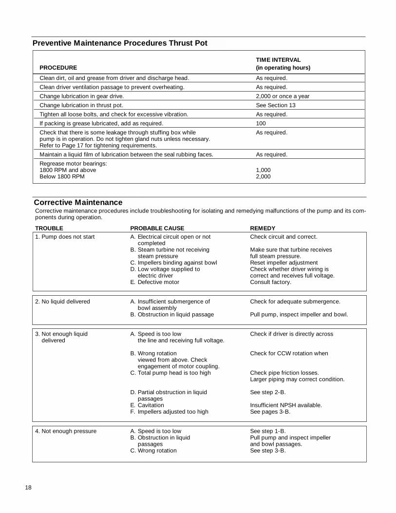
Corrective MaintenanceCorrective maintenance procedures include troubleshooting for isolating and remedying malfunctions of the pump and its com-ponents during operation.
TROUBLE PROBABLE CAUSE REMEDY1. Pump does not start A. Electrical circuit open or not Check circuit and correct.
completedB. Steam turbine not receiving Make sure that turbine receives
steam pressure full steam pressure.C. Impellers binding against bowl Reset impeller adjustmentD. Low voltage supplied to Check whether driver wiring is
electric driver correct and receives full voltage.E. Defective motor Consult factory.
2. No liquid delivered A. Insufficient submergence of Check for adequate submergence.bowl assembly
B. Obstruction in liquid passage Pull pump, inspect impeller and bowl.
3. Not enough liquid A. Speed is too low Check if driver is directly acrossdelivered the line and receiving full voltage.
B. Wrong rotation Check for CCW rotation whenviewed from above. Checkengagement of motor coupling.
C. Total pump head is too high Check pipe friction losses.Larger piping may correct condition.
D. Partial obstruction in liquid See step 2-B.passages
E. Cavitation Insufficient NPSH available.F. Impellers adjusted too high See pages 3-B.
4. Not enough pressure A. Speed is too low See step 1-B.B. Obstruction in liquid Pull pump and inspect impeller
passages and bowl passages.C. Wrong rotation See step 3-B.
TIME INTERVALPROCEDURE (in operating hours)
Clean dirt, oil and grease from driver and discharge head. As required.
Clean driver ventilation passage to prevent overheating. As required.
Change lubrication in gear drive. 2,000 or once a year
Change lubrication in thrust pot. See Section 13
Tighten all loose bolts, and check for excessive vibration. As required.
If packing is grease lubricated, add as required. 100
Check that there is some leakage through stuffing box while As required.pump is in operation. Do not tighten gland nuts unless necessary.Refer to Page 17 for tightening requirements.
Maintain a liquid film of lubrication between the seal rubbing faces. As required.
Regrease motor bearings:1800 RPM and above 1,000Below 1800 RPM 2,000
Preventive Maintenance Procedures Thrust Pot
19
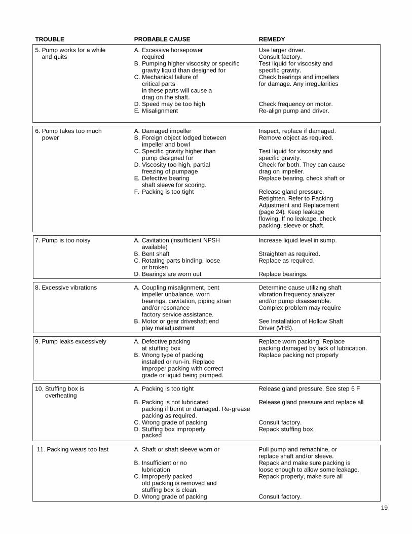
7. Pump is too noisy A. Cavitation (insufficient NPSH Increase liquid level in sump.available)
B. Bent shaft Straighten as required.C. Rotating parts binding, loose Replace as required.
or brokenD. Bearings are worn out Replace bearings.
8. Excessive vibrations A. Coupling misalignment, bent Determine cause utilizing shaftimpeller unbalance, worn vibration frequency analyzerbearings, cavitation, piping strain and/or pump disassemble.and/or resonance Complex problem may requirefactory service assistance.
B. Motor or gear driveshaft end See Installation of Hollow Shaftplay maladjustment Driver (VHS).
9. Pump leaks excessively A. Defective packing Replace worn packing. Replaceat stuffing box packing damaged by lack of lubrication.
B. Wrong type of packing Replace packing not properlyinstalled or run-in. Replaceimproper packing with correctgrade or liquid being pumped.
10. Stuffing box is A. Packing is too tight Release gland pressure. See step 6 Foverheating
B. Packing is not lubricated Release gland pressure and replace allpacking if burnt or damaged. Re-greasepacking as required.
C. Wrong grade of packing Consult factory.D. Stuffing box improperly Repack stuffing box.
packed
11. Packing wears too fast A. Shaft or shaft sleeve worn or Pull pump and remachine, or replace shaft and/or sleeve.
B. Insufficient or no Repack and make sure packing is lubrication loose enough to allow some leakage.
C. Improperly packed Repack properly, make sure allold packing is removed andstuffing box is clean.
D. Wrong grade of packing Consult factory.
TROUBLE PROBABLE CAUSE REMEDY
5. Pump works for a while A. Excessive horsepower Use larger driver.and quits required Consult factory.
B. Pumping higher viscosity or specific Test liquid for viscosity andgravity liquid than designed for specific gravity.
C. Mechanical failure of Check bearings and impellerscritical parts for damage. Any irregularitiesin these parts will cause adrag on the shaft.
D. Speed may be too high Check frequency on motor.E. Misalignment Re-align pump and driver.
6. Pump takes too much A. Damaged impeller Inspect, replace if damaged.power B. Foreign object lodged between Remove object as required.
impeller and bowlC. Specific gravity higher than Test liquid for viscosity and
pump designed for specific gravity.D. Viscosity too high, partial Check for both. They can cause
freezing of pumpage drag on impeller.E. Defective bearing Replace bearing, check shaft or
shaft sleeve for scoring.F. Packing is too tight Release gland pressure.
Retighten. Refer to PackingAdjustment and Replacement(page 24). Keep leakageflowing. If no leakage, checkpacking, sleeve or shaft.
20
Section 6 - Disassembly & ReassemblyDisassembly
NOTE: Pump components should be match-marked prior todisassembly to ensure they are reassembled in the correctlocation.
HEAD AND COLUMN
1. On pumps which are driven through a gear drive, removethe driveshaft between the gear and the prime mover.
2. On pumps, which are electric motor driven, remove theelectrical connections at the conduit box and tag the elec-trical leads, so they can be reassembled the same waythey were disassembled.
3. Uncouple driver (or gear box) from pump shaft and mounting flanges and lift off by the lifting lugs or eyeboltsas furnished.
4. Disconnect discharge head from the discharge piping.Remove all hold down bolts and integral piping. Removecoupling, packing box and proceed with disassemblydown to the bowls by reversing the procedures describedin detail for assembling the unit.
BOWL ASSEMBLY
The bowl assembly is composed of a suction bell, intermedi-ate bowl(s), discharge bowl, impellers and securing hardware,bearings, and pump shaft.
Turbine bowl impellers are secured to the shaft by either ataper collet or a key and split thrust ring. Follow only thoseprocedures that apply to the particular construction supplied.
NOTE: Match mark bowl assembly in sequence of disas-sembly to aid in the reassembly procedure.
TAPER LOCK CONSTRUCTION BOWL DISASSMBLY
1. Remove capscrews that secure discharge bowl (669) tointermediate bowl (670).
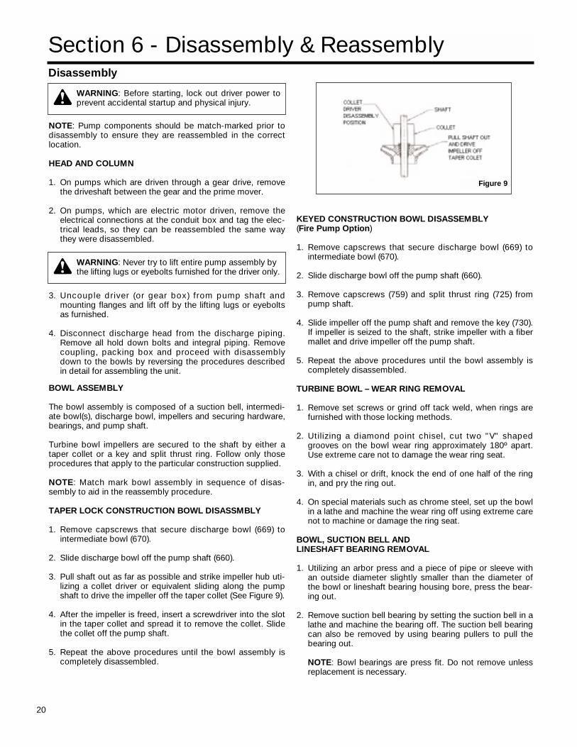
2. Slide discharge bowl off the pump shaft (660).
3. Pull shaft out as far as possible and strike impeller hub uti-lizing a collet driver or equivalent sliding along the pumpshaft to drive the impeller off the taper collet (See Figure 9).
4. After the impeller is freed, insert a screwdriver into the slotin the taper collet and spread it to remove the collet. Slidethe collet off the pump shaft.
5. Repeat the above procedures until the bowl assembly iscompletely disassembled.
KEYED CONSTRUCTION BOWL DISASSEMBLY(Fire Pump Option)
1. Remove capscrews that secure discharge bowl (669) tointermediate bowl (670).
2. Slide discharge bowl off the pump shaft (660).
3. Remove capscrews (759) and split thrust ring (725) frompump shaft.
4. Slide impeller off the pump shaft and remove the key (730).If impeller is seized to the shaft, strike impeller with a fibermallet and drive impeller off the pump shaft.
5. Repeat the above procedures until the bowl assembly iscompletely disassembled.
TURBINE BOWL – WEAR RING REMOVAL
1. Remove set screws or grind off tack weld, when rings arefurnished with those locking methods.
2. Utilizing a diamond point chisel, cut two "V" shapedgrooves on the bowl wear ring approximately 180º apart.Use extreme care not to damage the wear ring seat.
3. With a chisel or drift, knock the end of one half of the ringin, and pry the ring out.
4. On special materials such as chrome steel, set up the bowlin a lathe and machine the wear ring off using extreme carenot to machine or damage the ring seat.
BOWL, SUCTION BELL ANDLINESHAFT BEARING REMOVAL
1. Utilizing an arbor press and a piece of pipe or sleeve withan outside diameter slightly smaller than the diameter ofthe bowl or lineshaft bearing housing bore, press the bear-ing out.
2. Remove suction bell bearing by setting the suction bell in alathe and machine the bearing off. The suction bell bearingcan also be removed by using bearing pullers to pull thebearing out.
NOTE: Bowl bearings are press fit. Do not remove unlessreplacement is necessary.
WARNING: Never try to lift entire pump assembly by the lifting lugs or eyebolts furnished for the driver only.
WARNING: Before starting, lock out driver power toprevent accidental startup and physical injury.
Figure 9
21
Inspection & Replacement
1. Clean all pump parts thoroughly with a suitable cleaner.
2. Check bearing retainers for deformation and wear.
3. Check shafts for straightness and excessive wear on bear-ing surfaces. Check deflection of shafts, average totalrunout shall not exceed 0.005" (0.13mm) T.I.R. for every 10feet (3m) of shaft length.
4. Visually check impellers and bowls for cracks and pitting.Check all bowl bearings for excessive wear and corrosion.
5. Replace all badly worn or damaged parts with new parts.In addition, replace all gaskets and packing as required.
TURBINE BOWL WEAR RING INSTALLATION
1. Place chamfered face of the bowl or impeller wear ringtowards the ring seat and press the ring into the seat. Usean arbor press or equal, making sure the ring is flush withthe edge or the wear ring seat.
BOWL, SUCTION BELL AND LINESHAFT BEARING INSTALLATION
1. Press bearing (653) into retainer (652) using an arbor pressor equal.
2. Press bearing (690) into suction bell (689) using an arborpress or equal.
3. Press bearings (672) into intermediate bowl (670) andbeaing (664) into discharge bowl (669). Place the bowl withthe flange downward and press bearing through cham-fered side of bowl hub until the bearing is flush with thehub using an arbor press or equal.
TAPER COLLET CONSTRUCTION BOWL ASSEMBLY
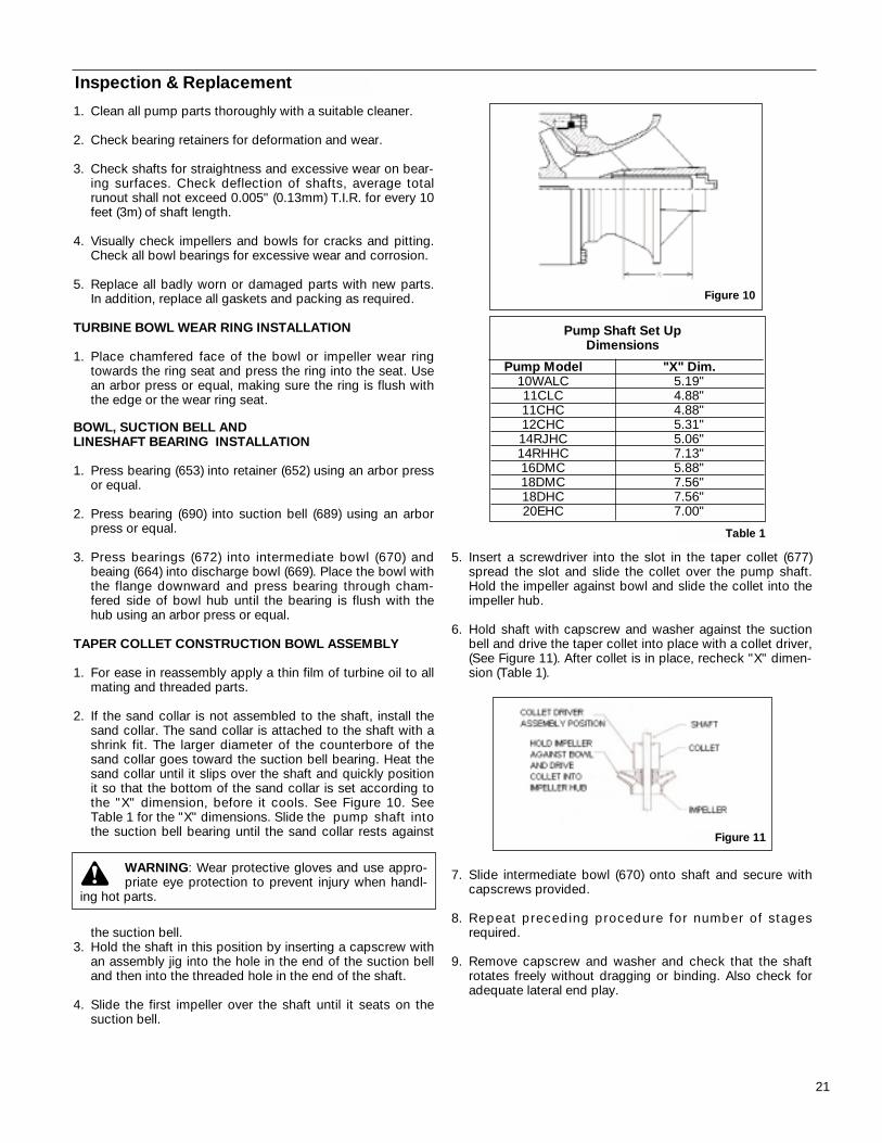
1. For ease in reassembly apply a thin film of turbine oil to allmating and threaded parts.
2. If the sand collar is not assembled to the shaft, install thesand collar. The sand collar is attached to the shaft with ashrink fit. The larger diameter of the counterbore of thesand collar goes toward the suction bell bearing. Heat thesand collar until it slips over the shaft and quickly positionit so that the bottom of the sand collar is set according tothe "X" dimension, before it cools. See Figure 10. SeeTable 1 for the "X" dimensions. Slide the pump shaft intothe suction bell bearing until the sand collar rests against
the suction bell.3. Hold the shaft in this position by inserting a capscrew with
an assembly jig into the hole in the end of the suction belland then into the threaded hole in the end of the shaft.
4. Slide the first impeller over the shaft until it seats on thesuction bell.
5. Insert a screwdriver into the slot in the taper collet (677)spread the slot and slide the collet over the pump shaft.Hold the impeller against bowl and slide the collet into theimpeller hub.
6. Hold shaft with capscrew and washer against the suctionbell and drive the taper collet into place with a collet driver,(See Figure 11). After collet is in place, recheck "X" dimen-sion (Table 1).
7. Slide intermediate bowl (670) onto shaft and secure withcapscrews provided.
8. Repeat preceding procedure for number of stagesrequired.
9. Remove capscrew and washer and check that the shaftrotates freely without dragging or binding. Also check foradequate lateral end play.
Figure 11
Figure 10
Pump Shaft Set Up Dimensions
Pump Model "X" Dim.10WALC 5.19"11CLC 4.88"11CHC 4.88"12CHC 5.31"14RJHC 5.06"14RHHC 7.13"16DMC 5.88"18DMC 7.56"18DHC 7.56"20EHC 7.00"
Table 1
WARNING: Wear protective gloves and use appro-priate eye protection to prevent injury when handl-
ing hot parts.
22
Section 7 - Repair Parts
ORDERING PARTS
When ordering spare or replacement parts. The pump serialnumber and size and type of pump must be given. This can befound on the nameplate furnished with the unit. Give the com-plete name and reference number of each part as indi-cated on the applicable sectional drawings, Figure 12 orFigure 13, and the quantity required.
STOCKING SPARE PARTS
Spare parts to be kept in inventory will vary according to ser-vice, field maintenance, allowable down time and number ofunits. A minimum inventory of one complete set of bearingsand one spare of each moving part is suggested.
RETURNING PARTS
A completed Return Material Authorization (RMA) form mustaccompany all materials returned to the factory. The RMAforms can be obtained direct form the factory or through yourA-C Fire Pump Systems representative. The RMA form mustbe filled in completely and forwarded as directed thereon.Parts being returned under warranty claim must have a com-plete written report submitted with the RMA form.
CAUTION: Returned material must be carefully pack-aged to prevent transit damage – the factory cannot
assume any responsibility for parts damaged in transit.
KEYED CONSTRUCTION BOWL ASSEMBLY
1. Install key (730E) into pump shaft keyway, slide impeller(673) over shaft and locate it on the key.
2. Install split thrust ring (725) on pump shaft groove andsecure to impeller with capscrews (759E).
3. Slide intermediate bowl (670) over pump shaft and secureto suction bell (689) with capscrews (759E).
4. Repeat preceding procedures for the number of stagesrequired.
FINAL ASSEMBLY
After assembly of bowl assembly, reassemble pump asdescribed in Section 3, Installation. Refer to Section 4,Operation for startup and adjusting procedures.
23
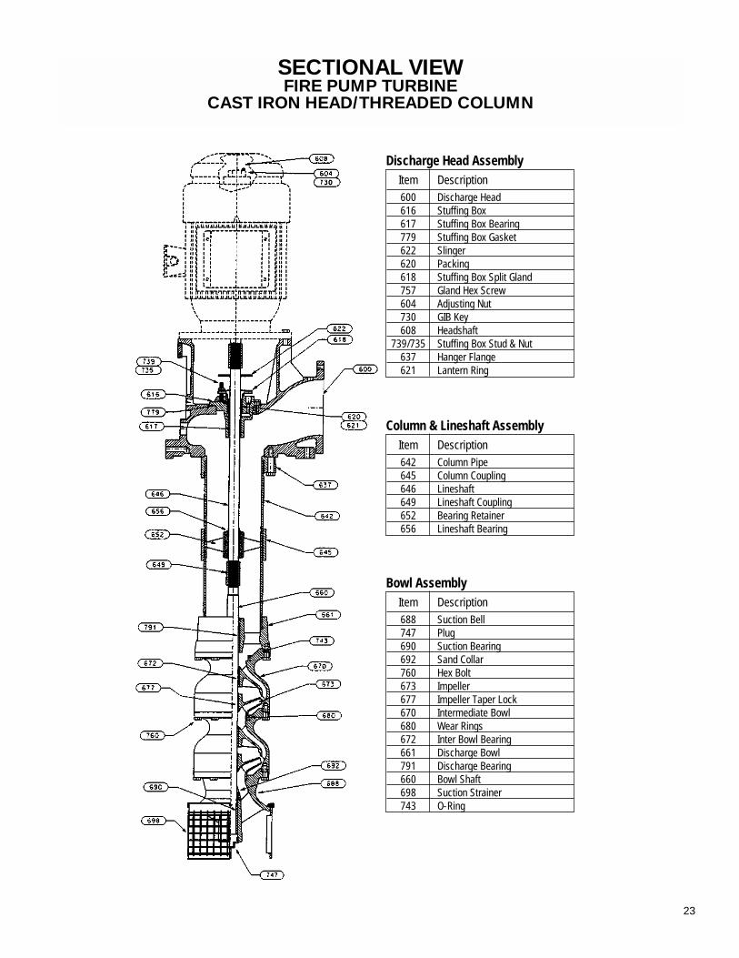
Item Description600 Discharge Head616 Stuffing Box617 Stuffing Box Bearing779 Stuffing Box Gasket622 Slinger620 Packing618 Stuffing Box Split Gland757 Gland Hex Screw604 Adjusting Nut730 GIB Key608 Headshaft
739/735 Stuffing Box Stud & Nut637 Hanger Flange621 Lantern Ring
Discharge Head Assembly
Item Description688 Suction Bell747 Plug690 Suction Bearing692 Sand Collar760 Hex Bolt673 Impeller677 Impeller Taper Lock670 Intermediate Bowl680 Wear Rings672 Inter Bowl Bearing661 Discharge Bowl791 Discharge Bearing660 Bowl Shaft698 Suction Strainer743 O-Ring
Bowl Assembly
Item Description642 Column Pipe645 Column Coupling646 Lineshaft649 Lineshaft Coupling652 Bearing Retainer656 Lineshaft Bearing
Column & Lineshaft Assembly
SECTIONAL VIEWFIRE PUMP TURBINE
CAST IRON HEAD/THREADED COLUMN
24
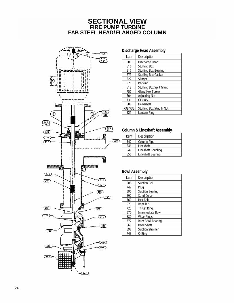
SECTIONAL VIEWFIRE PUMP TURBINE
FAB STEEL HEAD/FLANGED COLUMN
Item Description600 Discharge Head616 Stuffing Box617 Stuffing Box Bearing779 Stuffing Box Gasket622 Slinger620 Packing618 Stuffing Box Split Gland757 Gland Hex Screw604 Adjusting Nut730 GIB Key608 Headshaft
739/735 Stuffing Box Stud & Nut621 Lantern Ring
Discharge Head Assembly
Item Description688 Suction Bell747 Plug690 Suction Bearing692 Sand Collar760 Hex Bolt673 Impeller725 Thrust Ring670 Intermediate Bowl680 Wear Rings672 Inter Bowl Bearing660 Bowl Shaft698 Suction Strainer743 O-Ring
Bowl Assembly
Item Description642 Column Pipe646 Lineshaft649 Lineshaft Coupling656 Lineshaft Bearing
Column & Lineshaft Assembly
25
Appendix IAPPENDIX I
FIELD SERVICE
INSTALLATION AND STARTUP CHECKLIST
Customer: ____________________________ A-C Fire Pump Serial No.: ___________________
Pump Model: _______________ Pump Size: _______________ Stages: __________________
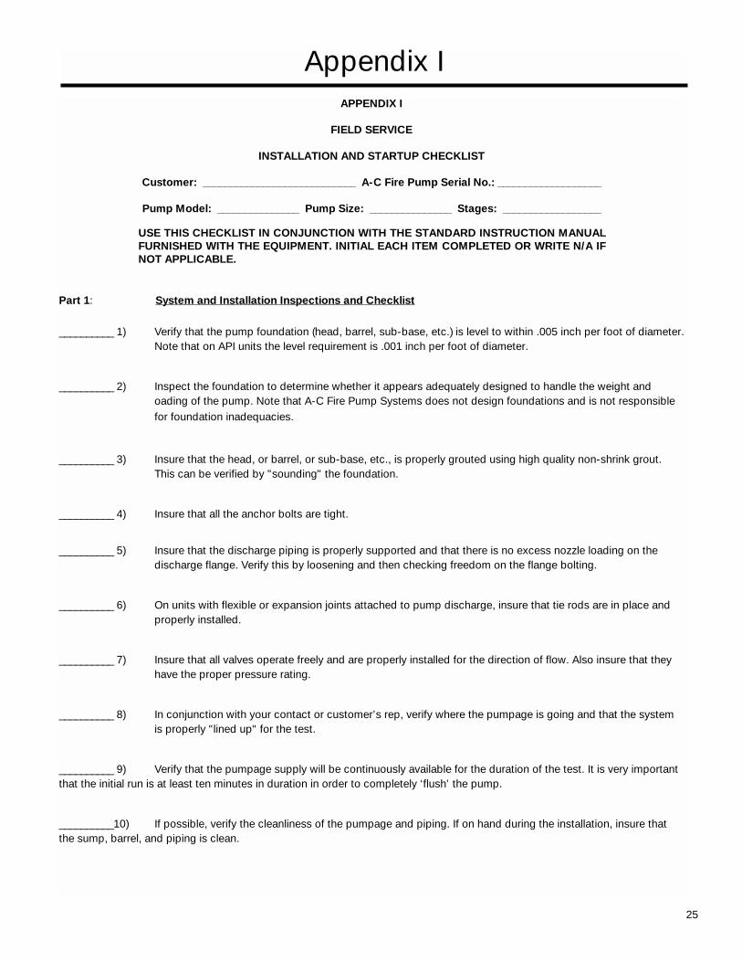
Part 1: System and Installation Inspections and Checklist
__________ 1) Verify that the pump foundation (head, barrel, sub-base, etc.) is level to within .005 inch per foot of diameter.Note that on API units the level requirement is .001 inch per foot of diameter.
__________ 2) Inspect the foundation to determine whether it appears adequately designed to handle the weight and oading of the pump. Note that A-C Fire Pump Systems does not design foundations and is not responsible for foundation inadequacies.
__________ 3) Insure that the head, or barrel, or sub-base, etc., is properly grouted using high quality non-shrink grout. This can be verified by "sounding" the foundation.
__________ 4) Insure that all the anchor bolts are tight.
__________ 5) Insure that the discharge piping is properly supported and that there is no excess nozzle loading on thedischarge flange. Verify this by loosening and then checking freedom on the flange bolting.
__________ 6) On units with flexible or expansion joints attached to pump discharge, insure that tie rods are in place and properly installed.
__________ 7) Insure that all valves operate freely and are properly installed for the direction of flow. Also insure that they have the proper pressure rating.
__________ 8) In conjunction with your contact or customer’s rep, verify where the pumpage is going and that the system is properly "lined up" for the test.
__________ 9) Verify that the pumpage supply will be continuously available for the duration of the test. It is very important that the initial run is at least ten minutes in duration in order to completely ‘flush’ the pump.
__________10) If possible, verify the cleanliness of the pumpage and piping. If on hand during the installation, insure that the sump, barrel, and piping is clean.
USE THIS CHECKLIST IN CONJUNCTION WITH THE STANDARD INSTRUCTION MANUALFURNISHED WITH THE EQUIPMENT. INITIAL EACH ITEM COMPLETED OR WRITE N/A IFNOT APPLICABLE.
26
APPENDIX I
FIELD SERVICE
INSTALLATION AND STARTUP CHECKLIST
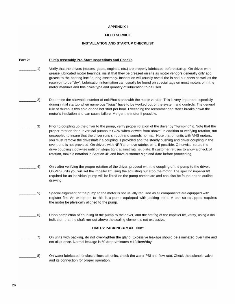
Part 2: Pump Assembly Pre-Start Inspections and Checks
__________ 1) Verify that the drivers (motors, gears, engines, etc.) are properly lubricated before startup. On drives with grease lubricated motor bearings, insist that they be greased on site as motor vendors generally only add grease to the bearing itself during assembly. Inspection will usually reveal the in and out ports as well as thereservoir to be "dry". Lubrication information can usually be found on special tags on most motors or in the motor manuals and this gives type and quantity of lubrication to be used.
__________ 2) Determine the allowable number of cold/hot starts with the motor vendor. This is very important especially during initial startup when numerous "bugs" have to be worked out of the system and controls. The general rule of thumb is two cold or one hot start per hour. Exceeding the recommended starts breaks down the motor’s insulation and can cause failure. Merger the motor if possible.
__________ 3) Prior to coupling up the driver to the pump, verify proper rotation of the driver by "bumping" it. Note that the proper rotation for our vertical pumps is CCW when viewed from above. In addition to verifying rotation, run uncoupled to insure that the driver runs smooth and sounds normal. Note that on units with VHS motors, you must remove the driveshaft if a coupling is provided and the steady bushing and driver coupling in the event one is not provided. On drivers with NRR’s remove ratchet pins, if possible. Otherwise, rotate the drive coupling clockwise until pin stops tight against ratchet plate. If customer refuses to allow a check of rotation, make a notation in Section 4B and have customer sign and date before proceeding.
__________ 4) Only after verifying the proper rotation of the driver, proceed with the coupling of the pump to the driver. On VHS units you will set the impeller lift using the adjusting nut atop the motor. The specific impeller lift required for an individual pump will be listed on the pump nameplate and can also be found on the outline drawing.
__________ 5) Special alignment of the pump to the motor is not usually required as all components are equipped withregister fits. An exception to this is a pump equipped with jacking bolts. A unit so equipped requires the motor be physically aligned to the pump.
__________ 6) Upon completion of coupling of the pump to the driver, and the setting of the impeller lift, verify, using a dial indicator, that the shaft run-out above the sealing element is not excessive.
LIMITS: PACKING = MAX. .008"
__________ 7) On units with packing, do not over-tighten the gland. Excessive leakage should be eliminated over time andnot all at once. Normal leakage is 60 drops/minutes = 13 liters/day.
__________ 8) On water lubricated, enclosed lineshaft units, check the water PSI and flow rate. Check the solenoid valve and its connection for proper operation.
27
APPENDIX I
FIELD SERVICE
INSTALLATION AND STARTUP CHECKLIST
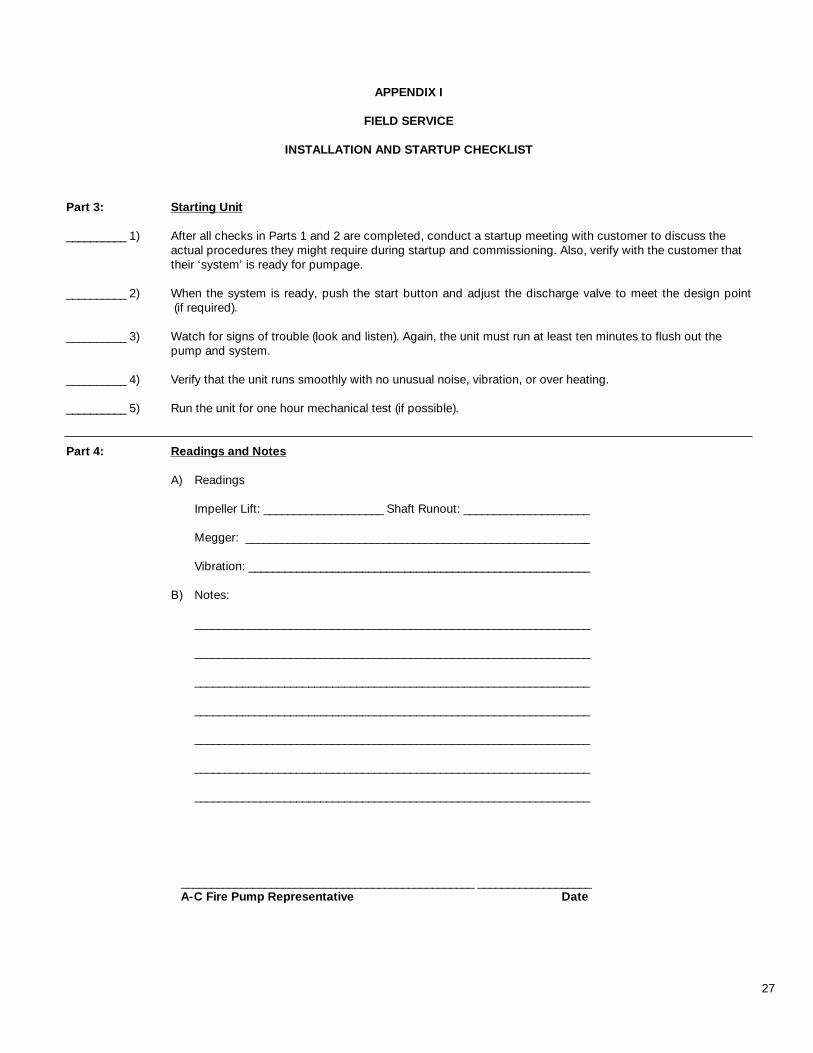
Part 3: Starting Unit
__________ 1) After all checks in Parts 1 and 2 are completed, conduct a startup meeting with customer to discuss the actual procedures they might require during startup and commissioning. Also, verify with the customer that their ‘system’ is ready for pumpage.
__________ 2) When the system is ready, push the start button and adjust the discharge valve to meet the design point(if required).
__________ 3) Watch for signs of trouble (look and listen). Again, the unit must run at least ten minutes to flush out the pump and system.
__________ 4) Verify that the unit runs smoothly with no unusual noise, vibration, or over heating.
__________ 5) Run the unit for one hour mechanical test (if possible).
Part 4: Readings and Notes
A) Readings
Impeller Lift: ____________________ Shaft Runout: _____________________
Megger: __________________________________________________________
Vibration: _________________________________________________________
B) Notes:
__________________________________________________________________
__________________________________________________________________
__________________________________________________________________
__________________________________________________________________
__________________________________________________________________
__________________________________________________________________
__________________________________________________________________
_________________________________________________ ___________________A-C Fire Pump Representative Date

PRINTED IN U.S.A. 10-02
A-C Fire Pump Systems8200 N. Austin AvenueMorton Grove, IL 60053Phone: (847) 966-3700Fax: (847) 966-1914www.acfirepump.com
In CanadaFluid Products Canada55 Royal RoadGuelph, Ontario, N1H 1T1, CanadaPhone: (519) 821-1900Fax: (519) 821-2569
DIN ISO 9001
TUVCERT
ISO 9001Certified
A-C Fire Pump