
The Large Hadron Collider - Philosophical Transactions of...
28
Phil. Trans. R. Soc. A (2012) 370, 831–858 doi:10.1098/rsta.2011.0453 R EVIEW The Large Hadron Collider B Y L YNDON E VANS 1,2, * 1 CERN, CH-1211 Geneva 23, Switzerland 2 Imperial College London, London SW7 2HZ, UK The construction of the Large Hadron Collider (LHC) has been a massive endeavour spanning almost 30 years from conception to commissioning. Building the machine with the highest possible energy (7 TeV) in the existing large electron–positron (LEP) collider tunnel of 27 km circumference and with a tunnel diameter of only 3.8 m has required considerable innovation. The first was the development of a two-in-one magnet, where the two rings are integrated into a single magnetic structure. This compact two-in-one structure was essential for the LHC owing to the limited space available in the existing LEP collider tunnel and the cost. The second was a bold move to the use of superfluid helium cooling on a massive scale, which was imposed by the need to achieve a high (8.3 T) magnetic field using an affordable Nb-Ti superconductor. Keywords: Large Hadron Collider; collider; accelerator 1. Introduction In this paper, no attempt is made to give a comprehensive review of the machine design. This can be found in the Large Hadron Collider (LHC) Design Report [1], which gives a detailed description of the machine as it was built and comprehensive references. A more popular description of the LHC and its detectors can be found in Evans [2]. Instead, this is a more personal account of the project from approval to commissioning, describing some of the main technologies and some of the challenges encountered during its construction and commissioning. 2. Approval of the Large Hadron Collider The LHC had a difficult birth. Although the idea of a large proton–proton collider at CERN had been around since at least 1977, the approval of the superconducting super collider (SSC) in the USA in 1987 [3] put the whole project into doubt. The SSC, with a centre-of-mass energy of 40TeV, was almost three times more powerful than what could ever be built at CERN (the European *[email protected] One contribution of 15 to a Discussion Meeting Issue ‘Physics at the high-energy frontier: the Large Hadron Collider project’. This journal is © 2012 The Royal Society 831 on May 9, 2018 http://rsta.royalsocietypublishing.org/ Downloaded from
Transcript of The Large Hadron Collider - Philosophical Transactions of...

Phil. Trans. R. Soc. A (2012) 370, 831–858doi:10.1098/rsta.2011.0453
REVIEW
The Large Hadron ColliderBY LYNDON EVANS1,2,*
1CERN, CH-1211 Geneva 23, Switzerland2Imperial College London, London SW7 2HZ, UK
The construction of the Large Hadron Collider (LHC) has been a massive endeavourspanning almost 30 years from conception to commissioning. Building the machine withthe highest possible energy (7 TeV) in the existing large electron–positron (LEP) collidertunnel of 27 km circumference and with a tunnel diameter of only 3.8 m has requiredconsiderable innovation. The first was the development of a two-in-one magnet, wherethe two rings are integrated into a single magnetic structure. This compact two-in-onestructure was essential for the LHC owing to the limited space available in the existingLEP collider tunnel and the cost. The second was a bold move to the use of superfluidhelium cooling on a massive scale, which was imposed by the need to achieve a high(8.3 T) magnetic field using an affordable Nb-Ti superconductor.
Keywords: Large Hadron Collider; collider; accelerator
1. Introduction
In this paper, no attempt is made to give a comprehensive review of themachine design. This can be found in the Large Hadron Collider (LHC) DesignReport [1], which gives a detailed description of the machine as it was builtand comprehensive references. A more popular description of the LHC and itsdetectors can be found in Evans [2]. Instead, this is a more personal accountof the project from approval to commissioning, describing some of the maintechnologies and some of the challenges encountered during its construction andcommissioning.
2. Approval of the Large Hadron Collider
The LHC had a difficult birth. Although the idea of a large proton–protoncollider at CERN had been around since at least 1977, the approval of thesuperconducting super collider (SSC) in the USA in 1987 [3] put the whole projectinto doubt. The SSC, with a centre-of-mass energy of 40 TeV, was almost threetimes more powerful than what could ever be built at CERN (the European*[email protected]
One contribution of 15 to a Discussion Meeting Issue ‘Physics at the high-energy frontier: the LargeHadron Collider project’.
This journal is © 2012 The Royal Society831
on May 9, 2018http://rsta.royalsocietypublishing.org/Downloaded from

832 L. Evans
Laboratory for Particle Physics). It was only the resilience and conviction ofCarlo Rubbia, who shared the 1984 Nobel Prize in Physics for the discovery of theW and Z bosons, that kept the project alive. Rubbia, who became the DirectorGeneral of CERN in 1989, argued that, in spite of its disadvantage in energy,the LHC could be competitive with the SSC by having a luminosity an order ofmagnitude higher than could be achieved with the SSC, and at a fraction of thecost. He also argued that the LHC would be more versatile. As well as collidingprotons, it would be able to accelerate heavy ions to world-beating energies atlittle extra cost.
The SSC was eventually cancelled in 1993 [4]. This made the case for thebuilding of the LHC even stronger, but the financial climate in Europe at the timewas not conducive to the approval of a large project. CERN’s largest contributor,Germany, was struggling with the cost of reunification and many other countrieswere trying to get to grips with the problem of meeting the Maastricht criteriafor the introduction of the single European currency.
During the course of 1993, an extensive review was made in order to reducethe cost as much as possible, although a detailed cost estimate was particularlydifficult to make since much of the research and development on the most criticalcomponents was still to be done. In December 1993, a plan [5] was presentedto the CERN Council to build the machine over a 10 year period by reducingthe other experimental programme of CERN to the absolute minimum, with theexception of the full exploitation of the large electron–positron (LEP) collider,which was the flagship machine of the decade.
Although the plan was generally well received, it became clear that two of thelargest contributors, Germany and the UK, were very unlikely to agree with thebudget increase required. They also managed to get Council voting procedureschanged from a simple majority to a double majority, where much more weightwas given to the large contributors so that they could keep control.
On the positive side, after the demise of the SSC, a US panel on the futureof particle physics [6] recommended that ‘the government should declare itsintentions to join other nations in constructing the LHC’. Positive signals werealso being received from India, Japan and Russia.
In June 1994, the proposal to build the LHC was made once more. Counciladopted a very unusual procedure in which the vote on the Resolution was openedso that countries in a position to vote could do so, but neither the vote northe Council Session was closed [7]. Seventeen member states voted to approvethe project. However, because of the newly adopted double voting procedure,approval was blocked by Germany and the UK, which demanded substantialadditional contributions from the two host states, France and Switzerland,claiming that they obtained disproportionate returns from the CERN budget.They also requested that financial planning should proceed under the assumptionof 2 per cent annual inflation, with a budget compensation of 1 per cent,essentially resulting in a 1 per cent annual reduction in real terms.
In order to deal with this new constraint, CERN was forced to propose a‘missing magnet’ machine in which only two-thirds of the dipole magnets neededto guide the beams on their quasi-circular orbits would be installed in the firststage, allowing the machine to run with reduced energy for a number of years,eventually upgrading to full energy. This would have been a very inefficient wayof building the machine, costing more in the long run but saving some 300 million
Phil. Trans. R. Soc. A (2012)
on May 9, 2018http://rsta.royalsocietypublishing.org/Downloaded from

Review. The Large Hadron Collider 833
Swiss francs in the first phase. This proposal was put to Council in December1994. After a round of intense discussions between France, Switzerland, Germanyand the UK, the deadlock concerning extra host-state contributions was brokenwhen France and Switzerland agreed to make extra voluntary contributions inthe form of a 2 per cent annual inflation adjustment, compared with the 1 percent adjustment from the other member states. In the continuation of the 100thSession of Council, still open from the June meeting, the project was finallyapproved [8] for two-stage construction, to be reviewed in 1997 after the sizeof the contribution offered by non-member states interested in joining the LHCprogramme would be known. The tough negotiations with France and Switzerlandwere couched in diplomatic language in the Considerata of the Council Resolution‘The CERN Council. . .Notes with gratitude, the commitments of Franceand Switzerland to make voluntary contributions to help and accelerate theLHC project’.
There followed an intense round of negotiations with potential contributors.The first country to declare a financial contribution was Japan, which becamean observer to the CERN Council in June 1995. The declaration from Japan wasquickly followed by that from India and Russia in March 1996 and by that fromCanada in December 1996.
A final sting in the tail came in June 1996 from Germany, which unilaterallyannounced that, in order to ease the burden of reunification, it intended toreduce its CERN subscription by between 8 and 9 per cent. Confining the cut toGermany proved impossible. The UK was the first to demand a similar reductionin its contribution in spite of a letter from the UK Science Minister during theprevious round of negotiations stating that the conditions are ‘reasonable, fairand sustainable’. The only way out was to allow CERN to take out loans, withrepayment to continue after the completion of LHC construction.
In the December 1996 Council, Germany declared that ‘a greater degree ofrisk would inevitably have to accompany the LHC’. The project was approvedfor single-stage construction with the deficit financed by loans. It was also agreedthat the final cost of the project was to be reviewed at the half-way stage witha view to adjusting the completion date. With all contingency removed, it wasinevitable that a financial crisis would occur at some time, and this was indeed thecase when the cost estimate was revised upwards by 18 per cent in 2001. Althoughthis was an enviable achievement for a project of such technological complexityand with a cost estimate from 1993 before a single prototype had been made, itcertainly created big waves in Council. CERN was obliged to increase the level ofborrowing and extend the construction period (which was necessary anyway ontechnical grounds for both the machine and detectors).
In the meantime, following the recommendation of the US panel, and inpreparation for a substantial contribution, the US Department of Energy,responsible for particle physics research, carried out an independent review ofthe project [9]. It found that ‘the accelerator-project cost estimate of 2.3 billionin 1995 Swiss francs, or about $2 billion US, to be adequate and reasonable’.Moreover, it found that ‘Most important of all, the committee found that theproject has experienced and technically knowledgeable management in place andfunctioning well. The strong management team, together with the CERN historyof successful projects, gives the committee confidence in the successful completionof the LHC project.’ In December 1997, at a ceremony in Washington, DC, in
Phil. Trans. R. Soc. A (2012)
on May 9, 2018http://rsta.royalsocietypublishing.org/Downloaded from

834 L. Evans
the splendid Indian Treaty Room of the White House Annex, an agreement wassigned between the Secretary of Energy and the President of the CERN Council.More than 1300 American physicists are users of CERN today.
After a shaky start and a mid-term hiccup, the project has proceededreasonably smoothly to completion. The LHC is a fine example of Europeancollaboration and leadership in science.
3. A brief history of colliders
Colliding beam machines (storage rings), with two beams of particles circulatingin opposite directions and colliding at a point on the circumference whereparticle detectors could be placed, were the dream of accelerator builders inthe late 1950s, since the energy available for producing new particles scalesas the beam energy and not as its square root, as in fixed-target experiments.In the early 1960s, the first machines started to appear at Stanford in theUSA, Frascati in Italy and Novosibirsk in Russia. Instead of protons, thesemachines collided leptons (electrons or positrons). One great advantage inusing electrons and positrons is that, when bent on a circular orbit, theyemit light (synchrotron radiation). The dynamics is such that the emissionof this radiation has a natural damping effect on the transverse dimensions,concentrating the particles into a very intense beam, essential if there is tobe a reasonable probability of two particles colliding instead of the beams justpassing through each other without interacting. It is also desirable that thebeams can circulate for many hours while data are collected. During this time,the particles are subjected to perturbations due to imperfections in the guidefield or the electromagnetic field of the other beam that can cause them tobecome unstable. Synchrotron radiation also plays an important role in combatingthese external perturbations owing to its natural damping effect. However, theemission of synchrotron radiation makes the particles lose energy, which hasto be replaced by the acceleration system. Essentially, the beams have to bepermanently accelerated in order to keep them at constant energy. The energylost at each revolution increases dramatically (with the fourth power) as theenergy of the machine increases, eventually making it impossible for the accelera-ting system to replace it. In spite of its usefulness, synchrotron radiation naturallylimits the maximum achievable energy of the machine. The way around this is torevert to particles that emit much less radiation.
In the late 1960s, a very bold step was taken at CERN with the construction ofthe first proton storage rings, called the intersecting storage rings (ISRs), whichstarted operation in 1969. The advantage of protons is that they do not emitsynchrotron radiation of any consequence since the energy loss per revolutionvaries as the inverse fourth power of the mass of the particle, and protons are2000 times heavier than electrons. The disadvantage is that they have to operatewithout the benefit of the strong damping provided by synchrotron radiation.Indeed, many accelerator physicists doubted that proton storage rings wouldwork at all.
In the end, the ISR was a big success for the machine builders and an essentialstep on the road to the LHC. The machine eventually reached 31 GeV per beam,compared with the few giga-electronvolts available from the lepton beams at that
Phil. Trans. R. Soc. A (2012)
on May 9, 2018http://rsta.royalsocietypublishing.org/Downloaded from

Review. The Large Hadron Collider 835
10 000
1000
1995: top
LHC(CERN)
LEP 200
LEP 1(CERN)1989: 3 families
PETRA 1979: gluon(DESY)
1974: J/y1975: t
SPEAR(Stanford)
HERA1983: W,Z
Tevatron
Spps(CERN)
(Fermilab)
100co
nstit
uent
cen
tre-
of-m
ass
ener
gy (
GeV
)
10
1
_
1960 1970 1980 1990year of first physics
2000 2010 2020
Figure 1. The history of colliders. Circles indicate the lepton machines. Squares indicate the Hadronmachines, including three of the four constructed at CERN. The energy available in the quarks orgluons is about one-fifth of the beam energy. Circle labelled ‘HERA’, e–p collider; all other circles,e+ e− collider; square, Hadron collider. (Online version in colour.)
time. The accelerator physicists learned how to build proton storage rings thatovercame the lack of synchrotron radiation damping. Early ISR experiments werenot so successful because they mainly looked at forward angles, whereas the mostimportant physics was at large angles. This was an important lesson learnedfrom the ISR. The first modern four-pi detector was the mark 1 detector usedin SPEAR at Stanford, CA, in 1973. With this experience, the experimentalistslearned how to build detectors that worked in the difficult environment of aproton–proton collider.
Another step on the road to the LHC was taken during the long period of LEPcollider construction. During this time, Carlo Rubbia proposed that the superproton synchrotron (SPS), built in the 1970s as a ‘fixed target’ machine, couldbe turned into a hadron collider using the newly discovered technique proposedby Simon Van de Meer at CERN and first demonstrated experimentally byWolfgang Schnell in the ISR of accumulating and cooling antiprotons produced inCERN’s oldest machine, the CERN proton synchrotron (PS). Since protons andantiprotons have the same mass but opposite charge, they could be acceleratedin opposite directions in the single vacuum chamber of the SPS. Collisions at273 GeV per beam produced the first W and Z bosons, the mediators of the weaknuclear force responsible for radioactive decay in the two (then) massive detectorschristened UA (for underground areas) 1 and 2, purpose built for their detection.
The proton–antiproton collider (PPBAR) also provided the essential remaininginformation needed for the design of the LHC and its detectors. For the LHCmachine, it elucidated the main factors that would limit its performance, andthe two detectors UA1 and UA2 served as prototypes for the much larger LHC
Phil. Trans. R. Soc. A (2012)
on May 9, 2018http://rsta.royalsocietypublishing.org/Downloaded from

836 L. Evans
Figure 2. The Large Hadron Collider. (Online version in colour.)
detectors. Indeed, the nucleus of the teams designing the two large LHC detectors,ATLAS and CMS, comes from these earlier collaborations.
Across the Atlantic, a further bold step was taken with the construction of theworld’s first large superconducting synchrotron, the Tevatron at Fermilab. Thismachine showed that superconducting magnets, which inevitably have a poorerfield quality than conventional magnets, could operate in storage ring mode. TheTevatron took over the energy frontier from PPBAR in 1987 (figures 1–3).
4. The design of the Large Hadron Collider
The fact that the LHC was to be constructed at CERN, making the maximumpossible use of existing infrastructure to reduce cost, imposed a number of strongconstraints on the technical choices to be made.
Phil. Trans. R. Soc. A (2012)
on May 9, 2018http://rsta.royalsocietypublishing.org/Downloaded from

Review. The Large Hadron Collider 837
alignment target
Δ 9
14
Δ 1050Δ 570
main quadripole bus bars
heat exchanger pipe
superinsulation
superconducting coils
beam pipe
beam screen
auxiliary bus bars
shrinking cylinder/HE I-vessel
thermal shield (55–75 K)
non-magnetic collars
iron yoke (cold mass, 1.9 K)
dipole bus bars
support post
vacuum vessel
Figure 3. A cross section of the two-in-one LHC bending magnet. The two rings are concentratedinside a single vacuum vessel to save space (and money). (Online version in colour.)
The first of these was the 27 km circumference of the LEP collider tunnel.The maximum energy attainable in a circular machine depends on the productof the bending radius in the dipole magnets and the maximum field strengthattainable. Since the bending radius is constrained by the geometry of the tunnel,the magnetic field should be as high as possible. The field required to achieve thedesign energy of 7 TeV is 8.3 T, about 60 per cent higher than that achieved inprevious machines. This pushed the design of superconducting magnets and theirassociated cooling systems to a new frontier.
The next constraint was the small (3.8 m) tunnel diameter. It must not beforgotten that the LHC is (just like the ISR) not one but two machines. Asuperconducting magnet occupies a considerable amount of space. To keep itcold, it must be inserted into an evacuated vacuum vessel called a cryostat andwell insulated from external sources of heat. Owing to the small transverse sizeof the tunnel, it would have been impossible to fit two independent rings intothe space. Instead, a novel and elegant design with the two rings separated byonly 19 cm inside a common yoke and cryostat was developed. This was not onlynecessary on technical grounds, but also saved a considerable amount of money,some 20 per cent of the total project cost.
Finally, the re-use of the existing injector chain governed the maximum energyat which beams could be injected into the LHC.
Phil. Trans. R. Soc. A (2012)
on May 9, 2018http://rsta.royalsocietypublishing.org/Downloaded from

838 L. Evans
Table 1. Magnet types.
type number function
MB 1232 main dipolesMQ 392 arc quadrupolesMBX/MBR 16 separation and recombination dipolesMSCB 376 combined chromaticity and closed orbit correctorsMCS 2464 sextupole correctors for persistent currents at injectionMCDO 1232 octupole/decapole correctors for persistent currents at injectionMO 336 Landau dumping octupolesMQT/MQTL 248 tuning quadrupolesMCB 190 orbit correction dipolesMQM 86 dispersion suppressor and matching section quadrupolesMQY 24 enlarged-aperture quadrupoles in insertionsMQX 32 low-beta insertion quadrupoles
5. Magnets and cryogenics
At the heart of the LHC is the superconducting magnet system and associatedcryogenics. Table 1 lists all of the superconducting magnets in the machine.As well as the main dipoles and lattice quadrupoles, there are a large numberof other magnets for orbit and chromaticity correction, higher multi-poles tocontrol persistent currents and the special quadrupoles and dipoles in the low-beta insertions. There are also a number of strong octupoles to provide Landaudamping of coherent instabilities if needed.
The main dipoles need to operate at a much higher field (8.3 T for 7 TeV energy)than in any previous machine. This high field level can be obtained with two typesof superconductor. The ductile alloy niobium–titanium and the intermetalliccompound Nb3Sn are the only materials that can be used for such magnets today.Nb3Sn could reach the required performance in supercritical helium at 4.5 K, butit is mechanically brittle and costs at least five times as much as Nb-Ti. It is,therefore, excluded for large-scale series production. The only alternative is Nb-Ti, but it must be cooled to 1.9 K below the lambda point of helium to get therequired performance. This requires a very innovative cryogenic system.
The superconducting cable is made of strands of wire, about 1 mm in diameterand composed of one-third superconducting material and two-thirds copper.The Nb-Ti filaments are 6–7 mm in diameter and precisely positioned with 1 mmseparation in the copper matrix. They are produced by multiple co-extrusion ofNb-Ti ingots with copper rods and cans. The strands and multi-strand cable areshown in figure 4.
It is of interest to make the dipoles as long as possible to reduce thenumber of units and interconnects, and therefore the cost, and also to maximizethe filling factor, reducing the magnetic field required for a given energy.A number of practical factors, including the road transport of magnets andfacility of installation, put an upper limit on their length. The final magnetshave a magnetic length of 14.3 m with a physical length of 15 m. The regularlattice period is 106.9 m with six dipoles and two 3 m long quadrupoles per
Phil. Trans. R. Soc. A (2012)
on May 9, 2018http://rsta.royalsocietypublishing.org/Downloaded from

Review. The Large Hadron Collider 839
Figure 4. LHC superconductor and cable. (Online version in colour.)
106.90 m
MQ
MSC
BM
CD
O
MC
DO
MC
DO
MC
S
MC
S
MC
S
MC
S
MC
S
MC
SB
MO
, MO
T, M
OS
BPM
MQMBA MBA MBAMBB MBB MBB
Figure 5. The regular lattice. (Online version in colour.)
period. The ends of the dipoles contain the small octupole and decapolecorrectors to control unwanted multi-poles, especially in the ‘snapback’ regimeat the start of acceleration when persistent currents cause strong nonlinearities(figure 5).
In addition to these small correctors, each lattice period contains a sextupoleto correct the chromaticity as well as a dipole for orbit correction. Depending onits location in the machine, each period contains an additional corrector, eithera trim or skew quadrupole or a Landau octupole.
The mechanical forces in the dipole are very large, up to 300 tonnes m−1 pushingthe coils outwards at full power. These forces are contained by strong non-magnetic steel collars surrounded by an iron yoke and a stainless steel cylinder(figure 6).
Series production of dipoles and quadrupoles has been a monumental task.All superconducting cables and many mechanical components were supplied tothe cold mass assemblers (three for the dipoles and one for the quadrupoles) byCERN in order to ensure uniformity of production and also to allow control of thedistribution of contracts between countries. The cold masses were assembled into
Phil. Trans. R. Soc. A (2012)
on May 9, 2018http://rsta.royalsocietypublishing.org/Downloaded from

840 L. Evans
(a) (b)
Figure 6. (a) Cross-sectional model of the LHC dipole without the cryostat. (b) Magnetic couplingbetween the two apertures. (Online version in colour.)
their cryostats at CERN. All magnets were tested at 1.9 K before installation inthe tunnel. From start to finish, production, from cable to fully tested magnets,took about 6 years.
The total mass to be cooled to 1.9 K is 37 000 tonnes, requiring approximately80 tonnes of superfluid helium to be maintained at 1.9 K during the entireperiod of operation. The main reason for operating in superfluid is to extendthe operating range of the Nb-Ti superconductor. However, operating belowthe lambda point brings its own advantages and challenges. The rapid dropin the specific heat of the conductor at low temperature makes it imperativeto use the special properties of superfluid helium in the best possible way. Theinsulation between turns in the coil has been designed to be porous so that,with its low viscosity, the helium can permeate the windings where it buffersthermal transients owing to its high specific heat (2000 times that of the conductorper unit volume). The excellent thermal conductivity of the fluid (peaking at1.9 K and typically 1000 times that of oxygen-free high-conductivity (OFHC)copper) enables it to conduct heat without mass transport with no need for fluidcirculation or pumps.
The magnets operate in a static bath of superfluid at atmospheric pressureusing an unconventional cooling scheme. The bath is continuously cooled througha linear heat exchanger tube made out of cryogenic-grade copper and extendingthe full 107 m length of each cell (figure 7). The pressure inside the heat exchangeris 15 mbar. Helium expanded into the tube through a Joule–Thomson (JT) valveis cooled to 1.9 K. The static helium in the magnets is then cooled by latent heatof vaporization of the small quantity of superfluid inside the heat exchanger. Thisscheme has been shown to work beautifully, keeping the LHC temperature stablefor weeks on end.
At 7 TeV, even protons start to produce synchrotron radiation. The poweremitted is about 4 kW per beam, which is much too low to provide synchrotronradiation damping but is quite a nuisance since it must be absorbed on the coldsurface of the beam pipe. One watt at 1.9 K corresponds to a kilowatt at roomtemperature, which cannot be accepted by the refrigerators. Therefore, the beamvacuum chamber contains a liner cooled to 20 K in order to intercept the heatload with better thermodynamic efficiency.
Phil. Trans. R. Soc. A (2012)
on May 9, 2018http://rsta.royalsocietypublishing.org/Downloaded from

Review. The Large Hadron Collider 841
heat exchanger tubesaturated He II, flowing
magnet
helium vessel
pressurized He II, static
SC bus bar connection
Figure 7. Schematic of the LHC magnet cooling system. (Online version in colour.)
6. Machine layout
In parallel with the approval of the LHC machine, proposals for the experimentalprogramme were being examined by the LHC Experiments Committee (LHCC),whose job was to give advice to the CERN management and through it to Council.Unlike the machine, the detectors have considerable independence. Only 20 percent of their funding comes through CERN. The rest comes from collaboratinginstitutes all around the globe. However, it is the responsibility of CERN toprovide the infrastructure, including the caverns in which the experiments arehoused. Eventually, the LHCC proposed approval of two large general purposedetectors, ATLAS and CMS, as well as two smaller more specialized detectors,ALICE for heavy-ion physics and LHCb for the study of matter–antimatterasymmetry.
(a) Civil engineering
The first job was to decide where these detectors were to be located. The LHCring is segmented into eight identical arcs joined by eight 500 m long straightsections (LSSs), labelled from 1 to 8. Four of these LSSs (at points 2, 4, 6 and 8)already contained experimental caverns in which the four LEP detectors werelocated. These caverns were big enough to house the two smaller experiments.However, ATLAS and CMS required much bigger caverns, so excavation had tostart while the LEP collider was still running, the four even points thereforebeing excluded. Point 3 lies in a very inhospitable location deep under theJura Mountains and, for various reasons, point 7 could also be excluded. Thereremained point 1, conveniently situated opposite the CERN main campus anddiametrically opposite to point 5, the most remote of all. Needless to say, therewas considerable pressure from both ATLAS and CMS collaborations to get themore convenient point 1. In the end, geology prevailed. Sample borings showedthat point 1 was much better suited for the larger cavern required for ATLAS.CMS was allocated point 5. ALICE re-used the large electromagnet magnet ofone of the old LEP experiments at point 2 and LHCb was assigned the cavern atpoint 8 (figure 8).
Phil. Trans. R. Soc. A (2012)
on May 9, 2018http://rsta.royalsocietypublishing.org/Downloaded from

842 L. Evans
point 1: UX15 vault demolition of central pillar—20 September 2000—CERN ST-CE
Figure 8. Excavation of ATLAS. The cavern is the largest ever built in the type of rock encounteredin the Geneva basin. (Online version in colour.)
The excavation of the large caverns at points 1 and 5 posed different problems.At point 1, the cavern is the largest ever excavated in such ground conditions.The work also had to continue while the LEP machine was still operating. Atpoint 5, although the exploratory borings showed that there was a lot of groundwater to be traversed when sinking the shaft, the speed of water flow took us bysurprise. Extensive ground freezing was necessary to produce an ice wall aroundthe shaft excavation.
An additional complication at point 5 was that, during the preparation of theworksite, the foundations of an ancient Roman farm (fourth century AD) werediscovered. Work was immediately stopped so that the mandatory archaeologicalinvestigation could be made. Articles of jewellery and coins minted in London,Lyon and Ostia, the ancient harbour city 35 km southwest of Rome, were found.The coins minted in London were dated AD 309–312. One striking feature easilyseen from the air (figure 9) is the precise alignment of the villa with respect tothe boundaries of the present-day fields. This is evidence that the ‘cadastre’, orland registry of today, is derived from the time of the Roman occupation.
A third civil engineering work package was the construction of two 2.6 km longtunnels connecting the SPS to the LHC and the two beam dump tunnels andcaverns (figures 10 and 11).
(b) Machine utilities
It takes more than just magnets to make a particle accelerator. Once the fourstraight sections were allocated to the detectors, the other four could be assignedto the essential machine utilities.
Phil. Trans. R. Soc. A (2012)
on May 9, 2018http://rsta.royalsocietypublishing.org/Downloaded from

Review. The Large Hadron Collider 843
Figure 9. Aerial view of point 5 in 1998. In the bottom of the picture are the original buildingsfrom the LEP collider. The foundations of a Roman farm from the fourth century can be seentop-centre. Note how its walls are aligned perfectly with the boundaries of the surrounding fields.(Online version in colour.)
Figure 10. Roman coins found during archaeological excavations at point 5. The larger coins arefrom the Emperor Maxence minted in Ostia between AD 309 and 312. The smaller coins are fromthe Emperor Constantin minted in London and Lyon between AD 313 and 315. (Online versionin colour.)
Phil. Trans. R. Soc. A (2012)
on May 9, 2018http://rsta.royalsocietypublishing.org/Downloaded from

844 L. Evans
point 5-excavation commencement of PM54 shaft — 09 Jul 1999 CERN ST-CE
Figure 11. An underground river made the excavation of the shaft of the CMS cavern very difficult.A ring of pipes carrying liquid nitrogen was used to form a wall of ice inside which the shaft wasexcavated and lined with concrete. (Online version in colour.)
Figure 12 shows a schematic layout of the LHC ring. The two beams cross fromone ring to the other at the four collision points 1, 2, 5 and 8; elsewhere, theytravel in separate vacuum chambers. They are transported from the SPS throughtwo 2.6 km long tunnels. Owing to the orientation of the SPS with respect tothe LHC, these tunnels join the LHC ring at points 2 and 8. It was, therefore,necessary to integrate the injection systems for the two beams into the straightsections of the ALICE and LHCb detectors.
Clockwise from point 2, the long straight section at point 3 lies deep belowthe Jura Mountains. It contains no experimental cavern from the LEP days and,moreover, it is known from experience of excavating the LEP tunnel that thegeological conditions in this region are very poor. Cracks and fissures in the rockallow water to percolate from the very top of the mountain, more than 1000 mhigh, producing a large static water pressure. In view of this, it was decided thatno additional civil engineering for tunnel enlargement would be allowed in thisregion. It was therefore assigned to one of the two collimation systems, whichcould be fitted into the existing tunnel.
Collimation is essential in a collider. As the beams are stored for many hours, ahalo of particles slowly builds up around the core, mainly owing to nonlinearitiesin the magnetic field or to the interaction of one beam with the other (in a leptonmachine, this halo would be damped by synchrotron radiation). If it were leftuncontrolled, eventually particles would hit the vacuum chamber wall, producing
Phil. Trans. R. Soc. A (2012)
on May 9, 2018http://rsta.royalsocietypublishing.org/Downloaded from

Review. The Large Hadron Collider 845
low b (pp)high luminosity
low b (ions) low b (pp)
high luminosity
low b (B physics)
CMS
ATLAS
ALICE LHC-B
dump
cleaning
octant 5
octant 1octant 2
injection
injec
tion
octan
t 4
octan
t 8
octa
nt 3
octant 6octant 7
cleaning
RF andfuture expt.
Figure 12. Schematic of the machine layout. (Online version in colour.)
unacceptable background in the detectors and risking a quench (a transitionfrom the superconducting state owing to the accompanying temperature rise)in some of the magnets. Collimators are specially designed motorized blocksthat can be driven into the machine aperture to ‘clean’ the beam by removingthe halo locally. The collimators constitute the primary aperture restrictionin the machine.
Point 4 is assigned to the all-important radio frequency (RF) accelerationsystem. Acceleration is obtained by a longitudinal oscillating electric field at afrequency of 400 MHz in a set of resonant cavities. The electric field in the cavitiesis very high, in excess of 5 million volts per metre. Once again, superconductivityis very useful here. The cavities are made of copper but there is a thin filmof niobium deposited on the inside surface. When cooled with liquid helium,this film becomes superconducting, enabling currents to flow in the cavity wallswithout loss.
With each revolution, the beam is given a small increase in energy as long asthe field is pointing in the right direction. To achieve this, the frequency of theRF must be a precise harmonic of the revolution frequency so that, each time aparticle comes around, the field is pointing in the same direction. As the energyslowly increases, the magnetic field must also rise to keep the beams in the centre
Phil. Trans. R. Soc. A (2012)
on May 9, 2018http://rsta.royalsocietypublishing.org/Downloaded from

846 L. Evans
Figure 13. The superconducting radio frequency cavities at point 4. (Online version in colour.)
of the vacuum chamber since the magnetic field required to bend a particle on aconstant radius is proportional to its energy. The RF system needs considerableinfrastructure and profits fully from the space available in the old LEP cavern atpoint 4 (figure 13).
At 7 TeV with nominal intensity, the stored energy in one of the beams is350 MJ, equivalent to more than 80 kg of TNT. If, for any reason, this beam is lostin an uncontrolled way, it can do considerable damage to machine components,resulting in months of down-time. It is therefore essential to have a system thatcan reliably extract the beams very quickly and deposit them on special absorberblocks. This ‘beam-dump’ system is located at point 6. A set of special magnetscan be pulsed very rapidly to kick the whole beam out of the machine in asingle turn. The extracted beams are transported 700 m in an evacuated pipeand deposited on absorber blocks specially designed to take the enormous power.
The beam dump can be triggered by many sources, for instance if an excessivebeam loss on the collimators is detected or if a critical power supply fails. It isalso used routinely during operation; when the intensity in the beams falls toolow the beams are ‘dumped’ by the operators in order to prepare the machine forthe next filling cycle.
Finally, point 7, like point 3, contains a second collimation system.The long straight sections each side of the four detectors house the equipment
needed to bring the beams together into a single vacuum chamber and to focusthem to a small spot with a radius of about 30 mm at the collision points inside thedetectors. This requires special elements and is a prime example of internationalcollaboration in the machine construction. The superconducting magnets required
Phil. Trans. R. Soc. A (2012)
on May 9, 2018http://rsta.royalsocietypublishing.org/Downloaded from

Review. The Large Hadron Collider 847
Figure 14. The ‘inner triplet’ in the long straight sections left of point 1 (ATLAS). The cryostatscontain quadrupole magnets which focus the beams to a 30 mm spot at the interaction point.(Online version in colour.)
to focus the beams were built in the USA and Japan, with the Japanese magnetsshipped to the USA for integration into their cryostats before delivery to CERN.The special dipoles used to bring the two beams to the same orbit were builtin Brookhaven in the USA, and the current feed boxes for all superconductingelements in the straight sections come from Fermilab. Other equipment in theselong straight sections comes from India and Russia (figure 14).
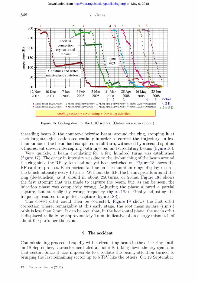
7. First cool down
The year 2008 was very eventful for the LHC. During the first half of the year,the whole machine was cooled down (figure 15). From room temperature to 80 K,the helium circulating in the magnets was cooled by vaporizing liquid nitrogenin a heat exchanger. In total, 1200 tonnes of liquid nitrogen was needed fora single sector, the whole process taking about 10 days with 60 trucks, eachcontaining 20 tonnes of liquid nitrogen, arriving every 4 h. Between 80 and 4.5 K,the helium refrigerators were used. Finally, the cold compressors producing heliumat 15 mbar pressure were switched on to reduce the temperature to the operatingvalue of 1.9 K.
8. First commissioning
By 10 September 2008, seven of the eight sectors had been successfullycommissioned to 5.5 TeV in preparation for a run at 5 TeV. Owing to lack of time,the eighth sector had only been taken to 4 TeV. Beam commissioning started by
Phil. Trans. R. Soc. A (2012)
on May 9, 2018http://rsta.royalsocietypublishing.org/Downloaded from
848 L. Evans
300
short inconnection
cryostats andrepairs
1 2 3 4 5 6 7 8
250
tem
pera
ture
(K
) 200
150
Christmas and watermaintenance shut-down
opendays
100
50
54321 sectors< 2 K
+ 2 < 5 K
0
cooling sectors + cryo tuning + powering activites
12 Nov2007
10 Dec2007
7 Jan2008
4 Feb2008
3 Mar2008
31 Mar2008
28 Apr2008
26 May2008
23 Jun2008
ARC56_MAGS_TTAVG.POSST
ARC67_MAGS_TTAVG.POSST
ARC78_MAGS_TTAVG.POSST
ARC34_MAGS_TTAVG.POSST
ARC81_MAGS_TTAVG.POSST
ARC12_MAGS_TTAVG.POSST
ARC23_MAGS_TTAVG.POSST
ARC45_MAGS_TTAVG.POSST
Figure 15. Cooling down of the LHC sectors. (Online version in colour.)
threading beam 2, the counter-clockwise beam, around the ring, stopping it ateach long straight section sequentially in order to correct the trajectory. In lessthan an hour, the beam had completed a full turn, witnessed by a second spot ona fluorescent screen intercepting both injected and circulating beams (figure 16).
Very quickly, a beam circulating for a few hundred turns was established(figure 17). The decay in intensity was due to the de-bunching of the beam aroundthe ring since the RF system had not yet been switched on. Figure 18 shows theRF capture process. Each horizontal line on the mountain range display recordsthe bunch intensity every 10 turns. Without the RF, the beam spreads around thering (de-bunches) as it should in about 250 turns, or 25 ms. Figure 18b showsthe first attempt that was made to capture the beam, but, as can be seen, theinjection phase was completely wrong. Adjusting the phase allowed a partialcapture, but at a slightly wrong frequency (figure 18c). Finally, adjusting thefrequency resulted in a perfect capture (figure 18d).
The closed orbit could then be corrected. Figure 19 shows the first orbitcorrection where, remarkably at this early stage, the root mean square (r.m.s.)orbit is less than 2 mm. It can be seen that, in the horizontal plane, the mean orbitis displaced radially by approximately 1 mm, indicative of an energy mismatch ofabout 0.9 parts per thousand.
9. The accident
Commissioning proceeded rapidly with a circulating beam in the other ring until,on 18 September, a transformer failed at point 8, taking down the cryogenics inthat sector. Since it was impossible to circulate the beam, attention turned tobringing the last remaining sector up to 5 TeV like the others. On 19 September,
Phil. Trans. R. Soc. A (2012)
on May 9, 2018http://rsta.royalsocietypublishing.org/Downloaded from

Review. The Large Hadron Collider 849
Figure 16. Beam on turns 1 and 2. (Online version in colour.)
LHC longitudinal bunch profile beam2
Figure 17. A few hundred turns. (Online version in colour.)
Phil. Trans. R. Soc. A (2012)
on May 9, 2018http://rsta.royalsocietypublishing.org/Downloaded from

850 L. Evans
(a) (b)
(c) (d)
Figure 18. (a) No RF, de-bunching in approximately 25 × 10 turns, i.e. approximately 25 ms. (b)First attempt at capture, at exactly the wrong injection phase. (c) Capture with corrected injectionphase but wrong frequency. (d) Capture with optimum injection phasing, correct reference. (Onlineversion in colour.)
the last remaining circuit was being ramped to full field when, at 5.2 TeV, acatastrophic rupture of a bus bar occurred causing extensive damage in sector34. These bus bars are connected by induction brazing with three layers oftin/silver solder in a copper box. Initially, it was foreseen to clamp these bus barsmechanically as well as with the solder, but this was discarded on the groundsthat it would increase the hydraulic impedance in the interconnect region andtherefore reduce the effectiveness of conduction cooling in the superfluid helium.
A fact-finding commission was established which concluded that the mostprobable cause of the accident was too high a resistivity in one of the 10 000superconducting bus bar joints owing to the omission of the solder. In a normalmachine, this would have caused minor damage. However, the joint ruptureresulted in an arc piercing the helium vessel. The resultant high pressure in the
Phil. Trans. R. Soc. A (2012)
on May 9, 2018http://rsta.royalsocietypublishing.org/Downloaded from

Review. The Large Hadron Collider 851
Figure 19. Corrected closed orbit on B2. Energy offset of approximately −0.9 parts per thousandowing to the capture frequency. (Online version in colour.)
insulating vacuum and the volume of helium gas was too high for the rupture discsto take, resulting in overpressure and displacement of magnets off their jacks. Intotal, 14 quadrupoles and 39 dipoles needed replacing.
10. The search for further defects
An urgent priority after the accident was to sift through data gathered during theevent to see if any precursors to the accident could be detected, in particular anyanomalous temperature increase in the affected area. Detecting temperature risein the superfluid helium is made difficult for two reasons. The first is the enormousthermal conductivity of superfluid helium (figure 20). This provides good coolingof joints initially, but, since it is a quantum liquid, the thermal conductivity is afunction of heat flux density (figure 21); therefore, as the heating increases, thecooling capacity quickly collapses, especially in the region of the splices with highhydraulic impedance.
The other reason why it was impossible to observe a temperature rise was theconfiguration of the superfluid cooling circuits themselves. Figure 22 shows onecryogenic cell containing two 107 m long periods of the machine. The primarysuperfluid flows through bayonet heat exchangers, the flow rate being controlledthrough JT valves (CV910 in the diagram). These valves are in a servo loop,which keeps the temperature constant.
It was obviously very important to find a way to be sure that there were nomore bad joints in the machine. Two methods were developed. The first of theserelied on calorimetry. With the servo loops open, the valves could be adjustedto just balance the static heat in-leak. Under these conditions, it was shownthat a calibrated heat in-leak of 10 W through a resistor could be detected and,by measuring the rate of temperature rise in the cell (figure 23), the original10 W could be reconstituted purely calorimetrically. Note the temperature axiswith 5 mK ticks! Once this calibration was made, a sector was powered to5 kA with the JT valves in an open loop adjusted to balance the static heatload. The normal signal to be expected during a current cycle is a slight
Phil. Trans. R. Soc. A (2012)
on May 9, 2018http://rsta.royalsocietypublishing.org/Downloaded from

852 L. Evans
2000
Y(T
) ± 5
%
K(T,q) = q–2.4 Y(T )
X in cmT in Kq in W cm–2
dT q3.4
dX Y(T)1500
1000
500
01.3 1.4 1.5 1.6 1.7 1.8
T (K)1.9
OFHC copper
helium II
2.0 2.1 2.2
Tl
=
Figure 20. Equivalent thermal conductivity of He II. (Online version in colour.)
104
103
Ke
(W c
m–1
K)
q = 0.5 W cm–2
1 = W cm–2
2 = W cm–2
1.6 1.7 1.8T (K)
1.9 2.0 2.1 Tl
102
Figure 21. Effective thermal conductivity of He II.
heating during ramp and de-ramp owing to eddy currents and slow coolingon flat top. Figure 24 shows a cell in which this was not the case. The slowmonotonic heating on flat top was consistent with a 100 nU resistance somewherein the cell.
Every magnet is equipped with a card containing an analogue-to-digitalconverter and a buffer memory in order to measure voltages, usually on atrigger due to a quench. It was realized that these cards could also be used to
Phil. Trans. R. Soc. A (2012)
on May 9, 2018http://rsta.royalsocietypublishing.org/Downloaded from

Review. The Large Hadron Collider 853
saturated LHe IIHX
Q Q Q QD D D D D D Dbayonet HX
supply pipe
hydraulic restriction(cutting conduction in He II
with respect to adjacent sub-sectors)
D D D D DTT911CV910
principle:
blocking of the JT valve (CV910) at a value to extract the static heatin-leaks before the powering
—
— then, the temperature drift is mainly due to electrical resistiveheating dissipated during the powering
Figure 22. Sub-sector magnet cooling scheme. The system normally operates in a closed loop withthe valve CV910 varied to keep the temperature constant. HX, heat exchanger. (Online versionin colour.)
1.920LQATO_15R1_TT821.POSST
LBARA_16R1_TT821.POSST
LBBRA_16R1_TT821.POSST
LBBRA_17R1_TT821.POSST
LBBRA_18R1_TT821.POSST
LBBRA_19R1_TT821.POSST
LBARA_19R1_TT821.POSST
LBBRD_19R1_TT821.POSST
Taverage
LBARB_18R1_TT821.POSST
LBBRD_17R1_TT821.POSST
LBARA_17R1_TT821.POSST
LBARA_18R1_TT821.POSST
LBARB_16R1_TT821.POSST
LQATH_16R1_TT821.POSST
LQATK_17R1_TT821.POSST
LQATH_18R1_TT821.POSST
1.915
tem
pera
ture
evo
lutio
n (K
)
1.910
1.905
1.900
1.895
1.890
1.885
1.8809.30 10.30 11.30
Figure 23. Experimental validation: temperature evolution. (Online version in colour.)
improve the signal-to-noise ratio in measuring voltages under DC conditions byaveraging, thereby opening up the possibility of making ohmic measurementsacross each splice. Figure 25 shows just such a measurement of all the jointsin the dipole chains of sectors 67 and 78 during a stepwise current ramp to5 kA. In sector 67, there is one anomaly visible with a resistance of 47 nU. Itwas possible to locate exactly which splice was responsible. Both the 100 nUsplice previously mentioned and the 47 nU splice were inside magnets which had
Phil. Trans. R. Soc. A (2012)
on May 9, 2018http://rsta.royalsocietypublishing.org/Downloaded from

854 L. Evans
1.92 6000
5000
4000
3000
2000
1000
0
–1000
1.91
1.90
tem
pera
ture
evo
lutio
n (K
)
curr
ent (
A)
1.89
1.88
1.8714.00 15.00 16.00 17.00 18.00 19.00 20.00
LBARA_16R1_TT821.POSSTLBARA_17R1_TT821.POSST
LBARA_18R1_TT821.POSST
LBARA_19R1_TT821.POSST
LBARB_16R1_TT821.POSST
LBARB_18R1_TT821.POSST
LBARB_16R1_TT821.POSST
LBBRA_17R1_TT821.POSST
LBBRA_18R1_TT821.POSST
LBBRA_19R1_TT821.POSST
LBBRD_17R1_TT821.POSST
LBBRD_19R1_TT821.POSST
LQATH_16R1_TT821.POSST
LQATH_18R1_TT821.POSST
LQATK_17R1_TT821.POSST
LQATO_15R1_TT821.POSST
RPTE.UA23.RB.A12:1_MEAS
Figure 24. Powering example: 15R1 powering at 5000 A. The continuing rise in temperature duringflat top indicates a resistive element of 100 nU. (Online version in colour.)
already been tested to full current. They have both been removed and the badsplices confirmed. No other such splices have been detected anywhere else inthe machine.
However, during the removal of damaged magnets, it was discovered that, insome instances, solder had been leaking out of the interconnect joints duringbrazing, weakening the joints in case of a (very unlikely) bus bar quench.Consequently, it was decided to operate the LHC at reduced energy untiladditional consolidation can be made during a shutdown. This consolidation willconsist of strengthening the interconnects, increasing the number of rupture discsin sectors where it has not already been done and reinforcing the jacks at thevacuum barriers so that they can take higher differential pressure in case of avery unlikely further incident of this kind.
11. Re-commissioning
The repairs and hardware re-commissioning took until November 2009. In theshort time available until the end of that year, beams were accelerated to energyof 1.18 TeV, equivalent to a dipole current of 2 kA, and a small amount of physicsdata collection was done. On 30 March 2010, the first collisions were obtainedat a centre-of-mass energy of 7 TeV. Since then, operating time has been splitbetween machine studies and physics data collection.
The collimation system works very efficiently. Figure 26 shows a loss maparound the ring obtained by provoking beam loss. The losses are located preciselywhere they should be, with a factor of 10 000 difference between the losses on thecollimators and those in the cold regions of the machine.
Phil. Trans. R. Soc. A (2012)
on May 9, 2018http://rsta.royalsocietypublishing.org/Downloaded from

Review. The Large Hadron Collider 855
Figure 25. Snapshots in sectors 67 and 78 of all 154 dipoles during a current ramp to 5 kA—B32.R6with a high (47 nU, top trace) joint resistance between the poles of one aperture. (Online versionin colour.)
10–1
IR1
IR2factor 10 000
IR5IR8
10–2
10–3
beam
loss
(G
y s–1
)
10–4
10–5
10–6
10–7
10–8
10–90 5000 10 000 15 000
s (m)20 000 25 000
Figure 26. Loss maps for collimation. The peaks are at the locations of the primary collimators andsecondary aperture restrictions. Blue lines, cold; black lines, collimator; red lines, warm. (Onlineversion in colour.)
Phil. Trans. R. Soc. A (2012)
on May 9, 2018http://rsta.royalsocietypublishing.org/Downloaded from

856 L. Evans
lost or reflected
20 ns 20 ns5 ns 5 nstime
secondary electronsecondary electron
10 eV
10 eV
10 eV
5 eV5 eV
5 eV
200
eV
200
eV
200
eV
2 ke
V
2 ke
V phot
oele
ctro
n
g gg
Figure 27. The electron cloud effect. (Online version in colour.)
10–5
Beam cleaning 9–11 April 2011Fills 1683-1686-1689-1691-1692-1694-50 ns
y = 9 × 10⁻⁶e–0.135x
y = 2 × 10⁻⁷e–0.119x
y = 5 × 10⁻⁶e–0.136x
10–6
mba
r A
–1
10–7
10–8
0 5 10 15time (h)
20 25 30
VGPB.220.5L5.X
VGPB.2.5R3.R
VGPB.231.7R7.R
Expon. (VGPB.2.5R3.R)
Expon. (VGPB.220.1L5.X)
Expon. (VGPB.2.5L3.B)
VGPB.2.5L3.B
VGP.505.23R7.R
Figure 28. Improvement in vacuum pressure during ‘scrubbing’. (Online version in colour.)
The design of the LHC is based on more than 30 years of accumulatedknowledge of the behaviour of hadron storage rings. However, one new effectnever before observed in hadron machines needed to be brought under controlbefore it could be certain that the machine would reach its design objectives.This is the so-called electron cloud instability (figure 27), where electronsliberated by synchrotron radiation photons or ionization of residual gas areaccelerated towards the wall of the beam tube owing to the electric field ofthe bunched beam. Secondary electrons can be resonantly amplified by followingbunches, resulting in a thermal load on the cold beam pipe and instability. Thecure foreseen was the conditioning of the beam pipe (scrubbing) by the electroncloud in order to reduce the secondary emission yield. Figure 28 shows the result
Phil. Trans. R. Soc. A (2012)
on May 9, 2018http://rsta.royalsocietypublishing.org/Downloaded from

Review. The Large Hadron Collider 857
of a 16 h scrubbing run, where the beams are allowed to circulate with an intensityjust above the threshold of the electron cloud instability.
The reduction in electron activity can be observed as an order of magnitudereduction in vacuum pressure. After this treatment, the machine could operateat high intensity with a bunch separation of 50 ns.
The machine’s performance at this early stage is very impressive. A single beamlifetime of more than 1000 h has been observed, an order of magnitude better thanexpected, proving that the vacuum is considerably better than expected and alsothe noise level in the RF system is very low. A nominal bunch intensity of 1.1 ×10¹¹ has been achieved and the b∗ at the experimental collision points squeezedto 1.5 m. The closed orbit can be kept to better than 1 mm r.m.s. with very goodreproducibility. The number of bunches per beam is now being increased with theluminosity routinely exceeding 1033 cm−2 s−1.
12. Conclusions
Building the LHC has been a huge task spanning more than 15 years fromapproval to operation. Initial commissioning with the beam went extremelysmoothly. Circulating and captured beam were achieved in a record time. Thetwo-in-one structure of the magnets works exactly as predicted. The machine’soptics already look extremely good with the closed orbit corrected to less than1 mm r.m.s. It has been shown that ‘scrubbing’ efficiently reduces the secondaryemission yield of the beam screen to a point where the electron cloud instabilitycan be controlled.
The unfortunate splice incident created a lot of damage that had to be repaired.Two powerful diagnostic tools have been developed to detect bad splices and toallow a permanent monitoring during operation.
The machine is now running for physics at reduced energy. Some furtherconsolidation will be needed before it can be pushed up to full potential. Thiswill be done in a long shut-down once an adequate amount of data at 7 TeV arecollected.
The LHC is the most complex scientific instrument ever constructed. It has taken 15 years to buildand many problems have been encountered on the way. These have all been overcome, thanks to theresourcefulness and resilience of the people who built it, both inside CERN and in our collaboratinglaboratories around the world. Now the machine is moving into its operational phase. I am confidentthat an equally competent team will exploit it to its full potential in the coming years.
References
1 CERN. 2004 The LHC design report. Vol. 1. The LHC main ring. Report no. CERN-2004-003,CERN, Geneva, Switzerland.
2 Evans, L. (ed.) 2009 The large Hadron collider: a marvel of technology. Lausanne, Switzerland:EPFL Press.
3 Wojcicki, S. 2008 The supercollider: the pre-Texas days. A personal recollection of its birth andBerkeley years. In Reviews of accelerator science and technology, vol. 1 (eds A. W. Chao & W.Chou), p. 303. Singapore: World Scientific.
4 Wojcicki, S. 2009 The supercollider: the Texas days. A personal recollection of its short life anddemise. In Reviews of accelerator science and technology, vol. 2 (eds A. W. Chao & W. Chou),p. 265. Singapore: World Scientific.
Phil. Trans. R. Soc. A (2012)
on May 9, 2018http://rsta.royalsocietypublishing.org/Downloaded from

858 L. Evans
5 CERN. 1993 The large Hadron collider and the long-term scientific programme of CERN:executive summary. CERN/SPC/679, CERN/CC/2016, CERN, Geneva, Switzerland.
6 US Department of Energy. 1994 High energy physics advisory panel’s subpanel on vision for thefuture of high energy physics. DOE/ER-0614P, US Department of Energy, Washington, DC.
7 CERN. 1994 Hundredth session of the Council first part. CERN/2052, CERN, Geneva,Switzerland.
8 CERN. 1994 Hundredth session of the CERN Council second part. Resolution approval of theLarge Hadron Collider (LHC) project. CERN/2075, CERN, Geneva, Switzerland.
9 US Department of Energy. 1996 Assessment of the Large Hadron Collider. DOE/ER-0677, USDepartment of Energy, Washington, DC.
Phil. Trans. R. Soc. A (2012)
on May 9, 2018http://rsta.royalsocietypublishing.org/Downloaded from