OPERATOR’S MANUAL - Paintball Solutions · OPERATOR’S MANUAL. 2 ... - While pointing marker in...
18
1 OPERATOR’S MANUAL
Transcript of OPERATOR’S MANUAL - Paintball Solutions · OPERATOR’S MANUAL. 2 ... - While pointing marker in...

1
O P E R A T O R ’ S M A N U A L

2
Table of Contents
1. Introduction and Specifications pg.2
2. Rules for Safe Marker Handling pg.3
3. Basic Operation pg.3
4. Firing the Mini GS pg.5
5. Break Beam Eyes Operation pg.5
6. Regulator and velocity adjustmen pg.6
7. Shockwave board settings and functions pg.6
8. Trigger adjustments pg.9
9. Assembly/disassembly and maintenance pg.10
10. Storage and transportation pg.12
11. Troubleshooting guide pg.13
12. Diagrams and parts list pg.15
13. Warranty information pg.18
This is not a toy. Misuse may cause serious injury or death. Eye protection designed specifically for paintball must be worn by the user and persons within range. Recommend 18 years of age or older to purchase. Persons under 18 years of age must have adult supervision. READ THIS MANUAL BEFORE USING.
1. Introduction and Specifications
The Empire MINI marker is legendary in paintball, offering unrivaled performance and more supe-rior features than other markers in its class. The small size offers big performance and will make players ranging from beginners to experienced players happy in their choice of the MINI GS. The MINI GS is precision engineered from aircraft grade aluminum to meet the demands of the most competitive players, teams, and climates. The ultimate intent of the MINI GS is to exceed your expectations.
Empire Paintball expects you to play hard and play frequently and thus the MINI GS was built with this in mind. All internal parts, wear, and contact surfaces have been hard anodized. The toughest and most resilient materials and components have been used in the construction of this marker.
Empire Mini GS Specifications- Model: Empire MINI GS- 1-Piece Barrel: 12” Aluminum Ported- Caliber: .68- Action: Semi Auto, PSP and Millennium Ramping, and NXL Full Auto- Air Source: Compressed Air Only- Battery: One 9 Volt- Cycle Rate: 20 BPS (Semi-Auto only)- Main Body Material: Aluminum- Accuracy Range: 150+ ft- Weight: 1.90 lbs
Included with your Empire Mini GS- 12” Barrel (.688 bore)- Hex Keys- Spare Parts- Barrel Sleeve- One 9 Volt Battery (installed)

3
2. Rules for Safe Marker Handling
WARNING: Never carry your paintball marker uncased when not on a playing field. The non-playing public and law enforcement personnel may not be able to distinguish between a paintball marker and a firearm. For your own safety and to protect the image of the sport, always carry your marker in a suitable marker case or in the box in which it was shipped.
• Treat every marker as if it were loaded.• Never look down the barrel of a paintball marker.• Keep the marker in “Safe Mode” until ready to shoot, power Off and barrel blocking device installed in/on the marker’s Barrel.• Keep your finger off the Trigger until ready to shoot.• Never point the marker at anything you don’t wish to shoot.• Keep the barrel blocking device in/on the marker’s Barrel when not shooting.• Always remove paintballs and the air source before disassembly.• After removing the air source, point marker in safe direction and discharge until marker is degassed.• Store the marker unloaded and degassed in a secure place.• Follow warnings listed on the air source for handling and storage.• Do not shoot at fragile objects such as windows.• The operator and every person within range must wear eye, face and ear protection designed specifically to stop paintballs and meeting ASTM standard F1776.• Always measure your marker’s velocity before playing paintball and never shoot at velocities in excess of 300 feet-per-second (91.44 meters-per-second).• Read this entire manual before loading, attaching a propellant source or in any way attempting to operate the Empire Mini GS marker.
3. Basic Operation- Safety and safe marker handling are the most important aspects of paintball sports. Do not install compressed air or load paintballs into your MINI GS until you feel completely confident with your ability to handle your MINI GS safely.- Keep your finger out of the Trigger guard and away from the Trigger; point the muzzle of the marker in a safe direction at all times. Keep the marker turned off until ready to operate. The
MINI GS uses an On-Off button as one of its safety devices.- Always keep your MINI GS pointed in a safe direction. Always use a barrel plug or barrel blocking device.- Always use ASTM approved paintball specific eye protection in any areas where paintball markers may be discharged. Remember that the ultimate safety device is you, the operator.
Barrel Installation- While pointing marker in a safe direction, place the threaded end of the barrel into the front opening of the marker body.- Turn the barrel clockwise until it stops (do not over tighten).- Install a barrel-blocking device which is included. This can be a barrel plug or other such device that prevents the accidental discharge of paintballs.
Compressed Air/Nitrogen SupplyThe MINI GS is designed to work with Compressed Air/Nitrogen Only. Do Not use CO2, as it will damage your MINI GS.
Consult the place where you purchased your MINI GS, or a recognized and competent air smith, for instruction in the safe handling of compressed-air cylinders before purchasing or connecting one to your MINI GS.
The MINI GS utilizes a fully functional regulator at the bottom of the Grip Frame that doubles as an ASA (Air Source Adaptor) or receiver for a standard threaded pre-set output compressed air system. The regulator can function using either “high pressure” or “low pressure” air systems.
Note: If you are using an adjustable regulator system, the output pressure should be set between 350-450 psi.
Before Pressurizing your Mini GS- Check to make sure that you and anyone within range are wearing eye protection designed specifically for paintball.- Double check that all screws are tightened and no parts are loose before installing your tank.- Ensure you have a barrel plug, barrel sock or other specifically designed barrel-blocking device in place.- Make sure there are no paintballs in the marker and that the MINI GS is turned OFF.
Notes:- Remember compressed air or nitrogen systems can be extremely dangerous if misused or improperly handled. Use only cylinders meeting D.O.T, TC. or regionally defined specifications. Do not perform any work to your tank or tank regulator.- Never disassemble your tank or tank regulator. Only a qualified and trained technician should perform work on your tank and tank regulator.
- Never add any lubricants or greases into the fill adapter on your tank regulator or into the MINI GS’s regulator.

4
Pressurizing your Mini GS - Flip the regulator’s On/Off ASA lever forward so it’s pointing toward the front of the marker. - Install a compressed air tank, by screwing it in clockwise; making sure it’s fully threaded into the ASA. DO NOT USE CO2!- Flip the On/Off ASA lever back so it’s flush with the regulator and pointing toward the rear of the marker. (Fig. 3-1)- The marker will become pressurized.
Installing a Loader and PaintballsThe MINI GS comes equipped to accept 1.03” (outer dimension) standard loaders, whether gravity feed, agitating or force-feed loaders. Fit paintball outlet of the loader directly into the Feedneck. It might be necessary to adjust the clamp to your loader using the 3/32” hex wrench. Always twist the loader in a Clockwise direction to prevent feedneck thread damage.
The MINI GS uses .68 caliber, water-soluble paintballs, readily available at paintball pro-shops, commercial playing fields, and many sporting goods stores. The paintballs are fed from the loader through the direct vertical feed port and into the breech of the marker.
Switching On Your Mini GS- To switch the MINI GS On, locate the Power Button on the back side of the front Foregrip, in front of the Trigger guard and under the LED. (Fig 3-2)- Push and hold the button for 2 seconds. The LED will glow solid RED as soon as the button is pressed. Continue to hold the button until the LED glows solid GREEN. - Release button and the LED will intermittently flash indicating that the marker is now ON and LIVE in FIRE Mode. - The LED color will be determined by the battery level, as listed in the chart described under the Battery Life Indicator section of this manual.
NOTE: Be sure not to have the Trigger pressed when turning the board on, as this will enter the board into Settings Mode.
LED INDICATIONThe LED indicator, located above the button, is used to indicate the current Break Beam Sensor System status, the Battery Life Indicator and Trigger Pull indication. The Break Beam Sensor Status is indicated by the blinking frequency of the LED (See Section 5 for further explanation). If the Trigger is being pressed the LED will glow a dim RED which can be seen between blinks of the LED.
BATTERY LIFE INDICATORThe MINI GS also has a Battery Life Indicator, shown by the LED located on the back of the Fore-grip. If in standard operation and the LED flashes with a GREEN color, then the battery is Good. If the LED flashes YELLOW/AMBER, then the battery is fairly depleted and should be replaced soon. If the LED flashes RED, the there is less than 20% of the full battery strength remaining and should be replaced immediately. Battery Level is indicated by the color of the LED (see table below for explanation)
- LED Color.......................... Battery Level- GREEN............................... Battery Good- YELLOW/AMBER..............Low Battery, should replace- RED.................................... Battery depleted replace immediately
NOTE: During rapid firing, the battery can be depleted quickly and the LED may change color and give an incorrect read-
ing. Allow time for the battery to recover before determining if the battery life is good or truly depleted.
BATTERY REPLACEMENTThe MINI GS requires a single 9-volt battery as the electronic power source. The use of long life, name-brand alkaline batteries is recommended for optimum performance. The 9-volt battery is located in the front Foregrip in front of the Trigger Guard. The battery is accessed by removing the front rubber Grip.
Confirm that the marker is Off. Remove the two screws that secure the front rubber grip to the left-hand side of the Foregrip. Peel back the rubber grip to access the battery compartment un-derneath. If there is already a battery in the Foregrip, gently remove the battery, and then connect a fresh 9-Volt battery into the compartment following the polarity markings for positive (+) and negative (-). (Fig 3-3) Then re-install the front rubber Grip and screw it securely into place.
(Fig. 3-1)
(Fig. 3-2)

5
Note: Some rechargeable batteries are too large for the MINI GS battery compartment. If they don’t fit, please don’t force them as this may damage the board.
SWITCHING OFF YOUR MINI GSPush and hold the button on the front Foregrip. After the button is held for 2 seconds, the LED will turn to a solid RED color. Release button and the MINI GS will switch Off.
AUTOMATIC OFF FEATUREThe MINI GS also has an “Automatic OFF” feature. If you leave your MINI GS powered up, it will shut itself off after approximately 60 minutes of inactivity. This time cannot be adjusted.
EYE FUNCTIONThe MINI GS board is pre-programmed to activate the eye system each time the marker is pow-ered up. See Section 5 (Break Beam Eyes Operation) for more details.
4. FIRING THE MINI GSKeep your finger out of the Trigger Guard and away from the Trigger, point the barrel of your marker in a safe direction at all times during this process. Be sure your goggles are securely in place and make sure the MINI GS marker is OFF.
WARNING- Everyone within firing range should always use paintball approved eye and face protec-tion in the presence of live paintball markers.
- Place the empty loader onto the marker.- Be sure that it is securely mounted in place.- Apply the compressed gas, pressurizing the marker.- Put the paintballs into the loader.- Remove the barrel plug, sock or barrel-blocking device.- Aim the MINI GS in a safe direction.- Turn the MINI GS ON: Push the button for 2 seconds until the LED light changes to solid GREEN, then release button and LED should display a flashing LED according to Eye Status- Aim the MINI GS at the target.- Pull the Trigger with a smooth squeezing motion.
5. BREAK BEAM EYES OPERATIONThe MINI GS uses a break beam eye system to determine the absence or presence of a paintball in the breech for the purposes of reduced paint breakage and optimum rates of fire. When the break beam system is activated the marker will not fire unless the break beam system detects a paintball. The MINI GS board is pre-programmed to activate the eye system each time the marker is powered up.
To turn the eyes OFF, ensure that there are no paintballs in the MINI GS breech or feed-neck, make sure the marker is switched On, and then tap the button once. A fast, flashing LED will indicate that the eye system has been deactivated.
To turn the eyes back ON, tap the button one time.
A slow consistent single blinking Green LED indicates that the eyes are ON with no ball in the breech and a double blink LED indicates that there is a ball in the breech.
If the Break Beam Eye System malfunctions, the marker assumes there was a ball broken and the Rate of Fire (ROF) is limited to 8.0 balls-per-second (bps) to prevent further ball breaks. The LED indicator will flash slowly. Turn the Break Beam Eye System OFF to allow firing at Max ROF cap setting. Break Beam Sensor Status is indicated by blinking frequency of the LED (See table below for explanation). Color would be determined by battery level, as listed in the chart in Section 3.
- Blink Frequency.................................. Break Beam (BB) Eye Status- Single Blink......................................... BB Sensor System active, no ball in breech- Double Blink....................................... BB Sensor System active, ball in breech- Flashing...............................................BB Sensor System has malfunctioned- Fast Flashing.......................................BB Sensor System Deactivated
For optimal performance of the MINI GS eyes, keep the inside of the MINI GS breech clean and clear of broken paint, paint residue, or other debris. Although the eyes can be cleaned via clean-ing the breech of the MINI GS marker, if the eye board needs to be accessed, please follow the steps outlined in the Main Body Assembly section of this manual.
TRIGGER PULL INDICATIONIf the Trigger is being pressed, the LED will display a dim Red LED which can be seen between blinks of the Eye Setting LED.
(Fig. 3-3)

6
6. REGULATOR AND VELOCITY ADJUSTMENTThe MINI GS utilizes a fully functional Bottomline Regulator at the bottom of the Grip Frame that doubles as an ASA adaptor/receiver for a standard threaded pre-set output compressed air sys-tem. This unique regulator system channels air through a chamber in the Grip Frame eliminating the need for external macroline and fittings. The Bottomline Regulator controls the amount of air pressure going from your compressed air system into the marker itself.
The MINI GS regulator should be pre-set at 200 PSI, as this is the best operating pressure for firing the marker. However, if over time you do need to adjust the pressure, only use the Regula-tor Adjuster Screw on the front of your Bottomline Regulator. Never adjust the regulator above 210psi.
REGULATOR ADJUSTMENTIf adjustments are needed use a 3/32” hex wrench and insert it into the regulator adjustment screw. This is located in the front of the regulator.(Fig 6-1)
- Increase pressure turn Clockwise.- Decrease pressure turn Counter-clockwise.
Notes:- Always watch the gauge as you are adjusting the pressure.- Do NOT use CO2!!!- The Bottomline Regulator should not be disassembled.- Never set the regulator above 210 psi.
ADJUSTING THE VELOCITYAt the back of the MINI GS main Body is the Bolt Guide Cap. The hex screw in the Bolt Guide Cap serves as your velocity adjuster. Confirm that the pressure on your Bottomline Regulator is at or below 200 PSI. Then you can increase or decrease the velocity on your MINI GS by tightening or loosening the velocity adjustment screw with a 3/32” inch hex wrench. (Fig 6-2) A paintball specific radar chronograph should be used to accurately measure your velocity.
- Increase VelocityUnscrew or loosen the velocity adjustment screw by turning it counterclockwise.Rotate the velocity adjustment screw counter-clockwise in small increments (1/4 turn or less), stopping between slight turns to test velocity, until desired velocity is achieved. Do not back the adjuster out past being flush.Stop if you hear an air leak, and adjust back in a 1/4 turn.
- Decrease VelocityTighten or screw-in the velocity adjustment screw by turning it Clockwise. Rotate the velocity adjustment screw Clockwise in small increments (1/4 turn or less), stopping between slight turns to test velocity, until desired velocity is achieved.
Notes:- This marker was designed with safety and safety standards in mind. If you attempt to shoot paintballs at a higher velocity than established safety standards, the marker may not function properly.- If you attempt to operate the marker at extremely high velocities, the internals will not function properly.- This marker is not designed to shoot above the safety limits established by industry standards but under certain conditions it may. It is therefore important to check the velocity each time before playing with your Mini.
7. SHOCKWAVE BOARD SETTINGS AND FUNCTIONSThe electronic board features several modes and functions that are listed below. The board is located inside the front Foregrip of the marker. Before changing or adjusting any of the board functions, remove the propellant source from the MINI GS and install a barrel blocking device. The board inside your MINI GS features 4 firing modes and 6 adjustable functions. It uses a 3 color LED indicator on the backside of the front Foregrip to indicate functions and modes during programming.
TOURNAMENT LOCK Tournament lock is a feature that prevents the marker from entering the Settings Mode while in the field, to allow the marker to be tournament legal. See your tournament’s rule book for an explanation on what is required to lock your marker. Tournament Lock can be turned on/off by using the dip switch 1 located on the inside of the Foregrip near the bottom of the circuit board.Flip dip switch #1 to the ON (UP when laying flat) position to activate the Tournament Lock. (Fig 7-1) When tournament lock is ON, Settings Mode cannot be activated
SETTINGS MODEThe MINI GS must be Off and the Tourna-ment Lock must be Off to begin managing the settings and functions. To activate the marker in Settings Mode, press and hold the Trigger, then press and hold the button on the back side of the Foregrip. The LED will cycle through an array of colors to indicate the Settings mode is active. You may now release the Trig-ger and the button. Once the LED is done cycling you are ready to navigate through settings mode.(Fig. 6-2)
(Fig. 7-1)
(Fig. 6-1)
7
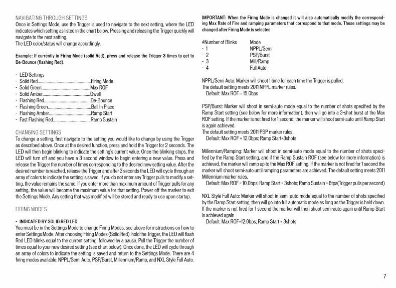
NAVIGATING THROUGH SETTINGSOnce in Settings Mode, use the Trigger is used to navigate to the next setting, where the LED indicates which setting as listed in the chart below. Pressing and releasing the Trigger quickly will navigate to the next setting.The LED color/status will change accordingly.
Example: If currently in Firing Mode (solid Red), press and release the Trigger 3 times to get to De-Bounce (flashing Red).
- LED Settings- Solid Red................................................Firing Mode- Solid Green............................................Max ROF- Solid Amber...........................................Dwell- Flashing Red..........................................De-Bounce- Flashing Green.......................................Ball In Place- Flashing Amber......................................Ramp Start- Fast Flashing Red..................................Ramp Sustain
CHANGING SETTINGSTo change a setting, first navigate to the setting you would like to change by using the Trigger as described above. Once at the desired function, press and hold the Trigger for 2 seconds. The LED will then begin blinking to indicate the setting’s current value. Once the blinking stops, the LED will turn off and you have a 3 second window to begin entering a new value. Press and release the Trigger the number of times corresponding to the desired new setting value. After the desired number is reached, release the Trigger and after 3 seconds the LED will cycle through an array of colors to indicate the setting is saved. If you do not enter any Trigger pulls to modify a set-ting, the value remains the same. If you enter more than maximum amount of Trigger pulls for any setting, the value will become the maximum value for that setting. Power off the marker to exit the Settings Mode. Any setting that was modified will be stored and ready to use upon startup.
FIRING MODES
- INDICATED BY SOLID RED LEDYou must be in the Settings Mode to change Firing Modes, see above for instructions on how to enter Settings Mode. After choosing Firing Modes (Solid Red), hold the Trigger, the LED will flash Red LED blinks equal to the current setting, followed by a pause. Pull the Trigger the number of times equal to your new desired setting (see chart below). Once done, the LED will cycle through an array of colors to indicate the setting is saved and return to the Settings Mode. There are 4 firing modes available: NPPL/Semi Auto, PSP/Burst, Millennium/Ramp, and NXL Style Full Auto.
IMPORTANT: When the Firing Mode is changed it will also automatically modify the correspond-ing Max Rate of Fire and ramping parameters that correspond to that mode. These settings may be changed after Firing Mode is selected
#Number of Blinks Mode- 1 NPPL/Semi- 2 PSP/Burst- 3 Mill/Ramp- 4 Full Auto
NPPL/Semi Auto: Marker will shoot 1 time for each time the Trigger is pulled.The default setting meets 2011 NPPL marker rules. Default: Max ROF = 15.0bps
PSP/Burst: Marker will shoot in semi-auto mode equal to the number of shots specified by the Ramp Start setting (see below for more information), then will go into a 3-shot burst at the Max ROF setting. If the marker is not fired for 1 second, the marker will shoot semi-auto until Ramp Start is again achieved.The default setting meets 2011 PSP marker rules. Default: Max ROF = 12.0bps; Ramp Start=3shots
Millennium/Ramping: Marker will shoot in semi-auto mode equal to the number of shots speci-fied by the Ramp Start setting, and if the Ramp Sustain ROF (see below for more information) is achieved, the marker will ramp up to the Max ROF setting. If the marker is not fired for 1 second the marker will shoot semi-auto until ramping parameters are achieved. The default setting meets 2011 Millennium marker rules. Default: Max ROF = 10.0bps; Ramp Start = 3shots; Ramp Sustain = 6tps(Trigger pulls per second)
NXL Style Full Auto: Marker will shoot in semi-auto mode equal to the number of shots specified by the Ramp Start setting, then will go into full automatic mode as long as the Trigger is held down. If the marker is not fired for 1 second the marker will then shoot semi-auto again until Ramp Start is achieved again Default: Max ROF=12.0bps; Ramp Start = 3shots

8
MAX RATE OF FIRE (ROF)
- INDICATED BY SOLID GREEN LEDThis setting controls the maximum number of paintball per second the marker is allowed to fire. The setting can be varied from 8 to 20 balls per second (bps) in 0.5bps intervals. Use the chart below to set the Max ROF. Default: Max ROF = 15.0 bps
You must be in the Settings Mode to change the Max ROF, see above for instructions on how to enter Settings Mode. After choosing Max ROF Mode (Solid Green), hold the Trigger to get into the Mode, the LED will flash GREEN LED blinks equal to the current setting, followed by a pause. Pull the Trigger the number of times equal to your new desired setting (see chart below). Once done, the LED will cycle through an array of colors to indicate the setting is saved and return to the Settings Mode. Example: 10 LED blinks = 12.5 BPS
# of Blinks BPS Value # of Blinks BPS Value # of Blinks BPS Value1 8.0 10 12.5 18 16.52 8.5 11 13.0 19 17.03 9.0 12 13.5 20 17.54 9.5 13 14.0 21 18.05 10.0 14 14.5 22 18.56 10.5 15 15.0 23 19.07 11.0 16 15.5 24 19.58 11.5 17 16.0 25 20.09 12.0
DWELL SETTING
- WILL BE INDICATED BY SOLID AMBER LEDThis setting controls the amount of time the solenoid valve is left open. A setting too high will waste excess gas and affect efficiency. A setting too low will prevent marker from operating properly. It is not recommended to change this setting unless you are an experienced user. Mini-mum dwell time is 3.0ms and is increased in .5ms increments up to 10ms. Use the chart below to set the Dwell. Default: Dwell = 8.0 ms
You must be in the Settings Mode to change the Dwell Setting, see above for instructions on how to enter Settings Mode. After choosing Dwell Setting (Solid Amber), hold the Trigger to get into the Mode, the LED will flash Amber LED blinks equal to the current setting, followed by a pause. Pull the Trigger the number of times equal to your new desired setting (see chart below). Once done, the LED will cycle through an array of colors to indicate the setting is saved and return to the Settings Mode.
# of Blinks Dwell in ms # of Blinks Dwell in ms1 3.0 9 7.02 3.5 10 7.53 4.0 11 8.04 4.5 12 8.55 5.0 13 9.0 6 5.5 14 9.57 6.0 15 10.08 6.5
TRIGGER DE-BOUNCE
- WILL BE INDICATED BY A FLASHING RED LEDTime in milliseconds the Trigger pull must be released before the next Trigger pull can be reg-istered. This eliminates electronic noise and vibrations (“Trigger Bounce”) that the board may wrongly interpret as a Trigger action (Trigger pull) and fire the marker. A higher setting will reduce the bounce. A lower setting will allow for more bounce. One blink corresponds to 1ms of De-Bounce time. De-Bounce is adjustable from 1-15ms in 1.0ms increments. Default: De-Bounce = 5.0 ms
You must be in the Settings Mode to change the De-Bounce Setting, see above for instructions on how to enter Settings Mode. After choosing De-Bounce Setting (Flashing Red), hold the Trig-ger to display the value, the LED will show flashing Red LED blinks equal to the current value, followed by a pause. Pull the Trigger the number of times equal to your new desired setting, one pull per desired setting equal to each millisecond. Once done, the LED will cycle through an array of colors to indicate the setting is saved and return to the Settings Mode.
BALL IN PLACE (BIP) DELAY
- WILL BE INDICATED BY A FLASHING GREEN LEDTime in milliseconds the ball must stay in breech before it can be fired. Increase this setting for slower feeding loaders to avoid chopping balls in the breech. Faster force feed loader systems

9
may allow for a lower setting to help achieve higher rates of fire. BIP Delay is adjustable from 1-40ms in 1.0ms increments. Default: BIP Delay = 5.0ms
Note: If you are not using a force-feed loader, it is recommended that you use a higher BIP setting.
You must be in the Settings Mode to change the BIP Delay Setting, see above for instructions on how to enter Settings Mode. After choosing BIP Delay (Flashing Green), hold the Trigger to get into the Mode, the LED will show flashing Green LED blinks equal to the current setting, followed by a pause. Pull the Trigger the number of times equal to your new desired setting, one pull per desired setting equal to each millisecond. Once done, the LED will cycle through an array of colors to indicate the setting is saved and return to the Settings Mode.
RAMP START
- INDICATED BY A FLASHING AMBER LEDThis setting controls the amount of semi-automatic shots must be fired before ramping will start. If the marker is not fired for 1 second the count will start over. Ramp Start is adjustable from 1-12 shots in 1 shot increments. Default: Ramp Start = 3 Shots
You must be in the Settings Mode to change the Ramp Start Setting, see above for instructions on how to enter Settings Mode. After choosing Ramp Start (Flashing Amber), hold the Trigger to get into the Mode, the LED will show flashing Amber LED blinks equal to the current setting, fol-lowed by a pause. Pull the Trigger the number of times equal to your new desired setting, one pull per desired setting equal to one shot. Once done, the LED will cycle through an array of colors to indicate the setting is saved and return to the Settings Mode.
RAMP SUSTAIN
- INDICATED BY A FAST FLASHING RED LEDThis settings controls the amount of Trigger pulls per second (TPS) that must be achieved and sustained for ramp to kick in. Ramp Sustain is adjustable from 1-12 Trigger-pulls-per-second (tps) in 1 tps increments. Default: Ramp Sustain = 3 tps
You must be in the Settings Mode to change the Ramp Sustain Setting, see above for instruc-tions on how to enter Settings Mode. After choosing Ramp Sustain (Fast Flashing Red), hold the Trigger to get into the Mode, the LED will show fast flashing Red LED blinks equal to the current setting, followed by a pause. Pull the Trigger the number of times equal to your new desired set-
ting, one pull per each TPS. Once done, the LED will cycle through an array of colors to indicate the setting is saved and return to the Settings Mode.
Note: This setting affects only Millennium/ Ramp Firing Mode.
FACTORY RESETThe board has a feature that allows the user to reset all of the settings back to the stock configu-ration. Tournament Lock must be off to perform factory reset. The following steps are required to perform a Factory Reset:1. With board Off, turn marker On in settings mode.2. Press and hold the button on the Foregrip, then press and hold the Trigger so that both the button and Trigger are being held simultaneously (Note: button must be pressed first).3. Hold both the button and Trigger for approximately 5-6 seconds. The LED will then start alter nating green and red. Now release the button and Trigger.4. When the board is done resetting the board will turn off.
8. TRIGGER ADJUSTMENTSThe LED is also used to indicate Trigger pulls. When no Trigger pull is recognized, the LED flash-es normally based on the status of the eyes and the battery power level. When a Trigger pull is activated, the LED will change to a dim RED Led for each Trigger pull. Before making any Trigger adjustments, it is recommended to de-gas the MINI GS, then switch On the circuit board with eyes turned Off to easily monitor the current activation point.
You will notice there are four (4) adjustment points for your Trigger. (Fig 8-1) These can be adjusted with a 5/64” hex wrench.
- The first set screw (1) is located at the top front of the Trigger, hidden by the Grip Frame. This set screw adjusts forward/release stop point.- The second set screw (2) is located at the middle of the Trigger (without the magnet). This is used to adjust rear movement range, and stop point.- The bottom-most set screw (with magnet)(3) is the return force/magnetic tension.- The third set screw is located in the top, behind the Trigger and hidden by the Grip Frame. This set screw adjusts the Trigger activation point. For best results, the activation point should be set right in the middle of the total Trigger movement from front to back.- A fourth set screw adjusts the Activation Point as in only accessable by removing the Trigger from the Grip Frame.
(Fig. 8-1)
10
Notes:- Normal activity may cause set screws to back out of adjustment. If necessary it is OK to use blue Loctite® or similar thread-locking product on your Trigger set screws. However, do not use an excessive amount. Make sure you make your adjustments carefully, and clean up any extra Loctite. Also, allow it to dry several hours before using your MINI GS.- If any of the set screws are over adjusted in any direction, the MINI GS may not fire.- If the Trigger travel is adjusted too short, the Mini may fire on its own, repeatedly, and/or uncontrollably.
9. ASSEMBLY/DISASSEMBLY AND MAINTENANCECAUTION: Before attempting to perform any maintenance operations or any marker disassem-bly, make sure that all paintballs and propellant sources have been removed from the marker and that the regulator gauge reads 0 psi. Install a barrel blocking device, push Power button and hold for over 2 seconds until the LED light glows solid RED, and keep the MINI GS powe Off.
GENERAL MAINTENANCEKeep your MINI GS clean and lubricated to eliminate the friction that would prevent reliable oper-ation. Clean and lube the marker before each use, and do not put it away dirty. USE NO OILS! Do not use oils made for paintball markers, real firearms or pneumatic tools, do not use oils at all. Do NOT use petroleum-based lubricants in the lubrication of this marker. Under any circumstances, DO NOT use a solvent-based lubricant. Teflon or silicone (Non-spray only) lubricants designed for use on O-rings may be used for lubrication for the bolt area only of the main housing. Only use Paintball specific marker grease, such as Empire marker grease. The following maintenance procedures described below should be performed before each day of use or every 20,000 shots, whichever comes first.
REMOVAL OF BOLT AND BOLT GUIDE ASSEMBLY- Using a 3/32” hex wrench, insert it into the rear frame screw, turn the hex wrench counter- clockwise and completely remove the screw. (Fig 9-1)- This will allow you to pull out the Bolt and Bolt Guide Assembly. If assembly does not easily slide out, insert a barrel swab into the front of the Body and push out the Bolt/Bolt Guide Assembly. (Fig 9-2)
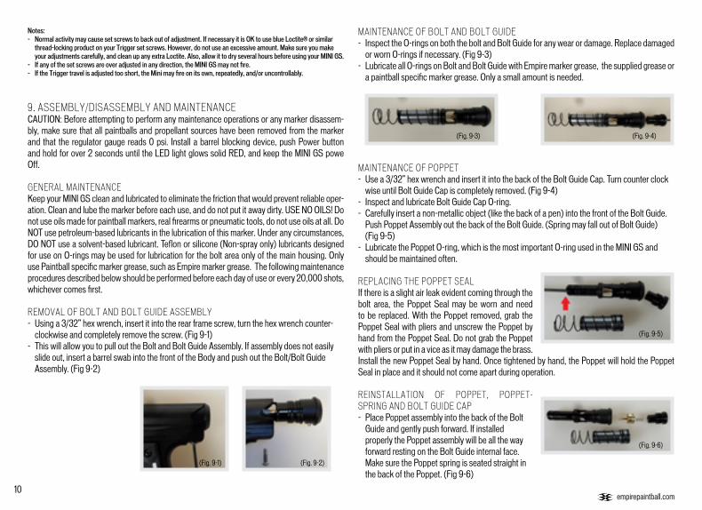
MAINTENANCE OF BOLT AND BOLT GUIDE- Inspect the O-rings on both the bolt and Bolt Guide for any wear or damage. Replace damaged or worn O-rings if necessary. (Fig 9-3)- Lubricate all O-rings on Bolt and Bolt Guide with Empire marker grease, the supplied grease or a paintball specific marker grease. Only a small amount is needed.
MAINTENANCE OF POPPET- Use a 3/32” hex wrench and insert it into the back of the Bolt Guide Cap. Turn counter clock wise until Bolt Guide Cap is completely removed. (Fig 9-4)- Inspect and lubricate Bolt Guide Cap O-ring.- Carefully insert a non-metallic object (like the back of a pen) into the front of the Bolt Guide. Push Poppet Assembly out the back of the Bolt Guide. (Spring may fall out of Bolt Guide) (Fig 9-5)- Lubricate the Poppet O-ring, which is the most important O-ring used in the MINI GS and should be maintained often.
REPLACING THE POPPET SEALIf there is a slight air leak evident coming through the bolt area, the Poppet Seal may be worn and need to be replaced. With the Poppet removed, grab the Poppet Seal with pliers and unscrew the Poppet by hand from the Poppet Seal. Do not grab the Poppet with pliers or put in a vice as it may damage the brass. Install the new Poppet Seal by hand. Once tightened by hand, the Poppet will hold the Poppet Seal in place and it should not come apart during operation.
REINSTALLATION OF POPPET, POPPET-SPRING AND BOLT GUIDE CAP- Place Poppet assembly into the back of the Bolt Guide and gently push forward. If installed properly the Poppet assembly will be all the way forward resting on the Bolt Guide internal face. Make sure the Poppet spring is seated straight in the back of the Poppet. (Fig 9-6)
(Fig. 9-2)
(Fig. 9-3)
(Fig. 9-5)
(Fig. 9-6)
(Fig. 9-4)
(Fig. 9-1)

11
- Using the 3/32” hex wrench, screw the Bolt Guide Cap clockwise back into the Bolt Guide. Screw the Bolt guide cap all the way in, then turn out 1/2 turn. Further adjustment over a chronograph will be needed to achieve desired velocity.
REINSTALLATION OF MAIN SPRING, BOLT AND BOLT GUIDE ASSEMBLYSlide main spring onto bolt, and then bolt onto Bolt Guide, so it is one assembly. You will notice, one end of the spring is smaller and will lock onto the bolt. Insert assembly into the back of Body. (Fig 9-7)
Note: - On the bottom side of the Bolt Guide there is a small alignment pin at the rear of Bolt Guide. This must line up with the alignment hole.- Holding the bolt assembly tight into the back of the Body with one hand, re-install the rear frame screw and tighten using the 1/8” hex wrench.
REMOVAL OF FOREGRIP ASSEMBLYNote: Be careful with the Battery wires when removing the Foregrip.
- Using a 5/64” hex wrench, loosen and remove the four screws holding the rubber Grip onto the Foregrip.- There are five screws that hold the Foregrip to the Grip Frame and Transfer Plate.- Locate the two screws near the corners of the Trigger Guard, one on each side of the Mini GS. Use a 5/64” hex wrench to remove those screws.- There are three screws located on the front of the Foregrip. One in the center at the very top and two at the bottom. Remove them using a 3/32” hex wrench- Carefully unplug the Battery Harness from the board. Do not pull the wires or they may break off the battery contacts.- The Foregrip assembly will now life free of the Grip Frame. (Fig 9-8)
INSTALLATION OF FOREGRIPTo reinstall the Foregrip Assembly onto the Grip Frame and Body. - Connect the Battery Harness from the Foregrip into the Board on the Grip Frame.- Slide the Foregrip assembly back over the board and onto the Grip Frame, aligning the screw holes.- Install the three front screws using the 3/32” hex wrench and the two side screws using the 5/64” hex wrench.- Re-install the rubber Grip using the four screws and a 5/64” hex wrench.
Note: If not installed correctly, you might damage the Circuit Board!
REMOVAL OF GRIP FRAME- Using a 5/64” hex wrench, loosen and remove the four screws holding the rubber Grip onto the Foregrip.- Peel back the rubber Foregrip and remove the top screw at the front of the Foregrip using a 3/32” hex wrench.- Using a 3/32” hex wrench, remove the two Grip Frame screws by turning counterclockwise. (Fig 9-9)- The forward Grip Frame screw is located within the Trigger Guard- The rearward screw is located at the back of the marker, below the Bolt Guide- Gently pull down the frame from Body.
INSTALLATION OF GRIP FRAME- Inspect the Air Transfer Tube O-ring and lightly grease. As you install the Grip Frame, make sure the Solenoid wires do not get pinched and hold the Trigger in to prevent the Trigger activation lever from getting damaged. Gently push Grip Frame back on and line up the air transfer tubes.- When the Grip Frame is back on, use the 3/32” hex wrench and tighten the (2) Grip Frame screws clockwise.- Do not over tighten.
REMOVAL, INSTALLATION AND CLEANING OF BALL DETENTS- Using a 5/64” hex wrench, insert hex wrench into detent cover and turn counter-clockwise. (Fig 9-10)- Clean the detents with a damp cloth and apply a small amount of grease to the outer sides of the detents if sticking is an issue.- Remove the Detent and clean with warm water if filled with paint and carefully re-install onto the spring.- Installation is the reverse of the removal. Ball Detent covers should be snug to prevent loosening, but use care not to over tighten and strip the threads. Note: Be careful not to lose any of the detent parts as they are small.
REMOVAL OF REGULATOR- Remove the four screws that hold the rear Grip to the Grip Frame using a 5/64” hex wrench.- Remove the Air Transfer tube by unscrewing it counter-clockwise. Be careful not to lose the female Air Transfer Tube bottom O-ring, which sits on the bottom of the tube.- Loosen the two Regulator Mount screws located on the inside of the Grip Frame (on each side
(Fig. 9-7)
(Fig. 9-9)
(Fig. 9-10)

12
REMOVAL OF REGULATOR continued...
of the transfer tube) with a 3/32” hex wrench by turning them counter clockwise. (Fig 9-11)- The Regulator can now be slid forward and off the Grip Frame.
INSTALLATION OF REGULATOR ASSEMBLY- Slide Regulator along the T-rail of the Grip Frame, orientated for the ASA opening is facing the rear of the marker.- Install the two Regulator Mount screws located on the inside of the Grip Frame (on each side of the transfer tube) with a 3/32” hex wrench by turning them clockwise. Do not over tighten.- Make sure the female Air Transfer Tube O-ring is on the bottom of the Air Tube, add grease if necessary.- Install the Air Transfer tube be screwing it clockwise. Do NOT torque, hand tighten only.- Install the four screws that hold the rear Grip to the Grip Frame using a 5/64” hex wrench.
REMOVAL OF AIR TRANSFER PLATE- Remove the Foregrip and Grip Frame using instructions shown earlier in this manual.- Carefully unplug the solenoid from the Sensor board.- Remove the male Air Transfer Tube assembly from the Air Transfer Plate by unscrewing it counter-clockwise. (Fig 9-12, yellow)- Remove the Solenoid from the Air Transfer Plate by unscrewing it counter-clockwise. (Fig 9-12, yellow)- Using a 3/32” hex wrench, remove all of the Air Transfer Plate screws (7 total). (Fig 9-12, red)- Once the screws are removed the Air Transfer Plate will then lift off.
Note: Be careful not to lose the Check Valve (air restrictor). The Check Valve is a small plastic piece located between the Body and air transfer plate.
INSTALLATION OF AIR TRANSFER PLATE- It is recommended that a small amount of Empire marker grease or paintball marker specific grease is applied to the Air Transfer Gasket before the Air Transfer Plate is reattached.- Also make sure the Check Valve is in the Body, as seen in the picture above.- Place Transfer Plate back on Body and evenly tighten all 7 screws using a 3/32” hex wrench.- Screw the Solenoid into the Air Transfer Plate, tightening in a clockwise direction.
- Repeat with the male Air Transfer Tube- Plug the Solenoid back into the sensor board.
REMOVAL AND CLEANING OF SENSOR BOARD- Remove Foregrip, Grip Frame, and Air Transfer Plate as described in the steps above.- Gently remove the Sensor Board from the Body, using caution to prevent bending the Eyes.- Once the board is removed, use a dry cloth to clean the Eye sensors.- If paint is on the board, use a dry cloth to wipe paint off the board. - Rubbing alcohol may be used if deep cleaning is needed. Do not use water on any electronics.
INSTALLATION OF SENSOR BOARD- When installing board back in main Body, be careful that the sensors line up correctly. - The board should drop into the Body very easily. Do NOT force the Sensor Board into the Body.- Once in place, install the Air Transfer Plate and other components as described in this manual.
10. STORAGE AND TRANSPORTATION- Your MINI GS must be clear of all paint and propellant when not being used.- Make sure the MINI GS marker is Off: Push the Power button and hold for over 2 seconds until the LED light changes to Red- Put the barrel blocking device in its place. Make sure the marker is clean.- Store your MINI GS in a clean, cool, dry place.- Keep your MINI GS away from unauthorized and unsafe users.- It may be a good idea to remove the battery when storing your marker to prevent unauthorized use and to extend battery life.
Your MINI GS must be clear of all paint and any source of propellant during transportation to and from the playing field. Keep your barrel blocking device in place. Keep the MINI GS Marker switched Off. Protect your marker from excessive heat during transportation.
Observe and obey all local, state and federal laws concerning the transportation of paintball markers. For information concerning any of the laws in your area, contact your nearby law en-forcement agency. If you must ship your MINI GS for any reason, the box in which you purchased the marker should be used to protect your marker against rough handling during transport.
Never ship filled CO2 or pressurized gas cylinders!
IMPORTANT: Never carry your MINI GS uncased when not on a playing field. The non-playing public and law enforcement personnel may not be able to distinguish between a paintball marker and firearm. For your own safety and to protect the image of the sport, always carry your MINI GS in a suitable marker case or in the box in which it was shipped.
(Fig. 9-11)
(Fig. 9-12)

13
11. TROUBLESHOOTING GUIDE Note: If you are experiencing any problems and you are using any aftermarket parts, it is necessary to re-install the factory parts and re-test before attempting any troubleshooting, as non-factory aftermarket parts are not designed by Empire Paintball to work in the Mini GS, and they may be the cause of the problems. Do not contact Empire Paintball or Paintball Solutions until you have returned the Mini GS to its factory stock condition and tested the function.
Marker does not turn On. - Make sure you have a fresh battery.
-Trigger may need to be adjusted.
If you have tried several different batteries, check to make sure the battery harness is plugged in to the board properly. If it is, unplug the battery from the harness for 5 minutes, then plug back in and try again.
If marker turns on and flashes multiple colors the marker is in programming mode because the trigger is being pressed. Adjust the trigger so that it is not activating the trigger switch to fix this.
Marker does not fire. - Make sure the marker is turned on.
- Make sure you have a paintball in the chamber
- Trigger may need to be adjusted.
Check the LED light on the back of the foregrip. The LED should be lit when the marker is powered ON.
The anti-chop eye system prevents the marker from firing unless a ball is present. When the eyes detect a ball the led will double blink each second. Never put anything other than a paintball down the feedneck of the Mini GS.
Check the LED light on the back of the foregrip. If the trigger is being pressed, the LED will display a dim Red which can be seen between blinks of the LED, and not be Red when the trigger is released. If it is not that way, then the trigger may need to be adjusted. See the “Trigger Adjustments” section earlier in the manual.
Doesn’t fire with eyes turned off - Trigger may need to be adjusted.
- Solenoid may not be connectedproperly.
- Solenoid may need to be reset.
Check the LED light on the back of the foregrip. While holding in the trigger, the LED should stay red in the background, and not be red when the trigger is released. If it is not that way, then the trigger may need to be adjusted. See the “Trigger Adjustments” section earlier in the manual.
Check to make sure the solenoid is connected properly to the sensor board. If it is, the solenoid may need to be reset.
To reset the solenoid, with the eyes off, pull the trigger repeatedly until the solenoid makes a loud clicking sound again with each trigger pull, but do not pull the trigger more than 10 times, as this can damage the solenoid. If after 10 pulls the solenoid still doesn’t click, it may need to be serviced.
Leaks air constantly from the breech or down the barrel.
- Poppet may need to be reset
- Solenoid may need to be reset.
To reset the poppet, remove the gas source from your Mini GS. Gently turn the velocity adjuster all the way in until it stops. Then gas up your Mini. If the leakhas stopped, proceed to back out the velocity adjuster 3/4 of a turn, then measure velocity with a chronograph and adjust as needed. If a small leakcontinues upon backing out the velocity adjuster, the air passage through the poppet may be blocked, or the poppet seal face may be worn and needs tobe replaced. See page 10 for more info.
To reset the solenoid, with the eyes off, pull the trigger repeatedly until the solenoid makes a loud clicking sound again with each trigger pull, but do not pull the trigger more than 10 times, as this can damage the solenoid. If after 10 pulls the solenoid still doesn’t click, it may need to be serviced.
Leaks air from inside thetrigger frame - Reasons vary.
In order to fix the leak, it is necessary to pinpoint where it is coming from. If you remove the grip, it is easier to detect where the leak is occurring. Reviewthe schematic diagram for seal locations. Remember to remove the air source and de-gas the Mini before continuing with any disassembly.
Air coming out of Body in front of Trigger - Normal During each shot, it is normal for a puff of air to exit the body just in front of the trigger.
Multiple paintballs fired from only one shot - Ball detents may be sticking open. Remove both ball detent covers and clean the ball detents with a cloth. You may also add some grease to the outer surface of the detents to make surethey are not sticking within the covers.

14
Marker is Breaking paintballs in the breech - Ball detents may be sticking open.
- Bolt guide o-orings are not sealing
- Eyes are dirty
Remove both ball detent covers and clean the ball detents with a cloth. You may also add some grease to the outer surface of the detents to make sure they are not sticking within the covers.
Check if small bolt guide o-ring’s are worn or damaged. If bolt slides off bolt guide from gravity only replace o-rings
Clean the eyes as described on page 12.
Marker is shooting slower than set ROF - Eyes are dirty The eye logic sets max rof to 8bps when the eyes are dirty. Clean the eyes as described on page 12.
Velocity is Low/Inconsistent or velocity drops during rapid fire
- Poppet o-ring is not properly lubricated or damaged
- Bolt guide o-rings are not properly lubricated or damaged or worn out
- Marker pressure may be flucuating
To lubricate or replace poppet o-ring first remove gas source. Remove bolt system. Unscrew back cap all the way then push poppet and spring out towards the rear of the bolt guide. Apply grease to the o-ring on the brass poppet body but keep the poppet face clean. Replace o-ring if there is damage Reinstall poppet and spring in rear of bolt guide and screw back cap all the way in. Unscrew back cap 3/4 a turn and set velocity.
Lubricate the small bolt guide o-rings and bolt as described on page 10. Replace O-rings if damaged or if bolt can slide off too easily. Bolt should not slide down bolt guide from only gravity when bolt system is held facing the ground.
Pressure should be set to around 200psi. If pressure drops during rapid fire and doesn’t recover to set pressure between each shot try screwing in tank all the way or try a different tank.

23
15
14
13
16
18
19
20
21
22
25
24
11 12
26
27
108 9765431 2
17
15
12. DIAGRAMS AND PARTS LIST
2829
3038
3634
3331
3235
3739
3131
32

16
48 4951 52 53
50
54
46
18
56
5745
4443423
45
4041
47
55
16
45
5960
6162
6365
66
7172
7375
7677
7879
80
7068
6967
6458
7474
1711
31
12. DIAGRAMS AND PARTS LIST

17
1 Mini GS Barrel - AC thread - Dust Black 72800
2 Barrel O-ring BUNA 70 DUR 1mm x 19.5mm 72488
3 Manifold/Foregrip Screw SHCS 5-40 x .25 72517
4 Solenoid 17528
5 Male Transfer Tube Top O-ring BUNA 70 DUR 1 x 12mm 17552
6 Male Transfer Tube Bottom O-ring BUNA 70 DUR 0.8 x 12mm
17553
7 Air Transfer Tube Male 72401
8 Piston Air Tran Male 72801
9 Retaining Ring 72402
10 Piston Spring 72403
11 Piston Bottom O-ring BUNA 012/70 72399
12 Piston Top O-ring BUNA 011/70 72398
13 Feedneck Lever Bushing 72573
14 Feedneck Lever - Dust Grey 72802
15 Feedneck - Black 72803
16 Feedneck Top/Front Frame BHCS 8-32 x .75 72496
17 Feedneck Clamping O-ring BUNA 006/70 72489
18 Feedneck Bottom Screw BHCS 8-32 x .50 72804
19 Feedneck Adaptor - Black 72805
20 Ball Detent Cover 72845
21 Ball Detent Spring 17543
22 Ball Detent 17542
23 Mini GS Body - Dust Black 72806
24 Check Valve 17531
25 Sensor Board 72807
26 Air Transfer Gasket 17530
27 Manifold W/ Pins - Dust Black 72808
28 Main Spring 17535
29 Bolt Rubber Tip 17533
30 Bolt 17532
31 Bolt/Bolt Guide Back O-ring BUNA 017/70 17534
32 Bolt Guide Front O-ring BUNA 70 DUR 1.5mm x 12mm 17537
33 Bolt Guide - Dust Grey 72809
34 Poppet Seal 17629
35 Poppet O-ring URE 90 DUR 2mm x 10mm 17540
36 Poppet Body 17628
37 Poppet Spring 17623
38 Bolt Cap w/Insert - Dust Grey 72810
39 Bolt Cap O-ring BUNA 70 DUR 2mm x 13mm 17538
40 Foregrip - Grey 72811
41 Battery Contact W/Wire Harness 72812
42 Foregrip Frame - Black 72813
43 Shockwave Main Board 72410
44 Foregrip Button Insert 72814
45 Grip Screw BHCS 6-32 x.25 17567
46 Grip Frame - Dust Black 72815
47 O-ring BUNA 008/70 10761
48 Foregrip Frame Top Screw FHCS 6-32 x .25 17526
49 Trigger Pin (0.155”) 72394
50 Trigger Bushing 72816
51 Mini GS Trigger - Dust Grey 72817
52 Trigger Adjustment Screw Set 8-32 x .25 72818
53 Return Magnet Screw 72819
54 Lower Air Transfer Tube 72820
55 Rear Frame Screw 72821
56 Rear Grip - Grey 72822
57 Reg Locking Set Screw set 8-32 x .625 72823
58 Reg Cap Screw set 10-32 x .375 72654
59 HP Regular Cap-Dust Black 72615
60 Regulator Disk 72609
61 Main Regulator Spring 72608
62 Piston 72611
63 Piston Return Spring 72607
64 Regulator Cover Plate 72606
65 Regulator Opp Spring 72604
66 Regulator Seal Housing 72606
67 Black 300Psi Guage 72375
68 Wedge Return Spring 72597
69 Pin Wedge 72614
70 Regular Lever 72613
71 Mini GS Reg Body - Dust Black 72824
72 Regulator Filter 72596
73 Regulator Filter Cap 72595
74 O-ring BUNA 70 DUR 1.5mm x 6.5mm 72509
75 Reg On/Off Screw SHSS 3/16 DIA 3/8 LG 8-32 X .25 72512
76 Piston Washer 72602
77 Regulator Pin 72601
78 Regulator Seal Retainer 72652
79 On/Off Pin 72598
80 Regulator Nut 72599
DIAG # PART DESCRIPTION SKU DIAG # PART DESCRIPTION SKU DIAG # PART DESCRIPTION SKU

18
13. WARRANTY INFORMATION
LIMITED LIFETIME WARRANTY INFORMATION KEE Action Sports (“KEE”) warrants that this product is free from defects in materials and workmanship for as long as it is owned by the original purchaser, subject to the terms and conditions set forth below. KEE Action Sports will repair or replace with the same or equiva¬lent model, without charge, any of its products that have failed in normal use because of a defect in material or workmanship. KEE Action Sports is dedicated to providing you with products of the highest quality and the industry’s best product support available for satisfactory play.
ORIGINAL PURCHASE RECEIPT REQUIREDPurchaser should register product to activate warranty. Register your product by: 1. Online at www.paintballsolutions.com 2. Complete the product registration card (if applicable) and mail along with a copy of your receipt to Paintball Solutions, 11723 Lime Kiln Rd., Neosho, MO 64850
WHAT THIS WARRANTY DOES NOT COVER This warranty does not cover problems resulting from abuse, the unauthorized modification or alteration of our product, prob-lems resulting from the addition of aftermarket products and scratches or minor superficial imperfections. Due to the nature of paintball products it is important that the product be maintained by the user as indicated in the product manual to remain in good operating condition. Your Limited Lifetime Warranty will be void if you fail to maintain the product as recommended in the product instruction manual. In addition, certain parts of a product may be subject to wear through regular usage. Replacement and repair of such parts is the responsibility of the user throughout the life of the product. These parts are not covered under the Limited Warranty. Examples of this type of part include (but are not lim¬ited to) goggle lens, straps, O-Ring seals, cup seals, springs, ball detents, batteries, hoses, drive belts, gears and any part of a product subject to continuous impact from paintballs. Hydro-testing of air cylinders is not covered under this warranty.
The Limited Lifetime Warranty also does not cover incidental or consequential damages. This warranty is the sole written war-ranty on KEE’s product and limits any implied warranty to the period that the product is owned by the original purchaser. Some states, provinces and nations do not allow the limitation of implied warranties or of incidental or consequential damages, so the above limitations or exclusions may not apply to you. This warranty gives you specific legal rights and you may also have other rights which vary from state to state, province to province, and nation to nation. If you should encounter any problems with your product and you have added aftermarket parts on your product, please test it with the original stock parts before contacting paintball Solutions. Always unload and remove the air supply before shipping mark¬ers. Do not ship your air supply tank if it is not completely empty and the regulator removed. Shipping a pressurized air supply tank is unsafe and unlawful. Remove all batteries from products prior to shipping. This Limited Warranty gives you specific legal rights, and you may also have other rights which vary from state to state. Some states do not allow the exclusion of incidental or consequential damages.
For Warranty parts, service, information or manuals in other languages, (where applicable) contact Paintball Solutions: www.paintballsolutions.com E-Mail: [email protected] US: 1-800-220-3222 Canada: 866-685-0030 11723 Lime Kiln Rd., Neosho, MO 64850
PATENT(S): See www.paintballsolutions.com/patents © 2014 KEE Action Sports. All rights reserved. This KEE Action Sports product is protected by one or more United States patents. KEE Action Sports Trademarks, Designs and Copyrights are pro-tected by one or more United States patents and International Law. For more information contact KEE Action Sports at [email protected]
Empire Paintball 11723 Lime Kiln Rd.
Neosho, MO 64850 www.empirepaintball.com
Empire Paintball is a brand of KEE Action Sports, LLC.