
MegaRAC® G4 User’s Guide - American Megatrends … MegaRAC® G4 User’s Guide Limited Warranty...
66
MegaRAC® G4 User’s Guide MAN-940 01/12/10
Transcript of MegaRAC® G4 User’s Guide - American Megatrends … MegaRAC® G4 User’s Guide Limited Warranty...

MegaRAC® G4 User’s Guide
MAN-940 01/12/10

MegaRAC® G4 User’s Guide ii
© Copyright 1985-2010 American Megatrends, Inc. All rights reserved. American Megatrends, Inc. 5555 Oakbrook Parkway, Building 200, Norcross, GA 30093
This publication contains proprietary information which is protected by copyright. No part of this publication can be reproduced, transcribed, stored in a retrieval system, translated into any language or computer language, or transmitted in any form whatsoever without the prior written consent of the publisher, American Megatrends, Inc. American Megatrends, Inc. acknowledges the following trademarks:
Intel is a registered trademark of the Intel Corporation. MS-DOS and Microsoft are registered trademarks of the Microsoft Corporation. Microsoft Windows is a trademark of the Microsoft Corporation. IBM, AT, VGA, PS/2, and OS/2 are registered trademarks and XT and CGA are trademarks of the International Business Machines Corporation.
Other trademarks and trade names may be used in this document to refer to either the entities claiming the marks and names or their products. American Megatrends, Inc. disclaims any proprietary interest in trademarks and trade names other than its own.
Revision History 02/28/06 Preliminary release 04/10/06 Initial release 07/14/06 CE Statement added 08/31/06 Updated to reflect Revision D changes 12/29/06 Updated to reflect Revision E changes 01/04/07 J2, J3, J4, J11 and J12 descriptions removed
01/12/10 Rewording of NOTE to state, "powered OFF."
Preface iii
Table of Contents
Revision History ............................................................................................................................ ii Table of Contents......................................................................................................................... iii Limited Warranty..........................................................................................................................vi
Web Site ...................................................................................................................................vi Disclaimer ................................................................................................................................... vii FCC Class A Statement............................................................................................................... ix Industry Canada............................................................................................................................x European Communities ................................................................................................................x
Electromagnetic Compatibility (EMC)-Emissions......................................................................x Power Line Harmonics/Voltage Flicker .....................................................................................x Electromagnetic Compatibility-Immunity ...................................................................................x
Chapter 1 Introduction.......................................................................................................... 1 Features ....................................................................................................................................... 1
Chapter 2 Installing Your MegaRAC® G4 Card.................................................................. 3 Before You Start .......................................................................................................................... 3
Avoid Electro-Static Discharge (ESD)...................................................................................... 3 Hardware Installation ................................................................................................................... 3 Step 1 Unpack the MegaRAC® G4 card (and check jumper settings)........................................ 4 MegaRAC® G4 Card Layout ....................................................................................................... 4 MegaRAC® G4 Card Layout and Connection Guide .................................................................. 5 Step 2 Plug in the MegaRAC® G4 card into the Host System and Attach Internal Cables ........ 5 Step 3 Connect External Cables.................................................................................................. 7 Step 4 Confirm the Motherboard’s BIOS Settings ....................................................................... 7 Step 5 Initial Configuration of the MegaRAC® G4 card .............................................................. 8
G4ConfigApp............................................................................................................................ 8 Intel Device Spy for UPnP Technologies ................................................................................. 9 Setup your Client System’s Internet Browser......................................................................... 10
Step 6 Install/Boot to an Operating System............................................................................... 10 Chapter 3 MegaRAC® G4 Card Layout ............................................................................. 11
J1 JTAG (Joint Test Action Group) ICE (In-Circuit Emulator) Connector.................................. 11 J2, J3 and J4 Not Used.............................................................................................................. 11 J5 Recovery/Configuration Mode Jumper ................................................................................. 11 J6 USB In, J7 Network and J8 VGA In External Connectors .................................................... 12 J9 Service Connector................................................................................................................. 13 J10 Serial Port............................................................................................................................ 13 J11 and J12 Not Used ............................................................................................................... 13 J14 and J15 I2C Clock/Data PCI Bypass Jumper ..................................................................... 14 J16 and J17 Headers................................................................................................................. 14 J18 MegaRAC® Feature Cable ................................................................................................. 15
IPMB (Intelligent Platform Management Bus) ........................................................................ 17 Chapter 4 Using Your MegaRAC® G4............................................................................... 19
MegaRAC® G4 GUI Overview................................................................................................... 19 Default User Name and Password ............................................................................................ 19 MegaRAC® G4 GUI Explained.................................................................................................. 20 Menu Bar.................................................................................................................................... 20 General Information Group ........................................................................................................ 20 System Information .................................................................................................................... 20 Server Health Group .................................................................................................................. 20 Sensor Monitoring Options ........................................................................................................ 21

MegaRAC® G4 User’s Guide iv
Sensor Reading ......................................................................................................................... 22 Event Log................................................................................................................................... 23 Configuration Group................................................................................................................... 23 Network Settings........................................................................................................................ 23 User List ..................................................................................................................................... 24
Add New User ........................................................................................................................ 25 Modify User ............................................................................................................................ 26 Delete User............................................................................................................................. 26
Alert List ..................................................................................................................................... 27 Alert - Modify Alert .................................................................................................................. 27 Send Test Alert....................................................................................................................... 27
Mouse Mode Settings ................................................................................................................ 28 SSL Configuration...................................................................................................................... 28 LDAP Settings............................................................................................................................ 29 Remote Control Group............................................................................................................... 30 Launch Redirection .................................................................................................................... 30 Remote Console Shortcut Key Combinations ........................................................................... 30 Console Redirection Window..................................................................................................... 31
Video ...................................................................................................................................... 31 Keyboard ................................................................................................................................ 31 Mouse..................................................................................................................................... 32 Options ................................................................................................................................... 32 Device..................................................................................................................................... 33 Help ........................................................................................................................................ 33
Power Status and Control .......................................................................................................... 33 Maintenance Group ................................................................................................................... 33 Firmware Update ....................................................................................................................... 34 Logging Out................................................................................................................................ 34
Appendix A Troubleshooting ................................................................................................ 35 BMC Not Responding ................................................................................................................ 35
Problem .................................................................................................................................. 35 Symptom ................................................................................................................................ 35 Solution................................................................................................................................... 35
Cannot Power On the Host System Remotely........................................................................... 36 Problem .................................................................................................................................. 36 Symptom ................................................................................................................................ 36 Solution................................................................................................................................... 36
Appendix B Serial Over LAN ................................................................................................. 37 Hardware Setup ......................................................................................................................... 37
BIOS....................................................................................................................................... 37 Connecting using Hyper Terminal.............................................................................................. 37
Appendix C G4ConfigApp ..................................................................................................... 39 Overview .................................................................................................................................... 39 Getting Started........................................................................................................................... 39 Network Configuration Tab ........................................................................................................ 39 User Manager Tab ..................................................................................................................... 40
Adding a User......................................................................................................................... 40 User Properties ...................................................................................................................... 40
Appendix D SMASH Command Line Utility ......................................................................... 41 Overview .................................................................................................................................... 41
Prerequisites........................................................................................................................... 41 Hardware Setup ......................................................................................................................... 41
Preface v
BIOS....................................................................................................................................... 41 Connecting using Hyper Terminal.............................................................................................. 42 Logging In .................................................................................................................................. 43
Default Root User Name and Password ................................................................................ 43 Applicable Documents and References:.................................................................................... 43 Introduction: ............................................................................................................................... 44
What is SMASH:..................................................................................................................... 44 SMASH CLP Architecture: ......................................................................................................... 44 List of commands:...................................................................................................................... 45
Table 1: Command List .......................................................................................................... 45 List of targets:............................................................................................................................. 46
Figure 1: Target Tree Example .............................................................................................. 46 Working with SMASH- CLP ....................................................................................................... 47
How to login............................................................................................................................ 47 Display the list of targets one can work with .......................................................................... 47 How to get the target list under another target from CDT: ..................................................... 47 Changing the Current Default Target: .................................................................................... 48 How to get help ...................................................................................................................... 48 How to check values of sensors or targets ............................................................................ 48 How to set the values of the sensor or targets....................................................................... 48
Using advanced options:............................................................................................................ 49 (A)ll option .............................................................................................................................. 49 (L)evel option.......................................................................................................................... 49 (E)xamine option .................................................................................................................... 49 Display option......................................................................................................................... 49 Format option ......................................................................................................................... 49 Wildcard option....................................................................................................................... 49
Appendix E UPnP and Port Usage........................................................................................ 51 UPnP.......................................................................................................................................... 51 Port Usage Table ....................................................................................................................... 51
Appendix F MAC Address Map............................................................................................. 53 Notes.......................................................................................................................................... 54
Index ............................................................................................................................................. 55
MegaRAC® G4 User’s Guide vi
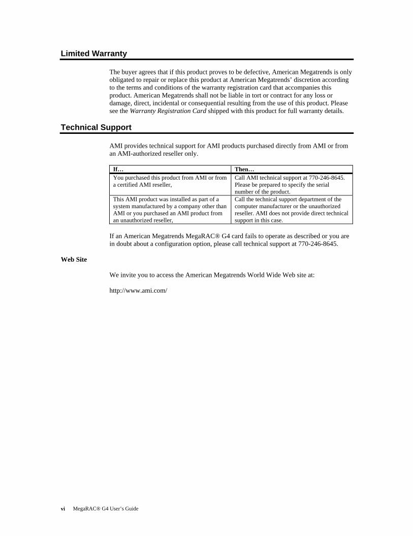
Limited Warranty The buyer agrees that if this product proves to be defective, American Megatrends is only obligated to repair or replace this product at American Megatrends’ discretion according to the terms and conditions of the warranty registration card that accompanies this product. American Megatrends shall not be liable in tort or contract for any loss or damage, direct, incidental or consequential resulting from the use of this product. Please see the Warranty Registration Card shipped with this product for full warranty details.
Technical Support AMI provides technical support for AMI products purchased directly from AMI or from an AMI-authorized reseller only.
If… Then… You purchased this product from AMI or from a certified AMI reseller,
Call AMI technical support at 770-246-8645. Please be prepared to specify the serial number of the product.
This AMI product was installed as part of a system manufactured by a company other than AMI or you purchased an AMI product from an unauthorized reseller,
Call the technical support department of the computer manufacturer or the unauthorized reseller. AMI does not provide direct technical support in this case.
If an American Megatrends MegaRAC® G4 card fails to operate as described or you are in doubt about a configuration option, please call technical support at 770-246-8645.
Web Site We invite you to access the American Megatrends World Wide Web site at: http://www.ami.com/

Preface vii
Disclaimer This manual describes the operation of the American Megatrends MegaRAC® G4 card. Although efforts have been made to assure the accuracy of the information contained here, American Megatrends expressly disclaims liability for any error in this information, and for damages, whether direct, indirect, special, exemplary, consequential or otherwise, that may result from such error, including but not limited to the loss of profits resulting from the use or misuse of the manual or information contained therein (even if American Megatrends has been advised of the possibility of such damages). Any questions or comments regarding this document or its contents should be addressed to American Megatrends at the address shown on the inside of the front cover. American Megatrends provides this publication “as is” without warranty of any kind, either expressed or implied, including, but not limited to, the implied warranties of merchantability or fitness for a specific purpose. Some states do not allow disclaimer of express or implied warranties or the limitation or exclusion of liability for indirect, special, exemplary, incidental or consequential damages in certain transactions; therefore, this statement may not apply to you. Also, you may have other rights which vary from jurisdiction to jurisdiction. This publication could include technical inaccuracies or typographical errors. Changes are periodically made to the information herein; these changes will be incorporated in new editions of the publication. American Megatrends may make improvements and/or revisions in the product(s) and/or the program(s) described in this publication at any time. Requests for technical information about American Megatrends products should be made to your American Megatrends authorized reseller or marketing representative.
MegaRAC® G4 User’s Guide viii
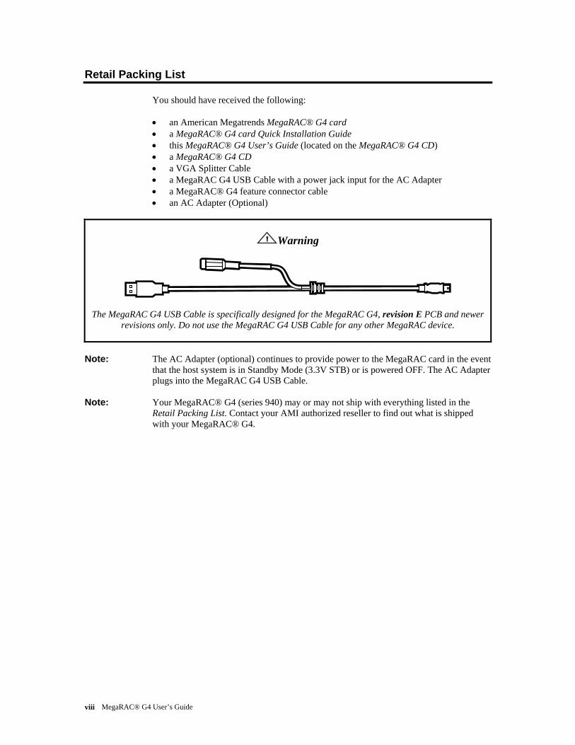
Retail Packing List You should have received the following: • an American Megatrends MegaRAC® G4 card • a MegaRAC® G4 card Quick Installation Guide • this MegaRAC® G4 User’s Guide (located on the MegaRAC® G4 CD) • a MegaRAC® G4 CD • a VGA Splitter Cable • a MegaRAC G4 USB Cable with a power jack input for the AC Adapter • a MegaRAC® G4 feature connector cable • an AC Adapter (Optional)
Warning
The MegaRAC G4 USB Cable is specifically designed for the MegaRAC G4, revision E PCB and newer revisions only. Do not use the MegaRAC G4 USB Cable for any other MegaRAC device.
Note: The AC Adapter (optional) continues to provide power to the MegaRAC card in the event that the host system is in Standby Mode (3.3V STB) or is powered OFF. The AC Adapter plugs into the MegaRAC G4 USB Cable.
Note: Your MegaRAC® G4 (series 940) may or may not ship with everything listed in the Retail Packing List. Contact your AMI authorized reseller to find out what is shipped with your MegaRAC® G4.
Preface ix
FCC Class A Statement This device complies with Part 15 of the FCC Rules. Operation is subject to the following two conditions: (1) this device may not cause harmful interference, and (2) this device must accept any interference received, including interference that may cause undesired operation.
Note: This equipment has been tested and found to comply with the limits for a Class A digital device, pursuant to Part 15 of the FCC Rules. These limits are designed to provide reasonable protection against harmful interference in a residential installation. This equipment generates, uses, and can radiate radio frequency energy and, if not installed and used in accordance with the instructions, may cause harmful interference to radio communications. Operation of this device in a residential area is likely to cause harmful interference in which case the user will be required to correct the interference at his own expense.
If this equipment does cause harmful interference to radio or television reception, which can be determined by turning the equipment off and on, the user is encouraged to try to correct the interference by one or more of the following measures: • Reorient or relocate the receiving antenna. • Increase the separation between the equipment and receiver. • Connect the equipment into an outlet on a circuit different from that to which the
receiver is connected. • Consult the dealer or an experienced radio/TV technician for help.
Warning
Changes or modifications to this device not expressly approved by American Megatrends could void the user’s authority to operate the equipment.
MegaRAC® G4 User’s Guide x
Industry Canada This Class A digital apparatus meets all requirements of the Canadian Interference Causing Equipment Regulations. Operation is subject to the following two conditions; (1) this device digital apparatus meets all requirements of the Canadian Interference Causing Equipment Regulations. Operation is subject to the following two conditions; (1) this device may not cause harmful interference, and (2) this device must accept any interference received, including interference that may cause undesired operation. Cet appareillage numérique de la classe A répond à toutes les exigences de l'interférence canadienne causant des règlements d'équipement. L'opération est sujette aux deux conditions suivantes: (1) ce dispositif peut ne pas causer l'interférence nocive, et (2) ce dispositif doit accepter n'importe quelle interférence reçue, y compris l'interférence qui peut causer l'opération peu désirée.
European Communities
Electromagnetic Compatibility (EMC)-Emissions • Directive 89/336/EEC as amended by • Directive 92/31/EEC • Directive 93/68/EEC [CE Marking] • EN 55024: 1998 + A1:2001 + A2:2003 • EN 55022:1998 (EU)
Power Line Harmonics/Voltage Flicker • European Union-- EN 55022:1998 Radiated & Conducted Emissions Class A • European Union-- EN 61000-3-2/-3 Harmonics & Flicker
Electromagnetic Compatibility-Immunity • European Union-- EN 55024: 1998 + A1:2001 + A2:2003

Chapter One : Introduction 1
Chapter 1 Introduction
Features
Feature Description Key Feature • Remote power control (reset and power cycle) of the managed server
• Text/graphics KVM/IP at any power state • High performance redirection enables remote operating system installation
and software/patch updates • Monitors and manages all environmental sensors • Notifies system administrators with alerts • SNMP trap notification • Onboard customizable web-based interface • Secured web access (https://) • Full IPMI stack on board, acts as BMC
Processor System On Chip (SOC)
• 32-bit running at up to 266 MHz RISC • 16k I-cache • 32k D-cache • 32 MB SDRAM memory • 16 MB flash
Flash • 16-Bit, 16 MB Form Factor • Half Size Standard PCI Card AMI MG9080 KVM Engine
• VGA input for KVM from motherboard VGA or external VGA • Hardware based capture and compression • AMI's "AVICA2a (Analog)" compression engine fully built in to the
hardware • Capable of delivering 30 frames per second full screen/frame updates even
with 16-bit color • Up to 1280 X 1024 resolution support
KVM/IP (console redirection)
• Analog VGA input • AMI's "AVICA2a (Analog)" fourth generation algorithm • High performance up to 30 frames per second • 1280x1024, 1280x960, 1152x864, 1024x768, 800x600, 640x480 • Extremely low network band-width requirement • Auto session timeout for security • Local pass-through output to monitor using splitter cable
Media Redirection • Simultaneous floppy and CD/ DVD redirection • USB 2.0 based CD/DVD redirection with up to 18X CD speed • Support for USB key and USB hard disk • Auto session timeout for security • Virtual presence and front panel redirection • Customizable GUI for the front panel • Provides virtual reality of the remote server management • LCD/LED status display • Floppy, CD/DVD tray control • "At-a-glance" snapshot of the server screen
IPMI 2.0 based management
• Manages the IPMI 2.0 based BMC present in the server • Runs the virtual BMC stack for BMC-less systems and presents as a full
IPMI 2.0 compliant BMC • Customizable sensor management
Event Log & Alerting • Log full and partial full events • Front panel status (LCD/LED) • Sensor readings

MegaRAC® G4 User’s Guide 2
Feature Description SNMP trap • Email (SMTP) notification Web based user interface
• Cross browser support • Customizable GUI • Added security with SSL (HTTPS) • Cross platform support Sophisticated user management • Multiple user permission level • Many user profiles • Web based configuration of the user profiles
Active Directory/LDAP Client support
• Direct LDAP support from the device • Windows Active Directory and Open -LDAP support • Client application to extend the LDAP schema easily
SMASH and CLP support • IPMI 2.0 boot option support • Telnet based SOL • Power control of the server • Fully compliant with the DMTF specification
Multilanguage support • Full Unicode support • Multiple language support for multiple clients simultaneously
Web based configuration • Full configuration using web UI • Personality migration • Fail-safe firmware upgrade
OEM Tools • AMI-PMCP for customizing the sensors for different platforms • Visual WebDev for customizing the GUI
Power Supply • Uses PCI 3.3V Standby Power • Uses PCI 3.3V and 5V Power

Chapter Two : Installing Your MegaRAC® G4 Card 3
Chapter 2 Installing Your MegaRAC® G4 Card
Before You Start
Avoid Electro-Static Discharge (ESD)
Electro-Static Discharge (ESD) can damage the MegaRAC® G4 card and other system components. Keep your MegaRAC® G4 card in its anti-static bag until it is to be installed. Avoid contact with any component or connector on any adapter card, printed circuit board, or memory module. Handle these components by the mounting bracket. Perform all unpacking and installation procedures on a ground-connected anti-static mat. Wear an anti-static wristband grounded at the same point as the anti-static mat. You can also use a sheet of conductive aluminum foil grounded through a one megaohm resistor instead of the anti-static mat. Similarly, a strip of conductive aluminum foil wrapped around the wrist and grounded through a one megaohm resistor serves the same purpose as a wristband.
Hardware Installation Use the following steps to install the MegaRAC® G4 card.
Step Action 1 Unpack the MegaRAC® G4 card (and check jumper settings) 2 Plug in the MegaRAC® G4 card into the host system and attach internal cables 3 Connect external cables 4 Confirm the motherboard’s BIOS settings 5 Initial configuration of the MegaRAC® G4 card 6 Install/Boot to an Operating System
MegaRAC® G4 User’s Guide 4
Step 1 Unpack the MegaRAC® G4 card (and check jumper settings)
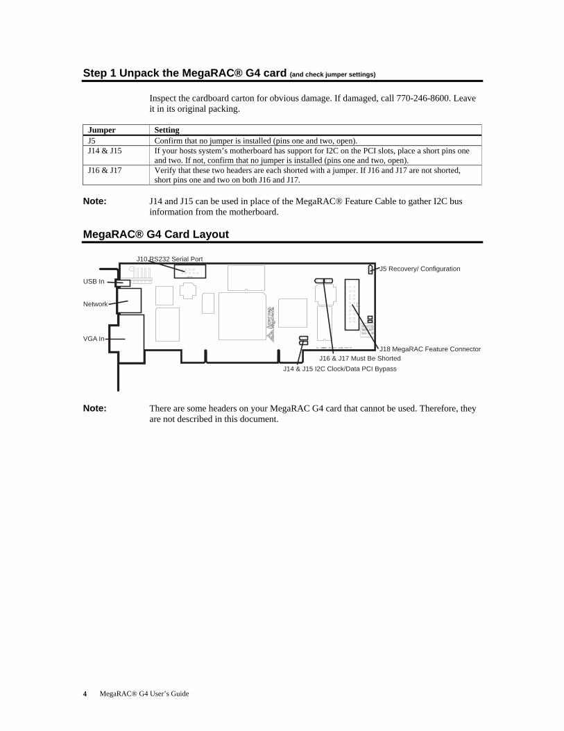
Inspect the cardboard carton for obvious damage. If damaged, call 770-246-8600. Leave it in its original packing.
Jumper Setting J5 Confirm that no jumper is installed (pins one and two, open). J14 & J15 If your hosts system’s motherboard has support for I2C on the PCI slots, place a short pins one
and two. If not, confirm that no jumper is installed (pins one and two, open). J16 & J17 Verify that these two headers are each shorted with a jumper. If J16 and J17 are not shorted,
short pins one and two on both J16 and J17.
Note: J14 and J15 can be used in place of the MegaRAC® Feature Cable to gather I2C bus information from the motherboard.
MegaRAC® G4 Card Layout
USB In
Network
VGA In
J10 RS232 Serial PortJ5 Recovery/ Configuration
J18 MegaRAC Feature ConnectorJ16 & J17 Must Be Shorted
J14 & J15 I2C Clock/Data PCI Bypass
Note: There are some headers on your MegaRAC G4 card that cannot be used. Therefore, they
are not described in this document.

Chapter Two : Installing Your MegaRAC® G4 Card 5
MegaRAC® G4 Card Layout and Connection Guide
USB In
Network
VGA In
J10 RS232 Serial Port
J5 Recovery/ ConfigurationJ18 MegaRAC Feature Connector
J16 & J17 Must Be ShortedJ14 & J15 I2C Clock/Data PCI Bypass
Host System’s Motherboard PCI Slot
VGA Splitter Cable
RJ-45 Network Cable
Plug the AC Adapter here (optional)
To the MegaRAC G4(USB In)To Host System’s USB Port
Power On Cable(Runs between the MegaRAC G4and the Power On Switch located on Front Panel of the Host System)
Power On Cable(Runs between the MegaRAC G4 and the Power On Header located on the Host System’s Motherboard)
Reset Switch Cable(Runs between the MegaRAC G4and the Reset Switch located on Front Panel of the Host System)
Reset Switch Cable(Runs between the MegaRAC G4and the Reset Header located on the Host System’s Motherboard)
I2C Cable(Optional, with Limitations. Runs between the MegaRAC G4 and the IPMB Header located on the Host System’s Motherboard)
To the Monitor (15-pin Female)
To the MegaRAC G4(15-pin Female)
To the Host System’sVGA Port (15-pin Male)
MegaRAC Feature Connector Cable(not to drawn to scale)
Warning
The MegaRAC G4 USB Cable is specifically designed for the MegaRAC G4, revision E PCB and newer revisions only. Do not use the MegaRAC G4 USB Cable for any other MegaRAC device.
Step 2 Plug in the MegaRAC® G4 card into the Host System and Attach Internal Cables
Physically plug in the MegaRAC® G4 card into any available PCI slot inside the host system.
Secure the card into the chassis.Plug the card into a standard PCI slot.Secure the I/O shield of the card to the card mounting on the chassis.
MegaRAC® G4 User’s Guide 6
USB In
Network
VGA In
J10 RS232 Serial Port
J5 Recovery/ ConfigurationJ18 MegaRAC Feature Connector
J16 & J17 Must Be ShortedJ14 & J15 I2C Clock/Data PCI Bypass
Host System’s Motherboard PCI Slot
VGA Splitter Cable
RJ-45 Network Cable
Plug the AC Adapter here (optional)
To the MegaRAC G4(USB In)To Host System’s USB Port
Power On Cable(Runs between the MegaRAC G4and the Power On Switch located on Front Panel of the Host System)
Power On Cable(Runs between the MegaRAC G4 and the Power On Header located on the Host System’s Motherboard)
Reset Switch Cable(Runs between the MegaRAC G4and the Reset Switch located on Front Panel of the Host System)
Reset Switch Cable(Runs between the MegaRAC G4and the Reset Header located on the Host System’s Motherboard)
I2C Cable(Optional, with Limitations. Runs between the MegaRAC G4 and the IPMB Header located on the Host System’s Motherboard)
To the Monitor (15-pin Female)
To the MegaRAC G4(15-pin Female)
To the Host System’sVGA Port (15-pin Male)
MegaRAC Feature Connector Cable(not to drawn to scale)
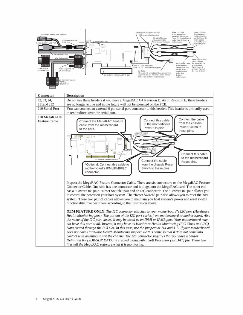
Connector Description J2, J3, J4, J11and J12
Do not use these headers if you have a MegaRAC G4 Revision E. As of Revision E, these headers are no longer active and in the future will not be mounted on the PCB.
J10 Serial Port You can connect an external 9 pin serial port connector to this header. This header is primarily used to text redirect over the serial port.
J18 MegaRAC® Feature Cable
Power On Cable
Reset Switch Cable
I2C Cable
MegaRAC Feature Connector Cable
J18 MegaRAC Feature Connector
Connect the MegaRAC Feature cable from the motherboard to the card.
*Optional. Connect this cable tomotherboard’s IPMI/IPMB/I2Cconnector.
Connect this cable to the motherboard Power On pins.
Connect this cableto the motherboard Reset pins.
Connect the cable from the chassis Power Switch to these pins.
Connect the cable from the chassis Reset Switch to these pins.
Inspect the MegaRAC Feature Connector Cable. There are six connectors on the MegaRAC Feature Connector Cable. One side has one connector and it plugs into the MegaRAC card. The other end has a “Power On” pair, “Reset Switch” pair and an I2C connector. The “Power On” pair allows you to control the power on your host system. The “Reset Switch” pair also allows you to reset the host system. These two pair of cables allows you to maintain you host system’s power and reset switch functionality. Connect them according to the illustration above. OEM FEATURE ONLY: The I2C connector attaches to your motherboard’s I2C port (Hardware Health Monitoring port). The pin-out of the I2C port varies from motherboard to motherboard. Also the name of the I2C port varies. It may be listed as an IPMI or IPMB port. Your motherboard may not have this port at all. Instead, it may have its Hardware Health Monitoring (I2C Clock and I2C) Data routed through the PCI slot. In this case, use the jumpers at J14 and J15. If your motherboard does not have Hardware Health Monitoring support, tie this cable so that it does not come into contact with anything inside the chassis. The I2C connector requires that you have a Sensor Definition Kit (SDK/SDR.DAT) file created along with a Soft Processor (SP.DAT) file. These two files tell the MegaRAC software what it is monitoring.

Chapter Two : Installing Your MegaRAC® G4 Card 7
Step 3 Connect External Cables
Connect the MegaRAC G4USB cable to the card.
(Optional) Connect the Power Adapter to the card.
Connect to the USB Porton the Host System.
Connect to the VGA port on the Host System.
Connect the VGA Splitter Cable to the card.
Connect to the local Monitor.
Connect the Network Cable to the card.
USB In
NetworkVGA In
• Attach the VGA splitter to the MegaRAC® G4 card. Connect the female end to the monitor and the male end to your host system’s VGA port.
• Connect the RJ45 LAN cable from your local network to your MegaRAC® G4 card. • Connect the MegaRAC G4 USB cable from your host system’s USB port to you
MegaRAC® G4 card. • Connect your AC adapter to the MegaRAC G4 USB cable. (The AC adapter is an
optional component.)
Note: The AC Adapter (optional) continues to provide power to the MegaRAC card in the event that the host system is in Standby Mode (3.3V STB) or is powered OFF.
Step 4 Confirm the Motherboard’s BIOS Settings Power on the motherboard and enter the BIOS. Using the following table, confirm that your motherboard’s BIOS settings are correct.
BIOS Section Setting Boot Options> Removable Devices AMI Virtual Floppy or USB Boot
Device Boot Options> ATAPI CDROM AMI Virtual CDROM or USB Boot
Device Advanced> PCIPnP> Configuration> Legacy USB Support Enable
Save the BIOS settings and restart the computer.
Note: Make sure that your motherboard BIOS supports Legacy USB devices, USB Boot or
Boot to USB. Note: On some motherboards and server boards, depress the <CTRL>, <ALT>, and <ESC>
keys simultaneously to enter the BIOS. On others use the <F2> keys. See your server’s documentation for more information on entering the BIOS setup.

MegaRAC® G4 User’s Guide 8
Step 5 Initial Configuration of the MegaRAC® G4 card
The MegaRAC® G4 card is ready to be used at this stage. If you have an AC Adapter attached to the MegaRAC® G4 card’s USB cable, it will be powered on even if your host system is powered OFF. At this point you may wish to do an initial configuration of the MegaRAC® G4 card in order to find its IP Address. You can access the MegaRAC® G4 card from another system via the network. AMI refers to this other system as the client system. To do this, you must know the MegaRAC® G4 card’s IP Address. If you have installed the MegaRAC® G4 card on a network that uses DHCP, you can search the network for the MegaRAC® G4 card. To locate and find out its IP Address, you can run either Intel Device Spy for UPnP Technologies or use the G4ConfigApp Utility located on your CD.
G4ConfigApp The MegaRAC card can be located using the G4ConfigApp utility. Once the IP Address is located or configured, you can use your Internet browser to access the MegaRAC card remotely. The G4ConfigApp utility is a GUI-based program that must be run from the host machine. The host machine is the computer that has the MegaRAC card installed in it. To run the G4ConfigApp program, double left click the G4ConfigApp.exe icon located in the following directories on your MegaRAC™ G4 CD: CDROM\ServerAgent\Windows\ The G4ConfigApp Dialog window will appear. When prompted for the user name and password, use root for the User Name and superuser for the Password. Both are all lower-case characters. Once logged in, you will be able to get the MegaRAC card’s current network information.

Chapter Two : Installing Your MegaRAC® G4 Card 9
Intel Device Spy for UPnP Technologies
If you want to use Device Spy for UPnP Technologies to locate the MegaRAC card follow the steps below: Download Device Spy for UPnP Technologies from the Intel website:
http://www.intel.com/ Do a search for the following phrase:
Intel® Tools for UPnP Technologies The download page changes from time to time, so doing a search will give you the best results. Download the compressed file and uncompress it. The file will have a filename similar to the following:
218892_218892.zip The ZIP file will contain an EXE file that will have a filename similar to the following:
Intel_Tools_4UT_v1768.exe After you run the EXE file, the Device Spy.exe file will become available. Device Spy.exe is the file that contains the Intel Device Spy for UPnP Technologies program. Device Spy: Intel's Universal Control Point (UCP). This tool readily tests "action" invocations and events. Device Spy also traces packets sent to UPnP devices. For more information on how to use Intel Device Spy for UPnP Technologies see the documentation provided with it.
Step Action 1 Download the Intel Device Spy for UPnP Technologies program onto your remote client system.
Run the Intel Device Spy for UPnP Technologies program. The name “MegaRAC®-G4 Device” will display in the tree under UPnP Devices. 3 Select the “MegaRAC®-G4 Device” to view its properties. 4 Click on the IP address located in the “Presentation URL” field to connect to your MegaRAC®
G4 card. 5 When prompted for the user name and password, use root for the User Name and
superuser for the Password. Both are all lower-case characters. 6 Left click the OK button. After you successfully log into your MegaRAC® G4 card, you are
greeted with the Welcome to MegaRAC® G4 card screen.
Note: When you log in using the root user name and password, you have full administrative powers. It is advised that once you log in, you change the root password.
MegaRAC® G4 User’s Guide 10
Setup your Client System’s Internet Browser You must first set up Internet Explorer browser on the client system before you can redirect the host system’s console. Set up Internet Explorer’s Security Settings to allow the downloading of Signed ActiveX controls and also allow it to run Signed ActiveX controls. See the MegaRAC® G4 User’s Guide located on the MegaRAC® G4 CD for more information.
Note: At the time this document was being created, the MegaRAC® ActiveX controls were in the process of being “signed” (by VeriSign®) so that they could be authenticated by Internet browsers. If redirection does not operate properly, you may have to set up Internet Explorer’s Security Settings to allow the downloading of Unsigned ActiveX controls and also allow it to run Unsigned ActiveX controls as well.
Step 6 Install/Boot to an Operating System
At this stage if you already have an operating system loaded on the host system, you can boot to it. While the operating system is booting up, it will detect the MegaRAC® G4 card’s USB devices (that make device redirection possible). The operating system will default to the standard drivers for all devices. If you are running Linux on your host system, it will continue to use default drivers.

Chapter Three : MegaRAC® G4 Card Layout 11
Chapter 3 MegaRAC® G4 Card Layout
USB In
Network
VGA In
J10 RS232 Serial PortJ5 Recovery/ Configuration
J18 MegaRAC Feature ConnectorJ16 & J17 Must Be Shorted
J14 & J15 I2C Clock/Data PCI Bypass
J1 JTAG (Joint Test Action Group) ICE (In-Circuit Emulator) Connector Connector not mounted. This header is used to debug and service the MegaRAC® G4 card. J1 is not described in this document.
J2, J3 and J4 Not Used Do not use these headers if you have a MegaRAC G4 Revision E. As of Revision E, these headers are no longer active and in the future will not be mounted on the PCB.
J5 Recovery/Configuration Mode Jumper
J5 Recovery/ Configuration
Verify that this jumper is not shorted.
The Recovery jumper is used as a means to service the MegaRAC® G4 and is not described in this document.
MegaRAC® G4 User’s Guide 12
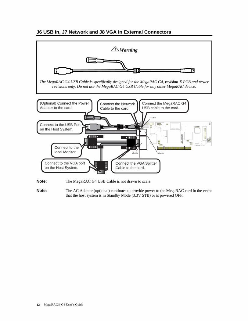
J6 USB In, J7 Network and J8 VGA In External Connectors
Warning
The MegaRAC G4 USB Cable is specifically designed for the MegaRAC G4, revision E PCB and newer revisions only. Do not use the MegaRAC G4 USB Cable for any other MegaRAC device.
Connect the MegaRAC G4USB cable to the card.
(Optional) Connect the Power Adapter to the card.
Connect to the USB Porton the Host System.
Connect to the VGA port on the Host System.
Connect the VGA Splitter Cable to the card.
Connect to the local Monitor.
Connect the Network Cable to the card.
USB In
NetworkVGA In
Note: The MegaRAC G4 USB Cable is not drawn to scale.
Note: The AC Adapter (optional) continues to provide power to the MegaRAC card in the event that the host system is in Standby Mode (3.3V STB) or is powered OFF.
Chapter Three : MegaRAC® G4 Card Layout 13
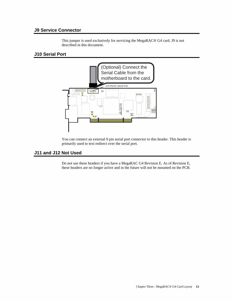
J9 Service Connector This jumper is used exclusively for servicing the MegaRAC® G4 card. J9 is not described in this document.
J10 Serial Port
J10 RS232 Serial Port
(Optional) Connect the Serial Cable from the motherboard to the card.
You can connect an external 9 pin serial port connector to this header. This header is primarily used to text redirect over the serial port.
J11 and J12 Not Used Do not use these headers if you have a MegaRAC G4 Revision E. As of Revision E, these headers are no longer active and in the future will not be mounted on the PCB.
MegaRAC® G4 User’s Guide 14
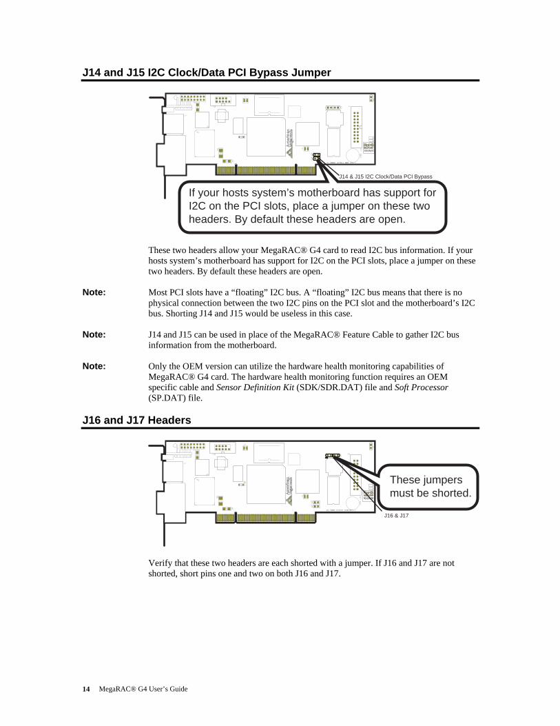
J14 and J15 I2C Clock/Data PCI Bypass Jumper
J14 & J15 I2C Clock/Data PCI Bypass
If your hosts system’s motherboard has support for I2C on the PCI slots, place a jumper on these two headers. By default these headers are open.
These two headers allow your MegaRAC® G4 card to read I2C bus information. If your hosts system’s motherboard has support for I2C on the PCI slots, place a jumper on these two headers. By default these headers are open.
Note: Most PCI slots have a “floating” I2C bus. A “floating” I2C bus means that there is no physical connection between the two I2C pins on the PCI slot and the motherboard’s I2C bus. Shorting J14 and J15 would be useless in this case.
Note: J14 and J15 can be used in place of the MegaRAC® Feature Cable to gather I2C bus information from the motherboard.
Note: Only the OEM version can utilize the hardware health monitoring capabilities of MegaRAC® G4 card. The hardware health monitoring function requires an OEM specific cable and Sensor Definition Kit (SDK/SDR.DAT) file and Soft Processor (SP.DAT) file.
J16 and J17 Headers
J16 & J17
These jumpersmust be shorted.
Verify that these two headers are each shorted with a jumper. If J16 and J17 are not shorted, short pins one and two on both J16 and J17.
Chapter Three : MegaRAC® G4 Card Layout 15
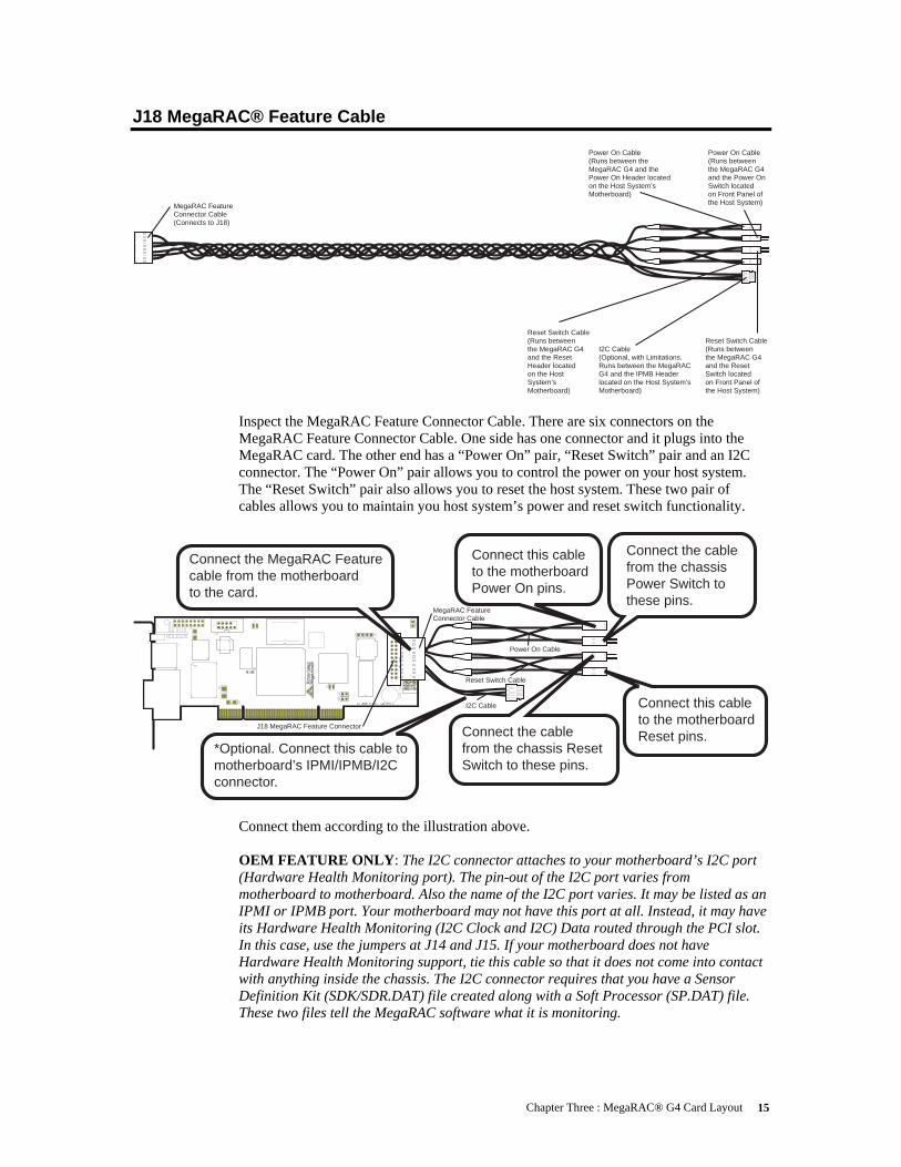
J18 MegaRAC® Feature Cable
Power On Cable(Runs between the MegaRAC G4and the Power On Switch located on Front Panel of the Host System)
Power On Cable(Runs between the MegaRAC G4 and the Power On Header located on the Host System’s Motherboard)
Reset Switch Cable(Runs between the MegaRAC G4and the Reset Switch located on Front Panel of the Host System)
Reset Switch Cable(Runs between the MegaRAC G4and the Reset Header located on the Host System’s Motherboard)
I2C Cable(Optional, with Limitations. Runs between the MegaRAC G4 and the IPMB Headerlocated on the Host System’s Motherboard)
MegaRAC Feature Connector Cable(Connects to J18)
Inspect the MegaRAC Feature Connector Cable. There are six connectors on the MegaRAC Feature Connector Cable. One side has one connector and it plugs into the MegaRAC card. The other end has a “Power On” pair, “Reset Switch” pair and an I2C connector. The “Power On” pair allows you to control the power on your host system. The “Reset Switch” pair also allows you to reset the host system. These two pair of cables allows you to maintain you host system’s power and reset switch functionality.
Power On Cable
Reset Switch Cable
I2C Cable
MegaRAC Feature Connector Cable
J18 MegaRAC Feature Connector
Connect the MegaRAC Feature cable from the motherboard to the card.
*Optional. Connect this cable tomotherboard’s IPMI/IPMB/I2Cconnector.
Connect this cable to the motherboard Power On pins.
Connect this cableto the motherboard Reset pins.
Connect the cable from the chassis Power Switch to these pins.
Connect the cable from the chassis Reset Switch to these pins.
Connect them according to the illustration above. OEM FEATURE ONLY: The I2C connector attaches to your motherboard’s I2C port (Hardware Health Monitoring port). The pin-out of the I2C port varies from motherboard to motherboard. Also the name of the I2C port varies. It may be listed as an IPMI or IPMB port. Your motherboard may not have this port at all. Instead, it may have its Hardware Health Monitoring (I2C Clock and I2C) Data routed through the PCI slot. In this case, use the jumpers at J14 and J15. If your motherboard does not have Hardware Health Monitoring support, tie this cable so that it does not come into contact with anything inside the chassis. The I2C connector requires that you have a Sensor Definition Kit (SDK/SDR.DAT) file created along with a Soft Processor (SP.DAT) file. These two files tell the MegaRAC software what it is monitoring.
MegaRAC® G4 User’s Guide 16
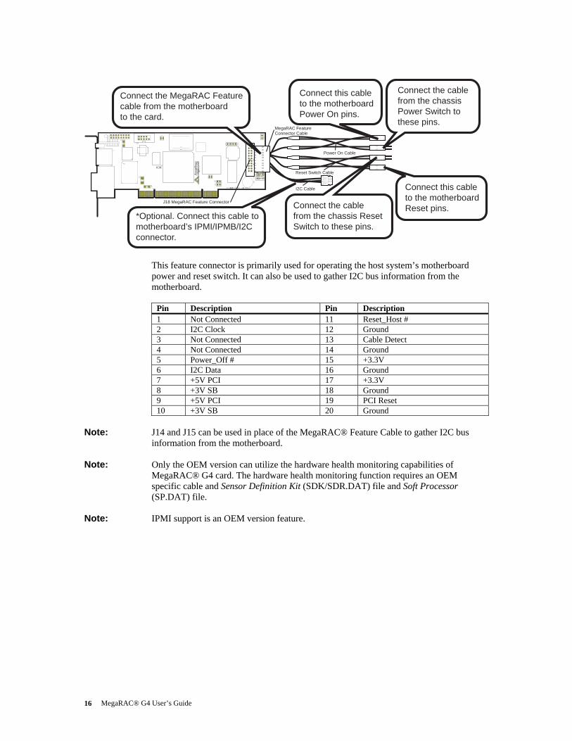
Power On Cable
Reset Switch Cable
I2C Cable
MegaRAC Feature Connector Cable
J18 MegaRAC Feature Connector
Connect the MegaRAC Feature cable from the motherboard to the card.
*Optional. Connect this cable tomotherboard’s IPMI/IPMB/I2Cconnector.
Connect this cable to the motherboard Power On pins.
Connect this cableto the motherboard Reset pins.
Connect the cable from the chassis Power Switch to these pins.
Connect the cable from the chassis Reset Switch to these pins.
This feature connector is primarily used for operating the host system’s motherboard power and reset switch. It can also be used to gather I2C bus information from the motherboard.
Pin Description Pin Description 1 Not Connected 11 Reset_Host # 2 I2C Clock 12 Ground 3 Not Connected 13 Cable Detect 4 Not Connected 14 Ground 5 Power_Off # 15 +3.3V 6 I2C Data 16 Ground 7 +5V PCI 17 +3.3V 8 +3V SB 18 Ground 9 +5V PCI 19 PCI Reset 10 +3V SB 20 Ground
Note: J14 and J15 can be used in place of the MegaRAC® Feature Cable to gather I2C bus
information from the motherboard.
Note: Only the OEM version can utilize the hardware health monitoring capabilities of MegaRAC® G4 card. The hardware health monitoring function requires an OEM specific cable and Sensor Definition Kit (SDK/SDR.DAT) file and Soft Processor (SP.DAT) file.
Note: IPMI support is an OEM version feature.
Chapter Three : MegaRAC® G4 Card Layout 17
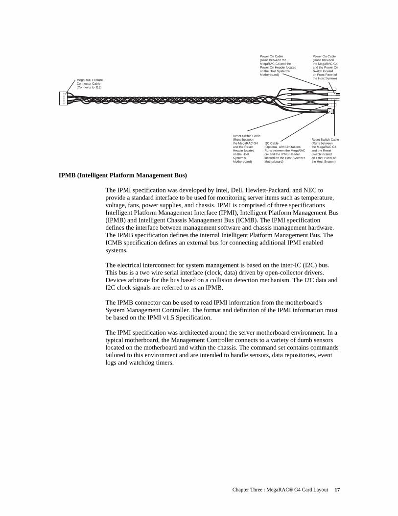
Power On Cable(Runs between the MegaRAC G4and the Power On Switch located on Front Panel of the Host System)
Power On Cable(Runs between the MegaRAC G4 and the Power On Header located on the Host System’s Motherboard)
Reset Switch Cable(Runs between the MegaRAC G4and the Reset Switch located on Front Panel of the Host System)
Reset Switch Cable(Runs between the MegaRAC G4and the Reset Header located on the Host System’s Motherboard)
I2C Cable(Optional, with Limitations. Runs between the MegaRAC G4 and the IPMB Headerlocated on the Host System’s Motherboard)
MegaRAC Feature Connector Cable(Connects to J18)
IPMB (Intelligent Platform Management Bus) The IPMI specification was developed by Intel, Dell, Hewlett-Packard, and NEC to provide a standard interface to be used for monitoring server items such as temperature, voltage, fans, power supplies, and chassis. IPMI is comprised of three specifications Intelligent Platform Management Interface (IPMI), Intelligent Platform Management Bus (IPMB) and Intelligent Chassis Management Bus (ICMB). The IPMI specification defines the interface between management software and chassis management hardware. The IPMB specification defines the internal Intelligent Platform Management Bus. The ICMB specification defines an external bus for connecting additional IPMI enabled systems. The electrical interconnect for system management is based on the inter-IC (I2C) bus. This bus is a two wire serial interface (clock, data) driven by open-collector drivers. Devices arbitrate for the bus based on a collision detection mechanism. The I2C data and I2C clock signals are referred to as an IPMB. The IPMB connector can be used to read IPMI information from the motherboard's System Management Controller. The format and definition of the IPMI information must be based on the IPMI v1.5 Specification. The IPMI specification was architected around the server motherboard environment. In a typical motherboard, the Management Controller connects to a variety of dumb sensors located on the motherboard and within the chassis. The command set contains commands tailored to this environment and are intended to handle sensors, data repositories, event logs and watchdog timers.

MegaRAC® G4 User’s Guide 18
Chapter Four : Using Your MegaRAC® G4 19
Chapter 4 Using Your MegaRAC® G4
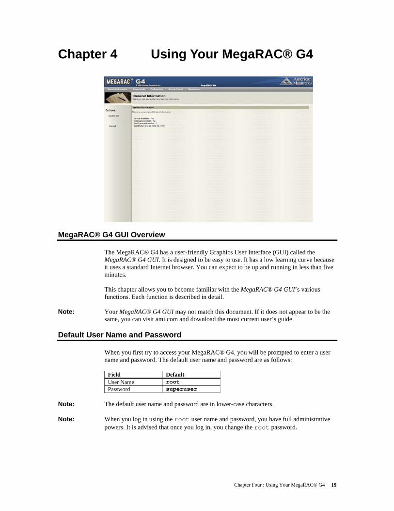
MegaRAC® G4 GUI Overview The MegaRAC® G4 has a user-friendly Graphics User Interface (GUI) called the MegaRAC® G4 GUI. It is designed to be easy to use. It has a low learning curve because it uses a standard Internet browser. You can expect to be up and running in less than five minutes. This chapter allows you to become familiar with the MegaRAC® G4 GUI’s various functions. Each function is described in detail.
Note: Your MegaRAC® G4 GUI may not match this document. If it does not appear to be the same, you can visit ami.com and download the most current user’s guide.
Default User Name and Password When you first try to access your MegaRAC® G4, you will be prompted to enter a user name and password. The default user name and password are as follows:
Field Default User Name root Password superuser
Note: The default user name and password are in lower-case characters.
Note: When you log in using the root user name and password, you have full administrative
powers. It is advised that once you log in, you change the root password.
MegaRAC® G4 User’s Guide 20
MegaRAC® G4 GUI Explained After you successfully log into your MegaRAC® G4, you are greeted with the MegaRAC® G4 GUI.
Menu Bar There is a menu bar located at the top of the MegaRAC® G4 GUI. It lists the following groups: • General Information Group • Server Health Group • Configuration Group • Remote Control Group • Maintenance Group
General Information Group This group of pages allows you to view system information.
System Information This page displays information about the firmware and device availability.
Server Health Group This group of pages allows you to view the sensor readings, system event logs and allows configuring of the health ‘Monitoring Mode’.

Chapter Four : Using Your MegaRAC® G4 21
Sensor Monitoring Options This page allows you to select sensor monitoring options. Sensors can be monitored external baseboard management controller (BMC) connected to the PMB bus or you can directly monitor sensors on the I2C bus.
Item Description Monitoring Options
You can select how you want to monitor the sensors. Direct Monitoring of sensors on the I2C bus (needs PMCP files) Monitoring via External BMC (needs IPMB connection)
External BMC Slave Address
If being monitored by an external BMC, you will need to provide the slave address so that the MegaRAC® G4 card will be able to read data from the onboard BMC on the motherboard/ server board. 0x20 is the address most commonly used.
PMCP monitoring file (sp.bin)
Select the Soft Processor (SP) File with the BIN file extension.
Sensor definitions file (sdr.dat)
Select the SDR File with the BIN file extension.
Upload new file (if one already exists)
Select this option if the SDR and Soft Processor (SP) File are already loaded on the card and you want to have it replaced with the new file.
Browse Button Use this button to look for the SDR and Soft Processor (SP) File. Save Button Use this button to save your settings.

MegaRAC® G4 User’s Guide 22
Sensor Reading This page displays all sensor readings and thresholds from the system.
Item Description Select a sensor type category
You can select a specific category of sensors that you may want to view or all the sensors. All Sensors Temperature Sensors Voltage Sensors Fan Sensors
Sensor Readings
This field displays the individual sensor’s name, reading and the current status of the sensor.
Refresh Button Use this button to refresh the sensor readings view. Show Thresholds Button
Clicking ‘Show Thresholds’ button expands the sensor reading table and also show the various threshold settings for every sensor. Name Status Reading Low NR Low CT Low NC High NC High CT High NR
Chapter Four : Using Your MegaRAC® G4 23
Event Log On this page there is a table of the events from the system's event log.
Item Description Select an event log category
Select one of the following event categories: • Sensor-Specific Events • BIOS Generated Events • System Management Software Events
Event Log You can obtain the following information for each event: • Event ID • Time Stamp • Sensor Name • Sensor Type • Description
Clear Event Log Button
Left click the Event Log menu item to view and clear the event logs.
Configuration Group
This group of pages allows you to access various configuration settings.
Network Settings This page allows you to view and modify the network settings on this page. Select whether to obtain an IP address automatically or manually configure one.
Item Description MAC Address This field displays the MAC address of the MegaRAC® G4 card. Obtain an IP address automatically (use DHCP)
This option allows the MegaRAC® G4’s IP to be configured by a DHCP server (dynamically).
Use the following IP address
This option allows you to configure the MegaRAC® G4’s IP address with a static IP. The IP Address, Subnet Mask, and Gateway fields will become editable when this option is selected.
IP Address This field allows you to set the MegaRAC® G4’s IP address. Subnet Mask This field allows you to set the Subnet Mask The MegaRAC® G4 resides on. Default Gateway
This field allows you to set the MegaRAC® G4’s Gateway access address.
Save Button Use this button to save your settings.
MegaRAC® G4 User’s Guide 24
User List This page allows you to view the current list of user slots for the server. If you would like to delete or modify a user, select their name in the list and press Delete User or Modify User. To add a new user, select an un-configured slot and press Add User.
Item Description UserID This field displays the ID number used in association with the User Name. User Name This field displays a list of all users who are able to access this MegaRAC®
G4. Note: The default administrator is root. It is prudent for you to change the root password.
Network Privilege
This field displays the network rights associated with the account.
Add User Button
Use this button to add a new user. You must select an open field first.
Modify User Button
Use this button to modify an existing user. You must select a user first.
Delete User Button
Use this button to delete an existing user. You must select a user first.
Chapter Four : Using Your MegaRAC® G4 25
Add New User
This page allows you to enter the requested information for the new user. You can add a new user by entering the information for the new user and by selecting the Add button. Press Cancel to return to the user list.
Note: Only user accounts with administrative rights are allowed to add, edit, and remove users. Non-administrator users can only change their own password. If a new user is given administrative privileges, permissions are automatically granted for all interfaces.
Item Description User Name Enter a user name in the Username field. Your user name must be at least
four characters long and no more than 32 characters long. User names are case-sensitive and must start with an alphabetical character.
Password Enter a password in the Password field. Your password must be at least eight characters long. Note: The password must be a minimum of eight characters and a
maximum of 32 characters. Use a mixture of alphanumeric and special characters for better security. The password is case-sensitive.
Confirm Password
Confirm your password by entering your password again in the Confirm Password field.
Network Privileges
Assign network permissions and access rights. • Administrator • Operator • No Access
Add Button Use this button to add the new user. Cancel Button Use this button to cancel this action.

MegaRAC® G4 User’s Guide 26
Modify User
Enter the new information for the user below and press Modify. Press Cancel to return to the user list.
Item Description User Name This field contains the user name being modified. This field cannot be
modified. Change Password
Place a check in this box to change the password.
Password Enter the new password in the Password field. Your password must be at least eight characters long. Note: The password must be a minimum of eight characters and a
maximum of 32 characters. Use a mixture of alphanumeric and special characters for better security. The password is case-sensitive.
Confirm Password
Confirm your password by entering your password again in the Confirm Password field.
Network Privileges
Assign network permissions and access rights. • Administrator • Operator • User • Callback • No Access
Modify Button Use this button to update the user account. Cancel Button Use this button to cancel this action.
Delete User
If you would like to delete a user, select their name in the list and select the Delete User button.
Chapter Four : Using Your MegaRAC® G4 27
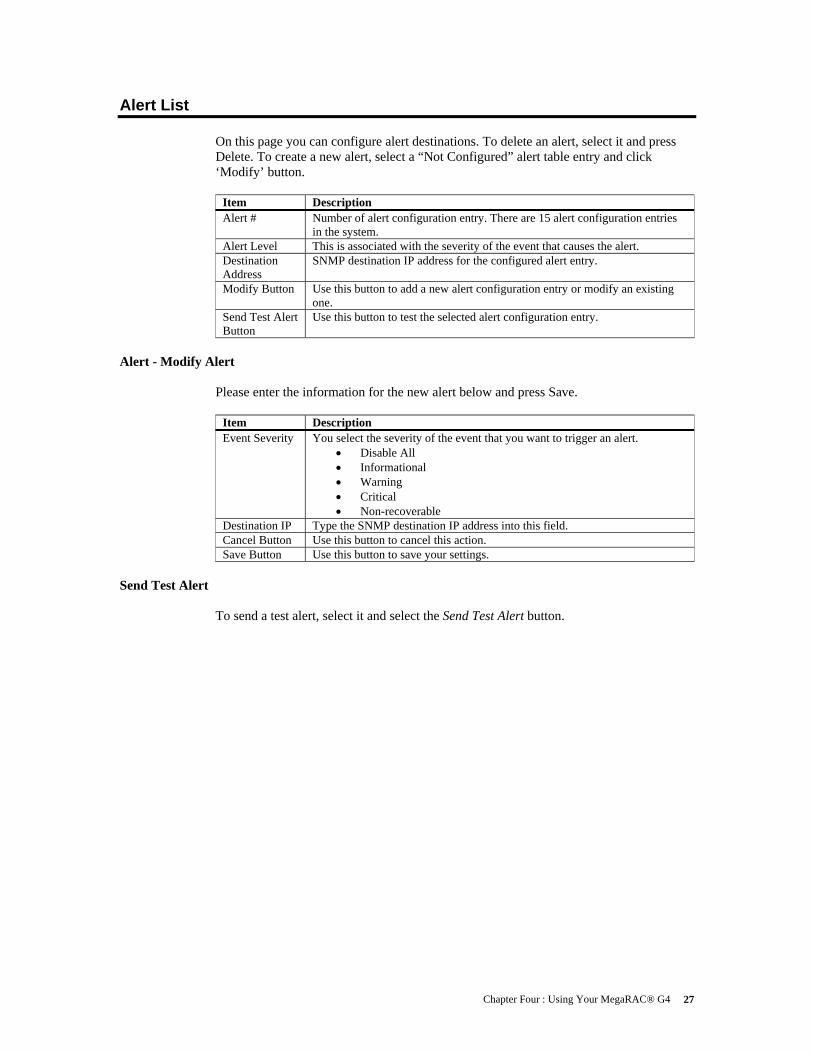
Alert List On this page you can configure alert destinations. To delete an alert, select it and press Delete. To create a new alert, select a “Not Configured” alert table entry and click ‘Modify’ button.
Item Description Alert # Number of alert configuration entry. There are 15 alert configuration entries
in the system. Alert Level This is associated with the severity of the event that causes the alert. Destination Address
SNMP destination IP address for the configured alert entry.
Modify Button Use this button to add a new alert configuration entry or modify an existing one.
Send Test Alert Button
Use this button to test the selected alert configuration entry.
Alert - Modify Alert
Please enter the information for the new alert below and press Save.
Item Description Event Severity You select the severity of the event that you want to trigger an alert.
• Disable All • Informational • Warning • Critical • Non-recoverable
Destination IP Type the SNMP destination IP address into this field. Cancel Button Use this button to cancel this action. Save Button Use this button to save your settings.
Send Test Alert
To send a test alert, select it and select the Send Test Alert button.
MegaRAC® G4 User’s Guide 28
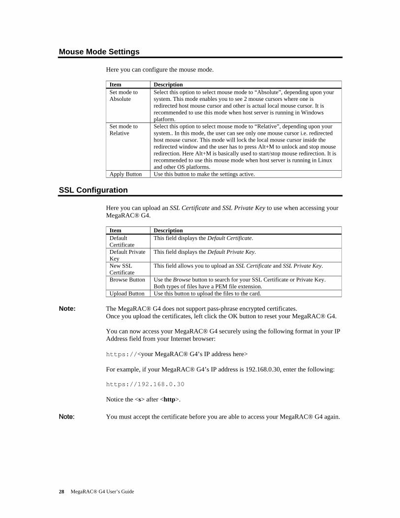
Mouse Mode Settings Here you can configure the mouse mode.
Item Description Set mode to Absolute
Select this option to select mouse mode to “Absolute”, depending upon your system. This mode enables you to see 2 mouse cursors where one is redirected host mouse cursor and other is actual local mouse cursor. It is recommended to use this mode when host server is running in Windows platform.
Set mode to Relative
Select this option to select mouse mode to “Relative”, depending upon your system.. In this mode, the user can see only one mouse cursor i.e. redirected host mouse cursor. This mode will lock the local mouse cursor inside the redirected window and the user has to press Alt+M to unlock and stop mouse redirection. Here Alt+M is basically used to start/stop mouse redirection. It is recommended to use this mouse mode when host server is running in Linux and other OS platforms.
Apply Button Use this button to make the settings active.
SSL Configuration Here you can upload an SSL Certificate and SSL Private Key to use when accessing your MegaRAC® G4.
Item Description Default Certificate
This field displays the Default Certificate.
Default Private Key
This field displays the Default Private Key.
New SSL Certificate
This field allows you to upload an SSL Certificate and SSL Private Key.
Browse Button Use the Browse button to search for your SSL Certificate or Private Key. Both types of files have a PEM file extension.
Upload Button Use this button to upload the files to the card.
Note: The MegaRAC® G4 does not support pass-phrase encrypted certificates. Once you upload the certificates, left click the OK button to reset your MegaRAC® G4. You can now access your MegaRAC® G4 securely using the following format in your IP Address field from your Internet browser: https://<your MegaRAC® G4’s IP address here> For example, if your MegaRAC® G4’s IP address is 192.168.0.30, enter the following: https://192.168.0.30 Notice the <s> after <http>.
Note: You must accept the certificate before you are able to access your MegaRAC® G4 again.

Chapter Four : Using Your MegaRAC® G4 29
LDAP Settings This page allows you to access the Lightweight Directory Access Protocol (LDAP) Server and authentication information and LDAP Settings information. LDAP is an Internet protocol that MegaRAC® card can use to authenticate users. If you have an LDAP server configured on your network, you can use it as an easy way to add, manage and authenticate MegaRAC® card users. It does this by passing login requests to your LDAP Server. This means that there is no need to define an additional authentication mechanism when using the MegaRAC card. Since your existing LDAP Server keeps authentication centralized, you will always know who is accessing network resources and can easily define user/group-based policies to control access. Use the following fields to authenticate and access the LDAP server.
Item Description Enable LDAP Authentication
Check this box to enable LDAP authentication through an LDAP server.
Port Enter the port address of your LDAP server. A common port used by LDAP is port 389.
IP Address Type in the IP address of your LDAP server. Bind Password The Bind Password specifies the password for the MegaRAC card to use
when binding to your LDAP server. Bind DN Type the Bind DN name in the Bind Distinguished Name field. The Bind DN
is required if anonymous binds are not allowed on your LDAP server. Searchbase An LDAP directory requires an RFC 2247–compliant distinguished name, or
search base, to perform an LDAP search. Type in your search base name here.

MegaRAC® G4 User’s Guide 30
Remote Control Group This group of pages allows you to manage the remote console and power status of the server.
Launch Redirection This page allows you to launch console redirection and to manage the remote server. Select the desired viewer that you wish to use to start redirection. Click on the appropriate button to launch the remote console.
Two console viewers are available for redirection support.
1. ActiveX Console (Only on a windows platform with Internet Explorer) 2. Java Console (Recommended on all platforms)
Remote Console Shortcut Key Combinations The most powerful feature of your MegaRAC® G4 is the ability to redirect the host system’s console. To redirect the host system’s console is the ability to manage your host system as if it were physically in front of you, when it is not. The following table is a list of basic keystrokes and their functions:
Keystroke Description <ATL> + <S> Start Console Redirection <ATL> + <T> Stop Console Redirection <ATL> + <R> Restart Console Redirection <ATL> + <F> Toggle Full Screen Mode <ATL> + <M> Synchronize Mouse <ATL> + <A> Hold/Unhold Right <ATL> Key <ATL> + <B> Hold/Unhold Left <ATL> Key <ATL> + <L> Hold/Unhold Right <CTRL> Key <ATL> + <N> Hold/Unhold Left <CTRL> Key <ATL> + <D> Generate <CTRL>, <ATL>, + <DEL> <ATL> + <E> Start CD-ROM Drive Redirection
Note: Occasionally, when invoking the <ALT> + <E> keys, the screen does not refresh and
will appear to be blank. You can hit any key on your keyboard or move the mouse to refresh the screen.
Chapter Four : Using Your MegaRAC® G4 31
Console Redirection Window
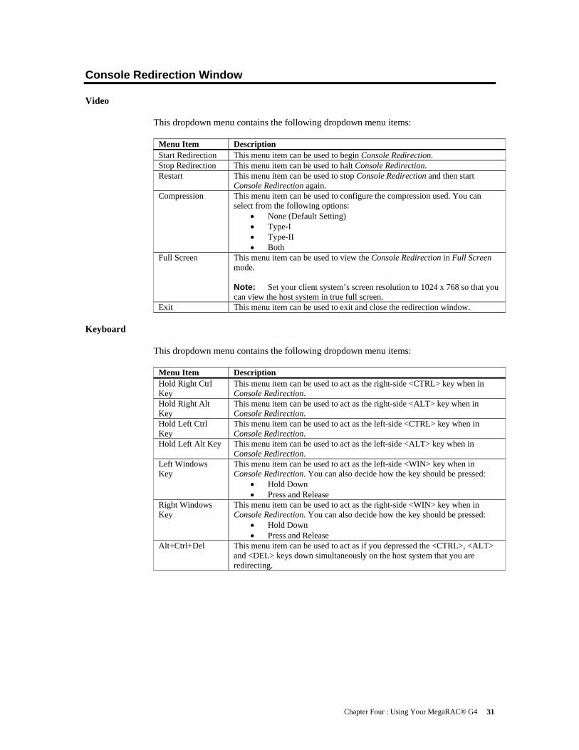
Video This dropdown menu contains the following dropdown menu items:
Menu Item Description Start Redirection This menu item can be used to begin Console Redirection. Stop Redirection This menu item can be used to halt Console Redirection. Restart This menu item can be used to stop Console Redirection and then start
Console Redirection again. Compression This menu item can be used to configure the compression used. You can
select from the following options: • None (Default Setting) • Type-I • Type-II • Both
Full Screen This menu item can be used to view the Console Redirection in Full Screen mode. Note: Set your client system’s screen resolution to 1024 x 768 so that you can view the host system in true full screen.
Exit This menu item can be used to exit and close the redirection window.
Keyboard This dropdown menu contains the following dropdown menu items:
Menu Item Description Hold Right Ctrl Key
This menu item can be used to act as the right-side <CTRL> key when in Console Redirection.
Hold Right Alt Key
This menu item can be used to act as the right-side <ALT> key when in Console Redirection.
Hold Left Ctrl Key
This menu item can be used to act as the left-side <CTRL> key when in Console Redirection.
Hold Left Alt Key This menu item can be used to act as the left-side <ALT> key when in Console Redirection.
Left Windows Key
This menu item can be used to act as the left-side <WIN> key when in Console Redirection. You can also decide how the key should be pressed:
• Hold Down • Press and Release
Right Windows Key
This menu item can be used to act as the right-side <WIN> key when in Console Redirection. You can also decide how the key should be pressed:
• Hold Down • Press and Release
Alt+Ctrl+Del This menu item can be used to act as if you depressed the <CTRL>, <ALT> and <DEL> keys down simultaneously on the host system that you are redirecting.

MegaRAC® G4 User’s Guide 32
Mouse
This dropdown menu contains the following dropdown menu item:
Menu Item Description Sync Cursor This menu item can be used to synchronize or unsynchronize the mouse
cursor.
Options This dropdown menu contains the following dropdown menu items:
Menu Item Description Bandwidth The Bandwidth Usage option allows you to adjust the bandwidth. You can
select one of the following: • 256 Kbps • 512 Kbps • 1 Mbps • 10 Mbps • 100 Mbps (Default Setting)
Quality This option allows you to configure the video quality. Depending on the bandwidth selected, you can adjust the speed/quality level. The level can be from 1 through 5, 1 being the maximum speed for given bandwidth and 5 being the maximum quality for given bandwidth. The relation between speed and quality is that more speed tries to reduce the data over network and thus reducing quality and vice versa.
Video Settings The Video Performance Parameters allows you to enhance the frame rate of your remote console session. Red Gain slider This slider allows you to increase or decrease the
amount of red. Green Gain slider This slider allows you to increase or decrease the
amount of green. Blue Gain slider This slider allows you to increase or decrease the
amount of blue. Horizontal This allows you to modify the horizontal
position of the screen. Vertical Position This allows you to modify the vertical position
of the screen. Set Default Gains button This button allows you to reset the color gains to
the default levels. Auto Calibrate button This button allows the card to automatically set
the color gains and noise thresholds. KB/Mouse Encryption
This option allows you to encrypt keyboard inputs and mouse movements sent between the connections.

Chapter Four : Using Your MegaRAC® G4 33
Device This dropdown menu contains the following dropdown menu items:
Menu Item Description CDROM This menu item can be used to start or stop the redirection of the CD-ROM
drive. You can redirect from an image of a CD or from a physical CD-ROM drive.
Floppy This menu item can be used to start or stop the redirection of the floppy drive. You can redirect from an image of a disk or from a physical floppy drive. Note: Floppy Redirection is not an available feature on all versions of
the MegaRAC® G4 cards.
Help This dropdown menu contains the following dropdown menu item:
Menu Item Description About AVCView Displays the copyright and version information.
Power Status and Control
This page allows you to view and control the power of your host system. Select one of the options listed in the following table to execute on your host system. You will be asked to confirm your choice. Upon confirmation, the command will be executed and you will be informed of the status.
Item Description Select Power Control Mechanism Dropdown Menu
Select the power control mechanism option. You can select one of the following types:
• Using External IPMI BMC via IPMB bus • Using Power Control Feature Connector
Reset Server Select this option to reset the host system. Power Off Server - Immediate
Select this option to power down the host system immediately.
Power Off Server - Orderly Shutdown
Select this option to power down the host system gracefully.
Power On Server Select this option to power up the host system. Power Cycle Server
Select this option to power cycle the host system.
Perform Action Button
Select this button to execute the option selected.
Maintenance Group
This group of pages allows you to do maintenance tasks on the device.

MegaRAC® G4 User’s Guide 34
Firmware Update
Warning
DO NOT CLOSE THE WINDOW USING THE CLOSE BUTTON (X) ON THE TITLE BAR WHEN THE MEGARAC® IS IN UPDATE MODE. USE THE CANCEL
BUTTON ONLY!
Note: The firmware upgrade process is a crucial operation. Make sure that the chances of a power or connectivity loss are minimal when performing this operation.
Note: Once you enter into Update Mode and choose to cancel the firmware flash operation, the MegaRAC® card must be reset. This means that you must close the Internet browser and log back onto the MegaRAC® card before you can perform any other types of operations. You can update the device's firmware here. Select the Enter Update Mode button to put the device in a special mode that allows firmware update. You can now follow the instructions presented in the subsequent pages to successfully update the card’s firmware. The device will reset if update is canceled.
Item Description Enter Update Mode Button
Select the Enter Update Mode button to put the device in a special mode that allows firmware update. Follow the instructions listed on the update wizard. The device will reset if update is canceled.
Logging Out
To log out, simply click on the Log Out link.

Appendix A : Troubleshooting 35
Appendix A Troubleshooting
BMC Not Responding
Problem The BMC does not respond.
Symptom You cannot power off, power on, or power cycle the host system. You cannot obtain Host System health information.
Solution Make sure that in IPMI configuration "Use server's onboard BMC to access health information" is checked. Confirm that the BMC I2C address needs to be set to 0X20. When the BMC is in locked state the user cannot get the sensor information. In order to make the BMC come out of that state the system needs to be rebooted. The BMC's I2C address should never be set to 0x21 – that is not a valid address. 0x20 is the correct address for almost all BMCs. If it is not, the BMC or motherboard provider must supply the correct one. Many BMCs feature a reset button that can be used to reset the BMC only. That button can be used to reset the BMC. If using a BMC without a BMC reset button, the system must be powered off and the power cable(s) unplugged. Some BMCs will run on system standby power, and stay on even though the system is in an off state.

MegaRAC® G4 User’s Guide 36
Cannot Power On the Host System Remotely
Problem Cannot remotely power on, power off, or power cycle the host system.
Symptom When connected to the MegaRAC® G4 remotely (using the GUI), power on, power off, and power cycle does not work properly.
Solution The user should make sure that the feature cable is connected properly from the G4 card and the host system’s main board and chassis. The wall AC adapter must be connected to the MegaRAC® G4 card in order for power control options to operate properly.

Appendix B : Serial Over LAN 37
Appendix B Serial Over LAN
Hardware Setup You can use an external serial port connector and null modem cable to setup the MegaRAC® G4 to perform Serial over LAN operations. To do this, you must have an external 9-pin serial port connector and cable plugged into the MegaRAC® G4 card’s serial port connector at J10. Once the external 9-pin serial port connector is installed and secured to the chassis, attach the null modem cable.
BIOS After you have established a physical connection from your host system’s serial port to you MegaRAC® G4 card, you must enable Remote Access in your AMIBIOS.
Step Description 1 From the host system’s terminal, enter the AMIBIOS setup. 2 Confirm that your Onboard Serial Port you are using is enabled. 3 Enter the Remote Access Configurations menu. 4 Set the Remote Access setting to [Serial]. 5 Set the Serial Port Number to [COM1] or [COM2] depending on the serial
(COM) port you are using. 6 Set the Serial Port Mode baud rate you desire. By default, it is set to [19200
8,n,1]. 7 If available, you can set the Post-Boot Support option. When enabled, the
MegaRAC® G4 attempts to output the DOS screens or the initial windows text screens. This is really handy when you want to see the OS Boot Menu.
8 Save and Exit the BIOS.
Connecting using Hyper Terminal The best way to telnet into the MegaRAC® card is through Hyper Terminal. It is assumed that you know how to use Hyper Terminal. Usage of Hyper Terminal is therefore not documented here.
Remember What Connect using the Serial Port (either COM1 or COM2) Bits per second set to 19200 Data bits set to 8 Parity set to None Stop bits set to 1 Flow control set to None
Note: To invoke the <DEL> key, map the <DEL> key to the <BACKSPACE> key in the Hyper
Terminal Properties window.

MegaRAC® G4 User’s Guide 38
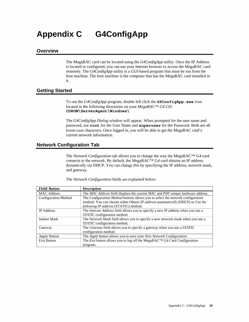
Appendix C : G4ConfigApp 39
Appendix C G4ConfigApp
Overview The MegaRAC card can be located using the G4ConfigApp utility. Once the IP Address is located or configured, you can use your Internet browser to access the MegaRAC card remotely. The G4ConfigApp utility is a GUI-based program that must be run from the host machine. The host machine is the computer that has the MegaRAC card installed in it.
Getting Started To run the G4ConfigApp program, double left click the G4ConfigApp.exe icon located in the following directories on your MegaRAC™ G4 CD: CDROM\ServerAgent\Windows\ The G4ConfigApp Dialog window will appear. When prompted for the user name and password, use root for the User Name and superuser for the Password. Both are all lower-case characters. Once logged in, you will be able to get the MegaRAC card’s current network information.
Network Configuration Tab The Network Configuration tab allows you to change the way the MegaRAC™ G4 card connects to the network. By default, the MegaRAC™ G4 card obtains an IP address dynamically via DHCP. You can change this by specifying the IP address, network mask, and gateway. The Network Configuration fields are explained below:
Field/ Button Description MAC Address The MAC Address field displays the current MAC and PHY unique hardware address. Configuration Method The Configuration Method buttons allows you to select the network configuration
method. You can choose either Obtain IP address automatically (DHCP) or Use the following IP address (STATIC) method.
IP Address The Internet Address field allows you to specify a new IP address when you use a STATIC configuration method.
Subnet Mask The Network Mask field allows you to specify a new network mask when you use a STATIC configuration method.
Gateway The Gateway field allows you to specify a gateway when you use a STATIC configuration method.
Apply Button The Apply button allows you to save your New Network Configuration. Exit Button The Exit button allows you to log off the MegaRAC™ G4 Card Configuration
program.

MegaRAC® G4 User’s Guide 40
User Manager Tab The User Manager tab allows you to manage the MegaRAC™ G4 card’s users. Here you can add, delete, and modify users.
Field/ Button Description Add Button The Add button allows you to add a new administrator to the MegaRAC™ G4
card’s user list. The user name must be no more than eight characters long. Remove Button The Remove button allows you to delete an existing administrator from the user list.
Simply highlight the account name that you want to remove and left click the Remove button.
Properties Button The Properties button allows you to view and edit an existing administrator’s record.
Exit Button The Exit button allows you to log off the MegaRAC™ G4 Card Configuration program.
Adding a User
The Add User fields are explained below:
Field/ Button Description User Name You can enter the name of this account in this field. Description You can enter a short description for this account. Password You can use this field to enter the account password.
Note: The password must be a minimum of eight characters and a maximum of
32 characters. Use a mixture of alphanumeric and special characters for better security.
Confirm Password You must reenter the password. The Confirm Password field allows you to reenter the user’s password.
Permissions You can select the permission level for this account.
User Properties
Field/ Button Description User Name The selected MegaRAC™ G4 card user is displayed in this field. It cannot be
changed. Description You can view and modify the short description for this account. Change Password Left click this box if you want to change the user’s password. New Password After you check the Change Password box, you can use this field to enter the new
password. Note: The password must be a minimum of eight characters and a maximum of
32 characters. Use a mixture of alphanumeric and special characters for better security.
Confirm Password You must reenter the new password. The Confirm Password field allows you to reenter the user’s new password.
Permissions You can view and modify the permission level for this account.

Appendix D: SMASH Command Line Utility 41
Appendix D SMASH Command Line Utility
Overview This appendix explains how to use SMASH. You can access SMASH through a Telnet client. This is useful when you do not have a DHCP server on your network and need to statically assign the IP address to the MegaRAC®.
Prerequisites You need the following before you begin: • a system with a Telnet client (such as HyperTerminal) • a serial cable • your network’s properties (Subnet and Gateway) • username and password to access the MegaRAC® (if different from the default
settings)
Hardware Setup You can use an external serial port connector and null modem cable to setup the MegaRAC® G4 to perform Serial over LAN operations. To do this, you must have an external 9-pin serial port connector and cable plugged into the MegaRAC® G4 card’s serial port connector at J10. Once the external 9-pin serial port connector is installed and secured to the chassis, attach the null modem cable.
BIOS After you have established a physical connection from your host system’s serial port to you MegaRAC® G4 card, you must enable Remote Access in your AMIBIOS.
Step Description 1 From the host system’s terminal, enter the AMIBIOS setup. 2 Confirm that your Onboard Serial Port you are using is enabled. 3 Enter the Remote Access Configurations menu. 4 Set the Remote Access setting to [Serial]. 5 Set the Serial Port Number to [COM1] or [COM2] depending on the serial
(COM) port you are using. 6 Set the Serial Port Mode baud rate you desire. By default, it is set to [19200
8,n,1]. 7 If available, you can set the Post-Boot Support option. When enabled, the
MegaRAC® G4 attempts to output the DOS screens or the initial windows text screens. This is really handy when you want to see the OS Boot Menu.
8 Save and Exit the BIOS.

MegaRAC® G4 User’s Guide 42
Connecting using Hyper Terminal The best way to telnet into the MegaRAC® card is through Hyper Terminal. It is assumed that you know how to use Hyper Terminal. Usage of Hyper Terminal is therefore not documented here.
Remember What Connect using the Serial Port (either COM1 or COM2) Bits per second set to 19200 Data bits set to 8 Parity set to None Stop bits set to 1 Flow control set to None
Note: To invoke the <DEL> key, map the <DEL> key to the <BACKSPACE> key in the Hyper
Terminal Properties window.

Appendix D: SMASH Command Line Utility 43
Logging In
Default Root User Name and Password When you see the login prompt, enter your username and password. The default root username and password is as follows:
Field Default Root Username root Password superuser
Note: The default root user name and password are in lower-case characters.
Note: When you log in using the default root user name and password, you have full
administrative powers. It is advised that once you log in, you change the default root password. You will be able to use the SMASH commands once you are logged in.
Applicable Documents and References: • SM_CLP Specification • SM Addressing Specification • SM Managed Element Profile Specification • IPMI specification • SM Architecture specification • System Management Architecture • SMASH CLP Architecture White Paper For further information please visit www.dmtf.org.

MegaRAC® G4 User’s Guide 44
Introduction:
What is SMASH: Most server rooms and data centers subscribe to the maxim that more is better – more servers that is. According to a survey by market research firm Novo1 Inc., the average data center has 230 servers. That number is rising 10 percent to 20 percent each year. Further, these data centers typically host a diverse mixture of boxes from HP, Dell, IBM and others. As a result, managing servers can be a time-consuming activity. Server management is currently done on a ‘per server’ basis while IT services are offered across a constellation of servers. So there is an inherent disconnect between offering IT services and managing them. Standards become a way to tear down that wall. Accordingly, the Distributed Management Task Force (DMTF, has issued a standard known as Systems Management Architecture for Server Hardware (SMASH). Some of the benefits of SMASH include reducing the management burden of server hardware, cutting the cost of server administration, improving the reach of system administrators to remotely located servers and standardizing the management of heterogeneous environments. In a nutshell, SMASH makes it much easier to manage servers regardless of the vendor. It does away with a lot of time spent searching through manuals to figure out how to do different tasks on the various servers in the data center. The reason SMASH is so simple and so straightforward is found on an earlier DMTF project – the Common Information Model (CIM) – which is now built into most existing servers. SMASH leverages the richness of CIM to simplify what’s needed in a SMASH script. DMTF characterizes it as CIM having a lexicon of nouns, which SMASH harnesses to reduce its commands down to a couple of verbs. As well as managing servers as a whole, SMASH addresses individual components. A server, for example, may have multiple processors, sensors, network cards, logical devices and cooling systems. SMASH can be directed at specific processors, components and subcomponents. Therefore, you can set up a script to periodically check the temperature sensors on all machines so you can see how your power and AC needs can be adjusted during the day or night to avoid overheating of equipment, or reduce the electric bill safely.
SMASH CLP Architecture: The SMASH CLP architecture requires a Telnet or an SSH client to communicate with the SMASH server residing within the management controller. The SMASH has 11 commands and predefined targets specified in the SMASH CLP specification document.
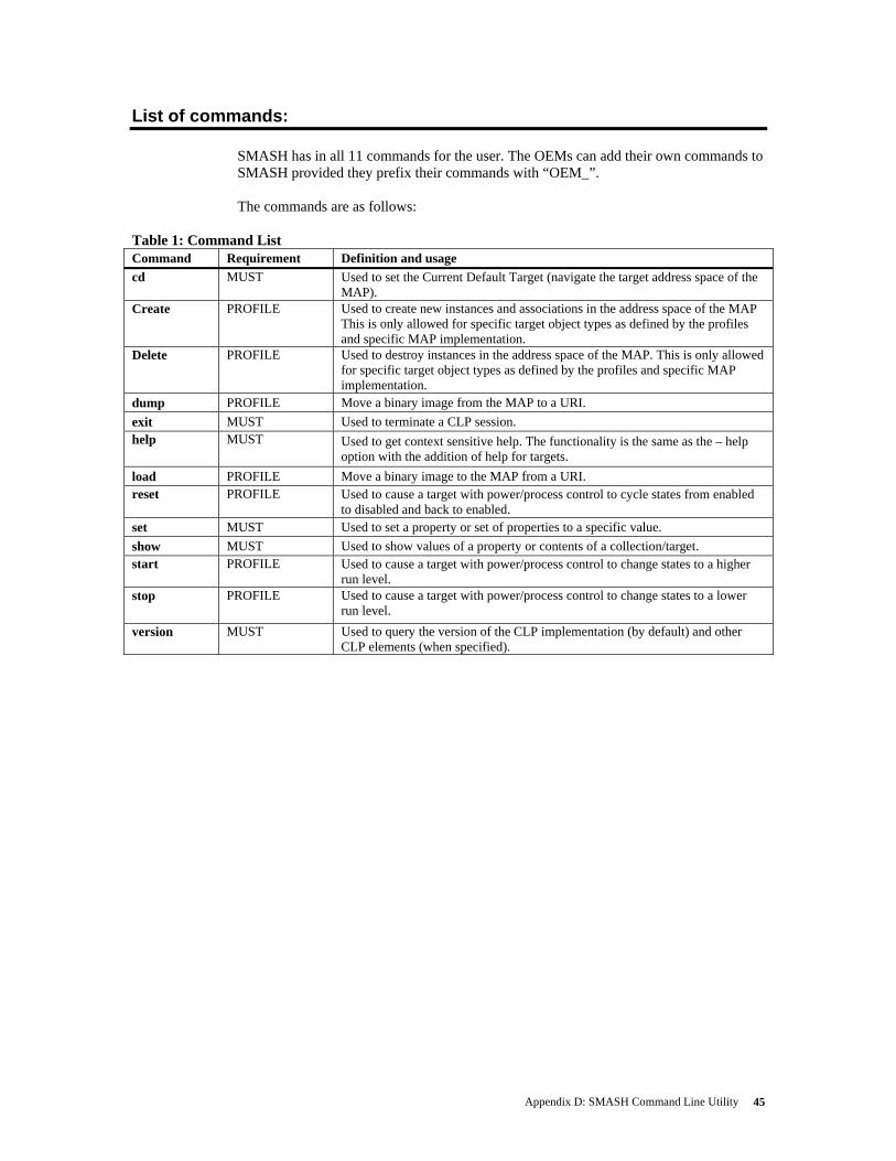
Appendix D: SMASH Command Line Utility 45
List of commands: SMASH has in all 11 commands for the user. The OEMs can add their own commands to SMASH provided they prefix their commands with “OEM_”. The commands are as follows:
Table 1: Command List Command Requirement Definition and usage cd MUST Used to set the Current Default Target (navigate the target address space of the
MAP). Create PROFILE Used to create new instances and associations in the address space of the MAP
This is only allowed for specific target object types as defined by the profiles and specific MAP implementation.
Delete PROFILE Used to destroy instances in the address space of the MAP. This is only allowed for specific target object types as defined by the profiles and specific MAP implementation.
dump PROFILE Move a binary image from the MAP to a URI. exit MUST Used to terminate a CLP session. help MUST Used to get context sensitive help. The functionality is the same as the – help
option with the addition of help for targets. load PROFILE Move a binary image to the MAP from a URI. reset PROFILE Used to cause a target with power/process control to cycle states from enabled
to disabled and back to enabled. set MUST Used to set a property or set of properties to a specific value. show MUST Used to show values of a property or contents of a collection/target. start PROFILE Used to cause a target with power/process control to change states to a higher
run level. stop PROFILE Used to cause a target with power/process control to change states to a lower
run level. version MUST Used to query the version of the CLP implementation (by default) and other
CLP elements (when specified).
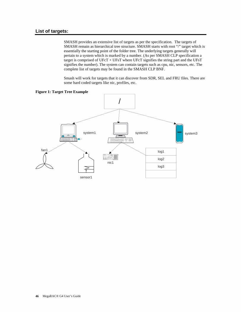
MegaRAC® G4 User’s Guide 46
List of targets: SMASH provides an extensive list of targets as per the specification. The targets of SMASH remain as hierarchical tree structure. SMASH starts with root “/” target which is essentially the starting point of the folder tree. The underlying targets generally will pertain to a system which is marked by a number. (As per SMASH CLP specification a target is comprised of UFcT + UFsT where UFcT signifies the string part and the UFsT signifies the number). The system can contain targets such as cpu, nic, sensors, etc. The complete list of targets may be found in the SMASH CLP BNF. Smash will work for targets that it can discover from SDR, SEL and FRU files. There are some hard coded targets like nic, profiles, etc.
Figure 1: Target Tree Example
/
iMacsystem1 system2 system3
fan1
sensor1
log3
log2
log1
nic1

Appendix D: SMASH Command Line Utility 47
The lists of targets that SMASH CLP currently supports are • system • sensor • tempsensor • profile • nic • logs • admin • cpu • accounts • record • hdwr The number of targets will depend on the discovery mechanism of the SMASH CLP. The number of entries in the SDR file will dictate the number of targets.
Working with SMASH- CLP
How to login Log in to the G3/G4 using the userid and password. In G3, from the command prompt one has to type SMASH and the SMASH CLP prompt will come forth.
Display the list of targets one can work with The following command will enlist the targets that SMASH CLP will support.
show –display targets This command will show the targets in the current default target (CDT). This means that if we in “/” folder then the above command will show the targets under root. If we are in a target, say system1, then the above command will list all the available targets under /system1 only.
How to get the target list under another target from CDT:
cd /system2 UFiP = /system2
show –display /system1

MegaRAC® G4 User’s Guide 48
Changing the Current Default Target: The command to change the target is cd.
cd /system1
cd .. cd /system1/cpu1/sensor1 cd ../../..
How to get help
The command to get help is to type: help. Associate help with the command name and the help for that command will show up.
help show show –help
How to check values of sensors or targets
The command to use is show and then we have to associate a target and the property with it.
show /sensor1 This will show the values associated with the sensor1. To see one particular value of the target we have to use the property keyword for the command.
show –display properties = IP /nic1 To see one or more properties for a particular target we can use multiple properties.
show –display properties = (IP, MAC) /nic1
How to set the values of the sensor or targets The “SET” command is used to modify the values of the targets.
set /nic1 ip=10.0.0.23

Appendix D: SMASH Command Line Utility 49
Using advanced options:
(A)ll option The –a(ll) option shows all properties of the targets.
(L)evel option The level option shows the properties of targets down to the level “n” specified in the command.
show –l 3 /system1 This command will show the properties of the targets up to the third level starting from the CDT or the target in the command line.
(E)xamine option The examine option is used to check the correctness of the command. This option will not execute the command but only say if the command given is ok or not.
cd –examine /system1
Display option The display option is used to display the properties of targets. If display is associated with “all” then it shows all the properties of the target.
Format option The format option specifies the output format of the commands. The formats are plain text (default), clpxml, clpcsv, clpkeyword.
show –format=clpxml –display targets.
Wildcard option Instead of UFsT one can use “*” to indicate all targets. Suppose under a CDT we have sensor1 to sensor10. To see the value of all the sensors we can just use sensor*. It will enlist all the sensor data.
show –display properties= IP /nic*

MegaRAC® G4 User’s Guide 50
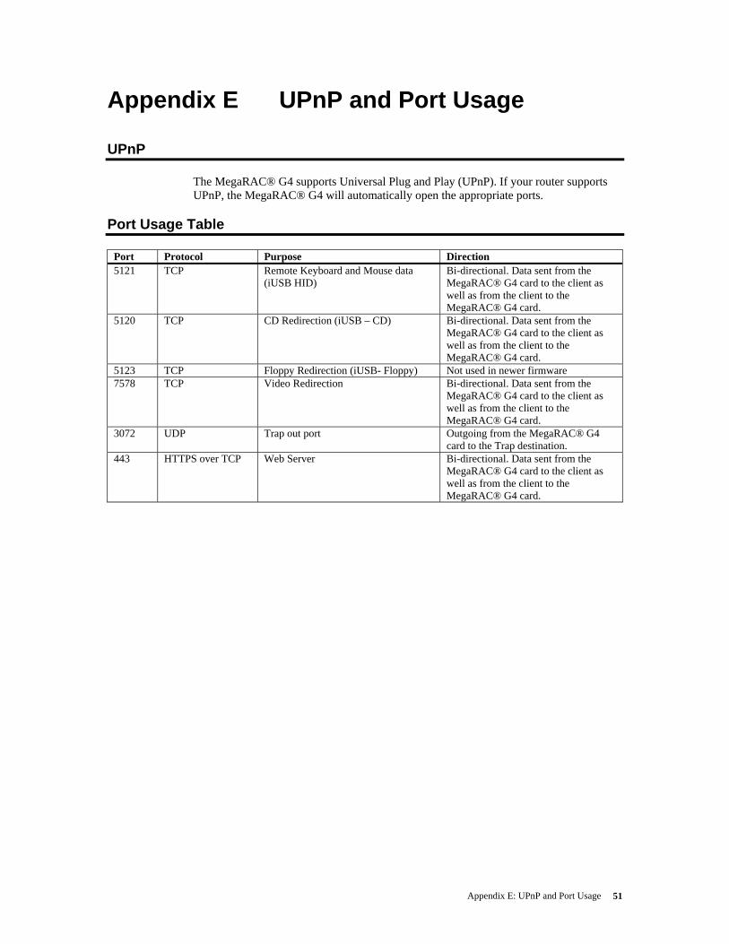
Appendix E: UPnP and Port Usage 51
Appendix E UPnP and Port Usage
UPnP
The MegaRAC® G4 supports Universal Plug and Play (UPnP). If your router supports UPnP, the MegaRAC® G4 will automatically open the appropriate ports.
Port Usage Table
Port Protocol Purpose Direction 5121 TCP Remote Keyboard and Mouse data
(iUSB HID) Bi-directional. Data sent from the MegaRAC® G4 card to the client as well as from the client to the MegaRAC® G4 card.
5120 TCP CD Redirection (iUSB – CD) Bi-directional. Data sent from the MegaRAC® G4 card to the client as well as from the client to the MegaRAC® G4 card.
5123 TCP Floppy Redirection (iUSB- Floppy) Not used in newer firmware 7578 TCP Video Redirection Bi-directional. Data sent from the
MegaRAC® G4 card to the client as well as from the client to the MegaRAC® G4 card.
3072 UDP Trap out port Outgoing from the MegaRAC® G4 card to the Trap destination.
443 HTTPS over TCP Web Server Bi-directional. Data sent from the MegaRAC® G4 card to the client as well as from the client to the MegaRAC® G4 card.

MegaRAC® G4 User’s Guide 52

Appendix F: MAC Address Map 53
Appendix F MAC Address Map
MAC Address Location Description
00-40-D9-02-9B-3C Server Room, Rack 2, 5 Windows 2003 Advanced Server, Mail Server

MegaRAC® G4 User’s Guide 54
Notes
Index 55
Index
A Add New User, 25 Alert - Modify Alert, 27 Alert List, 27 Applicable Documents and References:,
43 Avoid Electro-Static Discharge (ESD),
3
B Before You Start, 3 BIOS, 3, 7, 23, 37, 41 BMC Not Responding, 35
C Cannot Power On the Host System Remotely, 36
Changing the Current Default Target:, 48
Configuration Group, 20, 23 Connecting using Hyper Terminal, 37, 42 Console Redirection Window, 31
D Default Root User Name and Password,
43 Default User Name and Password, 19 Delete User, 24, 26 Device, 7, 8, 9, 33 Display the list of targets one can work with, 47
E Event Log, 1, 23
F Features, 1 Figure 1 Target Tree Example, 46
Firmware Update, 34
G General Information Group, 20
H Hardware Installation, 3 Hardware Setup, 37, 41 Help, 33 How to check values of sensors or targets, 48
How to get help, 48 How to get the target list under another target from CDT:, 47
How to login, 47 How to set the values of the sensor or targets, 48
I Installing Your MegaRAC® G4 Card, 3 Introduction, 1, 44 Introduction:, 44 IPMB (Intelligent Platform Management Bus), 17
J J1 JTAG (Joint Test Action Group) ICE (In-Circuit Emulator) Connector, 11
J10 Serial Port, 6, 13 J14 and J15 I2C Clock/Data PCI Bypass Jumper, 14
J18 MegaRAC® Feature Cable, 6, 15 J5 Recovery/Configuration Mode Jumper, 11
J9 Service Connector, 13
K Keyboard, 31, 51
L Launch Redirection, 30 LDAP Settings, 29 List of commands:, 45 List of targets:, 46 Logging In, 43 Logging Out, 34
M MAC Address Map, 53 Maintenance Group, 20, 33 MegaRAC® G4 Card Layout, 4, 5, 11
MegaRAC® G4 User’s Guide 56
MegaRAC® G4 Card Layout and Connection Guide, 5
MegaRAC® G4 GUI Explained, 20 MegaRAC® G4 GUI Overview, 19 Menu Bar, 20 Modify User, 24, 26 Mouse, 28, 30, 32, 51 Mouse Mode Settings, 28
N Network Settings, 23
O Options, 7, 21, 32 Overview, 39, 41
P Port Usage Table, 51 Power Status and Control, 33 Prerequisites, 41 Problem, 35, 36
R Remote Console Shortcut Key Combinations, 30
Remote Control Group, 20, 30
S Send Test Alert, 27 Sensor Monitoring Options, 21 Sensor Reading, 22 Serial Over LAN, 37 Server Health Group, 20 Setup your Client System’s Internet Browser, 10
SMASH CLP Architecture:, 44 SMASH Command Line Utility, 41
Solution, 35, 36 SSL Configuration, 28 Step 1 Unpack the MegaRAC® G4 card (and check jumper settings), 4
Step 2 Plug in the MegaRAC® G4 card into the Host System and Attach Internal Cables, 5
Step 3 Connect External Cables, 7 Step 4 Confirm the Motherboard’s BIOS Settings, 7
Step 5 Initial Configuration of the MegaRAC® G4 card, 8
Step 6 Install/Boot to an Operating System, 10
Symptom, 35, 36 System Information, 20
T Table 1 Command List, 45
Troubleshooting, 35
U UPnP, 8, 9, 51 UPnP and Port Usage, 51 User List, 24 Using advanced options:, 49 Using Your MegaRAC® G4, 19
V Video, 31, 32, 51
W What is SMASH:, 44 Wildcard option, 49 Working with SMASH- CLP, 47