Project 1 Building Construction 2
19
Building Construction II Project 1 - Temporary Bus Shelter Group Members: Low En Huey 0317889 Tan Jo Lynn 0318518 Teo Hong Wei 0322990 Tiong Jia Min 0323763 Yan Wai Chun 0319626 Tutor : Ms. Norita Johar 1
Transcript of Project 1 Building Construction 2

Building Construction II
Project 1 - Temporary Bus Shelter
Group Members:
Low En Huey 0317889
Tan Jo Lynn 0318518
Teo Hong Wei 0322990
Tiong Jia Min 0323763
Yan Wai Chun 0319626
Tutor : Ms. Norita Johar
1

C o n t e n t
I n t r o d u c t i o n 3
D e s i g n d e v e l o p m e n t 4 - 5
T e c h n i c a l d r a w i n g 6 - 8
C o n s t r u c t i o n p r o c e s s 9 - 1 1
M a t e r i a l s 1 2
J o i n t s d e t a i l s 1 3 - 1 5
L o a d a n d f o r c e s 1 6 - 1 7
C o n c l u s i o n 1 8
R e f e r e n c e s 1 9
2

I n t r o d u c t i o n
This subject allows student to experience and understand the importance of skeletal construction as it is one of the most widelyused structures for building support. In a group of five, we are to construct a temporary bus shelter that can accommodate 5-6 people using the scale of 1:20. The maximum base size of the bus shelter is 400mm x 800mm with the maximum height of 600mm. The bus shelter is elevated 50mm from the ground. We are encouraged to use recycled materials to construct the bus shelter
O b j e c t i v e s
- To understand how a skeletal structure reacts under loading.
- To demonstrate a convincing understanding of how skeletal construction works.
- To be able to manipulate skeletal construction to solve an oblique design problem.
- Apply construction system in design.
- Recognise the implication o construction system in designs.
- Analyse the issues of strength, stiffness and stability of structures including modes of structural systems, forces, stress and strain and laws of static.
L e a r n i n g o u t c o m e s
3

D e s i g n d e v e l o p m e n t
S k e t c h e s
4

D e s i g n d e v e l o p m e n t
M o c k u p 0 1
M o c k u p 0 2
M o c k u p 0 3
Random arrangement of cross braces result in uneven forces. Upper roof has no perpendicular support.
Adding seats and adjusted bracings for even support of the upper roof.
Carefully arranged cross bracing and different thickness of components are used result in a more stable structure.
5

T E C H N I C A L D R AW I N G S
FRONT ELEVATIONSCALE 1:5
BACK ELEVATION SCALE 1:5
6

T E C H N I C A L D R AW I N G S
LEFT ELEVATION SCALE 1:5
RIGHT ELEVATION SCALE 1:5
7

T E C H N I C A L D R AW I N G S
FLOOR PLAN SCALE 1:5
8

C o n s t r u c t i o n p r o c e s s
Wood are measured to correct dimensions to be cut.
Cutting wood to correct sizes . Ground beam are laid out properly.
Floor joists are arranged accordingly.
Floor joists are then nailed to the ground beam.
The main column structures are drilled to connect to the ground beams.
Nuts and bolts are installed at the joints.
Columns are set up.
Laying out the roof frame. Purlins are nailed to the roof beams.
Screwing the tie plate to the wood.
Installed tie plate. 9

C o n s t r u c t i o n p r o c e s s
Lower roof frame and floor frame are completed.
Measuring the plywood sheet to be cut properly.
Plywood sheet is precisely cut at the corners.
Arranging the plywood sheet on the floor frame.
Plywood sheet is completely nailed to the floor frame.
Nailing the plywood to the floor frame.
Setting up the diagonal wall studs.
The studs are adjusted to correct angle.
Walls studs are labelled for installation.
The studs are glued to the beam using wood glue.
Silver paper is used as an representation of pin joint base.
Setting up the bracings. 10

C o n s t r u c t i o n p r o c e s s
Holes on the tie plates are made by nailing through metal sheet.
DIY tie plates.
Setting up the upper roof frame.
Main frame and the secondary structures are constructed.
Secondary structures are completed.
The roof material is cut to correct size and
T i e p l a t e s c o n s t r u c t i o n
11

M a t e r i a l s
Representation : Corrugated Plastic Board Actual : Poly-carbonate Roof
• Able to withstand force and virtually unbreakable.
• High percentage of UV blockage.• Light weight and easy installation.
Representation : WoodActual : Chengal Wood
• Very resistant to termite attack.• Weather resistant. • High strength.
Representation : Plywood Sheet Actual : Pressured Treated Wood
• Insect resistance.• Long lasting up to many years.• Able to withstand scratches and dent.
f r a m e
f l o o r i n g
r o o f
12

J O I N T p h o t o s
1
2
3
5
4
1 4
6
2
6
3
5
7
7
13
J o i n t d e t a i l s
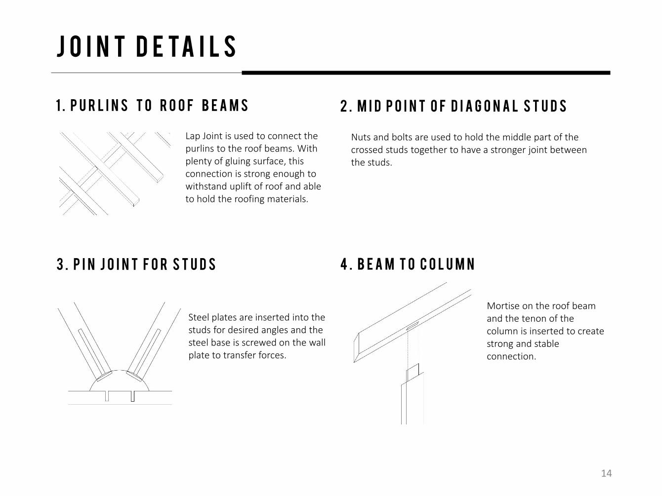
1 . P u r l i n s t o r o o f b e a m s
Lap Joint is used to connect the purlins to the roof beams. With plenty of gluing surface, this connection is strong enough to withstand uplift of roof and able to hold the roofing materials.
2 . M i d p o i n t o f d i a g o n a l s t u d s
Nuts and bolts are used to hold the middle part of the crossed studs together to have a stronger joint between the studs.
3 . P i n j o i n t f o r s t u d s 4 . B e a m t o c o l u m n
Steel plates are inserted into the studs for desired angles and the steel base is screwed on the wall plate to transfer forces.
Mortise on the roof beam and the tenon of the column is inserted to create strong and stable connection.
14
J o i n t d e t a i l s
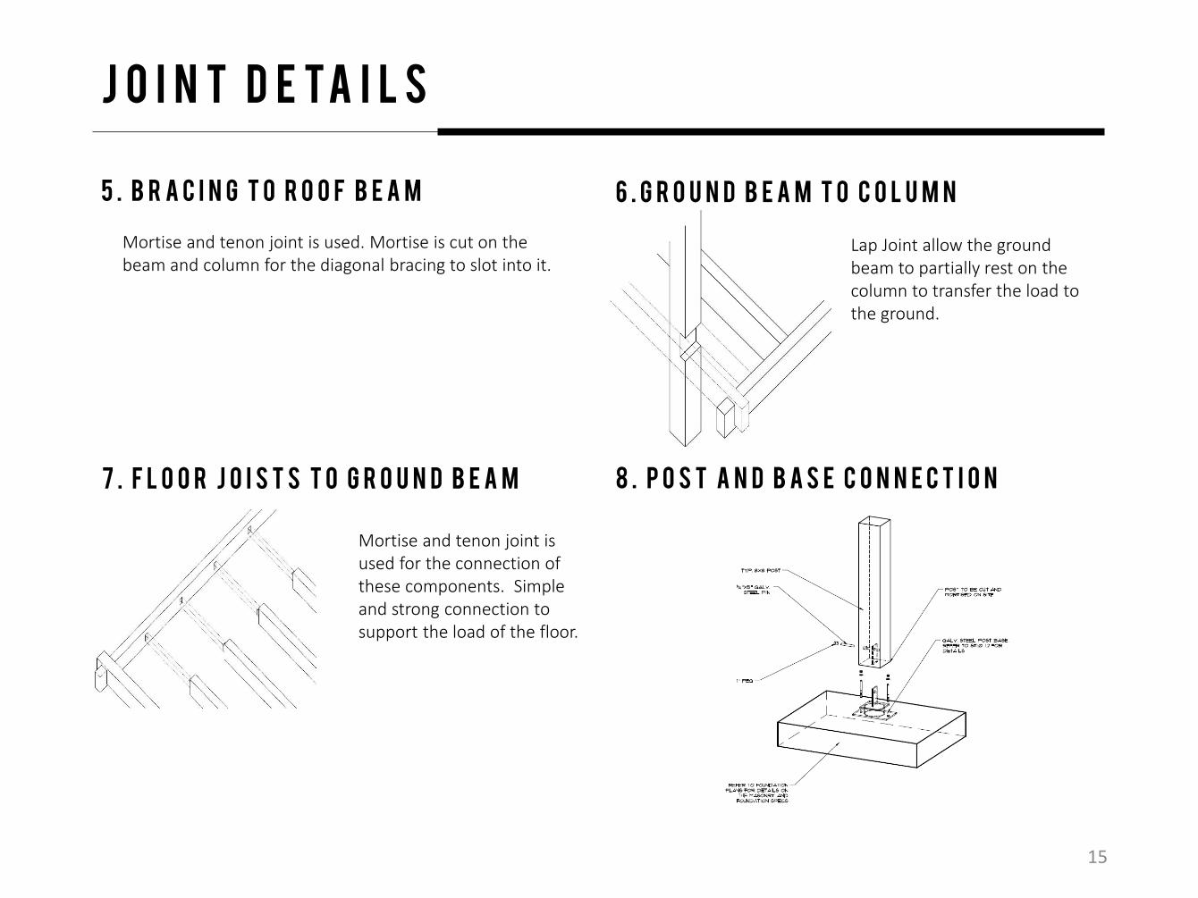
5 . B r a c i n g t o r o o f b e a m
Mortise and tenon joint is used. Mortise is cut on the beam and column for the diagonal bracing to slot into it.
6 . G r o u n d b e a m t o c o l u m n
7 . F L O O R J O I S T S T O G R O U N D B E A M 8 . P o s t a n d b a s e c o n n e c t i o n
Mortise and tenon joint is used for the connection of these components. Simple and strong connection to support the load of the floor.
Lap Joint allow the ground beam to partially rest on the column to transfer the load to the ground.
15
L o a d a n d f o r c e s
WIND
L a t e r a l f o r c e d e s i g n
WIND
GROUND MOTION
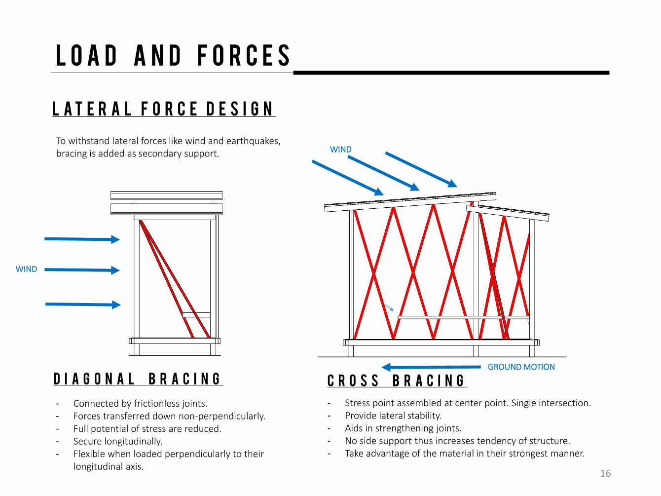
To withstand lateral forces like wind and earthquakes, bracing is added as secondary support.
- Connected by frictionless joints.- Forces transferred down non-perpendicularly.- Full potential of stress are reduced. - Secure longitudinally. - Flexible when loaded perpendicularly to their
longitudinal axis.
- Stress point assembled at center point. Single intersection. - Provide lateral stability.- Aids in strengthening joints.- No side support thus increases tendency of structure.- Take advantage of the material in their strongest manner.
D i a g o n a l b r a c i n g C r o s s b r a c i n g
16

L o a d a n d f o r c e s
The common live loads for a bus shelter is the people waiting and sitting in it. Other than that, the bus shelter is able to withstand extra movable load like luggage and extra items that people carry along.
L i v e l o a d d e s i g n
d e a d l o a d d e s i g n
Loads are transferred perpendicularly to the ground. Furthermore, FREE HANGING of roof was incorporated to enhance the spatial experiences of the design. Therefore, bracings and secondary diagonal supports are inserted to reduce full potential of load support by the main vertical planes (columns) and to support the load of the horizontal planes (roof structures).
17
C o n c l u s i o n
On median, each group worked for around at the Carpentry Workshop but we have carried out our tasks in the workshop for about 5 days due to experiments executed for the production of joints and load sustainability testing. We used the extra workshop schedules to combat our faults in the construction of our joints and we managed to catch up with the agenda onthe third and forth day of the construction in the workshop.
Upon completion, we have learnt the knowledge of applications of skeletal construction and different kind of joints to actual construction and design. We have also understood the capability of a structure to withstand and react to the loads exerted. Beside that, beyond recall, we were able to manipulate the construction to solve design problem and recognize the implication of construction systems upon creation.
18

R e f e r e n c e s
19
http://www.buildmagazine.org.nz/articles/show/distributing-lateral-loads-in-timber-framed-buildings/ http://kisi.deu.edu.tr/ozgur.ozcelik/AR361/AR361_Lecture_1.pdf http://zhan.renren.com/structuresmaterials?gid=3602888498044603443&from=post&checked=true http://www.steelconstruction.info/Bracing_systems http://www.ripsdiy.co.za/woodjoins.shtml http://www.vermonttimberworks.com/learn/timber-frame-joinery/purlins-and-joists/ http://timberframehq.com/construction-details/masonryconcrete-to-timber/
Photo Sources : All members of this group.