1,2, Moritz Kahlert 3 , Malte Vollmer 3 , Thomas Niendorf
10
materials Article Tribological Performance of Additively Manufactured AISI H13 Steel in Different Surface Conditions Elisabeth Guenther 1,2 , Moritz Kahlert 3 , Malte Vollmer 3 , Thomas Niendorf 3 and Christian Greiner 1,2, * Citation: Guenther, E.; Kahlert, M.; Vollmer, M.; Niendorf, T.; Greiner, C. Tribological Performance of Additively Manufactured AISI H13 Steel in Different Surface Conditions. Materials 2021, 14, 928. https:// doi.org/10.3390/ma14040928 Academic Editor: Adam Grajcar Received: 22 January 2021 Accepted: 11 February 2021 Published: 16 February 2021 Publisher’s Note: MDPI stays neutral with regard to jurisdictional claims in published maps and institutional affil- iations. Copyright: © 2021 by the authors. Licensee MDPI, Basel, Switzerland. This article is an open access article distributed under the terms and conditions of the Creative Commons Attribution (CC BY) license (https:// creativecommons.org/licenses/by/ 4.0/). 1 Karlsruhe Institute of Technology (KIT), Institute for Applied Materials (IAM), Kaiserstrasse 12, 76131 Karlsruhe, Germany; [email protected] 2 KIT IAM-CMS MicroTribology Center (μTC), Strasse am Forum 5, 76131 Karlsruhe, Germany 3 Institute of Materials Engineering, Universität Kassel, Mönchebergstraße 3, 34125 Kassel, Germany; [email protected] (M.K.); [email protected] (M.V.); [email protected] (T.N.) * Correspondence: [email protected]; Tel.: +49-721-204-327-42 Abstract: Additive manufacturing of metallic tribological components offers unprecedented degrees of freedom, but the surface roughness of most as-printed surfaces impedes the direct applicability of such structures, and postprocessing is necessary. Here, the tribological performance of AISI H13 steel samples was studied. These were additively manufactured through laser powder bed fusion (L-PBF), also referred to as selective laser melting (SLM). Samples were tested in four different surface conditions: as-printed, polished, ground and polished, and laser-surface-textured (LST) with round dimples. Friction experiments were conducted in a pin-on-disk fashion against bearing steel disks under lubrication with an additive-free mineral base oil for sliding speeds between 20 and 170 mm/s. Results demonstrated that, among the four surface treatments, grinding and polishing resulted in the lowest friction coefficient, followed by the as-printed state, while both polishing alone and laser-surface texturing increased the friction coefficient. Surprisingly, direct correlation between surface roughness and friction coefficient, i.e., the rougher the surface was, the higher the friction force, was not observed. Wear was minimal in all cases and below what could be detected by gravimetrical means. These results highlight the need for an adequate post-processing treatment of additively manufactured parts that are to be employed in tribological systems. Keywords: tribology; additive manufacturing; selective laser melting; surface roughness 1. Introduction The global need to conserve resources and energy has several consequences. For one, it is desirable to reduce waste during the manufacturing of components; second, the lifetime and energy necessary to operate a component or system ought to be optimized. The first aspect can be addressed through the near net-shape manufacturing of components by 3D-printing, i.e., additive manufacturing (AM), and through the high degree of geomet- ric freedom provided by respective techniques, eventually leading to additional weight reduction, e.g., through topology optimization [1–3]. The second aspect can be approached by better tribological practices. This is true as many engineering systems contain moving parts and are thereby susceptible to friction and wear. Tribological losses are responsible for more than 20% of the global primary energy usage [4]. It is, therefore, obvious that the additive manufacturing of tribological components with superior friction and wear properties may hold significant potential to save precious resources and energy. At the same time, realizing this potential is seriously impeded mainly due to the high surface roughness of as-printed metallic parts produced by additive manufacturing [5–7]. In this context, the literature mainly investigated parts that were manufactured by laser powder bed fusion (L-PBF), also referred to as selective laser melting (SLM) [8–13]. Using this method, Al–Si and Ti6Al4V alloys, and 316L steel were printed and tested with or without further changes to the surfaces themselves [8–13]. Moreover, hybrid Materials 2021, 14, 928. https://doi.org/10.3390/ma14040928 https://www.mdpi.com/journal/materials
Transcript of 1,2, Moritz Kahlert 3 , Malte Vollmer 3 , Thomas Niendorf
materials
Article
Tribological Performance of Additively Manufactured AISI H13Steel in Different Surface Conditions
Elisabeth Guenther 1,2, Moritz Kahlert 3 , Malte Vollmer 3 , Thomas Niendorf 3 and Christian Greiner 1,2,*
�����������������
Citation: Guenther, E.; Kahlert, M.;
Vollmer, M.; Niendorf, T.; Greiner, C.
Tribological Performance of
Additively Manufactured AISI H13
Steel in Different Surface Conditions.
Materials 2021, 14, 928. https://
doi.org/10.3390/ma14040928
Academic Editor: Adam Grajcar
Received: 22 January 2021
Accepted: 11 February 2021
Published: 16 February 2021
Publisher’s Note: MDPI stays neutral
with regard to jurisdictional claims in
published maps and institutional affil-
iations.
Copyright: © 2021 by the authors.
Licensee MDPI, Basel, Switzerland.
This article is an open access article
distributed under the terms and
conditions of the Creative Commons
Attribution (CC BY) license (https://
creativecommons.org/licenses/by/
4.0/).
1 Karlsruhe Institute of Technology (KIT), Institute for Applied Materials (IAM), Kaiserstrasse 12,76131 Karlsruhe, Germany; [email protected]
2 KIT IAM-CMS MicroTribology Center (µTC), Strasse am Forum 5, 76131 Karlsruhe, Germany3 Institute of Materials Engineering, Universität Kassel, Mönchebergstraße 3, 34125 Kassel, Germany;
[email protected] (M.K.); [email protected] (M.V.); [email protected] (T.N.)* Correspondence: [email protected]; Tel.: +49-721-204-327-42
Abstract: Additive manufacturing of metallic tribological components offers unprecedented degreesof freedom, but the surface roughness of most as-printed surfaces impedes the direct applicabilityof such structures, and postprocessing is necessary. Here, the tribological performance of AISI H13steel samples was studied. These were additively manufactured through laser powder bed fusion(L-PBF), also referred to as selective laser melting (SLM). Samples were tested in four differentsurface conditions: as-printed, polished, ground and polished, and laser-surface-textured (LST) withround dimples. Friction experiments were conducted in a pin-on-disk fashion against bearing steeldisks under lubrication with an additive-free mineral base oil for sliding speeds between 20 and170 mm/s. Results demonstrated that, among the four surface treatments, grinding and polishingresulted in the lowest friction coefficient, followed by the as-printed state, while both polishingalone and laser-surface texturing increased the friction coefficient. Surprisingly, direct correlationbetween surface roughness and friction coefficient, i.e., the rougher the surface was, the higher thefriction force, was not observed. Wear was minimal in all cases and below what could be detected bygravimetrical means. These results highlight the need for an adequate post-processing treatment ofadditively manufactured parts that are to be employed in tribological systems.
Keywords: tribology; additive manufacturing; selective laser melting; surface roughness
1. Introduction
The global need to conserve resources and energy has several consequences. Forone, it is desirable to reduce waste during the manufacturing of components; second, thelifetime and energy necessary to operate a component or system ought to be optimized.The first aspect can be addressed through the near net-shape manufacturing of componentsby 3D-printing, i.e., additive manufacturing (AM), and through the high degree of geomet-ric freedom provided by respective techniques, eventually leading to additional weightreduction, e.g., through topology optimization [1–3]. The second aspect can be approachedby better tribological practices. This is true as many engineering systems contain movingparts and are thereby susceptible to friction and wear. Tribological losses are responsiblefor more than 20% of the global primary energy usage [4]. It is, therefore, obvious thatthe additive manufacturing of tribological components with superior friction and wearproperties may hold significant potential to save precious resources and energy. At thesame time, realizing this potential is seriously impeded mainly due to the high surfaceroughness of as-printed metallic parts produced by additive manufacturing [5–7].
In this context, the literature mainly investigated parts that were manufactured bylaser powder bed fusion (L-PBF), also referred to as selective laser melting (SLM) [8–13].Using this method, Al–Si and Ti6Al4V alloys, and 316L steel were printed and testedwith or without further changes to the surfaces themselves [8–13]. Moreover, hybrid
Materials 2021, 14, 928. https://doi.org/10.3390/ma14040928 https://www.mdpi.com/journal/materials
Materials 2021, 14, 928 2 of 10
additive manufacturing methods consisting of laser cladding, milling, ultrasonic surfacerolling [14], and different coating systems [15,16] were used to improve the tribologicalperformance of additively manufactured materials. The authors of these studies were ableto show the possibility of using the SLM process for directly printing coating materialonto additively manufactured substrate materials, which opens up a wide field of newapplications. However, the present study focuses on the tribological performance ofadditively manufactured steel. Bajaj et al. [1] reported that there was no conclusive availableinformation on the wear performance of SLM-produced AISI H13. Investigations on toolsteel [17] and high-speed steel [18] revealed the tendency of the wear rate, i.e., the removedvolume per sliding distance, to decrease with the increased hardness of the material,resulting in increased wear resistance of additively manufactured parts.
When comparing the tribological performance of 316L stainless-steel samples thatwere processed by SLM to traditional processes, both sets of samples were polished to thesame level of surface roughness [9]. These experiments found that SLM parts performedeither better or worse than traditionally manufactured ones did, depending on the counterbody material. In another study, 316L surfaces were again ground and polished, and theeffect of different build-up directions was investigated [13]. When purposefully printingstainless-steel parts with a varying degree of porosity, due to these, the friction coefficientin the hydrodynamic branch of the Stribeck curve [19] decreased compared to that infully dense samples [11]. To achieve this effect, samples were not used as printed, butpolished manually to a root-mean-square (RMS) roughness of 100 nm [11]. However, suchpost-processing could impede the usefulness of additive manufacturing. The need to alterthe as-printed surface was also addressed for Ti6Al4V. Again, samples were polished after3D-printing and subjected to an oxidation treatment to improve their wear resistance [12].Interestingly, the surface roughness inherent to additive manufacturing in this case wasused as a means to study the polishing processes of rough surfaces [20]. Grinding andpolishing was also necessary when a CoCrFeMnNi high-entropy alloy was processed viaan additive manufacturing route, and tribologically tested [21].
Selective laser melting was also employed to create ceramic coatings by additivemanufacturing, such as ZrB2, ZrC, B4C [15], a NiCrAlY bond coat [16], and a nickel-basedsuperalloy [22], to name a few examples. These coatings can also increase wear resistance.
This brief and by no means comprehensive overview over some of the existing lit-erature demonstrates in almost all cases that, when the tribological performance of partsprocessed via additive manufacturing was assessed, the samples were ground and polishedbefore they were subjected to the tribological load. However, what was not answered so farwas how much of an effect this smoothing of the as-printed samples had on friction forces,or whether it was necessary at all. As the strategic morphological texturing of surfaces is aprolific field of tribological research [23–25], a certain amount of surface roughness couldbe beneficial to friction and wear. Therefore, in the present study H13 steel was processedusing SLM and then tested to assess friction performance in four different surface states:as-printed, ground, ground and polished, and deliberately laser-surface-textured (LST)with round dimples. Friction forces were measured in a lubricated pin-on-disk contactagainst bearing steel disks, mainly in the mixed lubrication part of the Stribeck curve.These results are intended to identify how much difference in terms of friction coefficientthese four post-processing treatments provoke. These first experiments will hopefullyinspire other, more in-depth experimental and modeling research into this important topic,ultimately allowing the strategic 3D-printing of metals for tribological components withthe least amount of post-processing necessary.
2. Materials and Methods2.1. Additive Manufactoring
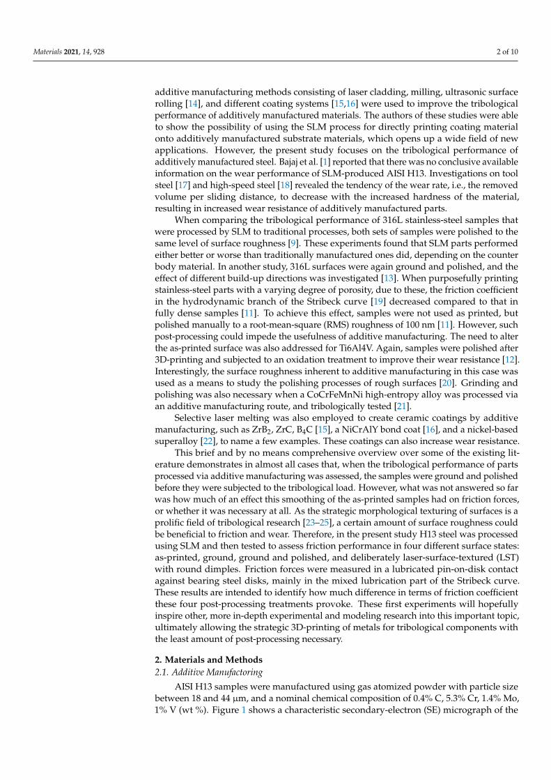
AISI H13 samples were manufactured using gas atomized powder with particle sizebetween 18 and 44 µm, and a nominal chemical composition of 0.4% C, 5.3% Cr, 1.4% Mo,1% V (wt %). Figure 1 shows a characteristic secondary-electron (SE) micrograph of the
Materials 2021, 14, 928 3 of 10
powder, revealing homogeneous morphology, and only a few satellites and oval particles,highlighted with white arrows. For selective laser melting, an SLM 280HL (SLM SolutionsGroup AG, Lubeck, Germany) equipped with a high-temperature substrate-plate heatingdevice was used. Cuboids with dimensions of 6 (width) × 40 (depth) × 40 mm (height)were built upright on the substrate plate, which was heated up to 200 ◦C during processing.One of the long axes was oriented along the build direction (BD) during SLM. Differentprocess parameters were used for contour and volume (Table 1).
Materials 2021, 14, x FOR PEER REVIEW 3 of 10
AISI H13 samples were manufactured using gas atomized powder with particle size between 18 and 44 µm, and a nominal chemical composition of 0.4% C, 5.3% Cr, 1.4% Mo, 1% V (wt %). Figure 1 shows a characteristic secondary-electron (SE) micrograph of the powder, revealing homogeneous morphology, and only a few satellites and oval particles, highlighted with white arrows. For selective laser melting, an SLM 280HL (SLM Solutions Group AG, Lubeck, Germany) equipped with a high-temperature substrate-plate heating device was used. Cuboids with dimensions of 6 (width) × 40 (depth) × 40 mm (height) were built upright on the substrate plate, which was heated up to 200 °C during pro-cessing. One of the long axes was oriented along the build direction (BD) during SLM. Different process parameters were used for contour and volume (Table 1).
Figure 1. Characteristic secondary-electron (SE) micrograph of AISI H13 powder used in the pre-sent study. Some satellites and oval particles are highlighted with white arrows.
Table 1. Process parameters used for manufacturing AISI H13 samples [26].
Area Power, W Velocity, mm/s Hatch Distance,
mm Layer Thickness,
µm Volume 270 700 0.12 30 Contour 100 400 - 30
An exposure strategy with a maximal scan-track length of 10 mm was chosen to melt the volume. Scan-track directions were rotated by 33° every layer. Afterwards, samples were mechanically released from the substrate plate.
2.2. Surface Treatment and Characterization From the cuboids printed through the SLM process described above, cylindrical sam-
ples of 8 mm in diameter and thickness of 5 mm were manufactured through electrical discharge machining, with their symmetry axis oriented perpendicular to the BD. For the as-printed samples, no further surface treatment was performed. Before and after the ex-periments, all samples were stored in a desiccator under a high vacuum.
For the polishing surface treatment, the as-built surfaces of the samples were manu-ally polished only with monocrystalline diamond suspensions of 3 and 1 µm in particle size (Strikers, Willich, Germany) for about 10 min each. Between polishing steps, samples were cleaned in isopropanol under ultrasound for 5 min.
“Ground and polished” samples were manually ground with SiC papers of mesh P220, P600, and P1200. This was followed by mechanical polishing on synthetic silk clothes (provided by Cloeren Technology GmbH, Wegberg, Germany) using monocrys-talline diamond suspensions with particle sizes of 3 and 1 µm (Struers, Willich, Germany)
Figure 1. Characteristic secondary-electron (SE) micrograph of AISI H13 powder used in the presentstudy. Some satellites and oval particles are highlighted with white arrows.
Table 1. Process parameters used for manufacturing AISI H13 samples [26].
Area Power, W Velocity, mm/s Hatch Distance, mm Layer Thickness, µm
Volume 270 700 0.12 30Contour 100 400 - 30
An exposure strategy with a maximal scan-track length of 10 mm was chosen to meltthe volume. Scan-track directions were rotated by 33◦ every layer. Afterwards, sampleswere mechanically released from the substrate plate.
2.2. Surface Treatment and Characterization
From the cuboids printed through the SLM process described above, cylindricalsamples of 8 mm in diameter and thickness of 5 mm were manufactured through electricaldischarge machining, with their symmetry axis oriented perpendicular to the BD. For theas-printed samples, no further surface treatment was performed. Before and after theexperiments, all samples were stored in a desiccator under a high vacuum.
For the polishing surface treatment, the as-built surfaces of the samples were manuallypolished only with monocrystalline diamond suspensions of 3 and 1 µm in particle size(Strikers, Willich, Germany) for about 10 min each. Between polishing steps, samples werecleaned in isopropanol under ultrasound for 5 min.
“Ground and polished” samples were manually ground with SiC papers of meshP220, P600, and P1200. This was followed by mechanical polishing on synthetic silk clothes(provided by Cloeren Technology GmbH, Wegberg, Germany) using monocrystallinediamond suspensions with particle sizes of 3 and 1 µm (Struers, Willich, Germany) forabout 10 min each. Between grinding and polishing steps, samples were sonicated inisopropanol for 5 min in order to remove debris.
Before the tribological experiments, each sample was sonicated for 15 min more inisopropanol. Before and after every tribological experiment, sample surfaces were doc-
Materials 2021, 14, 928 4 of 10
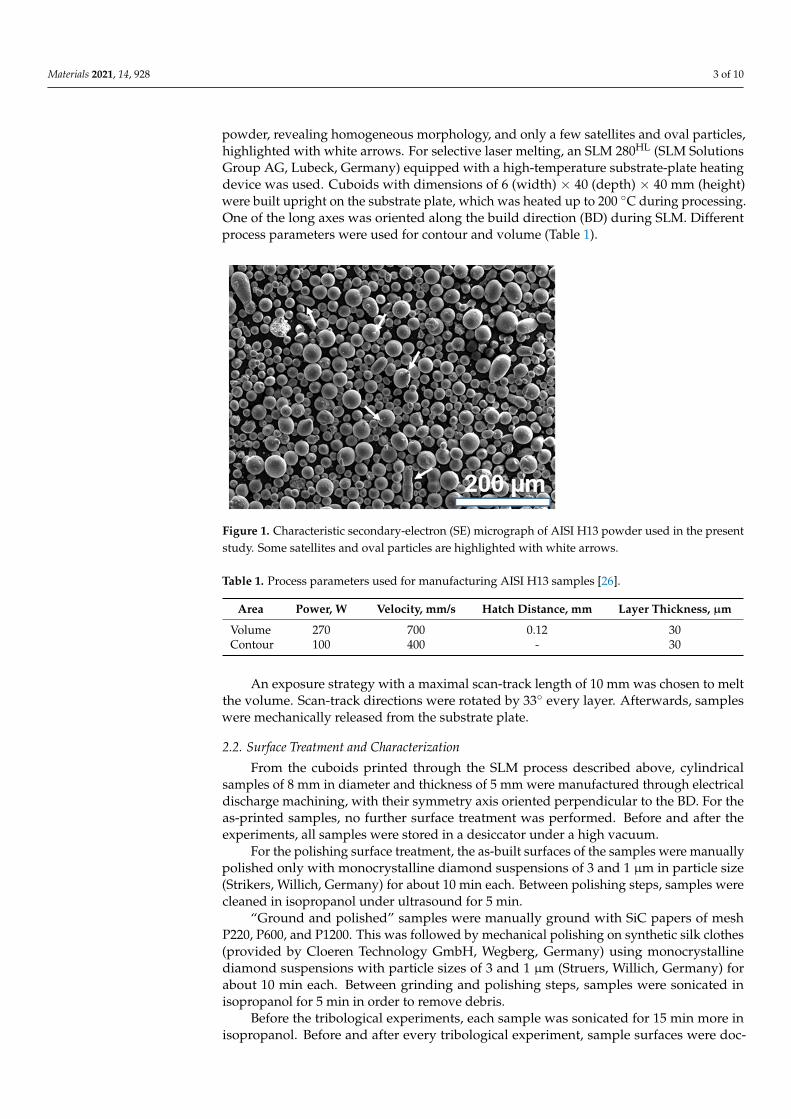
umented through optical micrographs taken with a VHX-600 digital optical microscope(Keyence, Osaka, Japan). Surface roughness was also measured with an optical profilome-ter (Sensofar PluNeox, Barcelona, Spain) before and after each experiment. Exemplarymicrographs for all four surface treatments before the tribological tests are presented inFigure 2.
Materials 2021, 14, x FOR PEER REVIEW 4 of 10
for about 10 min each. Between grinding and polishing steps, samples were sonicated in isopropanol for 5 min in order to remove debris.
Before the tribological experiments, each sample was sonicated for 15 min more in isopropanol. Before and after every tribological experiment, sample surfaces were docu-mented through optical micrographs taken with a VHX-600 digital optical microscope (Keyence, Osaka, Japan). Surface roughness was also measured with an optical profilome-ter (Sensofar PluNeox, Barcelona, Spain) before and after each experiment. Exemplary mi-crographs for all four surface treatments before the tribological tests are presented in Fig-ure 2.
Figure 2. Optical micrographs before tribological tests. (a) As-printed, (b) polished, (c) ground and polished, and (d) laser-surface-textured. H13 steel samples initially were prepared by selective laser melting (SLM). Magnification for each image chosen such to best represent samples. Un-melted powder in (a) is highlighted by white arrows.
2.3. Tribological Testing Tribological experiments were conducted with a laboratory pin-on-disk tribometer
from CSM Instruments (CSM Instruments, Peseux, Switzerland). Bearing steel 100Cr6 (AISI 5210, EisenSchmitt, Karlsruhe, Germany) disks with a diameter of 70 mm were used as counter bodies. Discs were hardened and tempered to Vickers hardness of about 800 HV. Hardness was quantified with a Q10A+ Vickers hardness tester (Qness GmbH, Gol-ling, Austria). Disks were ground to Ra roughness of 0.1 µm, measured by a Hommelwave Waveline W800 (Jenoptic AG, Jena, Germany) tactile profilometer. Waviness along the ra-dius where the tribological experiments were conducted was below 1 µm, as determined with a Sensofar PluNeox white light interferometer (Sensofar, Barcelona, Spain). Addi-tively manufactured H13 steel pins with a diameter of 8 mm were mounted in self-aligning holders. Once the pin had been mounted, it was placed on the disk and glued into the holder with a two-component epoxy (UHU Plus Sofortfest, Buehl, Germany), with the nor-mal load of 10 N already applied via dead weights. This process ensured a proper flat-on-flat contact. The epoxy was hardened for 15 min before 3 mL of FVA-2, a mineral base oil without additives, was added to allow for ample lubrication. At room temperature, this oil had a dynamic viscosity of approximately 80 mPa·s. For the tribological experiments, a characteristic speed profile was tested, starting at a sliding speed of 170 mm/s, which was
Figure 2. Optical micrographs before tribological tests. (a) As-printed, (b) polished, (c) ground andpolished, and (d) laser-surface-textured. H13 steel samples initially were prepared by selective lasermelting (SLM). Magnification for each image chosen such to best represent samples. Unmeltedpowder in (a) is highlighted by white arrows.
2.3. Tribological Testing
Tribological experiments were conducted with a laboratory pin-on-disk tribometerfrom CSM Instruments (CSM Instruments, Peseux, Switzerland). Bearing steel 100Cr6(AISI 5210, EisenSchmitt, Karlsruhe, Germany) disks with a diameter of 70 mm were usedas counter bodies. Discs were hardened and tempered to Vickers hardness of about 800 HV.Hardness was quantified with a Q10A+ Vickers hardness tester (Qness GmbH, Golling,Austria). Disks were ground to Ra roughness of 0.1 µm, measured by a HommelwaveWaveline W800 (Jenoptic AG, Jena, Germany) tactile profilometer. Waviness along theradius where the tribological experiments were conducted was below 1 µm, as determinedwith a Sensofar PluNeox white light interferometer (Sensofar, Barcelona, Spain). Additivelymanufactured H13 steel pins with a diameter of 8 mm were mounted in self-aligningholders. Once the pin had been mounted, it was placed on the disk and glued into theholder with a two-component epoxy (UHU Plus Sofortfest, Buehl, Germany), with thenormal load of 10 N already applied via dead weights. This process ensured a proper flat-on-flat contact. The epoxy was hardened for 15 min before 3 mL of FVA-2, a mineral baseoil without additives, was added to allow for ample lubrication. At room temperature, thisoil had a dynamic viscosity of approximately 80 mPa·s. For the tribological experiments, acharacteristic speed profile was tested, starting at a sliding speed of 170 mm/s, which wasreduced to 20 mm/s in 9 separate steps (100, 80, 70, 60, 50, 40, and 30 mm/s). Each slidingspeed was held for five minutes. This speed ramp was repeated 5 times. All presentedfriction data are the result of averaging these 5 ramps and at least 2 individual experiments.These sliding speeds were chosen to mainly test in the mixed lubrication regime and the
Materials 2021, 14, 928 5 of 10
transition to hydrodynamic lubrication, respectively. Ambient temperature during theexperiments was 23 ± 2 ◦C. Relative humidity was controlled to 40 ± 3% by enclosingthe setup in a Plexiglas box where humidity was equilibrated for at least 1 hour prior toevery experiment.
2.4. Laser Surface Texturing
Laser surface texturing (LST) was carried out directly on the as-printed surface of thecylindrical H13 steel samples with a diameter of 8 mm and a thickness of 5 mm, whichwere cut from the as-printed cuboids by electrical discharge machining. A Q-switchedYtterbium-doped fiber laser, Piranha II (Acsys Instruments, Kornwestheim, Germany), wasemployed. The wavelength was 1064 nm, and the laser source power was set to 11.2 W.Samples were textured with circular dimples of 40 µm in diameter and a packing densityof 10%. Dimple depth was kept constant at 4 µm. In previous experiments, this texturewas proven to be superior, especially in mixed lubrication where a reduction in frictionforces of up to 80% was found [27,28]. The debris that formed during laser ablation wasnot removed by an additional polishing step (see Figure 2d).
3. Results and Discussion
H13 steel was successfully processed by SLM, following process parameters alreadydetailed in previous work [26]. The final density of the steel cuboids was above 99%. Afterthe electrical discharge machining of cylinders for tribological experiments, samples wereeither left as-printed, solely polished, ground and polished, or laser-surface-textured withround dimples. Each of these surface treatments had an effect on surface roughness, withthe resulting average area surface roughness (Sa) values summarized in Table 2.
Table 2. Average area surface roughness Sa of additively manufactured H13 steel samples in surface conditions as-printed,polished, ground and polished, and laser-surface-textured before and after tribological testing. Surface roughness wasdetermined by white-light interferometry at five different positions on each sample. The given error is the standarddeviation of these measurements.
Unit As-Printed Polished Ground and Polished Laser-Textured
Sa,before (µm) 5.74 ± 0.40 5.64 ± 0.30 0.15 ± 0.05 3.80 ± 0.90Sa,after (µm) 6.70 ± 0.30 6.10 ± 0.40 0.06 ± 0.01 5.3 ± 0.60
The roughness data presented in Table 2 were not entirely as expected. First, anaverage areal surface roughness Sa in the range of 3 to 6 µm is quite rough. Second, itis surprising that surface roughness decreased upon laser surface texturing. The opticalmicrographs presented in Figure 2 support the interferometry results. Most probably theas-printed surface was so rough that LST decreased roughness due to partial remelting ofthe surface. One can also note that only polishing the as-printed surface did not change theroughness significantly. This is due to the fact that the surface roughness upon SLMwas influenced by many different factors contributing to the final appearance of theas-built surface [29]. Two of the most relevant aspects were partially melted powderparticles stuck to the surface (highlighted by arrows in Figure 2a) and general processinherent characteristics based on the layer-wise manufacturing principle and local melt-pool dynamics. Pure polishing was not able to fully flatten the surface, as the materialremoval rate was not sufficient to remove the roughness due to the inherent characteristicsof SLM, detailed above. Furthermore, some remaining powder particles can be seen inFigure 2b. Thus, roughness was still fairly pronounced in the polished condition, and theSa value was hardly affected (Table 2).
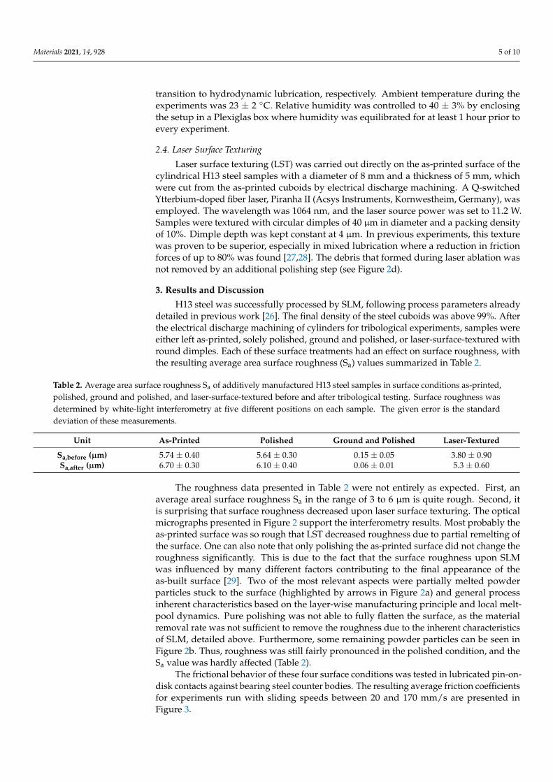
The frictional behavior of these four surface conditions was tested in lubricated pin-on-disk contacts against bearing steel counter bodies. The resulting average friction coefficientsfor experiments run with sliding speeds between 20 and 170 mm/s are presented inFigure 3.
Materials 2021, 14, 928 6 of 10
Materials 2021, 14, x FOR PEER REVIEW 6 of 10
The frictional behavior of these four surface conditions was tested in lubricated pin-on-disk contacts against bearing steel counter bodies. The resulting average friction coef-ficients for experiments run with sliding speeds between 20 and 170 mm/s are presented in Figure 3.
Figure 3. Average friction coefficient as function of sliding speed for as-printed, polished, ground and polished, and laser-surface-textured samples. Experiments were performed in a pin-on-disk fashion against 100Cr6 bearing steel disks. Sliding speed was varied between 20 and 170 mm/s, and ramps were repeated five times. Results are the average of these five ramps deduced from two independent experiments. For most data points, error bars representing standard deviation are smaller than the size of the symbols. Normal force was 10 N. FVA2 unadditivated mineral oil was used to lubricate the contact.
When comparing the data visualized in Figure 3, grinding and polishing was ex-tremely effective in reducing friction compared to the as-printed state. While samples that were tested directly after the additive manufacturing process without any further pro-cessing exhibited a minimal friction coefficient of about 0.1, grinding and polishing re-duced this value by one order of magnitude to 0.01. In addition, grinding and polishing kept the tribological contact in the hydrodynamic regime for all tested sliding speeds. For the as-printed sample, the transition between hydrodynamic and mixed lubrication took place at a speed of 100 mm/s. When altering the surface morphology, e.g., through laser texturing, it is a common goal to shift this transition to smaller sliding speeds, as less wear is expected in the hydrodynamic regime since both sliding partners are fully separated by an oil film [23,27].
When comparing the as-printed to the polished and laser-surface-textured samples, it becomes apparent that neither polishing nor laser texturing improved the frictional characteristics. Furthermore, both increased the minimal friction force by about 30%, from µ = 0.10 for the as-printed state to µ = 0.13 for both the polished and the laser-surface-textured samples. This was surprising, as the chosen texturing parameters of a dimple diameter of 40 µm, a packing density of 10%, and a dimple aspect ratio of 0.1 proved successful in the past, where friction reductions of up to 80% were possible [27,30]. While these experiments had all been carried out with polished samples, and friction reduction was mainly attributed to additional hydrodynamic lift due to the surface textures [31], at
Figure 3. Average friction coefficient as function of sliding speed for as-printed, polished, groundand polished, and laser-surface-textured samples. Experiments were performed in a pin-on-diskfashion against 100Cr6 bearing steel disks. Sliding speed was varied between 20 and 170 mm/s,and ramps were repeated five times. Results are the average of these five ramps deduced fromtwo independent experiments. For most data points, error bars representing standard deviation aresmaller than the size of the symbols. Normal force was 10 N. FVA2 unadditivated mineral oil wasused to lubricate the contact.
When comparing the data visualized in Figure 3, grinding and polishing was extremelyeffective in reducing friction compared to the as-printed state. While samples that weretested directly after the additive manufacturing process without any further processingexhibited a minimal friction coefficient of about 0.1, grinding and polishing reduced thisvalue by one order of magnitude to 0.01. In addition, grinding and polishing kept thetribological contact in the hydrodynamic regime for all tested sliding speeds. For the as-printed sample, the transition between hydrodynamic and mixed lubrication took place ata speed of 100 mm/s. When altering the surface morphology, e.g., through laser texturing,it is a common goal to shift this transition to smaller sliding speeds, as less wear is expectedin the hydrodynamic regime since both sliding partners are fully separated by an oilfilm [23,27].
When comparing the as-printed to the polished and laser-surface-textured samples,it becomes apparent that neither polishing nor laser texturing improved the frictionalcharacteristics. Furthermore, both increased the minimal friction force by about 30%, fromµ = 0.10 for the as-printed state to µ = 0.13 for both the polished and the laser-surface-textured samples. This was surprising, as the chosen texturing parameters of a dimplediameter of 40 µm, a packing density of 10%, and a dimple aspect ratio of 0.1 provedsuccessful in the past, where friction reductions of up to 80% were possible [27,30]. Whilethese experiments had all been carried out with polished samples, and friction reductionwas mainly attributed to additional hydrodynamic lift due to the surface textures [31],at least some positive effect was expected in the current case of the rough additivelymanufactured samples. The fact that experimental data show the opposite most probablydemonstrates that the effects related to the initial surface-roughness (in the as-built surfacecondition) predominated over the potential benefits from LST.
There is only a very rough correlation between friction results and surface roughness.The ground and polished samples had about an order of magnitude lower Sa roughnessvalues compared to those of the other surface conditions. In line with this difference, a
Materials 2021, 14, 928 7 of 10
friction coefficient approximately one order of magnitude lower was determined. Wheninvestigating this correlation in more detail, it brakes down. For example, the laser-surface-textured samples for both before and after the tribological tests had a 20 to 30% smallersurface roughness compared to the as-printed ones. The friction coefficient for the LSTsamples might, therefore, be smaller compared to that of the as-printed state; this was thereasoning behind laser texturing in the first place. However, experimental results wereexactly the opposite. The LST samples are characterized by a minimal friction coefficient,which is a factor of 1.3 larger compared to that of the as-printed ones.
Generally, finding a correlation between surface roughness and friction coefficienthas proven extremely difficult in the literature. The friction coefficient has a multitudeof factors it depends on and singling out an individual one as being decisive has to beconsidered with caution [32]. According to Blau, it is difficult to estimate which factors
have the greatest influence on friction [32]. Friction force F can be described as F =n∑
i=1fi,
where fi represents the partial forces that are responsible for the experimentally measuredfriction force in a combined fashion. Such partial forces are, for example, the force requiredto shear the lubricant, to deform adhesive junctions, and to plough hard particles throughthe surface of a softer material [32,33]. The different surface roughness and hardness of amaterial in a tribological contact may, therefore, influence some or even all of the individualforce components, and result in a complex interplay between them. This might be one ofthe reasons why a straightforward correlation between surface parameters, such as surfaceroughness, and friction forces is very difficult to establish, and current attempts givesomewhat contradictory results. For seals and seal-like structures, especially in the contextof laser surface texturing, a positive effect of surface roughness on their performancewas reported [34]. The same is true for the effect that surface roughness might have inhydrodynamic lubrication, where additional hydrodynamic lift was associated with surfaceroughness [35,36]. This is in contradiction to recent data, other modeling, and experimentalresults [34,37].
To gain further understanding of how the roughness profile influences tribologicalperformance, especially in partially lubricated contacts as they are investigated here, fluiddynamics models—as they were developed by Patir and Cheng and extended by Tripp—might be helpful [38–40]. Results from their models suggest that the load-bearing capacityof a rough surface cannot be predicted in a straightforward fashion. Moreover, actualproperties depend on the exact nature of the surface features making up the roughness.Thus, these features need to be modeled in detail [39].
Future experiments have to consider the effect of the surface treatments consideredhere on the subsurface microstructure. Following Bowden and Tabor, the plastic behaviorof the softer material in a metallic sliding contact is decisive for the friction forces [41,42].Each metallographic treatment of a surface leads to a so-called Beilby layer [43] that usuallyconsists of smaller grains compared to the original bulk material. Similarly, laser texturingoften results in a heat-affected zone of the altered microstructure. These changes in grainsize and possibly surface chemistry directly induced by grinding, polishing, and laser tex-turing could have significant influence on the final friction characteristics, in addition to thesurface roughness studied here. Investigating these effects was, however, beyond the scopeof the present study. The attempt to quantify wear by gravimetrical means, determiningthe mass of each sample before and after the tribological experiment, did not give anyindication of wear. Even in the region of 1 µg, no change in mass could be determined.This might be taken as a first indication that wear was minimal. Characteristic opticalmicrographs for each surface treatment after the tribological experiments are presented inFigure 4.
Materials 2021, 14, 928 8 of 10
Materials 2021, 14, x FOR PEER REVIEW 8 of 10
be determined. This might be taken as a first indication that wear was minimal. Charac-teristic optical micrographs for each surface treatment after the tribological experiments are presented in Figure 4.
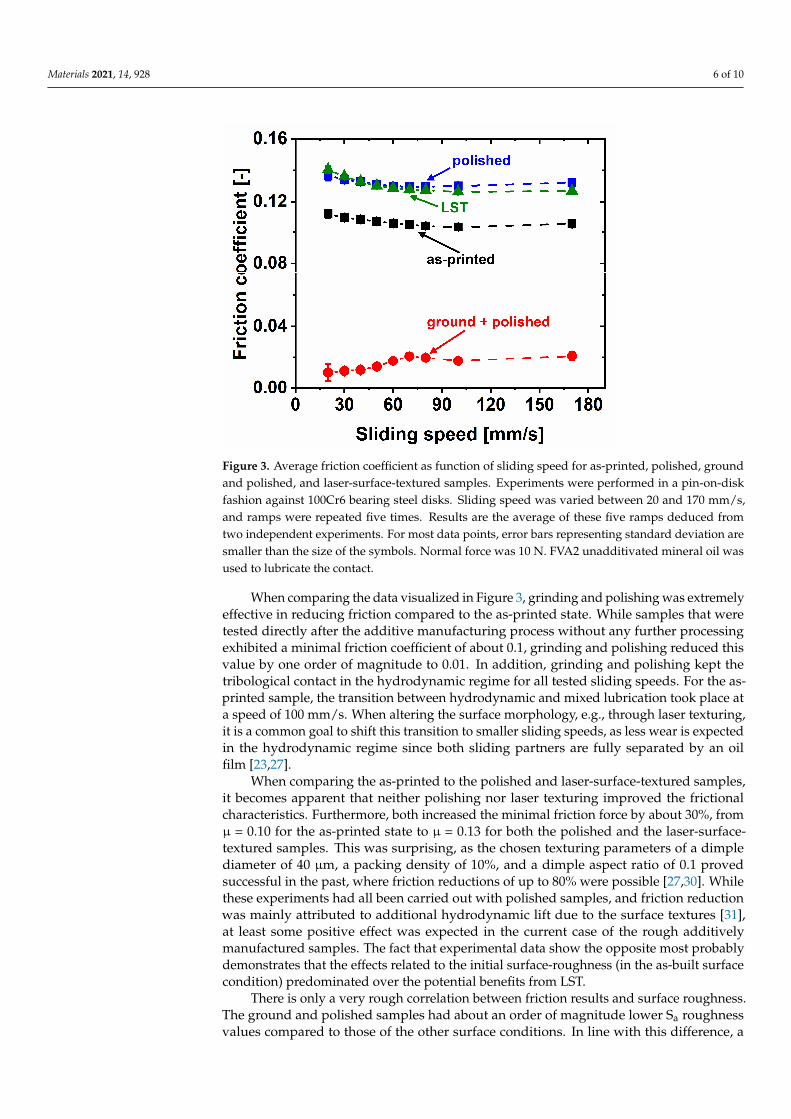
Figure 4. Optical micrographs for samples after tribological experiments. (a) As-printed, (b) pol-ished, (c) ground and polished, and (d) laser-surface-textured H13 steel samples initially prepared by SLM. Magnification for each image was chosen as such to best represent the samples.
These images second the gravimetrical results. Only very few signs of wear are visi-ble, with the exception of the ground and polished sample (Figure 4c). Here, scratches can be seen, but the material loss associated with them was still too small to make a detectable gravimetrical difference. More detailed wear studies are needed before a conclusive state-ment about this important aspect of tribological performance will be possible.
4. Conclusions The tribological properties of additively manufactured H13 steel samples in four dif-
ferent surface conditions were tested. Samples were investigated in as-printed, solely pol-ished, ground and polished, or laser-surface-textured states, the latter being characterized by round dimples of 40 µm in diameter. Tribological experiments were run against bear-ing steel disks in a unidirectional pin-on-disk tribometer. The contact was lubricated with a base oil without additives. The sliding speed was varied between 20 and 170 mm/s to measure the part of the Stribeck curve where the transition between mixed and hydrody-namic lubrication was expected. Tribological data demonstrate that grinding and polish-ing the as-printed surfaces to a mirror finish of Sa = 0.15 µm lowered the friction coefficient by about one order of magnitude compared to the as-printed samples. The ground-and-polished samples were the only ones, where hydrodynamic lubrication was present for all sliding speeds. The minimal friction coefficient for the as-printed state was 0.1, and 0.01 for the ground-and-polished surface state. Contrary to expectation, polishing and la-ser surface texturing both increased the minimal friction coefficient to about 0.13. There was no clear correlation of these results with surface roughness. Polishing did not alter the Sa value compared to the as-printed surface, while laser texturing reduced it. Wear was below the detection limit of the employed gravimetrical method. In the optical mi-crographs, only few signs of wear events are observed. Detailed fluid dynamics modeling is most probably required to fully understand these results. However, they highlight how
Figure 4. Optical micrographs for samples after tribological experiments. (a) As-printed, (b) polished,(c) ground and polished, and (d) laser-surface-textured H13 steel samples initially prepared by SLM.Magnification for each image was chosen as such to best represent the samples.
These images second the gravimetrical results. Only very few signs of wear are visible,with the exception of the ground and polished sample (Figure 4c). Here, scratches can beseen, but the material loss associated with them was still too small to make a detectablegravimetrical difference. More detailed wear studies are needed before a conclusivestatement about this important aspect of tribological performance will be possible.
4. Conclusions
The tribological properties of additively manufactured H13 steel samples in fourdifferent surface conditions were tested. Samples were investigated in as-printed, solelypolished, ground and polished, or laser-surface-textured states, the latter being character-ized by round dimples of 40 µm in diameter. Tribological experiments were run againstbearing steel disks in a unidirectional pin-on-disk tribometer. The contact was lubricatedwith a base oil without additives. The sliding speed was varied between 20 and 170 mm/sto measure the part of the Stribeck curve where the transition between mixed and hydrody-namic lubrication was expected. Tribological data demonstrate that grinding and polishingthe as-printed surfaces to a mirror finish of Sa = 0.15 µm lowered the friction coefficientby about one order of magnitude compared to the as-printed samples. The ground-and-polished samples were the only ones, where hydrodynamic lubrication was present forall sliding speeds. The minimal friction coefficient for the as-printed state was 0.1, and0.01 for the ground-and-polished surface state. Contrary to expectation, polishing and lasersurface texturing both increased the minimal friction coefficient to about 0.13. There wasno clear correlation of these results with surface roughness. Polishing did not alter the Savalue compared to the as-printed surface, while laser texturing reduced it. Wear was belowthe detection limit of the employed gravimetrical method. In the optical micrographs,only few signs of wear events are observed. Detailed fluid dynamics modeling is mostprobably required to fully understand these results. However, they highlight how strongthe effect of post-processing can be. A much better understanding of these processes onthe tribological performance of additively manufactured parts used in tribological contactsneeds to be established.
Materials 2021, 14, 928 9 of 10
Author Contributions: Conceptualization, C.G. and T.N.; methodology, E.G., M.K., and M.V.;writing—original-draft preparation, C.G. and E.G.; writing—review and editing, C.G. and T.N.All authors have read and agreed to the published version of the manuscript.
Funding: C.G. acknowledges partial funding by the European Research Council (ERC) under grantno. 771237, TriboKey. We acknowledge support by the KIT-Publication Fund of the KarlsruheInstitute of Technology (KIT).
Data Availability Statement: Raw data and images are available from the corresponding authorupon request and have been published under https://doi.org/10.5445/IR/1000129689.
Conflicts of Interest: The authors declare no conflict of interest. The funders had no role in the designof the study; in the collection, analyses, or interpretation of data; in the writing of the manuscript, orin the decision to publish the results.
References1. Bajaj, P.; Hariharan, A.; Kini, A.; Kürnsteiner, P.; Raabe, D.; Jägle, E.A. Steels in additive manufacturing: A review of their
microstructure and properties. Mater. Sci. Eng. A 2020, 772, 138633. [CrossRef]2. Cao, J.; Brinksmeier, E.; Fu, M.; Gao, R.X.; Liang, B.; Merklein, M.; Schmidt, M.; Yanagimoto, J. Manufacturing of advanced smart
tooling for metal forming. Cirp Ann. 2019, 68, 605–628. [CrossRef]3. DebRoy, T.; Wei, H.L.; Zuback, J.S.; Mukherjee, T.; Elmer, J.W.; Milewski, J.O.; Beese, A.M.; Wilson-Heid, A.; De, A.; Zhang,
W. Additive manufacturing of metallic components—Process, structure and properties. Prog. Mater. Sci. 2018, 92, 112–224.[CrossRef]
4. Holmberg, K.; Erdemir, A. Influence of tribology on global energy consumption, costs and emissions. Friction 2017, 5, 263–284.[CrossRef]
5. Strano, G.; Hao, L.; Everson, R.M.; Evans, K.E. Surface roughness analysis, modelling and prediction in selective laser melting. J.Mater. Process. Technol. 2013, 213, 589–597. [CrossRef]
6. Yasa, E.; Kruth, J.P. Microstructural investigation of Selective Laser Melting 316L stainless steel parts exposed to laser remelting.Procedia Eng. 2011, 19, 389–395. [CrossRef]
7. Qiu, C.; Panwisawas, C.; Ward, M.; Basoalto, H.C.; Brooks, J.W.; Attallah, M.M. On the role of melt flow into the surface structureand porosity development during selective laser melting. Acta Mater. 2015, 96, 72–79. [CrossRef]
8. Rathod, H.J.; Nagaraju, T.; Prashanth, K.G.; Ramamurty, U. Tribological properties of selective laser melted Al12Si alloy. Tribol.Int. 2019, 137, 94–101. [CrossRef]
9. Zhu, Y.; Zou, J.; Chen, X.; Yang, H. Tribology of selective laser melting processed parts: Stainless steel 316L under lubricatedconditions. Wear 2016, 350–351, 46–55. [CrossRef]
10. Chandramohan, P.; Bhero, S.; Obadele, B.A.; Olubambi, P.A. Laser additive manufactured Ti–6Al–4V alloy: Tribology andcorrosion studies. Int. J. Adv. Manuf. Technol. 2017, 92, 3051–3061. [CrossRef]
11. Zhu, Y.; Lin, G.; Khonsari, M.M.; Zhang, J.; Yang, H. Material characterization and lubricating behaviors of porous stainless steelfabricated by selective laser melting. J. Mater. Process. Technol. 2018, 262, 41–52. [CrossRef]
12. Yan, X.; Chen, C.; Bolot, R.; Ma, W.; Deng, C.; Wang, J.; Ren, Z.; Liao, H.; Liu, M. Improvement of tribological performance bymicro-arc oxidation treatment on selective laser melting Ti6Al4V alloy. Mater. Res. Express 2019, 6, 096509. [CrossRef]
13. Li, H.; Ramezani, M.; Li, M.; Ma, C.; Wang, J. Tribological performance of selective laser melted 316L stainless steel. Tribol. Int.2018, 128, 121–129. [CrossRef]
14. Hao, J.; Hu, F.; Le, X.; Liu, H.; Yang, H.; Han, J. Microstructure and high-temperature wear behaviour of Inconel 625 multi-layercladding prepared on H13 mould steel by a hybrid additive manufacturing method. J. Mater. Process. Technol. 2021, 291, 117036.[CrossRef]
15. King, D.; Middendorf, J.; Cissel, K.; Key, T.; Carney, C. Selective laser melting for the preparation of an ultra-high temperatureceramic coating. Ceram. Int. 2019, 45, 2466–2473. [CrossRef]
16. Lee, J.; Terner, M.; Copin, E.; Lours, P.; Hong, H.-U. A novel approach to the production of NiCrAlY bond coat onto IN625superalloy by selective laser melting. Addit. Manuf. 2020, 31, 100998. [CrossRef]
17. Casati, R.; Coduri, M.; Lecis, N.; Andrianopoli, C.; Vedani, M. Microstructure and mechanical behavior of hot-work tool steelsprocessed by Selective Laser Melting. Mater. Charact. 2018, 137, 50–57. [CrossRef]
18. Geenen, K.; Röttger, A.; Feld, F.; Theisen, W. Microstructure, mechanical, and tribological properties of M3:2 high-speed steelprocessed by selective laser melting, hot-isostatic pressing, and casting. Addit. Manuf. 2019, 28, 585–599. [CrossRef]
19. Stribeck, R. Die Wesentlichen Eigenschaften der Gleit- und Rollenlager. Z. Ver. Deut. Ing. 1902, 46.20. Iquebal, A.S.; Sagapuram, D.; Bukkapatnam, S.T.S. Surface plastic flow in polishing of rough surfaces. Sci. Rep. 2019, 9, 10617.
[CrossRef]21. Jones, M.R.; Nation, B.L.; Wellington-Johnson, J.A.; Curry, J.F.; Kustas, A.B.; Lu, P.; Chandross, M.; Argibay, N. Evidence of
Inverse Hall-Petch Behavior and Low Friction and Wear in High Entropy Alloys. Sci. Rep. 2020, 10, 10151. [CrossRef] [PubMed]
Materials 2021, 14, 928 10 of 10
22. Konovalov, S.; Osintsev, K.; Golubeva, A.; Smelov, V.; Ivanov, Y.; Chen, X.; Komissarova, I. Surface modification of Ti-based alloyby selective laser melting of Ni-based superalloy powder. J. Mater. Res. Technol. 2020, 9, 8796–8807. [CrossRef]
23. Etsion, I. State of the Art in Laser Surface Texturing; Tsinghua University Press: Beijing, China, 2009; pp. 761–762.24. Gachot, C.; Rosenkranz, A.; Hsu, S.M.; Costa, H.L. A critical assessment of surface texturing for friction and wear improvement.
Wear 2017, 372, 21–41. [CrossRef]25. Wang, L. Use of structured surfaces for friction and wear control on bearing surfaces. Surf. Topogr. Metrol. Prop. 2014, 2, 043001.
[CrossRef]26. Breidenstein, B.; Brenne, F.; Wu, L.; Niendorf, T.; Denkena, B. Effect of Post-Process Machining on Surface Properties of Additively
Manufactured H13 Tool Steel. HTM J. Heat Treat. Mater. 2018, 73, 173–186. [CrossRef]27. Braun, D.; Greiner, C.; Schneider, J.; Gumbsch, P. Efficiency of laser surface texturing in the reduction of friction under mixed
lubrication. Tribol. Int. 2014, 77, 142–147. [CrossRef]28. Schneider, J.; Braun, D.; Greiner, C. Laser textured surfaces for mixed lubrication: Influence of aspect ratio, textured area and
dimple arrangement. Lubricants 2017, 5, 32. [CrossRef]29. Snyder, J.C.; Thole, K.A. Understanding Laser Powder Bed Fusion Surface Roughness. J. Manuf. Sci. Eng. 2020, 142, 7. [CrossRef]30. Greiner, C.; Merz, T.; Braun, D.; Codrignani, A.; Magagnato, F. Optimum dimple diameter for friction reduction with laser surface
texturing: The effect of velocity gradient. Surf. Topogr. Metrol. Prop. 2015, 3, 044001. [CrossRef]31. Codrignani, A.; Frohnapfel, B.; Magagnato, F.; Schreiber, P.; Schneider, J.; Gumbsch, P. Numerical and experimental investigation
of texture shape and position in the macroscopic contact. Tribol. Int. 2018, 122, 46–57. [CrossRef]32. Blau, P.J. The significance and use of the friction coefficient. Tribol. Int. 2001, 34, 585–591. [CrossRef]33. Zhang, Z.F.; Zhang, L.C.; Mai, Y.W. Particle effects on friction and wear of aluminium matrix composites. J. Mater. Sci. 1995, 30,
5999–6004. [CrossRef]34. Gropper, D.; Wang, L.; Harvey, T.J. Hydrodynamic lubrication of textured surfaces: A review of modeling techniques and key
findings. Tribol. Int. 2016, 94, 509–529. [CrossRef]35. Arghir, M.; Roucou, N.; Helene, M.; Frene, J. Theoretical Analysis of the Incompressible Laminar Flow in a Macro-Roughness
Cell. J. Tribol. 2003, 125, 309–318. [CrossRef]36. Qiu, Y.; Khonsari, M.M. Performance Analysis of Full-Film Textured Surfaces With Consideration of Roughness Effects. J. Tribol.
2011, 133, 021704. [CrossRef]37. Emmens, W.C. Tribology of Flat Contacts and Its Application in Deep Drawing. Ph.D. Thesis, University of Twente, Enschede,
The Netherlands, 1997.38. Patir, N.; Cheng, H.S. An Average Flow Model for Determining Effects of Three-Dimensional Roughness on Partial Hydrodynamic
Lubrication. J. Tribol. 1978, 100, 12–17. [CrossRef]39. Patir, N.; Cheng, H.S. Application of average flow model to lubrication between rough sliding surfaces. J. Lubr. Technol. 1979, 101,
220–229. [CrossRef]40. Tripp, J.H. Surface roughness effects in hydrodynamic lubrication: The flow factor method. J. Lubr. Technol. 1983, 105, 458–463.
[CrossRef]41. Bowden, F.P.; Tabor, D. The Friction and Lubrication of Solids; Clarendon Press: Oxford, UK, 1950.42. Eder, S.J.; Grutzmacher, P.G.; Ripoll, M.R.; Dini, D.; Gachot, C. Effect of Temperature on the Deformation Behavior of Copper
Nickel Alloys under Sliding. Materials 2021, 14, 16.43. Beilby, G.T. Surface flow in crystalline solids under mechanical disturbance. Proc. R. Soc. Lond. 1904, 72, 218–225.


![Anna-Lisa Vollmer arXiv:2108.11608v1 [cs.RO] 26 Aug 2021](https://static.fdocuments.us/doc/165x107/616f48bc30d52656826e5378/anna-lisa-vollmer-arxiv210811608v1-csro-26-aug-2021.jpg)