VME Bus Vinay Shet. Introduction VME - Versa Module Europa Flexible, open-ended bus system using the...
35
VME Bus Vinay Shet
-
Upload
alvin-skanes -
Category
Documents
-
view
220 -
download
0
Transcript of VME Bus Vinay Shet. Introduction VME - Versa Module Europa Flexible, open-ended bus system using the...

VME Bus
Vinay Shet

Introduction
• VME - Versa Module Europa• Flexible, open-ended bus system using the
Eurocard Standard• Introduced by Motorola, Mostek and Signetics
in 1981• It was intended to be a flexible environment,
supporting a variety of computing intensive tasks.
• Defined in IEEE 1014-1987 standard

Introduction
• In 1981, Motorola decided to second source the MC68000 microprocessor chip
• Motorola proposed the use of VERSA bus backplane
• However, the others rejected this proposal saying that the VERSA bus board size was much too large
• In response, Motorola proposed that they use the (much smaller) Eurocard board instead
Introduction
• VERSA bus electrical specifications and Eurocard mechanical specifications

VME bus features
• Master / slave architecture
Functional unit
called MASTERFunctional unit
called SLAVE
Data
• Since multiple Masters can reside on the bus, it is a MULTIPROCESSING bus
• Can take from 1 to 21 Masters
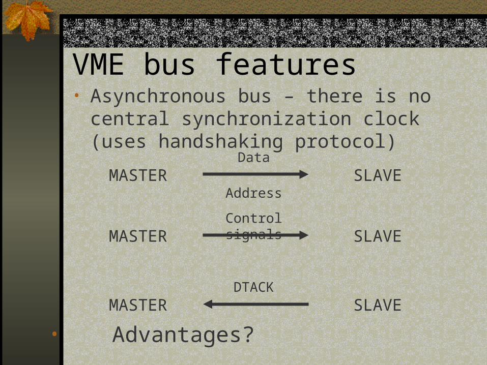
VME bus features• Asynchronous bus – there is no central
synchronization clock (uses handshaking protocol)
MASTER SLAVEData
Address
MASTER SLAVEControl signals
MASTER SLAVEDTACK
• Advantages?
VME bus features
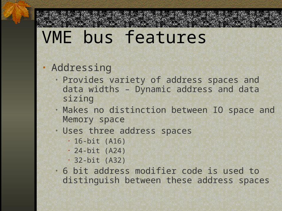
• Addressing• Provides variety of address spaces and data
widths – Dynamic address and data sizing• Makes no distinction between IO space and
Memory space• Uses three address spaces
• 16-bit (A16)• 24-bit (A24)• 32-bit (A32)
• 6 bit address modifier code is used to distinguish between these address spaces

VME bus features
• Data Transfer• Provides variety of data widths – Dynamic data sizing• Data transfer sizes can be
• 8-bit• 16-bit• 32-bit
• Data transfer cycles can be Single Cycle or Block Transfer• Single Cycle – Address is sent with each data transfer • Block Transfer – one address is sent with multiple data
transfers

VME bus features
• Data Transfer Cycles• Single cycles – D8(O), D8(EO), D16, D32 and
MD32• Block Transfer – BLT, MBLT, A40BLT
• Mixing different address and data widths• You can use different address and data widths
based on the application • Common examples
• A16/D8(O) – simple IO boards• A32/D32 – high performance modules

VME bus features
• Data Transfer Speed
Topology Bus Cycle Maximum Speed
VMEbusIEEE-1014
BLT 40 Mbyte/sec
VME64 MBLT 80 Mbyte/sec
VME64x 2eVME 160 Mbyte/sec
VME320 2eSST320 - 500+Mbyte/sec

VME bus features
• Byte Ordering• VME bus does not specify byte ordering• Most devices use the Motorola model which is big
endian, but the Digital model is little endian• Two models are provided to accomplish byte
swapping• VMS bus adapter• Software interfaces

VME bus features
• Interrupts Vectors• VME bus interrupt vectors range from 0x00
to 0xFF, inclusive.• The bus adapter consumes some of these
adapters and area not available to the device drivers
• Interrupt Priorities• Seven interrupt priorities (IRQ1 through
IRQ 7 – IRQ7 highest priority)

VME bus features
• Bus Arbitration• With single master, life is easy – when system
boots, the master asks for the bus, gets it and keeps it.
• VME provides 4 separate bus request levels • Two or more masters can request the bus at the
same time on the same request level• If multiple requests on same level then proximity to
slot one is used to determine who will get the bus

VME bus features
• Bus Arbitration• E.g M(3) and M(7) request on level 1 at
same time M(3) will get the bus first• M(7) has to wait until M(3) has finished and
then assuming no one form slot 1 – 6 requests then M(7) gets bus
• Arbitration is done by the System Controller – always resides in slot 1

VME bus features
• Bus Arbitration• Arbitration can be set up in
• Priority mode• Round robin mode• Single level mode
• Releasing the bus• RWD – Release when done• ROR – Release on request (usually
implemented in H/W hence faster)

VME bus features
• Bus Arbitration• Fairness
• In heavily loaded system, first four boards can hog the bus and starve the rest.
• To prevent this – bus requesters are programmed to request bus only when bus request lines are not asserted – Fairness
• This ensures that all boards – even in a heavily loaded system – eventually get the bus

VME bus features
• Live insertion capability• Electronic module can be removed and inserted in
the system when the power is on• Also known as Hot Swap• Typical Board de-allocation Process
• System admin software disables new connections to board’s device driver
• System waits for all connections to terminate or forces existing connections to terminate

VME bus features
• VMEbus System Controller• Resides in slot 1• Bus Arbitration• Provides 16 MHz system clock (SYSCLK)• Provides the interrupt acknowledge (IACK) daisy
chain driver
• VMEbus Daisy Chains• Five daisy chain signals on VME bus – four used for
bus arbitration and one for interrupt acknowledge• Bus arbitration done using 4 bus request lines and 4
bus grant in/out lines

VME bus features
• VME bus standard specifies two board sizes • 3U – 100mm x 160mm – one connector P1• 6U – 233.5mm x 160mm – two connectors
P1, P2
•VME bus P2/J2 user defined pins

VME bus features
• Summary of features
Item Specification Notes
Architecture Master/slave
Transfer MechanismAsynchronous, with both multiplexed and non-
multiplexed bus cycles.There is no central synchronization clock.
Addressing Range 16, 24, 32, 40 or 64-bit Address path width selected dynamically.
Data Path Width8, 16, 24, 32 or 64-bit
Data path width selected dynamically.
Data Transfer Rate 0 - 500+ Mbyte/sec See Table

VME bus features
• Summary of features
Interrupts 7 levelsPriority interrupt system with 8, 16 or 32-bit STATUS/ID (interrupt vector).
Multiprocessing Capability
1 - 21 processorsFlexible bus arbitration with true peer-to-peer multiprocessing.
Item Specification Notes
Architecture Master/slave
Transfer MechanismAsynchronous, with both multiplexed and non-
multiplexed bus cycles.There is no central synchronization clock.
Addressing Range 16, 24, 32, 40 or 64-bit Address path width selected dynamically.
VME bus features
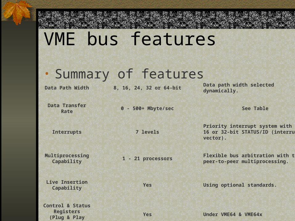
• Summary of featuresData Path Width 8, 16, 24, 32 or 64-bit Data path width selected dynamically.
Data Transfer Rate 0 - 500+ Mbyte/sec See Table
Interrupts 7 levelsPriority interrupt system with 8, 16 or 32-bit STATUS/ID (interrupt vector).
Multiprocessing Capability
1 - 21 processorsFlexible bus arbitration with true peer-to-peer multiprocessing.
Live Insertion Capability
Yes Using optional standards.
Control & Status Registers
(Plug & Play Support)Yes Under VME64 & VME64x

VME bus features
• Summary of features
Mechanical Standard3U single-height Eurocard6U double-height Eurocard9U (optional standard)
160 x 100 mm Eurocard160 x 233 mm Eurocard367 x 400 mm Eurocard
User Defined I/O YesThrough the Front Paneland P2/J2 User Defined Pins
Conduction Cooled Version
(Military)Yes Under IEEE 1101.2
Maximum Number ofCard Slots in
Backplane21
The number of cards is limited by how many boards, located on 0.8" centers, can be placed into a 19" rack panel.

Original VME bus spec
• MASTER/SLAVE architecture• Asynchronous bus• Variable speed handshaking protocol• Non-multiplexed bus• Addressing range between 16 and 32 bits• Data path widths of between 8 and 32 bits• Bandwidths of up to 40 Mbyte/sec• Multiprocessing capability• Interrupt capability

Original VME bus spec
• Wide variety of mechanical hardware based on the IEEE 1101 standard
• Up to 21 card slots can be used in a single backplane
VME64 features
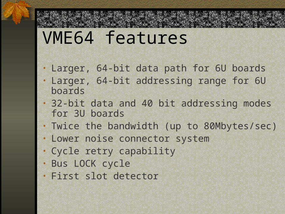
• Larger, 64-bit data path for 6U boards• Larger, 64-bit addressing range for 6U boards• 32-bit data and 40 bit addressing modes for
3U boards• Twice the bandwidth (up to 80Mbytes/sec)• Lower noise connector system• Cycle retry capability• Bus LOCK cycle• First slot detector
VME64 features
• Automatic plug-n-play features• Configuration ROM / CSR capability• Re-definition of SERCLK and SERDAT
pins

VME64x features
• A new 160 pin connector family• A 95 pin P0/J0 connector• 3.3 V power supply pins• More +5 VDC power supply pins • Geographical addressing • Higher bandwidth bus cycles• 141 more user defined pins• Rear plug-in units • Live insertion / hot swap capability• Injector / ejector locking handles

VME bus software
• VME bus has the lasrgest software base of any computer architecture
• There are 103 known commercial operating systems running on VME bus – other propreitary Operating systems are also known to exist

VME bus architecture
• VME architecture is usually described interms of its functional modules • See table 3

VME bus architecture
• Various functional units communicate with each other over five sub-buses • See table 4

VME bus architecture
• Bus cycles are impressed upon the sub-buses
• The standard VME bus cycle is the READ/WRITE cycle.• See table 5

Multi Crate operation
• Max size of VME bus backplanes is 21 slots
• If more slots are needed there are two ways of achieving this• Use a VME bus-to-VME bus bridge cardset• Use a pair of “reflective memory” card

Applications
• Industrial Control• Military• Aerospace• Transportation• Telecom• Simulation• Medical• High energy physics• General business

Links
• IEEE 1014-1987 standard specification• www.vita.com/vmefaq• www.hitex.com/automation/FAQ/vmefaq