Scan this to subscribe Engineers’ Guide to VME, VPX &...
36
www.eecatalog.com/vme Engineers’ Guide to VME, VPX & VXS Changes at VITA Gold Sponsors The Future of VITA-based SFF and Mezzanine Boards Carriers Provide Versatile Design Options for VITA-based Systems The Smaller VITA 73 Small Form Factor and MicroATR Chassis Scan this QR code to subscribe
Transcript of Scan this to subscribe Engineers’ Guide to VME, VPX &...
www.eecatalog.com/vme
Engineers’ Guide to VME, VPX & VXS
Changes at VITA
Gold Sponsors
The Future of VITA-based SFF and Mezzanine Boards
Carriers Provide Versatile Design Options for VITA-based Systems
The Smaller VITA 73 Small Form Factor and MicroATR Chassis
Scan this QR code to subscribe
Elma Electronic Inc. • 510.656.3400 • [email protected] • www.elma.com
ELMA
Embe
dded
Com
putin
g
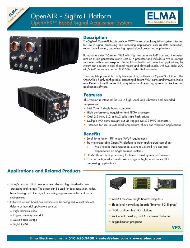
OpenATR - SigPro1 PlatformOpenVPX™ Based Signal Acquisition System
FeaturesThis version is intended for use in high shock and vibration and extended temperature. • Intel Core i7 single board computer• High performance acquisition and FPGA processor•Dual 2.5-inch, SLC or MLC solid state flash drives• Multiple I/O ports brought out via rugged MIL-C-38999 connectors• Intended for use in extended temperature, shock and vibration applications
DescriptionThe SigPro1 OpenATR box is an OpenVPX™ based signal acquisition system intended for use in signal processing and recording applications such as data acquisition, radar, beamforming, and other high speed signal processing applications.
Based on a Virtex™-6 series FPGA with high performance A/D front end, the system runs on a 2nd generation Intel® Core i7™ processor and includes a two-TB storage subsystem with room to expand. For high bandwidth data collection applications, the system can operate in dual channel record and playback mode, with two 16-bit 200 MS/s A/D converters and an 800 MS/s 16-bit D/A converter.
The complete payload is a truly interoperable, multi-vendor OpenVPX platform. The OpenATR is highly configurable, accepting different FPGA cards and firmware. It also runs Pentek’s Talon® series data acquisition and recording system architecture and application software.
• Today’s mission critical defense systems demand high bandwidth data processing and storage. The system can be used for data acquisition, radar, beam forming and other signal processing applications in the most harsh environments.• Other chassis and board combinations can be configured to meet different defense or industrial applications such as: o High definition video o Engine control systems data o Mission data storage o SigInt, C4ISR
Applications and Related Products
• Intel & Freescale Single Board Computers
• Blade level networking boards (Ethernet, PCI Express)
• FPGA configurable I/O solutions
• Rackmount, desktop, and ATR chassis platforms
• Ruggedization programs
VPX
Benefits• Small form factor (SFF) meets SWaP requirements• Truly interoperable OpenVPX platform is open architecture compliant o Multi-vendor implementation minimizes overall risk and user dependence on single sourced systems• FPGA offloads I/O processing for faster overall system performance• Can be configured to meet a wide range of high performance I/O processing applications
You need it right.You want Dawn.
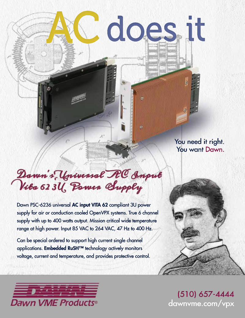
Dawn PSC-6236 universal AC input VITA 62 compliant 3U power
supply for air or conduction cooled OpenVPX systems. True 6 channel
supply with up to 400 watts output. Mission critical wide temperature
range at high power. Input 85 VAC to 264 VAC, 47 Hz to 400 Hz.
Can be special ordered to support high current single channel
applications. Embedded RuSH™ technology actively monitors
voltage, current and temperature, and provides protective control.
(510) 657-4444dawnvme.com/vpx
does itACACAC
2 Engineers’ Guide to VME, VPX & VXS 2014
www.eecatalog.com/vme
Vice President & PublisherClair Bright [email protected](415) 255-0390 ext. 15
EditorialVice President/Chief Content OfficerJohn Blyler [email protected](503) 614-1082
Editor-in-ChiefChris A. Ciufo [email protected]
Managing EditorCheryl Coupé [email protected]
Creative/ProductionProduction Manager Spryte Heithecker
Graphic DesignersNicky JacobsonJacob Ewing
Media Coordinator Yishian Yao
Production Assistant Jozee Adamson
Senior Web DeveloperSlava DotsenkoMariam Moattari
Advertising/Reprint SalesVice President & Publisher Embedded Electronics Media GroupClair Bright [email protected](415) 255-0390 ext. 15
Sales ManagerMichael Cloward [email protected] (415) 255-0390 x17
Marketing/CirculationJenna Johnson
To Subscribewww.extensionmedia.com/free
Extension Media, LLCCorporate OfficePresident and PublisherVince [email protected]
Vice President, SalesEmbedded Electronics Media GroupClair [email protected]
Vice President, Chief Content OfficerJohn [email protected]
Vice President, Business DevelopmentMelissa [email protected]
Special Thanks to Our Sponsors
The Engineers’ Guide to VME is published by Extension Media LLC. Extension Media makes no warranty for the use of its products and assumes no responsibility for any errors which may appear in this Catalog nor does it make a commitment to update the information contained herein. The Engineers’ Guide to VME is Copyright ®2014 Extension Media LLC. No information in this Catalog may be reproduced without expressed written permission from Extension Media @ 1786 18th Street, San Francisco, CA 94107-2343.All registered trademarks and trademarks included in this Catalog are held by their respective companies. Every attempt was made to include all trademarks and registered trademarks where indicated by their companies.
Engineers’ Guide to VME, VPX & VXS 2014Welcome to the Engineers’
Guide to VME, VPX & VXS 2014
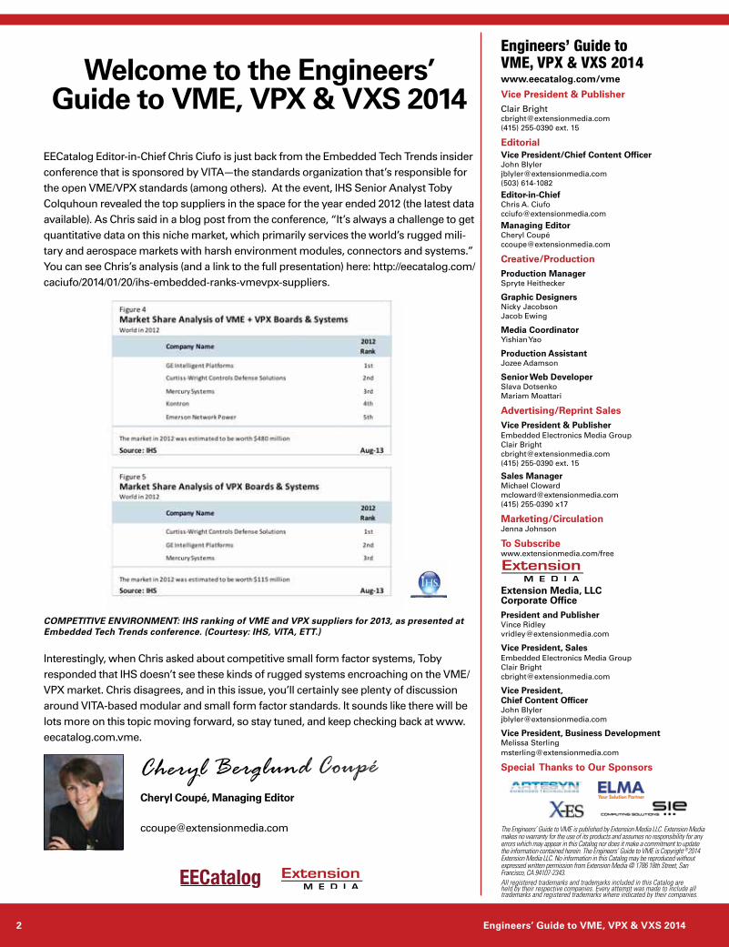
EECatalog Editor-in-Chief Chris Ciufo is just back from the Embedded Tech Trends insider conference that is sponsored by VITA—the standards organization that’s responsible for the open VME/VPX standards (among others). At the event, IHS Senior Analyst Toby Colquhoun revealed the top suppliers in the space for the year ended 2012 (the latest data available). As Chris said in a blog post from the conference, “It’s always a challenge to get quantitative data on this niche market, which primarily services the world’s rugged mili-tary and aerospace markets with harsh environment modules, connectors and systems.” You can see Chris’s analysis (and a link to the full presentation) here: http://eecatalog.com/caciufo/2014/01/20/ihs-embedded-ranks-vmevpx-suppliers.
Interestingly, when Chris asked about competitive small form factor systems, Toby responded that IHS doesn’t see these kinds of rugged systems encroaching on the VME/VPX market. Chris disagrees, and in this issue, you’ll certainly see plenty of discussion around VITA-based modular and small form factor standards. It sounds like there will be lots more on this topic moving forward, so stay tuned, and keep checking back at www.eecatalog.com.vme.
Cheryl Coupé, Managing Editor
COMPETITIVE ENVIRONMENT: IHS ranking of VME and VPX suppliers for 2013, as presented at Embedded Tech Trends conference. (Courtesy: IHS, VITA, ETT.)
Cheryl Berglund Coupé
www.eecatalog.com/vme 3
Engineers’ Guide to VME, VPX & VXS 2014
4 Engineers’ Guide to VME, VPX & VXS 2014
Contents
Changes at VITABy Jerry Gipper, VITA .................................................................................................................................................................................6
The Future of VITA-based SFF and Mezzanine BoardsBy Cheryl Coupé, Managing Editor ............................................................................................................................................................ 8
Modern Technology in a Traditional Form FactorBy Ákos Csilling, CES - Creative Electronic Systems SA.......................................................................................................................... 11
The Smaller VITA 73 Small Form Factor and MicroATR ChassisBy Marc Benjamin Gross, CEO Sales and Marketing, PCI Systems Inc. ................................................................................................. 13
Multiple Processors in High-Performance Embedded Computing: “Only Connect”By Peter Thompson, GE Intelligent Platforms .......................................................................................................................................... 16
DO-178C: Accommodating the Evolution of Software ProcessesBy Bill StClair, LDRA ............................................................................................................................................................................... 19
Carriers Provide Versatile Design Options for VITA-based SystemsBy Justin Moll, VadaTech ....................................................................................................................................................................... 22
Product services
Hardware
BackplanesSIE Computing SolutionsVPX Backplanes ..................................................................... 24
CPU or Single Board ComputersArtesyn Embedded TechnologiesMVME8100 Freescale P5020 QorIQ processor VME Board ................................................ 25MVME2500 .......................................................................... 25
CSP Inc.3220Q OpenVPX Intel® Xeon® .......................................... 263130T4 Freescale QorIQ™ T4160/T4240 ............................ 27
Pro-Dex, OMS MAXv VME/VME64 Bus Motion Control ............................. 28
Data Aquisition Pentek, Inc.Model 52730: 1 GHz A/D,1 GHz D/A with Virtex-7 FPGA ............................................. 29
EnclosuresSIE Computing Solutions717 Series Air-Over Conduction Cooled ATR Enclosures ......................................................... 30“Mupac” 760 Small Form Factor Series ............................... 31
Software
DevelopmentTeledyne LeCroyTeledyne LeCroy’s PCI Express® Protocol Analysis and Test Tools........................................... 32
Elma Electronic Inc. • 510.656.3400 • [email protected] • www.elma.com
ELMA
Embe
dded
Com
putin
g
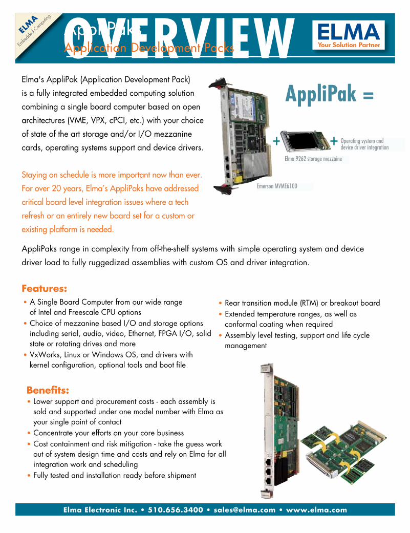
OVERVIEWElma's AppliPak (Application Development Pack)
is a fully integrated embedded computing solution
combining a single board computer based on open
architectures (VME, VPX, cPCI, etc.) with your choice
of state of the art storage and/or I/O mezzanine
cards, operating systems support and device drivers.
Staying on schedule is more important now than ever.
For over 20 years, Elma’s AppliPaks have addressed
critical board level integration issues where a tech
refresh or an entirely new board set for a custom or
existing platform is needed.
• A Single Board Computer from our wide range of Intel and Freescale CPU options • Choice of mezzanine based I/O and storage options including serial, audio, video, Ethernet, FPGA I/O, solid state or rotating drives and more• VxWorks, Linux or Windows OS, and drivers with kernel configuration, optional tools and boot file
Features:• Rear transition module (RTM) or breakout board • Extended temperature ranges, as well as conformal coating when required• Assembly level testing, support and life cycle management
AppliPaks range in complexity from off-the-shelf systems with simple operating system and device
driver load to fully ruggedized assemblies with custom OS and driver integration.
Emerson MVME6100
Elma 9262 storage mezzaine
Operating system anddevice driver integration
AppliPak =
AppliPaks Application Development Packs
• Lower support and procurement costs - each assembly is sold and supported under one model number with Elma as your single point of contact • Concentrate your efforts on your core business • Cost containment and risk mitigation - take the guess work out of system design time and costs and rely on Elma for all integration work and scheduling• Fully tested and installation ready before shipment
Benefits:
6 Engineers’ Guide to VME, VPX & VXS 2014
Special Feature
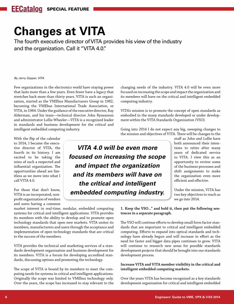
Few organizations in the electronics world have staying power that lasts more than a few years. Even fewer have a legacy that stretches back more than thirty years. VITA is such an organi-zation, started as the VMEbus Manufacturers Group in 1982, becoming the VMEbus International Trade Association, or VITA, in 1984. Under the guidance of the executive director, Ray Alderman, and his team—technical director John Rynearson and administrator Lollie Wheeler—VITA is a recognized leader in standards and business development for the critical and intelligent embedded computing industry.
With the flip of the calendar to 2014, I became the execu-tive director of VITA, the fourth in its history. I am excited to be taking the reins of such a respected and influential organization. The opportunities ahead are lim-itless as we move into what I call VITA 4.0.
For those that don’t know, VITA is an incorporated, non-profit organization of vendors and users having a common market interest in real-time, modular, embedded computing systems for critical and intelligent applications. VITA provides its members with the ability to develop and to promote open technology standards that open new markets. VITA unites its members, manufacturers and users through the acceptance and implementation of open technology standards that are critical to the success of the members.
VITA provides the technical and marketing services of a stan-dards development organization and business development for its members. VITA is a forum for developing accredited stan-dards, discussing options and promoting the technology.
The scope of VITA is bound by its members to meet the com-puting needs for systems in critical and intelligent applications. Originally the scope was limited to VMEbus technology only. Over the years, the scope has increased to stay relevant to the
changing needs of the industry. VITA 4.0 will be even more focused on increasing the scope and impact the organization and its members will have on the critical and intelligent embedded computing industry.
VITA’s mission is to promote the concept of open standards as embodied in the many standards developed or under develop-ment within the VITA Standards Organization (VSO).
Going into 2014 I do not expect any big, sweeping changes to the mission and objectives of VITA. There will be changes to the
staff as John and Lollie have both announced their inten-tions to retire after many years of dedicated service to VITA. I view this as an opportunity to review some of the business processes and shift assignments to make the organization even more efficient and effective.
Under the mission, VITA has two key objectives to reach as we go into 2014.
1. Keep the VSO...” and bold it, then put the following sen-tences in a separate paragraph.
The VSO will continue efforts to develop small form factor stan-dards that are important to critical and intelligent embedded computing. Efforts to expand into optical standards and tech-nology have already begun and will increase in effort as the need for faster and bigger data pipes continues to grow. VITA will continue to research new areas for possible standards development projects that should be brought into our standards development process.
Increase VITA and VITA member visibility in the critical and intelligent embedded computing markets.
Over the years VITA has become recognized as a key standards development organization for critical and intelligent embedded
By Jerry Gipper, VITA
Changes at VITAThe fourth executive director of VITA provides his view of the industry and the organization. Call it “VITA 4.0.”
VITA 4.0 will be even more focused on increasing the scope
and impact the organization and its members will have on
the critical and intelligent embedded computing industry.
www.eecatalog.com/vme 7
Special Feature
If you are an innovator that is seeking to have an impact on the industry, there is no better time than now to get involved. Don’t sit on the sidelines; visit the VITA website (www.vita.com) to learn how you can join the efforts.
Jerry is the executive director of VITA where he is responsible for the management of the orga-nization. With over 30 years of experience in the marketing of VITA technologies such as VMEbus, VPX, PMC and more, he is recognized as an in-dustry authority in embedded board, system and software technology.
computing technology. We will continue to promote VITA as the place to bring new standards development projects for key technology. The VSO processes with its ANSI ratification of specifications and ex-ante patent policy lead in the standards development community.
Along with the work done within the working groups of the VSO, we will increase marketing alliance activities to drive interest in the resulting technologies and to grow ecosystems of suppliers. VITA will be researching and creating new marketing services to enable expanding into non-traditional markets. And we intend to expand international visibility and participation through global marketing activities that promote our standards and marketing capabilities.
VITA fills a critical void in technology development. The oppor-tunities are numerous, especially as innovation remains one of the best ways to achieve growth in tough economic times. Supply- and demand-side member participation is going to identify new problems, leading to development of technology specifications that will solve those problems. I am confident that the creative minds of our membership will provide the needed stimulus to help VITA thrive and grow as we meet the upcoming challenges.
For more information: www.ces.ch
Headquartered in Geneva, Switzerland, CES - Creative Electronic Systems SA has been designing and manufacturing complex high-performance avionic, defense and communica-tion boards, subsystems and complete systems for thirty years (such as ground and flight test computers, ground station subsystems, radar subsystems, mission computers, DAL A certified computers, video platforms, as well as test and support equipment). CES is involved in the most advanced aerospace and defense programs throughout Europe and the US, and delivers innovative solutions worldwide.
RIOV-2440The latest SBC from CES provides 192 GFLOPS calculationpower with the 24 processing threads of the brand newFreescale® QorIQ® T4240 processor.With high-speed interconnectsmatching the 3U OpenVPX™ form-ffactor, it provides a rugged high-performancecomputation engine for data-intensiveapplications in the embedded avionic and defense markets.
High-PErformance SOLUTIONSfrom CESHigh-PErformance SOLUTIONS
8 Engineers’ Guide to VME, VPX & VXS 2014
Special Feature
Despite VME’s and VPX’s longstanding reputation for heavy-duty applications, a range of modular and small form factor VITA standards (VITA 59, VITA 73, VITA 74, VITA 75) are grabbing attention. Our experts—Richard Kirk, product manager, military/aerospace single board computers, GE Intelligent Platforms; Nigel Forrester, product marketing manager, Artesyn Embedded Technologies; and Barbara Schmitz, CMO, MEN Mikro—provide a well-rounded view of the oppor-tunities and challenges as VITA standards shrink. But small isn’t the whole story, and our panel also addresses what’s happening in high-performance computing interconnects and the roles of PCIe and InfiniBand in these demanding applications.
EECatalog: 3U VPX vs 3U CompactPCI—similar, but dif-ferent. How close are they, and why use one over the other?
Richard Kirk, GE Intelligent Platforms: 3U VPX and 3U CPCI cards tend to have similar capabilities in all but the backplane interface, where VPX offers much higher bandwidth capability. So for mil/
aero, 3U VPX is seen as the natural upgrade from 3U CPCI when the highest possible performance is
required. CPCI Serial also offers upgraded backplane band-width, but with mil/aero vendors focusing on VPX, there is a much wider choice of suitable payload cards, backplanes and infrastructure to build complete solutions from. Also, 3U VPX is now offering genuine opportunities to improve SWaP when upgrading much larger systems previously focused on 6U VME and CPCI. With much improved pro-cessing and backplane performance available on 3U VPX, large multiboard 6U applications can now be dramatically “shrunk.”
Nigel Forrester, Artesyn Embedded Technologies: They are both 3U and so physically they can accommodate similar functionality. The original 3U CPCI specification was bus-based but the
more recent CPCI Serial has similar serial fabric capability to VPX. The main difference lies in the
application/market focus and the take-up: 3U VPX was designed specifically for military rugged applications whereas CPCI was originally driven by telecommunica-tions opportunities, but over time has been used in other applications including industrial control. Since the OpenVPX standard was ratified, it has become widely sup-ported with over 30 manufacturers advertising products, compared to CPCI Serial which is only available from a handful of vendors.
Barbara Schmitz, MEN Mikro: Based on proven 19-inch mechanics, some of the important func-tions for safety and reliability—such as hot-plug/hot-swap or a good heat dissipation including conductive cooling—do not need to be reinvented.
Modularity and robustness cannot be specified as an afterthought, as can be seen in standards such as ATCA and microTCA, which mandate these attributes. With the recently introduced CompactPCI Serial standard, which takes CompactPCI to modern serial point-to-point con-nections, both the VPX and current CompactPCI standards give good reasons to employ robustness in demanding, data-hungry applications.
VPX (as in VXS and VME before) has a long history in mili-tary applications and also in the avionics and aerospace industry, so products are manifold and proven. Also VPX offers special interconnects such as Serial RapidIO or Aurora. But there a many benefits of CompactPCI Serial in harsh applications as well: delivering a full mesh on the backplane, it doesn’t need any switches or bridges, since it has the same functions as the VPX connector but is less expensive. CompactPCI Serial uses a strictly standardized pin assignment that is compatible to its predecessor, Com-pactPCI (using CompactPCI PlusIO in a hybrid system), and most applications can be built up of standard boards and backplanes at least for the most part; there are no or very small NRE costs. The high number of configurations in a VPX system could be cause for interoperability.
By Cheryl Coupé, Managing Editor
The Future of VITA-based SFF and Mezzanine BoardsExperts weigh in on VITA and related standards such as CompactPCI, discuss the future of modular and small form factor (SFF) VITA-based boards, and take sides on the buzz around PCI Express versus InfiniBand.
www.eecatalog.com/vme 9
Special Feature
EECatalog: PCI Express Gen 3 promises more bandwidth and more lanes, but InfiniBand has taken the HPC/HPEC VME world by storm this year. What’s all the buzz about?
Kirk, GE Intelligent Platforms: InfiniBand offers great scalability and a well-established software ecosystem and is therefore ideal for extracting the highest performance from multi-node systems. For smaller systems, the fact that PCIe is ‘native’ in most devices means that it is a more obvious (power/space/cost effective) interconnect meth-odology than InfiniBand, which requires additional board space and power. Both ecosystems have a role to play across the spec-trum of applications seen in mil/aero and both look to have a strong future
Forrester, Artesyn Embedded Technologies: The buzz is all about using modern interfaces to increase band-width, and PCI Express and InfiniBand are largely complementary. PCI Express (PCIe) is used as a high-speed, point-to-point connection method for in-system use and benefits from widespread silicon support. Each PCIe generation offers increasing bandwidth per lane (Gen 1 was 250MB/s and now Gen 3 is 985MB/s) and it is common to use multiple lanes (x4, x8, x16) for high speed FPGA, GPGPU and CPU connectivity.
InfiniBand has migrated from an inter-system and system-I/O transport that typically uses SFP connectors which can be both copper and fiber. Fiber connectivity enables much longer distances and InfiniBand is more suitable than PCIe for distributed applications between supercomputer boxes and storage. As an example, a radar system might have a control processor linked by PCIe to a GPGPU and this box might be linked by InfiniBand to an offsite storage array. More recently, Infiniband along with or in place of 10/40GbE is increasingly being offered as a data plane fabric option in VPX and VXS HPC/HPEC for the connection of system computing elements, owing to its very high bandwidth, scalable intra-/inter-system capabilities and native RDMA support. RDMA is the basis for the Open Fabric Alliance software stacks used to develop HP[E]C applications, and has not been generally available for PCIe. PCIe continues to be the standard for expansion plane connectivity in VPX, and Gen 3 provides higher bandwidth with fewer lanes, important for 3U applications.
EECatalog: Migrating DSP applications from FPGAs and PowerPCs on VME to Intel’s latest Haswell (Core i7, Gen 4) processors—what are the issues, and where’s the software?
Kirk, GE Intelligent Platforms: We have seen many cus-tomers migrate applications from Power Architecture to Intel Architecture—specifically, from AltiVec code to SSE
or AVX code. The methods employed depend on the nature of the code. The two types encountered most are library calls and C code with Intrinsics. In the case of the former, sometimes the library in use is available for both processors—as in the case of GE’s RSPL, or the open-standard VSIPL. Then all that is needed is a recom-pile and link against the new version of the library. If it is a library that is not available for Intel then some work is involved in the migration, but it is
generally not onerous, often involving recasting one library call to another, either manually or via automated tools. For code using Intrinsics, Intel made an AltiVec.h file available that mapped AltiVec calls to SSE calls.
EECatalog: Are we headed towards more mezzanine card standards? Might there be a computer-on-module (COM, PICMG-like) trend in VITA’s future (think VITA 59, Rugged System on Module)?
Kirk, GE Intelligent Platforms: There is definitely interest from customers in computer-on- module/mezzanine concepts, whether it’s XMC or COM Express—or even something proprietary. The main perceived benefit is the concept that the CPU can be regularly upgraded without changing the rest of the system. In reality, mil/aero cus-tomers like the idea—but then each one wants something slightly different to the standard and also most don’t really want to change the CPU halfway through a program due to the costs of requalification. The worst possible scenario would be a proliferation of different mezzanine standards, as then even the concept of modularity and choice would be diminished.
With the recently introduced CompactPCI Serial standard, which takes CompactPCI to modern serial point-to-point
connections, both the VPX and current CompactPCI standards give good reasons to employ
robustness in demanding, data-hungry applications.
10 Engineers’ Guide to VME, VPX & VXS 2014
Special Feature
EECatalog: VME, VPX, VXS are all targeted towards “critical systems,” yet smaller form factor (SFF) systems such as VITA 73 or VITA 74 are grabbing attention. Some of these SFFs are not designed to be as rugged and reliable as VME or VPX. What are the market trends? What are customers saying?
Kirk, GE Intelligent Platforms: Again there is some interest in VITA 73 and 74—but customers are generally nervous about adopting solutions which aren’t universally sup-ported by the leading industry players. Those customers’ ideal situation would be a wide choice of suppliers, a wide choice of functional building blocks and a clear roadmap into the future. This hasn’t really happened yet so most
SFF solutions are still using existing building blocks (COM Express, XMC, 3U CPCI, etc.) and the focus has been on making these as small as possible. It doesn’t seem like a clear SFF standard winner is likely to emerge in the near future, so the current situation look set to continue.
Forrester, Artesyn Embedded Technologies: Customers want everything: smallest size, weight and power; lowest cost; longest availability in the market; most choice. There is usually a compromise, and with three VITA SFF proposals (73, 74 and 75) driven by competitors, the vast majority of applications will stick with OpenVPX for now. In some respects, the smaller the system the easier it is to ruggedize, and so over time it is likely that a SFF format could provide equivalent capability to 3U VPX, however the major stumbling block today is the lack of industry coalescence behind a single standard. Until that happens the market will remain fragmented and 3U VPX will be the choice for most new military programs looking to use COTS products.
Cheryl Berglund Coupé is managing editor of EECatalog.com. Her articles have appeared in EE Times, Electronic Business, Microsoft Embedded Review and Windows Developer’s Journal and she has developed presentations for the Embedded Systems Conference and ICSPAT. She has held a variety of production, technical mar-keting and writing positions within technology companies and agencies in the Northwest.
Forrester, Artesyn Embedded Technologies: This and the following question are somewhat linked. VPX is very well-suited to modular systems, however even the smallest 3U VPX system is too big, heavy or high-performance for some applications. There are some applications where a custom carrier fitted with a single computer-on-module is suf-ficient, but there are inherent difficulties in this hybrid approach: modules from different manufacturers do not always work in the same way; cooling and ruggedization are tricky and there often needs to be direct engineering contact between the two groups to resolve development and deployment challenges. The mezzanine approach can be cost-effective and for this reason it is likely to become more attractive.
VITA 59 is an attempt to address COM thermal/mechanical issues. It ini-tially meant to standardize the module/carrier sig-nals around a new rugged connector, while also maintaining optional back-ward compatibility with COM Express. It has since become largely a rugged version of standard COM Express. Customers are already fielding COM Express-based designs with standard connectors and custom thermal solutions and carriers, so it remains to be seen whether VITA 59 will find adoption, versus continued DIY, or one of the SFF standards. The cost-effectiveness of any modular approach depends on the application’s requirements for scalability, vendor indepen-dence and technology insertion.
Schmitz, MEN Mikro: Modern embedded systems have high demands: powerful, f lexible, cost-effective and a compact and maintenance-free design. This is where COMs come into play.
One of the most common standards for COMs on the market is PICMG COM Express, which provides a modern platform for different CPU architectures like x86, PowerPC or ARM, but is mainly developed for commercial applications with low thermal design, shock, vibration and EMC requirements.
For more rugged applications like rolling stock, avionics and military, the standard design of a COM Express module is not feasible, so the VITA 59 standard was developed to make COM Express ready for mission-critical and harsh environments. With VITA 59, it is quite easy to modify an existing COM Express module just by changing the mechanics and putting it into a conduction cooling frame.
The buzz is all about using modern interfaces to increase bandwidth, and PCI Express
and InfiniBand are largely complementary.
www.eecatalog.com/vme 11
Special Feature
Traditional VME form factors are more and more relegated to legacy status, with most new high-end systems being imple-mented in VPX. Yet not all applications require huge bandwidths or a large number of high-speed connections. In many cases the previous investment in the enclosures and custom boards fully justifies the choice to stick to the VME format. On the other hand, the traditional VME and PCI buses are often unable to meet the current data transfer requirements. In addition, the industry-standard single-board computers often rely on single-source interface components, which may also present obsolescence issues.
Many avionic computers require multiple avionic interfaces, some video or signal processing capability and onboard data storage. These types of computers provide important, but not critical functions (Design Assurance Level DAL-C or D per FAA guidelines). The console and Ethernet interfaces are often used for maintenance and non-critical communication. The entire system must be rugged to resist the environmental conditions of the aircraft, with extreme temperatures, vibration, EMI/EMC and various contaminants.
In the past, this would require multiple single-board com-puters in VME or CPCI format, each providing a subset of the functions. The limited interconnect bandwidth would limit the performance and require careful partitioning of the application in order to limit the data-exchange requirements. Time synchronization among the SBCs would be critical, in order to ensure coherent operation of the various interfaces.
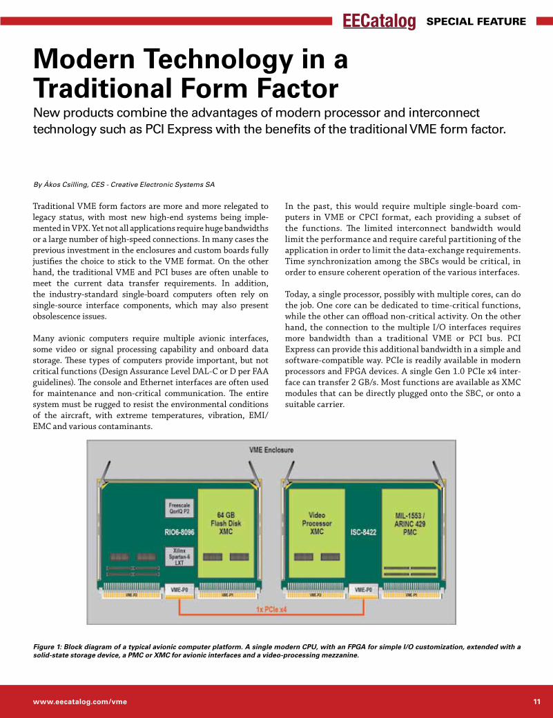
Today, a single processor, possibly with multiple cores, can do the job. One core can be dedicated to time-critical functions, while the other can offload non-critical activity. On the other hand, the connection to the multiple I/O interfaces requires more bandwidth than a traditional VME or PCI bus. PCI Express can provide this additional bandwidth in a simple and software-compatible way. PCIe is readily available in modern processors and FPGA devices. A single Gen 1.0 PCIe x4 inter-face can transfer 2 GB/s. Most functions are available as XMC modules that can be directly plugged onto the SBC, or onto a suitable carrier.
By Ákos Csilling, CES - Creative Electronic Systems SA
Modern Technology in a Traditional Form FactorNew products combine the advantages of modern processor and interconnect technology such as PCI Express with the benefits of the traditional VME form factor.
Figure 1: Block diagram of a typical avionic computer platform. A single modern CPU, with an FPGA for simple I/O customization, extended with a solid-state storage device, a PMC or XMC for avionic interfaces and a video-processing mezzanine.
12 Engineers’ Guide to VME, VPX & VXS 2014
Special Feature
to provide discrete and serial I/O. The electrical interfaces for these signals were installed on an overlay backplane, which also provided the PCIe link through the VME-P0 to a switching carrier installed in a second VME slot. An avionic I/O module and a video compression engine were installed on this carrier, completing the functionality.
A sealed, conduction-cooled enclosure was already available, with an integrated VME64x backplane and power supply. The external connectors and the electrical protection devices were installed on a separate protection board, linked to the overlay backplane through a flexible PCB connection, with an addi-tional board for the electrical filter and the hold-up capacitors.
The resulting design provides new technology with the Fre-escale QorIQ processor and the PCIe interconnect in the proven mechanical and electrical environment of a VME64x system.
Ákos Csilling is a product development manager at CES - Creative Electronic Systems SA. He works with the CTO on the product strategy and roadmap. Previously he managed the develop-ment of VME-based and custom avionic computer platforms. Before he joined CES in 2003, he was a post-doctoral fellow at CERN, the European Organization for Nuclear Research. He holds an MSc and a PhD in Physics from Eotvos University in Budapest and is pursuing an executive MBA at HEC Geneva.
The VITA 41 (VXS) format replaces the VME-P0 connector with a more powerful one that allows the transmission of eight pairs of high-speed signals, up to 10Gb/s; for example PCIe, SRIO or any other serial protocol. The standard allows the signals to be routed in multiple topologies, for example in a daisy chain to adjacent slots, or in a star or dual-star to one or two central switch slots, for larger systems. While VXS does definitely increase the bandwidth available, and does allow the coexistence of new and old boards, it also requires a new backplane. Still, VXS is successful in a number of applications where it allows a gradual transition from VME or CPCI to a switched serial fabric.
The PCIe over P0 technology introduced recently by some vendors extends this possibility to the traditional VME form factor. This new technology allows the continued use of the existing VME64x systems, including the backplanes and legacy boards, to achieve up to 2 GB/s point-to-point transfer rates. The technology is based on a special P0 connector on the board in order to provide extended signal integrity to allow the establishment of PCIe links between two or three VME slots over the traditional VME-P0 connector of the backplane. These signals are not routed in the backplane, but in a custom overlay, allowing any interconnect topology. This technology provides a cost-effective solution to increase data transfer rates between a small number of processors in any VME64x systems, without the need to replace the existing backplane.
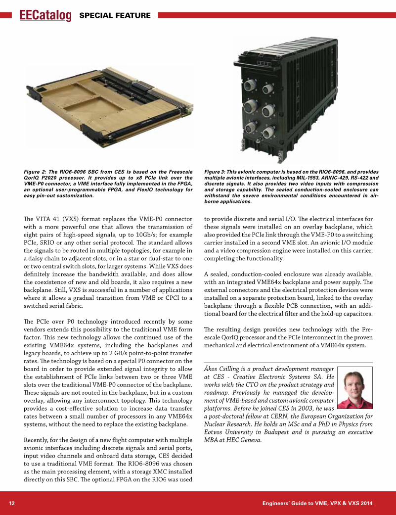
Recently, for the design of a new flight computer with multiple avionic interfaces including discrete signals and serial ports, input video channels and onboard data storage, CES decided to use a traditional VME format. The RIO6-8096 was chosen as the main processing element, with a storage XMC installed directly on this SBC. The optional FPGA on the RIO6 was used
Figure 3: This avionic computer is based on the RIO6-8096, and provides multiple avionic interfaces, including MIL-1553, ARINC-429, RS-422 and discrete signals. It also provides two video inputs with compression and storage capability. The sealed conduction-cooled enclosure can withstand the severe environmental conditions encountered in air-borne applications.
Figure 2: The RIO6-8096 SBC from CES is based on the Freescale QorIQ P2020 processor. It provides up to x8 PCIe link over the VME-P0 connector, a VME interface fully implemented in the FPGA, an optional user-programmable FPGA, and FlexIO technology for easy pin-out customization.
www.eecatalog.com/vme 13
Special Feature
Small form factor military needs are increasing as the battle-field evolves from big, manned crafts to small, unmanned crafts. Why is this trend happening? The different theaters throughout the world require more and more “safe” recon-naissance and intelligence as activities are shifting from face-to face combat to highly computerized and integrated electronics platforms where humans are further away from direct enemy contact.
Where only years ago an intelligence unit would be sent out on foot to scope out the enemy, today’s field units utilize drones, IP radio networks, small unmanned crafts and elec-tronic equipment. Whether they have cameras, software defined radio units, weapon systems or any other elec-tronics in their cargo bays and pods, the emphasis is always on small. With its stated goal of defining standards and specifications for mission-critical systems like defense, avi-onics and UAVs, VITA’s smallest standard is the successful 3U size (100 mm). But add several modules, a backplane and a chassis and the system might be too big for unmanned UAV crafts. That’s where VITA 73 comes in as a smaller alternative to 3U systems.
The Smallest Was 3U VPXVITA’s 3U VPX (officially called VITA 46) is the organiza-tion’s latest ratified standard and was used in Afghanistan and Iraq on the bigger, unmanned UAV drones such as Northrop-Grumman’s Global Hawk. As the benefits of this technology where accepted, smaller and smaller crafts have been developed for air, sea and land use. Although general funding has been slacking in the defense industry, new technologies ranging from electronic armor for tanks and fighting vehicles to unmanned crafts and intelligence elec-tronics has increased.
Yet despite the newness and rich features of VPX and its flavors like OpenVPX (VITA 65), over time this standard will again hit the “form factor wall” as did the industry’s pre-vious “darling” 6U CompactPCI when 3U VPX took over the marketplace. SWaP designs need a high ratio of the available board area for components compared with the total outside dimensions of the given chassis. By radically eliminating everything that is not really needed—like wedgelocks or bulky VPX MultiGig RT connectors—smaller, rugged mod-ules are possible.
Small RequirementsIf a small form factor standard is to be comparable to 3U while using less system real estate in some sort of rugged enclosure, VPX provides an excellent baseline. The require-ments are:
• Capable of sustained operation in any combat or extremeindustrial environment
• Minimizationofsize,weight,andpowerconsumption• Maintainshigh-levels of availability-includinghighMTBF
and low MTTR• Competeswithbiggerstandards like3UVPXbyusingthe
same powerful multicore CPU chips and FPGAs like the Xilinx Virtex-7
• Hasafault-tolerantdesign(diagnosticandprognosticcapa-bilities)
• Hasalong-termmaintenanceandnon-obsolescenceplan• Designedwithfuturetechnologiesinmind• SupportsopticaldatatransferaswellasFPGAusability.
VITA working groups have formed to address this need for a very small rugged form factor. Three key efforts have sur-faced and are actively being worked on, already delivering prototypes and development kits to interested parties as work progresses on the standardization efforts.
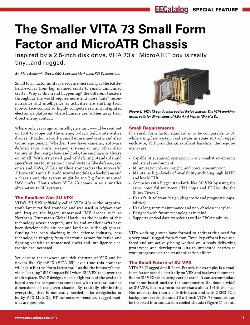
The Small Future of 3U VPXVITA 73 (Rugged Small Form Factor), for example, is a small form factor based electrically on VPX and backwards compat-ible to 3U VPX when using carrier cards. It can accommodate the same board surface for components (in double-wide) as 3U VPX, but in a form factor that’s about 1/4th the size. Not much taller than a soft drink can and with GEN3 PCIe backplane speeds, the small 3 x 4-inch VITA 73 modules can be inserted into conduction cooled chassis (Figure 1) or into
The Smaller VITA 73 Small Form Factor and MicroATR ChassisInspired by a 2.5-inch disk drive, VITA 73’s “MicroATR” box is really tiny...and rugged.
By Marc Benjamin Gross, CEO Sales and Marketing, PCI Systems Inc.
Figure 1: VITA 73 conduction cooled 8-slot chassis. The VITA working group calls for dimensions of 4.5 x 4 x 6 inches (W x H x D).
14 Engineers’ Guide to VME, VPX & VXS 2014
Special Feature
sealed, forced air-cooled microATR rugged military-style computers. They present the integrator with an entirely new approach to SWaP with blazing fast speeds. There are two flavors available: Single modules with a 11.5mm pitch; and double-slot modules with a 23mm pitch where the two PCBs are interconnected with 400 pins from board to board.
Inspired by the 2.5-in SSD form factor, the most important goal during development was to eliminate any bulky parts like connectors, wedgelocks and big guide pins. Instead, the chassis itself is used as a “clam shell”. The biggest ben-efit of VITA 73 is increasing the usable board real estate for components while reducing the cubic footprint ratio. By creating a double slot pack, the available component area is as big as a 3U VPX board but requires only a fraction of chassis real estate.
VITA 73 modules have a full set of I/O pin outs and do away with multiple backplane profiles. Since there currently are only three backplane profiles and a customizable active backplane mezza-nine, designers are able to connect and configure everything as they wish by only changing out the design of the active backplane mezzanine. A designer can place anything from an FPGA to fabric switches to optical module interconnects here to meet any customer demands without confusing them with backplane profiles or slot profiles for each and every different application. [Editor’s note: VITA 65, the interoperable version of VPX called OpenVPX, requires these kinds of profiles to assure interoperability.]
The system connects to the outside world with a full predefined set of electrical and optical I/O pins to keep NRE out of the purchase order. As well, there are several bonus features included in VITA 73. A 10
MHz single-ended frequency is defined to aid in system wide data acquisition and synchronize power supplies. Also, a star trigger and other trigger functions are implemented. For next generations of PCI Express, the usage of the PCIe 100 MHz clock is defined for all boards used in the chassis and a separate instrumentation frequency of 100 MHz is part of the specification.
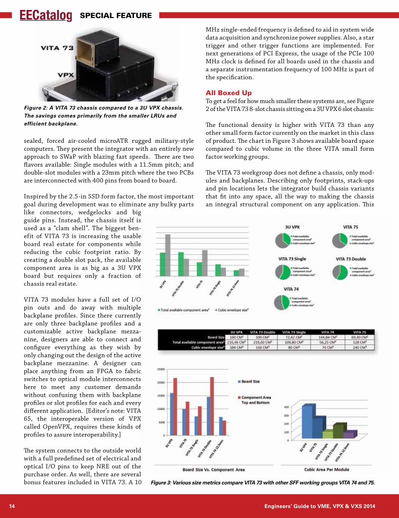
All Boxed UpTo get a feel for how much smaller these systems are, see Figure 2 of the VITA 73 8-slot chassis sitting on a 3U VPX 6 slot chassis:
The functional density is higher with VITA 73 than any other small form factor currently on the market in this class of product. The chart in Figure 3 shows available board space compared to cubic volume in the three VITA small form factor working groups.
The VITA 73 workgroup does not define a chassis, only mod-ules and backplanes. Describing only footprints, stack-ups and pin locations lets the integrator build chassis variants that fit into any space, all the way to making the chassis an integral structural component on any application. This
Figure 2: A VITA 73 chassis compared to a 3U VPX chassis. The savings comes primarily from the smaller LRUs and efficient backplane.
Figure 3: Various size metrics compare VITA 73 with other SFF working groups VITA 74 and 75.
www.eecatalog.com/vme 15
Special Feature
• HighspeedGen3PCIebackplane• 10GBhighspeedmoduletobackplanetransfer• Highdensitydesign• Unlimitedactivebackplanemezzaninecapability• Zerowiresintheentiresystem.
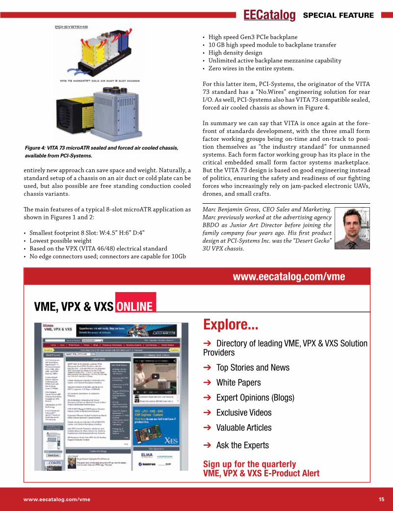
For this latter item, PCI-Systems, the originator of the VITA 73 standard has a “No.Wires” engineering solution for rear I/O. As well, PCI-Systems also has VITA 73 compatible sealed, forced air cooled chassis as shown in Figure 4.
In summary we can say that VITA is once again at the fore-front of standards development, with the three small form factor working groups being on-time and on-track to posi-tion themselves as “the industry standard” for unmanned systems. Each form factor working group has its place in the critical embedded small form factor systems marketplace. But the VITA 73 design is based on good engineering instead of politics, ensuring the safety and readiness of our fighting forces who increasingly rely on jam-packed electronic UAVs, drones, and small crafts.
Marc Benjamin Gross, CEO Sales and Marketing. Marc previously worked at the advertising agency BBDO as Junior Art Director before joining the family company four years ago. His first product design at PCI-Systems Inc. was the “Desert Gecko” 3U VPX chassis.
entirely new approach can save space and weight. Naturally, a standard setup of a chassis on an air duct or cold plate can be used, but also possible are free standing conduction cooled chassis variants.
The main features of a typical 8-slot microATR application as shown in Figures 1 and 2:
• Smallestfootprint8Slot:W:4.5”H:6”D:4”• Lowestpossibleweight• BasedontheVPX(VITA46/48)electricalstandard• Noedgeconnectorsused;connectorsarecapablefor10Gb
Figure 4: VITA 73 microATR sealed and forced air cooled chassis, available from PCI-Systems.
VME, VPX & VXS OnlinE
Explore...➔ Directory of leading VME, VPX & VXS Solution Providers
➔ Top Stories and News
➔ White Papers
➔ Expert Opinions (Blogs)
➔ Exclusive Videos
➔ Valuable Articles
➔ Ask the Experts
Sign up for the quarterly VME, VPX & VXS E-Product Alert
www.eecatalog.com/vme
16 Engineers’ Guide to VME, VPX & VXS 2014
Special Feature
Today’s mil/aero systems are decidedly in the world of multi-core processing. Mainstream processors are available with 10 and 12 cores. Slightly more exotic architectures are available with tens to hundreds of cores (Xeon Phi, Tile, GPGPU). This allows abundant processing power to be applied to problems, but how to keep the cores fed with data? An idle core is a wasted resource. It’s not just bandwidth between resources that is of concern—it’s also the latency incurred in transfers. That can significantly affect the bandwidth for small trans-fers and can also make the system-transfer function exceed its design requirements for real-time operation. Newer archi-tectures allow for techniques such as remote direct memory access (RDMA) and methods that build upon it such as GPU-Direct to be employed to address these issues and to build systems that balance data movement with processing power.
The underlying premise of high-performance embedded com-puting (HPEC) is to leverage the architectures and software that are prevalent in the world of commercial supercomputing and to apply them to the harsh world of mil/aero applica-tions. This has led to a widespread adoption of processors from Intel, AMD and NVIDIA and standard interconnects such as PCI Express, Ethernet and InfiniBand. However, vanilla implementations can fall short of expectations for performance in these demanding applications. For instance, running a TCP/IP stack for a 10GbE link can easily burn up an entire processor core with no cycles left over for computa-tion workloads. Similarly, the measured performance can fall far short of theoretical wire-speed maximums.
Sensor to ProcessorOn the sensor side, it is common to see FPGAs right behind the analog-to-digital converters, with some kind of data link to the processing system. While it is possible to program FPGAs to talk to most of the major protocols, it is most common to see either PCI Express (which is hard-coded into many devices) or a simple interface such as serial FPDP. In systems where the analog acquisition is co-located with the processing, PCI Express is a common choice, but can suffer
from excessive latency and multiple transfers unless some key techniques are employed.
For example, a couple of years ago it was not uncommon to see the data undergo three transfers to get from the sensor to GPU memory ready for processing. This translates into larger latency than may be desired, and to reduced overall band-width due to the data being moved three times. This may be
Multiple Processors in High-Performance Embedded Computing: “Only Connect”Multiprocessing is at the heart of high-performance embedded computing in mil/aero systems—and new technologies enable it to deliver significantly im-proved performance.
By Peter Thompson, GE Intelligent Platforms
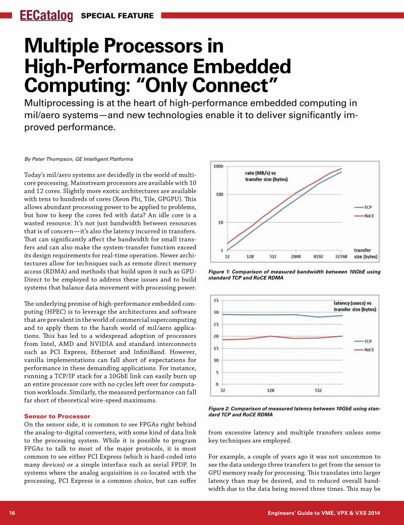
Figure 1: Comparison of measured bandwidth between 10GbE using standard TCP and RoCE RDMA
Figure 2: Comparison of measured latency between 10GbE using stan-dard TCP and RoCE RDMA
www.eecatalog.com/vme 17
Special Feature
tolerable for some applications (such as synthetic aperture radar, where the acquisition of a complete data set takes a long time, and the calculation of an image is not generally needed immediately), but not for others such as tactical radars and electronic warfare systems where a signal must be received, processed and sent out in as little time as possible.
The solution to this problem lies in technology termed GPU-Direct RDMA. The first iteration of GPUDirect removed the host memory-to-host memory transfer by allowing a common address space, eliminating one whole transfer. This reduced latency by around one third. With the introduction of the Kepler family of GPUs and the latest version of CUDA (5.x), NVIDIA removed another transfer step, and now allows the PCI Express endpoint and the GPU to see a piece of each other’s memory, allowing either device to transfer directly to or from the other. This not only removes the need for an extraneous transfer, but also removes the host pro-cessor and operating system from the chain. Measure-ments have shown this to reduce latency by a factor of 15, opening up new applica-tion areas for GPGPU. It is worth noting that none of this requires proprietary mecha-nisms. The interface is standard PCI Express; the transfers use regular DMA mechanisms. It just happens to be that the destination address is an aperture into GPU memory that has been mapped to PCI Express space and is exposed via a simple API call.
Processor to ProcessorWhen it comes to communicating between processors in a multiprocessor system, there are many choices. Intel devices may be connected with QuickPath Interconnect in a symmetrical multi-processing architecture that makes two
processors appear to the operating system as a single large CPU. However, this functionality is generally not available in the devices that are provided in the BGA packages from the extended lifecycle portfolios that are favored for rugged environments—only in socketed versions that are not fully rugged or must go through a complex rework process.
Between boards, most of the major fabric choices are avail-able, but the right choice can have a marked effect on system performance. For example, if standard TCP sockets over 10GbE are used, substantial CPU resources are used up just to manage the transfers—and the data rates achieved are less than optimal. If, however, remote direct memory access (RDMA) is available, the picture changes dramatically. RDMA allows the network interface chips to move data directly from the application space on one board to that on another with no extra copies and no involvement of the host processor once the transfer has been requested. This reduces the amount of CPU cycles used to manage the transfer to single digit per-centages rather than close to one hundred percent. Examples are RDMA over Converged Ethernet (RoCE) from Mellanox and Internet Wide Area RDMA Protocol (iWARP) from Intel. Both have low latency (as low as 1.3 microseconds for RoCE, 3 microseconds for iWARP). Mellanox also supports RDMA over InfiniBand (using the same network interface control-lers (NICs)), allowing the system designer to choose between
the two fabrics. The API to the application remains the same thanks to the OFED (Open Fabrics Enterprise Distribution: open source software for RDMA and kernel bypass applications) stack. (Figure 1, Figure 2).
GPU to GPUSimilar data move-ment issues arise in a heterogeneous HPEC system comprised of one or more host processors and multiple GPUs. In such a system, it is common to view the GPUs as the pri-mary data consumers, with
the host processor(s) being relegated to doing housekeeping functions. Once the data has been deposited into a GPU from a sensor interface (using GPUDirect RDMA), after a first stage of processing it may be necessary to move it to another GPU for the next stage of a pipelined processing scheme.
In the past, this would require the data to be moved from GPU memory to its host system memory, then perhaps to another host processor, then finally down to the memory of the desti-nation GPU. Again, multiple transfers, extra latency, wasted bandwidth and unwanted burden on the hosts. And again, GPUDirect RDMA comes to the rescue via two forms of sup-
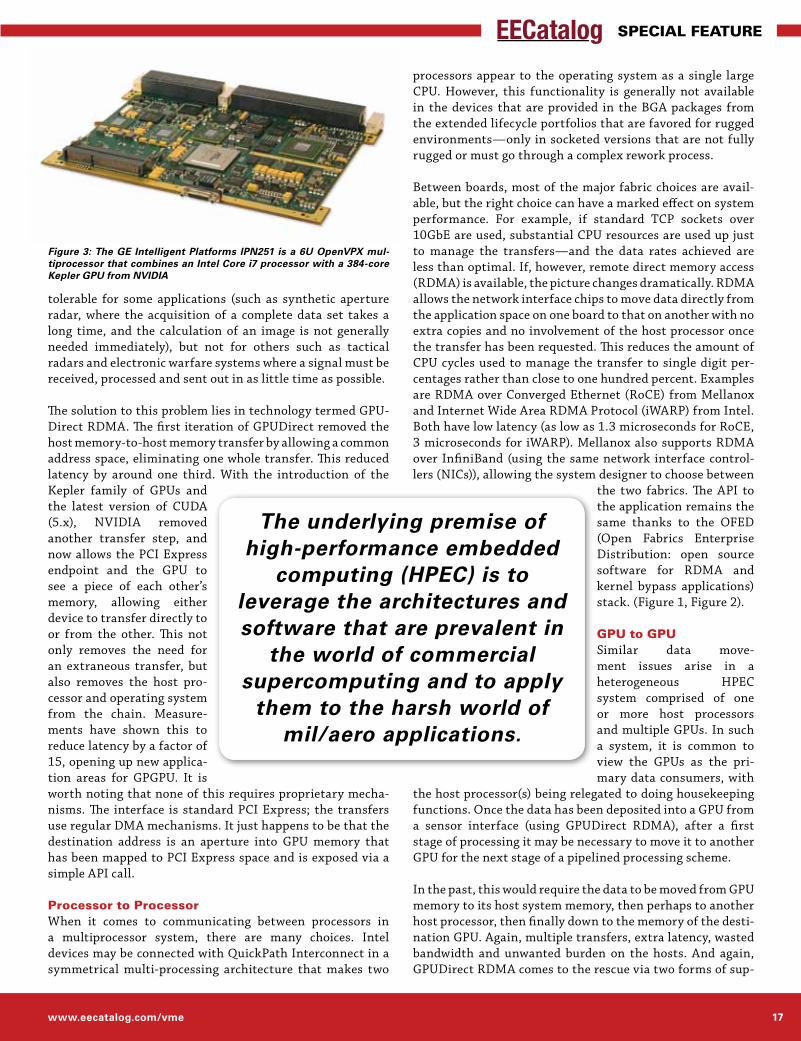
Figure 3: The GE Intelligent Platforms IPN251 is a 6U OpenVPX mul-tiprocessor that combines an Intel Core i7 processor with a 384-core Kepler GPU from NVIDIA
The underlying premise of high-performance embedded
computing (HPEC) is to leverage the architectures and software that are prevalent in
the world of commercial supercomputing and to apply
them to the harsh world of mil/aero applications.
18 Engineers’ Guide to VME, VPX & VXS 2014
Special Feature
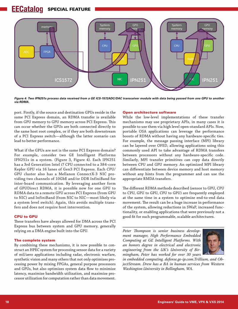
port. Firstly, if the source and destination GPUs reside in the same PCI Express domain, an RDMA transfer is available from GPU memory to GPU memory across PCI Express. This can occur whether the GPUs are both connected directly to the same host root complex, or if they are both downstream of a PCI Express switch—although the latter scenario can lead to better performance.
What if the GPUs are not is the same PCI Express domain? For example, consider two GE Intelligent Platforms IPN251s in a system. (Figure 3, Figure 4). Each IPN251 has a 3rd Generation Intel i7 CPU connected to a 384-core Kepler GPU via 16 lanes of Gen3 PCI Express. Each CPU/GPU cluster also has a Mellanox ConnectX-3 NIC pro-viding two channels of 10GbE and/or DDR InfiniBand for inter-board communication. By leveraging another form of GPUDirect RDMA, it is possible now for one GPU to RDMA data to a remote GPU across PCI Express (from GPU to NIC) and InfiniBand (from NIC to NIC—most likely via a system level switch). Again, this avoids multiple trans-fers and does not require host intervention.
CPU to GPUThese transfers have always allowed for DMA across the PCI Express bus between system and GPU memory, generally relying on a DMA engine built into the GPU.
The complete systemBy combining these mechanisms, it is now possible to con-struct an HPEC system for processing sensor data for a variety of mil/aero applications including radar, electronic warfare, synthetic vision and many others that not only optimizes pro-cessing power by mixing FPGAs, general purpose processors and GPUs, but also optimizes system data flow to minimize latency, maximize bandwidth utilization, and maximize pro-cessor utilization for computation rather than data movement.
Open architecture softwareWhile the low-level implementations of these transfer mechanisms may use proprietary APIs, in many cases it is possible to use them via high level open-standard APIs. Now, portable OSA applications can leverage the performance boosts of RDMA without having any hardware-specific ties. For example, the message passing interface (MPI) library can be layered over OFED, allowing applications using this commonly used API to take advantage of RDMA transfers between processors without any hardware-specific code. Similarly, MPI transfer primitives can copy data directly between CPU and GPU memory. An optimized MPI library can differentiate between device memory and host memory without any hints from the programmer and can use the appropriate RMDA transfers.
The different RDMA methods described (sensor to GPU, CPU to CPU, GPU to GPU, CPU to GPU) are frequently employed at the same time in a system to optimize end-to-end data movement. The result can be a huge increase in performance of the system, allowing reductions in SWaP, increased func-tionality, or enabling applications that were previously not a good fit for such programmable, scalable architectures.
Peter Thompson is senior business develop-ment manager, High Performance Embedded Computing at GE Intelligent Platforms. With an honors degree in electrical and electronic engineering from the UK’s University of Bir-mingham, Peter has worked for over 30 years in embedded computing. defense.ge-ip.com.Trillium, and Ob-jectStream. Drew has a BA in human services from Western Washington University in Bellingham, WA.
Figure 4: Two IPN251s process data received from a GE ICS-1572ADC/DAC transceiver module with data being passed from one GPU to another via RDMA.
www.eecatalog.com/vme 19
Special Feature
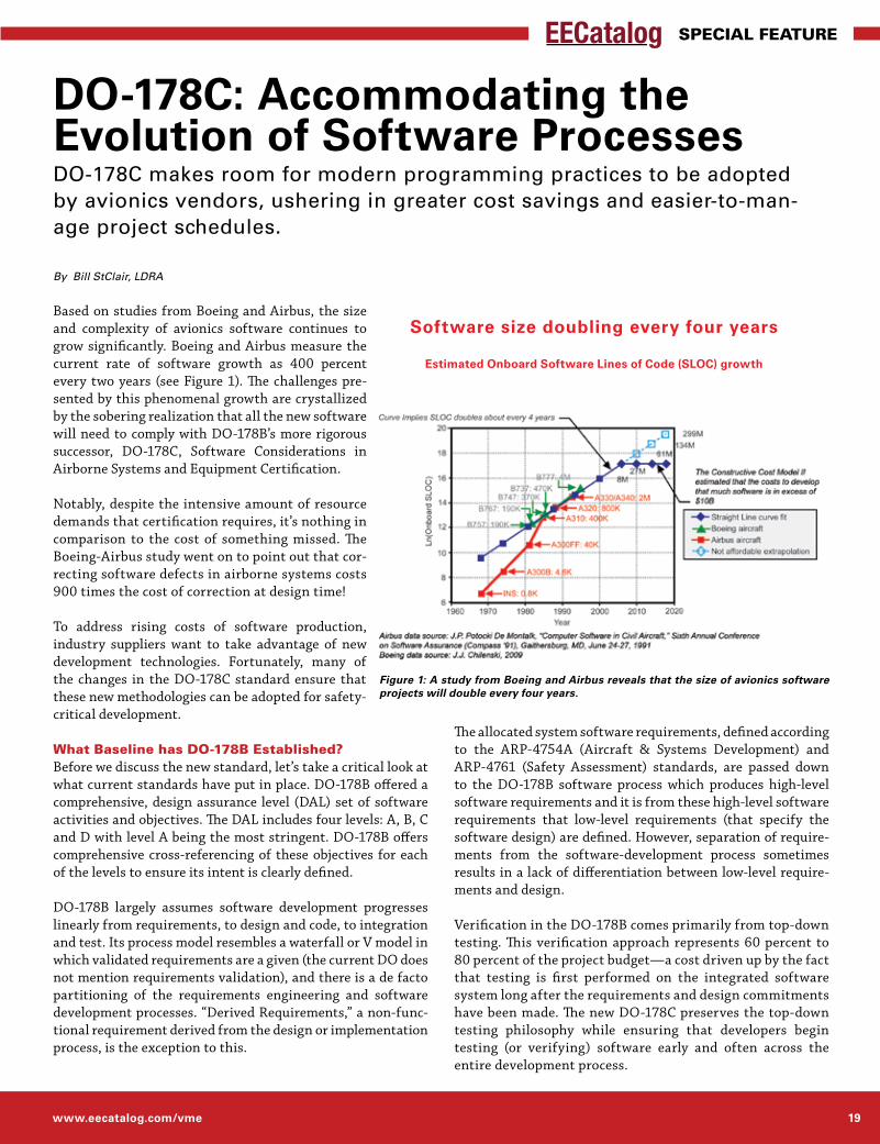
Based on studies from Boeing and Airbus, the size and complexity of avionics software continues to grow significantly. Boeing and Airbus measure the current rate of software growth as 400 percent every two years (see Figure 1). The challenges pre-sented by this phenomenal growth are crystallized by the sobering realization that all the new software will need to comply with DO-178B’s more rigorous successor, DO-178C, Software Considerations in Airborne Systems and Equipment Certification.
Notably, despite the intensive amount of resource demands that certification requires, it’s nothing in comparison to the cost of something missed. The Boeing-Airbus study went on to point out that cor-recting software defects in airborne systems costs 900 times the cost of correction at design time!
To address rising costs of software production, industry suppliers want to take advantage of new development technologies. Fortunately, many of the changes in the DO-178C standard ensure that these new methodologies can be adopted for safety-critical development.
What Baseline has DO-178B Established?Before we discuss the new standard, let’s take a critical look at what current standards have put in place. DO-178B offered a comprehensive, design assurance level (DAL) set of software activities and objectives. The DAL includes four levels: A, B, C and D with level A being the most stringent. DO-178B offers comprehensive cross-referencing of these objectives for each of the levels to ensure its intent is clearly defined.
DO-178B largely assumes software development progresses linearly from requirements, to design and code, to integration and test. Its process model resembles a waterfall or V model in which validated requirements are a given (the current DO does not mention requirements validation), and there is a de facto partitioning of the requirements engineering and software development processes. “Derived Requirements,” a non-func-tional requirement derived from the design or implementation process, is the exception to this.
The allocated system software requirements, defined according to the ARP-4754A (Aircraft & Systems Development) and ARP-4761 (Safety Assessment) standards, are passed down to the DO-178B software process which produces high-level software requirements and it is from these high-level software requirements that low-level requirements (that specify the software design) are defined. However, separation of require-ments from the software-development process sometimes results in a lack of differentiation between low-level require-ments and design.
Verification in the DO-178B comes primarily from top-down testing. This verification approach represents 60 percent to 80 percent of the project budget—a cost driven up by the fact that testing is first performed on the integrated software system long after the requirements and design commitments have been made. The new DO-178C preserves the top-down testing philosophy while ensuring that developers begin testing (or verifying) software early and often across the entire development process.
DO-178C: Accommodating the Evolution of Software ProcessesDO-178C makes room for modern programming practices to be adopted by avionics vendors, ushering in greater cost savings and easier-to-man-age project schedules.
By Bill StClair, LDRA
Figure 1: A study from Boeing and Airbus reveals that the size of avionics software projects will double every four years.
Software size doubling every four years
Estimated Onboard Software Lines of Code (SLOC) growth
20 Engineers’ Guide to VME, VPX & VXS 2014
Special Feature
DO verification focuses on test coverage of functional require-ments and software structures. These structures include code structures, measured as statement and decision coverage as well as data and program-control structures. The measure-ment of data and control coupling is typically performed as a manual, ad hoc analytical pro-cess, contributing to increased verification costs.
Finally, in the DO-178B, traceability (i.e., causal links between requirements at dif-ferent levels and associated software development arti-facts) have been established before the software system is considered certifiable. These causal links include both static links that must be established and maintained (e.g., mapping from low-level requirements to source code) and dynamically measured links (e.g., as utilized by structural coverage analysis).
Typical certification readiness activities include a verifi-cation of traceability called slice analysis, which follows one high-level software requirement to its low-level requirement(s) and associated test cases through design to source code and then to object code.
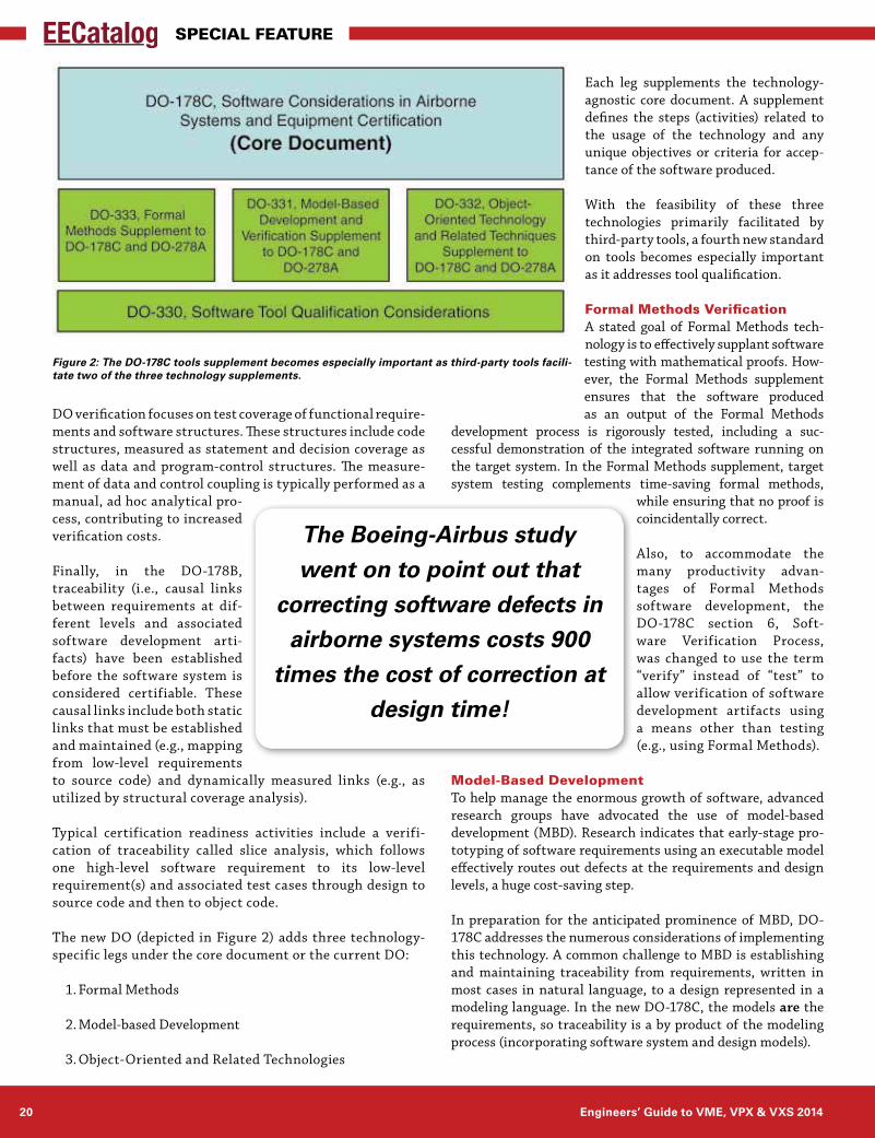
The new DO (depicted in Figure 2) adds three technology-specific legs under the core document or the current DO:
1. Formal Methods
2. Model-based Development
3. Object-Oriented and Related Technologies
Each leg supplements the technology-agnostic core document. A supplement defines the steps (activities) related to the usage of the technology and any unique objectives or criteria for accep-tance of the software produced.
With the feasibility of these three technologies primarily facilitated by third-party tools, a fourth new standard on tools becomes especially important as it addresses tool qualification.
Formal Methods VerificationA stated goal of Formal Methods tech-nology is to effectively supplant software testing with mathematical proofs. How-ever, the Formal Methods supplement ensures that the software produced as an output of the Formal Methods
development process is rigorously tested, including a suc-cessful demonstration of the integrated software running on the target system. In the Formal Methods supplement, target system testing complements time-saving formal methods,
while ensuring that no proof is coincidentally correct.
Also, to accommodate the many productivity advan-tages of Formal Methods software development, the DO-178C section 6, Soft-ware Verification Process, was changed to use the term “verify” instead of “test” to allow verification of software development artifacts using a means other than testing (e.g., using Formal Methods).
Model-Based DevelopmentTo help manage the enormous growth of software, advanced research groups have advocated the use of model-based development (MBD). Research indicates that early-stage pro-totyping of software requirements using an executable model effectively routes out defects at the requirements and design levels, a huge cost-saving step.
In preparation for the anticipated prominence of MBD, DO-178C addresses the numerous considerations of implementing this technology. A common challenge to MBD is establishing and maintaining traceability from requirements, written in most cases in natural language, to a design represented in a modeling language. In the new DO-178C, the models are the requirements, so traceability is a by product of the modeling process (incorporating software system and design models).
Figure 2: The DO-178C tools supplement becomes especially important as third-party tools facili-tate two of the three technology supplements.
The Boeing-Airbus study went on to point out that
correcting software defects in airborne systems costs 900
times the cost of correction at design time!
www.eecatalog.com/vme 21
Special Feature
However, other questions about traceability arise when the MBD process auto-generates source code: How do you map requirements to source code? How do you refine these mappings and the software behavior that they encapsulate? The answer to these questions depends on the characteristics of the modeling language and the mechanisms supported by the MBD tool auto-generating the code. MBD tools may also insert code that can be rationalized only in the context of the model ’s implemen-tation, not the functional requirements.
Because the DO-178 standard requires direct mapping between requirements and source code, unmapped code must be accounted for. In these circumstances, what should the applicant do—define “derived” requirements to justify the unmapped code?
As a direct consequence of MBD limitations on implementing software behavior—including such things as hardware driver code or timing critical, multi threaded operations—MBD systems typically require some hand-coding along with the auto-generated code. In addition to the different verifi-cation techniques that must be employed with hybrid systems, two distinct traceability tech-niques must be unified.
OO Technology and Related TechniquesThe third technology supplement for the new DO, Object Ori-ented Technology and Related Techniques (OOT) focuses on OO languages in use today such as C++, Java and Ada 2005 along with guidance for technologies common to both OO languages and procedural languages (e.g., polymorphism with multiple inheritance and generics and function dispatch with dynamic and static dispatch).
Subtyping, the OOT ability to create new types or subtypes increases the power of object-oriented languages, but it introduces the challenge of maintaining type consistency and verification of subtypes. Reacting to the potentially enormous number of feasibly executable methods, the FAA’s Object Ori-ented Technology in Aviation (OOTIA) Handbook defaulted to an exhaustive, flattened-class approach, which significantly escalates OOT verification costs in DO-178B.
The OOT Supplement for DO-178C recommends a far more practical approach to establish type substitutability. Design Verification Testing (DVT), performed at the class level, proves that all the member functions conform to the class contract with respect to preconditions, post conditions, and invariants of the class state. As an alternative to DVT, developers can use formal methods in conformance with the Formal Methods Supplement.
ConclusionDoes DO-178C provide the guidance necessary to facilitate the acceptance of advanced technologies covered by its supplements? Yes, absolutely. Developers now have many labor-saving technologies that they can use to help reign in project and schedule bloat. And tool developers continue to improve integrations to ease this development. For example, LDRA and Mathworks announced (http://www.ldra.com/en/component/content/article/11-news-press-releases/678-ldra-extends-integration-with-matlab-and-simulink-verifying-the-model-at-object-code-level-) an integration that enabled designers to verify the model to DO-178C Level A.
But the real issue—the elephant in the room—lies in whether the use of these new development technologies will help applicants manage the avalanche of avionics software in the coming years?
That answer depends on the adoption of more agile and f lexible development and verification processes that incorporate such objectives as continuous requirements, verification and lifecycle trace-ability.
I look forward to seeing the new generation of software verification tools automate and
replace manual and inefficient techniques. These steps will go a long way towards bringing about consistent, cost-effective development processes as software continues to grow in com-plexity and scope.
Bill StClair is currently director, US Operations for LDRA Technology and LDRA Certification Services and has more than 25 years in embed-ded software development and management. He has worked in the avionics, defense, space, com-munications, industrial controls and commercial industries as a developer, verification engineer, manager and com-pany founder. He holds a U.S. patent for a portable storage system and is inventor of a patent-pending embedded requirements veri-fication system. Bill’s leadership was instrumental in adapting requirements traceability into LDRA’s verification process.
In DO-178C, to ensure that the software is rigorously tested there must be a successful
demonstration of the software running on the target system.
22 Engineers’ Guide to VME, VPX & VXS 2014
Special Feature
The VITA community continues to develop new and exciting embedded computing products. But it is not very often that we see the tangential tools that provide more versatility for your designs. This includes specialty carriers for PMCs, XMCs, COM Express and more. These tools expand a designer’s options, often preventing the need for expen-sive customization while reducing design risk.
Advantages of MezzaninesCOM Express and PMCs/XMCs/FMCs are advantageous because there is a wide range of standard modules available in the marketplace. The I/O options are readily available in many configurations. Allowing for these mezzanine modules in a standard VITA-based form factor provides ver-satility for legacy systems.
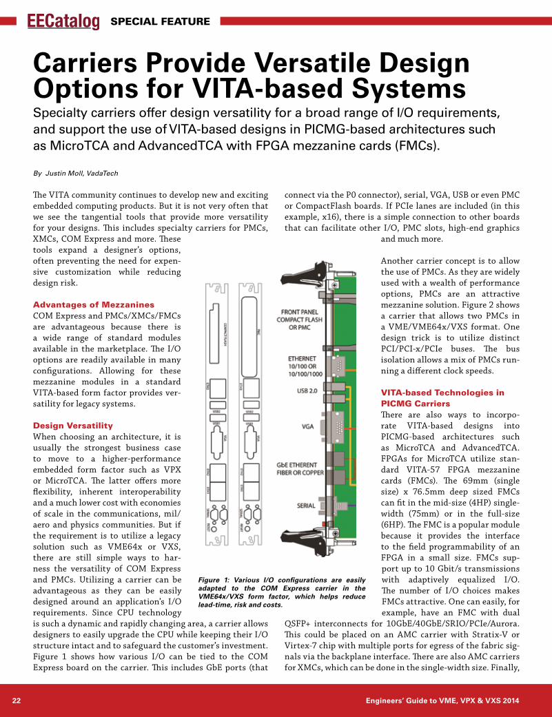
Design VersatilityWhen choosing an architecture, it is usually the strongest business case to move to a higher-performance embedded form factor such as VPX or MicroTCA. The latter offers more flexibility, inherent interoperability and a much lower cost with economies of scale in the communications, mil/aero and physics communities. But if the requirement is to utilize a legacy solution such as VME64x or VXS, there are still simple ways to har-ness the versatility of COM Express and PMCs. Utilizing a carrier can be advantageous as they can be easily designed around an application’s I/O requirements. Since CPU technology is such a dynamic and rapidly changing area, a carrier allows designers to easily upgrade the CPU while keeping their I/O structure intact and to safeguard the customer’s investment. Figure 1 shows how various I/O can be tied to the COM Express board on the carrier. This includes GbE ports (that
connect via the P0 connector), serial, VGA, USB or even PMC or CompactFlash boards. If PCIe lanes are included (in this example, x16), there is a simple connection to other boards that can facilitate other I/O, PMC slots, high-end graphics
and much more.
Another carrier concept is to allow the use of PMCs. As they are widely used with a wealth of performance options, PMCs are an attractive mezzanine solution. Figure 2 shows a carrier that allows two PMCs in a VME/VME64x/VXS format. One design trick is to utilize distinct PCI/PCI-x/PCIe buses. The bus isolation allows a mix of PMCs run-ning a different clock speeds.
VITA-based Technologies in PICMG CarriersThere are also ways to incorpo-rate VITA-based designs into PICMG-based architectures such as MicroTCA and AdvancedTCA. FPGAs for MicroTCA utilize stan-dard VITA-57 FPGA mezzanine cards (FMCs). The 69mm (single size) x 76.5mm deep sized FMCs can fit in the mid-size (4HP) single-width (75mm) or in the full-size (6HP). The FMC is a popular module because it provides the interface to the field programmability of an FPGA in a small size. FMCs sup-port up to 10 Gbit/s transmissions with adaptively equalized I/O. The number of I/O choices makes FMCs attractive. One can easily, for example, have an FMC with dual
QSFP+ interconnects for 10GbE/40GbE/SRIO/PCIe/Aurora. This could be placed on an AMC carrier with Stratix-V or Virtex-7 chip with multiple ports for egress of the fabric sig-nals via the backplane interface. There are also AMC carriers for XMCs, which can be done in the single-width size. Finally,
Carriers Provide Versatile Design Options for VITA-based SystemsSpecialty carriers offer design versatility for a broad range of I/O requirements, and support the use of VITA-based designs in PICMG-based architectures such as MicroTCA and AdvancedTCA with FPGA mezzanine cards (FMCs).
By Justin Moll, VadaTech
Figure 1: Various I/O configurations are easily adapted to the COM Express carrier in the VME64x/VXS form factor, which helps reduce lead-time, risk and costs.
www.eecatalog.com/vme 23
Special Feature
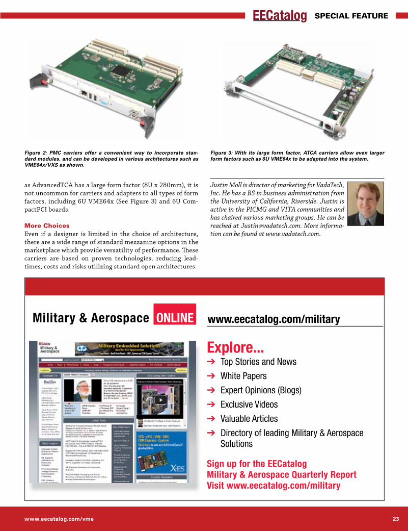
Figure 2: PMC carriers offer a convenient way to incorporate stan-dard modules, and can be developed in various architectures such as VME64x/VXS as shown.
Figure 3: With its large form factor, ATCA carriers allow even larger form factors such as 6U VME64x to be adapted into the system.
as AdvancedTCA has a large form factor (8U x 280mm), it is not uncommon for carriers and adapters to all types of form factors, including 6U VME64x (See Figure 3) and 6U Com-pactPCI boards.
More ChoicesEven if a designer is limited in the choice of architecture, there are a wide range of standard mezzanine options in the marketplace which provide versatility of performance. These carriers are based on proven technologies, reducing lead-times, costs and risks utilizing standard open architectures.
Justin Moll is director of marketing for VadaTech, Inc. He has a BS in business administration from the University of California, Riverside. Justin is active in the PICMG and VITA communities and has chaired various marketing groups. He can be reached at [email protected]. More informa-tion can be found at www.vadatech.com.
www.eecatalog.com/militaryMilitary & Aerospace Online
explore...➔ Top Stories and News
➔ White Papers
➔ Expert Opinions (Blogs)
➔ Exclusive Videos
➔ Valuable Articles
➔ Directory of leading Military & Aerospace Solutions Sign up for the eeCatalog Military & Aerospace Quarterly ReportVisit www.eecatalog.com/military
24 • Hardware Engineers’ Guide to VME, VPX & VXS 2014
ContaCt InformatIon
sie-cs.com
SIE Computing Solutions | 10 Mupac Drive | Brockton, MA 02301 | 508-588-6110
Enclosures
Backplanes
System Integration & Custom Solutions
cPCI
VME
Open VPX
xTCA
rugged & ready when you are
SIE_Half_Page Extension_Media_final.indd 1 1/10/13 1:19 PM
ContaCt InformatIon
SIE Computing Solutions
sIe Computing solutions10 Mupac DriveBrockton, MA 02301UsA800.926.8722 toll Free508.588.6110 telephone508.588.0498 Faxwww.sie-cs.com
AVAIlABIlITy
Now
APPlICATIOn AREAS
Military/Aerospace, Industrial, Transportation
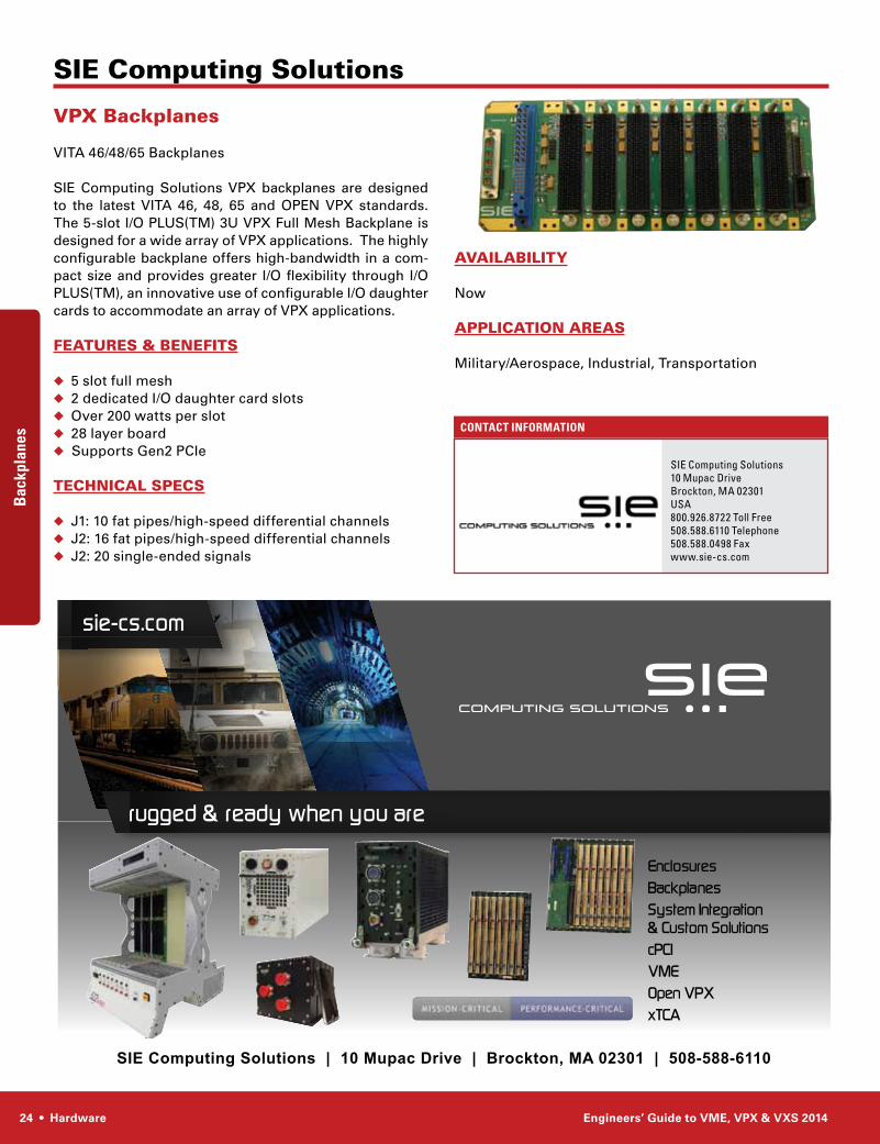
VPX Backplanes
VITA 46/48/65 Backplanes
SIE Computing Solutions VPX backplanes are designed to the latest VITA 46, 48, 65 and OPEN VPX standards. The 5-slot I/O PLUS(TM) 3U VPX Full Mesh Backplane is designed for a wide array of VPX applications. The highly configurable backplane offers high-bandwidth in a com-pact size and provides greater I/O flexibility through I/O PLUS(TM), an innovative use of configurable I/O daughter cards to accommodate an array of VPX applications.
FEATURES & BEnEFITS
◆ 5 slot full mesh◆ 2 dedicated I/O daughter card slots◆ Over 200 watts per slot◆ 28 layer board◆ Supports Gen2 PCIe
TEChnICAl SPECS
◆ J1: 10 fat pipes/high-speed differential channels◆ J2: 16 fat pipes/high-speed differential channels◆ J2: 20 single-ended signals
BackplanesB
ackp
lane
s
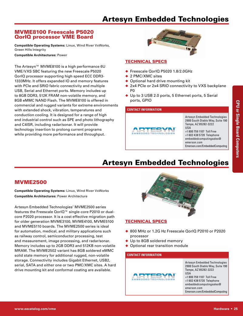
www.eecatalog.com/vme Hardware • 25
ContaCt InformatIon
Artesyn Embedded Technologies
TEChnICAl SPECS
◆ Freescale QorIQ P5020 1.8/2.0GHz ◆ 2 PMC/XMC sites◆ Optional hard drive mounting kit ◆ 2x4 PCIe or 2x4 SRIO connectivity to VXS backplane
P0◆ Up to 3 USB 2.0 ports, 5 Ethernet ports, 5 Serial
ports, GPIO
MVME8100 Freescale P5020 QorIQ processor VME Board Compatible Operating Systems: Linux, Wind River VxWorks, Green Hills Integrity
Compatible Architectures: Power
The Artesyn™ MVME8100 is a high performance 6U VME/VXS SBC featuring the new Freescale P5020 QorIQ processor supporting high speed ECC DDR3-1333MHz. It offers expanded IO and memory features with PCIe and SRIO fabric connectivity and multiple USB, Serial and Ethernet ports. Memory includes up to 8GB DDR3, 512K FRAM non-volatile memory, and 8GB eMMC NAND Flash. The MVME8100 is offered in commercial and rugged variants for extreme environments with extended shock, vibration, temperatures and conduction cooling. It is designed for a range of high end industrial control such as SPE and photo lithography and C4ISR, including radar/sonar. It will provide technology insertion to prolong current programs while providing more performance and throughput.
CPU or Single B
oard ComputersCP
U o
r Sin
gle
Boa
rd C
ompu
ters
ContaCt InformatIon
Artesyn embedded technologies2900 south Diablo Way, suite 190 tempe, AZ 85282-3222UsA+1 800 759 1107 toll Free+1 602 438 5720 telephone [email protected] emerson.com/embeddedComputing
TEChnICAl SPECS
◆ 800 MHz or 1.2G Hz Freescale QorIQ P2010 or P2020 processor
◆ Up to 8GB soldered memory ◆ Optional rear transition module
MVME2500 Compatible Operating Systems: Linux, Wind River VxWorks
Compatible Architectures: Power Architecture
Artesyn Embedded Technologies’ MVME2500 series features the Freescale QorIQ™ single-core P2010 or dual-core P2020 processor. It is a cost effective migration path for older generation MVME3100, MVME4100, MVME5100 and MVME5110 boards. The MVME2500 series is ideal for automation, medical, and military applications such as railway control, semiconductor processing, test and measurement, image processing, and radar/sonar. Memory includes up to 2GB DDR3 and 512KB non-volatile MRAM. The MVME2502 variant has 8GB soldered eMMC solid state memory for additional rugged, non-volatile storage. Connectivity includes Gigabit Ethernet, USB2, serial, SATA and either one or two PMC/XMC sites. A hard drive mounting kit and conformal coating are available.
Artesyn Embedded Technologies
Artesyn embedded technologies2900 south Diablo Way, suite 190 tempe, AZ 85282-3222UsA+1 800 759 1107 toll Free+1 602 438 5720 telephone [email protected] emerson.com/embeddedComputing
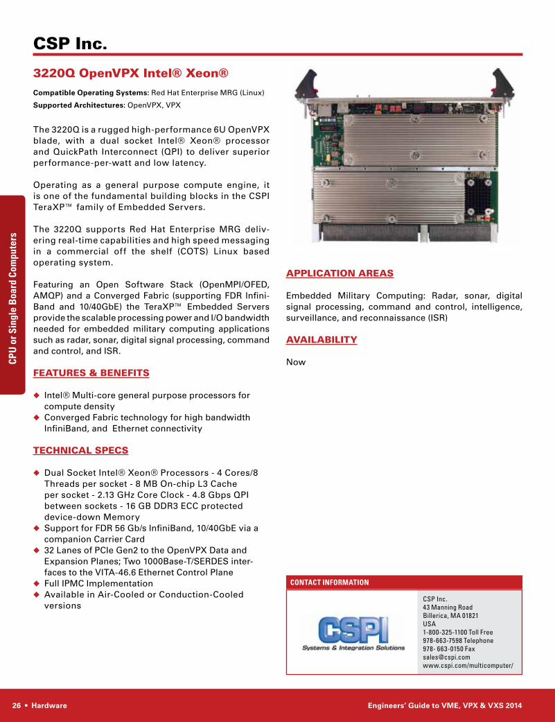
26 • Hardware Engineers’ Guide to VME, VPX & VXS 2014
ContaCt InformatIon
CSP Inc.
CsP Inc.43 Manning RoadBillerica, MA 01821UsA1-800-325-1100 toll Free978-663-7598 telephone978- 663-0150 [email protected]/multicomputer/
APPlICATIOn AREAS
Embedded Military Computing: Radar, sonar, digital signal processing, command and control, intelligence, surveillance, and reconnaissance (ISR)
AVAIlABIlITy
Now
3220Q OpenVPX Intel® Xeon® Compatible Operating Systems: Red Hat Enterprise MRG (Linux)
Supported Architectures: OpenVPX, VPX
The 3220Q is a rugged high-performance 6U OpenVPX blade, with a dual socket Intel® Xeon® processor and QuickPath Interconnect (QPI) to deliver superior performance-per-watt and low latency.
Operating as a general purpose compute engine, it is one of the fundamental building blocks in the CSPI TeraXP™ family of Embedded Servers.
The 3220Q supports Red Hat Enterprise MRG deliv-ering real-time capabilities and high speed messaging in a commercial off the shelf (COTS) Linux based operating system.
Featuring an Open Software Stack (OpenMPI/OFED, AMQP) and a Converged Fabric (supporting FDR Infini-Band and 10/40GbE) the TeraXP™ Embedded Servers provide the scalable processing power and I/O bandwidth needed for embedded military computing applications such as radar, sonar, digital signal processing, command and control, and ISR.
FEATURES & BEnEFITS
◆ Intel® Multi-core general purpose processors for compute density
◆ Converged Fabric technology for high bandwidth InfiniBand, and Ethernet connectivity
TEChnICAl SPECS
◆ Dual Socket Intel® Xeon® Processors - 4 Cores/8 Threads per socket - 8 MB On-chip L3 Cache per socket - 2.13 GHz Core Clock - 4.8 Gbps QPI between sockets - 16 GB DDR3 ECC protected device-down Memory
◆ Support for FDR 56 Gb/s InfiniBand, 10/40GbE via a companion Carrier Card
◆ 32 Lanes of PCIe Gen2 to the OpenVPX Data and Expansion Planes; Two 1000Base-T/SERDES inter-faces to the VITA-46.6 Ethernet Control Plane
◆ Full IPMC Implementation◆ Available in Air-Cooled or Conduction-Cooled
versions
CPU or Single B
oard ComputersCP
U o
r Sin
gle
Boa
rd C
ompu
ters
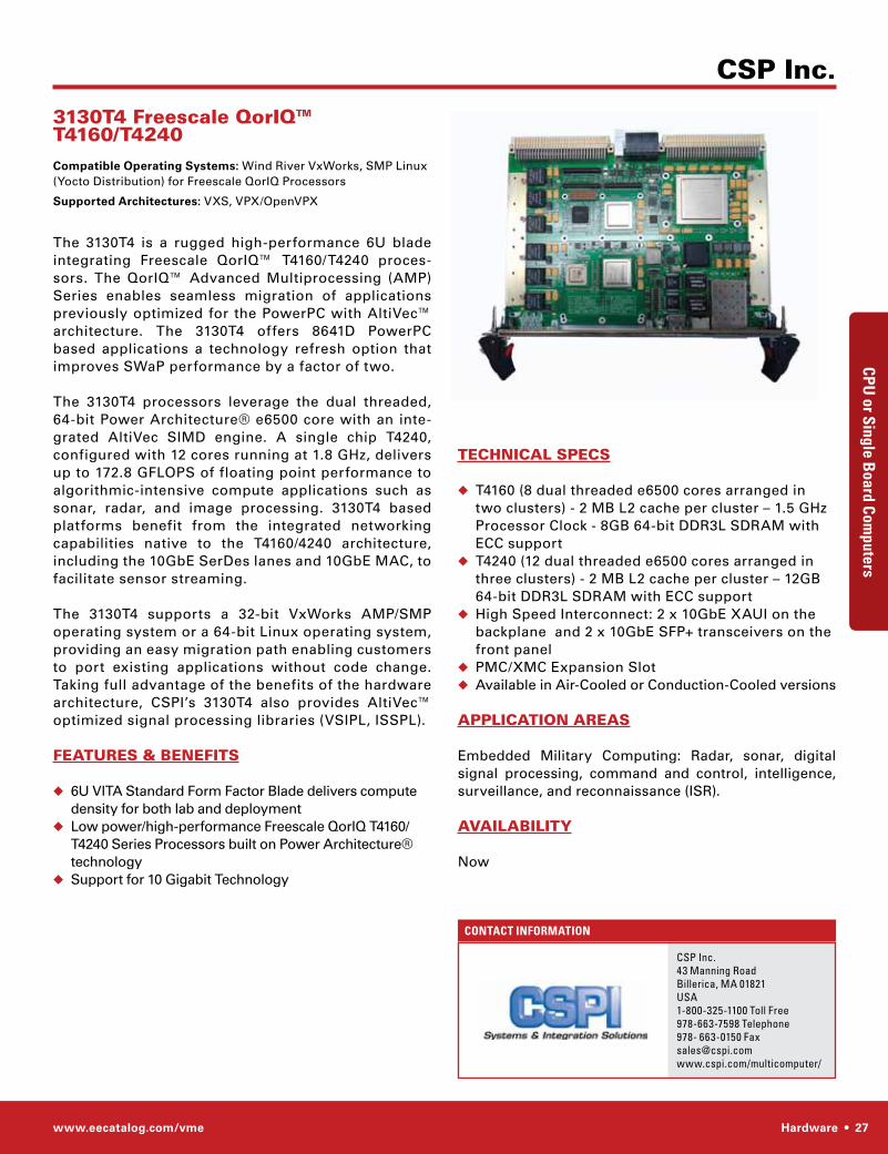
www.eecatalog.com/vme Hardware • 27
ContaCt InformatIon
CSP Inc.
CsP Inc.43 Manning RoadBillerica, MA 01821UsA1-800-325-1100 toll Free978-663-7598 telephone978- 663-0150 [email protected]/multicomputer/
TEChnICAl SPECS
◆ T4160 (8 dual threaded e6500 cores arranged in two clusters) - 2 MB L2 cache per cluster – 1.5 GHz Processor Clock - 8GB 64-bit DDR3L SDRAM with ECC support
◆ T4240 (12 dual threaded e6500 cores arranged in three clusters) - 2 MB L2 cache per cluster – 12GB 64-bit DDR3L SDRAM with ECC support
◆ High Speed Interconnect: 2 x 10GbE XAUI on the backplane and 2 x 10GbE SFP+ transceivers on the front panel
◆ PMC/XMC Expansion Slot ◆ Available in Air-Cooled or Conduction-Cooled versions
APPlICATIOn AREAS
Embedded Military Computing: Radar, sonar, digital signal processing, command and control, intelligence, surveillance, and reconnaissance (ISR).
AVAIlABIlITy
Now
3130T4 Freescale QorIQ™ T4160/T4240 Compatible Operating Systems: Wind River VxWorks, SMP Linux (Yocto Distribution) for Freescale QorIQ Processors
Supported Architectures: VXS, VPX/OpenVPX
The 3130T4 is a rugged high-performance 6U blade integrating Freescale QorIQ™ T4160/T4240 proces-sors. The QorIQ™ Advanced Multiprocessing (AMP) Series enables seamless migration of applications previously optimized for the PowerPC with AltiVec™ architecture. The 3130T4 offers 8641D PowerPC based applications a technology refresh option that improves SWaP performance by a factor of two.
The 3130T4 processors leverage the dual threaded, 64-bit Power Architecture® e6500 core with an inte-grated AltiVec SIMD engine. A single chip T4240, configured with 12 cores running at 1.8 GHz, delivers up to 172.8 GFLOPS of floating point performance to algorithmic-intensive compute applications such as sonar, radar, and image processing. 3130T4 based platforms benefit from the integrated networking capabilities native to the T4160/4240 architecture, including the 10GbE SerDes lanes and 10GbE MAC, to facilitate sensor streaming.
The 3130T4 supports a 32-bit VxWorks AMP/SMP operating system or a 64-bit Linux operating system, providing an easy migration path enabling customers to port existing applications without code change. Taking full advantage of the benefits of the hardware architecture, CSPI’s 3130T4 also provides AltiVec™ optimized signal processing libraries (VSIPL, ISSPL).
FEATURES & BEnEFITS
◆ 6U VITA Standard Form Factor Blade delivers compute density for both lab and deployment
◆ Low power/high-performance Freescale QorIQ T4160/T4240 Series Processors built on Power Architecture® technology
◆ Support for 10 Gigabit Technology
CPU or Single B
oard ComputersCP
U o
r Sin
gle
Boa
rd C
ompu
ters
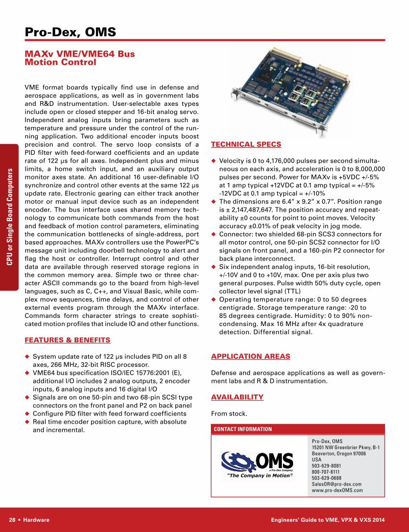
28 • Hardware Engineers’ Guide to VME, VPX & VXS 2014
ContaCt InformatIon
Pro-Dex, OMS
Pro-Dex, oMs15201 nW Greenbrier Pkwy, B-1Beaverton, oregon 97006 UsA503-629-8081800-707-8111503-629-0688salesoR@pro-dex.comwww.pro-dexoMs.com
TEChnICAl SPECS
◆ Velocity is 0 to 4,176,000 pulses per second simulta-neous on each axis, and acceleration is 0 to 8,000,000 pulses per second. Power for MAXv is +5VDC +/-5% at 1 amp typical +12VDC at 0.1 amp typical = +/-5% -12VDC at 0.1 amp typical = +/-10%
◆ The dimensions are 6.4” x 9.2” x 0.7”. Position range is ± 2,147,487,647. The position accuracy and repeat-ability ±0 counts for point to point moves. Velocity accuracy ±0.01% of peak velocity in jog mode.
◆ Connector: two shielded 68-pin SCS3 connectors for all motor control, one 50-pin SCS2 connector for I/O signals on front panel, and a 160-pin P2 connector for back plane interconnect.
◆ Six independent analog inputs, 16-bit resolution, +/-10V and 0 to +10V, max. One per axis plus two general purposes. Pulse width 50% duty cycle, open collector level signal (TTL)
◆ Operating temperature range: 0 to 50 degrees centigrade. Storage temperature range: -20 to 85 degrees centigrade. Humidity: 0 to 90% non-condensing. Max 16 MHz after 4x quadrature detection. Differential signal.
APPlICATIOn AREAS
Defense and aerospace applications as well as govern-ment labs and R & D instrumentation.
AVAIlABIlITy
From stock.
MAXv VME/VME64 Bus Motion Control
VME format boards typically find use in defense and aerospace applications, as well as in government labs and R&D instrumentation. User-selectable axes types include open or closed stepper and 16-bit analog servo. Independent analog inputs bring parameters such as temperature and pressure under the control of the run-ning application. Two additional encoder inputs boost precision and control. The servo loop consists of a PID filter with feed-forward coefficients and an update rate of 122 µs for all axes. Independent plus and minus limits, a home switch input, and an auxiliary output monitor axes state. An additional 16 user-definable I/O synchronize and control other events at the same 122 µs update rate. Electronic gearing can either track another motor or manual input device such as an independent encoder. The bus interface uses shared memory tech-nology to communicate both commands from the host and feedback of motion control parameters, eliminating the communication bottlenecks of single-address, port based approaches. MAXv controllers use the PowerPC’s message unit including doorbell technology to alert and flag the host or controller. Interrupt control and other data are available through reserved storage regions in the common memory area. Simple two or three char-acter ASCII commands go to the board from high-level languages, such as C, C++, and Visual Basic, while com-plex move sequences, time delays, and control of other external events program through the MAXv interface. Commands form character strings to create sophisti-cated motion profiles that include IO and other functions.
FEATURES & BEnEFITS
◆ System update rate of 122 µs includes PID on all 8 axes, 266 MHz, 32-bit RISC processor.
◆ VME64 bus specification ISO/IEC 15776:2001 (E), additional I/O includes 2 analog outputs, 2 encoder inputs, 6 analog inputs and 16 digital I/O
◆ Signals are on one 50-pin and two 68-pin SCSI type connectors on the front panel and P2 on back panel
◆ Configure PID filter with feed forward coefficients◆ Real time encoder position capture, with absolute
and incremental.
CPU or Single B
oard Computers CP
U o
r Sin
gle
Boa
rd C
ompu
ters
TM
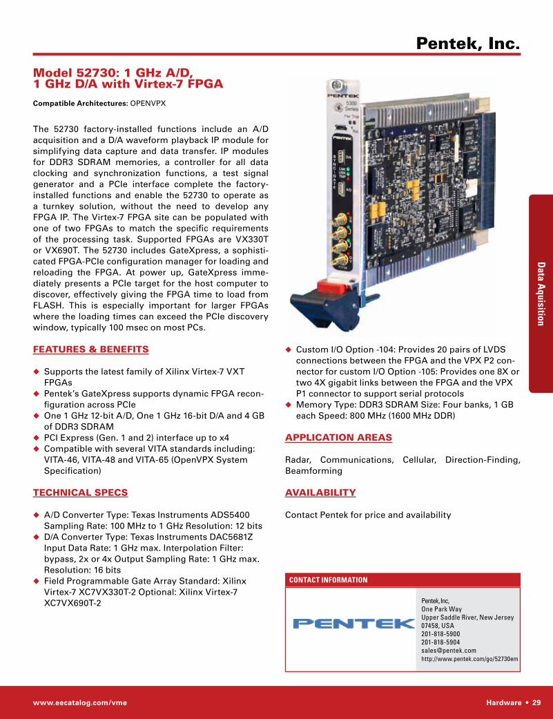
www.eecatalog.com/vme Hardware • 29
ContaCt InformatIon
◆ Custom I/O Option -104: Provides 20 pairs of LVDS connections between the FPGA and the VPX P2 con-nector for custom I/O Option -105: Provides one 8X or two 4X gigabit links between the FPGA and the VPX P1 connector to support serial protocols
◆ Memory Type: DDR3 SDRAM Size: Four banks, 1 GB each Speed: 800 MHz (1600 MHz DDR)
APPlICATIOn AREAS
Radar, Communications, Cellular, Direction-Finding, Beamforming
AVAIlABIlITy
Contact Pentek for price and availability
Model 52730: 1 Ghz A/D, 1 Ghz D/A with Virtex-7 FPGA Compatible Architectures: OPENVPX
The 52730 factory-installed functions include an A/D acquisition and a D/A waveform playback IP module for simplifying data capture and data transfer. IP modules for DDR3 SDRAM memories, a controller for all data clocking and synchronization functions, a test signal generator and a PCIe interface complete the factory-installed functions and enable the 52730 to operate as a turnkey solution, without the need to develop any FPGA IP. The Virtex-7 FPGA site can be populated with one of two FPGAs to match the specific requirements of the processing task. Supported FPGAs are VX330T or VX690T. The 52730 includes GateXpress, a sophisti-cated FPGA-PCIe configuration manager for loading and reloading the FPGA. At power up, GateXpress imme-diately presents a PCIe target for the host computer to discover, effectively giving the FPGA time to load from FLASH. This is especially important for larger FPGAs where the loading times can exceed the PCIe discovery window, typically 100 msec on most PCs.
FEATURES & BEnEFITS
◆ Supports the latest family of Xilinx Virtex-7 VXT FPGAs
◆ Pentek’s GateXpress supports dynamic FPGA recon-figuration across PCIe
◆ One 1 GHz 12-bit A/D, One 1 GHz 16-bit D/A and 4 GB of DDR3 SDRAM
◆ PCI Express (Gen. 1 and 2) interface up to x4 ◆ Compatible with several VITA standards including:
VITA-46, VITA-48 and VITA-65 (OpenVPX System Specification)
TEChnICAl SPECS
◆ A/D Converter Type: Texas Instruments ADS5400 Sampling Rate: 100 MHz to 1 GHz Resolution: 12 bits
◆ D/A Converter Type: Texas Instruments DAC5681Z Input Data Rate: 1 GHz max. Interpolation Filter: bypass, 2x or 4x Output Sampling Rate: 1 GHz max. Resolution: 16 bits
◆ Field Programmable Gate Array Standard: Xilinx Virtex-7 XC7VX330T-2 Optional: Xilinx Virtex-7 XC7VX690T-2
Data a
quisition Dat
a a
quis
ition
Pentek, Inc.
Pentek, Inc, one Park WayUpper saddle River, new Jersey07458, [email protected]://www.pentek.com/go/52730em
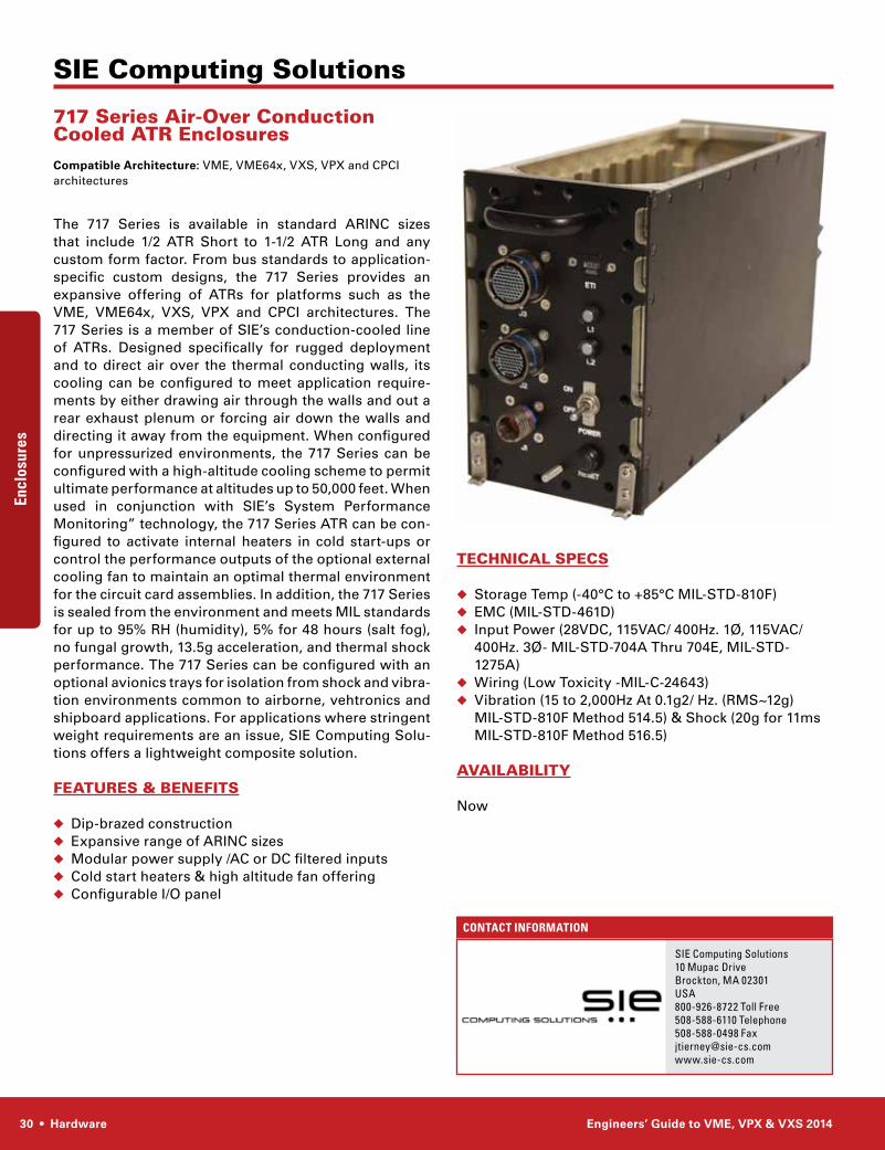
30 • Hardware Engineers’ Guide to VME, VPX & VXS 2014
ContaCt InformatIon
SIE Computing Solutions
sIe Computing solutions10 Mupac DriveBrockton, MA 02301UsA800-926-8722 toll Free508-588-6110 telephone508-588-0498 [email protected]
TEChnICAl SPECS
◆ Storage Temp (-40°C to +85°C MIL-STD-810F)◆ EMC (MIL-STD-461D)◆ Input Power (28VDC, 115VAC/ 400Hz. 1Ø, 115VAC/
400Hz. 3Ø- MIL-STD-704A Thru 704E, MIL-STD-1275A)
◆ Wiring (Low Toxicity -MIL-C-24643)◆ Vibration (15 to 2,000Hz At 0.1g2/ Hz. (RMS~12g)
MIL-STD-810F Method 514.5) & Shock (20g for 11ms MIL-STD-810F Method 516.5)
AVAIlABIlITy
Now
717 Series Air-Over Conduction Cooled ATR EnclosuresCompatible Architecture: VME, VME64x, VXS, VPX and CPCI architectures
The 717 Series is available in standard ARINC sizes that include 1/2 ATR Short to 1-1/2 ATR Long and any custom form factor. From bus standards to application-specific custom designs, the 717 Series provides an expansive offering of ATRs for platforms such as the VME, VME64x, VXS, VPX and CPCI architectures. The 717 Series is a member of SIE’s conduction-cooled line of ATRs. Designed specifically for rugged deployment and to direct air over the thermal conducting walls, its cooling can be configured to meet application require-ments by either drawing air through the walls and out a rear exhaust plenum or forcing air down the walls and directing it away from the equipment. When configured for unpressurized environments, the 717 Series can be configured with a high-altitude cooling scheme to permit ultimate performance at altitudes up to 50,000 feet. When used in conjunction with SIE’s System Performance Monitoring” technology, the 717 Series ATR can be con-figured to activate internal heaters in cold start-ups or control the performance outputs of the optional external cooling fan to maintain an optimal thermal environment for the circuit card assemblies. In addition, the 717 Series is sealed from the environment and meets MIL standards for up to 95% RH (humidity), 5% for 48 hours (salt fog), no fungal growth, 13.5g acceleration, and thermal shock performance. The 717 Series can be configured with an optional avionics trays for isolation from shock and vibra-tion environments common to airborne, vehtronics and shipboard applications. For applications where stringent weight requirements are an issue, SIE Computing Solu-tions offers a lightweight composite solution.
FEATURES & BEnEFITS
◆ Dip-brazed construction◆ Expansive range of ARINC sizes◆ Modular power supply /AC or DC filtered inputs◆ Cold start heaters & high altitude fan offering◆ Configurable I/O panel
EnclosuresEncl
osur
es
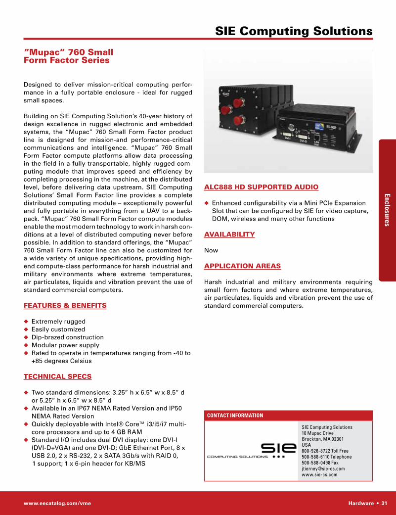
www.eecatalog.com/vme Hardware • 31
ContaCt InformatIon
SIE Computing Solutions
sIe Computing solutions10 Mupac DriveBrockton, MA 02301UsA800-926-8722 toll Free508-588-6110 telephone508-588-0498 [email protected]
AlC888 hD SUPPORTED AUDIO
◆ Enhanced configurability via a Mini PCIe Expansion Slot that can be configured by SIE for video capture, DOM, wireless and many other functions
AVAIlABIlITy
Now
APPlICATIOn AREAS
Harsh industrial and military environments requiring small form factors and where extreme temperatures, air particulates, liquids and vibration prevent the use of standard commercial computers.
“Mupac” 760 Small Form Factor Series
Designed to deliver mission-critical computing perfor-mance in a fully portable enclosure - ideal for rugged small spaces.
Building on SIE Computing Solution’s 40-year history of design excellence in rugged electronic and embedded systems, the “Mupac” 760 Small Form Factor product line is designed for mission-and performance-critical communications and intelligence. “Mupac” 760 Small Form Factor compute platforms allow data processing in the field in a fully transportable, highly rugged com-puting module that improves speed and efficiency by completing processing in the machine, at the distributed level, before delivering data upstream. SIE Computing Solutions’ Small Form Factor line provides a complete distributed computing module – exceptionally powerful and fully portable in everything from a UAV to a back-pack. “Mupac” 760 Small Form Factor compute modules enable the most modern technology to work in harsh con-ditions at a level of distributed computing never before possible. In addition to standard offerings, the “Mupac” 760 Small Form Factor line can also be customized for a wide variety of unique specifications, providing high-end compute-class performance for harsh industrial and military environments where extreme temperatures, air particulates, liquids and vibration prevent the use of standard commercial computers.
FEATURES & BEnEFITS
◆ Extremely rugged◆ Easily customized◆ Dip-brazed construction◆ Modular power supply◆ Rated to operate in temperatures ranging from -40 to
+85 degrees Celsius
TEChnICAl SPECS
◆ Two standard dimensions: 3.25” h x 6.5” w x 8.5” d or 5.25” h x 6.5” w x 8.5” d
◆ Available in an IP67 NEMA Rated Version and IP50 NEMA Rated Version
◆ Quickly deployable with Intel® Core™ i3/i5/i7 multi-core processors and up to 4 GB RAM
◆ Standard I/O includes dual DVI display: one DVI-I (DVI-D+VGA) and one DVI-D; GbE Ethernet Port, 8 x USB 2.0, 2 x RS-232, 2 x SATA 3Gb/s with RAID 0,
1 support; 1 x 6-pin header for KB/MS
EnclosuresEncl
osur
es
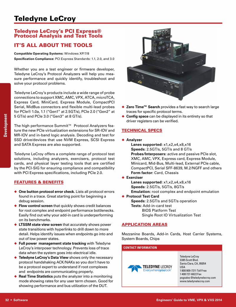
32 • Software Engineers’ Guide to VME, VPX & VXS 2014
ContaCt InformatIon
Developm
entDev
elop
men
t
◆ Zero Time™ Search provides a fast way to search large traces for specific protocol terms.
◆ Config space can be displayed in its entirety so that driver registers can be verified.
TEChnICAl SPECS
◆ Analyzer Lanes supported: x1,x2,x4,x8,x16 Speeds: 2.5GT/s, 5GT/s and 8 GT/s Probes/Interposers: active and passive PCIe slot, XMC, AMC, VPX, Express card, Express Module,
Minicard, Mid-Bus, Multi-lead, External PCIe cable, CompactPCI, Serial SFF-8639, M.2/NGFF and othersForm factor: Card, Chassis
◆ Exerciser Lanes supported: x1,x2,x4,x8,x16 Speeds: 2.5GT/s, 5GT/s, 8GT/s Emulation: root complex and endpoint emulation◆ Protocol Test Card Speeds: 2.5GT/s and 5GT/s operation Tests: Add-in-card test BIOS Platform Test Single Root IO Virtualization Test
APPlICATIOn AREAS
Mezzanine Boards, Add-in Cards, Host Carrier Systems, System Boards, Chips
Teledyne leCroy’s PCI Express® Protocol Analysis and Test Tools
IT’S All ABOUT ThE TOOlSCompatible Operating Systems: Windows XP/7/8
Specification Compliance: PCI Express Standards: 1.1, 2.0, and 3.0
Whether you are a test engineer or firmware developer, Teledyne LeCroy’s Protocol Analyzers will help you mea-sure perfor mance and quickly identify, troubleshoot and solve your protocol problems.
Teledyne LeCroy’s products include a wide range of probe connec tions to support XMC, AMC, VPX, ATCA, microTCA, Express Card, MiniCard, Express Module, CompactPCI Serial, MidBus connectors and flexible multi-lead probes for PCIe® 1.0a, 1.1 (“Gen1” at 2.5GT/s), PCIe 2.0 (“Gen2” at 5 GT/s) and PCIe 3.0 (“Gen3” at 8 GT/s).
The high performance Summit™ Protocol Ana lyzers fea-ture the new PCIe virtualization extensions for SR-IOV and MR-IOV and in-band logic analysis. Decoding and test for SSD drive/devices that use NVM Express, SCSI Express and SATA Express are also supported.
Teledyne LeCroy offers a complete range of protocol test solutions, including analyzers, exercisers, protocol test cards, and physical layer testing tools that are certified by the PCI-SIG for ensuring compliance and compatibility with PCI Express specifications, including PCIe 2.0.
FEATURES & BEnEFITS
◆ One button protocol error check. Lists all protocol errors found in a trace. Great starting point for beginning a debug session.
◆ Flow control screen that quickly shows credit balances for root complex and endpoint performance bottlenecks. Easily find out why your add-in card is underperforming on its benchmarks.
◆ LTSSM state view screen that accurately shows power state transitions with hyperlinks to drill down to more detail. Helps identify issues when endpoints go into and out of low power states.
◆ Full power management state tracking with Teledyne LeCroy’s interposer technology. Prevents loss of trace data when the system goes into electrical idle.
◆ Teledyne LeCroy’s Data View shows only the necessary protocol handshaking ACK/NAKs so you don’t have to be a protocol expert to understand if root complexes and endpoints are communicating properly.
◆ Real Time Statistics puts the analyzer into a monitoring mode showing rates for any user term chosen. Good for showing performance and bus utilization of the DUT.
teledyne LeCroy3385 scott Blvd.santa Clara, CA, 95054UsA1 800 909-7211 toll Free1 408 727-6622 Faxpsgsales @teledynelecroy.comwww.teledynelecroy.com
Teledyne leCroy
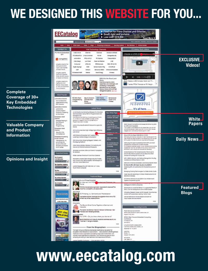
Opinions and Insight
FeaturedBlogs
Valuable Companyand ProductInformation
Complete Coverage of 30+ Key Embedded Technologies
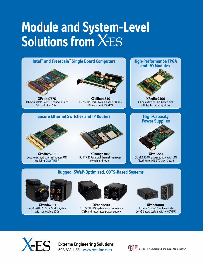
Designed, manufactured, and supported in the USA
Extreme Engineering Solutions608.833.1155 www.xes-inc.com
Module and System-Level Solutions from
Rugged, SWaP-Optimized, COTS-Based Systems
XPand4200Sub-½ ATR, 6x 3U VPX slot system
with removable SSDs
XPand6000SFF Intel® Core™ i7 or Freescale
QorIQ-based system with XMC/PMC
XPand6200SFF 2x 3U VPX system with removable
SSD and integrated power supply
Intel® and Freescale™ Single Board Computers
Secure Ethernet Switches and IP Routers
XPedite75704th Gen Intel® Core™ i7-based 3U VPX
SBC with XMC/PMC
XPedite5205Secure Gigabit Ethernet router XMC
utilizing Cisco™ IOS®
XCalibur1840Freescale QorIQ T4240-based 6U VPX
SBC with dual XMC/PMC
XChange30183U VPX 10 Gigabit Ethernet managed
switch and router
High-Performance FPGA and I/O Modules
High-Capacity Power Supplies
XPedite2400Xilinx Virtex-7 FPGA-based XMC
with high-throughput DAC
XPm22203U VPX 300W power supply with EMI
filtering for MIL-STD-704 & 1275