UNICO - DjangoBooks.com · Please read this manual carefully before operating the UNICO. Keep the...
12
UNICO
-
Upload
hoanghuong -
Category
Documents
-
view
216 -
download
0
Transcript of UNICO - DjangoBooks.com · Please read this manual carefully before operating the UNICO. Keep the...

UNICO

Please read this manual carefully before operating the UNICO. Keep the manual for future reference.Pay due care not to pour liquids on the device, nor operate it in excessively humid conditions.Do not install the UNICO near sorces of intense heat, expose it to direct sunlight, nor position it in dusty evironmentswithout protection. Ensure that the supply voltage is not higher than the one stated on the Rear Panel.To prevent any induced disturbance in the UNICO, do not install near transformers, TV sets, RF transmitters, electricmotors or any source of electric power.Never use the equipment if the cable or the electrical plug is damaged (if necessary change them or have them careful-ly repaired). Do not direct the microphones towards the speakers as this could cause acoustic feedback wich could damage the loud-speakers.To avoid damage, only use the original connection cables. Never connect any output and input channels of the device. It could create dangerous loops.Never use solvent based cleaning agents, such as acetone or alcohol to clean the equipment, as this will damage theexternal finish and the printing on the panels. In case of malfunction of any device in the system, contact the nearest SCHERTLER® technical assistance or a speciali-zed center. Do not attempt repairs yourself.
After two years spent monitoring the market, SCHERTLER® decided to improve the already successful Unicoto meet our users’ needs even more effectively. Unico has made its success through its versatility and mat-chless natural sound. Now, we have further increased the amplifier’s flexibility, adding some important fun-ctions. By changing the size and shape of the amplifier, we have achieved a tighter, more focused bassresponse. We have introduced a gain control function across the channels for improved input level control –this is vital for a clean signal. Individual channel gain controls allow maximum flexibility to easily matchvarious input signals. Mid control has been added to the DYN and STAT channels and a four-band equalizer isnow available in the MIC channel to suit the needs of demanding musicians. More compact and lighter, nowUnico is even easier to carry!
150W + 35W RMS, in combination with a biamplified system, guarantee total transparency, harmonically richsound and full low frequency control (down to 40Hz).
Compare Unico with the competition and you will appreciate the dif ference!
The SCHERTLER® Team.
WARNING
----
--
-
-
---
-
INTRODUCTION
PAGE1

PAGE2
OVERVIEW
1.1.
1.3.
1.2.
1.4.
1.5.
1.6.
2.1.
2.3.
2.2.
2.4.
2.6.
2.7.
3.1.
3.3.
3.2.
3.4.
3.6.
3.7.
4.1.
4.2.
4.3.
4.4.
4.8.
4.9.
2.5. 3.5.
4.5.
4.6.
4.7.
5.5. 5.1. 5.2. 5.4.5.3.
REAR PANEL
1.0. 2.0. 3.0. 4.0.
5.0.

MIC CHANNEL: This channel enables the connection of a condenser microphone, by activating the 48V button – or dynamic microphone.
STAT CHANNEL: This channel enables, for example, the connection of a guitar equipped with a BLUESTiCK® series system.
DYN CHANNEL: This channel enables, for example, the connection of a BASIK electrostatic microphone to amplify just any acoustic instrument.
INSERT: For easier volume control, you can use the “UNICO VOLUME CONTROL PEDAL” via the INSERT function.AUX SEND: For increased volume or wider coverage o, connect an active (powered) extension speaker such as the SCHERTLER SIDE(180W) or PUB 280 (280 W) active loudspeaker and adjust output volume using the AUX SEND potentiometer. Alternatively, if youwish to record your music, connect your recorder to the same output and start recording.
DI OUT: Signal can be sent to another mixer, for example SCHERTLER’s OPERA mixer.
LINE OUT: For use with bass or keyboards or to increse overall bass response, SCHERTLER® strongly recommends the use of a sub-
woofer such as the SCHERTLER® BASS200 or PUB380. Connect the LINE OUT to the INPUT of the sub-woofer, press the LOW CUT on
the UNICO, for a three-way (triamplified) system.
CONNECTING YOUR BLUESTICKAll BLUESTiCK® models (except for MARINE series) can be connected to STAT and DYN inputs with the 10V switch OFF. BLUESTiCK® MARINE: Connect to STAT input with the 10V switch ON.
CONNECTING HIGH-IMPEDANCE SIGNALS (piezos, magnetic pick-ups and similar sources)To connect any passive piezo transducer or magnetic pick-up, use “Active Driver Cable” and connect to the STAT input withthe 10V switch ON. The high-impedance cable is also used to connect electric guitars and bass guitars with magnetic pick-ups.Product order code: CA-ADRIVER-4
1.
2.
3.
4.5.
6.7.
1. condenser mic2. Guitar with the Bluestick3.
BASIK
ellec
trosta
ticmi
c.
4. Volume pedal - UNI-PED
5. Supporto monito
r SIDE (180W)
6. Opera mixer or other boards
7. Active bass extension (BASS200/PUB380)
UNICO
UTILITIES
PAGE3
EXAMPLE 1
PAGE4
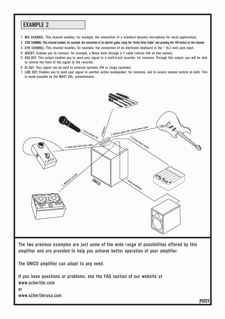
MIC CHANNEL: This channel enables, for example, the connection of a standard dynamic microphone for vocal applications.
STAT CHANNEL: This channel enables, for example, the connection of an electric guitar, using the “Active Drive Cable” and pressing the 10V button on the channel.
DYN CHANNEL: This channel enables, for example, the connection of an electronic keyboard in the “ (6.3 mm) jack input.
INSERT: Enables you to connect, for example, a Noise Gate through a Y cable (stereo link on two monos).AUX OUT: This output enables you to send your signal to a multi-track recorder, for instance. Through this output, you will be ableto control the level of the signal to the recorder.
DI OUT: Your signal can be sent to external systems (PA or stage systems).LINE OUT: Enables you to send your signal to another active loudspeaker, for instance, and to ensure volume control on both. Thisis made possible by the MAST VOL. potentiometer.
1.
2.
3.
4.5.
6.7.
UNICO
2. Ellectric guitar with “Active Driver Cable”
3.Ke
yboa
rd
1. Vocal dynamic mic
4. Noise Gate with insert cable
5. Multi
track
record
er
6. External board (mixer)
7. Active loudspeaker
EXAMPLE 2
The two previous examples are just some of the wide range of possibilities offered by thisamplifier and are provided to help you achieve better operation of your amplifier.
The UNICO amplifier can adapt to any need.
If you have questions or problems, see the FAQ section of our website at www.schertler.com orwww.schertlerusa.com
1.0. MIC
PAGE5
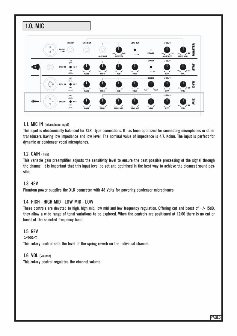
1.1. MIC IN (microphone input)
This input is electronically balanced for XLR - type connections. It has been optimized for connecting microphones or othertransducers having low impedance and low level. The nominal value of impedance is 4.7. Kohm. The input is perfect fordynamic or condenser vocal microphones.
1.2. GAIN (Trim)
This variable gain preamplifier adjusts the sensitivity level to ensure the best possible processing of the signal throughthe channel. It is important that this input level be set and optimised in the best way to achieve the cleanest sound pos-sible.
1.3. 48VPhantom power supplies the XLR connector with 48 Volts for powering condenser microphones.
1.4. HIGH - HIGH MID - LOW MID - LOWThese controls are devoted to high, high mid, low mid and low frequency regulation. Offering cut and boost of +/- 15dB,they allow a wide range of tonal variations to be explored. When the controls are positioned at 12:00 there is no cut orboost of the selected frequency band.
1.5. REV
This rotary control sets the level of the spring reverb on the individual channel.
1.6. VOL (Volume)
This rotary control regulates the channel volume.

2.1. DYN IN (Combo connector XLR or 1/4” Jack)
This input is electronically balanced for XLR - type connections and unbalanced for 1/4” Jack type connections. It has been opti-mized for connecting microphones or other transducers having low impedance and low level. The nominal value of impedanceis 10Kohm. The 10V phantom power switch supplies the Jack input and may be used for the electrostatic condenser micropho-nes with low sensitivity. This input is also designned for electrodynamic microphones such as Schertler DYN-series transducers.
2.2. GAIN (Trim)
This variable gain preamplifier adjusts the sensitivity level to ensure the best possible processing of the signal throughthe channel. It is important that this input level be set and optimised in the best way to achieve the cleanest sound pos-sible.
2.3. 10VPhantom power supplies the jack connector with 10 Volts for powering electret microphones.
2.4. HIGH - MID - LOWThese controls are devoted to high, mid and low frequency regulation. Offering cut and boost of +/- 15dB, they allow awide range of tonal variations to be explored. When the controls are positioned dentrally there is no cut or boost of theselected frequency band.
2.5. RESON (Resonance)
The Resonance (notch) filter attenuates (cuts) the frequency of 180Hz, to reduce low-frequency feedback.- Left: no attenuation (flat)- Right: maximum attenuation
2.6. REV
This rotary control sets the level of the spring reverb on the individual channel.
2.7. VOL (Volume)
This rotary control regulates the channel volume.
2.0. DYN
PAGE6

3.0. STAT
PAGE7
3.1. STAT IN (Input)
Unbalanced input for the connection of (6.3mm or 1/4”) jacks, high input impedance and optimal sensitivity for high levelsignals such as: audio players, active electric bass, guitars, keyboards, etc. Nominal input impedance is 100 Kohm. Allof Schertler’s STAT, BASIK and MARINE-series models and any type of electrostatic microphone can be used directly inthis input without preamplifier. Through this input, it is also possible to connect all passive piezoelectric sources usingthe “Active Driver Cable” (which you will find in our product list) – simply by pressing the 10 V button.
3.2. GAIN (Trim)
This variable gain preamplifier adjusts the sensitivity level to ensure the best possible processing of the signal throughthe channel. It is important that this input level be set and optimised in the best way to achieve the cleanest sound pos-sible.
3.3. 10VPhantom power supplies the (6.3mm or 1/4”) Jack connector with 10 Volts for powering electret microphones microphones.
3.4. HIGH - MID - LOWThese controls are devoted to high, mid and low frequency regulation. Offering cut and boost of +/- 15dB, they allow awide range of tonal variations to be explored. When the controls are positioned at 12:00 there is no cut or boost of theselected frequency band.
3.5. WARMWhen engaged, this low-pass filter damps higher frequencies to produce a warmer sound when using bridge-mounted pic-kups such as Schertler STAT-series transducers for violin, cello and doublebass.
3.6. REV
This rotary control sets the level of the spring reverb on the individual channel.
3.7. VOL (Volume)
This rotary control regulates the channel volume.
4.0. MASTER SECTION
PAGE8
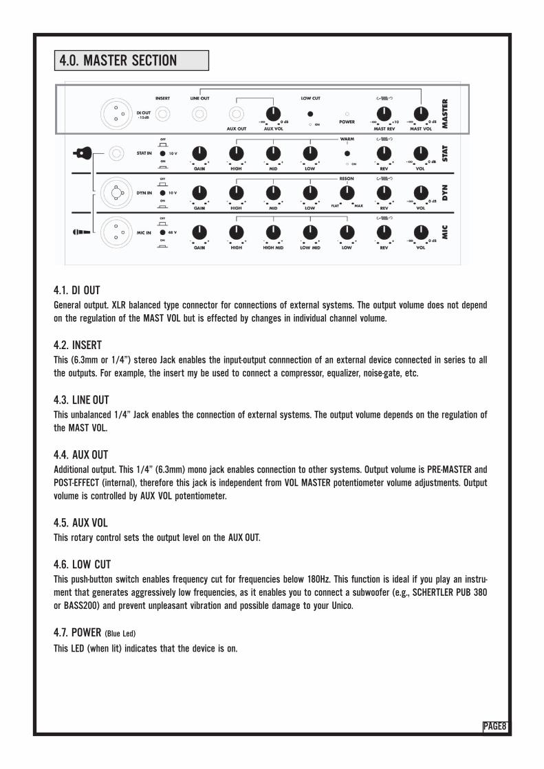
4.1. DI OUTGeneral output. XLR balanced type connector for connections of external systems. The output volume does not dependon the regulation of the MAST VOL but is effected by changes in individual channel volume.
4.2. INSERTThis (6.3mm or 1/4”) stereo Jack enables the input-output connnection of an external device connected in series to allthe outputs. For example, the insert my be used to connect a compressor, equalizer, noise-gate, etc.
4.3. LINE OUTThis unbalanced 1/4” Jack enables the connection of external systems. The output volume depends on the regulation ofthe MAST VOL.
4.4. AUX OUTAdditional output. This 1/4” (6.3mm) mono jack enables connection to other systems. Output volume is PRE-MASTER andPOST-EFFECT (internal), therefore this jack is independent from VOL MASTER potentiometer volume adjustments. Outputvolume is controlled by AUX VOL potentiometer.
4.5. AUX VOLThis rotary control sets the output level on the AUX OUT.
4.6. LOW CUTThis push-button switch enables frequency cut for frequencies below 180Hz. This function is ideal if you play an instru-ment that generates aggressively low frequencies, as it enables you to connect a subwoofer (e.g., SCHERTLER PUB 380or BASS200) and prevent unpleasant vibration and possible damage to your Unico.
4.7. POWER (Blue Led)
This LED (when lit) indicates that the device is on.
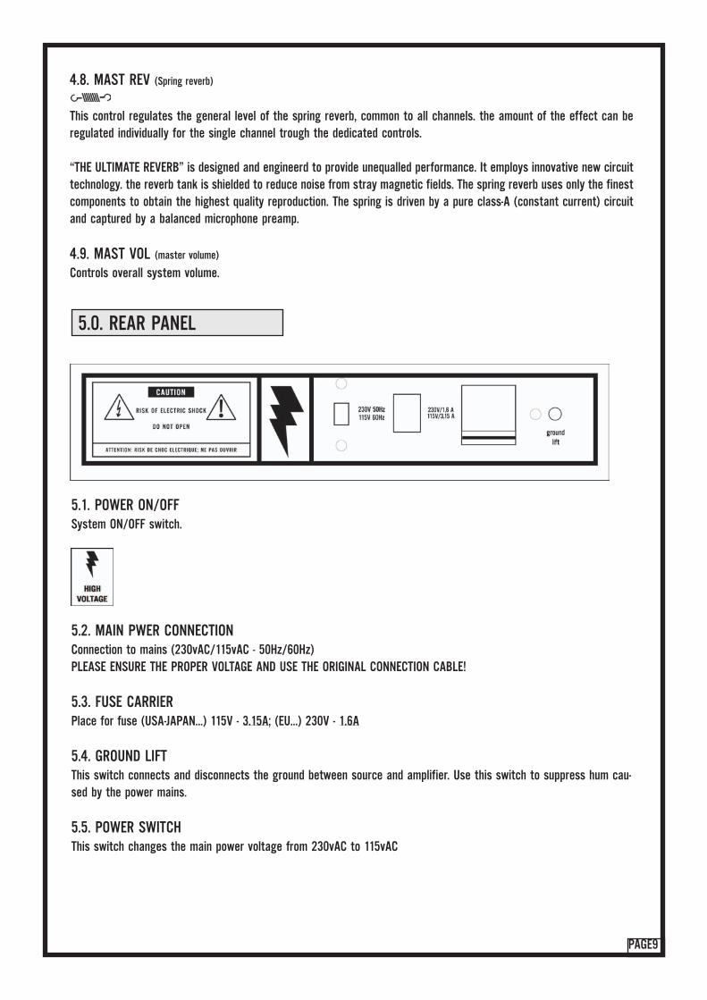
5.0. REAR PANEL
PAGE9
4.8. MAST REV (Spring reverb)
This control regulates the general level of the spring reverb, common to all channels. the amount of the effect can beregulated individually for the single channel trough the dedicated controls.
“THE ULTIMATE REVERB” is designed and engineerd to provide unequalled performance. It employs innovative new circuittechnology. the reverb tank is shielded to reduce noise from stray magnetic fields. The spring reverb uses only the finestcomponents to obtain the highest quality reproduction. The spring is driven by a pure class-A (constant current) circuitand captured by a balanced microphone preamp.
4.9. MAST VOL (master volume)
Controls overall system volume.
5.1. POWER ON/OFFSystem ON/OFF switch.
5.2. MAIN PWER CONNECTIONConnection to mains (230vAC/115vAC - 50Hz/60Hz)PLEASE ENSURE THE PROPER VOLTAGE AND USE THE ORIGINAL CONNECTION CABLE!
5.3. FUSE CARRIERPlace for fuse (USA-JAPAN...) 115V - 3.15A; (EU...) 230V - 1.6A
5.4. GROUND LIFTThis switch connects and disconnects the ground between source and amplifier. Use this switch to suppress hum cau-sed by the power mains.
5.5. POWER SWITCH This switch changes the main power voltage from 230vAC to 115vAC

PAGE10
6.0. TECHNICAL DESCRIPTION
DESCRIPTIONBox two way, bass reflex
ENCLOSURE SECTIONConstruction - PlywoodWeight - 14.4 KgDimensions - 33cm x 39cm x 29cm
AMPLIFIED SPEAKER SECTIONFrequency resp. - 40Hz - 22KHzSensitivity - (1W-1m) 93dBSPL max - 112dB
TECHNICAL SPECIFICATIONS INPUTSMIC:Connector - XLR balancedSensitivity - 0dB to -40dBImpedance - 4.7KohmDYN:Connector - XLR balanced, JACK 6,3mm unbalancedSensitivity - +5dB to -35dBImpedance - 10KohmSTAT:Connector - JACK 6,3mm unbalancedSensitivity - +10dB to -30dBImpedance - 10Kohm
TECHNICAL SPECIFICATIONS OUTPUTSLINE OUT:Connector - JACK 6,3mm unbalancedSensitivity - -12dBImpedance - 200ohmDI OUT:Connector - XLR balancedSensitivity - -15dBImpedance - 200ohmAUX OUT:Connector - JACK 6,3mm balancedSensitivity - 0dB Impedance - 200ohm
INTERNAL EFFECT (spring reverb)Freuency resp. - 200Hz - 10KHzDelay Time - c.a. 30msReverb time - c.a. 2s
COMPONENTSWoofer - 8”Tweeter - DomeCross-over - Active, 24dB/octaveAmplifier - Biamplified 150W + 35W RMS power
- 0.1% THD- 8ohm- 320W Peak
INSERTJack Stereo - Unbalanced
TIP - sendRING - returnSLEEVE - ground
FUSE (slow type)
230V - 1.6A115V - 3.15A

TM
SCHERTLER SAVia Beroldingen 18,
6850 Mendrisio, Switzerlandt. +41 91 630 07 10f. +41 91 630 07 11
official web-page: www.schertler.comUSA web-page: www.schertlerusa.com
official e-mail: [email protected] e-mail: [email protected]