UNDERGROUND MINE VENTILATION SURVEY -...
68
UNDERGROUND MINE VENTILATION SURVEY A THESIS SUBMITTED IN PARTIAL FULLFILLMENT OF THE REQUIREMENTS FOR THE DEGREE OF Bachelor of Technology In Mining Engineering By ALOK RANJAN SETHI 111MN0403 DEPARTMENT OF MINING ENGINEERING NATIONAL INSTITUTE OF TECHNOLOGY ROURKELA – 769008 (2014 -2015)
Transcript of UNDERGROUND MINE VENTILATION SURVEY -...
UNDERGROUND MINE VENTILATION SURVEY
A THESIS SUBMITTED IN PARTIAL FULLFILLMENT OF THE
REQUIREMENTS FOR THE DEGREE OF
Bachelor of Technology
In
Mining Engineering
By
ALOK RANJAN SETHI
111MN0403
DEPARTMENT OF MINING ENGINEERING
NATIONAL INSTITUTE OF TECHNOLOGY
ROURKELA – 769008
(2014 -2015)
UNDERGROUND MINE VENTILATION SURVEY
A THESIS SUBMITTED IN PARTIAL FULLFILLMENT OF THE
REQUIREMENTS FOR THE DEGREE OF
Bachelor of Technology
In
Mining Engineering
By
ALOK RANJAN SETHI
111MN0403
Under the Guidance of
PROF. D. S. NIMAJE
DEPARTMENT OF MINING ENGINEERING
NATIONAL INSTITUTE OF TECHNOLOGY
ROURKELA – 769008
(2014 -2015)
i
National Institute of Technology
Rourkela
CERTIFICATE
This is to certify that the thesis entitled “UNDERGROUND MINE VENTILATION
SURVEY” submitted by Sri Alok Ranjan Sethi (Roll No. 111mn0403) in partial fulfilment
of the requirements for the award of Bachelor of Technology degree in Mining Engineering at
the National Institute of Technology, Rourkela is an authentic work carried out by him under
my supervision and guidance.
To the best of my knowledge, the matter embodied in the thesis has not been submitted to any
other University/Institute for the award of any Degree or Diploma.
Prof. D.S. Nimaje
Asst. Professor
Dept. of Mining Engineering
National Institute of Technology
Rourkela – 769 008
ii
ACKNOWLEDGEMENT
I wish to express my profound gratitude and indebtedness to Prof. D. S. Nimaje ,
Department of Mining Engineering, NIT Rourkela for introducing the present topic and
for his inspiring guidance, constructive criticism and valuable suggestion throughout the
project work.
I am thankful to Mr. A. A. Ansari , ventilation officer at the Nandira Colliery for helping
me in completion of my project work in all respects. I am also thankful to Mr. Sunil Kr
Singh, alumni of our department currently working as Assistant Manager at Nandira Colliery
for helping me with the instruments and permission, special thanks to my brother and parents
for their support and help in carrying out.
Alok Ranjan Sethi
iii
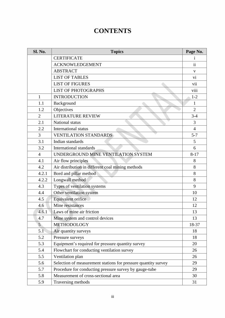
CONTENTS
Sl. No. Topics Page No.
CERTIFICATE i
ACKNOWLEDGEMENT ii
ABSTRACT v
LIST OF TABLES vi
LIST OF FIGURES vii
LIST OF PHOTOGRAPHS viii
1 INTRODUCTION 1-2
1.1 Background 1
1.2 Objectives 2
2 LITERATURE REVIEW 3-4
2.1 National status 3
2.2 International status 4
3 VENTILATION STANDARDS 5-7
3.1 Indian standards 5
3.2 International standards 6
4 UNDERGROUND MINE VENTILATION SYSTEM 8-17
4.1 Air flow principles 8
4.2 Air distribution in different coal mining methods 8
4.2.1 Bord and pillar method 8
4.2.2 Longwall method 8
4.3 Types of ventilation systems 9
4.4 Other ventilation system 10
4.5 Equivalent orifice 12
4.6 Mine resistances 12
4.6.1 Laws of mine air friction 13
4.7 Mine system and control devices 13
5 METHODOLOGY 18-37
5.1 Air quantity surveys 18
5.2 Pressure surveys 18
5.3 Equipment’s required for pressure quantity survey 20
5.4 Flowchart for conducting ventilation survey 26
5.5 Ventilation plan 26
5.6 Selection of measurement stations for pressure quantity survey 29
5.7 Procedure for conducting pressure survey by gauge-tube 29
5.8 Measurement of cross-sectional area 30
5.9 Traversing methods 31

iv
5.10 Survey records 35
5.11 Hygrometric surveys 35
5.12 Precautions during survey 37
6 RESULT AND ANALYSIS 38-54
6.1 Result 38
6.2 Analysis 46
7 CONCLUSIONS 55-56
7.1 Conclusions 55
7.2 Recommendations 56
REFERENCES 57
v
ABSTRACT
Underground coal mine ventilation systems are particularly complex because of multiple seam
working methods which splits the underground air network into different districts or/and panels
thereby allowing multiple ventilation methods. In order to gain an understanding of the
complex networks incorporated in the system, a coal mine ventilation survey is required. The
information obtained from this survey is used to determine the most efficient techniques to
accomplish any proposed improvements. The proper operation of the ventilation system at
maximum efficiency is essential for providing a safe and healthy underground working
environment. These systems should be designed to ensure that adequate amounts of ventilating
and numerous split air reach each working area. Most underground coal mines in India employ
an exhaust (i.e. negative pressure) ventilation system.
This project deals with the pressure and air quantity survey of an underground coal mine
ventilation system at Nandira colliery, Talcher. The survey work has been carried out with the
help of latest instruments at nearly forty stations. Methodology of the ventilation survey and
simulation of survey readings in VENTSIM has been demonstrated. Based on the simulation
result, analysis was done.
vi
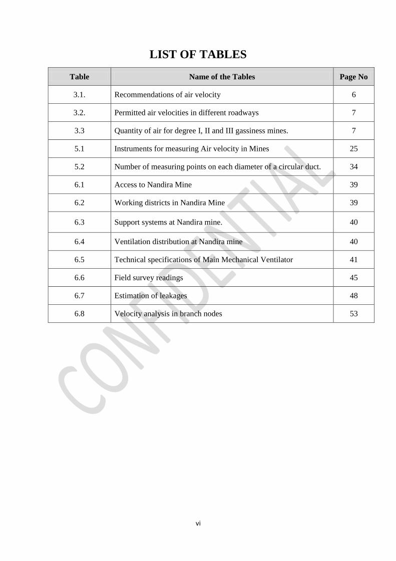
LIST OF TABLES
Table Name of the Tables Page No
3.1. Recommendations of air velocity 6
3.2. Permitted air velocities in different roadways 7
3.3 Quantity of air for degree I, II and III gassiness mines. 7
5.1 Instruments for measuring Air velocity in Mines 25
5.2 Number of measuring points on each diameter of a circular duct. 34
6.1 Access to Nandira Mine 39
6.2 Working districts in Nandira Mine 39
6.3 Support systems at Nandira mine. 40
6.4 Ventilation distribution at Nandira mine 40
6.5 Technical specifications of Main Mechanical Ventilator 41
6.6 Field survey readings 45
6.7 Estimation of leakages 48
6.8 Velocity analysis in branch nodes 53
vii
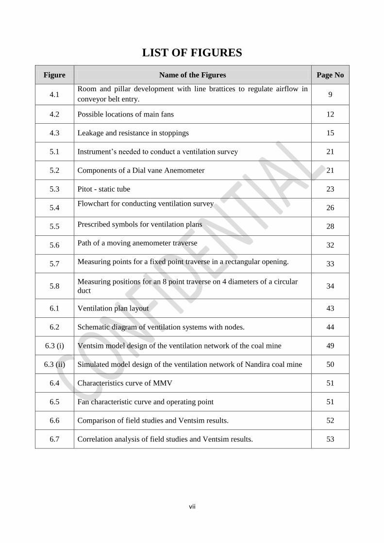
LIST OF FIGURES
Figure Name of the Figures Page No
4.1 Room and pillar development with line brattices to regulate airflow in
conveyor belt entry. 9
4.2 Possible locations of main fans 12
4.3 Leakage and resistance in stoppings 15
5.1 Instrument’s needed to conduct a ventilation survey 21
5.2 Components of a Dial vane Anemometer 21
5.3 Pitot - static tube 23
5.4 Flowchart for conducting ventilation survey
26
5.5 Prescribed symbols for ventilation plans 28
5.6 Path of a moving anemometer traverse 32
5.7 Measuring points for a fixed point traverse in a rectangular opening. 33
5.8 Measuring positions for an 8 point traverse on 4 diameters of a circular
duct 34
6.1 Ventilation plan layout 43
6.2 Schematic diagram of ventilation systems with nodes. 44
6.3 (i) Ventsim model design of the ventilation network of the coal mine 49
6.3 (ii) Simulated model design of the ventilation network of Nandira coal mine 50
6.4 Characteristics curve of MMV 51
6.5 Fan characteristic curve and operating point 51
6.6 Comparison of field studies and Ventsim results. 52
6.7 Correlation analysis of field studies and Ventsim results. 53

viii
LIST OF PHOTOGRAPHS
Plate No. Name of the Photographs Page No
5.1 Dial-vane anemometer 21
5.2 An inclined-tube manometer 22
5.3 Sling Psychrometer 24
6.1 Auxiliary Fan 42
1
CHAPTER 1
INTRODUCTION
1.1 BACKGROUND
In underground mines, production, productivity, health and safety of workers rely upon
environmental conditions existed at the work place. Polluted environment reduces the environment
efficiency of work persons and machinery which ultimately reflects on the economy of the mine.
Proper ventilation of mine workings can lead to safe and efficient operation in mines. So it’s
essential to conduct a ventilation survey at frequent intervals to monitor the change in
environmental conditions and improving it for working.
A ventilation survey is a framework of collecting data that measure the distributions of airflow,
pressure and air quality all through the principle stream ways of a ventilation framework which
involves a detailed precision of measurement. The examination is generally done for finding the
efficiency of a ventilation system, types and the extent of leakages and the steps indispensable for
further change. The types of ventilation surveys generally involves [13]
1. Quantity surveying: this involves the measurement of the air velocity and the quantity of
air flowing in various parts of the mine.
2. Pressure surveying: this involves the measurement of the differential pressure drop across
the branches in mine.
3. Qualitative surveying: this involves the determination of the free damp content at different
strategic points in the mine and chemical analysis of the air samples.
The importance of a systematic and regular ventilation survey provide the basis for:
(a) Checking and supply for adequate quantity of air to any working face most importantly in
hot, humid and gassy mines.
(b) Detecting and remedying leakages of air.
(c) Determining size of the airways and sections of high aerodynamic resistance
(d) Suggesting possible modifications and alterations in amount and path of air currents,
airways resistances, control devices for improving the ventilation efficiency in the mine.
2
(e) Planning suitable ventilation to control mine fires and with other emergencies such as
explosions, major falls etc.
(f) Planning future reorganizations of the ventilation system for extended/modified workings.
(g) To check the standard limits be well maintained for direction and quantity of air in the air
flows by the concerned authorities.
(h) Identifying suitable locations for installation of booster fans.
(i) Maintaining an uptodate plan.
1.2 OBJECTIVES
A major objective of ventilation surveys is to obtain the frictional pressure drop, P, and the
corresponding airflow, Q, for each of the main branches of the ventilation network. From these
data, the following parameters may be calculated for the purposes of both planning and control:
• Distribution of airflows, pressure drops and leakage
• Airpower (P x Q) losses and, hence, distribution of ventilation operating costs throughout
network
• Volumetric efficiency of the system
• Branch resistances (R = P / Q2)
• Simulating an effective model for the exiting ventilation system.
3
CHAPTER 2
LITERATURE REVIEW
2.1 INTERNATIONAL STATUS
Rowland (2011) have demonstrated the ventilation survey techniques and the execution of a
ventilation modelling out of the survey results and suggested some outputs for the same. He have
emphasized that the level of survey detail required is totally dependent on the end use of the data
and the accuracy of the data set for safety and viability of working operations. He formulates a
strategy to carry out the appropriate ventilation survey and highlights the nature of report outputs.
He had advocated for fabrication of a properly tuned ventilation model which are intricate
components of the modern underground safety management systems and emphasis for utilizing
the ventilation modelling software as a key tool in ventilation circuit designs and ventilation
changes.
Brian & Loomis (2004) have measured the frictional pressure differential during a ventilation
survey. They compares the two basic methods of frictional pressure drop measurements; the
barometer and the gauge & tube regarding applicability and conditions favoring each method and
believed that in both metal and coal mines the gauge & tube method is more preferable than the
barometric pressure techniques owing to rapid evaluation and more accurate results.
Hinsley (1966) demonstrated that when a ventilation system is changed from forcing to exhaust
the inbye portions of the workings are reduced below the barometric pressure of the air by an
amount equal to half the fan pressure.
Akande et al. (2013) developed a model for the calculation of mine airflow distribution as a part
of comprehensive study for underground coal mine of Okaba coal deposits. Calculated the air
pressure, fan power and airflow rate to maintain the safety levels of methane in underground mine
for workers protection against harmful substances.
Calizaya et al. (2010) computed quantity and pressure readings for monitoring and developing a
booster fan selection method.
4
2.2 NATIONAL STATUS
S K Ray et al. (2002) carried out pressure quantity survey on 1 & 2 incline of Jhanjhra area of
Raniganj coalfields at RVII & RVIIA seam by hose & trailing method, inclined manometer, pitot
tubes etc. and quantity by anemometer at more than 20 strategic locations to ascertain air quantity
distribution in mine for introducing a chamber method of ventilation arrangement which is
superimposed on main ventilator system to reduce cumulative pressure in a desired area without
affecting the main fan pressure and ventilation in other part of the mine.
Varma et al. (2009) conducted ventilation survey which comprises of pressure survey, quantity
survey, study of performance of main fan and fire area stoppings behaviour as a part of
investigation in Sindra Banjara colliery a unit of Sijua area, BCCL on VI seam of pit no.3.
Morla et al. (2012) presented a detailed case study of the pressure survey of the ventilation
network and the simulation results of the GDK-11 incline in RG-I area of SCCL for bord and pillar
mines with an objective of increasing the ventilation quantity with low operating pressure and
effective utilization of main mechanical ventilator and observed that, the alteration of the intake
air shaft into a return shaft will increase overall resistance of the mine.
Sahay et al. (2003) conducted pressure survey, air quantity survey, temperature survey,
performance study of fans, computer simulation studies and studied pressure behaviour of
stoppings at Kacchi Balihari colliery of Bharat Coking Coal Limited (BCCL), India for controlling
fire in the sealed panel.
5
CHAPTER 3
VENTILATION STANDARDS
3.1 INDIAN STANDARDS
The Indian Coal Mining Regulations (CMR-1957) [16], regulation no. 130 (2) requires that:
In every ventilating district no less than six cubic meters per minute of air per person
employed in the district on the largest shift, or no less than 2.5 cubic meters per minute of
air per minute of air per daily tonne output, whichever is larger passes along the last
ventilation connection in the district.
At every place in the mine where persons are required to work or pass, the air does not
contain less than 19% oxygen, and or more than 0.5% CO2 or any noxious gas in the
quantity likely to affect the health of any person.
The percentage of inflammable gas does not exceed 0.75 in the general body of the return
air of any ventilating district, and 1.25 in any place of the mine.
The wet bulb temperature in any working place does not exceed 33.50C, and where the wet
bulb temperature exceeds 30.50C, arrangements are made to ventilate the same with a
current of air moving at a speed of not less than one meter per second.
Indian mining laws sub regulation 133(4) of the CMR requires that ventilation surveys
be conducted in 1st degree-I gassy mines at least once every 30 days while air quantity
surveys in degree-II & degree-III gassy mines are required to be conducted at least once
every 14 days.
Sub regulation 130(2) (v) requires that concentration of noxious and inflammable gases
and temperature and humidity to be determined at the working places in mines at least once
in 30 days.
Under sub regulation 145(2), the Regional Inspector of mines may require the mine
management to take measurements of temperature, humidity and other environmental
conditions as may be specified once at least in every 30 days.
6
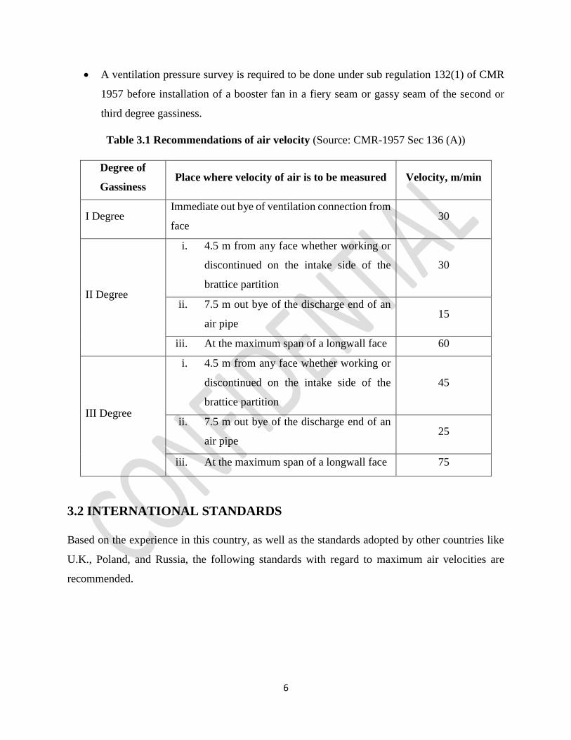
A ventilation pressure survey is required to be done under sub regulation 132(1) of CMR
1957 before installation of a booster fan in a fiery seam or gassy seam of the second or
third degree gassiness.
Table 3.1 Recommendations of air velocity (Source: CMR-1957 Sec 136 (A))
Degree of
Gassiness Place where velocity of air is to be measured Velocity, m/min
I Degree Immediate out bye of ventilation connection from
face 30
II Degree
i. 4.5 m from any face whether working or
discontinued on the intake side of the
brattice partition
30
ii. 7.5 m out bye of the discharge end of an
air pipe 15
iii. At the maximum span of a longwall face 60
III Degree
i. 4.5 m from any face whether working or
discontinued on the intake side of the
brattice partition
45
ii. 7.5 m out bye of the discharge end of an
air pipe 25
iii. At the maximum span of a longwall face 75
3.2 INTERNATIONAL STANDARDS
Based on the experience in this country, as well as the standards adopted by other countries like
U.K., Poland, and Russia, the following standards with regard to maximum air velocities are
recommended.
7
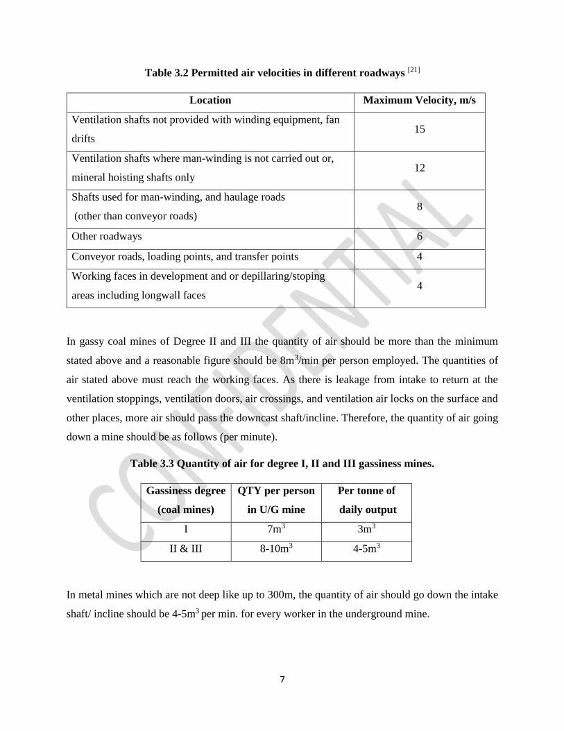
Table 3.2 Permitted air velocities in different roadways [21]
Location Maximum Velocity, m/s
Ventilation shafts not provided with winding equipment, fan
drifts 15
Ventilation shafts where man-winding is not carried out or,
mineral hoisting shafts only 12
Shafts used for man-winding, and haulage roads
(other than conveyor roads) 8
Other roadways 6
Conveyor roads, loading points, and transfer points 4
Working faces in development and or depillaring/stoping
areas including longwall faces 4
In gassy coal mines of Degree II and III the quantity of air should be more than the minimum
stated above and a reasonable figure should be 8m3/min per person employed. The quantities of
air stated above must reach the working faces. As there is leakage from intake to return at the
ventilation stoppings, ventilation doors, air crossings, and ventilation air locks on the surface and
other places, more air should pass the downcast shaft/incline. Therefore, the quantity of air going
down a mine should be as follows (per minute).
Table 3.3 Quantity of air for degree I, II and III gassiness mines.
Gassiness degree
(coal mines)
QTY per person
in U/G mine
Per tonne of
daily output
I 7m3 3m3
II & III 8-10m3 4-5m3
In metal mines which are not deep like up to 300m, the quantity of air should go down the intake
shaft/ incline should be 4-5m3 per min. for every worker in the underground mine.
8
CHAPTER 4
UNDERGROUND MINE VENTILATION SYSTEMS
4.1 AIR FLOW PRINCIPLES [3]
The fundamental principles of airflow may be set out as follows:
a. Air flow in a mine is induced by pressure difference between intake and exhaust openings.
b. The pressure difference is caused by imposing some form of pressure at one point or a series
of points in a ventilating system.
c. The pressure created must be great enough to overcome frictional resistance and shock losses.
d. Airflows flows from point of higher to lower pressure.
e. Mine ventilating pressures, with respect to atmospheric pressures, may either be positive
(forcing) or negative (exhausting).
4.2 AIR DISTRIBUTION IN DIFFERENT COAL MINING METHODS [2]
4.2.1 Bord and Pillar Method
There are a large number of openings in a working district in this method. As a result, the air has
to be guided to the working faces by means of numerous control devices such as stopping, doors
and air-crossings etc. Air is coursed through the different faces in the working panel with the help
of line brattices at the face and temporary stoppings generally made up of brattice curtains in the
galleries. However, this results in a substantial leakage through the brattice leading to poor face
air velocity. Panels separated by solid coal barriers reduce the number of permanent stoppings and
to that extent reduce the leakage.
4.2.2 Longwall Method
Ventilation of longwall faces is easier needing less control. Each face is normally ventilated by a
separate split. Leakage is much less in the working district as compared to bord and pillar mining.
Longwall workings with hydraulic stowing admit practically no leakage through the goaf, but there
is fair amount of leakage across the goaf in longwall caving districts, particularly with advancing
faces.
9
4.3 TYPES OF VENTILATION SYSTEMS
Depending on the relative position of intake and return airways, ventilation systems in mines can
be broadly divided into the following:
(a) (b)
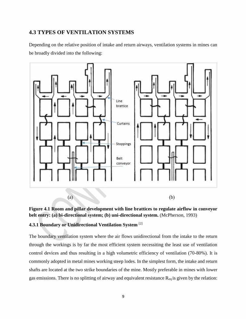
Figure 4.1 Room and pillar development with line brattices to regulate airflow in conveyor
belt entry: (a) bi-directional system; (b) uni-directional system. (McPherson, 1993)
4.3.1 Boundary or Unidirectional Ventilation System [2]
The boundary ventilation system where the air flows unidirectional from the intake to the return
through the workings is by far the most efficient system necessiting the least use of ventilation
control devices and thus resulting in a high volumetric efficiency of ventilation (70-80%). It is
commonly adopted in metal mines working steep lodes. In the simplest form, the intake and return
shafts are located at the two strike boundaries of the mine. Mostly preferable in mines with lower
gas emissions. There is no splitting of airway and equivalent resistance Req is given by the relation:
10
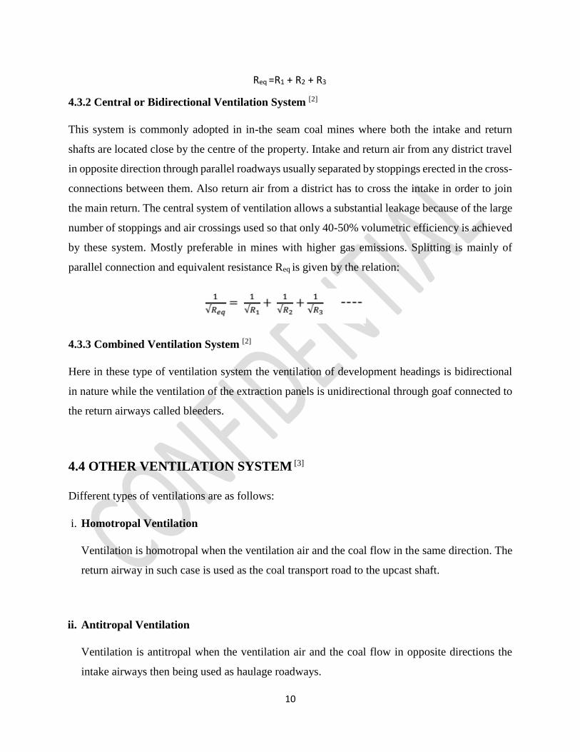
4.3.2 Central or Bidirectional Ventilation System [2]
This system is commonly adopted in in-the seam coal mines where both the intake and return
shafts are located close by the centre of the property. Intake and return air from any district travel
in opposite direction through parallel roadways usually separated by stoppings erected in the cross-
connections between them. Also return air from a district has to cross the intake in order to join
the main return. The central system of ventilation allows a substantial leakage because of the large
number of stoppings and air crossings used so that only 40-50% volumetric efficiency is achieved
by these system. Mostly preferable in mines with higher gas emissions. Splitting is mainly of
parallel connection and equivalent resistance Req is given by the relation:
4.3.3 Combined Ventilation System [2]
Here in these type of ventilation system the ventilation of development headings is bidirectional
in nature while the ventilation of the extraction panels is unidirectional through goaf connected to
the return airways called bleeders.
4.4 OTHER VENTILATION SYSTEM [3]
Different types of ventilations are as follows:
i. Homotropal Ventilation
Ventilation is homotropal when the ventilation air and the coal flow in the same direction. The
return airway in such case is used as the coal transport road to the upcast shaft.
ii. Antitropal Ventilation
Ventilation is antitropal when the ventilation air and the coal flow in opposite directions the
intake airways then being used as haulage roadways.
Req =R1 + R2 + R3
11
iii. Ascensional Ventilation
It implies taking the intake ventilating air to the lowest point of a district or face and allow it to
travel to higher levels to ventilate the district or face before it goes to return.
iv. Descensional Ventilation
In this system, the air travels downhill from the rise side of a district to the lower levels along
the working places and return being at the bottom end of the working place.
v. Exhausting System
With the exhaust system, the quantity of air available at the face may be sufficient, but unless
the duct or tubing is maintained close to the face the velocity may be inadequate to sweep the
air across the face. Dust concentration is greatly reduced. Dust and gases are drawn into the
duct and discharge into the return air course.
vi. Blowing or forcing system
With a blowing system intake air at high velocity can be directed against the face through a
duct. It therefore cannot pick up moisture or dust on its journey to the face and it arrives in a
clean dry condition. The method is therefore particularly suitable for wet headings where the
rock temperature is high.
vii. Combined Exhaust and Blower system
Using a blower in conjunction with exhaust system provide the advantage of both systems. The
system is most suitable for continuous miner faces. The principal advantage of this system is
that both the fans be operating to be truly effective.
12
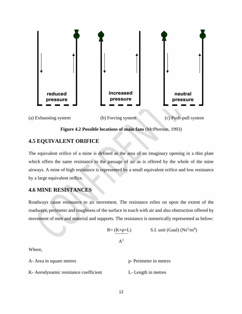
(a) Exhausting system (b) Forcing system (c) Push-pull system
Figure 4.2 Possible locations of main fans (McPherson, 1993)
4.5 EQUIVALENT ORIFICE
The equivalent orifice of a mine is defined as the area of an imaginary opening in a thin plate
which offers the same resistance to the passage of air as is offered by the whole of the mine
airways. A mine of high resistance is represented by a small equivalent orifice and low resistance
by a large equivalent orifice.
4.6 MINE RESISTANCES
Roadways cause resistance to air movement. The resistance relies on upon the extent of the
roadways, perimeter and roughness of the surface in touch with air and also obstruction offered by
movement of men and material and supports. The resistance is numerically represented as below:
R= (K×p×L) S.I. unit (Gaul) (Ns2/m8)
A3
Where,
A- Area in square metres
K- Aerodynamic resistance coefficient
p- Perimeter in metres
L- Length in metres
13
N in Newton, s in seconds, m in metres S.I-Standard International
4.6.1 Laws of Mine Air Friction
The laws which govern the passage of air in the mine are as follows:
Law I : P α S where, S= rubbing surface
= perimeter of airway × length
Law II: P α V2 where, V= air velocity
Law III: P α 1/A where, A= area of cross section
Law IV: P α K where, K= co-efficient of friction
Conditions in which obstructions and disturbances are minimum should be ideally selected for
measurement to get a realistic pressure and quantity summary of the mine. Hence it is wise to
conduct ventilation surveys while there is no activity taking place likely during on a non-working
shift. Mine resistance is often affected by the following reasons:
• Movement of tubs, vehicles etc.
• Falling water in upcast shafts.
• During opening of mine doors.
• Leakage through overcasts or air crossings.
• Movement of personnel’s and workers.
• Unexpected environmental changes.
4.7 MINE SYSTEM AND CONTROL DEVICES [2]
A well designed and properly implemented ventilation system will provide beneficial
physiological and psychological side effects that enhance employee safety, comfort, health, and
morale. In planning a ventilation system, the quantity of air it will be necessary to circulate to meet
all health and safety standards must be decided at the outset. Once the quantity required has been
fixed, the correct size of shafts, number of airways, and fans can be determined. As fresh air enters
the system through the intake airshaft(s) or other connections to the surface, it flows along intake
airways to the working areas where the majority of pollutants are added to the air. These include
14
dust and a combination of many other potential hazards, such as toxic or flammable gases, heat,
humidity, and radiation. The contaminated air passes back through the system along return
airways. In most cases, the concentration of contaminants is not allowed to exceed mandatory
threshold limits imposed by law. The return (or contaminated, exhausted) air eventually passes
back to the surface via return airshaft(s), or through inclined or level drifts. Air always flows along
the path of least resistance, but this may not be where it is required for use. To direct the air where
it is needed, ventilation devices are necessary; the primary means of producing and controlling the
airflow for the entire system are mine fans (either in the form of single fan installation or multiple
fans). In addition, many other control devices also are necessary for effective underground air
distribution:
4.7.1 Splitting
In a mine which is having multiple working districts it is always desirable to split the air flow to
the sections/districts of the mine where the demand of air quantity arises and requires a separate
route for flow. Like the combination of airways in parallel, which reduces their resistance, splits
reduce the overall resistance of the mine and increase the air quantity .To control the flow of air to
different working districts , the resistance of the split can be varied.
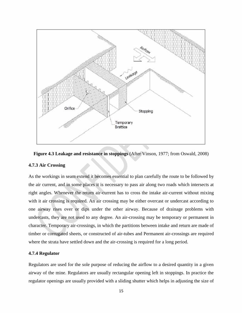
4.7.2 Stoppings
Stoppings are used to block off an old roadway which is no more required for haulage, travelling
or ventilation purpose and to create any close connection between the main intake and main return.
Every ventilation stopping between the main intake and main return airways in coal mines is made
up of either brickwork or masonry of a minimum thickness of 38 cm and suitably plastered by lime
or cement mortar to prevent leakage of air. Explosion proof stopping preferable for degree 2 and
3 mines should be atleast 1.5 m thick brick wall. Important fireproof and explosion proof stoppings
in coal mines should be made of two thick brick or concrete walls, spaced out a certain distance
depending on the strength desired, and the intervening space filled with broken rock, sand and
clay, etc.
15
Figure 4.3 Leakage and resistance in stoppings (After Vinson, 1977; from Oswald, 2008)
4.7.3 Air Crossing
As the workings in seam extend it becomes essential to plan carefully the route to be followed by
the air current, and in some places it is necessary to pass air along two roads which intersects at
right angles. Whenever the return air-current has to cross the intake air-current without mixing
with it air crossing is required. An air crossing may be either overcast or undercast according to
one airway rises over or dips under the other airway. Because of drainage problems with
undercasts, they are not used to any degree. An air-crossing may be temporary or permanent in
character. Temporary air-crossings, in which the partitions between intake and return are made of
timber or corrugated sheets, or constructed of air-tubes and Permanent air-crossings are required
where the strata have settled down and the air-crossing is required for a long period.
4.7.4 Regulator
Regulators are used for the sole purpose of reducing the airflow to a desired quantity in a given
airway of the mine. Regulators are usually rectangular opening left in stoppings. In practice the
regulator openings are usually provided with a sliding shutter which helps in adjusting the size of
16
the opening to suit the requirements. Regulators can be permanent when they are constructed of
steel in a concrete stopping, but more often they are temporary in nature, when they are in the form
of an open wooden frame in a stopping made up of brattice cloth nailed on to a wooden frame
work. The air quantity can be adjusted by varying the size of the opening by nailing on strips of
wood on the side of the opening.
4.7.5 Doors
When access through stoppings become essential then doors are used. Doors should be preferably
open on one side, i.e. the high pressure side, opening in the other direction being checked by the
frame. Normally, two doors used forming an air-lock so that one is always closed when the other
is open. These doors are used as main separation doors near the shafts, whilst one door may suffice
near the face.
The door frames are set in suitable air tight stoppings, made of cement concrete and the doors hung
from them either vertically or horizontally by means of two or three strap iron hinges. Doors and
door-frames must be strong and fireproof in construction. Steel doors for the purpose should have
a minimum thickness of 3 mm.
4.7.5 Air locks
An airlock is a set of two doors so installed that one of them is always shut when the other is
opened to pass men, tubs or a train. This not only minimizes leakage but becomes essential where
the ventilation system is likely to be disturbed seriously by too frequent or prolonged opening of
the doors. Indian coal mines regulations require that airlocks should be provided between main
intakes and returns. Airlocks should also be provided where the pressure across the door is high.
4.7.6 Brattice Cloth
This is simply a sheet or sheets of canvas hung from props and planks to prevent the short circuit
of air from intake to return, so causing the ventilation air to reach the faces. It may be used as a
screen across an airway to prevent or reduce the flow of air along it, or as a partition along a
roadway to divide it into two parts, intake and return or as hard screen to divert an air current
upwards into a roof cavity to clear away any accumulation of gas. Brattice cloth coated with P.V.C
17
is impermeable to airflow, and more suitable for line brattice to ventilate a heading. Brattices
should be of fire resistant type.
4.7.7 Booster fans
Booster fans are used sometimes for augmenting ventilation in certain districts. They increase
quantity by increasing the pressure causing flow. It is used when the desired increase of the airflow
cannot be achieved economically. But it is essential to have a judicious choice of the size of a
booster fan because too large a booster in one split can cause stoppage of air current or even
reversal of the air current in the other splits.
18
CHAPTER 5
METHODOLOGY
5.1 AIR QUANTITY SURVEYS [3]
The quantity of air passing through any airway every second, Q is generally given by the
expression
Where, U = Velocity of air passing through that point (m/s)
A = Area of roadway (m2)
Thus to calculate the quantity of air flowing past any particular measuring station, it is necessary-
a) To ascertain the cross sectional area of the passage =A sq. metres.
b) To measure the velocity of air current= V metres per second.
5.2 PRESSURE SURVEYS [3]
The basic principle behind the pressure surveying in a mine is Bernoulli’s Theorem which states
that, assuming no friction losses, the total pressure or energy of the moving stream of air remains
constant throughout a passage of varying cross-section. Let P, is the pressure of air raised by a
compressing fan to a total pressure corresponding to a motive column is P. this total pressure is
made up of two components- the static pressure of the air (PS) and its velocity pressure (PV).The
static pressure may itself be regarded as partly the normal atmospheric pressure (static) =H, and
partly the static pressure above atmospheric= PS.
Hence, for a compressing fan, P= H + PV + PS
And the fan pressure (compression), p= PV + PS
In an exhausting fan, a depression is created in the fan drift, and the term PS become negative.
Hence, for an exhausting fan, P= H + PV - PS
And the fan pressure (depression), p= PS - PV
Q= U x A (m3/s)
19
Air always flows from a region of higher pressure to lower pressure and, when a mine is ventilated
by the surface fan, the maximum pressure is found at the top of the downcast shaft and the
minimum pressure in the fan drift at the top of the upcast shaft. The difference (relatively small)
between these two pressures represents the pressure causing flow of the air, i.e. the ventilation
pressure or water gauge. When the air traverses the mine airways, often kilometers in length, there
is a gradual fall of pressure, or pressure drop, from point to point.
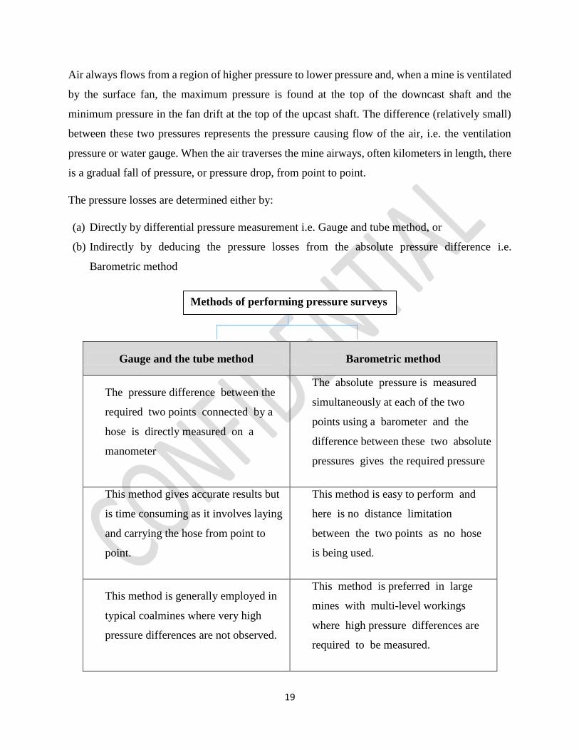
The pressure losses are determined either by:
(a) Directly by differential pressure measurement i.e. Gauge and tube method, or
(b) Indirectly by deducing the pressure losses from the absolute pressure difference i.e.
Barometric method
Gauge and the tube method Barometric method
The pressure difference between the
required two points connected by a
hose is directly measured on a
manometer
The absolute pressure is measured
simultaneously at each of the two
points using a barometer and the
difference between these two absolute
pressures gives the required pressure
This method gives accurate results but
is time consuming as it involves laying
and carrying the hose from point to
point.
This method is easy to perform and
here is no distance limitation
between the two points as no hose
is being used.
This method is generally employed in
typical coalmines where very high
pressure differences are not observed.
This method is preferred in large
mines with multi-level workings
where high pressure differences are
required to be measured.
Methods of performing pressure surveys
20
The choice of instrument for pressure survey depends on the extent of mine workings, the accuracy
required, portability of the instrument and time available to carry out the survey. In most Indian
mines, the ventilation pressure is very small. It rarely exceeds 25mm to 50 mm of water gauge and
in the traverse of the circuit the pressure drop for a short section of airway is small. Pressure survey
is made by the various types of pressure measuring instrument including:
1. Sensitive manometers: The sensitive manometers are mostly used for the measurement of
fan pressure, for determining the pressure difference across separation doors between intake
and return, at the pit bottom and at several other places in the mine [3].
2. Pressure survey meters: It is a sensible type velometer calibrated to read pressure difference
in mm of water-gauge. The pressure survey meters are most suitable for carrying out detail
survey of a small mine or part of an extensive mine. Only trained persons can take the readings
under strenuous conditions during its use [3].
3. Sensitive aneroid barometers: A barometer must be placed above ground near the entrance
to the mine and must be read and recorded every day. A record of barometric pressure
variations at the pit top at regular intervals of 15 minutes is needed to be maintained during
ventilation measurements [3].
4. Graham’s pressure survey apparatus: The graham’s pressure survey apparatus is used in
the same way as barometers. But as the pressure measuring element is a gas and not a metal,
it voids creep and time lag associated with barometers [3].
5.3 EQUIPMENTS REQUIRED FOR A PRESSURE-QUANTITY SURVEY
1 Rotating vane anemometer
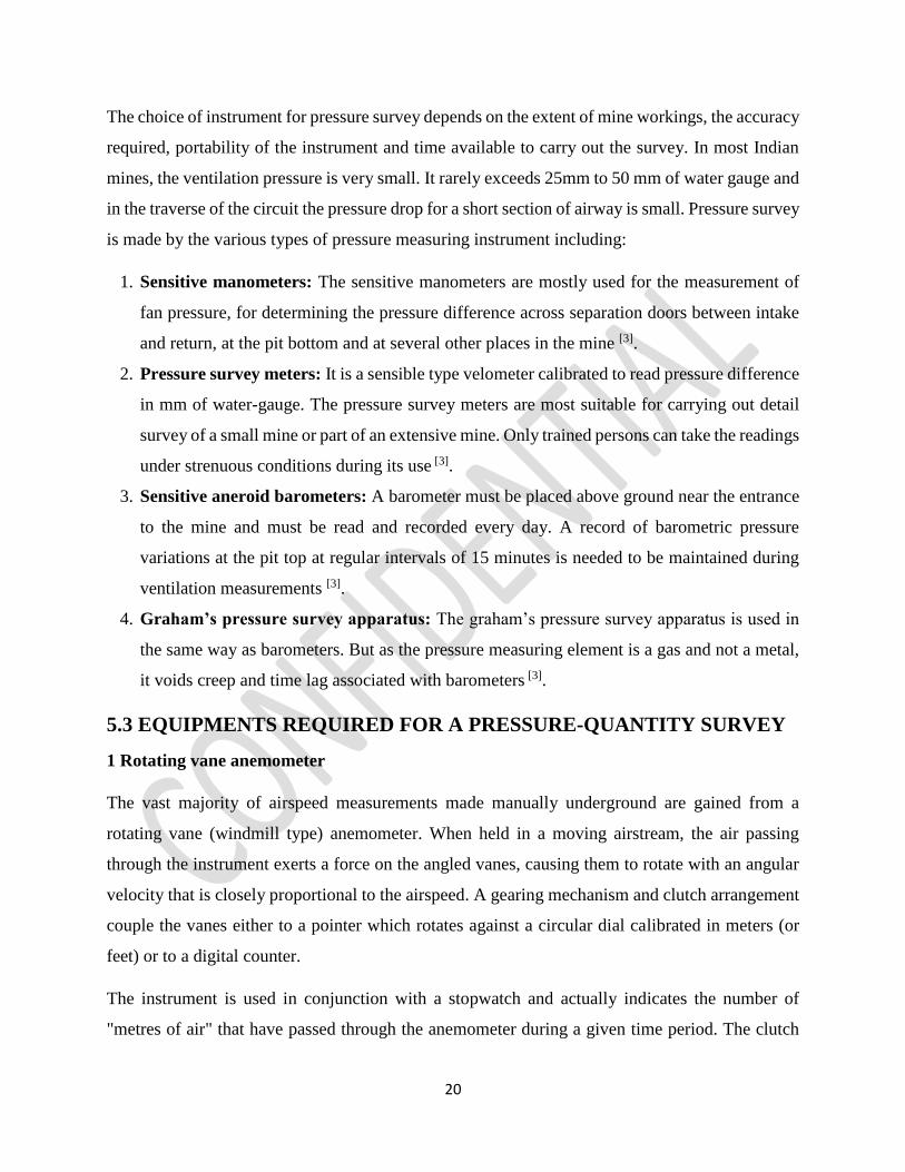
The vast majority of airspeed measurements made manually underground are gained from a
rotating vane (windmill type) anemometer. When held in a moving airstream, the air passing
through the instrument exerts a force on the angled vanes, causing them to rotate with an angular
velocity that is closely proportional to the airspeed. A gearing mechanism and clutch arrangement
couple the vanes either to a pointer which rotates against a circular dial calibrated in meters (or
feet) or to a digital counter.
The instrument is used in conjunction with a stopwatch and actually indicates the number of
"metres of air" that have passed through the anemometer during a given time period. The clutch
21
device is employed to stop and start the pointer or digital counter while the vanes continue to
rotate. A zero reset lever is also incorporated into the instrument. Low range vane anemometers
will typically have eight vanes, jewelled bearings and give repeatable readings for velocities in the
range 0.25 to 15 m/s. High range instruments may have four vanes, low-friction roller or ball
bearings and can be capable of measuring air velocities as high as 50 m/s. Digital vane
anemometers indicate directly on an odometer counter, an illuminated screen, or feed an electronic
signal into a data gathering system. Modern handheld instruments may also be fitted with a
microprocessor to memorize readings, dampen out rapid variations in velocity or into which can
be entered the cross-sectional area for the calculation of volume flow.
Figure 5.1 Instrument’s needed to conduct a ventilation survey [1]
Plate 5.1 Dial-vane anemometer Figure 5.2 Components of a Dial vane
Anemometer [22]
22
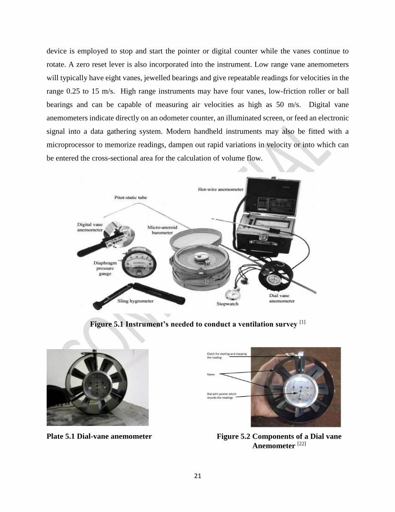
2 Inclined Tube Manometer
A variable inclination inclined tube manometer fabricated by DGMS for the purpose of the study
at Nandira is used for the differential pressure survey. The inclination of the tube could be set at
1:2, 1:5, and 1:10 depending on the amount of the pressure difference to be measured. The
manometer has provision for accurate levelling with the help of three levelling screws when placed
on a hard and even surface.
Plate 5.2 Inclined-tube manometer
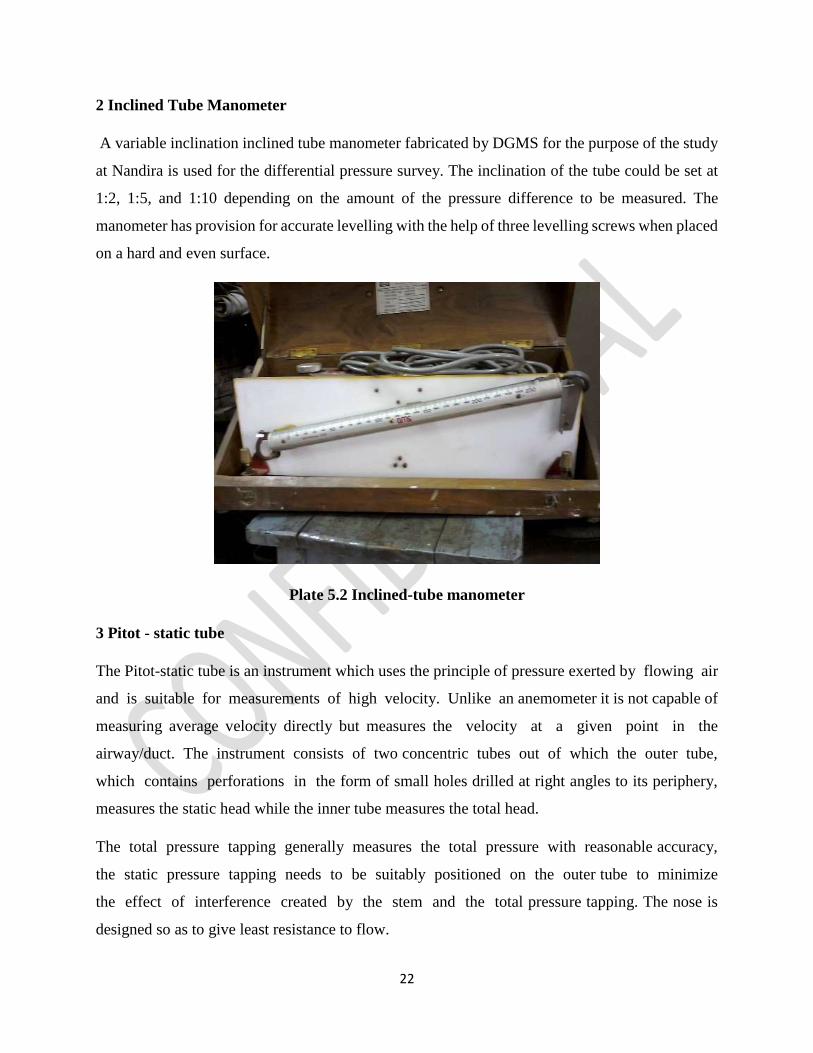
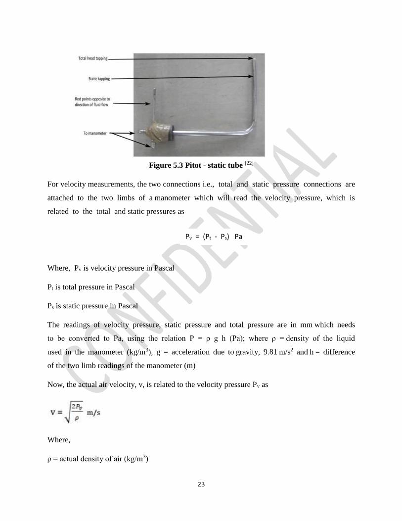
3 Pitot - static tube
The Pitot-static tube is an instrument which uses the principle of pressure exerted by flowing air
and is suitable for measurements of high velocity. Unlike an anemometer it is not capable of
measuring average velocity directly but measures the velocity at a given point in the
airway/duct. The instrument consists of two concentric tubes out of which the outer tube,
which contains perforations in the form of small holes drilled at right angles to its periphery,
measures the static head while the inner tube measures the total head.
The total pressure tapping generally measures the total pressure with reasonable accuracy,
the static pressure tapping needs to be suitably positioned on the outer tube to minimize
the effect of interference created by the stem and the total pressure tapping. The nose is
designed so as to give least resistance to flow.
23
Figure 5.3 Pitot - static tube [22]
For velocity measurements, the two connections i.e., total and static pressure connections are
attached to the two limbs of a manometer which will read the velocity pressure, which is
related to the total and static pressures as
Where, Pv is velocity pressure in Pascal
Pt is total pressure in Pascal
Ps is static pressure in Pascal
The readings of velocity pressure, static pressure and total pressure are in mm which needs
to be converted to Pa, using the relation P = ρ g h (Pa); where ρ = density of the liquid
used in the manometer (kg/m3), g = acceleration due to gravity, 9.81 m/s2 and h = difference
of the two limb readings of the manometer (m)
Now, the actual air velocity, v, is related to the velocity pressure Pv as
Where,
ρ = actual density of air (kg/m3)
Pv = (Pt - Ps) Pa
24
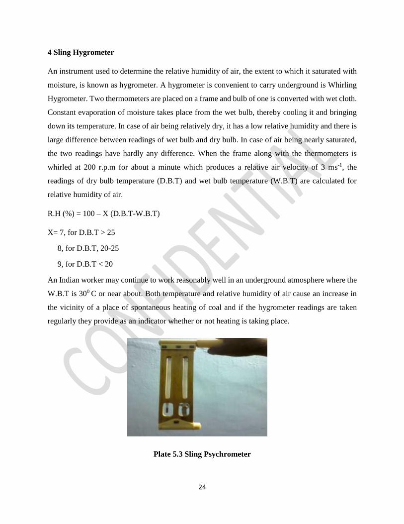
4 Sling Hygrometer
An instrument used to determine the relative humidity of air, the extent to which it saturated with
moisture, is known as hygrometer. A hygrometer is convenient to carry underground is Whirling
Hygrometer. Two thermometers are placed on a frame and bulb of one is converted with wet cloth.
Constant evaporation of moisture takes place from the wet bulb, thereby cooling it and bringing
down its temperature. In case of air being relatively dry, it has a low relative humidity and there is
large difference between readings of wet bulb and dry bulb. In case of air being nearly saturated,
the two readings have hardly any difference. When the frame along with the thermometers is
whirled at 200 r.p.m for about a minute which produces a relative air velocity of 3 ms-1, the
readings of dry bulb temperature (D.B.T) and wet bulb temperature (W.B.T) are calculated for
relative humidity of air.
R.H (%) = 100 – X (D.B.T-W.B.T)
X= 7, for D.B.T > 25
8, for D.B.T, 20-25
9, for D.B.T < 20
An Indian worker may continue to work reasonably well in an underground atmosphere where the
W.B.T is 300 C or near about. Both temperature and relative humidity of air cause an increase in
the vicinity of a place of spontaneous heating of coal and if the hygrometer readings are taken
regularly they provide as an indicator whether or not heating is taking place.
Plate 5.3 Sling Psychrometer
25
5 Nylon Tubes
For measuring the static pressure differential between two station, nylon tubes of 8mm diameter
and thickness of 4mm of length 20m was connected with Pitot tube at either end via connectors to
prevent leakage.
6 Stop Watch
For the purpose of recording time during air quantity survey for a duration of one minute a stop
watch was an essential equipment.
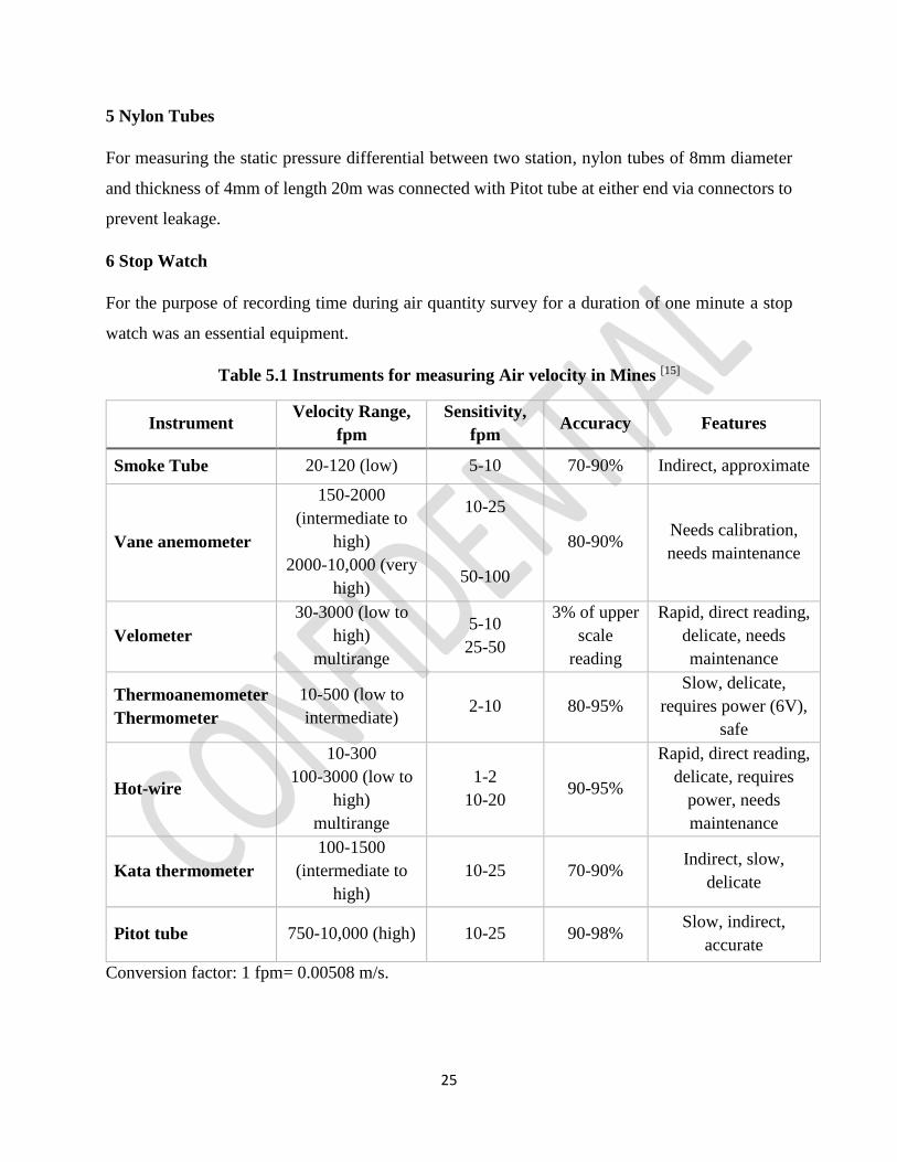
Table 5.1 Instruments for measuring Air velocity in Mines [15]
Instrument Velocity Range,
fpm
Sensitivity,
fpm Accuracy Features
Smoke Tube 20-120 (low) 5-10 70-90% Indirect, approximate
Vane anemometer
150-2000
(intermediate to
high)
2000-10,000 (very
high)
10-25
50-100
80-90% Needs calibration,
needs maintenance
Velometer
30-3000 (low to
high)
multirange
5-10
25-50
3% of upper
scale
reading
Rapid, direct reading,
delicate, needs
maintenance
Thermoanemometer
Thermometer
10-500 (low to
intermediate) 2-10 80-95%
Slow, delicate,
requires power (6V),
safe
Hot-wire
10-300
100-3000 (low to
high)
multirange
1-2
10-20 90-95%
Rapid, direct reading,
delicate, requires
power, needs
maintenance
Kata thermometer
100-1500
(intermediate to
high)
10-25 70-90% Indirect, slow,
delicate
Pitot tube 750-10,000 (high) 10-25 90-98% Slow, indirect,
accurate
Conversion factor: 1 fpm= 0.00508 m/s.
26
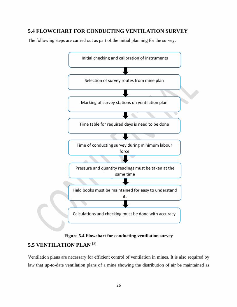
5.4 FLOWCHART FOR CONDUCTING VENTILATION SURVEY
The following steps are carried out as part of the initial planning for the survey:
Figure 5.4 Flowchart for conducting ventilation survey
5.5 VENTILATION PLAN [2]
Ventilation plans are necessary for efficient control of ventilation in mines. It is also required by
law that up-to-date ventilation plans of a mine showing the distribution of air be maintained as
Initial checking and calibration of instruments
Selection of survey routes from mine plan
Marking of survey stations on ventilation plan
Time table for required days is need to be done
Time of conducting survey during minimum labour
force
Pressure and quantity readings must be taken at the
same time
Field books must be maintained for easy to understand
it.
Calculations and checking must be done with accuracy
27
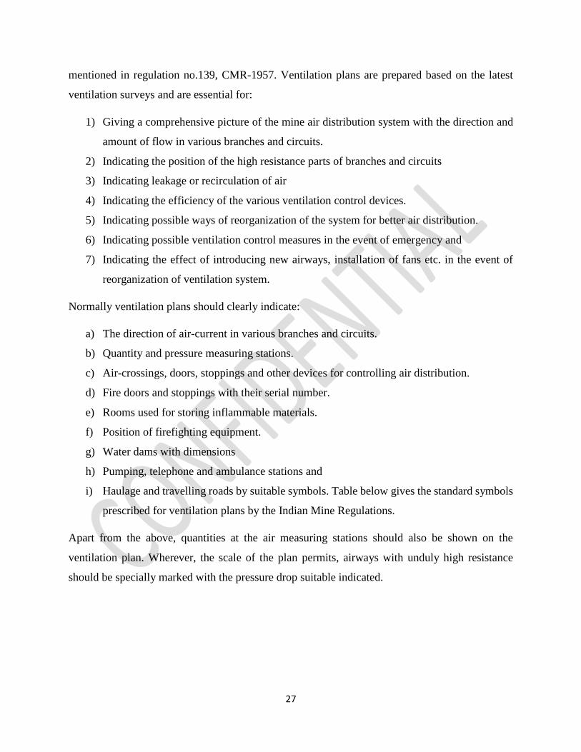
mentioned in regulation no.139, CMR-1957. Ventilation plans are prepared based on the latest
ventilation surveys and are essential for:
1) Giving a comprehensive picture of the mine air distribution system with the direction and
amount of flow in various branches and circuits.
2) Indicating the position of the high resistance parts of branches and circuits
3) Indicating leakage or recirculation of air
4) Indicating the efficiency of the various ventilation control devices.
5) Indicating possible ways of reorganization of the system for better air distribution.
6) Indicating possible ventilation control measures in the event of emergency and
7) Indicating the effect of introducing new airways, installation of fans etc. in the event of
reorganization of ventilation system.
Normally ventilation plans should clearly indicate:
a) The direction of air-current in various branches and circuits.
b) Quantity and pressure measuring stations.
c) Air-crossings, doors, stoppings and other devices for controlling air distribution.
d) Fire doors and stoppings with their serial number.
e) Rooms used for storing inflammable materials.
f) Position of firefighting equipment.
g) Water dams with dimensions
h) Pumping, telephone and ambulance stations and
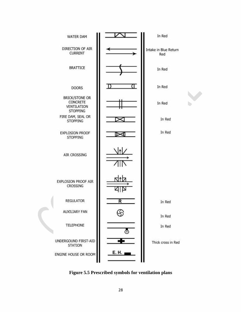
i) Haulage and travelling roads by suitable symbols. Table below gives the standard symbols
prescribed for ventilation plans by the Indian Mine Regulations.
Apart from the above, quantities at the air measuring stations should also be shown on the
ventilation plan. Wherever, the scale of the plan permits, airways with unduly high resistance
should be specially marked with the pressure drop suitable indicated.
28
Figure 5.5 Prescribed symbols for ventilation plans
29
5.6 SELECTION OF MEASUREMENT STATION for PRESSURE
QUANTITY SURVEY [22]
Measurement stations are generally fixed permanently after extensive reconnaissance to
ensure as much accuracy as possible. The following criteria should be kept in mind while
selecting a measurement station-
It should preferably be in a straight roadway
The associated roadway should have a regular cross section throughout its length to
help maintain accuracy in area calculations
No obstructions should be present near the measurement station
The station should not be situated near junctions or bends in the roadway
5.7 PROCEDURE FOR CONDUCTING PRESSURE SURVEY BY GAUGE-
TUBE [3]
The procedure for conducting a gauge and tube survey is as follows:
(a) The survey is commenced from the intake air path to return path and moved in the direction
of air current.
(b) The inclined manometer is clamped to a tripod stand and levelling was done.
(c) A short connection between the gauge limb and the hose pipe was made by a short rubber
tubing. A similar length of light tubing is attached to the open end of the hose pipe and to the
other limb of the gauge
(d) The inclined gauge was placed between adjacent stations and the flexible hose was run to
extend from station to station.
(e) The ends of the hose are held so that they both face the air current and thus automatically take
account of the total pressure, including both the static and the velocity components.
(f) All readings are carefully noted.
(g) The instruments and tubes are then taken forward and the procedure is repeated in all the
stations.
30
5.8 MEASUREMENT OF CROSS-SECTIONAL AREA
The accuracy of calculation of air quantity is equally influenced by the accuracy of
measurement of air velocity and accuracy in measurement of the cross sectional area of
the roadway. Thus it is of utmost importance to ensure that a systematic method is used to
carry out area measurements. Normally, one of the following methods is used for the cross-
sectional area measurements:
Taping
Offset method
Profilometer method
Craven sunflower method
Photographic method
5.8.1 Taping [2]
This is the simplest and the most common method of cross sectional area calculation in
mines. In this method, a tape is stretched across the airway and with help of another tape
perpendicular offsets to the periphery of the airway on either side of the stretched tape are taken
at regular intervals of 0.3-0.5 m. The measurements can be plotted to a certain scale and the area
of the resulting diagram determined by a plan meter.
5.8.2 Offset Method [14]
In this method, tapes or strings are stretched across the airway to give a rectangular shape. With
the help of another tape perpendicular to the periphery of the airway are taken at frequent intervals
of say 0.3 to 0.5 m. the measurements can be plotted on a graph paper from which the cross-
sectional area is determined.
5.8.3 Profilometer Method [2]
This method consists essentially of the equipment used in the plane table method except for the
incorporation of a mechanical scaling device similar to that in a pantograph so that the profile of
the airway is automatically plotted on the paper mounted on the plane table. This makes the
instrument quicker and obviates any personal error in the plotting of the rays.
31
5.8.4 Craven Sunflower Method [2]
The method utilizes a graduated brass rod which is adjustable in length and can be rotated about a
central point in the airway through a full circle. Measurements from a central point in the airway
to the periphery are taken at various angles, the rod being adjusted every time so as to read the
lengths at these angles. The measurements can be plotted to scale and the area computed thereform.
5.8.5 Photographic Method [14]
In this method, the periphery of the measuring station is marked with a white paint and
photographed along with a measuring scale placed in the plane of the cross-section. Very often the
whole cross section of the airway is not available for airflow with obstructions created by
conveyors, ventilation ducts, pipes, spillage of coal and other equipment. The cross-sectional area
of the obstructions should be determined and subtracted from the overall roadway area.
5.9 TRAVERSING METHODS
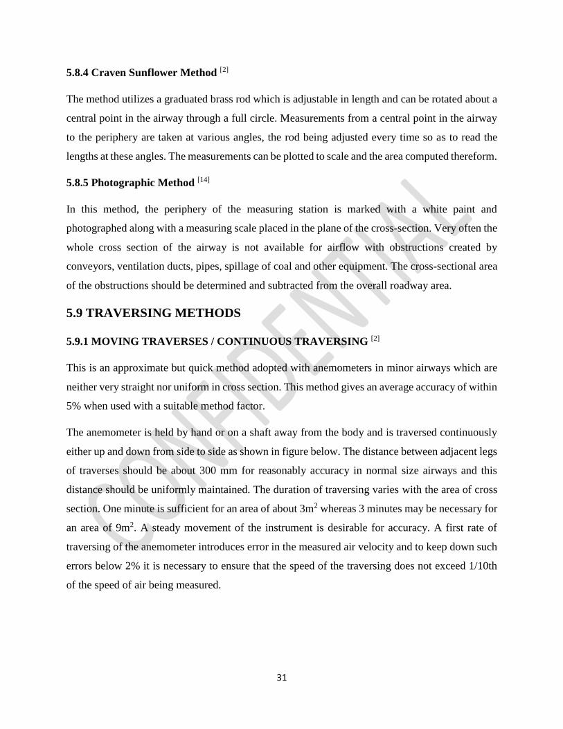
5.9.1 MOVING TRAVERSES / CONTINUOUS TRAVERSING [2]
This is an approximate but quick method adopted with anemometers in minor airways which are
neither very straight nor uniform in cross section. This method gives an average accuracy of within
5% when used with a suitable method factor.
The anemometer is held by hand or on a shaft away from the body and is traversed continuously
either up and down from side to side as shown in figure below. The distance between adjacent legs
of traverses should be about 300 mm for reasonably accuracy in normal size airways and this
distance should be uniformly maintained. The duration of traversing varies with the area of cross
section. One minute is sufficient for an area of about 3m2 whereas 3 minutes may be necessary for
an area of 9m2. A steady movement of the instrument is desirable for accuracy. A first rate of
traversing of the anemometer introduces error in the measured air velocity and to keep down such
errors below 2% it is necessary to ensure that the speed of the traversing does not exceed 1/10th
of the speed of air being measured.
32
Figure 5.6 Path of a moving anemometer traverse [1]
5.9.2 FIXED POINT TRAVERSES /SINGLE POINT MEASUREMENT [2]
In this method, the measuring instrument (anemometer, velometer or pitot static tube) is held in a
fixed point on the cross section of the airway and the reading multiplied by a method factor to get
the average velocity. The instrument has to be held well away from the body of the observer. That
is why anemometers should preferably be mounted on shafts. Usually readings at the centre are
taken and these are multiplied by a method factor of 0.8 for getting the average values of velocity.
The method factor varies with the roughness of the sides of the airway and the Reynolds number.
However, it can be taken to be constant for turbulent flow with high Reynolds numbers (>50000)
as in the case of mine air currents commonly measured with anemometers or pitot static tubes. The
method factor is unity at one-seventh of the distance between opposite walls from any wall, or in
other words, the average velocity can be obtained directly by placing the instruments at this point.
An accuracy of 5 % can be obtained with single point measurement by an anemometer if the airway
is straight and of uniform cross section.
5.9.3 METHOD OF EQUAL AREAS / PRECISE TRAVERSING [2]
This is a very highly accurate method of measuring air velocity by anemometers, velometers or
pitot static tubes. An accuracy of 2% can be obtained with this method of traversing by
anemometers. However, this method is more time-consuming and hence should be confined to
measurements in major airways only where a great deal of accuracy is needed.
Precise traversing should be done in straight portions of airways of uniform cross-section and
preferably in smooth-lined portions away from any obstructions. The observer should stand at least
33
1.2m away from the instrument on the downstream ide and the instrument should be mounted on
a shaft. It is better if the observer stands in a suitable recess on the downstream side of the airway.
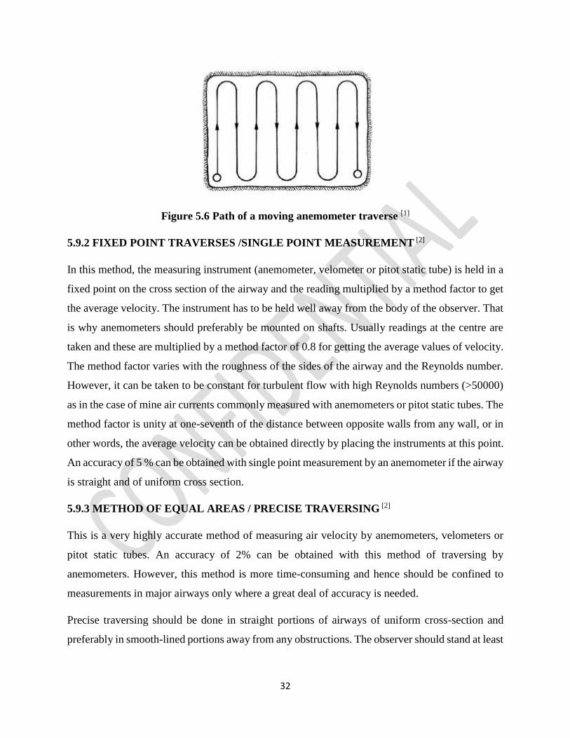
(a) RECTANGULAR[2]
Figure 5.7 Measuring points for a fixed point traverse in a rectangular opening [1]
In this method, the cross section of the airway is divided into equal areas of 300 mm square for
ordinary mine airways, the size being less for airways of lesser cross-sectional area as in the case
of ducts. Wires are stretched across the airway in such a way that points of their intersection
coincides with the centres of these areas where observation has to be made. The instrument is then
held at each of these observation points for a suitable length of time, say, a minute or so and the
velocity is recorded. The average velocity can then be calculated from these velocities. As a guide,
the recommended number of points, n, for a rectangular opening may be estimated as:
Where; e is the exponential exponent, 2.7183 and
A is the cross-sectional area (m)
The estimated number of points may then be rounded to a value that is convenient for subdividing
the cross-sectional area but should never be less than 24. Correct positioning of the measuring
instrument is facilitated by erecting a grid of fine wires in the airway to represent the subsections.
n=100 e-8/A+23
34
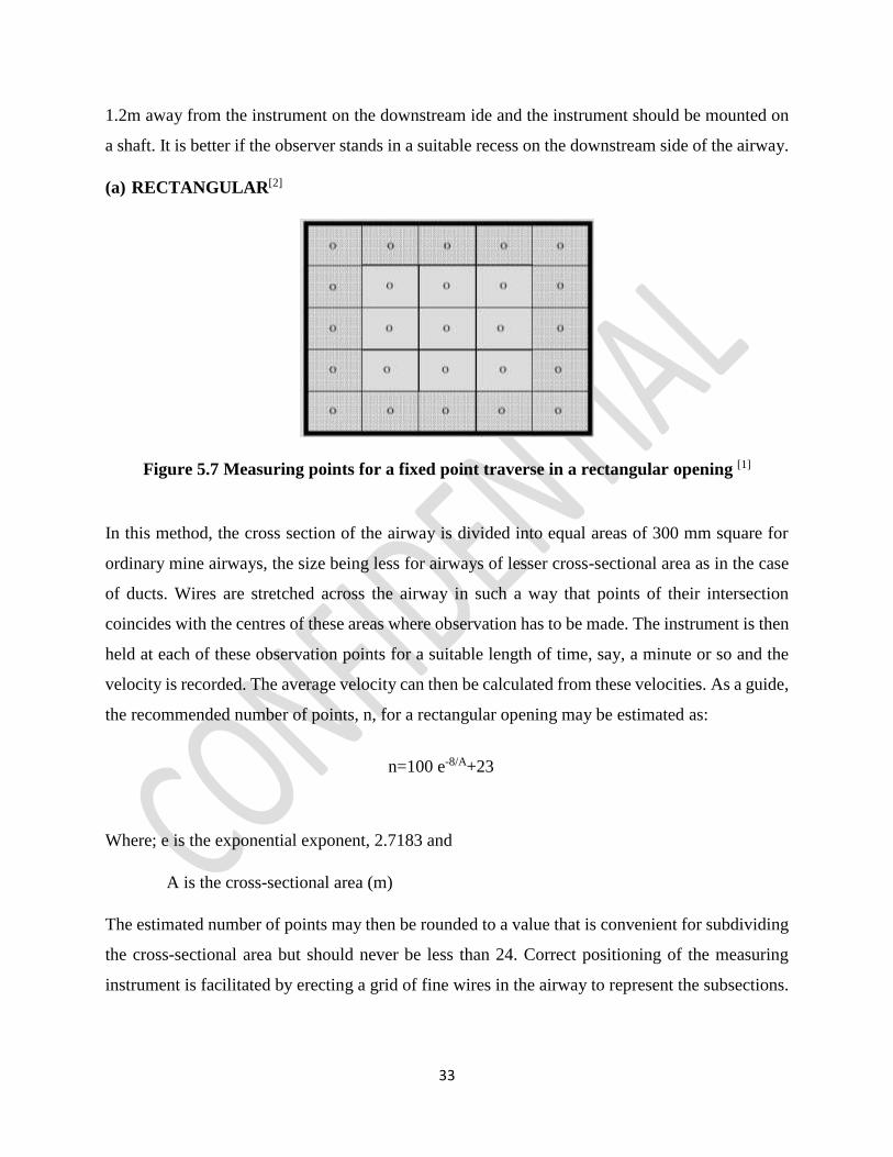
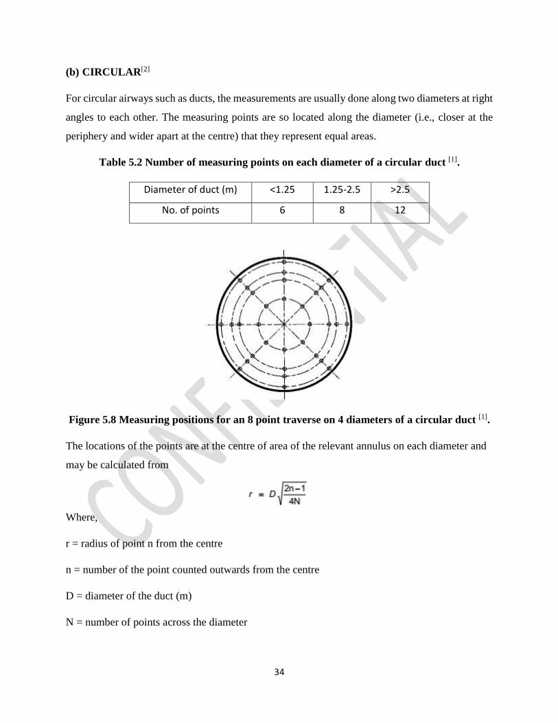
(b) CIRCULAR[2]
For circular airways such as ducts, the measurements are usually done along two diameters at right
angles to each other. The measuring points are so located along the diameter (i.e., closer at the
periphery and wider apart at the centre) that they represent equal areas.
Table 5.2 Number of measuring points on each diameter of a circular duct [1].
Diameter of duct (m) <1.25 1.25-2.5 >2.5
No. of points 6 8 12
Figure 5.8 Measuring positions for an 8 point traverse on 4 diameters of a circular duct [1].
The locations of the points are at the centre of area of the relevant annulus on each diameter and
may be calculated from
Where,
r = radius of point n from the centre
n = number of the point counted outwards from the centre
D = diameter of the duct (m)
N = number of points across the diameter
35
5.10 SURVEY RECORDS [2]
Results of ventilation surveys should be suitably recorded and so tabulated as to reveal at a glance
the changes in air quantity and pressure. It is also desirable to get the survey results plotted on a
ventilation plan of a suitable scale, which should show the air quantities at the various survey
stations. An idea of the variation in the resistance of the airways can be obtained by plotting the
pressure drop along an airway against the distance. A good way of representing the pressure survey
on the ventilation plan is to mark out sections of airways over which a fixed drop of pressure takes
place. A short section indicates a high resistance whereas a long one indicates a low resistance.
Ventilation measurement data should be recorded at the survey station for ready reference.
In India it is required to post a check board at all air measuring stations in the return in gassy coal
mines showing:
a) The serial number of the station.
b) The quantity required to pass through the airway.
c) The cross-sectional area of the airway at the section.
d) The last date of air measurement.
e) Measured air velocity.
f) Measured air quantity.
g) Percentage of inflammable gas in the general body of air and
h) The signature of the ventilation officer with date.
5.11 HYGROMETRIC SURVEYS
Hygrometric survey in mines is normally carried out to check and control the environmental
conditions at various parts of the mine so as to maintain the mine atmosphere (wet-bulb
temperature and air velocity) within statutorily permissible limits. It is generally carried out by
whirling hygrometers, the survey proceeding in a regular manner from the top of the downcast
shaft to that of the upcast shaft. Readings must be taken at all splits, points of leakages, haulages,
compressors etc., psychrometric readings should be accompanied by measurements of pressure
and quantity of air flowing.
36
Mine air always contains some amount of moisture. There is a maximum quantity of moisture
which can be contained in any space of gas, air or even vacuum at a certain temperature. When the
air at a particular temperature contains the maximum amount of water vapour it can hold, it is
called saturated and can pick up no more water vapour at that temperature. On the other hand if
the air can still pick up some more water vapour at the prevailing temperature, it is called
unsaturated [2].
5.11.1 Saturated Vapour Pressure [14]
This is the maximum pressure that can be exerted by the water vapour in a saturated atmosphere
corresponding to a particular temperature and is expressed in kPa.
5.11.2 Vapour Pressure [2]
This is the partial pressure of water vapour present in a certain volume of air expressed in kPa.
This is also sometimes called actual vapour pressure.
5.11.3 Relative Humidity [2]
It is used to represent the moisture content of air. This is the ratio of actual vapour pressure to the
saturation vapour pressure at the temperature of observation expressed as a percentage.
5.11.4 Dry Bulb Temperature
Dry Bulb Temperature refers to the ambient air temperature since the temperature indicated in the
thermometer is free from any moisture in air. It is also ordinarily referred to be the temperature of
air as it is the true thermodynamic temperature.
5.11.5 Wet Bulb Temperature [2]
This is the temperature recorded by a thermometer whose bulb is covered with a thin cotton gauze
which is dipped at the lower end into water so that surface of the bulb is kept moist by capillary
action. If such a thermometer is placed in unsaturated air, the latter will pick up moisture from the
bulb of the thermometer. As a result, its temperature in the vicinity of the bulb will fall owing to
the loss of the latent heat of vaporization until the air gets saturated. Once the air gets saturated
there will be no further evaporation and cooling of the thermometer when it will show a constant
temperature. This temperature is the wet-bulb temperature.
37
Thus the wet-bulb temperature in conjunction with the dry bulb temperature, gives a measure of
the degree of saturation or relative humidity of the air.
5.11.6 Instruments for measuring Relative Humidity of Mine Air [2]
1. Fixed Hygrometer
This is fixed at a suitable place in the mine so as to be well ventilated by the mine air current. It
consists of two thermometers mounted side by side, the bulb of one being exposed to the air and
that of the other covered with a thin gauze of muslin, the lower end of which is dipped in a container
filled with water.
2. Whirling Hygrometer
This consists of a dry and wet bulb thermometer as in a fixed hygrometer and is provided with a
handle for whirling it at a rate of 200 r.p.m which produces a relative air velocity of 3ms-1.
3. Assmann Psychrometer
This is an aspiration Psychrometer with the bulbs of the thermometers ventilated by a fan operated
by a clock type spring. The bulb of the thermometers are covered with metal sleeves whose outer
surface are bright chromium plated in order to prevent radiation from surrounding surfaces
affecting the readings of the thermometers. The fan should be run for three minutes before taking
a reading.
5.12 PRECAUTIONS DURING SURVEY
1. Reading should be taken in a uniform cross sectional area.
2. Anemometer must be kept at a distance from body to prevent any obstruction during readings.
3. Anemometer must be kept perpendicular to the directional of air flow during traversing.
4. Sling Psychrometer should be rotated at 200 rpm and not less to get appropriate readings.
5. Calculations need to be done efficiently.
6. Manometer should be handled carefully.
38
CHAPTER 6
RESULT AND ANALYSIS
6.1 RESULT
6.1.1 FIELD SURVEY
The ventilation survey have been conducted at Nandira Colliery, Talcher (MCL) involved the
determination of the airflow and differential pressure distribution as well as the quantification of
the fan operating pressures. Airflow quantities have been determined by conducting full section
vane anemometer traverses and multiplying by a measured cross sectional area. To take the effect
of Relative Humidity (R.H) into account, the dry bulb temperature, wet bulb temperatures have
also been measured at selected ventilation stations throughout the mine. The mine is affected by
sluggish ventilation due to extensive working.
6.1.2 GEOLOGY
Nandira Project is located in the south eastern part of Talcher Coalfields between latitudes
20o53’58” to 20o56’10” and longitude 85o05’40” to 83o08’14”E. Within the leasehold area, the
mine has only one seam namely Talcher Seam No.1, lying at a depth of 25m to 110m from the
surface. This is the bottom most seam out of total seams occurring in Talcher Coalfields. The seam
dips gently in the N45oW direction with a gradient of 1 in 21. The Talcher Seam 1 is in two sections
called top (3-5m thick) & bottom (1.5-2.5m).
The leasehold area is surrounded by Balanda OCP on the East, Bharatpur OCP on the North-East,
Jambubahali village on the North and Natraj Underground Mine on the West. From the year 1972,
mine is producing the coal regularly. Currently the production stands at 0.25 million tones per
year, which amounts to about 800 tones per day. Currently the colliery is catering the needs of
RSP, Sponge iron Keonjar, NALCO & other ancillary industries.
A portion of the East side panel (EP-IV) has been worked out in top sections, whereas, the West
side panels i.e. WP-VG and WP-I&II, where fields studies were conducted, were developed on
panel system with pillars of 25mX22.5m size in top section and undergoing depillaring with
39
caving. 13 nos. of major faults varying from 0 to 70m.throw, aquiferrous strata two in the roof &
one in the floor of the coal seam.
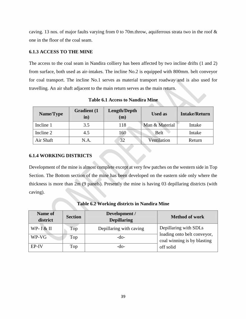
6.1.3 ACCESS TO THE MINE
The access to the coal seam in Nandira colliery has been affected by two incline drifts (1 and 2)
from surface, both used as air-intakes. The incline No.2 is equipped with 800mm. belt conveyor
for coal transport. The incline No.1 serves as material transport roadway and is also used for
travelling. An air shaft adjacent to the main return serves as the main return.
Table 6.1 Access to Nandira Mine
Name/Type Gradient (1
in)
Length/Depth
(m) Used as Intake/Return
Incline 1 3.5 118 Man & Material Intake
Incline 2 4.5 160 Belt Intake
Air Shaft N.A. 32 Ventilation Return
6.1.4 WORKING DISTRICTS
Development of the mine is almost complete except at very few patches on the western side in Top
Section. The Bottom section of the mine has been developed on the eastern side only where the
thickness is more than 2m (9 panels). Presently the mine is having 03 depillaring districts (with
caving).
Table 6.2 Working districts in Nandira Mine
Name of
district Section
Development /
Depillaring Method of work
WP- I & II Top Depillaring with caving Depillaring with SDLs
loading onto belt conveyor,
coal winning is by blasting
off solid
WP-VG Top -do-
EP-IV Top -do-
40
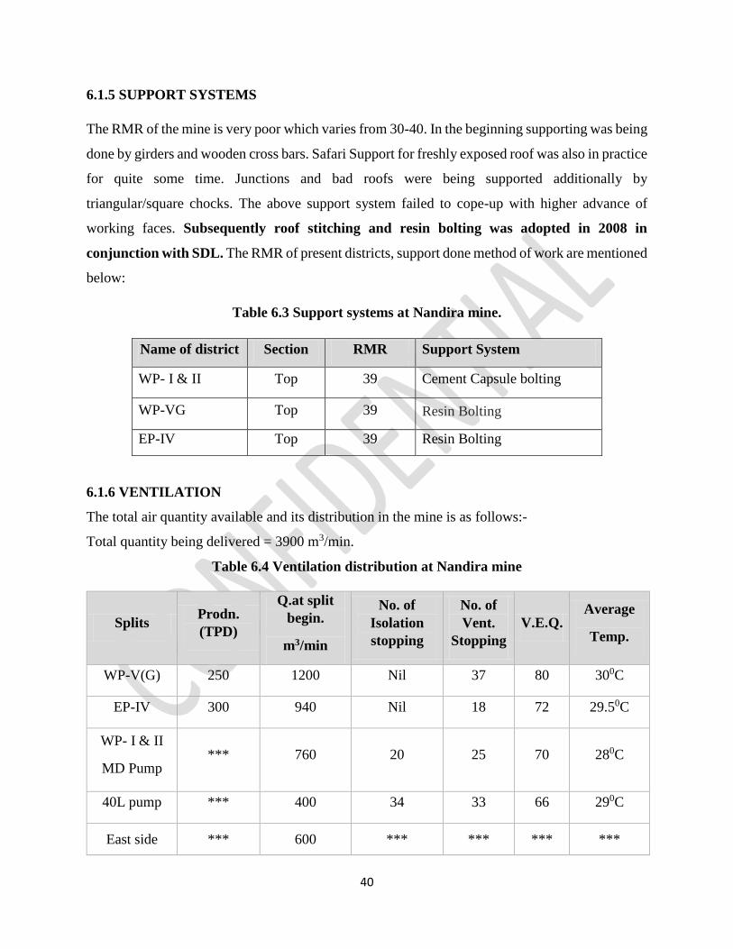
6.1.5 SUPPORT SYSTEMS
The RMR of the mine is very poor which varies from 30-40. In the beginning supporting was being
done by girders and wooden cross bars. Safari Support for freshly exposed roof was also in practice
for quite some time. Junctions and bad roofs were being supported additionally by
triangular/square chocks. The above support system failed to cope-up with higher advance of
working faces. Subsequently roof stitching and resin bolting was adopted in 2008 in
conjunction with SDL. The RMR of present districts, support done method of work are mentioned
below:
Table 6.3 Support systems at Nandira mine.
6.1.6 VENTILATION
The total air quantity available and its distribution in the mine is as follows:-
Total quantity being delivered = 3900 m3/min.
Table 6.4 Ventilation distribution at Nandira mine
Splits Prodn.
(TPD)
Q.at split
begin.
m3/min
No. of
Isolation
stopping
No. of
Vent.
Stopping
V.E.Q. Average
Temp.
WP-V(G) 250 1200 Nil 37 80 300C
EP-IV 300 940 Nil 18 72 29.50C
WP- I & II
MD Pump *** 760 20 25 70 280C
40L pump *** 400 34 33 66 290C
East side *** 600 *** *** *** ***
Name of district Section RMR Support System
WP- I & II Top 39 Cement Capsule bolting
WP-VG Top 39 Resin Bolting
EP-IV Top 39 Resin Bolting
41
Where,
V.E.Q. is the Ventilation Efficient Quotient of the ventilating district and can be expressed
mathematically as,
(V.E.Q.) =
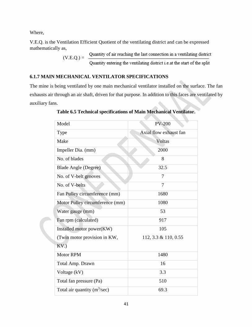
6.1.7 MAIN MECHANICAL VENTILATOR SPECIFICATIONS
The mine is being ventilated by one main mechanical ventilator installed on the surface. The fan
exhausts air through an air shaft, driven for that purpose. In addition to this faces are ventilated by
auxiliary fans.
Table 6.5 Technical specifications of Main Mechanical Ventilator.
Model PV-200
Type Axial flow exhaust fan
Make Voltas
Impeller Dia. (mm) 2000
No. of blades 8
Blade Angle (Degree) 32.5
No. of V-belt grooves 7
No. of V-belts 7
Fan Pulley circumference (mm) 1680
Motor Pulley circumference (mm) 1080
Water gauge (mm) 53
Fan rpm (calculated) 917
Installed motor power(KW)
(Twin motor provision in KW,
KV.)
105
112, 3.3 & 110, 0.55
Motor RPM 1480
Total Amp. Drawn 16
Voltage (kV) 3.3
Total fan pressure (Pa) 510
Total air quantity (m3/sec) 69.3
42
Motor current (amp) 16
Supply voltage (V) 3300
Estimated power factor 0.9
Air power (kW) 35
Motor power input (kW) 82
Overall system efficiency (%) 43
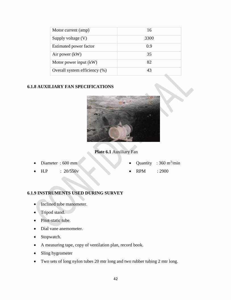
6.1.8 AUXILIARY FAN SPECIFICATIONS
Plate 6.1 Auxiliary Fan
Diameter : 600 mm
H.P : 20/550v
Quantity : 360 m3/min
RPM : 2900
6.1.9 INSTRUMENTS USED DURING SURVEY
Inclined tube manometer.
Tripod stand.
Pitot-static tube.
Dial vane anemometer.
Stopwatch.
A measuring tape, copy of ventilation plan, record book.
Sling hygrometer
Two sets of long nylon tubes 20 mtr long and two rubber tubing 2 mtr long.
43
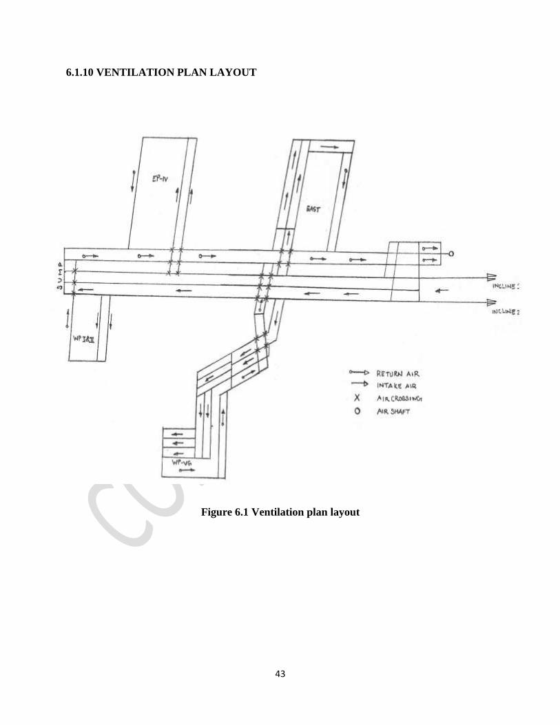
6.1.10 VENTILATION PLAN LAYOUT
Figure 6.1 Ventilation plan layout

44
Figure 6.2 Schematic diagram of ventilation systems with nodes.

45
6.1.11 FIELD SURVEY READINGS
A total of 40 nodes were selected, based on which the measurement was taken.
Table 6.6 Field survey readings
Sl
No. Station
Quantity
(m3/s)
Press.
(Pa)
Resistance
(Ns2/m8)
Press.
(mmH20)
X-Sec
Area
(m2)
DBT
(0C)
WBT
(0C)
RH
(% )
1 1-3 43.9 64.2 0.03331 6.5484 9.45 18.9 17.0 86.0
2 2-3 24.3 64.2 0.10872 6.5484 2.03 19.2 17.8 87.4
3 3-4 64.75 33.6 0.00801 3.4272 5.0 19.3 17.8 86.3
4 4-5 64.61 19.7 0.00472 2.0094 12.0 19.6 17.9 88.0
5 5-5’ 51.03 0.7 0.00026 0.0714 4.94 23.1 21.4 86.4
6 5-6 14.35 23.3 0.11315 2.3766 10.5 20.2 18.0 82.4
7 5’-6’ 13.3 22.8 0.12889 2.3256 7.85 21.0 19.3 86.4
8 6’-7 27.65 15.9 0.02079 1.6218 7.9 21.1 19.5 87.2
9 7-8 11.4 13.7 0.10541 1.3974 7.6 23.4 21.6 85.6
10 7-9 15.86 7.7 0.03061 0.7854 13.0 25.3 22.9 78.4
11 9-10 23.82 4.9 0.00863 0.4998 6.30 28.0 27.3 87.0
12 10-10’ 11.59 3.7 0.02754 0.3774 7.22 29.0 28.5 92.6
13 10-11 12.23 4.9 0.03275 0.4998 5.80 28.4 28.0 95.0
14 11/1-12 7.44 0.3 0.00542 0.0306 6.20 28.3 27.4 90.0
15 11/2-13 5.89 0.2 0.00576 0.0204 9.50 28.3 27.2 87.6
16 11/3-14 3.4 0.4 0.03460 0.0408 6.82 26.5 25.0 86.3
17 14-15 17.8 6.6 0.02083 0.6732 6.25 23.6 22.2 88.8
18 15-16 28 4.7 0.00599 0.4794 5.44 27.8 25.8 82.0
19 16-17 27.95 3.4 0.00435 0.3468 5.92 28.6 27.4 90.0
20 17-18 9.9 24.9 0.25405 2.5398 6.21 28.0 26.5 86.5
21 18-20 9.9 24.9 0.25405 2.5398 6.12 26.4 24.8 85.6
22 17-19 18.05 24.5 0.07519 2.499 6.42 23.3 21.8 86.6
23 19-20 48.93 10 0.00417 1.02 5.22 22.6 21.0 87.9
24 20-21 58.83 6.7 0.00193 0.6834 5.40 27.4 26.5 93.7
25 5-23 2.70 151 20.0000 2.04 3.84 21.4 19.7 86.4
26 5’-22 5.02 103.5 4.00000 0.4080 6.43 22.8 21.0 85.6
27 23-24 7.34 3.6 0.06682 0.3672 4.82 24.8 22.3 79.7
28 24-25 7.524 9.4 0.16604 0.9588 6.84 26.1 24.5 88.8
29 5’-26 30.02 7.7 0.00854 0.7854 7.2 24.2 22.1 83.2
30 26-26’ 19.47 2.9 0.00764 0.2958 6.0 26.6 24.8 87.3
31 26-27 10.54 3.2 0.02881 0.3264 6.80 26.4 24.6 87.4
32 26’-28 9.03 3 0.03679 0.306 6.02 28.9 28.4 95.0
33 28-29 15.66 0.3 0.00122 0.0306 9.25 26.7 24.9 86.9
34 29-30 18.65 0.2 0.00057 0.0204 5.04 23.5 20.9 79.2
35 26’-31 10.45 7.8 0.07148 0.7956 7.36 27.3 24.7 81.8
36 31-31’ 6.59 1.9 0.04380 0.1938 12.0 21.7 19.8 84.8
37 31’-33 4.31 5.2 0.27993 0.5304 13.25 25.6 23.6 86.0
46
38 31-32 3.86 5.5 0.36913 0.561 12.09 24.2 22.1 83.2
39 31’-36 3.3 15.4 1.41414 1.5708 10.31 25.4 23.8 88.8
40 32-34 3.86 3.5 0.23490 0.357 6.68 25.5 24.2 90.9
41 34-35 8.14 1.9 0.02867 0.1938 5.25 25.1 23.0 85.2
42 36-37 3.3 0.8 0.07346 0.0816 8.46 26.8 25.6 90.8
43 37-35 3.3 0.7 0.06427 0.0714 7.26 27.5 26.6 93.7
44 35-30 11.44 0.2 0.00153 0.0204 6.50 27.6 26.6 93.0
45 30-19 30.88 10.3 0.01080 1.0506 8.42 27.2 26.5 95.0
46 21-25 58.83 6.9 0.00199 0.7038 5.38 28.0 27.2 94.0
47 25-38 66.35 51.5 0.001169 5.253 6.82 28.8 28.1 95.1
48 38-39 67.2 19.3 0.00427 1.9686 7.64 28.9 27.2 88.0
49 39-40 68.2 319 0.06858 32.538 11.0 29.7 27.9 87.4
50 40-1 68.4 0 0.00000 0 12.56 18.7 16.8 82.0
6.2 ANALYSIS
6.2.1 VENTSIM VISUAL- ADVANCED VERSION
Ventsim is an electronic checking and control framework programming, which gives prompt or
constant data about every branch in an underground ventilation system. It is developed and
distributed by Chasm Consulting based in Australia and marketed in India by Data mine
International Ltd. These framework measures the air quantity and pressure changes in the
ventilation branches for the input values and simulate the model through all different branches.
Ventsim represents an actual ventilation conditions of the existing mine. Without a correct
representation of existing conditions, the model could lead to incorrect results for the purpose of
planning future design. For which validating the model with accurate data is necessary. Accuracy
here means the difference between modelled air quantity pressure data’s and actually measured
data’s. Accurate resistances depend s upon accuracy of complete pressure survey. This accuracy
may from 90-95% depending upon quality of input data into Ventsim model. Theoretically in a
Ventsim model, output simulation will be perfect if input data is perfect. Ventsim uses the Hardy
Cross Algorithm for achieving accuracy within the tolerance limit for simulation error. Ventsim
uses standard design size and default friction factors and shock losses to design because the above
mentioned parameters are always not exactly known. This ensures 85-90% accuracy with pressure
surveys for not being able to measure actual resistances [23].
47
Ventsim likewise permits attributes like heat, gas and other contaminant levels for production
purposes. A fitting adjust in air flow and well maintained splits are kept up. An entire model of
ventilation framework can be made once the pressure quantity survey readings are entered.
Hardy Cross Algorithm
This algorithm is used to solve complex ventilation networks in which suitable quantities for
different branches are assumed giving due consideration to Kirchhoff’s first law i.e. law of
continuity of flow. The closer the assumed quantities to be true the less is the number of successive
iterations.
This algorithm have been developed by Hardy Cross a Professor in the University of Illinois, had
developed the technique in1936 for application in water distribution systems [24].
Advantages of using Ventsim are:-
(a) Determine the effectiveness of ventilation design of the underground mine by proper
monitoring.
(b) In case of incorrect entries or improper data details, it indicates the airway number along
with the type of problem existed.
(c) Helps in monitoring of leakage in the goaf side due to sudden change of air quantity.
(d) Detects any sort of blockage in the airway.
(e) Performance of fan can be monitored on real time data’s and suggests in providing an
optimal solution to the fan installation or changes.
(f) Gives a successful way out course bearing if there should arise an occurrence of crisis for
underground faculty and rescue group for departure.
(g) Save time lost in measurement and checking of underground ventilation by mine officials.
(h) Detects failure of regulators and sudden changes in differential pressure.
(i) Detects in failure of stopping to prevent any potential spontaneous combustion.

48
6.2.2 SIMULATION RESULTS AND SURVEY DATA’S COMPARISON
Table 6.7 Estimation of leakages
Sl. No. Station
Quantity
Field-Survey
(m3/s)
Quantity
Ventsim
(m3/s)
Difference in
Quantity/Leakages
(m3/s)
Difference in
Fraction w.r.t
Qty-Survey
1 1-3 43.9 44 0.1 0.002278
2 2-3 24.3 24.3 0 0.000000
3 3-4 64.75 68.2 3.45 0.053282
4 4-5 64.61 68.2 3.59 0.055564
5 5-5’ 51.03 50.8 0.23 0.004507
6 5-6 14.35 14.7 0.35 0.024390
7 5’-6’ 13.3 13.3 0 0.000000
8 6’-7 27.65 28 0.35 0.012658
9 7-8 11.4 12.9 1.5 0.131579
10 7-9 15.86 15.1 0.76 0.047919
11 9-10 23.82 28 4.18 0.175483
12 10-10’ 11.59 13.3 1.71 0.147541
13 10-11 12.23 14.7 2.47 0.201962
14 11/1-12 7.44 7.6 0.16 0.021505
15 11/2-13 5.89 7.9 2.01 0.341256
16 11/3-14 3.4 12.5 9.1 2.676471
17 14-15 17.8 18 0.2 0.011236
18 15-16 28 28 0 0.000000
19 16-17 27.95 28 0.05 0.001789
20 17-18 9.9 12.7 2.8 0.282828
21 18-20 9.9 12.7 2.8 0.282828
22 17-19 18.05 15.3 2.75 0.152355
23 19-20 48.93 47.8 1.13 0.023094
24 20-21 58.83 60.4 1.57 0.026687
25 5-23 3.32 2.7 0.62 0.186747
26 5’-22 5.02 5.1 0.08 0.015936
27 23-24 7.34 7.8 0.46 0.062670
28 24-25 7.524 7.8 0.276 0.036683
29 5’-26 30.02 32.4 2.38 0.079280
30 26-26’ 19.47 21.8 2.33 0.119671
31 26-27 10.54 10.6 0.06 0.005693
32 26’-28 9.03 9.9 0.87 0.096346
33 28-29 15.66 20.6 4.94 0.315453
34 29-30 18.65 20.6 1.95 0.104558
35 26’-31 10.45 11.8 1.35 0.129187
36 31-31’ 6.59 8.1 1.51 0.229135
37 31’-33 4.31 4.5 0.19 0.044084
38 31-32 3.86 3.8 0.06 0.015544
39 31’-36 3.3 3.6 0.3 0.090909
40 32-34 3.86 3.8 0.06 0.015544

49
41 34-35 8.14 8.2 0.06 0.007371
42 36-37 3.3 3.6 0.3 0.090909
43 37-35 3.3 3.6 0.3 0.090909
44 35-30 11.44 11.8 0.36 0.031469
45 30-19 30.88 32.4 1.52 0.049223
46 21-25 58.83 60.4 1.57 0.026687
47 25-38 66.35 68.2 1.85 0.027882
48 38-39 67.2 68.2 1 0.014881
49 39-40 68.2 68.2 0 0.000000
50 40-1 68.4 69 0.6 0.008772
AVERAGE=13.145%
6.2.3 VENTSIM MODELLING
Figure 6.3 (i) Ventsim model design of the ventilation network of the coal mine
9

50
Figure 6.3 (ii) Simulated model design of the ventilation network of Nandira
coal mine
51
6.2.4 FAN CHARACTERISTICS
Figure 6.4 Characteristics curve of MMV
The mean efficiency from the above fan characteristic was found to be 42.85 %.
Figure 6.5 Fan characteristic curve and operating point
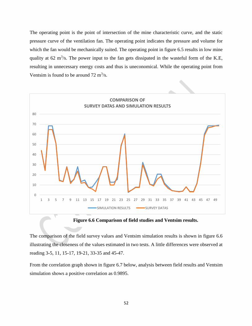
52
The operating point is the point of intersection of the mine characteristic curve, and the static
pressure curve of the ventilation fan. The operating point indicates the pressure and volume for
which the fan would be mechanically suited. The operating point in figure 6.5 results in low mine
quality at 62 m3/s. The power input to the fan gets dissipated in the wasteful form of the K.E,
resulting in unnecessary energy costs and thus is uneconomical. While the operating point from
Ventsim is found to be around 72 m3/s.
The comparison of the field survey values and Ventsim simulation results is shown in figure 6.6
illustrating the closeness of the values estimated in two tests. A little differences were observed at
reading 3-5, 11, 15-17, 19-21, 33-35 and 45-47.
From the correlation graph shown in figure 6.7 below, analysis between field results and Ventsim
simulation shows a positive correlation as 0.9895.
0
10
20
30
40
50
60
70
80
1 3 5 7 9 11 13 15 17 19 21 23 25 27 29 31 33 35 37 39 41 43 45 47 49
COMPARISON OFSURVEY DATAS AND SIMULATION RESULTS
SIMULATION RESULTS SURVEY DATAS
Figure 6.6 Comparison of field studies and Ventsim results.
53
Figure 6.7 Correlation analysis of field studies and Ventsim results.
6.2.5 OBSERVATIONS
The air velocity in branch node have been compared in both the field survey readings and
simulation results. The air velocity found in field readings are comparatively lower than simulation
results due to high resistances and obstructions in the mine.
Table 6.8 Velocity analysis in branch nodes.
Sl.
No. Station
Press.
(Pa)
X-Sec
Area
(m2)
Velocity
(m/s)
Ventsim
Velocity
(m/s)
survey
RH
(% )
1 1-3 64.2 9.45 4.65 4.64 86.0
2 2-3 64.2 2.03 11.97 11.9 87.4
3 3-4 33.6 5.0 13.64 12.95 86.3
4 4-5 19.7 12.0 5.68 5.38 88.0
5 5-5’ 0.7 4.94 10.28 10.32 86.4
6 5-6 23.3 10.5 1.40 1.36 82.4
7 5’-6’ 22.8 7.85 1.69 1.69 86.4
8 6’-7 15.9 7.9 3.54 3.50 87.2
9 7-8 13.7 7.6 1.69 1.50 85.6
10 7-9 7.7 13.0 1.16 1.22 78.4
11 9-10 4.9 6.30 4.44 3.78 87.0

54
12 10-10’ 3.7 7.22 1.84 1.60 92.6
13 10-11 4.9 5.80 2.53 2.10 95.0
14 11/1-12 0.3 6.20 1.22 1.20 90.0
15 11/2-13 0.2 9.50 0.83 0.62 87.6
16 11/3-14 0.4 6.82 1.83 0.49 86.3
17 14-15 6.6 6.25 2.88 2.84 88.8
18 15-16 4.7 5.44 5.14 5.14 82.0
19 16-17 3.4 5.92 4.72 4.72 90.0
20 17-18 24.9 6.21 2.04 1.59 86.5
21 18-20 24.9 6.12 2.07 1.61 85.6
22 17-19 24.5 6.42 2.38 2.81 86.6
23 19-20 10 5.22 9.15 9.37 87.9
24 20-21 6.7 5.40 11.18 10.89 93.7
25 5-23 151 3.84 0.70 0.86 86.4
26 5’-22 103.5 6.43 0.79 0.78 85.6
27 23-24 3.6 4.82 1.61 1.52 79.7
28 24-25 9.4 6.84 1.14 1.10 88.8
29 5’-26 7.7 7.2 4.50 4.16 83.2
30 26-26’ 2.9 6.0 3.63 3.245 87.3
31 26-27 3.2 6.80 1.55 1.55 87.4
32 26’-28 3 6.02 1.64 1.50 95.0
33 28-29 0.3 9.25 2.22 1.69 86.9
34 29-30 0.2 5.04 4.08 3.70 79.2
35 26’-31 7.8 7.36 1.60 1.41 81.8
36 31-31’ 1.9 12.0 0.67 0.54 84.8
37 31’-33 5.2 13.25 0.33 0.32 86.0
38 31-32 5.5 12.09 0.31 0.31 83.2
39 31’-36 15.4 10.31 0.35 0.32 88.8
40 32-34 3.5 6.68 0.56 0.57 90.9
41 34-35 1.9 5.25 1.56 1.55 85.2
42 36-37 0.8 8.46 0.42 0.39 90.8
43 37-35 0.7 7.26 0.49 0.45 93.7
44 35-30 0.2 6.50 1.81 1.76 93.0
45 30-19 10.3 8.42 3.84 3.66 95.0
46 21-25 6.9 5.38 11.22 10.93 94.0
47 25-38 51.5 6.82 10.00 9.72 95.1
48 38-39 19.3 7.64 8.92 8.79 88.0
49 39-40 319 11.0 6.20 6.20 87.4
50 40-1 0 12.56 5.49 5.44 82.0
55
CHAPTER 7
CONCLUSIONS
7.1 CONCLUSIONS
From the results obtained, correlation analysis, comparison of the field data and simulation values
the followings points are observed.
Maximum leakage is observed to be 4.94 m3/sec at the nodes 28-29 in EP-IV panel near the
goaf area and zero leakage is observed at nodes 2-3, 5’-6’, 15-16 and 39-40.
The field readings and simulation results have a positive correlation of 0.9895.
The Relative Humidity (R.H) is maximum of 95.1 % at node 25-38.The Relative Humidity
(R.H) is minimum of 78.4 % at node 7-8.
Least velocity of air in field survey is observed at node 31-32 with a velocity of 0.21 ms-1 and
maximum velocity at node 3-4 (intake air) with a velocity of 12.95 ms-1.
Least velocity of air in Ventsim simulation is also observed at node 31-32 with a velocity of
0.21 ms-1 and maximum velocity at node 3-4 (intake air) with a velocity of 13.64 ms-1.
Differential Pressure is observed least to be at nodes 11/2-13, 29-30 and 35-30 with a value of
0.2 Pa and maximum to be at nodes 5-23 and 5’-22 with a value of 151 Pa and 103.5 Pa. Also
at node 39-40 beyond MMV with a value of 319 Pa.
Simulation results and Field readings differs overall with an average of 13.145 % as a result of
resistances faced during field survey due to movement of tubs, leakages, working hours of the
personnel , instrumental errors and faulty Air Measuring Stations.
It is also observed that at nodes 31’-33 and 31-32 (working faces) of district WP I & II the velocity
of air is flowing at 0.32 and 0.31 ms-1 which is below the DGMS recommended level for air
velocity of 0.5 ms-1 (Table 3.4). This problem can be solved by-
Installation of an additional air shaft or booster fan will gradually increase the air flow in the
places.
An effective construction of ventilation stoppings at intake air-route will ensure minimal loss
of fresh air at the stoppings.
56
Use of regulator at crossover will ensure effective distribution of air quantity and minimize
losses.
Enlarge the cross sectional areas of the roadways and make them smooth lined.
Speed up the surface fan.
7.2 RECOMMENDATIONS
Based on the existing ventilation problems at Nandira mine, the following recommendations were
suggested
Calibration of pressure measuring instrument at regular interval is required for accurate periodic
survey.
Removing the blockage if not necessary at the return airways.
Air should be properly coursed up to faces with the help of auxiliary ventilators.
The existing PV-200 fan is to be replaced by a fan of 100m3/sec of air quantity.
Air should be properly coursed up to LVC (Last Ventilation Connection) of the district by
strengthening the stoppings and doors (minimize the leakages).
In the district, air from LVC should be coursed up to the faces by auxiliary ventilators.
Leakage roots are large in numbers causing a decrease in volumetric efficiency which can be
solved by increasing the pressure and minimize the leakages.
Maintenance of Air Measuring Stations at regular intervals.
57
REFERENCES
1. McPherson, M.J. (1983), Subsurface Ventilation and Environmental Engineering,
Netherlands: Kluwer Academic Publishers, pg.4.2-4.15, 6.1-6.20.
2. Misra, G.B. (2002), Mine Environment and Ventilation, New Delhi: Oxford University
Press, pg. 454- 562.
3. Ghatak, S. (1993), Mine Ventilation, Coal Field Publishers, West Bengal, India, Vol. II,
pg.126-135, 195-220.
4. Vutukuri V.S. and Lama R.D. (1986), Environmental Engineering in Mines. Cambridge,
Cambridge University Press, pg. 314-315.
5. Ray S.K., Sahay N., Singh R.P., Singh A K and Bhowmick B.C. (2002), Reversal of
underground mine ventilation, Journal of Mines, Metals & Fuels, 50 (9), pg. 339-344.
6. Sahay N., Ray S.K., Ahmad I., Varma N. K., Singh R. P. and Singh A. K. (2003),
Improvement in Ventilation in a fire affected mine, Journal of the South African Institute
of Mining and Metallurgy, 103. pg. 465-476.
7. Sahay N. ,Varma N. K., Ahmad I., Singh A. K., Ray S.K. and Singh, R. P. (2002), Chamber
method of ventilation - a proven technology for reducing leakage of air into the
goaf, Journal of Mines, Metals & Fuels, 50 (9), pg. 345-350.
8. Varma N. K., Sahay N., Ahmad I. and Sinha, A. (2009), Significance of ventilation system
design on fire with special reference to extensive and fire affected mine, Journal of Mines,
Metals & Fuels, 57 (11), pg. 413-417.
9. Rowland, J A. (2010), Survey Execution to Build a Ventilation Model, Australian Style, in
13th United States/North American Mine Ventilation Symposium, Hardcastle and
McKinnon (Eds.) Sudbury, Canada, June 2010.
10. Rowland, J A. (2011), Ventilation Surveys and Modelling - Execution and Suggested
Outputs, 11th Underground Coal Operators' Conference, University of Wollongong & the
Australasian Institute of Mining and Metallurgy, pg. 214-224.
11. Rowland, J A. (2009), Moving the Ventilation Report into the 21st Century, in Proceedings
of 9th Coal Operators’ Conference (Eds: N Aziz and J Nemcik). University of Wollongong
and the Australasian Institute of Mining and Metallurgy, 2009, pg.155-174.
58
12. Prasad, S.D. and Rakesh (1992), Legislation in Indian Mines-A Critical Appraisal, Vol.-II,
pg.1126-1127.
13. Deshmukh, D. J. (2008), Elements of Mining Technology, Vol. – II, Denett & Co., Nagpur,
India, pg. 3.23-3.26.
14. Banerjee S.P. (2003), Mine Ventilation, Lovely Prakashan, Dhanbad, India, pg. 318-332
15. Hartman H.L., Mutmansky J.M. and Wang Y.J. (1982), Mine Ventilation and Air
Conditioning, John Wiley & Sons, New York, pg. 186.
16. Kaku, L.C. (2013), Coal Mining Regulation-1957, Lovely Prakashan, pg. 194-201.
17. Akande J.M, Onifade M. and Aladejare EA. (2013), Determination of Airflow
Distributions in Okaba Underground Coal Mine, Journal of Mining World Express, USA,
Vol. 2, Issue 2, pg. 40 – 44.
18. Morla R., Tanguturi K. and Rao, A.M. (2012), Selection of optimum combination of fans
for bord and pillar coal mines, 12th Coal Operators' Conference, University of Wollongong
& the Australasian Institute of Mining and Metallurgy, pg.221-228.
19. Calizaya, F., Stephens, M., and Gillies, S. (2010), Utilization of booster fans in
underground coal mines, SME Preprint No. 10-095. Littleton, CO: SME. Annual Meeting
February 28-March 3, Phoenix, AZ, pg. 1.
20. Prosser B.S., and Loomis I.M. (2004), Measurement of frictional pressure differentials
during a ventilation survey, Proceedings of the 10th US Mine Ventilation Symposium,
University of Alaska, Anchorage, pg. 59-66.
21. Kaku, L.C. (1994), DGMS Circulars, Lovely Prakashan, pg.368-369.
22. http://nptel.ac.in
23. http://www.ventsim.com/training-support/tutorials/tutorial-validating-your-ventsim-
model.
24. Cross H. (1936), Analysis of Flow in Networks of Conduits or Conductors, Bull, Illinois
University. Eng. Exp. Stn. No, 286.
*************************