Automated Regulation of Mine Ventilation - saimm
6
Automated Regulation of Mine Ventilation By PENTTI SYNOPSIS The ventilation systom of the Pyhasalmi Mine is described. The nrine is located in an area where the annual atmospheric temperature may vary from +30°C to - 30°C, Natural ventilation causes serious difficulties because the underground mine is connected by drifts and finger raises to the bottom of the 120 m-deep open pit. The natural ventilation tends to make the ventilation net unstable. The paper describes how the instability characteristics of the ventilation not can be studied and how they have been taken into account wllcn automating the control of the ventilation. In addition, the software, hardware and costs of the system ar e described. TllC system consists of 12 automated ventilation doors, two mine fans, 8 elements for sensing the air flow and temperatures, a control panel and a process computer. INTRODUCTION The Pyhasalmi Mine of the Outokumpu Co. is one of the largest in Finland. At present 800 000 metric tons of copper, zinc and pyrite-ore are mined annually, of which almost two-thirds is mined underground. Over half a million tons of various concentrates are produced per year, of which 85 per cent is pyrite concentrate, 10 per cent zinc concentrate and five per cent copper concentrate. The pyrite concentrate is treated in the pyrite smelter of the company, yielding elemental sulphur, S02 gas, iron oxide cinders and electric power. The mine is located in central Finland, where the annual atmospheric temperature varies from + 30°C to - 30°e. The temperature variation results in ventilation problems because the open pit and underground stopes are connected by several ore passes and drifts on the bottom and sides of the open pit. Efficient air conditioning is also necessary because of the possibility of high concentrations of and H 2 S gases, which originate in pyrite-dust explosions, and because of the use of diesel machinery. In the air conditioning problem there are generally three kinds of vatiables: (i) Variables of the air composition. (ii) Variables describing the mine: lengths and cross-sections of drifts, raises and stopes and how these branches are connected to each other. (iii) Variables of the kinematics and physical state of the air everywhere in the mine. The variables in the first group are determined by the general atmospheric conditions and by the effects of explosions or blasting on the concentrations of dust and gases. The variables in the second group are defined when the mine is beingplanncd. Thus the variables of group (i), and partly of(ii), are, from the ventilation point of view, uncontrollable. The usual initial situation is that the ventilation net is given and the goal is to control some variables in the third group so as to. obtain a specified flow of fresh air to certain places in the mlne. Of the variables in groups (ii) and (ill), those which are to some extent dircetly controllable are the total air quantity blown into the mine, the mean air temperature in the mine, and the disttibution of the total air fl.ow in the {hUts. Because of the functional dependence between the pressure losses in the drifts and the respective air flows, the loss of pressure energy in the drifts is as indirectly controllable as the air flow. Technically, these variables are controlled by air-heating units, fans and ventilation doors. 267 For the ventilation of the Pyhasalrni Mine the most serious difficulty arises from the large seasonal variation in the atmospheric air temperature. This results in uncontrollable sources of natural ventilation pressure in the system. These sources tend to disturb the air circulation and make the system unstable in certain circumstances. Figure 1 is a diagranl of the mine. The air flow in the mine as a result of natural ventilation, when all ventilation doors are open and the fans are not functioning, is indicated by arrows. However, the desired air flows are, nearly everywhere, in the direction opposite to the fl.ows created by the natural ventilation, since during the winter the air is heated and blown down the ventilation shaft (on the left in Fig. 1). At present the major portion of the air is taken to level 210 and distributed to the stopes. A minor portion is currently led to level 400 in order to ventilate the crushing stations. Later, level 400 will be the main ventilation level. The air flows of the net vary from o to 200 000 m 3 /h and its temperature and relative humidity are, independent of the weather, 6 to SOC and greater than 90 per cent, respectively. The goal for the automation of the ventilation can now be stated as follows: Independently of the uncontrollable natural ventilation and the random disturbances from the operation of the mine, specified quantities of fresh air are to be blown to tlle work places. This also includes the requirement that the stapes must be ventilated after blasting. Besides the above goal there are the following constraints and auxiliary requirements for the solution of the problem: (i) The costs of heating the air should be minimized. CH) Freezing in any part of the mine should be prevented, (iii) The control elements (doors, fans) should not seriously disturb the traffie in the mine. (iv) The control system should be so designed that the goal can be maintained even after considerable drift and stope alterations in the mine. Familiarity with the stability characteristics of the ventilation net is of primary importance for automatic control of the ventilation. For this reason one example of the Pyhasalmi net will now be analyzed before the system currently in use on the mine is described. THE STABILITY OF THE VENTILATION A change in the resistance to air flow in anyone drift will result in changes in the air flow quantities, and possibly also in the direction of flow, in other branches of the ventilation net. Being able to predict the extent of these changes is *Mining Engim:er, Outokumpu Co., Helsinki, Finland. I I
Transcript of Automated Regulation of Mine Ventilation - saimm
Automated Regulation of Mine Ventilation
By PENTTI NISKANEN~
SYNOPSIS
The ventilation systom of the Pyhasalmi Mine is described. The nrine is located in an area where the annual atmospheric temperature may vary from +30°C to - 30°C, Natural ventilation causes serious difficulties because the underground mine is connected by drifts and finger raises to the bottom of the 120 m-deep open pit.
The natural ventilation tends to make the ventilation net unstable. The paper describes how the instability characteristics of the ventilation not can be studied and how they have been taken into account wllcn automating the control of the ventilation. In addition, the software, hardware and costs of the system are described. TllC system consists of 12 automated ventilation doors, two mine fans, 8 elements for sensing the air flow and temperatures, a control panel and a process computer.
INTRODUCTION
The Pyhasalmi Mine of the Outokumpu Co. is one of the largest in Finland. At present 800 000 metric tons of copper, zinc and pyrite-ore are mined annually, of which almost two-thirds is mined underground. Over half a million tons of various concentrates are produced per year, of which 85 per cent is pyrite concentrate, 10 per cent zinc concentrate and five per cent copper concentrate. The pyrite concentrate is treated in the pyrite smelter of the company, yielding elemental sulphur, S02 gas, iron oxide cinders and electric power.
The mine is located in central Finland, where the annual atmospheric temperature varies from + 30°C to - 30°e. The temperature variation results in ventilation problems because the open pit and underground stopes are connected by several ore passes and drifts on the bottom and sides of the open pit. Efficient air conditioning is also necessary because of the possibility of high concentrations of SO~ and H 2S gases, which originate in pyrite-dust explosions, and because of the use of diesel machinery.
In the air conditioning problem there are generally three kinds of vatiables:
(i) Variables of the air composition.
(ii) Variables describing the mine: lengths and cross-sections of drifts, raises and stopes and how these branches are connected to each other.
(iii) Variables of the kinematics and physical state of the air everywhere in the mine.
The variables in the first group are determined by the general atmospheric conditions and by the effects of explosions or blasting on the concentrations of dust and gases. The variables in the second group are defined when the mine is beingplanncd. Thus the variables of group (i), and partly of(ii), are, from the ventilation point of view, uncontrollable. The usual initial situation is that the ventilation net is given and the goal is to control some variables in the third group so as to. obtain a specified flow of fresh air to certain places in the mlne.
Of the variables in groups (ii) and (ill), those which are to some extent dircetly controllable are the total air quantity blown into the mine, the mean air temperature in the mine, and the disttibution of the total air fl.ow in the {hUts. Because of the functional dependence between the pressure losses in the drifts and the respective air flows, the loss of pressure energy in the drifts is as indirectly controllable as the air flow.
Technically, these variables are controlled by air-heating units, fans and ventilation doors.
267
For the ventilation of the Pyhasalrni Mine the most serious difficulty arises from the large seasonal variation in the atmospheric air temperature. This results in uncontrollable sources of natural ventilation pressure in the system. These sources tend to disturb the air circulation and make the system unstable in certain circumstances. Figure 1 is a diagranl of the mine. The air flow in the mine as a result of natural ventilation, when all ventilation doors are open and the fans are not functioning, is indicated by arrows. However, the desired air flows are, nearly everywhere, in the direction opposite to the fl.ows created by the natural ventilation, since during the winter the air is heated and blown down the ventilation shaft (on the left in Fig. 1). At present the major portion of the air is taken to level 210 and distributed to the stopes. A minor portion is currently led to level 400 in order to ventilate the crushing stations. Later, level 400 will be the main ventilation level. The air flows of the net vary from o to 200 000 m3/h and its temperature and relative humidity are, independent of the weather, 6 to SOC and greater than 90 per cent, respectively.
The goal for the automation of the ventilation can now be stated as follows:
Independently of the uncontrollable natural ventilation and the random disturbances from the operation of the mine, specified quantities of fresh air are to be blown to tlle work places. This also includes the requirement that the stapes must be ventilated after blasting. Besides the above goal there are the following constraints and auxiliary requirements for the solution of the problem:
(i) The costs of heating the air should be minimized. CH) Freezing in any part of the mine should be prevented,
(iii) The control elements (doors, fans) should not seriously disturb the traffie in the mine.
(iv) The control system should be so designed that the goal can be maintained even after considerable drift and stope alterations in the mine.
Familiarity with the stability characteristics of the ventilation net is of primary importance for automatic control of the ventilation. For this reason one example of the Pyhasalmi net will now be analyzed before the system currently in use on the mine is described.
THE STABILITY OF THE VENTILATION
A change in the resistance to air flow in anyone drift will result in changes in the air flow quantities, and possibly also in the direction of flow, in other branches of the ventilation net. Being able to predict the extent of these changes is
*Mining Engim:er, Outokumpu Co., Helsinki, Finland.
I I
important for the effective control of the net. We shall call these two responses the quantity instability and the direction instability. In this study we also consider the stability of the mean air flow. Rapid fluctuations due to the turbulent nature of the air flow or disturbances of short duration caused by traffic in the mine are considered to be 'noise'.
I +
OUTOKUMPU Co PYHASALMI MINE NATURAL VENTILATION Atmospheric temperature -1SoC Temperature in the mine +7°C
I --+----~
L_. __ . ____ J::-______ ~- _"0"'_ Fig. 1. Natural ventilation of the Pyhasalmi Mine. On the left is the ventilation shaft. Arrows indicate the tendency for air flow in cold
weather due to naturol ventilation pressures.
Furthermore, the opening of ventilation doors and changes in the natural ventilation pressure will change the pressure structure in the net so that a branch can be stable in some situations and unstable in others. The criteria for changes in stability can be studied using two wmputcr programs:
(i) The digital simulation model of the mine. The measurements in practice have proved the model to be sufficiently accurate for the simulations.
(ii) The computer program to localize branches which may be direction-unstable.
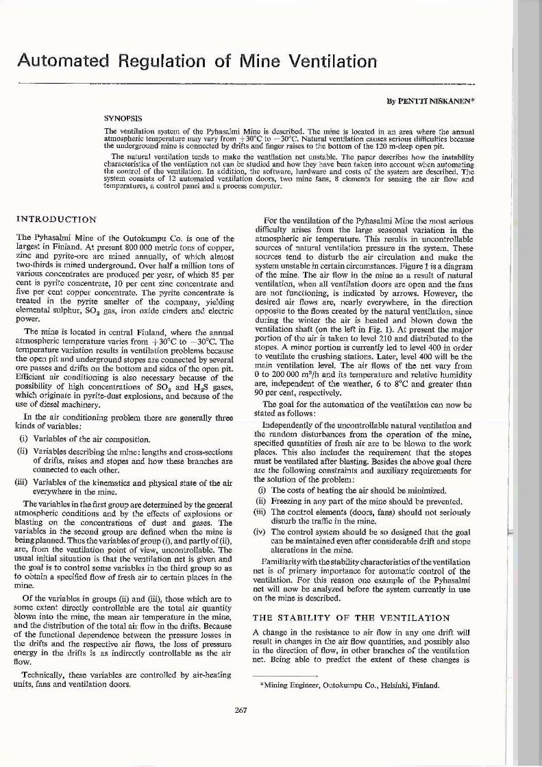
If the pressure decreases from A to B in Fig. 2 thcn branches 1 to 4 will have stable flowing directions whatever their air resistances are, but branch 5 has a special position in the net structure. When the resistances are increased in I or 4 it is possible that the pressure head Pl-~ will change and the air flow in branch 5 will be reversed. Such branches are called diagonal branches.
Diagonal branches are very common in complicated ventilation networks and it is difficult to locate them. Moreover, if the flow reverses in one diagonal branch then a change in
268
another branch or a complex of several branches may be possible. Thus the possibility of instability is ranked so that the first diagonal branch is ofjirst order and diagonal branches caused by the first one are higher~order diagonal branches. The first-order diagonal branches are the most unstable and only they are considered in this paper.
~ 1 ~
2 1
5
A 4 B
3
~ 2 ~ 3
Fig. 2. Branch 5 is a typical diagonal in the ventilation net. If the air resistance 0/1 or 4 is increased the /low in 5 can reverse.
A first~order diagonal branch need not necessarily be direction-unstable; it depends on the pressure structure of the net. Using the notations in Fig. 2 it can be stated that the diagonal branch is stable if
!:::.Ps !:::.P 2 K - > 1.
~l\ llP4
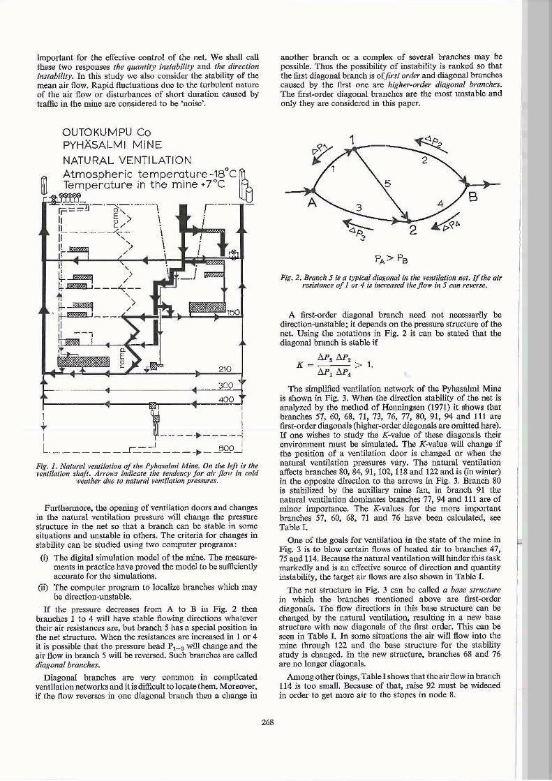
The simplified ventilation network of the PyhasaImi Mine is shown in Fig. 3. When the direction stability of the net is analyzed by the method of Henningsen (1971) it shows that branches 57, 60, 68, 71, 73, 76, 77, 80, 91, 94 and 111 are first-order diagonals (higher.order diagonals are omitted here). If one wishes to study the K~valuc of these diagonals their environment must be simulated. The K-value will change if the position of a ventilation door is changed or when the natural ventilation pressures vary. The natural ventilation affects branches 80, 84, 91, 102, 118 and 122 and is (in Winter) in the opposite direction to the arrows in Fig. 3. Branch 80 is stabilized by the auxiliary mine fan, in branch 91 the natural ventilation dominates branches 77, 94 and 111 are of minor importance. The K·values for the more important branches 57, 60, 68, 71 and 76 have boon calculated, see Table I.
One of the goals for ventilation in the state of the mine in Fig. 3 is to blow certain flows of heated air to branches 47, 75 and 114. Because the natural ventilation will hinder this task markedly and is an effective source of direction and quantity instability, the target air flows are also shown in Table I.
The net structure in Fig. 3 can be called a base structure in which the branches mentioned above are first~ordcr diagonals. The flow directions in this base structure can be changed by the natural ventilation, resulting in a new base structure with new diagonals of the first order. This can be seen in Table I. In some situations the air will flow into the mine through 122 and the base structure for the stability study is changed. In the new structure, branches 68 and 76 are no longer diagonals.
Amongother things, TableI shows that the airflow in branch 114 is too small. Because of that, raise 92 must be widened in order to get more air to the stopes in node 8.
Legend,
X vent. door
YreqUrable vent. door
~ mine fan
f21air quantity sensor
Fig. 3. Simplified ventilation net of the Pyhasalmi Mine. The air is blown into the mine from the atmosphere (node 1 down in the figure), Node 5 is the open pit and the stope areas are shown as nodes 6 and 8.
Furthermore, the table shows that diagonals 57 and 60 will not be unstable. This means that the respective ventilation doors will be effective for control in all situations,
The following stability characteristics can be stated as a summary: (i) The energy of the mine fans and the natural ventilation
together cause a base structure of the air flow in the mine. (ii) When the energy of the natural ventilation changes
sufficiently the air flow will reverse in some branches, resulting in a new base structure.
(in) When a particular base structure predominates the possible diagonal branches can be found and their sensitivity for instability can be evaluated.
(iv) When the characteristics of the mine change, the stability of the branches willchangeand anew study will be needed.
THE CONTROL SYSTEM
The present control system consists of the main mine fan, the heating units for blown air, one auxiliary fan and 12 automatic ventilation doors of which four can be regulated continuously. Control is possible either manually from a control panel or automatic.ll1y by a central control unit. The sensing elements are eight instruments for measuring air velocity, and thermometers. The control and sensing elements are connected by cables to the panel and from there will be connected to the computer. Door positions and air flow values are displayed on the panel (Fig. 5).
269
TABLE I
TIlE VARIATION OF TIlE AIR FLOW (Q) AND THE STABlLlTY COEFFICEINT (K) OF SOME BRANCHES IN FIG. 3 AS FUNCTION OF TIlE ATMOSPHERIC
'IEMPERATURE AND THE srATIlS OF VENTIlATION DOORS.
Opened Branch At mos heric tem roture doors .20 C +7°C -30 C
% K , K % K 53 100 9 4 66 57 16 10 15 10 10 7 60 7 86 8 102 9 246 68 31 4,4 31 4,4 43 stable
~ 71 11 1,2 11 1,3 27 1,2 ~
76 12 7 12 3,3 13 stable 47 20 21 23' 75 49 49 96
114 14 14 9
53 115 111 86 57 20 32 20 29 17 19 60 5 8 5 8 6 10
~ 68 45 stoble 46 stable 58 stable M' 71 -30 0,7 -36 0,6 -57 0.5 ~ 76 14 stable 13 stable 12 stable
47 17 17 17 75 13 7 17
114 18 18 15
53 71 67 43 57 51 2,3 52 2,4 31 1,9
0 60 13 1 ;1 18 1,2 36 2,6 L 0 68 49 6 50 7 57 stable 0 71 - 6 1,0 -10 1,0 -23 0,9 u - 76 17 4 18 4 16 stable D 47 48 47 44
75 36 35 52 114 -18 -17 11
Generally, the automated system works so that, depending on the current production (and requirements for air), the operating supervisor chooses a ventilation strategy from the panel. The required air flows and the states of the on/off doors are stored in tables in the computer's memory. The computer maintains the desired strategy by controlling the main mine fan and the four continnously adjustable doors so that the measured and required air flows are equal.
Ventilation strategies
The two separate stope areas (as nodes 6 and 8 in Fig. 3), the inclined ramp (branches 57, 68, 76) and the crushing station (47) are to be ventilated indiv:idually or in combination depending on the work in the mine. The combination of these demands makes seven different ventilation strategies. Because of the goal of minimizing the total air flow needed in winter, there is one more strategy for the case when the mine is not working.
Blasting situations
The automated ventilation doors are metallic roller doors and they must be opened before blasting is done in the mine. Because of this and the danger of pyrite dust explosions, blasting in the mine has been centralised at five blasting stations, from where the 12 automatic doors can be opened before firing. Furthermore, the computer will be informed about where blasting is going on. After blasting the computer will perform the desired 'blasting ventilation' strategy (in the current state three different possibilities) and then return to the ventilation strategy which was current before blasting operations.
Alteratlof/s if/ Ihe milIe
The ventilation net will chauge along with. changes in tile mioe and therefore also the most effective locations of vcntilation doors and air velocity sensors will change. Alterations in the ventilatiou uet in the coming five years have been simulated by the computer model in order to 10cutG the CUITCnt doors and air velocity sensors optimally. It is Also possible by simulation to predict the number of control and sensing elements needed in the future, which is important when planning the stem net of cables, dimensions of iusnument panels and the software of the system.
Because a ll the parameters of the system are stored as tables in the software, their value or number can be changed easily (Fig. 4).
t e ventilation system I I observat ions I measurements control pane~ lb~~t?~~gs~~[6'kJ
new logic fans, air chln~e of b last in~1 uantiUes,
tor Ih& te~alur slrl egy ven tila tion s.ysl~m s.do(l1"5
1 I_ ~rlred \ whieh ~slrate-gy I- s tales of belore I t ile on/off} strategy? inlel"~lJltkm
Y1rasured ;~~ange ~'!',I wich slale of state of on! blasting the Syslerry off doors ve~ti~ation
I
H"""d 1 '-'
$E"quen la keep the de r"9ulatlon sired blast-
! . ai r flows of air \tJal"l- iog venUla! I . Ilties i't. ion for a;
O(lniro\l. !e lime t
I _ ~rowed r '
doors and
L timlls for '" ai r flowl> } • l ime~tl
bl.a~Ung ?
~eni1~atlon ,. • ~ !ri
" .} . How.d mugins ?
(~ )"," '';00) P(llrlts
li[it on
~ the stale 01 Ih.sys tt'm report 0
_the ven ia ion s\istem FW_ 4. UJgic of the control system.
INSTRUMENTS AND CONTROL DEVICES
Control panel
I
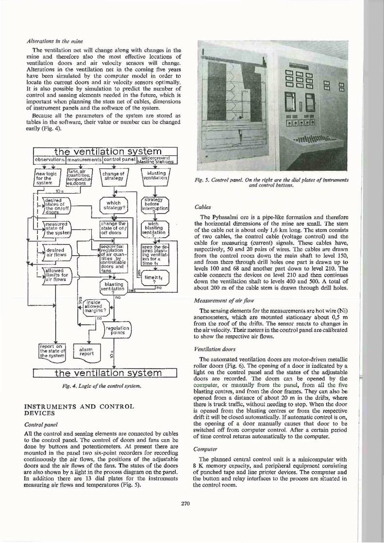
All the control and sensing elemenlS are connected by cables 10 the control panel. The control of doors and fans can be dono by buttons and potentiometers. At present there arc mounted in the panel two six-point recorders for recording continuously the air flows, the positions of the adjustable doors and the air flows of the fans. The states of the doors are also shown by a light in the process diagram on the panel. In additioo there are 13 dial plates for the instruments measuring air flows and temperatures (Fig. 5).
270
•
Frg. 5. umtro{ panel. On Ihe righr are the dial plates of instrumMts and control bUIlO"".
Cables
The Pyhasalmi ore is a pipe-like formation and therefore the horizontal dimensions of the mine are small. The stem of the cable net is about only 1,6 km long. The stem consists of two cables. the control cable (voltage control) and tbe cable for measuring (current) signals. These cables have, respectively, 50 and 20 pairs of wires. The cables are drawn from the control room dOWll the main shaft to level 150, and from there through drill holes one part is drawn up to levcls 100 and 68 and another part down to level 210. The cable CODDr-cts tbe devices ou level 210 and then continues down the ventilation shaft to levels 400 and 5{X). A total of about 200 m of the cable stem is drawn through drill boles.
Measurement of air flow
The sensing elements for the measurements are hot wire (Ni) anemometers, which are mounted stationary about 0,5 m from the roof of the drifts. The sensor reacts to changes in tbe air velocity. Their looters in the control panel are calibrated to show the respective ai r flows.
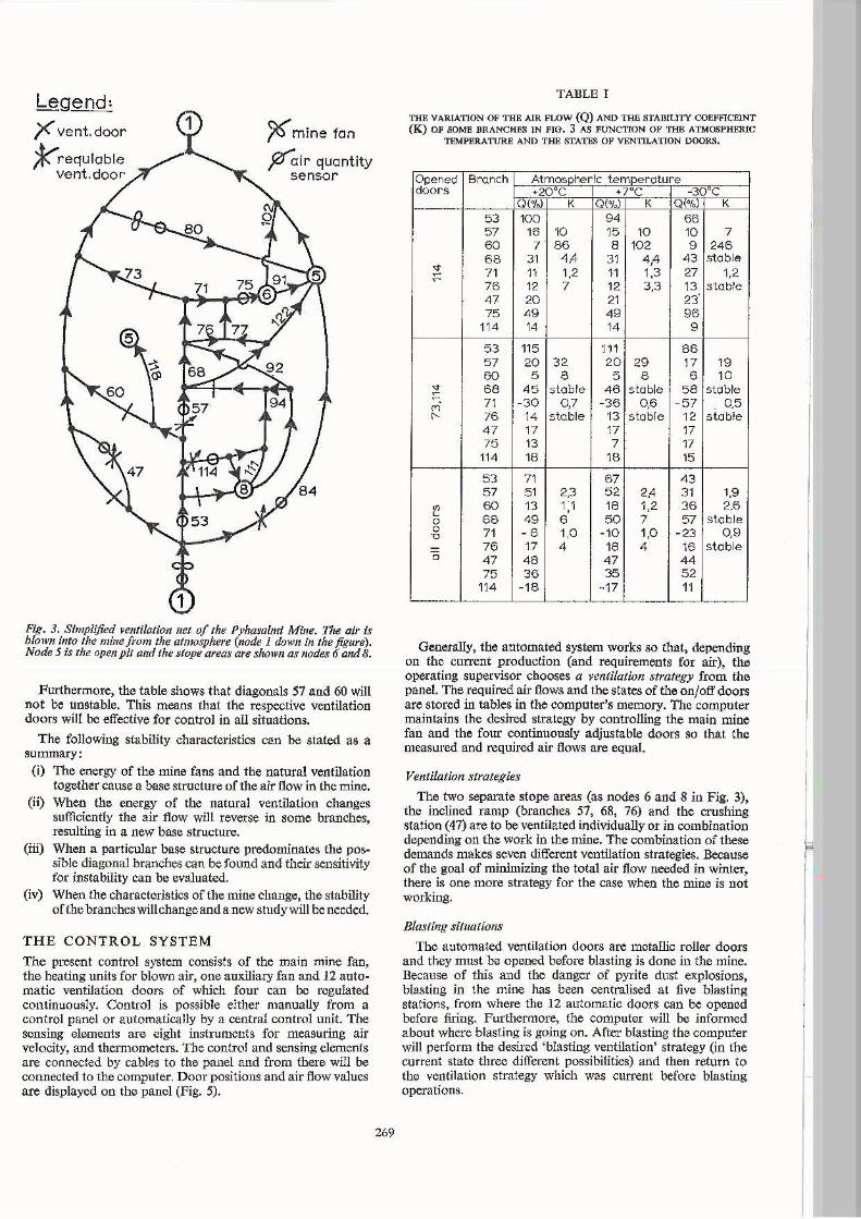
Ventilation doors
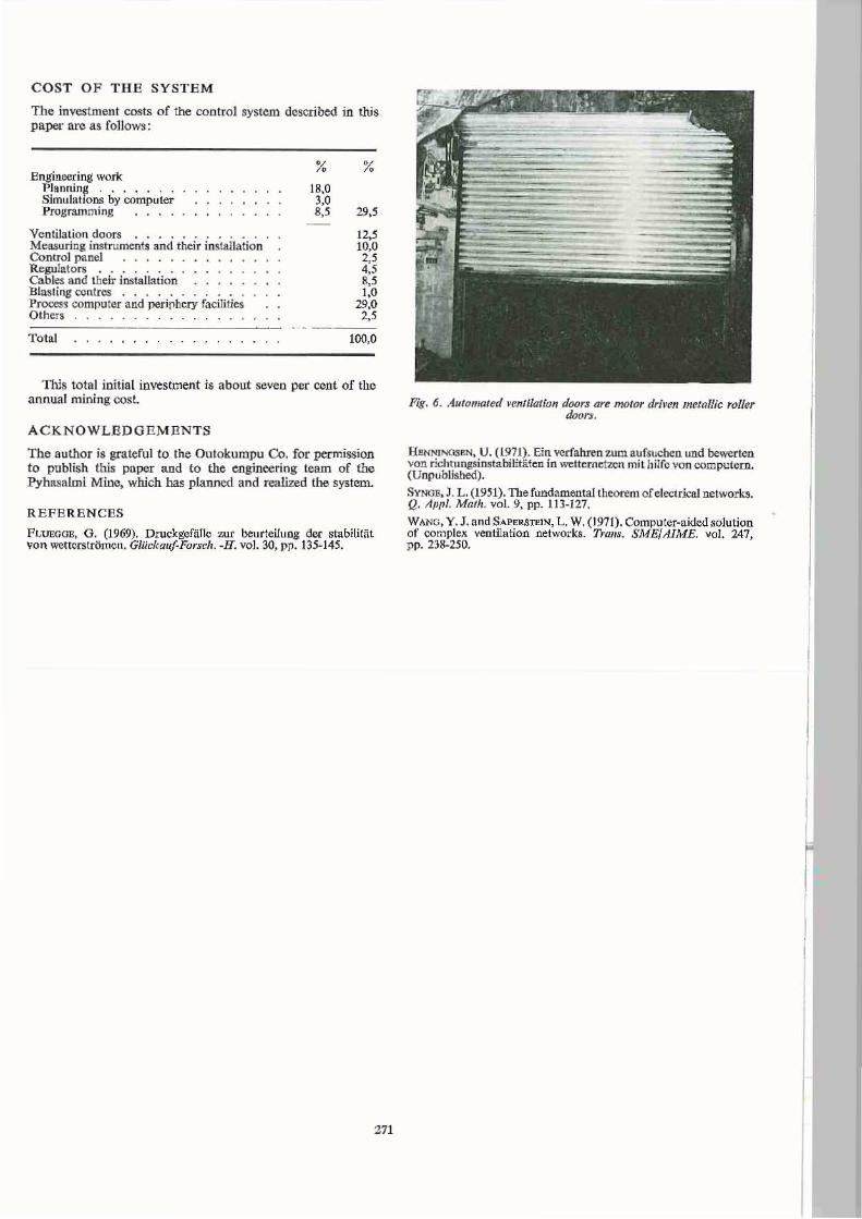
The automated ventilation doors are motor-driven metallic roller doors (Fig. 6). The opening of a door is indicated by a liaht ou the control panel aod the states of the adjustable doors are recorded. The doors can be opened by the computer, or manually from the panel, from all the five blasting centres, and from the door frames. They can also be opened from a distance of about 20 m in the drifts, where there is truck traffic, without needing to stop. When the door is opened from the blasting centres or from the respective drift it will be closed automatically. If automatic control is on, the opening of a door manually causes that door to be switched off from compUler control. After a certain period of time cootrol returns automaticaUy to the computer.
Compuler
The planned central control unit is a minicomputer with 8 K memory capacity, and peripheral equipment consisting of punched tape and line printer devices. The computer and the button and relay interfaces to tile process are situated in the control room.
COST OF TH E SYSTE M
The investment costs of the control system described in this paper arc as follows:
Engineering work Planninll . ..... . SimulatlOos by computer Programming
Ventilation doors ... MeasoriOi instrumc:nts and their instal latio n Connot pane] .... . . R egulators. ..... . .. . . Cable:$ and their iostaJL'uion Btasting centres . . . . . Pr0CCl!3 computer and periphery facilities Others
Total
%
18,0 3,0 8,'
%
29,5
12,5 10,0 2,5 4,5 ~5 1,0
29,0 2,5
100,0
TIlls tote] initial investment is about seven per cent of the annual mining cosL
ACKNOW LEDGEMENTS
The author is grateful to the OUlokumpu Co. for permission to publish this paper and to the engineering team of the Pyhasalmi Mioo, which has planned and realized the system.
REF E REN CES
FLUEGOE, O. (1969). Druckgefal1c zur beurteiluDg der stabilitfit von wettcrstr6mcn. Gltickau/-Forsr:h. -H. vol. 30, pp. 135-145.
271
Fig. 6. Au/onlO/ed Y~n/i/atio" door:; are fn()tor rfrj~'en metallic roller door:..
J.:(WNI"IQSIlN, U. (197J). Ein verfahren w m aufsuchen und bcwc:rten vcn richtungsinii1a bilit iiten in wc: lternelZ(ln mil hilrc von compulern . (Unpublished).
SVNOB, J. L. (1951). The fundamental theorem ofelectrkal network~. Q. Aflfll. Math. val. 9, pp. 113-127.
WANG, Y. J.andSAPElI.STElN, L. W. (.1971). Computer-aided solution of complex ventilation networks. Trails. SME/AIME. Vol. 247, pp. 238·250.

272