INVENTS: A Hybrid Mine Ventilation Planning and Design System · 1 Introduction The foundations of...
19
INVENTS: A Hybrid Mine Ventilation Planning and Design System Nikola Lilić, Ivan Obradović and Ranka Stanković Faculty of Mining and Geology University of Belgrade, Serbia
-
Upload
duongxuyen -
Category
Documents
-
view
222 -
download
2
Transcript of INVENTS: A Hybrid Mine Ventilation Planning and Design System · 1 Introduction The foundations of...
INVENTS: A Hybrid Mine Ventilation Planning and Design System Nikola Lilić, Ivan Obradović and Ranka Stanković
Faculty of Mining and Geology University of Belgrade, Serbia
1 Introduction
The foundations of quantitative planning of mine ventilation and of the design of appropriate ventilation system were set at the middle of the 19th century by the works of Atkinson (Hartman et al., 1997, McPherson, 1993). However, despite the introduction of various numerical and simulation methods in this process, mine ventilation planning and design practice still relies greatly on the intuition and expert knowledge of mine ventilation planners acquired through experience. The solution of the mine ventila-tion problem is a complex task which starts with the determination of the necessary volume of airflow needed for airing the workplaces within the mine, as well as of the air loss within the ventilation system. After airflow distribution is determined, its layout is marked on the mine plan and airflow velocities through mine workings are checked. In the next step, aerodynamic resistances within the workings are determined, as well as pressure drops due to air friction caused by the walls of the workings. Finally, pressure drops are also marked on the mine plan, and their sum along sequences of branches is calculat-ed, with the aim of determining the air path with the greatest pressure drop from the entry to the exit within the ventilation network as one of the main parameters of the ventilation network (Hartman et al., 1997, McPherson, 1993).
Recent approaches to mine ventilation planning and design rely substantially on information tech-nology. Various numerical and simulation methods, implemented within a number of software packages, have been at the disposition of mine ventilation planners in the process of mine ventilation planning and design for quite some time (McPherson, 1993, Oral, 1993, Ramani et al.,1990). On the other hand, soft-ware systems are more and more frequently evolving into intelligent systems by integrating artificial in-telligence methods (Jones, 2008). Some of these methods have also found their use in the mine ventila-tion planning and design area (Back et al., 2000). However, in order to cover all specific features of mine ventilation planning and design and reach a satisfactory solution various methods need to be combined. For example, due to engineering constraints, in some cases numerical and simulation methods fail to pro-duce a solution that is optimal and feasible at the same time, whereas such a solution can be reached by means of genetic algorithms (Yang et al., 1998a, Yang et al., 1998b, Lilić 1997b). In addition to that, an in-depth analysis of a candidate solution for the mine ventilation network needs domain expertise, which is when knowledge based methods come in handy (Lilić et al. 2002). Thus the software system devel-oped at the University of Belgrade, Faculty of Mining and Geology, presented in this paper, supports the implementation of a five-step approach to the solution of the mine ventilation planning and design prob-lem through a combination of numerical, simulation and AI methods. This integrated system builds on previously developed components: ResNet, SimVent and VENTEX (Lilić et al. 1997a). In each of them specific methods are applied to solve one or more tasks within the overall problem solving procedure. The basic outline of this approach can be illustrated by the component diagram depicted in Figure 1.
In the first, data acquisition step, extensive and exhaustive data on the mine are collected, in order to provide as much information as possible for the planning and design step. The second, system plan-ning and design step is the core step within the outlined approach. Within system planning, which is the introductory activity for the design process, key relations that need to be taken into account in the design phase are identified. In the subsequent, design phase, a ventilation system for the specific mine is pro-posed, that is, a ventilation network plan, supported by a corresponding database, which stores the venti-lation system design data. Implementation of the designed ventilation system and its maintenance, which follow, are aimed at securing optimal system effectiveness. After implementation, within the next step,
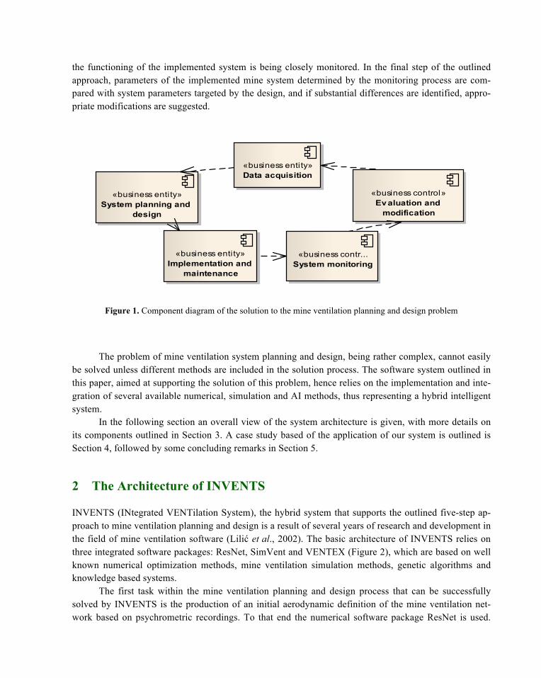
the functioning of the implemented system is being closely monitored. In the final step of the outlined approach, parameters of the implemented mine system determined by the monitoring process are com-pared with system parameters targeted by the design, and if substantial differences are identified, appro-priate modifications are suggested.
Figure 1. Component diagram of the solution to the mine ventilation planning and design problem
The problem of mine ventilation system planning and design, being rather complex, cannot easily
be solved unless different methods are included in the solution process. The software system outlined in this paper, aimed at supporting the solution of this problem, hence relies on the implementation and inte-gration of several available numerical, simulation and AI methods, thus representing a hybrid intelligent system.
In the following section an overall view of the system architecture is given, with more details on its components outlined in Section 3. A case study based of the application of our system is outlined is Section 4, followed by some concluding remarks in Section 5.
2 The Architecture of INVENTS
INVENTS (INtegrated VENTilation System), the hybrid system that supports the outlined five-step ap-proach to mine ventilation planning and design is a result of several years of research and development in the field of mine ventilation software (Lilić et al., 2002). The basic architecture of INVENTS relies on three integrated software packages: ResNet, SimVent and VENTEX (Figure 2), which are based on well known numerical optimization methods, mine ventilation simulation methods, genetic algorithms and knowledge based systems.
The first task within the mine ventilation planning and design process that can be successfully solved by INVENTS is the production of an initial aerodynamic definition of the mine ventilation net-work based on psychrometric recordings. To that end the numerical software package ResNet is used.
cmp Nov el design concept
«business entity»System planning and
design
«business entity»Implementation and
maintenance
«business contr...System monitoring
«business entity»Data acquisition
«business control»Ev aluation and
modification
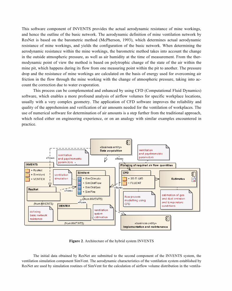
This software component of INVENTS provides the actual aerodynamic resistance of mine workings, and hence the outline of the basic network. The aerodynamic definition of mine ventilation network by ResNet is based on the barometric method (McPherson, 1993), which determines actual aerodynamic resistance of mine workings, and yields the configuration of the basic network. When determining the aerodynamic resistance within the mine workings, the barometric method takes into account the change in the outside atmospheric pressure, as well as air humidity at the time of measurement. From the ther-modynamic point of view the method is based on polytrophic change of the state of the air within the mine pit, which happens during its flow from one measuring point within the pit to another. The pressure drop and the resistance of mine workings are calculated on the basis of energy used for overcoming air friction in the flow through the mine working with the change of atmospheric pressure, taking into ac-count the correction due to water evaporation.
This process can be complemented and enhanced by using CFD (Computational Fluid Dynamics) software, which enables a more profound analysis of airflow volumes for specific workplace locations, usually with a very complex geometry. The application of CFD software improves the reliability and quality of the apprehension and verification of air amounts needed for the ventilation of workplaces. The use of numerical software for determination of air amounts is a step further from the traditional approach, which relied either on engineering experience, or on an analogy with similar examples encountered in practice.
Figure 2. Architecture of the hybrid system INVENTS
The initial data obtained by ResNet are submitted to the second component of the INVENTS system, the ventilation simulation component SimVent. The aerodynamic characteristics of the ventilation system established by ResNet are used by simulation routines of SimVent for the calculation of airflow volume distribution in the ventila-
tion network. However, the results produced by simulation are sometimes not applicable due to specific engineering constraints. A more flexible method is then needed, and it was found in the application of genetic algorithms. In brief, genetic algorithms are used within SimVent for determining the location and size of the so called “booster fans” within the mine ventilation system, thus producing a new solution for the airflow volume distribution in the ventila-tion network compliant to the aforementioned engineering constraints. The application of genetic algorithms will be further illustrated within the case study offered in Section 4 of this paper.
The third component of INVENTS is VENTEX – a knowledge based system that performs an analysis of the results obtained by SimVent following an evaluation strategy based on a number of criteria and using heuristics and knowledge acquired through engineering practice. Namely, based on the ventilation parameters proposed by ResNet and SimVent, VENTEX triggers a set of rules that perform an expert analysis and assessment of the global ventila-tion state of the network as well its specific features on basis of these parameters. If within the expert evaluation some features of the network are assessed as “bad” or “unfavorable”, VENTEX provides suggestions for modifica-tions and improvement of the ventilation network design aimed at yielding more favorable feature assessment.
The architecture of INVENTS was implemented within a software environment that provides for a flexible and dynamic communication between its components, and which will be described in more detail in the following section. The flexibility of the environment offers practically unlimited possibilities for testing different solutions for the mine ventilation system of a specific mine, until a feasible solution is reached, which ideally meets all the design criteria that were initially set.
3 Software Implementation
INVENTS was developed for computer systems running under MS Windows, following the basic guide-lines of the object-oriented approach in system structuring and modeling (Arlow et al., 2005). Compliant to this paradigm, UML (Unified Modeling Language), a standardized general-purpose modeling lan-guage for visualization, specification, constructing and documenting of data on software was used as a tool in the software development analysis phase.
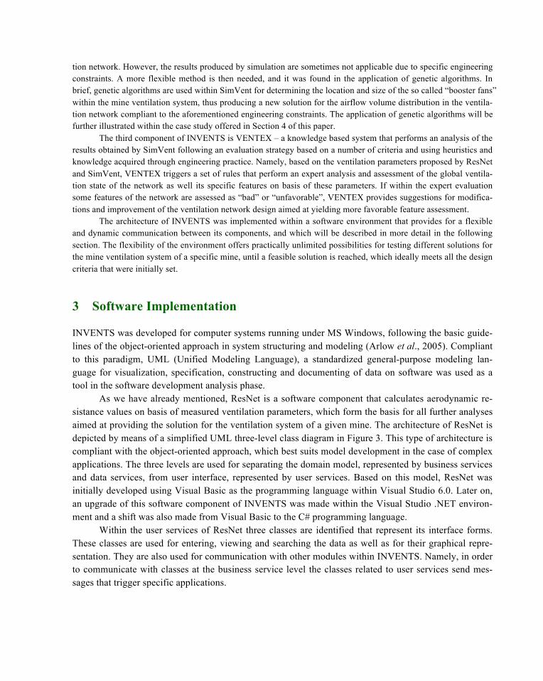
As we have already mentioned, ResNet is a software component that calculates aerodynamic re-sistance values on basis of measured ventilation parameters, which form the basis for all further analyses aimed at providing the solution for the ventilation system of a given mine. The architecture of ResNet is depicted by means of a simplified UML three-level class diagram in Figure 3. This type of architecture is compliant with the object-oriented approach, which best suits model development in the case of complex applications. The three levels are used for separating the domain model, represented by business services and data services, from user interface, represented by user services. Based on this model, ResNet was initially developed using Visual Basic as the programming language within Visual Studio 6.0. Later on, an upgrade of this software component of INVENTS was made within the Visual Studio .NET environ-ment and a shift was also made from Visual Basic to the C# programming language.
Within the user services of ResNet three classes are identified that represent its interface forms. These classes are used for entering, viewing and searching the data as well as for their graphical repre-sentation. They are also used for communication with other modules within INVENTS. Namely, in order to communicate with classes at the business service level the classes related to user services send mes-sages that trigger specific applications.
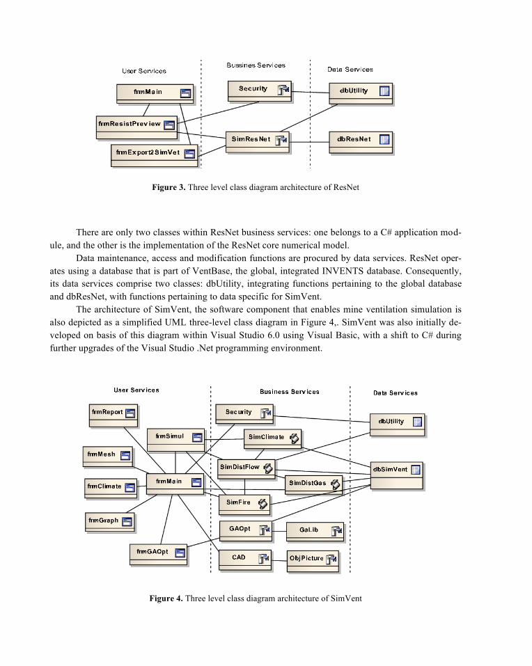
Figure 3. Three level class diagram architecture of ResNet
There are only two classes within ResNet business services: one belongs to a C# application mod-
ule, and the other is the implementation of the ResNet core numerical model. Data maintenance, access and modification functions are procured by data services. ResNet oper-
ates using a database that is part of VentBase, the global, integrated INVENTS database. Consequently, its data services comprise two classes: dbUtility, integrating functions pertaining to the global database and dbResNet, with functions pertaining to data specific for SimVent.
The architecture of SimVent, the software component that enables mine ventilation simulation is also depicted as a simplified UML three-level class diagram in Figure 4,. SimVent was also initially de-veloped on basis of this diagram within Visual Studio 6.0 using Visual Basic, with a shift to C# during further upgrades of the Visual Studio .Net programming environment.
Figure 4. Three level class diagram architecture of SimVent
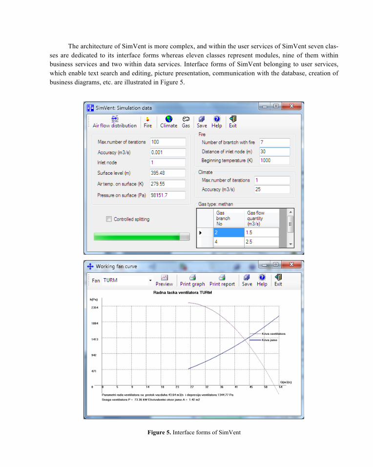
The architecture of SimVent is more complex, and within the user services of SimVent seven clas-ses are dedicated to its interface forms whereas eleven classes represent modules, nine of them within business services and two within data services. Interface forms of SimVent belonging to user services, which enable text search and editing, picture presentation, communication with the database, creation of business diagrams, etc. are illustrated in Figure 5.
Figure 5. Interface forms of SimVent
Nine interactively connected classes were identified within SimVent business services: three clas-ses belong to C# application modules, two of them are related to GA, and the remaining four pertain to the SimVent core simulation model composed of the following simulation blocks:
• air flow and pressure distribution in the ventilation network,
• climate conditions in mine workings,
• temperature and heat pressure in fire incidence conditions, and
• gas distribution in the ventilation network.
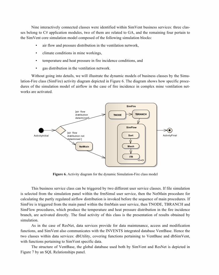
Without going into details, we will illustrate the dynamic models of business classes by the Simu-lation-Fire class (SimFire) activity diagram depicted in Figure 6. The diagram shows how specific proce-dures of the simulation model of airflow in the case of fire incidence in complex mine ventilation net-works are activated.
Figure 6. Activity diagram for the dynamic Simulation-Fire class model
This business service class can be triggered by two different user service classes. If file simulation is selected from the simulation panel within the frmSimul user service, then the NetMain procedure for calculating the partly regulated airflow distribution is invoked before the sequence of main procedures. If SimFire is triggered from the main panel within the frmMain user service, then TNODE, TBRANCH and SimFlow procedures, which produce the temperature and heat pressure distribution in the fire incidence branch, are activated directly. The final activity of this class is the presentation of results obtained by simulation.
As in the case of ResNet, data services provide for data maintenance, access and modification functions, and SimVent also communicates with the INVENTS integrated database VentBase. Hence the two classes within data services: dbUtility, covering functions pertaining to VentBase and dbSimVent, with functions pertaining to SimVent specific data.
The structure of VentBase, the global database used both by SimVent and ResNet is depicted in Figure 7 by an SQL Relationships panel.
act Class Model
SimFire
SimFlow
TNODE TBRANCH
Sort
Mesh
ITR
ActivityInitial ActivityFinal
NetMain
[air flowdistribution notdetermined ]
[air flowdistributiondetermined]
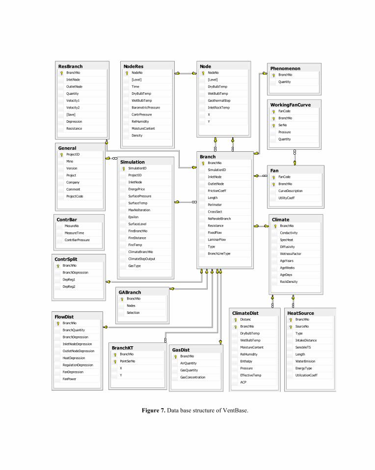
Figure 7. Data base structure of VentBase.
BranchBranchNo
SimulationID
InletNode
OutletNode
FrictionCoeff
Length
Perimeter
CrossSect
NoParalelBranch
Resistance
FixedFlow
LaminarFlow
Type
BranchLineType
ClimateBranchNo
Conductivity
SpecHeat
Diffusivity
WetnessFactor
AgeYears
AgeWeeks
AgeDays
RockDensity
ClimateDistDistanc
BranchNo
DryBulbTemp
WetBulbTemp
MoistureContent
RelHumidity
Enthalpy
Pressure
EffectiveTemp
ACP
ContrBarMesureNo
MeasureTime
ContrBarPressure
FanFanCode
BranchNo
CurveDescription
UtilityCoeff
FlowDistBranchNo
BranchQuantity
BranchDepression
InletNodeDepression
OutletNodeDepression
HeatDepression
RegulationDepression
FanDepression
FanPower
BranchKTBranchNo
PointSerNo
X
Y
GeneralProjectID
Mine
Version
Project
Company
Comment
ProjectCode
SimulationSimulationID
ProjectID
InletNode
EnergyPrice
SurfacePressure
SurfaceTemp
MaxNoIteration
Epsilon
SurfaceLevel
FireBranchNo
FireDistance
FireTemp
ClimateBranchNo
ClimateStepOutput
GasType
GasDistBranchNo
AirQuantity
GasQuantity
GasConcentration
HeatSourceBranchNo
SourceNo
Type
IntakeDistance
SensbileTS
Length
WaterEmision
EnergyType
UtilizationCoeff
ContrSplitBranchNo
BranchDepression
DepReg1
DepReg2
NodeNodeNo
[Level]
DryBulbTemp
WetBulbTemp
GeothermalStep
InletRockTemp
X
Y
PhenomenonBranchNo
Quantity
ResBranchBranchNo
InletNode
OutletNode
Quantity
Velocity1
Velocity2
[Save]
Depression
Resistance
WorkingFanCurveFanCode
BranchNo
SerNo
Pressure
Quantity
NodeResNodeNo
[Level]
Time
DryBulbTemp
WetBulbTemp
BarometricPressure
ContrPressure
RelHumidity
MoistureContent
Density
GABranchBranchNo
Nodes
Selection
Although the initial database was developed using the MS Access relational database management system, given the complexity of the global model of INVENTS data structure, which had to take into account all relevant parameters of complex mine ventilation networks, the database was later migrated to the MS SQL Server. This system offers both procedures for data manipulation and safe data archiving for complex data models. The use of SQL, a standard query language for data manipulation, provides for flexibility in connecting INVENTS to different environments.
The INVENTS knowledge based component VENTEX was initially developed as a symbolic up-grade of the SimVent numerical package, using basically the frames paradigm for knowledge representa-tion (Brachman and Levesque, 2004). It has been designed to apply the mine ventilation expert’s knowledge for the analysis and evaluation of results obtained by SimVent simulation routines. Subse-quently both components were integrated within INVENTS.
The SimVent and VENTEX components couple symbolic and numerical methods within IN-VENTS (Kowalik, 1986). To implement such a solution a number of complex problems had to be solved in order to secure efficient communication between the symbolic and the numerical part. This was achieved by a separation of processes within this coupled subsystem into independent modules, and by a strict definition of the information interchange protocol, namely the communication between the two components, which was reduced to the lowest possible degree. Communication between the components is permitted only through previously defined external links, whereas the implementation details remain “hidden” within the component itself. The coupling was successfully realized in INVENTS by using the object as the modular unit of the system within a modified object-oriented approach. In this approach objects consist of attributes (structures representing their internal data), methods (procedural/numerical components), and rules (declarative/symbolic components). The modified OOA approach was thus used for building the model of a strategy for evaluating the solution of the obtained mine ventilation system design.
The object/attribute paradigm can be successfully implemented by its mapping into the frame/slot paradigm (Schalkoff, 2009). Namely, the way characteristics of an object are represented by its attributes is analogous to the way frame characteristics are represented by its slots. If an object is represented by a frame, then slot values describe attributes, but also the relations of the frame to other frames/objects with-in the system. Such an implementation of the object-oriented approach by a system of frames provides for a successful decomposition of the proposed ventilation system evaluation strategy. Implementation of the knowledge base using this formalism alleviates both the coordination of knowledge within the knowledge base and the communication between the symbolic and the numerical component.
The knowledge based component of INVENTS was initially developed using an expert systems shell, the KAPPA-PC applications development system, which operated under MS Windows and, akin to other expert system shells, provided a wide range of tools for constructing and using expert system ap-plications (Giarratano and Riley, 2004). However, as the development and maintenance of KAPPA-PC has been discontinued, an in-house knowledge-based environment (KBE) has been developed along the same lines. Similar to KAPPA-PC, the environment provides for a representation of domain components by objects, which pertain either to classes or to their instances. The classes and instances within a specific system implemented using the KBE can be viewed by means of the KBE object browser (Figure 8). Ob-jects, that is, classes and instances are connected within this browser by links representing relationships between objects, which thus form a hierarchical structure. Such an approach enabled an easy mapping of
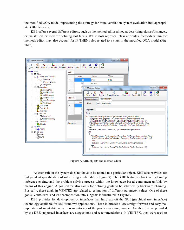
the modified OOA model representing the strategy for mine ventilation system evaluation into appropri-ate KBE elements.
KBE offers several different editors, such as the method editor aimed at describing classes/instances, or the slot editor used for defining slot facets. While slots represent class attributes, methods within the methods editor may also account for IF-THEN rules related to a class in the modified OOA model (Fig-ure 8).
Figure 8. KBE objects and method editor
As each rule in the system does not have to be related to a particular object, KBE also provides for independent specification of rules using a rule editor (Figure 9). The KBE features a backward chaining inference engine, and the problem-solving process within the knowledge based component unfolds by means of this engine. A goal editor also exists for defining goals to be satisfied by backward chaining. Basically, these goals in VENTEX are related to estimation of different parameter values. One of these goals, VentMreza, and its decomposition into subgoals is illustrated in Figure 9.
KBE provides for development of interfaces that fully exploit the GUI (graphical user interface) technology available for MS Windows applications. These interfaces allow straightforward and easy ma-nipulation of input data as well as monitoring of the problem-solving process. Another feature provided by the KBE supported interfaces are suggestions and recommendations. In VENTEX, they were used to
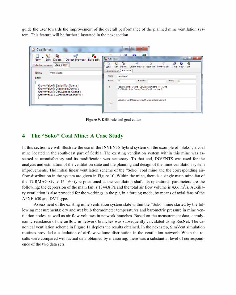
guide the user towards the improvement of the overall performance of the planned mine ventilation sys-tem. This feature will be further illustrated in the next section.
Figure 9. KBE rule and goal editor
4 The “Soko” Coal Mine: A Case Study
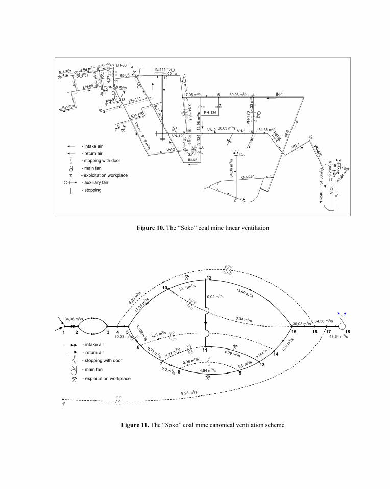
In this section we will illustrate the use of the INVENTS hybrid system on the example of “Soko”, a coal mine located in the south-east part of Serbia. The existing ventilation system within this mine was as-sessed as unsatisfactory and its modification was necessary. To that end, INVENTS was used for the analysis and estimation of the ventilation state and the planning and design of the mine ventilation system improvements. The initial linear ventilation scheme of the “Soko” coal mine and the corresponding air-flow distribution in the system are given in Figure 10. Within the mine, there is a single main mine fan of the TURMAG Gvhv 15-160 type positioned at the ventilation shaft. Its operational parameters are the following: the depression of the main fan is 1344.8 Pa and the total air flow volume is 43.6 m3/s. Auxilia-ry ventilation is also provided for the workings in the pit, in a forcing mode, by means of axial fans of the APXE-630 and DVT type.
Assessment of the existing mine ventilation system state within the “Soko” mine started by the fol-lowing measurements: dry and wet bulb thermometer temperatures and barometric pressure in mine ven-tilation nodes, as well as air flow volumes in network branches. Based on the measurement data, aerody-namic resistance of the airflow in network branches was subsequently calculated using ResNet. The ca-nonical ventilation scheme in Figure 11 depicts the results obtained. In the next step, SimVent simulation routines provided a calculation of airflow volume distribution in the ventilation network. When the re-sults were compared with actual data obtained by measuring, there was a substantial level of correspond-ence of the two data sets.
1
16
2
317
1918
4510
12
614
15
7
11
13
9
8
V.O
.
PH
-240
VN-8VN-1
I.O.
OH-240
IN-5PSES
IN-1
PH
-170PH-136
VH-1VN-2VN-129
VH
-135
VV-2
IN-66
IN-1
24
VN-85
EH-120
EH-111PH-91
EH-89
EH-98z
EH-80zEH-80i
IN-85IN-111
34,3
6 m
3 /s
30,03 m3/s
4,33
m3 /
s
12,9
8 m
3 /s
3,21m3/s
17,05 m3/s
9,77 m3/s
13,71 m3/s
3,34 m3/s
5,5 m3/s
4,27
m3 /
s
4,54 m3/s
0,96 m3/s 5,8 m3/s
9,79 m3/s
13 m
3 /s
30,03 m3/s 34,36 m3/s
9,28
m3 /
s
43,64
m3 /s
34,3
6m3 /
s
- intake air- return air- stopping with door- main fan
- auxiliary fan- exploitation workplace
- stopping
Figure 10. The “Soko” coal mine linear ventilation
Figure 11. The “Soko” coal mine canonical ventilation scheme
1 2 3 4 5
6
7
8
11
9
13
14
15 16 17 18
10
1'
12
34,36 m3/s
4,33 m
3 /s
30,03 m3/s
17,05
m3 /s
12,98 m3/s
9,77 m 3/s
3,21 m3 /s
4,27 m3 /s
5,5 m 3/s
0,96 m3 /s
4,54 m3/s5,5 m
3 /s9,79 m
3 /s 13,0
m3 /s
9,28 m3/s
30,03 m3/s34,36 m3/s
43,64 m3/s
3,34 m3/s
13,71m3 /s
- intake air
- return air
0,02 m3/s
4,29 m 3/s
13,69 m 3/s
- stopping with door
- main fan
- exploitation workplace
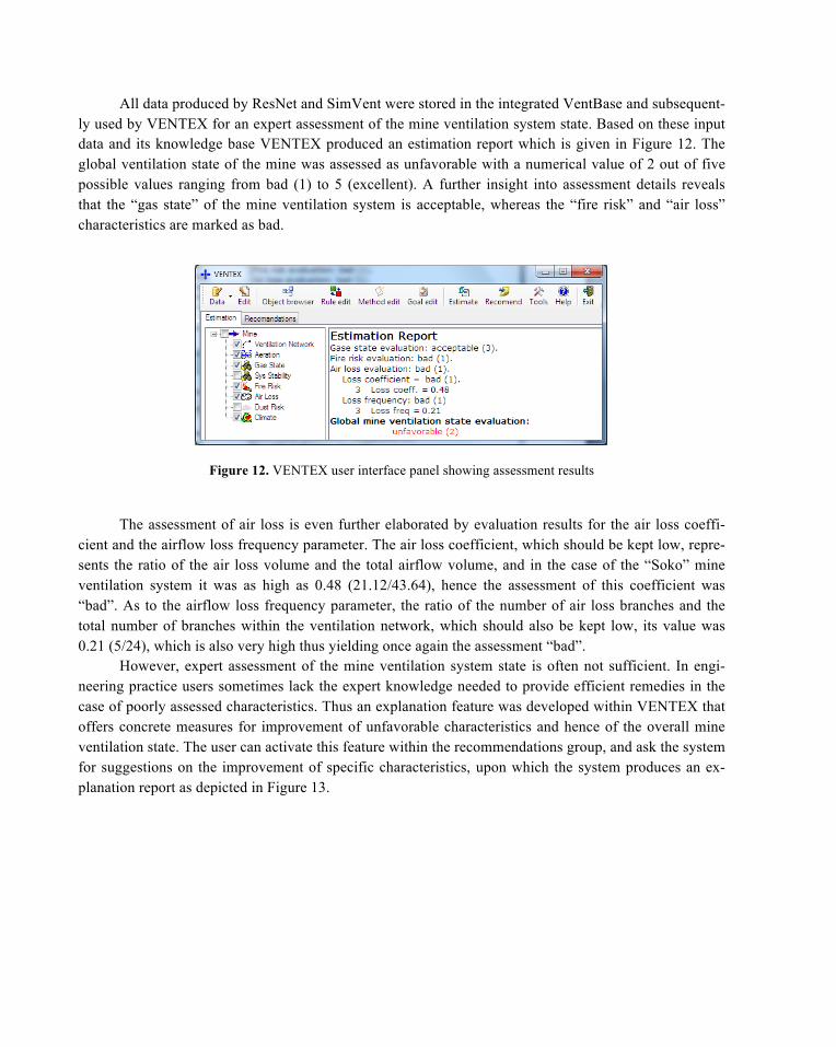
All data produced by ResNet and SimVent were stored in the integrated VentBase and subsequent-ly used by VENTEX for an expert assessment of the mine ventilation system state. Based on these input data and its knowledge base VENTEX produced an estimation report which is given in Figure 12. The global ventilation state of the mine was assessed as unfavorable with a numerical value of 2 out of five possible values ranging from bad (1) to 5 (excellent). A further insight into assessment details reveals that the “gas state” of the mine ventilation system is acceptable, whereas the “fire risk” and “air loss” characteristics are marked as bad.
Figure 12. VENTEX user interface panel showing assessment results
The assessment of air loss is even further elaborated by evaluation results for the air loss coeffi-cient and the airflow loss frequency parameter. The air loss coefficient, which should be kept low, repre-sents the ratio of the air loss volume and the total airflow volume, and in the case of the “Soko” mine ventilation system it was as high as 0.48 (21.12/43.64), hence the assessment of this coefficient was “bad”. As to the airflow loss frequency parameter, the ratio of the number of air loss branches and the total number of branches within the ventilation network, which should also be kept low, its value was 0.21 (5/24), which is also very high thus yielding once again the assessment “bad”.
However, expert assessment of the mine ventilation system state is often not sufficient. In engi-neering practice users sometimes lack the expert knowledge needed to provide efficient remedies in the case of poorly assessed characteristics. Thus an explanation feature was developed within VENTEX that offers concrete measures for improvement of unfavorable characteristics and hence of the overall mine ventilation state. The user can activate this feature within the recommendations group, and ask the system for suggestions on the improvement of specific characteristics, upon which the system produces an ex-planation report as depicted in Figure 13.
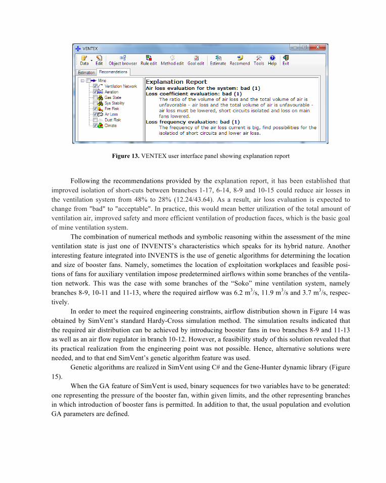
Figure 13. VENTEX user interface panel showing explanation report
Following the recommendations provided by the explanation report, it has been established that improved isolation of short-cuts between branches 1-17, 6-14, 8-9 and 10-15 could reduce air losses in the ventilation system from 48% to 28% (12.24/43.64). As a result, air loss evaluation is expected to change from "bad" to "acceptable". In practice, this would mean better utilization of the total amount of ventilation air, improved safety and more efficient ventilation of production faces, which is the basic goal of mine ventilation system.
The combination of numerical methods and symbolic reasoning within the assessment of the mine ventilation state is just one of INVENTS’s characteristics which speaks for its hybrid nature. Another interesting feature integrated into INVENTS is the use of genetic algorithms for determining the location and size of booster fans. Namely, sometimes the location of exploitation workplaces and feasible posi-tions of fans for auxiliary ventilation impose predetermined airflows within some branches of the ventila-tion network. This was the case with some branches of the “Soko” mine ventilation system, namely branches 8-9, 10-11 and 11-13, where the required airflow was 6.2 m3/s, 11.9 m3/s and 3.7 m3/s, respec-tively.
In order to meet the required engineering constraints, airflow distribution shown in Figure 14 was obtained by SimVent’s standard Hardy-Cross simulation method. The simulation results indicated that the required air distribution can be achieved by introducing booster fans in two branches 8-9 and 11-13 as well as an air flow regulator in branch 10-12. However, a feasibility study of this solution revealed that its practical realization from the engineering point was not possible. Hence, alternative solutions were needed, and to that end SimVent’s genetic algorithm feature was used.
Genetic algorithms are realized in SimVent using C# and the Gene-Hunter dynamic library (Figure 15).
When the GA feature of SimVent is used, binary sequences for two variables have to be generated: one representing the pressure of the booster fan, within given limits, and the other representing branches in which introduction of booster fans is permitted. In addition to that, the usual population and evolution GA parameters are defined.
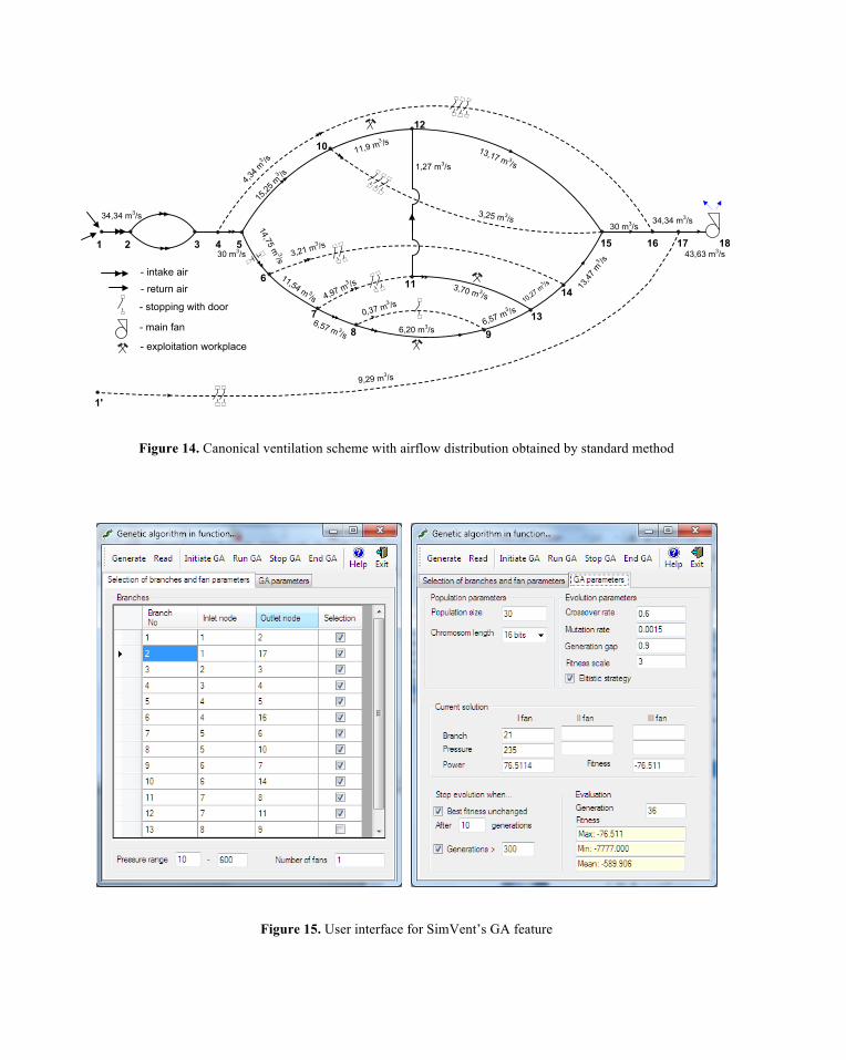
Figure 14. Canonical ventilation scheme with airflow distribution obtained by standard method
Figure 15. User interface for SimVent’s GA feature
1 2 3 4 5
6
7
8
11
9
13
14
15 16 17 18
10
1'
12
34,34 m3/s
4,34 m
3 /s
30 m3/s
15,25
m3 /s
14,75 m3/s
11,54 m 3/s
3,21 m3 /s
4,97 m3 /s
6,57 m 3/s
0,37 m3 /s
6,20 m3/s6,57 m
3 /s10,27 m
3 /s 13,47
m3 /s
9,29 m3/s
30 m3/s34,34 m3/s
43,63 m3/s
3,25 m3/s
11,9 m3 /s
- intake air
- return air
1,27 m3/s
3,70 m 3/s
13,17 m 3/s
- stopping with door
- main fan
- exploitation workplace

The fitness function is the total power consumption of the ventilation system, which is basically the sum of the power of the main and booster fans for a given solution, calculated by SimVent’s simula-tion feature based on the Hardy-Cross method. In the optimal solution the power consumption should be as low as possible, which means that the fitness function should be minimized. In the simulation process, variation of aerodynamic resistance is permitted in branches with predetermined airflows, which provides for a balance of airflow within the remaining branches. When a positive value of additional resistance is detected, an airflow regulator is needed. When it is negative, then a booster fan is required. Hence, the airflow distribution in the ventilation network needs to satisfy the following constraints:
• booster fans are not allowed in branches with predetermined airflows, and
• recirculation of air is not allowed within loss paths.
The possibility that GA will select a solution that violates these constraints in the reproduction process is extremely small, as the fitness for such solutions would be very high.
Branch No. Inlet-outlet Node R (Ns2/m8) Q (m3/s) P (Pa) NVP (Pa) Pr (Pa) Pbf (Pa)
1 1-2 0.0085 34.54 10.14 179.86 2 1-17 14.7999 9.23 1260.42 -0.33 3 2-3 0.1296 34.54 154.58 0 4 3-4 0.3281 34.54 391.33 80.95 5 4-5 0.0575 30.28 52.72 39.20 6 4-16 34.9931 4.26 633.69 -0.02 7 5-6 0.0685 15.13 15.68 1.50 8 5-10 0.0233 15.15 5.35 13.53 9 6-7 0.4130 12.03 59.75 62.5
10 6-14 44.5837 3.10 429.02 -1.14 11 7-8 0.2365 7.52 13.37 0 12 7-11 1.9649 4.51 39.96 0 13 8-9 3.3602 6.20 129.17 -10.26 0.50 14 8-9 74.6793 1.32 129.67 -10-26 15 9-13 0.5498 7.52 31.07 -2.27 16 10-12 0.4218 11.9 59.73 7.73 49.67 17 10-15 42.3614 3.25 447.63 -13.12 18 11-12 0.0001 0.81 0 -42.10 19 11-13 3.1067 3.70 42.53 -12.57 91.58 20 12-15 2.0944 12.71 338.33 -20.76 21 13-14 3.4245 11.22 430.93 -50.38 235 22 14-15 0.0402 14.32 8.24 0 23 15-16 0,1400 30.28 128.37 -39.24 24 16-17 0.0614 34.54 73.23 -258.56 25 17-18 0.0362 43.76 69.33 0
Table 1. The air distribution obtained by GA
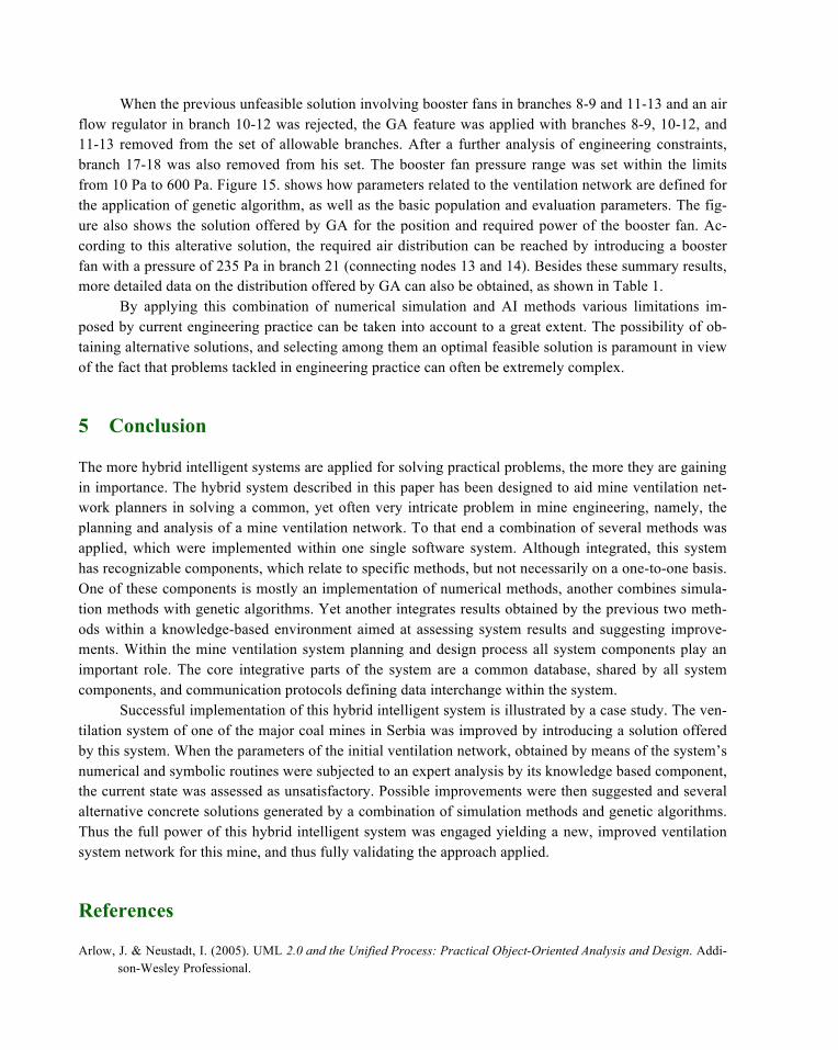
When the previous unfeasible solution involving booster fans in branches 8-9 and 11-13 and an air flow regulator in branch 10-12 was rejected, the GA feature was applied with branches 8-9, 10-12, and 11-13 removed from the set of allowable branches. After a further analysis of engineering constraints, branch 17-18 was also removed from his set. The booster fan pressure range was set within the limits from 10 Pa to 600 Pa. Figure 15. shows how parameters related to the ventilation network are defined for the application of genetic algorithm, as well as the basic population and evaluation parameters. The fig-ure also shows the solution offered by GA for the position and required power of the booster fan. Ac-cording to this alterative solution, the required air distribution can be reached by introducing a booster fan with a pressure of 235 Pa in branch 21 (connecting nodes 13 and 14). Besides these summary results, more detailed data on the distribution offered by GA can also be obtained, as shown in Table 1.
By applying this combination of numerical simulation and AI methods various limitations im-posed by current engineering practice can be taken into account to a great extent. The possibility of ob-taining alternative solutions, and selecting among them an optimal feasible solution is paramount in view of the fact that problems tackled in engineering practice can often be extremely complex.
5 Conclusion
The more hybrid intelligent systems are applied for solving practical problems, the more they are gaining in importance. The hybrid system described in this paper has been designed to aid mine ventilation net-work planners in solving a common, yet often very intricate problem in mine engineering, namely, the planning and analysis of a mine ventilation network. To that end a combination of several methods was applied, which were implemented within one single software system. Although integrated, this system has recognizable components, which relate to specific methods, but not necessarily on a one-to-one basis. One of these components is mostly an implementation of numerical methods, another combines simula-tion methods with genetic algorithms. Yet another integrates results obtained by the previous two meth-ods within a knowledge-based environment aimed at assessing system results and suggesting improve-ments. Within the mine ventilation system planning and design process all system components play an important role. The core integrative parts of the system are a common database, shared by all system components, and communication protocols defining data interchange within the system.
Successful implementation of this hybrid intelligent system is illustrated by a case study. The ven-tilation system of one of the major coal mines in Serbia was improved by introducing a solution offered by this system. When the parameters of the initial ventilation network, obtained by means of the system’s numerical and symbolic routines were subjected to an expert analysis by its knowledge based component, the current state was assessed as unsatisfactory. Possible improvements were then suggested and several alternative concrete solutions generated by a combination of simulation methods and genetic algorithms. Thus the full power of this hybrid intelligent system was engaged yielding a new, improved ventilation system network for this mine, and thus fully validating the approach applied.
References
Arlow, J. & Neustadt, I. (2005). UML 2.0 and the Unified Process: Practical Object-Oriented Analysis and Design. Addi-son-Wesley Professional.
Back, T, Fogel, D.B & Michalewicz, Z. (2000) Evolutionary Computation 1: Advanced Algorithms and Operators. Insti-tute of Physics Publishing, Bristol-Philadelphia.
Brachman R., Levesque, H. (2004). Knowledge Representation and Reasoning. The Morgan Kaufmann Series in Artificial Intelligence.
Giarratano J. C., Riley G. D. (2004) Expert Systems: Principles and Programming, Fourth Edition, Course Technology.
Hartman, H.L., Mutmansky, J.M., Ramani, R.V. & Wang Y.J. (1997) Mine Ventilation and Air Conditioning. John Wiley & Sons, Inc.
Jones, M. T. (2008). Artificial Intelligence: A Systems Approach, Jones & Bartlett Learning.
Kowalik, J.S., (ed.). (1986). Coupling Symbolic and Numerical Computing in Expert Systems. North-Holland, Amsterdam.
Lilić, N, Obradović, I & Stanković, R. (2002). A Knowledge-Based Approach to Mine Ventilation Planning. In Yugoslav Mining Practice, Mineral Resources Engineering, Vol. 11, No 4 (pp. 361-382).
Lilić, N., Obradović, I. & Stanković, R., (1997a). Ventex: An Expert System for Mine Ventilation Systems Analysis. In Mining Technology, Vol. 79, No 915, (pp. 295-302).
Lilić, N., Stanković, R. & Obradović, I. (1997b). Mine ventilation system planning using genetic algorithms. In Proceed-ings of the Sixth International Symposium on Mine Planning and Equipment Selection .A.A.Balkema, Roter-dam/Brookfield, (pp.691-697).
McPherson, M.J. (1993). Subsurface Ventilation and Environmental Engineering. Chapman & Hall.
Oral, M.K. & Durucan,S. (1993). An Integrated Environment Simulation System for Mine Ventilation Management. In XXIII International Symposium APCOM, Montreal, Vol.II, (pp. 327-334).
Ramani, R.V., Prasad, K.V.K. & Swaminathan, M. (1990). Implementation of KBS for Mine Ventilation Planning and Design. In XXII International Symposium APCOM , Berlin, Vol.II, (pp. 329-352).
Schalkoff R. J. (2009). Intelligent Systems: Principles, Paradigms and Pragmatics, Jones & Bartlett Publishers.
Yang, Z.Y., Lowndes I.S. & Denby B. (1998a). Genetic Algorithm Optimization of Large U.K. Coal Mine Ventilation Network. In Proceedings of 8th US Mine Ventilation Symposium, (pp. 625-632).
Yang, Z.Y., Lowndes I.S. & Denby B. (1998b). Application of genetic algorithms to the optimization of large mine venti-lation networks. In Trans. Instn Min. Metall., Sect. A: Min. industry, 107, (pp. A109-A116).