TechXcite Wireless TVRemote Act4
11
Wireless Transmission: Your TV Remote Pilot Module Spring 2008 (Updated 2/7/08) 35 Activity 4: IR Music Transmitter Time Required: 45 minutes Materials List Group Size: 2 Each pair needs: One each of: • One Activity 4 bag containing: o 10 Ω Resistor (brown, black, black) o 4.7 kΩ Resistor (yellow, violet, red) o 220 Ω Resistor (red, red brown) o 1 kΩ Resistor (brown, black, red) o 100 Ω Resistor (brown, black, brown) o IR LED o Transistor (2N3904) o 50 kΩ Potentiometer • These items are provided in a separate bag, but will be placed back in Activity 4 bag after activity for use in subsequent years: o 4.7 μF Electrolytic Capacitor o Earphone Plug with 6’ Cable o Seven 2” Jumper Wires • 9 V Battery • Battery Snap (in bag with breadboard) • Breadboard To share between every two groups: • Multimeter • Pliers Student Handouts • Activity 4: IR Music Transmitter Learning Objectives After this activity, students should be able to: • Build an IR Music Transmitter circuit • Identify and use a transistor • Transmit music using infrared light Introduction Last time we met, you built a timer circuit using a 555 timer to transmit an infrared signal that caused the receiver to make various tones depending on the position of the potentiometer. This time you will build a different kind of infrared transmitter. This one will be a music transmitter. It will take the output of a music player and cause the infrared LED to get brighter and dimmer, transmitting the music. The infrared receiver circuit from activity 2 will receive the infrared signal and play the music out of the
-
Upload
ashique-raeen -
Category
Documents
-
view
223 -
download
0
Transcript of TechXcite Wireless TVRemote Act4

8/3/2019 TechXcite Wireless TVRemote Act4
http://slidepdf.com/reader/full/techxcite-wireless-tvremote-act4 1/11
Wireless Transmission: Your TV Remote
Pilot Module Spring 2008 (Updated 2/7/08) 35
Activity 4: IR Music Transmitter
Time Required: 45 minutes
Materials ListGroup Size: 2
Each pair needs:One each of:
• One Activity 4 bag containing:
o 10 Ω Resistor (brown, black, black)
o 4.7 kΩ Resistor (yellow, violet, red)
o 220 Ω Resistor (red, red brown)
o 1 kΩ Resistor (brown, black, red)
o 100 Ω Resistor (brown, black, brown)o IR LEDo Transistor (2N3904)
o
50 kΩ Potentiometer• These items are provided in a separate bag, but will be placed back in Activity4 bag after activity for use in subsequent years:
o 4.7 μF Electrolytic Capacitoro Earphone Plug with 6’ Cableo Seven 2” Jumper Wires
• 9 V Battery
• Battery Snap (in bag with breadboard)
• BreadboardTo share between every two groups:
• Multimeter • Pliers
Student Handouts
• Activity 4: IR Music Transmitter
Learning ObjectivesAfter this activity, students should be able to:
• Build an IR Music Transmitter circuit
• Identify and use a transistor
• Transmit music using infrared light
IntroductionLast time we met, you built a timer circuit using a 555 timer to transmit an infrared signalthat caused the receiver to make various tones depending on the position of thepotentiometer. This time you will build a different kind of infrared transmitter. This onewill be a music transmitter. It will take the output of a music player and cause theinfrared LED to get brighter and dimmer, transmitting the music. The infrared receivercircuit from activity 2 will receive the infrared signal and play the music out of the
8/3/2019 TechXcite Wireless TVRemote Act4
http://slidepdf.com/reader/full/techxcite-wireless-tvremote-act4 2/11
Wireless Transmission: Your TV Remote
Pilot Module Spring 2008 (Updated 2/7/08) 36
speaker. The signal from any music player can be “jacked in” to the input of thetransmitter.
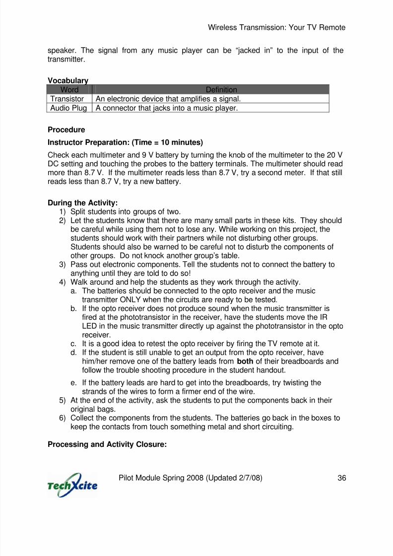
VocabularyWord Definition
Transistor An electronic device that amplifies a signal.Audio Plug A connector that jacks into a music player.
Procedure
Instructor Preparation: (Time = 10 minutes)
Check each multimeter and 9 V battery by turning the knob of the multimeter to the 20 VDC setting and touching the probes to the battery terminals. The multimeter should readmore than 8.7 V. If the multimeter reads less than 8.7 V, try a second meter. If that stillreads less than 8.7 V, try a new battery.
During the Activity:1) Split students into groups of two.2) Let the students know that there are many small parts in these kits. They should
be careful while using them not to lose any. While working on this project, thestudents should work with their partners while not disturbing other groups.Students should also be warned to be careful not to disturb the components ofother groups. Do not knock another group’s table.
3) Pass out electronic components. Tell the students not to connect the battery toanything until they are told to do so!
4) Walk around and help the students as they work through the activity.
a. The batteries should be connected to the opto receiver and the musictransmitter ONLY when the circuits are ready to be tested.
b. If the opto receiver does not produce sound when the music transmitter isfired at the phototransistor in the receiver, have the students move the IRLED in the music transmitter directly up against the phototransistor in the optoreceiver.
c. It is a good idea to retest the opto receiver by firing the TV remote at it.d. If the student is still unable to get an output from the opto receiver, have
him/her remove one of the battery leads from both of their breadboards andfollow the trouble shooting procedure in the student handout.
e. If the battery leads are hard to get into the breadboards, try twisting the
strands of the wires to form a firmer end of the wire.5) At the end of the activity, ask the students to put the components back in their
original bags.6) Collect the components from the students. The batteries go back in the boxes to
keep the contacts from touch something metal and short circuiting.
Processing and Activity Closure:

8/3/2019 TechXcite Wireless TVRemote Act4
http://slidepdf.com/reader/full/techxcite-wireless-tvremote-act4 3/11
Wireless Transmission: Your TV Remote
Pilot Module Spring 2008 (Updated 2/7/08) 37
[After most of the student groups have finished writing their descriptions of the circuit inthe assessment, but before they clean up, it is important to go over the circuit.]How does the sound come out of your music players? The music comes out of theplayer as an electrical signal. This is generally turned into sound by small speakers inyour headphones that convert electrical signals into sound.
In your worksheets, you were asked to describe how the music gets from your musicplayer to the speaker on your receiver circuit. What did you write down for this?
[You can have one person go through the entire process or after one person hasexplained the transmission component, you can ask somebody else to continue. Letthem say what they think happens all the way through. Whether it is right or wrong, askthe other students if they agree with this. Then, if it’s right, you can confirm it for them.If there are portions that are right, confirm those sections for the class and tell them theparts that are not quite right. If you’re not sure if something they say is right or wrong,
just tell them you don’t know but you will ask somebody. You can ask on the TechXcite
forum for the “Your TV Remote” module online at www.techxcite.pratt.duke.edu. If noneof it is correct you can provide the entire explanation below.]
1) The electrical signal from your music player is converted into an invisible infraredlight signal by the infrared light emitting diode (IR LED) in the transmitter circuit.If we wanted to transmit this over a longer distance, we would need to use abrighter IR LED or we would have to focus the invisible light using a lens.
2) The invisible infrared light signal must hit the photo transistor in the receiver.3) The photo transistor in the receiver converts this invisible infrared light signal into
an electrical signal.4) Then, the amplifier in the receiver circuit takes this electrical signal and makes it
larger using energy from the battery.5) Finally, this larger electrical signal drives the speaker which turns electrical
energy into sound energy.
Additional Resources
Chaney Electronics – BBK-3 44 in 1 Communications and Opto Lab Kithttp://www.kitsuse.net
For more information about how speakers work:http://electronics.howstuffworks.com/speaker.htm
Assessment
1) Please indicate the percentage of groups whose circuits were able to transmitmusic to the receiver. This will be used to assess whether or not students wereable to build the circuit correctly. It will also be used to assess whether or not thestudents learned that music can be transmitted via infrared light. Finally, it willalso be used to assess the activity itself to determine how well it works.

8/3/2019 TechXcite Wireless TVRemote Act4
http://slidepdf.com/reader/full/techxcite-wireless-tvremote-act4 4/11
Wireless Transmission: Your TV Remote
Pilot Module Spring 2008 (Updated 2/7/08) 38
2) Collect or copy page 44 of the student handout. Their descriptions of how thesound goes from the music player to the speaker will be used to assess theirbasic understanding of the circuit. We will be looking for the following:
a. Does the student state that the music comes out of the music player as anelectrical signal?
b. Does the student state that the IR LED gets brighter and dimmer to createan invisible light (infrared) signal that carries the sound from one circuit tothe other?
c. Does the student state that the photo transistor turns the invisible light(infrared) signal into an electrical signal?
d. Does the student state that the amplifier on the receiver takes thatelectrical signal and makes it stronger so we can hear it when it comes outof the speaker?
e. Does the student recognize that the speaker takes the electrical signaland turns it into sound that we can hear?
References
Chaney Electronics, 44 in 1 Communications and Opto Lab Manual, 1997.
Authors: Dr. Gary A. Ybarra, Dr. Paul A. Klenk
Contributors: Dr. Martin Brooke, Heather Wake, Xin Cai, Arnak Aleksanyan,Department of Electrical and Computer Engineering, Duke University
Copyright: Engineering K-Ph.D. Program, Pratt School of Engineering, Duke University

8/3/2019 TechXcite Wireless TVRemote Act4
http://slidepdf.com/reader/full/techxcite-wireless-tvremote-act4 5/11
Wireless Transmission: Your TV Remote
Pilot Module Spring 2008 (Updated 2/7/08) 39
Activity 4: IR Music Transmitter Student Handout
Name: ________________________
Date: __________
In this activity you will build an infrared (IR) opto music transmitter. The signal from anymusic player can be “jacked in” to the input of the transmitter. The sound signalmodulates the intensity of IR light, which carries the sound to the opto receiver. Theopto receiver then amplifies the audio signal and the sound comes out of the speaker.
Parts List
R1: 10 Ω Resistor (brown, black, black)
R2: 4.7 kΩ Resistor (yellow, violet, red)
R3: 220 Ω Resistor (red, red brown)
R4: 1 kΩ Resistor (brown, black, red)
R5: 100 Ω Resistor (brown, black, brown)
P1: 50 kΩ PotentiometerC1: 4.7 μF Electrolytic CapacitorL1: IR LEDQ1: Transistor (2N3904)Earphone Plug with 6’ Cable9 V BatteryBattery SnapBreadboard2” Jumper Wires
You know how to identify the resistors from Activity 1 by using the resistor color code.You know how to identify the pot, the electrolytic capacitor and the IR LED fromActivities 2 and 3.
The 2N3904 transistor has a black body with a flat front and three leadscoming out of the bottom of the body.
The earphone plug is a standard 1/8th inch mini plug that fits
most portable music players. The other end of the cable has twowires that can be inserted into a breadboard.

8/3/2019 TechXcite Wireless TVRemote Act4
http://slidepdf.com/reader/full/techxcite-wireless-tvremote-act4 6/11
Wireless Transmission: Your TV Remote
Pilot Module Spring 2008 (Updated 2/7/08) 40
Overview
The opto transmitter circuit you will build has the following schematic.
The black dots emphasize that a physical connection is made. The wire that goes fromthe middle lead of the pot (P1) to the middle lead of the transistor (Q1) does not connect to the wire between R3 and P1 even though the wires cross because there isno black dot at the cross point!
As you build the circuit on yourbreadboard, you should lookback at the schematicfrequently to relate theschematic drawing to yourbreadboard circuit.
When you have built the entireIR music transmitter circuit, itshould look like the picture tothe left.

8/3/2019 TechXcite Wireless TVRemote Act4
http://slidepdf.com/reader/full/techxcite-wireless-tvremote-act4 7/11
Wireless Transmission: Your TV Remote
Pilot Module Spring 2008 (Updated 2/7/08) 41
Building the IR Music Transmitter Circuit
Rotate your breadboard so thatthe top of the breadboard is toyour right and the +9 V red power
supply rail is directly in front ofyou.
The first component to place onyour breadboard is Q1, the2N3904 Transistor. Spread theleads out if needed. With the flatside of the transistor body facingyou, insert the left lead of Q1 inhole F24, the middle lead in hole
F22, and the right lead in hold F20. Connect R5 (100 Ω brown, black, brown) between
the right lead of the transistor and the +9 V power supply rail.
Connect a wire jumper from holeH24 to H30.
Connect the IR LED from F30 toE30 with the longer lead (+) inF30 and the shorter lead (-) inE30. Connect a wire jumper fromA30 to ground (blue negativepower supply rail).
Compare your circuit on thebreadboard with the schematic.
Connect R3 (220 Ω red, redbrown) between hole J26 and the+9 V power supply rail.
Connect a wire jumper from hole
F26 to hole E21.
Connect a wire jumper from holeH22 to hole H15.

8/3/2019 TechXcite Wireless TVRemote Act4
http://slidepdf.com/reader/full/techxcite-wireless-tvremote-act4 8/11
Wireless Transmission: Your TV Remote
Pilot Module Spring 2008 (Updated 2/7/08) 42
Connect wire jumpers asfollows:
F15 to E19
D17 to D14A5 to ground (neg. supply rail)
Connect R4 (1 kΩ brown,black, red) from A14 to gound.
Connect R2 (4.7 kΩ yellow,violet, red) from G15 to G10.
Connect C1 (4.7 μF Electrolytic Capacitor) from hole H10 to H5 making sure that the
negative lead is in hole H5.
Connect R1 (10 Ω brown, black, black) from hole F5 to hole C5. We are almost finished!
Insert the pot with the stempointing away from you withits lead in holes: A21, A19and A17.
Remember, when you insertthe pot in the breadboard,
make sure it is inserted allthe way down.
8/3/2019 TechXcite Wireless TVRemote Act4
http://slidepdf.com/reader/full/techxcite-wireless-tvremote-act4 9/11
Wireless Transmission: Your TV Remote
Pilot Module Spring 2008 (Updated 2/7/08) 43
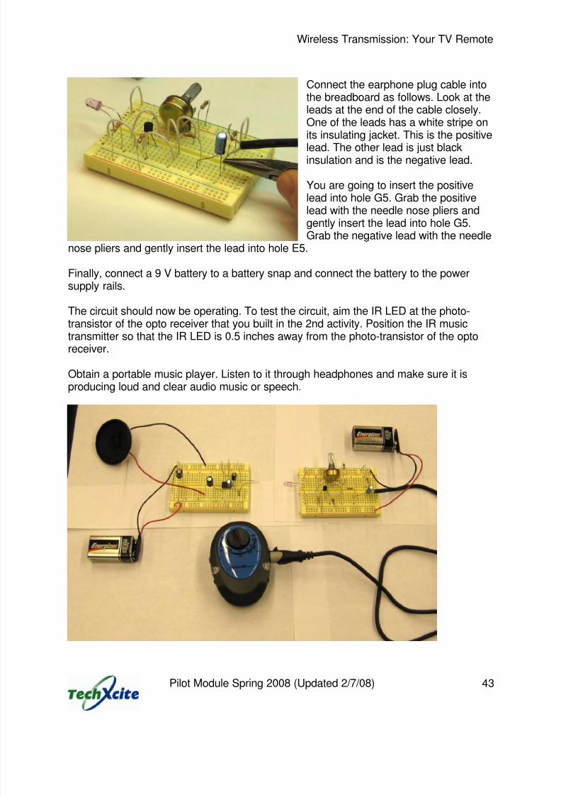
Connect the earphone plug cable intothe breadboard as follows. Look at theleads at the end of the cable closely.One of the leads has a white stripe on
its insulating jacket. This is the positivelead. The other lead is just blackinsulation and is the negative lead.
You are going to insert the positivelead into hole G5. Grab the positivelead with the needle nose pliers andgently insert the lead into hole G5.Grab the negative lead with the needle
nose pliers and gently insert the lead into hole E5.
Finally, connect a 9 V battery to a battery snap and connect the battery to the powersupply rails.
The circuit should now be operating. To test the circuit, aim the IR LED at the photo-transistor of the opto receiver that you built in the 2nd activity. Position the IR musictransmitter so that the IR LED is 0.5 inches away from the photo-transistor of the optoreceiver.
Obtain a portable music player. Listen to it through headphones and make sure it isproducing loud and clear audio music or speech.

8/3/2019 TechXcite Wireless TVRemote Act4
http://slidepdf.com/reader/full/techxcite-wireless-tvremote-act4 10/11
Wireless Transmission: Your TV Remote
Pilot Module Spring 2008 (Updated 2/7/08) 44
Connect the music player to your IR music transmitter by connecting the earphone plugto the headphone jack of your music player. Turn up the volume on your music player.Rotate the stem of the pot on your transmitter circuit. You should hear music coming outof the speaker in the receiver. If you do not hear any sound out of the speaker, you willneed to troubleshoot your IR music transmitter-receiver system.
If your circuit does not work, immediately disconnect one of the battery snapleads from the breadboard of BOTH the transmitter and the receiver.
Troubleshooting (Go through this process if your circuit fails to operate)
Troubleshooting is the process of figuring out why a circuit does not work.
1) The most common problem is a wiring error. Check your transmitter circuit tomake sure that every wire and component lead is going into the hole you think itshould go into.
2) The second most common error is a polarity mistake. Check the polarity of C1and the IR LED.3) Is the battery dead? Use the voltmeter to measure the voltage across the battery
terminals. Is it 9 V or higher? If not, replace the battery.The problem with the circuit must be one of the mistakes listed above. You must gothrough each step carefully until you find and correct the problem.
System Operation, Exploration and Description
Twist the pot stem in the music IR transmitter circuit until the sound produced by thespeaker is as clear as possible.
Explain how the sound goes from the music player to the speaker.
Answer:

8/3/2019 TechXcite Wireless TVRemote Act4
http://slidepdf.com/reader/full/techxcite-wireless-tvremote-act4 11/11
Wireless Transmission: Your TV Remote
Pilot Module Spring 2008 (Updated 2/7/08) 45
Disassembling the Circuit
Return the circuit components to their proper storage bags as instructed. Do not mixthe components from the receiver and the music transmitter.
For the Receiver from Activity 2:All of your small components from the receiver breadboard will go in the Activity 2 bagexcept the battery snap.
For the Music Transmitter from Activity 4:All of your small components from the transmitter breadboard will go in the Activity 4bag except the battery snap.
You will now disassemble both your transmitter and your receiver. Remove thepotentiometer, resistors, jumper wires, capacitors and IR LED. Care must be takenwhen removing an IC from the breadboard. The easiest way to do this is to use a pair of
needle nose pliers to extract the IC as shown in the figure below.
Grip the IC on the ends with theneedle nose pliers. Do notsqueeze the pliers too tightly, asthis can damage the IC.
Hold the breadboard down withyour other hand.
Carefully pull the IC direct out ofthe breadboard.
The idea is to avoid bending thepins of the IC.
The battery snap and breadboard from both circuits will go in a bag together. Returnboth batteries to your instructor.


![Weekly Tallahasseean. (Tallahassee, Florida) 1902-01-17 [p 4].ufdcimages.uflib.ufl.edu/UF/00/08/09/51/00080/00644.pdf · aCT4-ohn W SORE The RUrTlamaB TALLAHASSEE conscientious-officer](https://static.fdocuments.us/doc/165x107/5f0dd47a7e708231d43c4bfd/weekly-tallahasseean-tallahassee-florida-1902-01-17-p-4-act4-ohn-w-sore-the.jpg)