Sequential circuits in digital logic design
23
SEQUENTIAL CIRCUITS 12/11/2014 1
-
Upload
nallapati-anindra -
Category
Engineering
-
view
527 -
download
3
Transcript of Sequential circuits in digital logic design
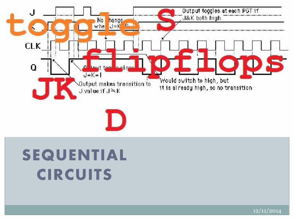
SEQUENTIAL
CIRCUITS
12/11/2014
1
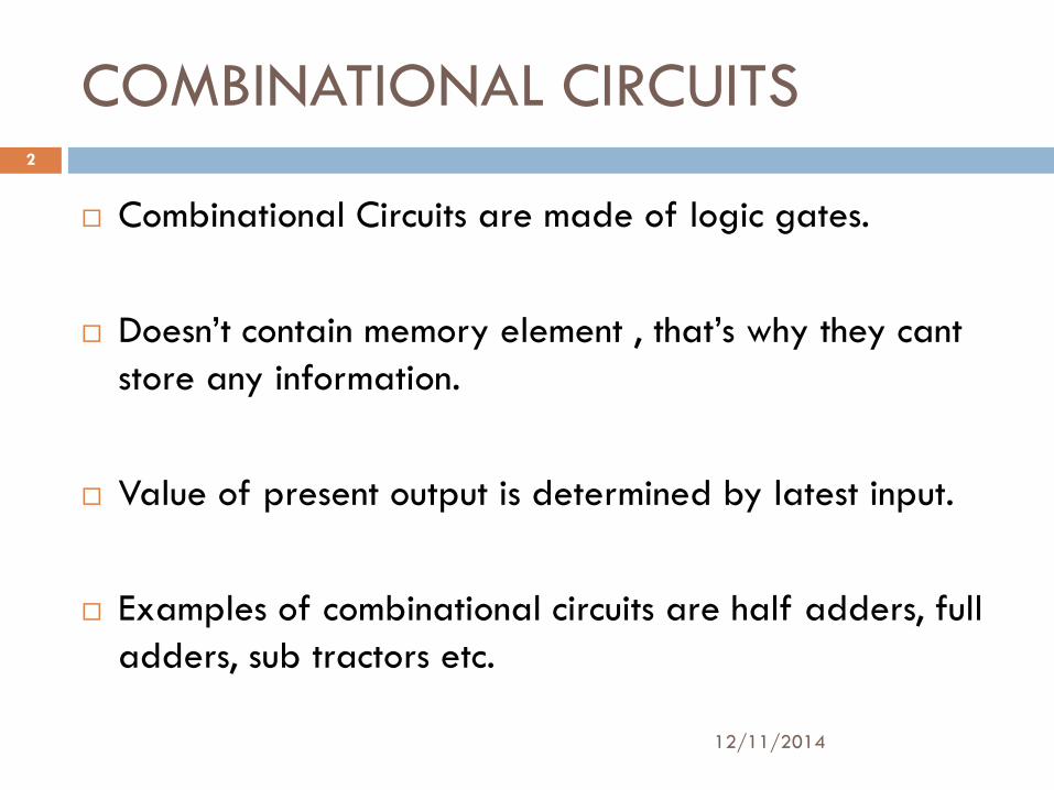
COMBINATIONAL CIRCUITS
Combinational Circuits are made of logic gates.
Doesn’t contain memory element , that’s why they cant store any information.
Value of present output is determined by latest input.
Examples of combinational circuits are half adders, full adders, sub tractors etc.
12/11/2014
2
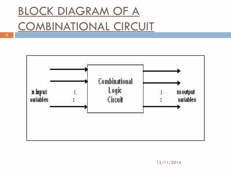
BLOCK DIAGRAM OF A COMBINATIONAL CIRCUIT
12/11/2014
3
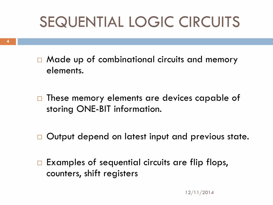
SEQUENTIAL LOGIC CIRCUITS
Made up of combinational circuits and memory elements.
These memory elements are devices capable of storing ONE-BIT information.
Output depend on latest input and previous state.
Examples of sequential circuits are flip flops, counters, shift registers
12/11/2014
4
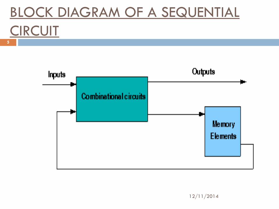
BLOCK DIAGRAM OF A SEQUENTIAL CIRCUIT
12/11/2014
5
TYPES OF SEQUENTIAL CIRCUITS
Sequential circuits are of two types:
1.SYNCHRONOUS CIRCUITS:
In synchronous sequential circuits, the state of the device changes only at discrete times in response to a clock Pulse.
2.ASYNCHRONOUS CIRCUITS:
Asynchronous circuit is not synchronized by a clock signal; the outputs of the circuit change directly in response to changes in Inputs.
12/11/2014
6
12/11/2014
7
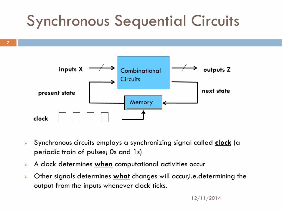
Synchronous Sequential Circuits
Synchronous circuits employs a synchronizing signal called clock (a periodic train of pulses; 0s and 1s)
A clock determines when computational activities occur
Other signals determines what changes will occur,i.e.determining the output from the inputs whenever clock ticks.
Combinational Circuits
inputs X outputs Z
Flip-Flops
next state present state
clock
Memory
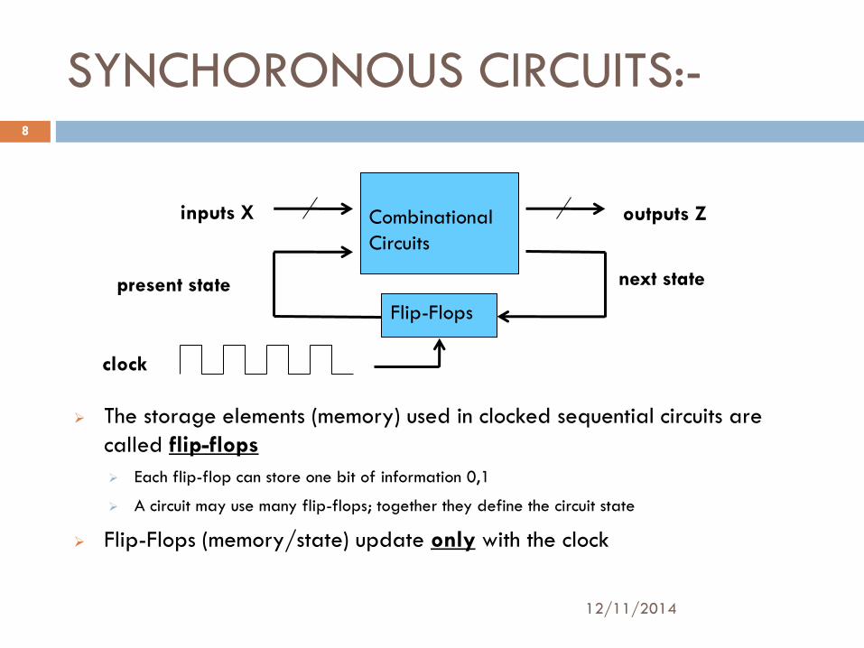
SYNCHORONOUS CIRCUITS:-
12/11/2014
8
The storage elements (memory) used in clocked sequential circuits are called flip-flops
Each flip-flop can store one bit of information 0,1
A circuit may use many flip-flops; together they define the circuit state
Flip-Flops (memory/state) update only with the clock
Combinational Circuits
inputs X outputs Z
Flip-Flops
next state present state
clock
EXAMPLE :--
12/11/2014
9
12/11/2014
10
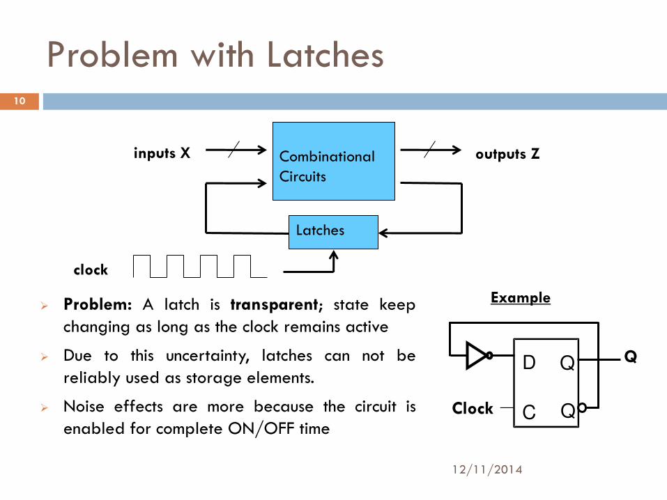
Problem with Latches
Problem: A latch is transparent; state keep changing as long as the clock remains active
Due to this uncertainty, latches can not be reliably used as storage elements.
Noise effects are more because the circuit is enabled for complete ON/OFF time
C
D Q
Q
Q
Clock
Example
Combinational Circuits
inputs X outputs Z
Latches
clock
SEQUENTIAL CIRCUITS…
12/11/2014
11
bistable (2 stable states are stable).....
Bistable logic devices: latches (level) and flip-flops (edge).
Latches and flip-flops differ in the method used for changing their state.
Latches are useful in asynchronous sequential circuits Flip-Flips are built with latches
Flip flop and latch are two basic building blocks of sequentional circuit but there is suitable difference between the two is;
A flip flop continuously checks its inputs and corresponding changes its output only at times determined by clocking the signal.
Where as latch is a device which continuously checks all its inputs and correspondingly changes its output, independent of time determined by clocking signal.
Difference between flip flop and latch
12/11/2014
12
12/11/2014
13
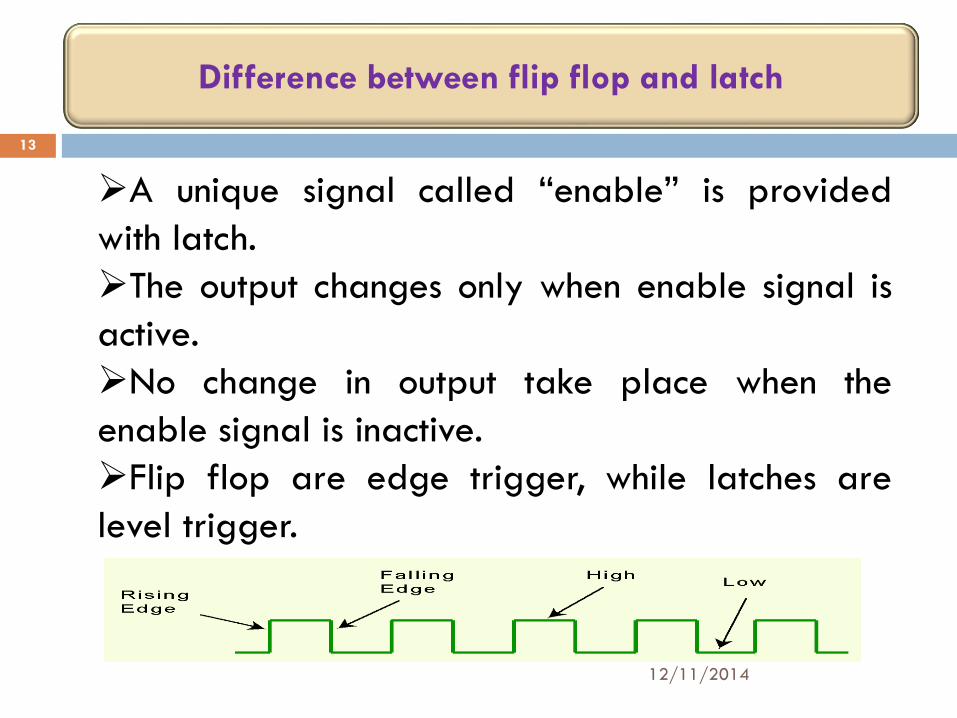
A unique signal called “enable” is provided with latch. The output changes only when enable signal is active. No change in output take place when the enable signal is inactive. Flip flop are edge trigger, while latches are level trigger.
Difference between flip flop and latch
FLIPFLOPS :--
12/11/2014
14
What is Flip flop?
Answer:
In digital circuits, the flip-flop, is a kind
of bistable multivibrator.
It is a Sequential Circuits / an electronic circuit which has two stable states and thereby is capable of serving as one bit of memory , bit 1 or bit 0.
CHARECTERSTICS OF FLIPFLOP…
12/11/2014
15
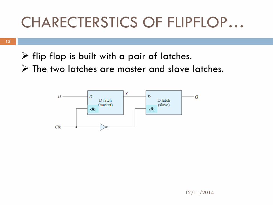
flip flop is built with a pair of latches. The two latches are master and slave latches.
clk clk
CHARECTERSTICS ….(CONT’D)
12/11/2014
16
A master latch receives external inputs
A slave latch receives inputs from the master latch
Depending on the clock signal, only one latch is active at any given time
If clk=1, the master latch is enabled and the inputs are latched if clk=0, the master is disabled and the slave is activated to generate the outputs
The above shown circuit acts as D Flipflop
CHARECTERSTICS….(CONTD)
12/11/2014
17
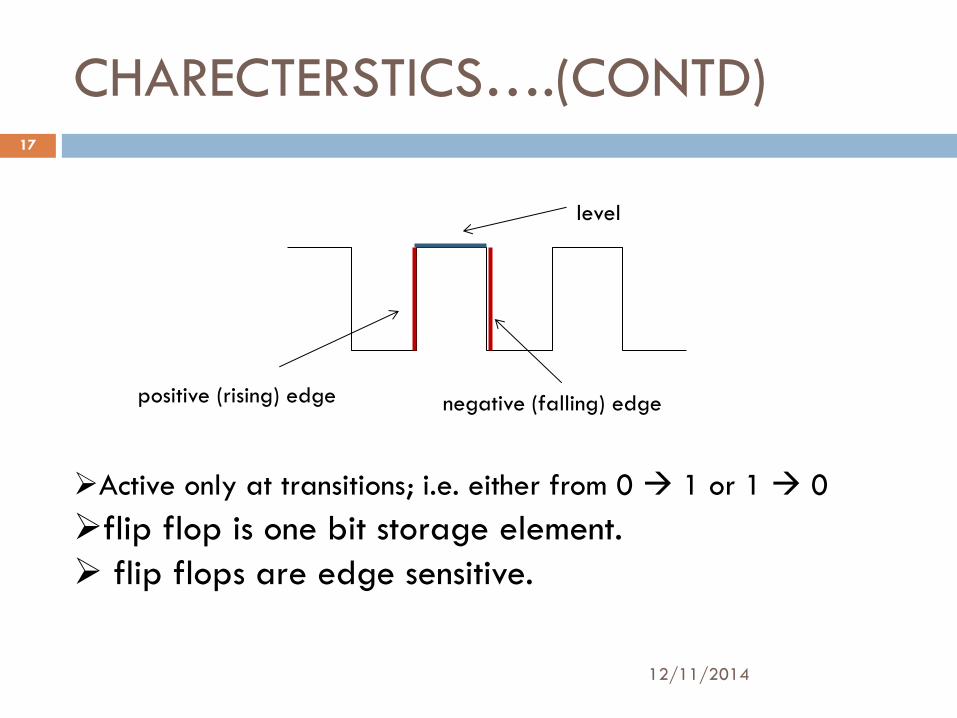
Active only at transitions; i.e. either from 0 1 or 1 0 flip flop is one bit storage element. flip flops are edge sensitive.
positive (rising) edge negative (falling) edge
level
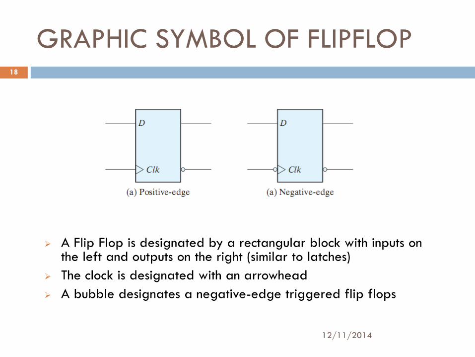
GRAPHIC SYMBOL OF FLIPFLOP
12/11/2014
18
A Flip Flop is designated by a rectangular block with inputs on the left and outputs on the right (similar to latches)
The clock is designated with an arrowhead
A bubble designates a negative-edge triggered flip flops
CHARECTERSTICS …(CONT’D)
12/11/2014
19
ASYNCHRONOUS INPUTS:-- Some flip-flops have asynchronous inputs to set/reset their states independently of the clock. Preset or direct set, sets the flip-flop to 1 Clear or direct reset, set the flip-flop to 0 When power is turned on, a flip-flop state is unknown; Direct inputs are useful to put in a known state
METASTABILITY:--
12/11/2014
20
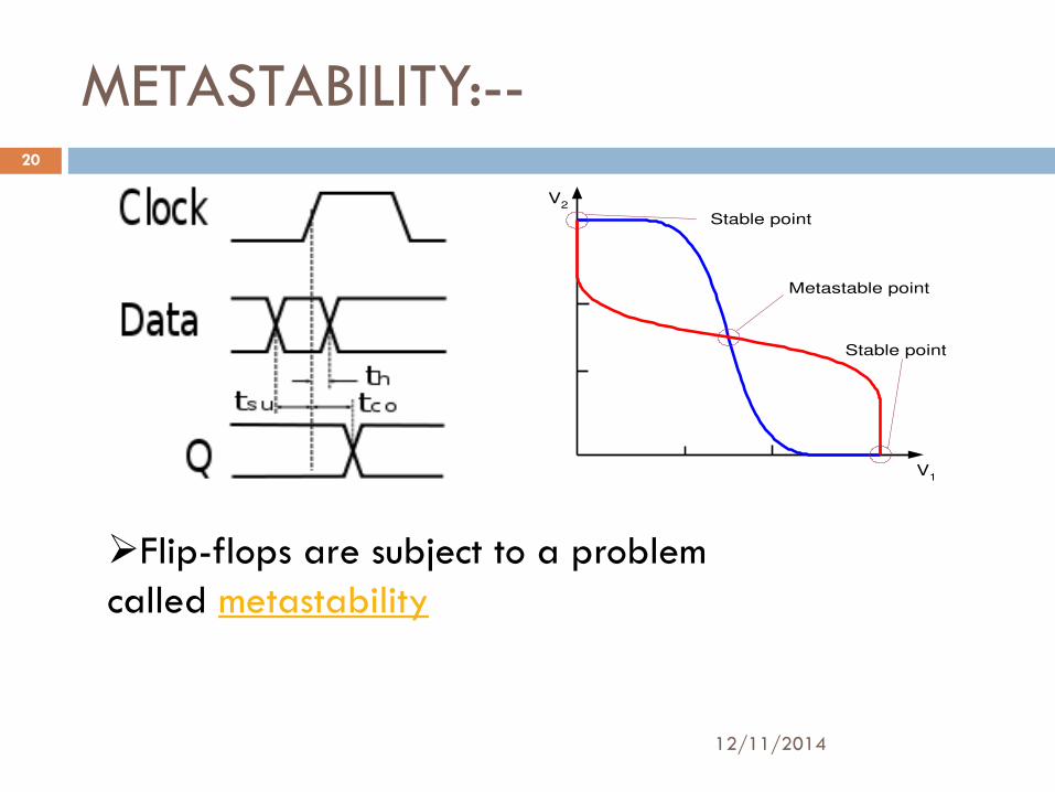
Flip-flops are subject to a problem called metastability
V1
V2
Stable point
Metastable point
Stable point
METASTABILITY:-
12/11/2014
21
metastability condition is occurred because by violating setup and hold time violation. Due to metastability state corruption of data will be occur. Setup time is the minimum amount of time the data signal should be held steady before the clock event so that the data are reliably sampled by the clock. This applies to synchronous input signals to the flip-flop. Hold time is the minimum amount of time the data signal should be held steady after the clock event so that the data are reliably
sampled. This applies to synchronous input signals to the flip-flop.
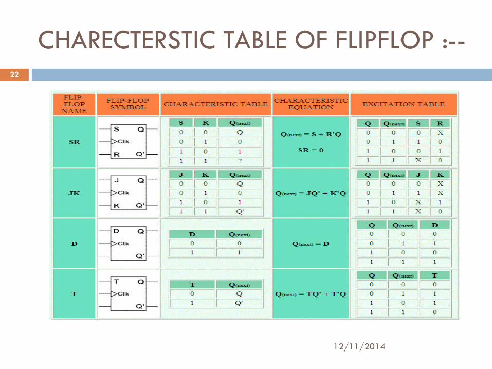
CHARECTERSTIC TABLE OF FLIPFLOP :--
12/11/2014
22

12/11/2014
23