Sea Ray Owner’s Manual€¢ U.S. Coast Guard Auxiliary • U.S. Power Squadron • Canadian Power...
94
Owner’s Manual Part Number: MRP 1803642 Sea Ray Owner’s Manual 220 Sundeck
-
Upload
dangnguyet -
Category
Documents
-
view
217 -
download
4
Transcript of Sea Ray Owner’s Manual€¢ U.S. Coast Guard Auxiliary • U.S. Power Squadron • Canadian Power...

Owner’s Manual Part Number: MRP 1803642
Sea RayOwner’sManual
220 Sundeck


220 Sundeck®
Congratulations on becoming the new owner of theworld’s most prestigious boat. We at Sea Ray®
Boats, Inc. welcome you into our worldwide andever-expanding family of boating enthusiasts.
The Owner’s Manual Packet, to be kept on boardyour Sea Ray, gives you important information onall the features of your Sea Ray, for years of trouble-free boating take the time to carefully review theinformation in your Owner’s Manual Packet andreally get to know your boat. Have everyone whowill operate your boat read this manual.
The Owner’s Manual Packet contains the following:
• Owner’s ManualThe Owner’s Manual gives you importantoperating and safety information, as well asreminding you about your responsibilities as aboat owner/operator.
• Original Equipment Manufacturer (OEM)InformationThis section of your Owner’s Manual Packetcontains information from the manufacturers ofequipment installed on your boat. Examplesinclude the engine, engine control and steeringsystem. Throughout the Owner’s Manual youwill be referred to information provided bymanufacturers of specific systems.
Because your purchase represents a substantialinvestment, we know you will want to take thenecessary measures to protect its value. We haveoutlined a program for proper operation, periodicmaintenance and safety inspections. We urge youto follow these recommendations. If you havequestions which are not fully covered by the Owner’sManual Packet, please consult your authorizeddealer for assistance.
WELCOME
Thank You For Selecting A Sea Ray®!
Bon Voyage
220 Sundeck

220 Sundeck®

220 Sundeck®
INTRODUCTION
1. THIS MANUAL
The material here and in the rest of the Owner’sManual Packet:
• Gives you basic safety information;
• Describes the features of your boat;
• Describes the equipment on your boat;
• Describes the fundamentals of boat use; and
• Contains service and maintenance information.
You must learn to operate this boat as well as read,understand and use this manual.
What this manual does not give you is a course inboating safety, or how to navigate, anchor or dockyou boat. Operating a power boat safely requiresmore skills, knowledge and awareness than isnecessary for a car or truck.
2. YOUR RESPONSIBILITIES
For your safety, the safety of your passengers, otherboaters and people in the water, you must:
• Take a boating safety course;
• Get instruction in the safe and proper handlingof your boat;
• Understand and follow the “rules of the road”;
• Learn how to navigate.
3. SOURCES OF INFORMATION
In North America, contact one of the following forboating courses:
• U.S. Coast Guard Auxiliary
• U.S. Power Squadron
• Canadian Power and Sail Squadrons
• Red Cross
• State Boating Offices
• Yacht Club
Contact your dealer or the Boat/U.S. Foundation at1-800-336-2628
Outside of North America, contact your boat dealerand/or your governmental boating agency forassistance.
A book that provides a comprehensive backgroundin boating is Chapman - Piloting, Seamanship andSmall Boat Handling, by Elbert S. Maloney,published by Hearst Marine.
4. DEALER RESPONSIBILITIES
In addition to a pre-delivery check and service ofthe boat, your dealer is to give you:
• A description and demonstration of the safetysystems, features, instruments and controls onyour boat;
• An orientation in the general operation of yourboat;
• An “In Service Form” completed by you and thedealer after your inspection of the boat;
• A review of all warranty information and how toobtain warranty service;
• The complete Owner’s Manual Packet.
If you do not receive all of these materials, or haveany questions, contact your dealer or call1-800-SRBOATS (International 1-314-216-3333).
5. WARRANTIES
Your boat comes with several warranties. Eachcomponent and/or system on your boat has its ownwarranty that will be found with the specificinformation and manual for that component. Theseare included with your Owner’s Manual Packet.Locate and read the individual warranties; then putthem together for easy future reference. The SeaRay® warranty is on the warranty information cardin your packet and is repeated on the next page.
iii

220 Sundeck®
6. HULL IDENTIFICATION NUMBER
(HIN)The “Hull Identification Number” located on thestarboard side of the transom, is the most importantidentifying factor and must be included in allcorrespondence and orders. Failure to include itcreates delays. Also of vital importance are theengine serial numbers and part numbers whenwriting about or ordering parts for your engine. Referto the Engine Operator’s Manual for locations ofengine serial numbers and record them for futurereference.
7. MANUFACTURER’S CERTIFICATION
A CE mark means that your Sea Ray® Boat hasbeen certified to meet the applicable InternationalOrganization for Standardization directives.
NMMA certification means that your Sea Ray® Boathas been judged by the National MarineManufacturers Association to be in compliance withapplicable federal regulations and American Boatand Yacht Council standards.
The following information is furnished in compliancewith ISO directives and RSG guidelines in effect asof the date of publication of this manual. Sea Ray®
will provide additional information as standards areamended. The following information, required for
export of the vessel, must be filled out by the dealer.
8. SERVICE, PARTS AND REPAIR FOR
YOUR BOAT
When your boat needs service, parts or repair, takeit to an authorized Sea Ray® dealer. To find a dealerin your area call:
1-800-SRBOATSFax: 1-314-213-7878Domestic/International
To find repair and parts facilities for the equipmentinstalled on your boat, refer to the manual for thatcomponent.
If a problem is not handled to your satisfaction:
1. Discuss any warranty-related problems directlywith the service manager of the dealership oryour sales person. Give the dealer anopportunity to help the service departmentresolve the matter for you.
2. If a problem arises that has not been resolvedto your satisfaction by your dealer, contact SeaRay® Boats at 1-800-SRBOATS and theappropriate customer service departmentinformation will be provided to you.
Boat Model:Design Category: Ocean Offshore
Hull Identification Number:Maximum Recommended Load:Recommended Number of Passengers:Maximum Rated Engine Power:Engine InstalledManufacturer:Model and Number:Weight of CraftW/Engine & Permanently Attached Items:Without Engine:
Inshore Sheltered Waters
iv
H.I.N LOCATIONS
(FIG. IV.1)
INTRODUCTION

220 Sundeck® v
ABOUT YOUR LIMITED WARRANTY
Sea Ray offers an express limited warranty on each new Sea Ray sport boat purchased through an authorizedSea Ray dealer. A copy of the Sea Ray Sport Boat Limited Warranty ¨(“Limited Warranty”) was included inyour owner’s packet. If for any reason, you did not receive a copy of the limited warranty, please contact yourlocal dealer or call 1-800-SRBOATS for a replacement copy. This is a summary of several provisions of theLimited Warranty. Please read the Limited Warranty, which is the controlling document.
Under the Limited Warranty, Sea Ray covers: (a) structural fiberglass deck or hull defects which occur withinfive (5) years of the date of delivery; (b) parts found to be defective in factory material or workmanship withinone (1) year of the date of delivery; (c) laminate blisters resulting from defects in factory material or workmanshipfor five (5) years on a prorated basis.On Sport Boats, Sea Ray provides additional warranty coverage to its five-year structural hull/deck coveragewith a limited life-time structural hull/deck warranty. This limited lifetime structural coverage provides repairsof any Structural Fiberglass Hull/Deck Defect for as long as the original owner owns the Sport Boat. SportBoat models and Hull/Deck Defects are defined in the Limited Warranty.
Sea Ray’s obligation under its Limited Warranty is limited to repair or replacement of parts that are judgeddefective by Sea Ray and does not include transportation, haul out, or other expenses. The foregoing is the soleand exclusive remedy provided by Sea Ray.
The Limited Warranty does not cover engines, stern drives, controls, propellers, batteries, trailers, or otherequipment or accessories carrying their own individual warranties, nor does the Limited Warranty cover engines,parts or accessories not installed by Sea Ray. The Limited Warranty does not cover cosmetic gel coat finish.Boats used for commercial purpose are excluded from coverage. See the Limited Warranty for other exclusions.
SEA RAY EXPRESSLY DISCLAIMS THE IMPLIED WARRANTIES OF FITNESS ANDMERCHANTABILITY. NEITHER SEA RAY NOR THE SELLING DEALER SHALL HAVE ANYRESPONSIBILITY FOR LOSS OF USE OF THE BOAT, LOSS OF TIME, INCONVENIENCE,COMMERCIAL LOSS OR CONSEQUENTIAL DAMAGES.
The unexpired term on the limited one-year parts and components coverage and the limited five-year pro-ratedblister coverage of the Limited Warranty may be transferred to a subsequent owner upon the new owner’swritten request. Coverage for Structural Fiberglass Hull/Deck Defects on Sport Boats may be transferred onceto a second owner upon the second owner’s request, however upon transfer, this coverage will expire ten (10)years from the date of original purchase by the first retail owner, as reflected in Sea Ray’s records.
The new owner can submit a request for warranty transfer, free of charge, via the searay.com website.Alternatively, the new owner can submit a written request to the Sea Ray Division of Brunswick Corporation,2600 Sea Ray Blvd., Knoxville, TN 37914, accompanied by a $50 processing fee.
Thank you for your decision to buy a Sea Ray.
The Limited Warranty is subject to change at any time at Sea Ray’s discretion. The information contained herein is generalinformation about the Limited Warranty for the owner’s general knowledge, and does not alter or amend the terms of theLimited Warranty.
®

220 Sundeck®
220 SUNDECK® OWNER’S MANUAL • TABLE OF CONTENTS
INTRODUCTION
1. This Manual ............................................................. iii2. Your Responsibilities ............................................... iii3. Source of Information ............................................... iii4. Dealer Responsibilities ............................................. iii5. Warranties ............................................................... iii6. Hull Identification Number (HIN) ............................... iv7. Manufacturer’s Certificate ......................................... iv8. Service, Parts and Repair for Your Boat .................... iv9. Express Limited Transferable Warranty ..................... v
SECTION 1 • SAFETY
1. Safety Labels ........................................................ 1.12. Legally Mandated Minimum Required Equipment . 1.23. Fire Extinguishing Equipment ................................ 1.24. Carbon Monoxide.................................................. 1.25. Life Saving Equipment .......................................... 1.3
A. PFD Classifications ....................................... 1.46. Additional Recommended Equipment for Safe Operation ...................................................... 1.57. Impaired Operation ............................................... 1.58. Load Capacity ....................................................... 1.59. Power Capacity ..................................................... 1.610. Stability ............................................................... 1.711. Maintain Control .................................................. 1.7
A. General Considerations ................................. 1.712. Weather .............................................................. 1.8
A. Ocean ........................................................... 1.8B. Offshore ........................................................ 1.8C. Inshore .......................................................... 1.8D. Sheltered Waters .......................................... 1.8
13. Chart Your Course .............................................. 1.914. Water Sports ....................................................... 1.9
A. Swimming ..................................................... 1.9B. Skiing .......................................................... 1.10C. Diving ......................................................... 1.10
15. Emergency Situations ....................................... 1.11A. Medical Emergency .................................... 1.11B. Water Rescue ............................................. 1.11C. Fire ............................................................. 1.11D. Flooding, Swamping and Capsizing ............ 1.12E. Collisions and Leaking ................................ 1.12F. Grounding ................................................... 1.12G. Propulsion, Control or Steering Failure........ 1.12
16. Safety Hotlines .................................................. 1.1317. International Requirements ............................... 1.1318. Environmental Considerations .......................... 1.13
A. Fuel and Oil Spillage ................................... 1.13B. Waste Disposal ........................................... 1.14C. Excessive Noise ......................................... 1.14D. Wake / Wash .............................................. 1.14
SECTION 2 • GENERAL BOAT ARRANGEMENT
1. Docking/Lifting/Trailering ........................................ 2.12. Passenger Locations ............................................. 2.13. Propulsion System ................................................ 2.24. Basic Boat Dimensions and Clearances ............... 2.35. Propellers ............................................................. 2.36. General Deck Layout ............................................ 2.47. Helm Gauge and Switch Layout ............................ 2.58. Function and Location of Thru-Hull Cutouts ........... 2.69. Description of Major Controls ................................ 2.7
A. Gear Shift and Throttle Control ...................... 2.7B. Power Trim Unit and Gauge .......................... 2.7C. Trailer Switch ................................................ 2.8D. Transom Trailer Trim Switch (Optional) ......... 2.8E. Ignition Shutdown Switch (Standard on Side
Mount Controls) .............................................. 2.8F. Engine Alarm System (Only on Certain Engines) ........................... 2.9
10. Important Gauges ............................................... 2.9A. SmartCraft™ Gauge System ......................... 2.9B. Tachometer .................................................. 2.10C. Oil Pressure, Water Temperature and Fuel Gauges ............................................... 2.10D. Magnetic Compass ...................................... 2.10
11. Navigation and Anchor Light ............................. 2.10
SECTION 3 • USING YOUR BOAT
1. Pre-Launch, Launch and Post-Launch Checklist ... 3.12. Trailer Launching and Loading ............................... 3.23. Fueling the Boat .................................................... 3.24. Boarding ............................................................... 3.35. Personal Flotation Devices (PFDs) ........................ 3.46. Passenger Instruction and Location ...................... 3.47. Starting the Engines ............................................. 3.48. Shifting to Drive the Boat ...................................... 3.69. Stopping the Engines ............................................ 3.610. Steering System ................................................. 3.7
SECTION 4 • BILGE & UNDERWATER GEAR
1. Bilge ..................................................................... 4.1A. Fuel & Oil Spillage ......................................... 4.1B. Drain Plug ..................................................... 4.1C. Bilge Pump ................................................... 4.1D. Bilge Blower System ..................................... 4.2E. Engine and Stern Drive ................................. 4.3F. Bilge Layout .................................................. 4.5
vi
19. Nautical Terms.................................................. 1.1420. Key to Symbols on Controls & Prints ................. 1.1621. 220 SD Warning Label Locations ...................... 1.17

220 Sundeck®
220 SUNDECK® OWNER’S MANUAL • TABLE OF CONTENTS
SECTION 5 • FUEL SYSTEM
1. Fuel System ......................................................... 5.1A. Electric Fuel Valve ........................................ 5.1
2. Fueling Precautions .............................................. 5.2A. General ......................................................... 5.2B. Before & During Fueling - Checklist ............... 5.2C. After Fueling - Checklist ................................ 5.2
SECTION 6 • ELECTRICAL SYSTEM
1. Electrical System .................................................. 6.1A. Direct Current (DC) ....................................... 6.1B. Battery Switch (Optional) .............................. 6.3
2. Ignition Protection ................................................. 6.33. Fuses .................................................................... 6.44. Lighting ................................................................. 6.55. 12 Volt Accessory Receptacle ............................... 6.56. Electrolytic Corrosion and Zinc Anodes ................. 6.57. Electrical Schematics ............................................ 6.6
SECTION 7 • OPTIONS & ACCESSORIES
1. Boat Layout and Accessory Locations ................... 7.12. Control Station Seating ......................................... 7.23. Bow Rider Filler Cushions (Optional) .................... 7.24. Cockpit Table, Table Support & Trash Can
Storage ............................................................. 7.25. 12 Volt Receptacle ................................................ 7.36. Entertainment System........................................... 7.37. Steering Wheel Remote Controls .......................... 7.48. Transom Trailer Trim Switch (Optional) ................. 7.59. Magnetic Compass (Optional) ............................... 7.510. Navigation and Anchor Lights ............................. 7.511. Water Sport Tower (Optional) ............................. 7.612. Fire Extinguisher Port .......................................... 7.613. Swim Platform and Ladder .................................. 7.714. Automatic Fire Extinguisher System (Optional) ... 7.715. Water System ..................................................... 7.7
A. Sanitizing The Water System ........................ 7.8B. Winterizing The Water System ...................... 7.8C. Water Pump And Filter .................................. 7.8D. Fresh Water And Drain Line Routing .......... 7.10
16. CorsaTM Thru-Hull Exhaust System (Optional) .. 7.1217. Toilet (Head) System ........................................ 7.13
SECTION 8 • REQUIRED INSPECTION, SERVICE AND
MAINTENANCE
1. Summary Guide for Inspection, Service and Maintenance .................................................. 8.12. Inspection, Service and Maintenance Protocol ..... 8.3
A. Bilge Area ..................................................... 8.3B. Topside and Supplies .................................... 8.4
3. Winterization Checklist for Boats Stored on Land .. 8.4A. Boat Storage ................................................. 8.4B. Engines ......................................................... 8.4C. Battery .......................................................... 8.4D. Fuel System .................................................. 8.5
4. Fitting Out After Storage........................................ 8.5A. Fuel System .................................................. 8.5B. Battery .......................................................... 8.5C. Miscellaneous ............................................... 8.5
5. Security Considerations ........................................ 8.56. Power Steering System Maintenance .................... 8.57. Engine Oil Change ................................................ 8.6
SECTION 9 • CARE & REFINISHING
1. Paint, Cleaning Agents and Other Substances ..... 9.12. Fiberglass & Gelcoat ............................................. 9.13. Stains & Scratches ............................................... 9.14. Permanently Moored or Docked Boats.................. 9.25. Care for Bottom Paint ........................................... 9.26. Topside Areas ....................................................... 9.2
A. Stainless Steel and Alloy Fittings ................... 9.2B. Salt Crystals ................................................. 9.2
7. Acrylic Plastic Sheeting (Plastic Glass) ................. 9.28. Canvas and Clear Vinyl ......................................... 9.29. Exterior Upholstery Fabric ..................................... 9.3
A. Portable Self-Contained Head ..................... 7.13B. Pump-Out -Head (Optional) ........................ 7.13
18. Canvas ............................................................. 7.14A. Installation Tips ........................................... 7.15B. Trailering with Canvas ................................. 7.15C. Canvas Care and Maintenance................... 7.15D. Docking Lights (Optional) ............................ 7.15
vii

220 Sundeck®
Information in this publication is based upon the latest product specifications available at printing. Sea Ray® Boats,Inc. reserves the right to make changes at any time, without notice, in the colors, equipment, specifications, materialsand prices of all models, or to discontinue models. Should changes in production models be made, Sea Ray® is not
obligated to make similar changes or modifications to models sold prior to the date of such changes.
220 Sundeck® Owner’s ManualPrinted in the U.S.A November, 2001
Revised: September 2002, June 2004, July 2005© Sea Ray Boats, Inc. • A Brunswick Company
MRP #1803642
Sea Ray Boats, Inc. 2600 Sea Ray Blvd. , Knoxville, TN 37914For information call 1-800-SRBOATS or fax 1-314-213-7878
(International 1-314-216-3333)
The following are registered trademarks of the Brunswick Corporation: Sea Ray® & The SR Wave Logo
220 SUNDECK® OWNER’S MANUAL • TABLE OF CONTENTS

220 Sundeck® 1.1
SECTION 1 • SAFETY
SAFE boating means:
• Knowing the limitations of your boat;
• Following the rules of the road;
• Keeping a sharp lookout for people and objectsin the water;
• Not boating in water or weather conditions thatare beyond the boat’s and the operator’scapability;
• Never go boating when the operator is underthe influence of drugs or alcohol;
• Being aware of your passenger’s safety at alltimes; and
• Reducing speed when there is limited visibility,rough water, nearby people in the water, boats,or structures.
Boating in beautiful weather and calm waterconditions can be a wonderful experience.Pleasurable boating, however, requires considerablygreater skills than operating a land vehicle. To obtainthese skills, you must:
• Take a Coast Guard, U.S. Power Squadron orequivalent boating safety course. Call the Boat/U.S. Foundation at 1-800-336-2628 forinformation on available courses.
• Get hands-on training on how to operate yourboat properly.
In addition:
• Maintain your boat and its safety and othersystems as recommended in this manual.
• Have the boat inspected by a qualified mechanicor dealer, at least annually.
• Ensure that the Coast Guard required safetyequipment is on board and functions. (See page1.2).
DANGER – Immediate hazards which WILL result insevere personal injury or death if the warning isignored.
! DANGER
WARNING – Hazards or unsafe practices whichCOULD result in severe personal injury or death ifthe warning is ignored.
! WARNING
CAUTION – Hazards or unsafe practices which couldresult in minor injury or product or property damageif the warning is ignored.
! CAUTION
Information which is important to proper operationor maintenance, but is not hazard-related.
NOTICE
1. SAFETY LABELS
Safety precautions are given throughout this manualand labels are mounted at key locations throughoutthe boat. This safety information advises the owner/operator and passengers of imperative safetyprecautions to follow when operating and/orservicing equipment.
• Figures 1.17.1 and 1.18.1 show the location ofthe safety labels on your boat.
• Do not remove or obstruct any safety label.
• Replace any label which becomes illegible.Replacement safety labels can be obtained bycalling your dealer or Sea Ray at 1-800-SRBOATS (international 1-314-216-3333) forinformation on how to contact the manufacturingfacility for your boat.
The meaning associated with each of the four basictypes of label is:

220 Sundeck®1.2
SECTION 1 • SAFETY
4. CARBON MONOXIDE
Symptoms of carbon monoxide poisoning aredizziness, ears ringing, headaches, nausea andunconsciousness. A poisoning victim’s skin oftenturns cherry red. Because carbon monoxide gas(CO) is odorless, colorless and tasteless, it isunlikely to be noticed until a person is overcome.
Dangerous concentrations of carbon monoxide willbe present if:
• the engine and/or generator exhaust systemsleak;
3. FIRE EXTINGUISHING SYSTEM
Your boat is equipped with an automatic fireextinguisher system. Located in the enginecompartment. In the event of a fire, the heatsensitive automatic head in the engine compartmentwill release a fire-extinguishing vapor, totallyflooding the area.
There is an indicator light for the automatic fireextinguishing system next to the ignition key at thecontrol station. The light will be ON when the ignitionis on and indicates that the system is ready. If thelight goes out while the ignition is on, the systemhas discharged.
WHEN DISCHARGE OCCURS, IMMEDIATELYSHUT DOWN ALL ENGINES, POWEREDVENTILATION, ELECTRICAL SYSTEMS ANDEXTINGUISH ALL SMOKING MATERIALS. DONOT IMMEDIATELY OPEN THE ENGINECOMPARTMENT! THIS FEEDS OXYGEN TO THEFIRE AND THE FIRE COULD RESTART.
Wait at least fifteen (15) minutes before openingthe engine compartment. This permits the fire-extinguishing vapor to “soak” the compartment longenough for hot metals and fuels to cool. Haveportable extinguishers at hand and ready to use incase the fire reignites. Do not breathe fumes orvapors caused by the fire.
2. LEGALLY MANDATED MINIMUM
REQUIRED EQUIPMENT
Consult your national boating law enforcementagency.
The following equipment is the minimum requiredby the U.S. Coast Guard for a boat less than 26’[7.9 meters] in length.
Personal Flotation Devices (PFD’s): One CoastGuard approved Type I, II or III device is mandatoryfor each person aboard. One throwable Type IVdevice is also required to be on board. A Type Vdevice is acceptable if worn for approved use. SeePage 1.5 for a description of these PFDclassifications. Always wear a PFD when boating.
Fire Extinguisher - Portable: If no fixed fireextinguishing system is installed in the engine andgenerator spaces, the U.S. Coast Guard requiresone (1) Type B-1 fire extinguisher be on board.The American Boat and Yacht Council (ABYC)recommends that you have two (2) Type B-1 ABCfire extinguishers on board. One is to be located atthe helm station and the other in the cabin, nearthe cockpit door.
Whistle, Horn: You must have on board somemeans of making a loud sound signal, for example,whistle or horn.
Visual Distress Signals: If you operate your boatin coastal waters or on the Great Lakes, you musthave visual distress signals for day and night useon board. At least three (3) U.S. Coast Guardapproved pyrotechnic devices marked with dateshowing service life must be carried, be readilyaccessible, in serviceable condition and not expired.Store pyrotechnic signals in a well-markedwaterproof container in a dry location.
Other: Your Sea Ray is equipped with the requirednavigation lights, engine exhaust and ventilationsystems.

220 Sundeck® 1.3
SECTION 1 • SAFETY
Fumes from engine, generators, and other equipmentand appliances using burning fuel contain carbonmonoxide.
Carbon Monoxide can kill you.
Open all doors, curtains, windows, and hatches to letfresh air circulate, when running engine, generatoror burning any fuel when boat is anchored, mooredor docked.
! DANGER
Even in rainy cold weather ventilation must bemaintained to avoid Carbon Monoxide poisoning. Youwill get wet and/or cold.
! DANGER
Sleeping on boat requires a operating CarbonMonoxide detection system in each sleeping location.
! DANGER
5. LIFESAVING EQUIPMENT
Even strong swimmers can tire quickly in the waterand drown due to exhaustion, hypothermia, or both.The buoyancy provided by a personal flotationdevice (PFD) will allow the person who has fallenoverboard to remain afloat with far less effort andheat loss, extending survival time necessary to findand retrieve them.
Boat operators are required to carry one wearablepersonal flotation device (Type I,II,III or V) for everyperson on board. Boats must also have at least onethrowable device (Type IV).
The law requires that PFD’s must be readilyaccessible, if not worn. “Readily accessible” meansremoved from storage bags and unbuckled. But,children and nonswimmers must wear PFDs at alltimes when aboard. It is common sense to haveeveryone on board wearing PFDs. A throwabledevice must also be right at hand and ready to toss.
• insufficient fresh air is circulating where peopleare present; and
• fumes move from the rear of the boat into thecockpit and cabin area.
Figure 1.4.1 gives examples of boat operatingconditions that can lead to high concentrations ofcarbon monoxide gas.
To minimize the danger of CO accumulation whenthe engine and/or generator are running, or usingburning fuel applications.
• Be sure to have sufficient ventilation when usingcanvas or window-type side curtains whenunderway, anchored, moored or docked.
• If the convertible top is installed, operate withthe forward hatch open and leave cabin dooropen.
• Operate all burning fuel appliances, such ascharcoal, propane, LPG, CNG or alcoholcooking devices in areas where fresh air cancirculate. Do not use such devices where thereis no noticeable air movement, especially in thecabin, when anchored, moored or docked.
• Do not idle engine without moving boat for morethan 15 minutes at a time.
• Inspect the exhaust system regularly. (SeeSection 8, Required Inspection, Service andMaintenance.
If CO poisoning is suspected, have the victim breathfresh air deeply. If breathing stops, resuscitate. Avictim often revives, then relapses because organsare damaged by lack of oxygen. Seek immediatemedical attention.

220 Sundeck®1.4
SECTION 1 • SAFETY
EXAMPLES OF HOW HIGH LEVELS OF CARBONMONOXIDE MAY ACCUMULATE(FIG. 1.4.1)
USING CANVAS OPERATING WITH THE BOW HIGH.
WINDS BLOWING EXHAUST TOWARDBOAT OCCUPANTS.
FOR GOOD VENTILATION: REMOVE FRONTCURTAIN, SIDE CURTAIN, OPEN WINDSHIELDAND FORWARD WALK-THROUGH DOOR.
BLOCKING HULL EXHAUSTS. OPERATINGAT SLOW SPEED OR DEAD IN THE WATER.
OPERATING ENGINE AND/ORGENERATOR IN CONFINED SPACES.ILLUSTRATION #A
ILLUSTRATION #B
ILLUSTRATION #C
ILLUSTRATION #D
ILLUSTRATION #E
ILLUSTRATION #F
A. PFD CLASSIFICATIONS
Off-Shore Life Jacket (Type I) –most buoyant, it is designed toturn an unconscious person faceup; used in all types of waterswhere rescue may be slow,particularly in cold or roughconditions.
Near-Shore Life Vest (Type II) –“keyhole” vest with flotation-filledhead and neck support is alsodesigned to turn a person face up,but the turning action is not aspronounced; used in calm, inlandwaters or where quick rescue islikely.
Flotation Aid (Type III) – vest isdesigned so conscious wearerscan turn face up; often designedfor comfort while engaged insports such as skiing.
Throwable Devices (Type IV) –horseshoe buoys, ring buoys andbuoyant cushions are designed tobe grasped, not worn.
Special-Use Devices (Type V) –sailboat harnesses, white-watervests, float coats, and hybridvests which have minimuminherent buoyancy and aninflatable chamber.
Before purchasing PFDs, ensurethat there is an attached tag indicating they areapproved by the U.S. Coast Guard or by yournational boating law enforcement agency.
Children and nonswimmers must wear PFDs atall times when aboard. All passengers and crewshould wear them. A loose PFD is often useless inan emergency.
(FIG. 1.4.4)
(FIG. 1.4.2)
(FIG. 1.4.3)
(FIG. 1.4.5)
(FIG. 1.4.6)

220 Sundeck® 1.5
SECTION 1 • SAFETY
Drugs and/or alcohol impair the operator’s ability tocontrol the boat safely.
Death or serious injury can result from improper boatoperation.
! WARNING
8. LOAD CAPACITY
The certification plate (See figure 1.6.1) locatednear the helm indicates maximum weight andnumber of persons your boat can handle under calmsea conditions. Do not exceed the load capacitiesstated. The number of people on board must be
7. IMPAIRED OPERATION
Drugs and/or alcohol will prevent you from operatingyour boat safely. This single factor is involved inmore marine accidents and deaths than any other.The detrimental effects of alcohol and drugs areincreased by the wind, waves and sun, quicklyimpairing your ability to react properly and promptlyin an emergency.
6. ADDITIONAL RECOMMENDED
EQUIPMENT FOR SAFE OPERATION
In addition to legally mandated equipment, thefollowing items are necessary for safe boating,especially if your boat is out of sight of land.
• First aid kit
• Visual distress signals for day and night use(required in some areas; consult localregulations)
• Charts of your intended cruising area
• Compass
• GPS or Loran position locating devices
• Marine VHF radio with weather channels
• Emergency position-indicating radio beacon(EPIRB)
• Manual bilge pump
• Moisture repellant
• Anchors, chain and line (The anchors must beproperly sized for your boat. Ask your dealer ormarine supply store for recommendations).
• Mooring lines
• Fenders
• Boat hook
• Waterproof flashlight(s)
• Extra batteries for flashlights and portableelectronic devices
• High power spotlight, if you intend to boat atnight
• Spare keys
• Instruction manuals for engine and accessories
• Lubricating oil
• Tool kit:
- Assorted screwdrivers (Phillips and flat blade)
- Pliers (regular, vise-grip, and tongue & groove)
- Wrenches (box, open-end, allen, adjustable)
- Socket set (metric or U.S. Standard as appropriate)
- Electrical tape and duct tape
- Hammer
- Utility Knife
• Spare parts kit (spark plugs, fuses, hose clampsand ask your dealer to recommend other parts)
• Extra propeller
The operator is responsible for instructing everyoneaboard on the location and use of PFDs.
Size PFDs for the wearer. Children require specialattention in the use of PFDs.
Test PFD buoyancy at least once a year.

220 Sundeck®1.6
SECTION 1 • SAFETY
When engine is running, keep passengers away fromareas not designed for riding, such as seat backs,bow, gunwales, transom platform, swim platform,front and rear decks and on sun pads.
Passengers can fall overboard if not seated properlyon the seats provided.
! WARNING
Never carry more weight or passengers than indicatedon the certification plate, regardless of weather orwater conditions.
The boat can capsize, swamp or sink.
! DANGER
BUILDER’S PLATE (INTERNATIONAL)(FIG. 1.6.1)
BOAT MANUFACTURERMFR’S MODELDESIGNATION
MAXIMUM NUMBEROF PASSENGERS
MAXIMUM LOADCAPACITY
BUILDER’S PLATE (DOMESTIC)(FIG. 1.6.2)
9. POWER CAPACITY
Do not exceed the maximum engine power ratingstated on the certification plate. Your boat will bedifficult to handle and will be less stable.
Your Sea Ray® has been equipped with a propellerwhich our tests have shown to be the best suitedfor general use with our engine under normalconditions and load. Do not change the pitch of yourpropeller without getting your dealer’srecommendations first. If you change to a differentpropeller pitch, under no circumstances use apropeller which allows the engine to operate athigher than recommended RPM. (your enginemanual specifies the maximum recommended(RPM).
To maintain rated power, propellers should be freeof nicks, excessive pitting and any distortions thatalter them from their original design. Badly damagedpropellers should be replaced, but those that are
reduced if you go out in poor weather and roughwater.
The information present on the certification platedoes not relieve the operator from responsibility.Use common sense and sound judgement whenplacing equipment and/or passengers in your boat.
• Do not load to capacity in poor weather or roughwater.
• The number of seats does not indicate howmany people a boat can carry in poor weatherand rough water.
• Above idle speed, all passengers must beseated on the seats provided.
Sea Ray Boats220 SD
MAXIMUM
10 + = 820 kg
C E0609
CIMCI
MAXIMUM CAPACITIES
10 PERSONS OR 1600 LBS.1800 POUNDS, PERSONS, GEAR
LOAD AND CAPACITY • COMPARTMENT VENTILATIONSTEERING, FUEL AND ELECTRICAL SYSTEMS
INTERNATIONAL LIGHTS • BASIC FLOATIONMANEUVERABILITY
THIS BOAT COMPLIES WITH U.S. COAST
GUARD SAFETY STANDARDS IN EFFECT ON
THE DATE OF CERTIFICATION
MODEL: 220SD
DESIGN COMPLIANCE WITH NMMA REQUIREMENTS BELOW ISVERIFIED. MFR. RESPONSIBLE FOR PRODUCTION CONTROL
NATIONAL MARINE MANUFACTURERS ASSN.
MANUFACTURER: SEA RAY BOATS, INC.
Tellico, TN
CertifiedNMMA

220 Sundeck® 1.7
SECTION 1 • SAFETY
Distribute passengers and gear as uniformly aspossible from front to rear and left to right.
The manufacturer’s load rating is the maximumallowed under calm conditions.
Reduce boat loading if weather, water or otherconditions are adverse.
! WARNING
Death or serious injury can result if you fail to observethese safety rules:
• Anyone who controls the boat must havetaken a boating safety course and havetrained in the proper operation of theboat.
• Always operate the boat at speeds thatwill not put people or property in danger.
• Be constantly aware of conditions in alldirections when underway and beforeturning.
• Reduce speed, use a lookout to identifypossible hazards or difficulties, and turnon navigation lights when:
- visibility is impaired;
- in rough water; and
- in congested waterways.
• Watch your wake. It can capsize a smallboat or damage moored boats or otherproperty. You are responsible for damagecaused by your wake.
! WARNING
11. MAINTAIN CONTROL
On the water there are no marked traffic lanes, notraffic signs or lights, and boats have no turn signals.The boat operator must keep her or his attentionfocused not only on what’s ahead but what’s on theleft, right and behind the boat.
The operator must always be alert to approachingboats (from the rear, right and left sides, as well asthose ahead). There can be people in the water,partially submerged debris, and other navigationalhazards such as rocks, sand bars, dangerouscurrents, to name a few.
Your passengers are relying on you to operate andmaneuver the boat safely so that they are not indanger of going overboard. If you turn to quickly,increase or decrease speed abruptly, yourpassengers are at risk of being thrown overboardor thrown about the boat.
When visibility becomes impaired because ofweather, time of day or high bow angle you mustslow down so that you have sufficient time to reactif an emergency occurs. Nearby boats face similarrisks in avoiding a collision with you.
A. GENERAL CONSIDERATIONS
• Know how your boat handles under differentconditions. Recognize your limitations and theboat’s limitations. Modify speed in keeping withweather, sea and traffic conditions.
10. STABILITY
Your boat was manufactured to specific stability andflotation standards for the capacity shown on thecertification plate. Any increase from therecommended load capacities will put your boat injeopardy of capsizing, swamping and/or sinking.
IN ADDITION:
• Stability may be substantially reduced ifequipment is added above the deck.
• Stability is substantially reduced by loose fluidsor weight within the hull. Keep bilge area as dryas possible, and close all openings, hatches andwindows in rough weather.
chipped, bent or merely out of shape can bereconditioned by your marine dealer.
It is advisable to carry an extra propeller aboard incase you damage the one in use.

220 Sundeck®1.8
SECTION 1 • SAFETY
DO NOT ATTEMPT TO BOAT INSEVERE WEATHER CONDITIONS
DEATH OR SERIOUS INJURY CAN OCCUR
GET TO SHORE BEFORETHE WEATHER TURNS BAD
! DANGER
12. WEATHER
There are four design categories of boats basedupon their ability to withstand wind and sea or waterconditions:
A. OceanWind speed: above 40 knots (46 mph)Wave height: above 4 meters (13 feet)Boat may be used for extended oceanvoyages.
B. OffshoreMaximum wind speed: 40 knots (46 mph)Maximum wave height: 4 meters (13 feet)Boat can be used offshore, but not forextended ocean voyages.
C. InshoreMaximum wind speed: 27 knots (31 mph)Maximum wave height: 2 meters (6.5 feet)Boat use is limited to coastal waters, largebays, estuaries, lakes and rivers.
D. Sheltered watersMaximum wind speed: 15 knots (18 mph)Maximum wave height: 0.5 meters (1.5 feet)Boat use is limited to small lakes, rivers andcanals.
Your 220 Sundeck® is Design Category C.
The wind speed and wave height specified as theupper limit for your category of boat does not meanthat you or your passengers can survive if your boatis exposed to these conditions. It is only the mostexperienced operators and crew that may be ableto operate a boat safely under these conditions. You
must always be aware of weather conditions andhead for port or protected waters in sufficient timeto avoid being caught in high winds and rough water.Do not take chances!
Getting caught in severe weather is hazardous. Badweather and/or rough sea or water conditions cancause an unsafe situation. Consult local weatherinformation, or listen to the NOAA weather reportsfor the latest weather conditions or any impendingdeterioration of the weather before setting out andwhile underway. Following are a few basic weather-related rules:
• Check the weather forecast and the waterconditions before leaving and while underway.
• A sudden change in wind direction or speed oran increase in wave height indicatesdeteriorating weather.
• Have everyone wear a personal flotation device.
• If a storm approaches, immediately seek a safeharbor.
• If a storm hits, have everyone sit in the cabin oron the cockpit deck in the boat. Head the bowinto the wind with enough power to maintainslow headway.
• If you encounter fog, determine your position,set a safe course, slow down and alert otherboats of your presence with a sound signal.
• If a lightning storm approaches, the safest actionis to dock and disembark. If you cannot returnto shore, have passengers go inside the cabinand remain there until the storm passes.
• Instruct passengers on location and use ofsafety equipment and procedures.
• Instruct passengers on the fundamentals ofoperating your boat in case you are unable todo so.
• You are responsible for passenger’s actions. Ifthey place themselves or the boat in danger,immediately correct them.
Observe the safety rules listed below.

220 Sundeck® 1.9
SECTION 1 • SAFETY
Shut engine off if an object is struck or if you runaground.
Check for hull leaks and drive line damage, beforerestarting engines.
Use hand pump if bilge pumps don’t remove water.
Boat very slowly, if you must proceed with a damageddrive line.
! WARNING
Hitting an object in or under the water or boating indangerous currents can cause serious injury or deathto boat occupants.
You must know where the hazards are and avoid them.
In uncharted waters, boat very slowly and post alookout.
! WARNING
Your boat can kill or injure persons in the water.
Always stay away from areas designated forswimming or diving. Unless you are towing a skier,stay away from water ski areas. Recognize markersused for such areas.
When engine is running, close and lock transom doorand do not permit anyone to use boarding ladder andswim platform.
! WARNING
14. WATER SPORTS
A. SWIMMING
• Do not permit anyone to swim from a movingboat, or a boat with an engine running.
• Many localities prohibit swimming from boatsexcept in designated areas.
• Make sure boat’s engines are turned off beforeallowing people to swim anywhere near yourboat. Shut the engine OFF and remove the keyfrom the ignition switch so that nobody willaccidentally start the engine while swimmers arenearby.
• Turn off engines when taking swimmers orskiers aboard or when they are entering thewater. Never permit use of the transom or swimplatform while engines are running.
• Slow down and look for swimmers or skierswhen cruising in an area where there might bepersons in the water.
13. CHART YOUR COURSE
To avoid boating in unsafe areas where there areunderwater obstructions, shallow water,unnavigable conditions such as dangerouscurrents, and others, you must chart a course.This means having and using the National Oceanicand Atmospheric Administration (NOAA) charts forcoastal waters, observing and understanding allnavigational aids, using the knowledge andguidance of experienced boaters, and being awareof the tide times where appropriate.
If you are in an unfamiliar area without knowledgeof the hazards, proceed very slowly and havesomeone watch for hazards.
Let others know where you are going. A floatplan describes your intended cruising course anditinerary, boat description, and your expected timeand date of return. Give the float plan to a friend orrelative, so they can give the information to anational boat agency, like the U.S. Coast Guard, inthe event you fail to return.
• Lightning seeks a ground when it strikes. Thebest protection is a properly grounded lightningrod placed high enough over the deck to providea protective umbrella over the hull. Dependingupon the likelyhood of your being in a lightningstorm, consult your dealer for installation of alightning rod. Stay clear of the lightning rod, allattached wiring and all metal parts of the boat.
• Stay out of the water during a lightning storm. Ifcaught swimming during a storm, get back intothe boat and remain there until the stormpasses.

220 Sundeck®1.10
SECTION 1 • SAFETY
Skiers must wear an approved PFD.
! WARNING
SKIING SIGNALS(FIG. 1.10.1)
OK AFTER FALL SKIER IN WATER CUT MOTOR
GO FASTERSLOW DOWN
OROR
TURN TURN RIGHT TURN LEFT STOP
BACK TO DOCK
DIVERS FLAGS(FIG. 1.10.2)
SPORT DIVER’SFLAG
CODE ALPHAFLAG
RED
WHITE
BLUEWHITE
C. DIVING
• Recognize and respect diving flags (Fig. 1.10.2).Keep at least 30 meters (100 feet) away.
Sport Divers Flag – Red flag with diagonalwhite stripe marks a diver in the water.
Code Alpha Flag – Blue and white pennantdesignates boat being used in dive operations.
B. SKIING
It is advised that you become familiar with waterskiing safety and hand signals as you will mostlikely, on occasion, find yourself in the vicinity of orengaging in water skiing activity.
• Anyone who water skis must know how to swim.
• Never drive the boat directly behind a waterskier. At 22 knots (25 m.p.h.), it takes only 5seconds to overtake a fallen skier who was 60meters (200 feet) in front.
• Keep a downed skier in sight and on theoperator’s side of the boat when approachingthe skier. Never back up to anyone in the water.
• Learn the signals to communicate with a skier.The skier is to control the boat through handsignals (Fig. 1.10.1).
Turn – Arm raised, circle with index fingerextended.
Skier in Water – Extend one ski vertically outof water.
Back to Dock – Pat top of head.
Cut Motor – Draw finger across throat.
Slow Down – Thumb pointed down or palmdown, move hand up and down.
Faster – Thumb pointed up or palm up, movehand up and down.
OK – Raise arm and form a circle with thumband index finger.
Stop – Raise arm with palm vertical andfacing forward.
Turn Right – Extend arm out from body tothe right.
Turn Left – Extend arm out from body tothe left.
OK After a Fall – Clasp hands togetheroverhead.
• If the skier suddenly releases the tow rope, itcan backlash into cockpit. Spotters who arewatching the skier must be aware of this factand be prepared to deflect the rope by hand toavoid injury.

220 Sundeck® 1.11
SECTION 1 • SAFETY
All boaters have a legal obligation to help otherboaters who are in distress, as long as renderingassistance does not endanger you, your passengersor your boat.
ASSISTING OTHER BOATERS
C. FIRE
Fire is a serious boating hazard. Boats will burnquickly. Do not remain on board and fight a fire formore than a few minutes. If the fire cannot beextinguished within a few minutes, abandon theboat.
Have fire extinguishers handy. A small fire can beextinguished quickly with the right size and type offire extinguisher.
• Extinguish smoking materials, shut off blowers,stoves, engines and generators.
15. EMERGENCY SITUATIONS
Prevention is the safest approach. We hope thatyou are never involved in an emergency situation.
If you are involved in an emergency situation, it isimperative that you know how to react, in order toprotect the lives in your care.
A. MEDICAL EMERGENCY
You may be far from professional medical help whenyou are boating. At least two people on board yourboat should be CPR certified, and should havetaken a first aid course. Equip your boat with a firstaid kit.
B. WATER RESCUE
A person who has fallen overboard will die fromhypothermia in water temperatures below 70oF ifnot rescued quickly. Water rescue consists of threesteps: returning to the victim, making contact withthe victim, and getting the victim back on board.
RETURNING TO THE VICTIM
• Immediately make everyone aware of theincident and keep the victim in sight.
• Slow the boat and keep pointing toward theperson overboard. At night, direct the bestavailable light source at the person.
• Throw a life preserver, even if the person iswearing a PFD. It will serve as another marker.
MAKING CONTACT
• Stop or slow the boat and circle toward thevictim.
• Try to approach heading into the wind or intothe waves.
• Keep the victim constantly in sight.
• When almost alongside, stop the engine in gearto prevent propeller “windmilling.”
GETTING BACK ABOARD
• Try to reach the victim with a pole, or by throwinga life preserver. Do not swim to rescue thevictim, except as a last resort.
• Assist the person in boarding the boat. Theperson should normally be brought in over thestern.
• If the person is injured or cannot get into theboat, a rescuer should put on a PFD with asafety line attached to the boat and enter thewater to assist the victim.
• Handle the victim with care. Spinal injuries mayhave occurred.
IN GENERAL
When engaged in water sports, be safe andcourteous to others sharing the water:
• Be considerate to fishermen.
• Do not water ski in congested areas.
• Keep the boat and skier away from navigationmarkers.
• Stay well clear of other boats and skiers.

220 Sundeck®1.12
SECTION 1 • SAFETY
F. GROUNDING
In the event of running aground:
• Check for leaks. If water is coming in, stop theintake of water before attempting to get the boatfree.
• Inspect for damage to the hull, propulsion andsteering systems.
• Determine if the tide, wind and current will drivethe boat harder aground or will help to free it.
• Determine the water depth all around the boat,and the type of bottom (sand, mud, rocks, etc.).If it can be done without exposing persons torisk of injury, the boat should be moved awayfrom hard obstructions and toward open waterwith soft ground.
• Do not attempt to have your boat towed by otherthan a trained and competent service, such asthe Coast Guard or a salvage company.Recreational craft are not designed to tow otherrecreational craft.
G. PROPULSION, CONTROL OR STEERING
FAILURE:
If the drive train fails, or controls or steering do notrespond properly at all:
• Shut off engine.
• Put out the anchor to prevent drifting.
D. FLOODING, SWAMPING AND CAPSIZING
In the event of flooding, swamping or capsizing:
• Try to shut off engines, generators and blowers,before leaving the boat.
• Have everyone put on Personal FlotationDevices (PFD’s).
• Account for all who were on board.
• If the boat is floating stay with the boat. Hangon, or climb on the boat and signal for help.
• Only as a last resort should you attempt to swimto shore - it is further away than it looks andyou can tire and drown.
E. COLLISIONS AND LEAKING
In the event of collision and leaking:
• Slow down or stop to reduce water intake,unless maintaining speed will keep the holeabove water.
• Switch on bilge pumps.
• If equipped, operate the manual bilge pump ifthe powered bilge pumps can’t handle the waterflow.
• Account for everyone on board and check forinjurys.
• Have everyone put on PFDs.
• Stay with the boat.
• Signal for help.
• If a leak patch is attempted, it should be donefrom the outside.
• In the event of a collision, you are required tofile an accident report. Contact a stateenforcement agency or the nearest CoastGuard office. If you are boating outside of U.S.waters, consult the nation you are visiting foraccident reporting requirements.
• Throw burning materials overboard, if possible.
• If the fire is accessible, empty the contents offire extinguishers at the base of the fire.
• If the fire is in the engine compartment and youhave an automatic extinguisher for the engine,wait 15 minutes before opening thecompartment. Have a portable extinguisherready in case the fire flares up.
• Signal for help.
• Grab distress signals and survival gear. Put onPFDs. Prepare to abandon ship.

220 Sundeck® 1.13
SECTION 1 • SAFETY
A wide variety of components used on this vesselcontain or emit chemicals known to the State ofCalifornia to cause cancer and birth defects and otherreproductive harm.
EXAMPLES INCLUDE:
• Engine and generator exhaust
• Engine and generator fuel, and other liquids suchas coolants and oil, especially used motor oil
• Cooking fuels
• Cleaners, paints, and substances used for vesselrepair
• Waste materials that result from wear of vesselcomponents
• Lead from battery terminals and from other sourcessuch as ballast or fishing sinkers
TO AVOID HARM:
• Keep away from engine, generator, and cooking fuelexhaust fumes.
17. INTERNATIONAL REQUIREMENTS
This vessel and its systems have been constructedin accordance with standards and specifications ineffect at the time of manufacture as published bythe various regulatory authorities listed below.
1. Ministere De La Mer - France
2. Registro Italiano Navale - Italy
3. Det Norske Veritas - Norway
4. Securite des Nauires - Canada
5. J.C.I. (Japan Craft Inspection) - Japan
6. N.K.K. (Nippon Kaiji Kyokai) - Japan
7. B.S.I. (British Standards Institute) - England
8. Ministerio Obras Publicas Y Transporters - Spain
9. EC Recreational Craft Directive - European Community.
Further information concerning these requirementsmay be obtained from Sea Ray® Customer Service:1-800-SRBOATS.
16. SAFETY HOTLINES
The safety information in the preceeding pagesgives only the general areas of concern forboating safety. It is not intended to be, nor canit be, exhaustive. You must take a boating safetycourse, and get hands-on instruction in theproper and safe operation of your boat fromexperienced persons before cruising.
The U.S Coast Guard offers many pamphlets onsafety and other information not covered in thisbook. Contact your local Coast Guard unit or callthe toll-free safety hotlines below for information.
• U.S. Coast Guard 1-800-368-5647
• Canadian Coast Guard 1-800-267-6687
In other countries, ask your marine dealer forinformation on how to contact the national boatinglaw enforcement agency.
• Determine whether or not you can repair theproblem yourself. See the proper manuals forassistance in troubleshooting the engine,steering and engine controls.
• If you are not sure you can fix the problem, or ifconditions are adverse, signal for help.
18. ENVIRONMENTAL CONSIDERATIONS
The following warning is offered for boats sold inthe State of California in accordance with CaliforniaHealth & Safety Code §§ 25249.5-.13:
! WARNING
A. FUEL AND OIL SPILLAGE
Regulations prohibit discharging fuel or oily wastein navigable waters. Discharge is defined as anyaction which causes a film, sheen or discolorationon the water surface, or causes a sludge oremulsion beneath the water surface. A commonviolation is bilge discharge. Use rags or spongesto soak up fuel or oily waste, then dispose of itproperly ashore. If there is much fuel or oil in thebilge, contact a knowledgeable marine serviceto remove it. Never pump contaminated bilgeoverboard. Help protect your waters.

220 Sundeck®1.14
SECTION 1 • SAFETY
19. NAUTICAL TERMS
Abeam – object 90 degrees to center line on eitherside of boat.
Abaft – a point on a boat that is aft of another.
Aft – toward the rear or stern of the boat.
Beam – the width of a boat.
Bow – the fore part of a boat.
Bow Eye – bolt with looped head mounted onextreme forward part of bow.
Bulkhead – vertical partition in a boat.
Chine – meeting juncture of side and bottom of boat.
Chock – deck fitting, used as guides for mooringor anchor lines. Also, a wedge to stop wheels fromrolling.
Cleat – deck fitting with arms or horns on whichlines may be made fast.
Cockpit – an open space from which a boat isoperated.
Deck – upper structure which covers the hullbetween gunwales.
Draft – depth of water required to float boat and itspropulsion system.
Fathom – six feet.
Fill tank(s) less than rated capacity. Allow forfuel expansion.
SPEED HAZARD - Watch your wake. It might capsizea small craft. You are responsible for damage causedby your wake.
! WARNING
• There is a possibility of being fined for having anoperable direct overboard discharge of waste insome waters. Removing seacock handle, in closedposition, or other means must be used to avoid fine.
• It is illegal for any vessel to dump plastic trashanywhere in the ocean or navigable waters of theUnited States.
NOTICE
FOR BOATS WITH VACUFLUSH® HEADS ONLY
Do not place facial tissues, paper towels or sanitarynapkins in head. Such material can damage the wastedisposal system and the environment.
! CAUTION
• Bag all refuse until it can be disposed of ashore.Regulations prohibit disposal of plasticanywhere in the marine environment and restrictother garbage disposal within specifieddistances from shore.
D. WAKE / WASH
Power boat wakes can endanger people andvessels. Each power boat operator is responsiblefor injury or damage caused by the boat’s wake.Be especially careful in confined areas such aschannels or marinas. Observe “no wake” warnings.
B. WASTE DISPOSAL
• Many areas prohibit overboard sewerdischarge. Close and disable flow-throughwaste systems to prevent discharge in suchareas.
Reduce speed in congested waterway.
Be alert for No Wake markers.
! CAUTION
C. EXCESSIVE NOISE
Many areas regulate noise limits. Even if thereare no laws, courtesy demands that boatsoperate quietly.

220 Sundeck® 1.15
SECTION 1 • SAFETY
Fenders – rope or plastic pieces hung over the sideto protect the hull from chafing.
Freeboard – height of exposed hull from water lineto deck.
Ground tackle – general term referring to anchors,anchor lines, etc.
Gunwale (pronounced gun’l) – meeting juncture ofhull and deck.
Hatch – an opening in deck to provide accessbelow.
Head – toilet or toilet area in a boat.
Headroom – vertical distance between the deckand cabin or canopy top.
Helm – steering console.
Hull – the basic part of a boat that providesbuoyancy to float the weight of the craft and its load.
Keel – the major longitudinal member of a hull; thelowest external portion of a boat.
Knot – unit of speed in nautical miles per hour.
Lee – the side that is sheltered from the wind.
PFD – Personal Flotation Device; life preserver.
Port – term designating left side of the boat.
Rudder – movable fixture at the stern used forsteering.
Scupper – hole permitting water to drain overboardfrom deck or cockpit.
Sheer – curve or sweep of the deck as viewedfrom the side.
Snub – to check or tighten a line suddenly.
Starboard – term designating right side of the boat
Stern – the aft end of a boat.
Stern drive – outboard unit of an inboard/outboard(I/O) engine installation.
Stringer – longitudinal members fastened insidethe hull for additional structural strength.
Transom – transverse part of stern.
Wake – disturbed water that a boat leaves behindas a result of forward motion.
Windward – toward the direction from which thewind is blowing.
220 Sundeck®1.16
SECTION 1 • SAFETY
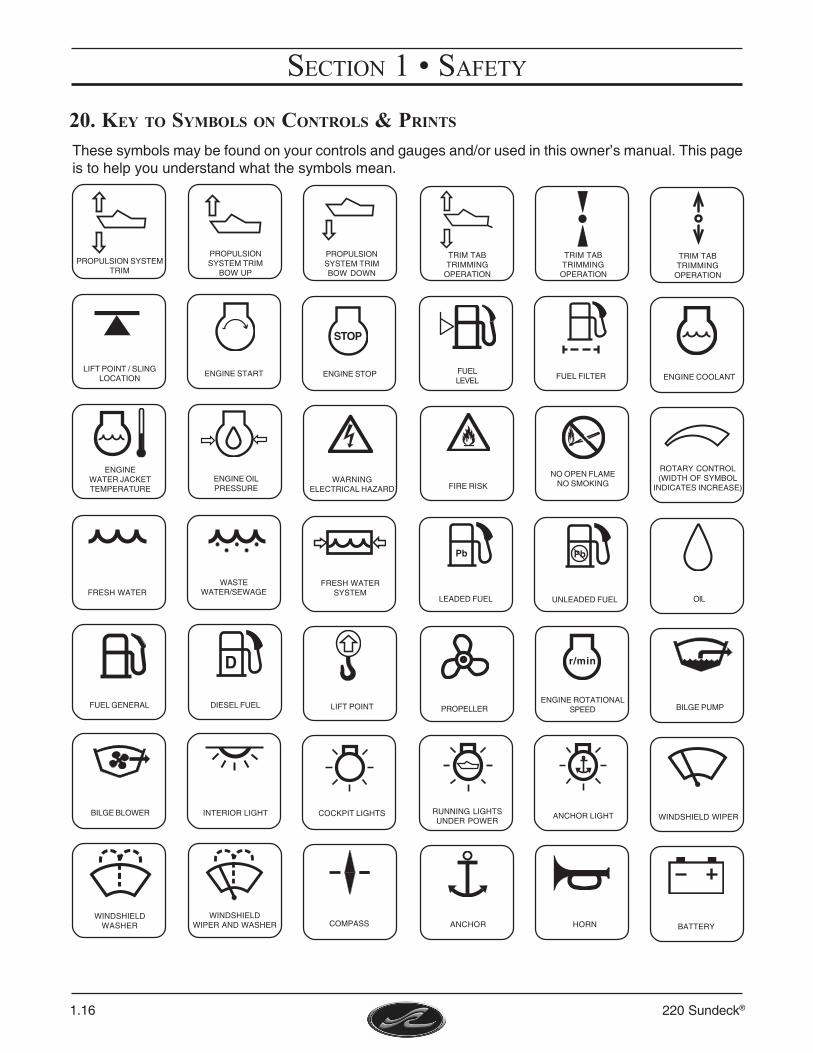
20. KEY TO SYMBOLS ON CONTROLS & PRINTS
These symbols may be found on your controls and gauges and/or used in this owner’s manual. This pageis to help you understand what the symbols mean.
PROPULSION SYSTEMTRIM
PROPULSIONSYSTEM TRIM
BOW UP
PROPULSIONSYSTEM TRIMBOW DOWN
TRIM TABTRIMMING
OPERATION
TRIM TABTRIMMING
OPERATION
TRIM TABTRIMMING
OPERATION
LIFT POINT / SLINGLOCATION
ENGINE START ENGINE STOP FUELLEVEL FUEL FILTER ENGINE COOLANT
ENGINEWATER JACKETTEMPERATURE
ENGINE OILPRESSURE
WARNINGELECTRICAL HAZARD
NO OPEN FLAMENO SMOKINGFIRE RISK
ROTARY CONTROL(WIDTH OF SYMBOL
INDICATES INCREASE)
FRESH WATERLEADED FUEL UNLEADED FUEL
WASTEWATER/SEWAGE
OIL
FUEL GENERAL DIESEL FUEL LIFT POINT BILGE PUMPENGINE ROTATIONAL
SPEED
BILGE BLOWER
PROPELLER
INTERIOR LIGHT RUNNING LIGHTSUNDER POWER WINDSHIELD WIPERANCHOR LIGHT
WINDSHIELDWASHER
WINDSHIELDWIPER AND WASHER COMPASS ANCHOR BATTERYHORN
COCKPIT LIGHTS
FRESH WATERSYSTEM

1.17220 Sundeck®
21. 220 SD 21. 220 SD 21. 220 SD 21. 220 SD 21. 220 SD WWWWWarararararning Laning Laning Laning Laning Label Locabel Locabel Locabel Locabel Locationstionstionstionstions
WARNING LABEL LOCATIONS
(FIG. 1.17.1)
MRP 852525 SR-111
WARNING!USE CAUTION WITH SKIER IN TOW
AS TOW ROPE MAY BACKLASH INTOCOCKPIT WHEN RELEASED
MRP 852533 SR-119A
DANGER!NO SMOKING
GASOLINE VAPORS ARE EXPLOXIVE
NOTICE
GASOLINE RECOMMENDATIONMinimum octane rating of 87 AKI.
Refer to the engine owner’s manual foradditional information.
LEAKING FUEL IS A FIRE AND EXPLOSIONHAZARD, INSPECT SYSTEM REGULARY.EXAMINE FUEL TANKS FOR LEAKS ORCORROSION AT LEAST ANNUALLY.
MRP 852632 SR-151
WARNING!
STAY CLEAR OF MOVING PARTSWHILE ENGINE IS RUNNING.
MRP 852624 SR-149
DANGER!
INSIDE ENGINE BOX
MRP 551689 SR-66
• IN CASE OF FIRE DO NOT OPEN ENGINEBOX OR COMPARTMENT
WARNING
• SHUT DOWN ENGINES, GENERATOR AND BLOWERS
• CONTINUOUSLY DISCHARGE ENTIRE CONTENTS OF HALONOR CO 2 PORTABLE FIRE EXTINGUISHER
THROUGH PORT IMMEDIATELY.
MRP 111287 SR-214
DANGER!TO AVOID RISK OF SERIOUS INJURY OR DEATH
SHUT OFF ENGINE WHEN NEAR SWIMMERSOR PRIOR TO USING SWIM PLATFORM AND
BOARDING LADDER.
BELOW CUSHION
IF SWITCH IS TURNED OFF WHILEENGINE IS RUNNING ALTERNATOR
WILL BE DAMAGED.MRP # 921767 SR-167
CAUTION!
12VDC-15A MAX
MRP # 324756 SR-47MRP 811000 SR-102
DANGER!TRANSOM DOOR MUST BE
CLOSED AND SECURE WHENENGINE IS RUNNING
DO NOT STAND OR WALK ONTHIS AREA SERIOUS INJURYCOULD RESULT.
MRP # 113562 SR-216
DANGER!
UNDER ENGINE HATCH, ABOVE ENGINE
BELOW SHIFT/THROTTLEINSIDE STORAGE COMPARTMENT
ON TRANSOM DOOR
AVOID SERIOUS INJURY OR DEATH FROM CARBON MONOXIDE
EXHAUST FUMES FROM ENGINES CONTAIN CARBON MONOXIDE GASAND MAY COLLECT IN ENCLOSED AREAS
KEEP COCKPIT CABIN AND CABIN AREAS WELL VENTILATED. DO NOTUSE CANVAS, SIDE CURTAINS AND FORWARD VISOR WITHOUT
PROPER VENTILATION.
CO SIDKNESS SYMPTIONS INCLUDE HEADACHE, NAUSEA, AND DIZZINESS. DO NOTMISTAKE FOR SEASICKNESS.
MRP 1369743 SR-246
DANGER! !
SEE OWNER’S MANUAL FOR ADDITIONAL INFORMATION
MAXIMUM CAPACITIES
10 PERSONS OR 1600 LBS.1800 POUNDS, PERSONS, GEAR
LOAD AND CAPACITY • COMPARTMENT VENTILATIONSTEERING, FUEL AND ELECTRICAL SYSTEMSINTERNATIONAL LIGHTS • BASIC FLOATION
MANEUVERABILITY
THIS BOAT COMPLIES WITH U.S. COAST
GUARD SAFETY STANDARDS IN EFFECT ON
THE DATE OF CERTIFICATION
MODEL: 220SD
DESIGN COMPLIANCE WITH NMMA REQUIREMENTS BELOW ISVERIFIED. MFR. RESPONSIBLE FOR PRODUCTION CONTROL
NATIONAL MARINE MANUFACTURERS ASSN.
MANUFACTURER: SEA RAY BOATS, INC.
Tellico, TN
CertifiedN M M A
MRP 722041 SR-87
INDICATIONSOF EXCESSIVE EXPOSURE TO “CO” CONCENTRATIONSMAY INCLUDE NAUSEA, DIZZINESS, HEADACHE AND DROWSINESS.
AVOID RIST OF INJURY OR DEATH, SHUTOFF ENGINE NEAR SWIMMERSOR PRIOR TO USING SWIM PLATFORM SUNPAD OR BOARDING LADDER.
DANGER!
WARNING!AVOID COLLISIONS - Maintain lookout as required by “Rules of the Road”.
Visibility can be limited by high boat trim angles, persons and gear. Such issuesare considered under the control of the operator.
USE CAUTION WITH SKIER IN TOW AS TOW ROPE MAY BACKLASHINTO COCKPIT WHEN RELEASED.
NOTICE: It is recommended that all occupants wear approvedPersonal flotation Devices (PFD’s).
CARBON MONOXIDE CAN BE FATAL. In all gasoline powered boats, engineexhaust systems produce colorless and odorless carbon monoxide gas “CO”
Direct prolonged exposure can result in CO poisoning which may be harmful orFATAL. To prevent excess exposure and reduce the possibility of
accumulations of CO in the boat, the operator should include adequateventilation through utilization of cabin hatches and walk-through windshields
to increase the accumulation of CO in and about the boat and require theoperator’s particular attention:
1. Operation at slow speeds or dead in water.2. Operation with a high bow angle attitude.
3. Utilization of canvas tops, side curtains and back curtains.4. Contributing climatic conditions, such as a head wind.
5. Operation of engines and/or generator in confined spaces or a dockside.6. Any blockage of hull exhaust outlets.
Sea Ray Boats220 SD
MAXIMUM
10 + = 820 kg
C E0609
CIMCI
THIS TAG REPLACES DOMESTIC CERTIFICATION TAG (RIGHT)WHEN BOAT IS ORDERED WITH INTERNATIONAL (CE) OPTION.
VENDOR SUPPLIED
CAUTIONAVOID INJURY.
SECURE GLASS DOOR WHILEUNDERWAY.
!
MRP 1798084CALIFORNIA RESIDENTS ONLY
THE ABOVE WARNING IS ATTACHED TO THE STEERING WHEEL PRIOR TO DELIVERY OF ANY BOATS SOLD IN THE STATE OF CALIFORNIA IN ACCORDANCE WITH CALIFORNIA HEALTH &
SAFETY CODE §§ 25249.5-.13:

220 Sundeck®1.18
220 SD Warning Label Locations220 SD Warning Label Locations220 SD Warning Label Locations220 SD Warning Label Locations220 SD Warning Label Locations
WARNING LABEL LOCATIONS
(FIG. 1.18.1)
Save Our SeasIt is illegal to dump plastic trash anywhere into the ocean or navigablewaters of the United States. Violation of these requirements may resultin civil penalty up to $25,000, a fine of $50,000 and imprisonment for up
to five years.
PLASTIC - Includes but is notlimited to: plastic bags,styrofoam cups and lids,sixpack holders, stirrers, straws,milk jugs, egg cartons, syntheticfishing nets, ropes, lines, andbio or photo degradable plas-tics.
GARBAGE - Means paper,rags, glass, metal, crockery(generated in living spacesaboard the vessel-what we nor-mally call trash), and all kindsof food, maintenance andcargo-associated waste.“Garbage” does not includefresh fish or fish parts, dishwa-ter, and gray water.
DUNNAGE- Material used toblock and brace cargo, and isconsidered a cargo associatedwaste.
DISHWATER- Means the liquidresidue from the manual or au-tomatic washing of dishes andcooking utensils which, havebeen pre-cleaned to the extentthat any food particles adheringto them would not normally in-terfere with the operation of au-tomatic dishwashers.
GRAYWATER - Means drain-age from a dishwasher, shower,laundry, bath, and washbasin,and does not include drainagefrom toilets, urinals, hospitals,and cargo spaces.
(and in U.S. Lakes, Rivers,Bays and Sounds)
PLASTICSDUNNAGE, LINING AND PACKING
MATERIALS THAT FLOATANY GARBAGE EXCEPT DISHWATER/
GRAYWATER/FRESH FISH PARTS
PLASTICSDUNNAGE, LINNING AND PACKING
MATERIALS THAT FLOATANY GARBAGE NOT GROUND TO LESS
THAN ONE SQUARE INCH
PLASTICSDUNNAGE, LINING AND PACKING
MATERIALS THAT FLOAT
PLASTICS
3 TO 12 MILES
INSIDE 3 MILES
12 TO 25 MILES
12 TO 25 MILES

220 Sundeck® 2.1
SECTION 2 • GENERAL BOAT ARRANGEMENT
1. DOCKING/LIFTING/TRAILERING
BOW AND STERN CLEATS: Cleats must not beused for lifting the boat, they are intended fordocking or mooring use only.
BOW AND STERN EYES: The bow eye must beused to haul the boat onto a trailer. The stern eyesmust be used as tie down points for trailering the
Do Not use cleats for lifting.
! CAUTION
CLEAT LOCATIONS(FIG. 2.1.1)
CLEAT CLEAT
CLEAT
CLEAT CLEATCLEAT
CLEAT
BOW AND STERN EYE LOCATIONS(FIG. 2.1.2)
BOW & STERN EYE
STERN EYESTERN EYE
BOW EYE
boat. The bow and stern eyes may be used for shortterm lifting of the boat such as for service. Longterm lifting with the bow and stern eyes may causestress on the fiberglass and gel coat.
For long term storage, use flat, wide belt-type slingsand spreaders long enough to keep pressure fromgunwales. Do not place slings where they may lifton underwater fittings.
Boat motion can be erratic.
You can fall overboard or be injured by hittingsomething in or on the boat.
All persons must be in cockpit area or cabin and beprepared for sudden boat movement.
Use front or bow deck area only during anchoring,mooring or emergencies.
! WARNING
Wet decks are slippery.
You can be seriously injured if you slip and fall.
Wear slip resistant footwear secured to your feet andhold on to rails or boat structure.
! WARNING
2. PASSENGER LOCATIONS
1. When the boat is moving, all passengers mustbe in the cockpit area or in the cabin and mustbe on seating provided or, if standing, holdingon firmly (See Figure 2.2.1).
While the person at the wheel must alertpassengers before any sudden or erratic boatmovement, such as crossing wakes, rapid turns,sudden acceleration or deceleration, etc., anemergency action may be necessary beforepassengers can be warned. All passengersmust be prepared for rapid boat movement andbe able to hold on to prevent loss of balance.
2. When persons are on the working deck area,for anchoring, mooring or in emergencies, theymust be holding on and be positioned so as toprevent falling. In bad weather and/or rough

220 Sundeck®2.2
SECTION 2 • GENERAL BOAT ARRANGEMENT
PASSENGER LOCATIONS(FIG. 2.2.1)
ACCOMODATION DECK(DECK AREA INTENDED FOROCCUPATION DURING NORMALOPERATION)
3. PROPULSION SYSTEM
Your boat is equipped with a stern drive propulsionsystem also known as an inboard-outboard engine(Figure 2.3.2). This type of propulsion system hasthe engine inside the boat secured to the hull’sstringers at the rear end of the hull. The stern driveunit, also called the lower unit because it hangsbelow the hull, is part of the propulsion system thatattaches to the outside of the hull or transom. Thestern drive unit pivots to steer the boat.
Rotating propellers can injure orkill you.
Shut off engine when personsare in water, near boat, on swimplatform or ladder.
! DANGER
Wet decks are slippery.
You can be seriously injured ifyou slip and fall.
Wear slip resistant footwearsecured to your feet and holdon to rails or boat structure.
! WARNING
water, if it is essential to be on deck, personsshould be closely tied to cleats, railingstanchions or other securely fastened boathardware.
3. Engines must be turned off if the boat is nearswimmers or persons are on the swim platformor the swim ladder.
220 Sundeck® 2.3
SECTION 2 • GENERAL BOAT ARRANGEMENT
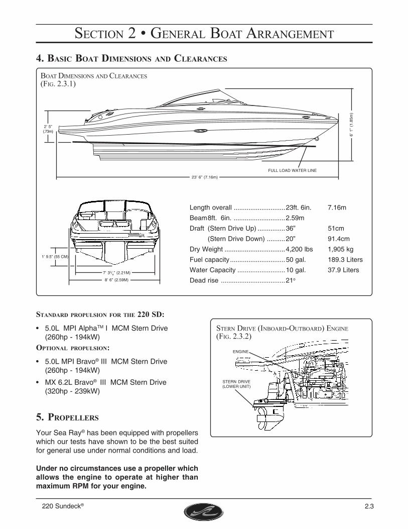
4. BASIC BOAT DIMENSIONS AND CLEARANCES
BOAT DIMENSIONS AND CLEARANCES(FIG. 2.3.1)
23’ 6” (7.16m)
1’ 9.5” (55 CM)
Length overall ............................23ft. 6in. 7.16m
Beam8ft. 6in. ............................2.59m
Draft (Stern Drive Up) ...............36” 51cm
(Stern Drive Down) ..........20” 91.4cm
Dry Weight .................................4,200 lbs 1,905 kg
Fuel capacity ..............................50 gal. 189.3 Liters
Water Capacity ..........................10 gal. 37.9 Liters
Dead rise ...................................21o
2’ 5”(.73m)
STERN DRIVE (INBOARD-OUTBOARD) ENGINE(FIG. 2.3.2)
ENGINE
STERN DRIVE(LOWER UNIT)
FULL LOAD WATER LINE
7’ 35/8” (2.21M)
8’ 6” (2.59M)
6’ 1
” (1
.85m
)
5. PROPELLERS
Your Sea Ray® has been equipped with propellerswhich our tests have shown to be the best suitedfor general use under normal conditions and load.
Under no circumstances use a propeller whichallows the engine to operate at higher thanmaximum RPM for your engine.
STANDARD PROPULSION FOR THE 220 SD:
• 5.0L MPI AlphaTM I MCM Stern Drive(260hp - 194kW)
OPTIONAL PROPULSION:
• 5.0L MPI Bravo® III MCM Stern Drive(260hp - 194kW)
• MX 6.2L Bravo® III MCM Stern Drive(320hp - 239kW)

220 Sundeck®2.4
SECTION 2 • GENERAL BOAT ARRANGEMENT
GENERAL LAYOUT(FIG. 2.4.1)
6. GENERAL DECK LAYOUT
PORT NAVIGATIONLIGHT
STBD NAVIGATIONLIGHT
HORN
BOW SWIM PLATFORM W/LADDER ANDANCHOR STORAGE
CONCEALEDFOLDING SWIM
LADDERSTERN SWIM PLATFORMSKI TOW
BILGE BLOWERVENTILATION
ACCESS PLATE TO FUELTANK SENDING UNIT
COMPANION SEAT WITHFLIP UP THIGH RISE
BOLSTER
PORT LOUNGER & AFTBENCH SEAT
BATTERY SWITCH(OPTION-BELOW CUSHION)
FUEL FILLPLATE
STERNNAVIGATION
LIGHT
FRESH WATERFILL PLATE
AFT PULL-OUTSHOWER
BOW PULL-OUTSHOWER
COCKPIT TABLE
ICE CHEST
BOW SEATINGWITH STORAGE
BELOW
OPENING WALK-THROUGHWINDSHIELD
HEAD COMPARTMENT(PORTABLE HEAD-STANDARD)
PUMPOUT HEAD-OPTION)
WET BAR WITH SINK &STORAGE BELOW
HELM SEAT WITH FLIPUP THIGH RISE BOLSTER
12 VOLT RECEPTACLE (FWDINSIDE SIDEWALL STORAGE)
ENGINE BOX(UNDER CUSHION)
FIRE EXTINGUISHERDISCHARGE PLATE
ACCESS PANEL TO FRESHWATER PUMP & FILTER
TRANSOM DOOR
BOW WALK-THROUGHDOOR
CONTROL STATION
COMPASS (OPTION)
COCKPIT TABLE
SKI STORAGE HATCH

220 Sundeck® 2.5
SECTION 2 • GENERAL BOAT ARRANGEMENT
7. HELM GAUGE AND SWITCH LAYOUT
HELM GAUGES AND SWITCHES(FIG. 2.5.1)
GAUGE PANEL
CLARION STEREO REMOTE
FUELGAUGE
SPEEDOMETER
SYSTEMTACHOMETER
OILPRESSURE
WATERTEMPERATURE
COMPASS(OPTION)
STERN DRIVETRIM GAUGE
STARBOARD SWITCH PANELPORT SWITCH PANEL

220 Sundeck®2.6
SECTION 2 • GENERAL BOAT ARRANGEMENT
8. FUNCTION AND LOCATION OF THROUGH-HULL CUTOUTS
STARBOARD THROUGH-HULL CUTOUTS(FIG. 2.6.1)
PORT THROUGH-HULL CUTOUTS(FIG. 2.6.2)
TRANSOM THROUGH-HULL CUTOUTS(FIG. 2.6.3)
BILGE PUMP
GARBOARD DRAIN
ROPE LOCKERDRAIN
HEAD PUMP-OUTVENT (OPTION)
TRANSDUCERCORSA™ EXHAUST ENTERTAINMENTCENTER SINK DRAIN
STBD DOCKINGLIGHT
PORT DOCKINGLIGHT
CORSA™ EXHAUST
CORSA™ EXHAUST

220 Sundeck® 2.7
SECTION 2 • GENERAL BOAT ARRANGEMENT
GEAR SHIFT AND THROTTLE CONTROL(FIG. 2.7.1)
NEUTRAL (IDLE)
FORWARDREVERSE
IGNITIONSHUTDOWN
SWITCH
FASTER
POWER TRIMSWITCH
FASTER
LANYARDAND CLIP
Cockpit can fill with water if boat is moving forward,when it is put into reverse.
Before shifting into reverse, shift to neutral, wait forboat to stop moving forward, then shift into reverse.
! CAUTION
“THROTTLE ONLY”BUTTON
(PUSH IN AND HOLDWHILE MOVINGSHIFT LEVER
FORWARD)
THROTTLE LOCKBUTTON
B. POWER TRIM UNIT AND GAUGE
The Power Trim allows the operator to raise andlower the stern drive unit while underway to providethe ideal boat angle (in relation to water surface)for a given load and water condition (Figure 2.8.1).
Trimming UP rotates the stern drive and propelleraway from the transom. Trimming DOWN rotatesthe stern drive and propeller closer to the transom.
When the stern drive is trimmed DOWN, the bowof the boat is being forced down. If the trim is in thefull DOWN position when accelerating from idle toplane, the boat will plane faster with less bow rise.Once on plane, the stern drive unit can be trimmedUP slightly. This will raise the bow of the boat slightlyand increase speed. You will need to try smalldifferences in the stern drive position to determinethe trim position you prefer under various conditions.
9. DESCRIPTION OF MAJOR
CONTROLS
A. GEAR SHIFT AND THROTTLE CONTROL
The shift/throttle control unit for the engine activatesby the shifting mechanism and the throttle. Thecontrol must be in neutral position to start yourengine. Moving the lever forward first engages theforward gear. Further forward movement increasesengine speed and propeller RPM, moving the boatfaster. To shift to reverse, bring the control leverback to the neutral position, then move it furtherback to engage the reverse gear. Further rearwardmovement of the lever increases engine speed andpropeller RPM, moving the boat faster in reverse.
Shift/throttle controls are equipped with a “throttleonly” mechanism which allows the shift mechanismto be disengaged from the throttle. This allows thethrottle to be advanced without shifting thetransmission when starting. It may be necessary touse the “throttle only” button in order to pump fuelinto the engine for ease in starting.
The “Throttle Only” mechanism may differ from onestyle gear/throttle unit to another. Refer to your GearShift & Throttle Manual for proper operation of thisfeature.
The throttle control adjusts the RPM of the engineand thus, the rotational speed of the propeller.Regulating the RPM of the engine controls thespeed of the boat.
Forward motion creates forward moving watercalled a “following” wake. If the boat is movingforward and the shift/throttle is moved quickly fromforward to reverse, the boat will stop rapidly andthen move backward. The following wake continuesto move forward and can rise above the transomand flood the boat.
Do not shift into reverse to quickly. Wait for thefollowing wake to dissapate.

220 Sundeck®2.8
SECTION 2 • GENERAL BOAT ARRANGEMENT
EFFECTS OF POWER TRIM(FIG. 2.8.1)
Use transom-mounted power trim switch to tilt fortrailering only. Tilting drive unit into trailering zonewhile underway can damage the drive unit or engine.
! CAUTION
TRANSOM TRAILER TRIM SWITCH (OPTIONAL)(FIG. 2.8.2)
E. IGNITION SHUTDOWN SWITCH
(STANDARD ON SIDE MOUNT CONTROLS)
The purpose of the ignition shutdown switch (Figure2.9.1) is to shut down the engine, if the operatorunintentionally leaves the helm. Situations in whichthis could occur are rough water, bad weather andother adverse boating conditions. In thesesituations, the safety of the boat and its passengersis enhanced by using the ignition shutdown switch,
C. TRAILER SWITCH
The trailer switch (power trim switch) is not to beconfused with the power trim function. The trailerswitch is to be used only when the engine is OFF.
The trailer switch allows the drive unit to be raisedfor trailering, beaching and launching. To operate,press and hold the trailer switch until the drive unitreaches the end of upward travel. The mechanism
that raises the lower unit will stop operating at theend of the upward travel. To bring the drive unitdown into boating position, push the power trimswitch down.
D. TRANSOM TRAILER TRIM SWITCH
(OPTIONAL)
A transom-mounted power trim switch is availablefor the convenience of raising the drive unit to theTRAILERING position while at the rear of the boat.
If you raise the stern drive up to far while you areon plane, you could cause a loss of speed andpower due to condition called propeller “ventilation.”If this happens, there will be a sudden increase inengine RPM and loss of speed. Do not let thiscondition exist. Immediately reduce your engineRPM and trim the outdrive DOWN slightly untilengine slows down and you regain forward speed.
The trim gauge indicates the position of the sterndrive relative to the transom.
REFER TO YOUR ENGINE OPERATOR’SMANUAL FOR PROPER TRIM GAUGE SETTING.
F
DN
UP

220 Sundeck® 2.9
SECTION 2 • GENERAL BOAT ARRANGEMENT
IGNITION SHUTDOWN SWITCH(FIG. 2.9.1)
SHUTDOWN SWITCH
LANYARD AND CLIP
F. ENGINE ALARM SYSTEM (ONLY ON
CERTAIN ENGINES)
The engine Operator’s Manual will tell you if yourengine is equipped with an audible alarm and howto use it.
The alarm indicates a problem with engine watertemperature, oil pressure and/or stern drive oil level.
since the boat will stop when the operator can nolonger control the boat.
However, unintentional engine shutdown may resultin unintentional harm. For example, a passengermay lose balance and fall, or control could be lostduring docking. No specific guidelines can be givenfor switch use. The ultimate decision of when touse an ignition shutdown switch, rests with theoperator or owner.
When the switch is used, the operator must securelyclip the lanyard to their belt or clothing so that if theoperator falls overboard or into the boat, the switchis activated and the engine shuts down.
To reset the ignition shutdown switch after it hasbeen activated, simply reinstall the switch clip abovethe shutoff switch and flip the switch to the UPposition.
SMART CRAFT SYSTEM TACH(FIG. 2.9.2)
10. IMPORTANT GAUGES
A. SMARTCRAFT™ GAUGE SYSTEM
Your boat is equipped with the SmartCraftTM
instrumentation system. The SmartCraftTM systemconsists of a smart tachometer with a displayscreen.
The SmartCraftTM system provides a wide rangeof engine, boat systems and environmentalinformation to the boat operator to help make yourtime on the water more enjoyable by providingaccurate systems information in one convenientlocation, right at the helm. Below is a list of featuresthe SmartCraftTM system offers.
Refer to the SmartCraftTM owner’s manual in theowner’s packet for all SmartCraftTM operatinginstructions.
SOME FEATURES INCLUDE:(Depending on engine type and software version)
SYSTEM TACH DISPLAY SCREEN:• Engine Break-in
• Engine Temperature
• Oil Psi
• Trim and RPM
• Trim and Water Pressure
• Water Pressure
• Battery Voltage
• Engine Hours
• Fuel Flow and Fuel Used
• RPM
• Depth

220 Sundeck®2.10
SECTION 2 • GENERAL BOAT ARRANGEMENT
11. NAVIGATION AND ANCHOR LIGHTS
Navigation lights MUST be on while underway fromsunset to sunrise or in conditions of reducedvisibility. “Underway” means the boat is not dockedor at anchor. Trolling or drifting with engine off isconsidered “underway” and navigation lights mustbe used.
If you are anchored in open water, (where otherboats can approach yours), you must display youranchor light (Figure 2.11.1): a white light that canbe seen from all possible directions, (360 degrees).
Read the “Federal Requirements and Safety Tipsfor Recreational Boats” provided in your kit.
B. TACHOMETER
The tachometer indicates the revolutions per minute(RPM) of the engine. (It does not indicate the speedof the boat.) Your Engine Operator’s Manualindicates the maximum full throttle RPM at whichyour engine should operate. This must not beexceeded or serious engine damage will occur. Thetachometer should also be used to determine themost comfortable and economical cruising RPM.
C. OIL PRESSURE, WATER TEMPERATURE
AND FUEL GAUGES
These gauges function on your boat the same waythey do on your car or truck. You must continuallycheck these gauges visually(See figure 2.5.1) tomake certain there are no engine system problemseven if your boat engine has an alarm system.
D. MAGNETIC COMPASS (OPTIONAL)
If equipped, your compass (See Figure 2.5.1),properly corrected, will indicate magnetic North (nottrue North). A compass must be adjusted by aqualified person. The reason for this is that nearbyinstruments or objects containing magnets orcurrent-carrying electrical wires will influence thecompass reading. This is especially true if you addelectronic devices to the helm station.
After your compass has been professionallyadjusted. You will be given a deviation card or chartindicating the correction to be applied when layingout a compass course or making navigationalcalculations. Keep this correction card or chartat the helm.
NOTE: The compass adjustment is only good forthe equipment arrangement that existed at the timeof the adjustment. If you place different equipmentor remove equipment from the vicinity of thecompass, you cannot rely on the compass reading.The compass must be readjusted by a qualifiedperson after equipment is added or removed fromthe vicinity of the compass.
NOTE: The compass roses shown on navigationalcharts have both true North and magnetic Northdirections superimposed. Make certain you plotcourse compass directions from the magnetic Northcompass rose.
When not in use, the compass should be protectedfrom excessive and prolonged sunlight. If yourcompass becomes sluggish or erratic, it should beserviced by an authorized repair station.
To keep the plexiglass dome free from scratches,remove salt deposits and dust with a damp cloth.An occasional treatment with paste wax will helppreserve the dome surface.
REFER TO OWNER’S MANUAL PACKET FORINSTRUCTIONS AND WARRANTY INFORMATION.

220 Sundeck® 2.11
SECTION 2 • GENERAL BOAT ARRANGEMENT
NAVIGATION AND ANCHOR LIGHTS(FIG. 2.11.1)
RED SIDE LIGHT(VISIBLE 2 NAUTICAL MILES)
GREEN SIDE LIGHT(VISIBLE 2 NAUTICAL MILES)
NAVIGATION AND ANCHOR LIGHT SWITCHES(FIG. 2.11.2)
NAVIGATION LIGHTSWITCH
ANCHOR LIGHTSWITCH
INSERTING THE REMOVABLE STERN ANCHOR LIGHT(FIG. 2.11.3)
SCREW IN TYPECONNECTOR
ANCHOR LIGHTMAST
COMPRESSIONTYPE CONNECTOR
DECK ANCHORLIGHT FITTING
3600 WHITE LIGHT(VISIBLE 2 NAUTICAL MILES)
STARBOARD SWITCH PANEL
220 Sundeck®2.12
SECTION 2 • GENERAL BOAT ARRANGEMENT
THIS PAGE LEFT INTENTIONALLY BLANK
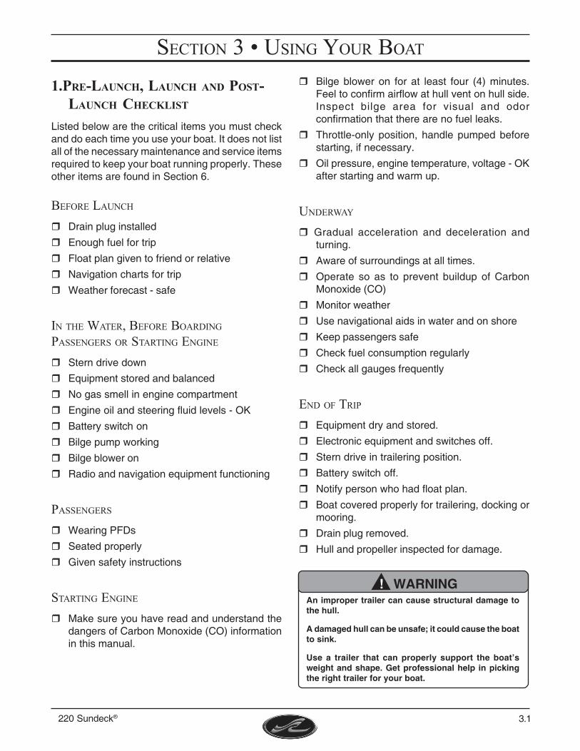
220 Sundeck® 3.1
SECTION 3 • USING YOUR BOAT
1.PRE-LAUNCH, LAUNCH AND POST-
LAUNCH CHECKLIST
Listed below are the critical items you must checkand do each time you use your boat. It does not listall of the necessary maintenance and service itemsrequired to keep your boat running properly. Theseother items are found in Section 6.
BEFORE LAUNCH
� Drain plug installed
� Enough fuel for trip
� Float plan given to friend or relative
� Navigation charts for trip
� Weather forecast - safe
IN THE WATER, BEFORE BOARDING
PASSENGERS OR STARTING ENGINE
� Stern drive down
� Equipment stored and balanced
� No gas smell in engine compartment
� Engine oil and steering fluid levels - OK
� Battery switch on
� Bilge pump working
� Bilge blower on
� Radio and navigation equipment functioning
PASSENGERS
� Wearing PFDs
� Seated properly
� Given safety instructions
STARTING ENGINE
� Make sure you have read and understand thedangers of Carbon Monoxide (CO) informationin this manual.
� Bilge blower on for at least four (4) minutes.Feel to confirm airflow at hull vent on hull side.Inspect bilge area for visual and odorconfirmation that there are no fuel leaks.
� Throttle-only position, handle pumped beforestarting, if necessary.
� Oil pressure, engine temperature, voltage - OKafter starting and warm up.
UNDERWAY
� Gradual acceleration and deceleration andturning.
� Aware of surroundings at all times.
� Operate so as to prevent buildup of CarbonMonoxide (CO)
� Monitor weather
� Use navigational aids in water and on shore
� Keep passengers safe
� Check fuel consumption regularly
� Check all gauges frequently
END OF TRIP
� Equipment dry and stored.
� Electronic equipment and switches off.
� Stern drive in trailering position.
� Battery switch off.
� Notify person who had float plan.
� Boat covered properly for trailering, docking ormooring.
� Drain plug removed.
� Hull and propeller inspected for damage.
An improper trailer can cause structural damage tothe hull.
A damaged hull can be unsafe; it could cause the boatto sink.
Use a trailer that can properly support the boat’sweight and shape. Get professional help in pickingthe right trailer for your boat.
! WARNING
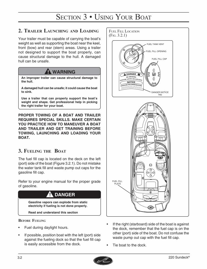
220 Sundeck®3.2
SECTION 3 • USING YOUR BOAT
Gasoline vapors can explode from staticelectricity if fueling is not done properly.
Read and understand this section
! DANGER
FUEL FILL LOCATION(FIG. 3.2.1)
FUEL FILL PLATE
FUEL TANK VENT
FUEL FILL OPENING
DANGER NOTICETAG
FUEL FILL CAP
An improper trailer can cause structural damage tothe hull.
A damaged hull can be unsafe; it could cause the boatto sink.
Use a trailer that can properly support the boat’sweight and shape. Get professional help in pickingthe right trailer for your boat.
! WARNING
3. FUELING THE BOAT
The fuel fill cap is located on the deck on the left(port) side of the boat (Figure 3.2.1). Do not mistakethe water tank fill and waste pump out caps for thegasoline fill cap.
Refer to your engine manual for the proper gradeof gasoline.
BEFORE FUELING
• Fuel during daylight hours.
• If possible, position boat with the left (port) sideagainst the fueling dock so that the fuel fill capis easily accessible from the dock.
• If the right (starboard) side of the boat is againstthe dock, remember that the fuel cap is on theother (port) side of the boat. Do not confuse thewaste pump out cap with the fuel fill cap.
• Tie boat to the dock.
2. TRAILER LAUNCHING AND LOADING
Your trailer must be capable of carrying the boat’sweight as well as supporting the boat near the keel,front (bow) and rear (stern) areas. Using a trailernot designed to support the boat properly, cancause structural damage to the hull. A damagedhull can be unsafe.
PROPER TOWING OF A BOAT AND TRAILERREQUIRES SPECIAL SKILLS. MAKE CERTAINYOU PRACTICE HOW TO MANEUVER A BOATAND TRAILER AND GET TRAINING BEFORETOWING, LAUNCHING AND LOADING YOURBOAT.

220 Sundeck® 3.3
SECTION 3 • USING YOUR BOAT
NO SMOKINGGASOLINE VAPORS ARE EXPLOSIVE
! DANGER
NOTICEGASOLINE RECOMMENDATIONS
Minimum octane rating of 87 AKI.
Refer to the engine owner’s manualfor additional information
Wet decks are slippery.
You can be seriously injured if you slip and fall.
Wear slip-resistant footwear secured to your feet andhold onto rails or boat structure.
! WARNING
4. BOARDING
• DO NOT overload the boat. Refer to CoastGuard capacity plate located near the helm (SeeFigure 1.17.1), and load to less than capacityin adverse conditions.
• Board one person at a time and give assistanceas needed.
• Transfer gear and equipment by handing it froma person on the dock to a person on board. Youcan lose your balance and be injured if youattempt to board while carrying equipment orgear.
• Distribute the weight of equipment andpassengers as evenly as possible to keep theboat balanced.
• Stow gear and equipment so that it is
AFTER FILLING
• DO NOT wash spilled fuel overboard. Wipe upany spill with rags or paper towels and disposeof them properly on shore.
• Open engine compartment and check forgasoline fumes. Leave compartment open untilno odor is apparent. Close compartment.
• If fumes in the engine compartment do notdisappear, do not turn on blower or start engine.Get help from trained and experienced personsbefore using the boat.
• Turn on blower for four minutes, then restartengine.
• Assist passengers back into the boat.
• Shut off engine, bilge blower and all otherelectrical equipment.
• Shut off gas burning appliances (gas stove,etc.).
• Close all hatches, doors and keep enginecompartment closed to prevent gasoline fumesfrom entering the cabin or cockpit area.
• All passengers must leave the boat, as aprecaution.
• There must be no smoking or any flames within20 feet of the boat, before, during and for atleast 5 minutes after fueling is completed.
• Open fuel fill cap and insert hose nozzle intothe fuel fill opening. Fuel fill hose nozzle mustcontact the fuel fill opening BEFORE adding fuelto prevent discharge of static electricity.
FILLING THE TANK
• Check the fill plate label to ensure that fuel isplaced ONLY in the fuel tank. The fuel fill plateis located on the port aft section of your boat(Figure 3.2.1).
• Keep nozzle in contact with fuel fill opening atall times during fueling.
• Listen as tank fills and stop adding gasolinebefore it spills from the vent. Gasoline must haveroom for expansion.

220 Sundeck®3.4
SECTION 3 • USING YOUR BOAT
Gasoline vapors can explode
Before starting the engine, open engine compartmentand check for gasoline smell.
• If you smell gasoline, do not start engine; geteveryone off the boat and get trained help to findand fix the problem.
If there is no gasoline smell, perform checks specifiedby manual, then and only then, close enginecompartment and run blower for at least 4 minutesbefore starting.
! DANGER
7. STARTING THE ENGINES
The engine operation and maintenance manualfurnished with your boat describes pre-start andstarting procedures. We urge you to thoroughly readand understand your engine manual.
Listed below are basic pre-start and startingreminders. These are not a substitute for the enginemanufacturer’s specific recommendations.
Open the engine compartment and check for thesmell of gasoline.
• IF YOU SMELL GASOLINE, get everyone offthe boat, do not operate any electrical switchesor light any matches, lighters, etc. Get trainedhelp to find and fix the problem, before startingthe engine or operating any switches on theboat.
• If you DO NOT smell gasoline.
1. Check all fluid levels and any other necessarychecks as specified in Section 8 and in theengine manual.
2. Check that water level in bilge is minimal. Verifythat the bilge pump is operating by turning thebilge pump switch to MANUAL and listening forthe pump running and check to see that bilgewater is being pumped overboard.
6. PASSENGER INSTRUCTION AND
LOCATION
• Everyone on board must be told about the boat’sbehavior from starting to getting up on plane.
• Before the operator does any high-speedmaneuvers or rapidly accelerates or deceleratesthe boat, passengers must be warned to sit andhold on and must heed the warning.
• The operator may have to make rapid changesin speed and/or direction to avoid a problem,with little or no time for alerting passengers. Itis critical that all passengers be seated in thedesignated seating areas and holding on toprevent falling overboard or getting knockedabout in the boat at all times when the boat isunderway.
5. PERSONAL FLOTATION DEVICES
(PFD’S)
• Operator must instruct all passengers onlocation and use of PFD’s (See Section 1-Safety, for type and usage).
• Children less than sixteen (16) years of age andall non-swimmers, adults as well as children,must wear properly-sized PFDs at all timeswhen aboard.
• ALL passengers should wear PFDs. By the timesomeone falls overboard, it can be to late forthem to put on a PFD and fasten it properly.This is especially true in colder waters, below70oF, where survival time, before hypothermiasets in, is measured in minutes.
• If there are passengers not wearing PFDs, thePFDs must be readily accessible. “Readilyaccessible” means out of the storage bag andunbuckled.
• All throwable flotation devices (cushions, rings,etc.) must be right at hand.
accessible, but everything is to be stored inplaces so as to prevent it from flying about ifthe boat encounters rough water or weather.

220 Sundeck® 3.5
SECTION 3 • USING YOUR BOAT
GUEST
MADE IN U.S.A
�
ON
OFF
FULLY ENGAGED AT DETENTS
STOP ENGINE BEFORE SWITCHINGOFF
(FIG. 3.5.1)
(FIG. 3.5.3)
(FIG. 3.5.2)
(FIG. 3.5.5)
(FIG. 3.5.7)
(FIG. 3.5.6)
(FIG. 3.5.4)
3. Close the enginecompartment and turn onbattery switch locatedunder the aft port seat.
4. Check fuel level. Be sureyou have enough fuel foryour trip. Remember the“1/3 Rule”: Use no morethan 1/3 of your fuel foroutbound trip; use 1/3 ofthe fuel for return trip; keep1/3 for reserve in case ofemergency.
5. Run bilge blowers for atleast 4 minutes beforeattempting to start engine.
Unlike your automobileengine which is naturallyventilated even when it isnot moving, your boatengine compartment (thebilge) does not have sufficient natural ventilationwhen the boat is not moving or moving slowly.That is why the engine compartment must haveforced ventilation, using the bilge blower, toremove potentially explosive gasoline vapors,before the engine is started and when the boatis moving slowly.
Because it may be difficult to remember to turnon the bilge blower every time you slow downthe boat, it is recommended that the bilge blowerrun all the time the engine is running.
6. Place drive unit in fullDOWN/IN position.
7. Put throttle and shiftcontrol lever into neutral;then for a:
COLD ENGINE - pressTHROTTLE ONLY buttonand move shift/throttle lever forward to full open
throttle, then return toabout 1/4 throttle.
WARM ENGINE - PressTHROTTLE ONLY buttonand move shift/throttlelever about 1/4 openthrottle position. Do notpump lever.
FLOODED ENGINE - press THROTTLE ONLYbutton and move shift/throttle lever to full openposition. DO NOT pump lever. When the enginestarts, move shift/throttle lever back rapidly todecrease engine speed to between 1000 and1500 RPM.
8. TO START ENGINE:
Turn ignition keyclockwise, as in a car, andrelease when enginestarts. Do not crankengine for more than a fewseconds if it doesn’t start.Engine may be very coldor flooded; see step 7.
9. After engine starts, reduce speed to between1000 and 1500 RPM and check oil pressure.
10. If oil pressure is correct, letengine warm up to normaltemperature range asspecified in the enginemanual, before shiftinginto forward or reversegear.
IF OIL PRESSURE GOESABOVE OR BELOW OPERATING RANGE,SHUT ENGINE DOWN IMMEDIATELY. GETTRAINED HELP TO FIND AND FIX THEPROBLEM.
E
½
F
PSI
PSI
0
50
100

220 Sundeck®3.6
SECTION 3 • USING YOUR BOAT
(FIG. 3.6.2)
(FIG. 3.6.1)
(FIG. 3.6.4)
(FIG. 3.6.5)
GUEST
MADE IN U.S.A
�
ON
OFF
FULLY ENGAGED AT DETENTS
STOP ENGINE BEFORE SWITCHINGOFF
(FIG. 3.6.6)
Cockpit can fill with water if boat is moving forward,when it is put into reverse.
Before shifting into reverse, shift to neutral, wait forthe boat to stop moving forward, then shift intoreverse.
! CAUTION
(FIG. 3.6.3)
9. STOPPING THE ENGINES
1. Move shift/throttle lever toNEUTRAL and let engineidle for about 5 minutes toallow engine to cool down.
2. Turn ignition key off.
3. If you are leaving the boatfor more than two hours,turn battery switch OFF.
8. SHIFTING TO DRIVE THE BOAT
Bring shift/throttle lever backto neutral position. TheTHROTTLE ONLY button willpop out.
Then move shift/throttle leverrapidly, either forward orreverse, but not very far fromthe neutral position. The driveunit will engage and boat willstart to move slowly in eitherforward or reverse. You candamage the transmission ifyou do not shift quickly fromneutral into gear. Once clear of the dock, mooring,people and/or the no-wake zone and the boat hasbeen shifted into forward gear, move shift/throttlelever forward to desired engine speed.
11. Check water temperatureto ensure temperaturerange remains normal.
IF ENGINE TEMPERATURE GOES ABOVENORMAL RANGE. SHUT DOWN THEENGINE IMMEDIATELY. GET TRAINEDHELP TO FIND AND FIX THE PROBLEM.
250
175
100
˚F

220 Sundeck® 3.7
SECTION 3 • USING YOUR BOAT
POWER STEERINGCYLINDER
POWER STEERING SYSTEM(FIG. 3.7.1)
10. STEERING SYSTEM
The steering system (See figure 3.7.1) is anenclosed push-pull cable that is hydraulicallyassisted (power steering) at the stern drive end.THE CABLE AND ITS CONNECTIONS TO THESTEERING WHEEL AND TO THE OUT DRIVEMUST BE INSPECTED AT LEAST TWICE A YEARBY YOUR SEA RAY DEALER. See section 8 ofthis manual for inspection, service and maintenancerecommendations.
The power steering pump fluid level MUST bechecked every time prior to using the boat. Referto the steering system information in your Owner’sPacket.
POWER STEERING CABLE ROUTING(FIG. 3.7.2)
SHIFT CABLE
STEERING CABLE
THROTTLE CABLE
FLUID RETURNLINE
STEERING WHEEL
STEERINGCABLE FLUID
PRESSURELINE
FLUIDRETURN
LINE
HELM STEERINGRACK
FLUID CHECK& ADD

220 Sundeck®3.8
SECTION 3 • USING YOUR BOAT
THIS PAGE LEFT INTENTIONALLY BLANK

220 Sundeck® 4.1
SECTION 4 • BILGE & UNDERWATER GEAR
1. BILGE
A. FUEL & OIL SPILLAGE
Regulations prohibit discharging fuel or oily wastein navigable waters. Discharge is defined as anyaction which causes a film, sheen or discolorationon the water surface, or causes a sludge or emulsionbeneath the water surface. A common violation isbilge discharge. Use rags or sponges to soak upfuel or oily waste, then dispose of it properly ashore.If there is much fuel or oil in the bilge, contact aknowledgeable marine service to remove it. Neverpump contaminated bilge overboard.
Fill fuel tank less than rated capacity. Allow for fuelexpansion.
B. DRAIN PLUG
The bottom of the engine compartment is called the“bilge”. It is the lowest and inner part of the hull.Water and other liquids will collect here.
After removing your boat from the water, unthreadthe drain plug to drain the bilge.
DRAIN PLUG(FIG. 4.1.1)
C. BILGE PUMP
A bilge pump and float switch are located in thebottom of the bilge. The bilge pump is activatedmanually from the switch panel located on the helmand automatically from the float switch located inthe bilge.
SINKING HAZARD – Ensure the bilge pumps areoperating properly.
! WARNING
Run bilge pumps in the manual position only aslong as necessary to remove water. Running bilgepumps dry can damage the pump motor.
! CAUTION
! DANGER
Install and tighten drain plug before launching boat.
Boat will sink if drain plug is not in place and tight.
BILGE PUMP AND FLOAT SWITCH (BELOW ENGINE)(FIG. 4.1.2)
BILGE PUMP AND BILGE BLOWER SWITCH(FIG. 4.1.3)
TRANSOM HULL
URETHANE CAULK
DRAIN PLUG
GARBOARD DRAIN
AB
C
D
A
B
C
D
FLOAT SWITCH
BILGE PUMP
FWD
FUEL TANK
BILGEBLOWER
BILGEPUMP
PORT SWITCHPANEL
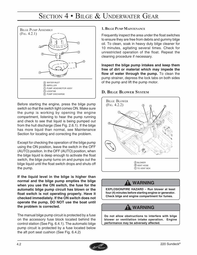
220 Sundeck®4.2
SECTION 4 • BILGE & UNDERWATER GEAR
Before starting the engine, press the bilge pumpswitch so that the switch light comes ON. Make surethe pump is working by opening the enginecompartment, listening to hear the pump runningand check to see that liquid is being pumped outfrom the hull discharge (See Fig. 2.6.1). If the bilgehas more liquid than normal, see MaintenanceSection for locating and correcting the problem.
Except for checking the operation of the bilge pumpusing the ON position, leave the switch in the OFF(AUTO) position. In the OFF (AUTO) position, whenthe bilge liquid is deep enough to activate the floatswitch, the bilge pump turns on and pumps out thebilge liquid until the float switch drops and shuts offthe pump.
If the liquid level in the bilge is higher thannormal and the bilge pump empties the bilgewhen you use the ON switch, the fuse for theautomatic bilge pump circuit has blown or thefloat switch is not operating properly. Have itchecked immediately. If the ON switch does notoperate the pump, DO NOT use the boat untilthe problem is corrected.
The manual bilge pump circuit is protected by a fuseon the accessory fuse block located behind thecontrol station (See Fig. 6.4.1). The automatic bilgepump circuit is protected by a fuse located belowthe aft port seat cushion (See Fig. 6.4.2)
1. BILGE PUMP MAINTENANCE
Frequently inspect the area under the float switchesto ensure they are free from debris and gummy bilgeoil. To clean, soak in heavy duty bilge cleaner for10 minutes, agitating several times. Check forunrestricted operation of the float. Repeat thecleaning procedure if necessary.
Inspect the bilge pump intakes and keep themfree of dirt or material which may impede theflow of water through the pump. To clean thepump strainer, depress the lock tabs on both sidesof the pump and lift the pump motor.
D. BILGE BLOWER SYSTEM
BILGE PUMP ASSEMBLY(FIG. 4.2.1)
BILGE BLOWER(FIG. 4.2.2)
WATER INLET
IMPELLER
PUMP HEAD/MOTOR ASSY
LOCKTAB
PUMP DISCHARGE
AB
C
D
E
A
B
C
D
E
BLOWER
VENT HOSE
TO VENT BOX
AB
C
A
C
BC
B
FWD
EXPLOSION/FIRE HAZARD – Run blower at leastfour (4) minutes before starting engine or generator.Check bilge and engine compartment for fumes.
! WARNING
Do not allow obstructions to interfere with bilgeblower or ventilation intake operation. Engineperformance may be adversely affected.
! WARNING
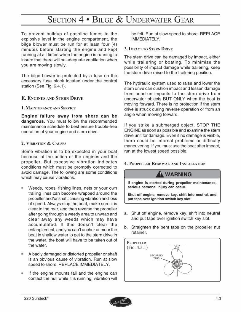
220 Sundeck® 4.3
SECTION 4 • BILGE & UNDERWATER GEAR
To prevent buildup of gasoline fumes to theexplosive level in the engine compartment, thebilge blower must be run for at least four (4)minutes before starting the engine and keptrunning at all times when the engine is running toinsure that there will be adequate ventilation whenyou are moving slowly.
The bilge blower is protected by a fuse on theaccessory fuse block located under the controlstation (See Fig. 6.4.1).
E. ENGINES AND STERN DRIVE
1. MAINTENANCE AND SERVICE
Engine failure away from shore can bedangerous. You must follow the recommendedmaintenance schedule to best ensure trouble-freeoperation of your engine and stern drive.
2. VIBRATION & CAUSES
Some vibration is to be expected in your boatbecause of the action of the engines and thepropeller. But excessive vibration indicatesconditions which must be promptly corrected toavoid damage. The following are some conditionswhich may cause vibrations.
• Weeds, ropes, fishing lines, nets or your owntrailing lines can become wrapped around thepropeller and/or shaft, causing vibration and lossof speed. Always stop the boat, make sure it isclear to the rear, and then reverse the propellerafter going through a weedy area to unwrap andclear away any weeds which may haveaccumulated. If this doesn’t clear theentanglement, and you can’t anchor or moor theboat in shallow water to get to the stern drive inthe water, the boat will have to be taken out ofthe water.
• A badly damaged or distorted propeller or shaftis an obvious cause of vibration. Run at slowspeed to shore. REPLACE IMMEDIATELY.
• If the engine mounts fail and the engine cancontact the hull while it is running, vibration will
be felt. Run at slow speed to shore. REPLACEIMMEDIATELY.
3. IMPACT TO STERN DRIVE
The stern drive can be damaged by impact, eitherwhile trailering or boating. To minimize thepossibility of impact damage while trailering, keepthe stern drive raised to the trailering position.
The hydraulic system used to raise and lower thestern drive can cushion impact and lessen damagefrom head-on impacts to the stern drive fromunderwater objects BUT ONLY when the boat ismoving forward. There is no protection if the sterndrive is struck during reverse operation or from anangle when moving forward.
If you strike a submerged object, STOP THEENGINE as soon as possible and examine the sterndrive unit for damage. Even if no damage is visible,there could be internal problems or difficultymaneuvering. If you must use the boat after impact,run at the lowest speed possible.
If engine is started during propeller maintenance,serious personal injury can occur.
Shut off engine, remove key, shift into neutral, andput tape over ignition switch key slot.
! WARNING
PROPELLER(FIG. 4.3.1)
SECURINGTABS
4. PROPELLER REMOVAL AND INSTALLATION
a. Shut off engine, remove key, shift into neutraland put tape over ignition switch key slot.
b. Straighten the bent tabs on the propeller nutretainer.

220 Sundeck®4.4
SECTION 4 • BILGE & UNDERWATER GEAR
PROPELLER(FIG. 4.4.2)
COAT WITH ANTI-SEIZELUBRICANT
PROPELLER(FIG. 4.4.3)
GEAR CASE
WOOD BLOCK
PROPELLER(FIG. 4.4.4)
SECURINGTABS
PROPELLER(FIG. 4.4.1)
GEAR CASE
WOOD BLOCK
PROPELLER
CONTINUITY WASHER
THRUST HUB
PROPELLER NUT
NUT RETAINER
THRUST WASHER
PROPELLER SHAFT
AB
A
BC
D
E
F
G
D
F
G
E
C
c. Place a block of wood between the gear caseand propeller to stop propeller from rotating andremove propeller nut.
d. Remove the propeller nut retainer, the thrusthub and the continuity washer and put them ina secure place. Pull the propeller straight offthe shaft. Remove the thrust washer that isbehind the propeller. If the propeller is seizedto the shaft and cannot be removed by hand,special tools are needed. Have the propellerremoved by an authorized dealer or trainedmechanic.
e. Coat the propeller shaft with an anti-seizelubricant.
f. Install the thrust washer, propeller, continuitywasher, thrust hub, propeller nut retainer andthe propeller nut onto the shaft.
g. Place a block of wood between the gear caseand the propeller and torque the propeller nutto recommended manufacturer’s specifications.The correct propeller nut torque is given in yourEngine Operator’s Manual in the Owner’sManual Packet.
h. Secure the propeller nut by bending three (3)of the tabs of the propeller nut retainer into thethrust hub grooves.

220 Sundeck® 4.5
SECTION 4 • BILGE & UNDERWATER GEAR
BILGE LAYOUT(FIG. 4.5.1)
F. BILGE LAYOUT
BLOWER
POWER TRIM PUMP
BATTERY (OPTION)
BATTERY
BILGE PUMP
FUEL TANK
ELECTRIC FUEL VALVE
WATER PUMP AND FILTER
WATER TANK
AUTOMATIC FIRE EXTINGUISHER (OPTIONAL)
A
J
I
H
G
F
E
D
C
B
AJ
I
H
G
F
E
D
C
B
H
FWD

220 Sundeck®4.6
SECTION 4 • BILGE & UNDERWATER GEAR
THIS PAGE LEFT INTENTIONALLY BLANK

220 Sundeck® 5.1
SECTION 5 • FUEL SYSTEM
1. FUEL SYSTEM
Section 3 - Using Your Boat contains importantfueling information. Take time to read all the fuelrelated information in the owner’s manual.
The 220 Sundeck® standard gasoline fuel systemconsists of a 50 gallon (189 Liters) fuel tank, fueltank vent, an electric fuel valve, engine fuel supplyline and fuel fill.
The fuel tank vent serves as a pressure/vacuumrelease and safety overflow. The fuel vent is locatedinside the fuel cap on the port side of the hull.Periodically check the vent to assure it is not clogged.
The gasoline engine fuel pick-up at the fuel tankhas an electric fuel valve to prevent fuel fromsiphoning out in the event of fuel line failure.
A. ELECTRIC FUEL VALVE
An electric fuel valve is installed on your boat. Thefuel valve is located in-line on the fuel hose betweenthe fuel tank and the engine or generator. The valveis wired to the ignition switch. When the ignition isturned ON, the valve opens; when the ignition is
turned OFF, the valve closes. The manual overrideknob on the side of the valve should be left in theOFF position at all times.
In the event of an electrical malfunction, the valvecan be opened and closed manually by turning themanual override knob.
FUEL LINE ROUTING(FIG. 5.1.1)
FUEL TANK
FUEL GAUGE SENDER
ELECTRIC FUEL VALVE
FUEL FEED HOSE
FUEL FILL HOSE
FUEL VENT HOSE
FUEL VENT
FUEL FILL
FUEL CAP
DANGER TAG
A
B
D
E
C
E
F
TYPICAL ELECTRIC FUEL VALVE(FIG. 5.1.2)
MANUAL OVERRIDEON/OFF KNOB
A
G
H
J
I
F
G
I
J
H
B
D
CFWD
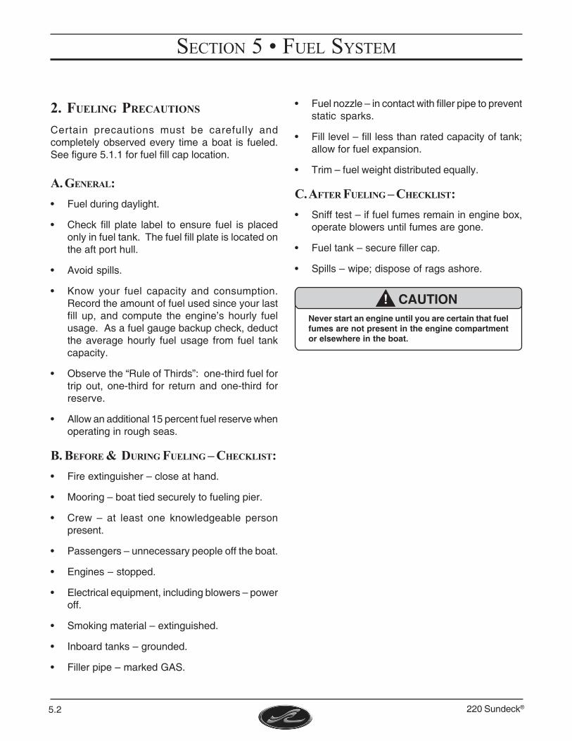
220 Sundeck®5.2
SECTION 5 • FUEL SYSTEM
Never start an engine until you are certain that fuelfumes are not present in the engine compartmentor elsewhere in the boat.
! CAUTION
2. FUELING PRECAUTIONS
Certain precautions must be carefully andcompletely observed every time a boat is fueled.See figure 5.1.1 for fuel fill cap location.
A. GENERAL:
• Fuel during daylight.
• Check fill plate label to ensure fuel is placedonly in fuel tank. The fuel fill plate is located onthe aft port hull.
• Avoid spills.
• Know your fuel capacity and consumption.Record the amount of fuel used since your lastfill up, and compute the engine’s hourly fuelusage. As a fuel gauge backup check, deductthe average hourly fuel usage from fuel tankcapacity.
• Observe the “Rule of Thirds”: one-third fuel fortrip out, one-third for return and one-third forreserve.
• Allow an additional 15 percent fuel reserve whenoperating in rough seas.
B. BEFORE & DURING FUELING – CHECKLIST:
• Fire extinguisher – close at hand.
• Mooring – boat tied securely to fueling pier.
• Crew – at least one knowledgeable personpresent.
• Passengers – unnecessary people off the boat.
• Engines – stopped.
• Electrical equipment, including blowers – poweroff.
• Smoking material – extinguished.
• Inboard tanks – grounded.
• Filler pipe – marked GAS.
• Fuel nozzle – in contact with filler pipe to preventstatic sparks.
• Fill level – fill less than rated capacity of tank;allow for fuel expansion.
• Trim – fuel weight distributed equally.
C. AFTER FUELING – CHECKLIST:
• Sniff test – if fuel fumes remain in engine box,operate blowers until fumes are gone.
• Fuel tank – secure filler cap.
• Spills – wipe; dispose of rags ashore.

220 Sundeck® 6.1
SECTION 6 • ELECTRICAL SYSTEM
1. ELECTRICAL SYSTEM
A. DIRECT CURRENT (DC)
The 12 volt direct current (DC) electrical system(similar to that in your car or truck) derives it’s powerfrom the battery. (Your boat may have two batteriesif you choose that option.) An engine-drivenalternator keeps the battery in a charged condition.The battery voltage is indicated by the voltmeter onthe helm panel. The negative terminal of the batteryis attached to the grounding studs of the engine.
Ask your dealer for a careful analysis of DC powerneeds on your boat. It may be necessary to addbatteries or auxiliary charging methods to supplyadequate power for any additional accessories youwish to add.
BATTERIES
The battery installed in your boat has been selectedfor it’s ability to furnish starting power based onengine starting requirements, as well as it’s abilityto power the DC accessories attached to theelectrical system. Your Engine Owner’s Manualindicates the recommended battery for the engineinstalled in your boat.
To remove the battery cables:
1. Turn off all items drawing power from thebattery.
2. Turn the battery switch to the OFF position(Battery switch is optional equipment on somemodels).
3. Remove the negative cable first, then the positivecable. To replace the cables, first replace thepositive cable, then the negative.
BATTERY MAINTENANCE
• Check the fluid levels in the cells approximatelyevery 4 weeks, and weekly in summer and hotzones.
• The fluid level must be between the lower andupper markings.
• Replenish only with distilled water. Do not usemetal funnel.
• Coat battery terminal clamps with siliconegrease. Keep batteries clean and dry.
Battery life is shortened if it is drained to zero chargebefore recharging. It is recommended that a batterynot be discharged more than 50 percent. If thebattery does become run down, recharge it as soonas posssible.
Running the engine to recharge the battery may notbe effective. The alternator only creates chargingpower at higher engine speeds, so simply idling ortrolling will not generate enough power to rechargethe battery.
If you need to charge a battery, use only a batterycharger designed to charge automotive/marinebatteries. Use charger only when batteries aredisconnected from the boat’s electrical circuit. Followthe charger instructions.
If your boat will not be used for several weeks ormore, remove the batteries from the boat andconnect them to a charger.
DO NOT USE JUMPER CABLES IN THEENGINE COMPARTMENT.
They can cause an explosion from sparks.
! DANGER
A battery will explode if a flame or sparkignites the free hydrogen given off duringcharging.
Never use an open flame or strike sparksin the battery area.
! DANGER
To prevent arcing or damage to the alternator,always disconnect battery cables before doing anywork on the engine’s electrical system.
! CAUTION

220 Sundeck®6.2
SECTION 6 • ELECTRICAL SYSTEM
POSITIVE CABLES
BATTERY CABLE ROUTING (WITH OPTIONAL BATTERY SWITCH)(FIG. 6.2.1)
NEGATIVE CABLES
POSITIVE CABLES
DUAL BATTERY CABLE ROUTING (OPTIONAL) (WITH OPTIONAL BATTERY SWITCH)(FIG. 6.2.2)
NEGATIVE CABLES
BATTERY
BATTERY SWITCH
TO ENGINE STARTER TERMINAL
NEGATIVE TERMINAL
AB
C
A
CD
BATTERY
2ND BATTERY OPTION
BATTERY SWITCH
TO ENGINE STARTER TERMINAL
NEGATIVE TERMINAL
A
B
C
A
B
C
D
D
E
B
D
E
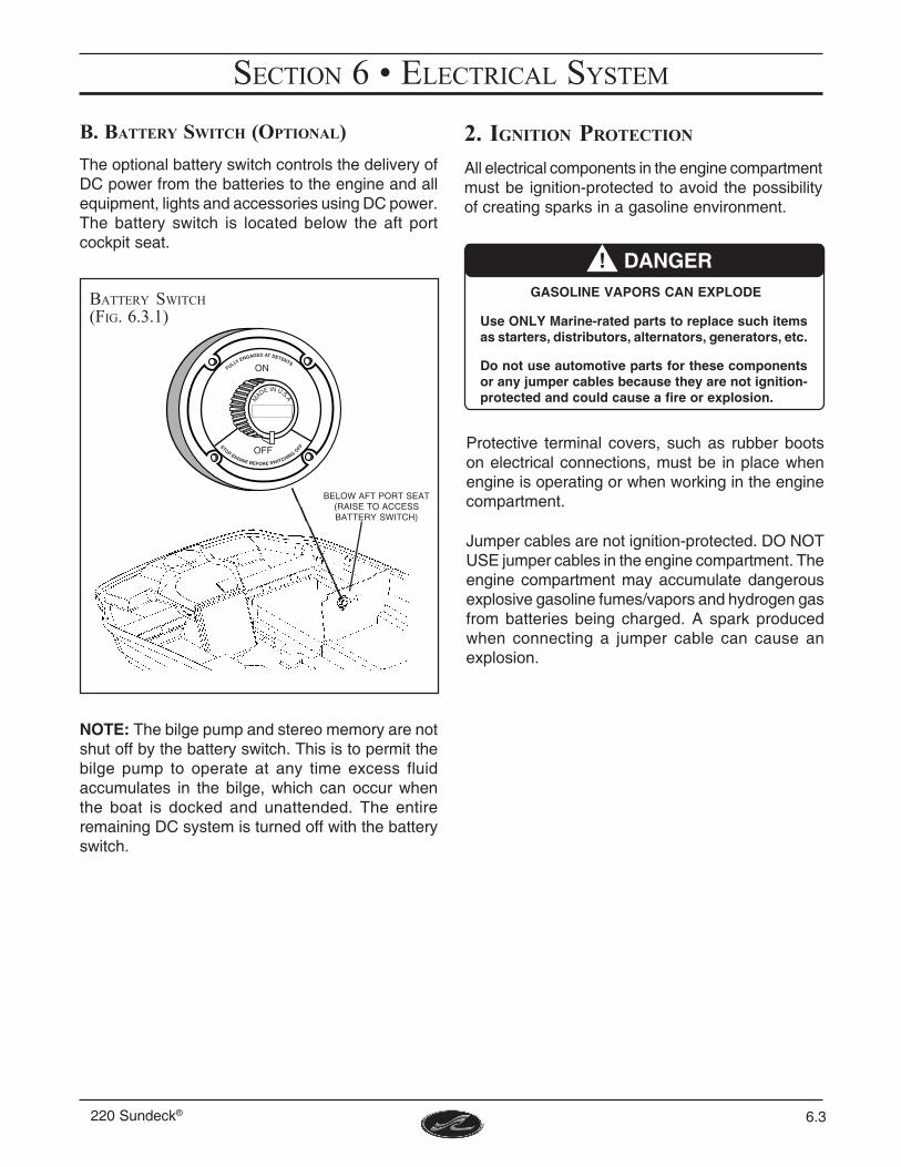
220 Sundeck® 6.3
SECTION 6 • ELECTRICAL SYSTEM
BATTERY SWITCH(FIG. 6.3.1)
GUEST
MADE IN U.S.A
�
ON
OFF
FULLY ENGAGED AT DETENTS
STOP ENGINE BEFORE SWITCHINGOFF
BELOW AFT PORT SEAT(RAISE TO ACCESSBATTERY SWITCH)
GASOLINE VAPORS CAN EXPLODE
! DANGER
Use ONLY Marine-rated parts to replace such itemsas starters, distributors, alternators, generators, etc.
Do not use automotive parts for these componentsor any jumper cables because they are not ignition-protected and could cause a fire or explosion.
2. IGNITION PROTECTION
All electrical components in the engine compartmentmust be ignition-protected to avoid the possibilityof creating sparks in a gasoline environment.
Protective terminal covers, such as rubber bootson electrical connections, must be in place whenengine is operating or when working in the enginecompartment.
Jumper cables are not ignition-protected. DO NOTUSE jumper cables in the engine compartment. Theengine compartment may accumulate dangerousexplosive gasoline fumes/vapors and hydrogen gasfrom batteries being charged. A spark producedwhen connecting a jumper cable can cause anexplosion.
B. BATTERY SWITCH (OPTIONAL)
The optional battery switch controls the delivery ofDC power from the batteries to the engine and allequipment, lights and accessories using DC power.The battery switch is located below the aft portcockpit seat.
NOTE: The bilge pump and stereo memory are notshut off by the battery switch. This is to permit thebilge pump to operate at any time excess fluidaccumulates in the bilge, which can occur whenthe boat is docked and unattended. The entireremaining DC system is turned off with the batteryswitch.
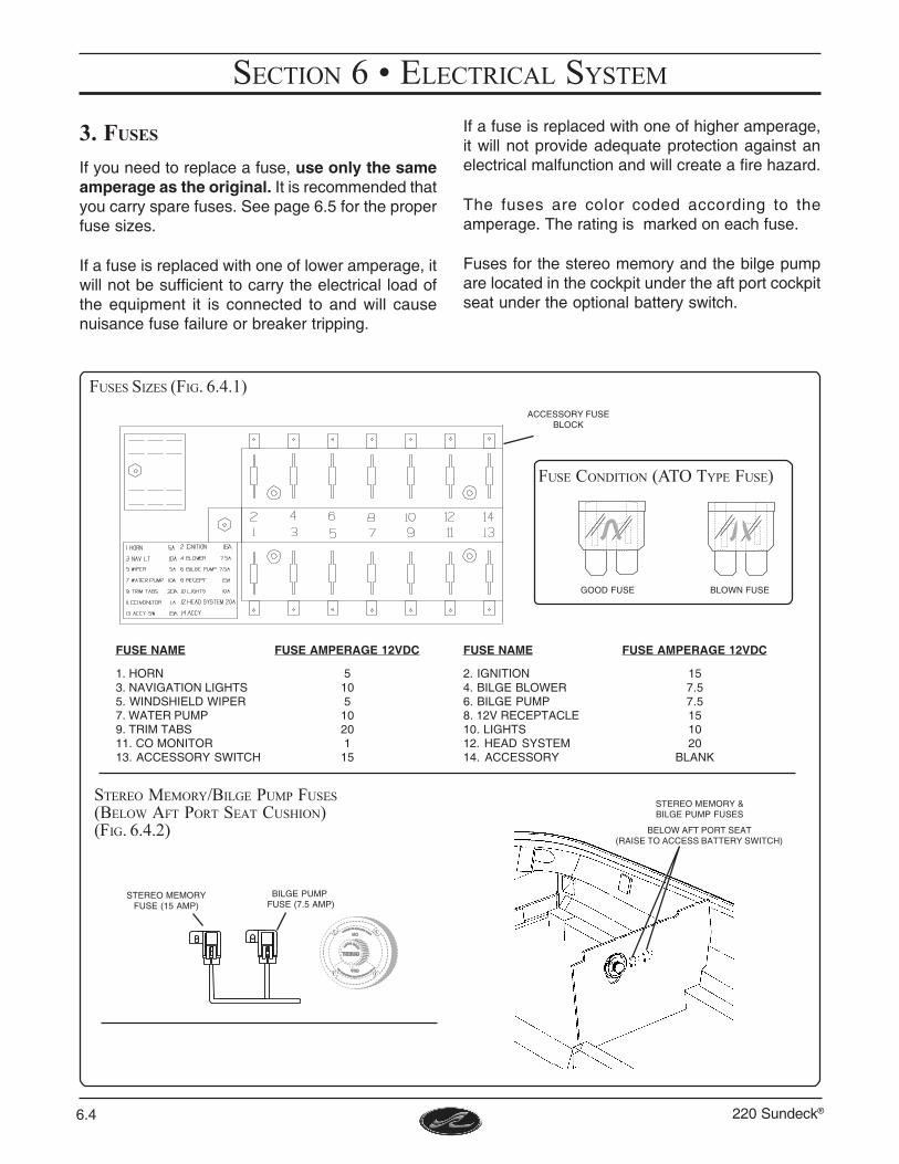
220 Sundeck®6.4
SECTION 6 • ELECTRICAL SYSTEM
ACCESSORY FUSEBLOCK
FUSE NAME FUSE AMPERAGE 12VDC
1. HORN 53. NAVIGATION LIGHTS 105. WINDSHIELD WIPER 57. WATER PUMP 109. TRIM TABS 2011. CO MONITOR 113. ACCESSORY SWITCH 15
FUSES SIZES (FIG. 6.4.1)
3. FUSES
If you need to replace a fuse, use only the sameamperage as the original. It is recommended thatyou carry spare fuses. See page 6.5 for the properfuse sizes.
If a fuse is replaced with one of lower amperage, itwill not be sufficient to carry the electrical load ofthe equipment it is connected to and will causenuisance fuse failure or breaker tripping.
If a fuse is replaced with one of higher amperage,it will not provide adequate protection against anelectrical malfunction and will create a fire hazard.
The fuses are color coded according to theamperage. The rating is marked on each fuse.
Fuses for the stereo memory and the bilge pumpare located in the cockpit under the aft port cockpitseat under the optional battery switch.
STEREO MEMORY/BILGE PUMP FUSES(BELOW AFT PORT SEAT CUSHION)(FIG. 6.4.2)
G�U�E�S�T�M
�A�D�E�I�N�U�.�S�.�A�
��
ON�
OFF�
F�U�L�L�Y�E�N�G�A�G�E�D�A�T�D�E�T�E�N�T�S�
S�T�O�P�E�N�G�I�N�E�B�E�F�O�R�E�S�W�I�T�C�H�I�N�G�O�F�F�
STEREO MEMORYFUSE (15 AMP)
BILGE PUMP FUSE (7.5 AMP)
STEREO MEMORY &BILGE PUMP FUSES
BELOW AFT PORT SEAT(RAISE TO ACCESS BATTERY SWITCH)
FUSE CONDITION (ATO TYPE FUSE)
GOOD FUSE BLOWN FUSE
FUSE NAME FUSE AMPERAGE 12VDC
2. IGNITION 154. BILGE BLOWER 7.56. BILGE PUMP 7.58. 12V RECEPTACLE 1510. LIGHTS 1012. HEAD SYSTEM 2014. ACCESSORY BLANK

220 Sundeck® 6.5
SECTION 6 • ELECTRICAL SYSTEM
12 VOLT RECEPTACLE(INSIDE SIDE PANEL STORAGE) (FIG. 6.5.2)
STBD SIDE PANELSTORAGE
4. LIGHTING
Your boat is equipped with a variety of differentlighting fixtures. Always replace a bulb using thetype and wattage of the original bulb.
5. 12 VOLT ACCESSORY RECEPTACLE
Your boat has a 12 volt accessory receptacle inthe starboard side panel storage area. Thereceptacle is a cigarette lighter style plug that maybe used with any 12 volt accessories using this typeof plug.
12 VOLTRECEPTACLE
6. ELECTROLYTIC CORROSION AND
ZINC ANODES
Electrolytic corrosion of metals on power boats canresult in rapid and serious deterioration of metalparts. You must set a regular schedule and look forthe possibility of electrolytic corrosion (thedeterioration of metals due to dissimilarcharacteristics when placed in salt water). It is yourresponsibility to check for and replace partsdamaged due to electrolytic corrosion.
To minimize electrolytic corrosion of the metals onyour boat, zinc anode plates are provided to protectunderwater hardware. Zinc, being much less “noble”than the copper-based alloys and aluminum usedin underwater fittings, will deteriorate first andprotect the other metals.
Stern drives are fitted with zinc anodes on theirlower units (refer to your Engine Owner’s Manualfor their locations).
LIGHTING(FIG. 6.5.1)
ANCHOR LIGHT
BULB REPLACEMENTAO GE 906
BOW NAV. LIGHT
BULB REPLACEMENTBULB# GE2641L
12V R 10W
COCKPIT LIGHT
BULB REPLACEMENTFUSE TYPE BULB
#12V10WPERKO #70-0
COMPARTMENTLIGHT
BULBREPLACEMENT
BULB#CEC1141

220 Sundeck®6.6
SECTION 6 • ELECTRICAL SYSTEM
DO NOT PAINT BETWEEN THE ZINC AND THE METALIT CONTACTS, AND DO NOT PAINT OVER THE ZINC.
NOTICE
7. ELECTRICAL SCHEMATICS
The following electrical schematics weregenerated by electrical CAD designers at theengineering division for technical reference andservice technicians. Sea Ray® does notrecommend that you attempt to work on the boat’selectrical system yourself. Instead we recommendthat you take your boat to your authorized SeaRay® dealer for service. Sea Ray® reserves theright to change or update the electrical systemon any model at any time without notice to theconsumer and is NOT obligated to make anyupdates to units built prior to changes.
Zinc anodes require replacement about every sixmonths if the boat is operated in salt water. In freshwater, the zinc anodes can be replaced about oncea year.
If the anodes deteriorate more rapidly than this,there is probably a stray current problem within theboat or at the slip or mooring.
If the anodes do not deteriorate, they are notprotecting the other metallic parts of your boat. Thiscan be caused by loose anodes or by low gradezinc or by not having a solid electrical contactbetween the anode and the metal it contacts, or bypaint on the anode.
If the anodes are deteriorating rapidly, or not at all,contact your dealer.

220 Sundeck® 6.7
SECTION 6 • ELECTRICAL SYSTEM
ELECTRICAL SCHEMATICS
WIRE HARNESS(FIG. 6.7.1)
DRAWING NO. 09-875 (1 OF 2) REVISION 2
WIRE HARNESS(FIG. 6.7.2)
DRAWING NO. 09-875 (2 OF 2) REVISION 1

220 Sundeck®6.8
SECTION 6 • ELECTRICAL SYSTEM
THIS PAGE LEFT INTENTIONALLY BLANK

6.9220 Sundeck®
Electrical SchematicsElectrical SchematicsElectrical SchematicsElectrical SchematicsElectrical Schematics
DC WIRING DIAGRAM
(FIG. 6.9.1)
DRAWING NO. 09-603 (1 OF 2) REVISION #2
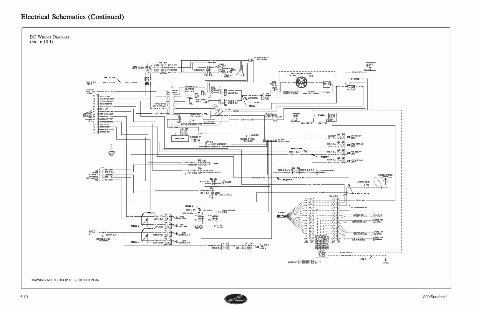
220 Sundeck®6.10
Electrical Schematics (Continued)Electrical Schematics (Continued)Electrical Schematics (Continued)Electrical Schematics (Continued)Electrical Schematics (Continued)
DC WIRING DIAGRAM
(FIG. 6.10.1)
DRAWING NO. 09-603 (2 OF 2) REVISION #4

6.11220 Sundeck®
Electrical Schematics (Continued)Electrical Schematics (Continued)Electrical Schematics (Continued)Electrical Schematics (Continued)Electrical Schematics (Continued)
SATELLITE STEREO SYSTEM
(FIG. 6.11.1)
DRAWING NO. 09-615 Revision #2

220 Sundeck®6.12
Electrical Schematics (Continued)Electrical Schematics (Continued)Electrical Schematics (Continued)Electrical Schematics (Continued)Electrical Schematics (Continued)
SMARTCRAFT™ SYSTEMS DIAGRAM
(FIG. 6.12.1)
DRAWING NO. 09-710 REVISION #2

220 Sundeck® 7.1
SECTION 7 • OPTIONS & ACCESSORIES
FLOORSTORAGE
1. BOAT LAYOUT AND ACCESSORY
LOCATIONS
Figure 7.1.1 and 2.4.1 through 2.6.3 show thelocation and arrangement of the most importantequipment and components on your boat. Using
these drawings, walk through your boat, locate thefeatures shown, and become familiar with theiroperation and maintenance.
ACCESSORIES AND LOCATION(FIG. 7.1.1) BOW SWIM LADDER /
ANCHOR/ROPE LOCKER
GUEST
MADE IN U.S.A
�
ON
OFF
FULLY ENGAGED AT DETENTS
STOP ENGINE BEFORE SWITCHINGOFF
OPTIONALTRANSOM TRIM SWITCH
NAVIGATIONLIGHT
LIFT AFT SEAT TO ACCESS

220 Sundeck®7.2
SECTION 7 • OPTIONS & ACCESSORIES
3. SUNDECK BOW SEATING (OPTIONAL)
Bow seating can be converted into a full areacushioned sun pad by placing the inserts into theopen area of the bow and placing the bow fillercushions in place. The inserts are stowed in thestbd bow storage and the cushions in the port bowstorage compartment.
CONVERTABLE BOW SEATING(FIG.7.2.2)
STBD BOWSTORAGE
PORT BOWSTORAGE
HELM SEAT(FIG.7.2.1)
2. CONTROL STATION SEATING
The control station seat and companion seat featurea thigh-rise cushion which can be lifted out of theway to accomodate standing while maneuvering thevessel for docking and/or anchoring.
BOW FILLERCUSHIONS
BOW FILLERBOARDS
4. COCKPIT TABLE, TABLE SUPPORT &
TRASH CAN STORAGE
The cockpit tables, table supports and the trashcan have dedicated storage locations inside thehelm storage area.
COCKPIT TABLE AND TABLE SUPPORT STORAGE(FIG.7.2.3)
COCKPIT TABLE STORAGEINSIDE HELM STORAGE
COMPARTMENT(BEHIND TABLE SUPPORT
STORAGE)
TABLE SUPPORT & TRASH CANSTORAGE INSIDE HELM
STORAGE COMPARTMENT

220 Sundeck® 7.3
SECTION 7 • OPTIONS & ACCESSORIES
12 VOLT RECEPTACLE(FIG.7.3.1)
STBD COCKPITSIDE PANELSTORAGE
5. 12 VOLT RECEPTACLE
Your Sea Ray® is equipped with a 12 volt accessoryreceptacle located in the starboard hull storage
ENTERTAINMENT SYSTEM(FIG.7.3.2)
AM/FM RADIO, SINGLE CD UNIT
6. ENTERTAINMENT SYSTEM
The entertainment system on the 220 Sundeck®
consists of a 12V AM/FM radio, single CD, satelliteready unit located in the storage area behind thehelm. The system includes four (4) waterproofspeakers, a digital remote control located on thecontrol station and an option digital remote locatedon the transom.
UNDER HELM STORAGE STEREO REMOTE

220 Sundeck®7.4
SECTION 7 • OPTIONS & ACCESSORIES
7. STEERING WHEEL REMOTE CONTROLS
The remote controls on the steering wheel allowthe operator to control the stereo system and theSmartCraft™ System View display without reachingfor the dash.
The SOURCE buttons group controls the stereosystem.
SOURCE button - When pressed and released,powers on the stereo system when it is off.When pressed and released while the systemis on cycles between the system sources fromradio to satellite to CD player to auxiliary inputand back to radio. When pressed and held forone (1) second turns the power off.
UP and DOWN arrow buttons - Control the volume.
LEFT arrow button -
• In radio or satellite mode - When pressed andreleased cycles through the presetchannels. When pressed and held for two(2) seconds in radio mode cycles betweenAM, FM1, FM2 and FM3 bands; in satellitemode cycles between SAT1, SAT2 andSAT3 bands.
• In CD player mode - When pressed andreleased skips to the next CD track. Whenpressed and held for two (2) secondschanges to the next CD in the changer.
STEERING WHEEL REMOTE CONTROLS(FIG. 7.4.1)
SOURCE BUTTONS GROUP(STEREO SYSTEM)
SELECT BUTTONS GROUP(SMARTCRAFT SYSTEM VIEW)
RIGHT arrow button -
• In radio or satellite mode - When pressed andreleased cycles through the presetchannels. When pressed and held has noeffect.
• In CD player mode - When pressed andreleased skips to the previous CD track.When pressed and held has no effect.
The SELECT buttons group controls theSmartCraft™ System View display or System Tachand Speedometer.
For Boats with System View:
SELECT button - When pressed and releasedperforms the same function as the SELECT buttonon the System View. When pressed and held fortwo (2) seconds performs the same function asthe HOME button on the System View.
Direction buttons - When pressed and releasedperform the same functions as the directionbuttons on the System View. When pressedand held have no special function.
For Boats with System Tach and Speedometer:
SELECT button - When pressed and releasedperforms the same function as the MODE buttonon the System Tach.
Left and Right direction buttons - When pressedand released perform the same functions as theTROLL- and TROLL+ buttons on the SystemTACH.
Up direction button - When pressed and releasedselects which system gauge display to control
(Port Tach, Stbd Tach, Speedo). The selectedgauge will display reversed text for two (2)seconds. Not Used on single engine boats withone tachometer and no System Speedometer.
Down direction button - Not used
REFER TO THE SMARTCRAFT AND/ORSYSTEM GAUGES OWNER’S MANUAL FORDETAILED OPERATING INSTRUCTIONS.
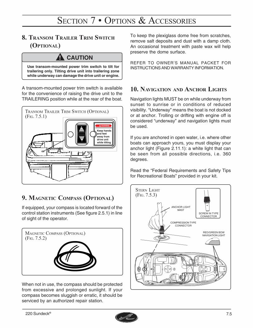
220 Sundeck® 7.5
SECTION 7 • OPTIONS & ACCESSORIES
STERN LIGHT(FIG. 7.5.3)
SCREW IN TYPECONNECTOR
ANCHOR LIGHTMAST
COMPRESSION TYPECONNECTOR
RED/GREEN BOWNAVIGATION LIGHT
10. NAVIGATION AND ANCHOR LIGHTS
Navigation lights MUST be on while underway fromsunset to sunrise or in conditions of reducedvisibility. “Underway” means the boat is not dockedor at anchor. Trolling or drifting with engine off isconsidered “underway” and navigation lights mustbe used.
If you are anchored in open water, i.e. where otherboats can approach yours, you must display youranchor light (Figure 2.11.1): a white light that canbe seen from all possible directions, i.e. 360degrees.
Read the “Federal Requirements and Safety Tipsfor Recreational Boats” provided in your kit.
Use transom-mounted power trim switch to tilt fortrailering only. Tilting drive unit into trailering zonewhile underway can damage the drive unit or engine.
! CAUTION
TRANSOM TRAILER TRIM SWITCH (OPTIONAL)(FIG. 7.5.1)
MAGNETIC COMPASS (OPTIONAL)(FIG. 7.5.2)
9. MAGNETIC COMPASS (OPTIONAL)
If equipped, your compass is located forward of thecontrol station instruments (See figure 2.5.1) in lineof sight of the operator.
When not in use, the compass should be protectedfrom excessive and prolonged sunlight. If yourcompass becomes sluggish or erratic, it should beserviced by an authorized repair station.
8. TRANSOM TRAILER TRIM SWITCH
(OPTIONAL)
A transom-mounted power trim switch is availablefor the convenience of raising the drive unit to theTRAILERING position while at the rear of the boat.
To keep the plexiglass dome free from scratches,remove salt deposits and dust with a damp cloth.An occasional treatment with paste wax will helppreserve the dome surface.
REFER TO OWNER’S MANUAL PACKET FORINSTRUCTIONS AND WARRANTY INFORMATION.

220 Sundeck®7.6
SECTION 7 • OPTIONS & ACCESSORIES
WATER SPORT TOWER (OPTIONAL)(FIG. 7.6.1)
11. WATER SPORT TOWER (OPTIONAL)
If equipped, the water sport tower provides a raisedattach point (ski tow pylon) for the ski rope. Thehigh attach point enables the skier to perform a widevariety of skills not capable with the lower transomattach point (ski tow eye).
The ski tow pylon is intended for use only whentowing a single skier. If you are towing multiple skiersor water toys carrying more than one person useonly the transom mounted ski tow eye.
FIRE EXTINGUISHER DISCHARGE PORT( FIG. 7.6.2)
• In case of fire DO NOT open engine box orcompartment.
• Shut down engine and blowers.
• Continususly discharge entire contents of portablefire extinguisher through port immediately.
! WARNING
12. FIRE EXTINGUISHER PORT
Your boat is equipped with a fire extinguisherdischarge port. In the event of a fire, a fireextinguisher can be inserted through the port anddischarged into the engine compartment withouthaving to open the engine box. Do not open theengine compartment immediately! This feedsoxygen to the fire and flashback could occur.
IF A FIRE OCCURS, IMMEDIATELY SHUTDOWN ALL ENGINES, POWEREDVENTILATION, ELECTRICAL SYSTEMS ANDEXTINGUISH ALL SMOKING MATERIALS. DONOT IMMEDIATELY OPEN THE ENGINECOMPARTMENT!! THIS FEEDS OXYGEN TOTHE FIRE AND FLASHBACK COULD OCCUR.
DO NOT USE TOWER FOR PULLING INFLATABLES.Use water sports tower for single skier/wakeboarderonly. Use ski tow or stern eyes on transom for allother tow behind sports. Heavy loads could collapsetower causing personal injury.
! WARNING
DO NOT USE WATER SPORTS TOWER FOR TOWINGANOTHER BOAT OR BEING TOWED. TOWER COULDCOLLAPSE AND CAUSE INJURY. SEE OWNER’SMANUAL FOR INSTRUCTIONS ON TOWING.
! WARNING
AFT SEATING(ENGINE BOX)
FIRE PORT

220 Sundeck® 7.7
SECTION 7 • OPTIONS & ACCESSORIES
14. AUTOMATIC FIRE EXTINGUISHER
SYSTEM (OPTION)
If equipped the 220 Sundeck® automatic fireextinguisher system is located aft of the engine onthe transom. In the event of a fire, the heat sensitiveautomotic head will release the extinguishant as avapor, totally flooding the area in fire-killingconcentrations. The system indicator light is wiredto the ignition and is turned ON when the ignition isturned ON.
15. WATER SYSTEM
The fresh water system is activated by the FRESHWATER switch on the helm switch panel. The switchmust be ON to operate the sink faucet or cockpitshower.
To begin initial operation:
1. Fill the water tank from a source known toprovide safe, pure drinking water by removingthe cap marked WATER located on the aftstarboard deck and inserting the water hosenozzle in the opening. (Figure 7.8.1). Do notmistake the fuel fill on the aft port side of thedeck for the water tank fill cap.
2. Turn ON the WATER SYSTEM switch.
3. Open the sink faucet to allow any air trapped inthe water line to dissapate.
4. Shut off faucet as flow becomes free of air.Shutting off the faucet will cause the pump toshut off. As long as the water system andbattery switches are on , the pump willautomatically provide water on demand.
WATER PUMP SWITCH(FIG.7.7.3)
FRESH WATERPUMP
SWIM PLATFORM LADDER(FIG. 7.7.1)
AFT LADDER(STOWED)
13. SWIM PLATFORM AND LADDER
The aft swim ladder is located on the stbd side ofthe swim platform. The bow swim ladder is locatedunder the bow hatch. Unfold the ladder and dropinto the water to assist swimmers in boarding thevessel.
BOWLADDER
TO AVOID RISK OF SERIOUS INJURY OR DEATH SHUTOFF ENGINE WHEN NEAR SWIMMERS OR PRIOR TOUSING SWIM PLATFORM AND BOARDING LADDER.
! DANGER
AUTOMATIC FIRE EXTINGUISHER(FIG. 7.7.2)
AUTOMATICFIRE EXTINGUISHER
The indicator light, located on the dash panel,indicates to the helmsman when the unit hasdischarged. Under normal circumstances, whenthe engines are operating, the charge indicator lightis lit. If the unit discharges, the charge light will goout.
STARBOARDSWITCH PANEL

220 Sundeck®7.8
SECTION 7 • OPTIONS & ACCESSORIES
A. SANITIZING THE WATER SYSTEM
If the fresh water system has not been used forsome time, or if you suspect that it has beencontaminated, then it should be sanitized. Yourmarine dealer may have a water treatment additivethat can be used to sanitize the system. Follow theinstructions provided with the additive.
1. Pump the water tank empty. Shut OFF watersystem switch.
2. Determine the capacity of your water tank (yourstandard water tank holds 8 gallons). You willneed approximately one (1) gallon of weakbleach solution for each fifteen (15) gallons oftank capacity.
3. Prepare the proper amount of a weak bleach
FRESH WATER FILL CAP& FIXTURES(FIG.7.8.1)
FRESH WATERFILL CAP
solution by mixing 1/4 cup of unscentedhousehold chlorine bleach per gallon of water.
4. Pour weak bleach solution into the water tank.
Remember, use about one (1) gallon of weakbleach solution for each fifteen (15) gallons oftank capacity.
5. Fill the remainder of the tank with fresh, cleanwater. This will further dilute the weak bleachsolution.
6. Switch ON the water system switch, then turnon the faucets and allow the air to be exhaustedfrom the plumbing system. By doing this, theentire fresh water system will be filled with asanitizing solution.
7. Allow the sanitizing solution to stand in the watersystem for three (3) hours.
8. Pump the water tank empty.
9. Fill the water system completely with fresh,clean water. Turn on the faucet and permit theentire contents of fresh, clean water to runthrough the system. This will flush the sanitizingsolution out of the plumbing.
10. Fill the water system again, with fresh, cleanwater, and turn on the faucet to permit the air todissapate.
Your water system is now sanitized.
B. WINTERIZING THE WATER SYSTEM
For winterizing the water system refer to Section 8,Winterization Checklist For Boats Stored on Land,E. Water System.
C. WATER PUMP AND FILTER
The water pump and filter (Figure 7.9.1) are locatedin the bilge under the hatch in the center cockpit.The filter (Figure 7.9.2) prevents particles fromentering the pump head. The filter should bechecked and cleaned once a season or when flowis restricted.
BOW SHOWER(OPTION)
TRANSOM SHOWER(STANDARD)
WET BAR PULL-OUTSPRAYER
(STANDARD)

220 Sundeck® 7.9
SECTION 7 • OPTIONS & ACCESSORIES
WATER PUMP FILTER(FIG.7.9.2)
BOWL
FILTER SCREEN
O-RING
COVER
WATER PUMP AND FILTER(FIG.7.9.1)
WATER PUMPDISCHARGE
WATER PUMP
WATER PUMPFILTER
WATER PUMPSUCTION
Before servicing the system, turn the WATERSYSTEM switch OFF and open a faucet to releasepressure on the system. To clean the filter, removethe screen and rinse with clean water. Replace,making sure the O-ring is in place when replacingthe cover (Figure 7.9.2).

220 Sundeck®7.10
SECTION 7 • OPTIONS & ACCESSORIES
D. FRESH WATER AND DRAIN LINE ROUTING
WATER LINE ROUTING(FIG.7.10.1)
ROUTE TOGALLEY SINK
WATER TANK
WATERPUMP
WATER LINE
ROUTE TOTRANSOM SHOWER
FILL HOSE
WATERPUMP
WATERTANK
WATERFILTER
FRESH WATERFILL CAP
BOW SHOWER(OPTION)
TRANSOM SHOWER(STANDARD)
WET BAR PULL-OUTSPRAYER
(STANDARD)
WATER TANKFILL HOSE
WATER TANKVENT HOSE
VENT HOSE
WATERFILTER
ROUTE TOBOW SHOWER
ROUTE TOBOW SHOWER
BOW AREA
WATER LINE ROUTING(FIG.7.10.2)

220 Sundeck® 7.11
SECTION 7 • OPTIONS & ACCESSORIES
DRAIN LINE ROUTING(FIG.7.11.1)
COCKPIT DRAINS
ENTERTAINMENTCENTER SINK DRAIN
BILGE PUMPDRAIN
SKI STORAGEHATCH DRAIN
SKISTORAGE

220 Sundeck®7.12
SECTION 7 • OPTIONS & ACCESSORIES
16. CORSATM THRU-HULL EXHAUST
SYSTEM (OPTION)
This boat may be equipped with CorsaTM CaptainsCallTM Exhaust Diverters that provide flexibility withthe thru-hull exhaust system. You can enjoy thebold sound and added performance of an openexhaust on the water while being a “quiet neighbor”in the marina or when noise restrictions areencorced. Exhaust flow can be directed throughthe transom or the prop with the simple flick of aswitch.
CORSATM EXHAUST SYSTEM HOSE ROUTING(VIEW OF STARBOARD ASSEMBLY)(FIG.7.12.2)
STBD SWITCH PANEL
CORSA EXHAUSTSWITCH (OPTION)
CORSATM EXHAUST SYSTEM SWITCH(FIG.7.12.1)
OPERATION
An auxiliary switch is located at the helm to openand close the diverters. When turned on, heavyduty solenoids are activated that pull the valves open(exhaust vents through the transom). When turnedoff or closed, exhaust is vented through the propunder the water.
REFER TO OWNER’S MANUAL PACKET FORINSTRUCTIONS AND WARRANTYINFORMATION.
EXHAUST HOSE
DIVERTERS

220 Sundeck® 7.13
SECTION 7 • OPTIONS & ACCESSORIES
17. TOILET (HEAD) SYSTEM
Several different Toilet (head) systems are availablefor your boat. The Owner’s Manual Packet hasspecific information on the system installed in yourboat. Read that material.
IMPORTANT ENVIRONMENTAL PROTECTIONAGENCY (EPA) INFORMATION
As a general rule, overboard discharge ofsewage from the head into navigable waters isPROHIBITED.
If you have a pump-out head, it can be emptiedat an approved pump-out facility. If not, youmust empty the holding tank in an appropriateonshore facility.
You must check in your boating area for anyother rules and requirements about sewage.
A. PORTABLE SELF-CONTAINED HEAD
The portable self-contained unit has two individualholding tanks. The top tank is fitted with a handpump and holds fresh water and chemicals. Thebottom tank is for holding waste material (Figure7.13.1).
NOTE: Before leaving the dock make sure capson top and bottom tanks are tight. Make sure toptank is filled with chemicals and the bottom tank isempty.
DETAILED OPERATING INSTRUCTIONS ANDWARRANTY INFORMATION ARE PROVIDEDBY THE EQUIPMENT MANUFACTURER ANDCAN BE FOUND IN THE OWNER’S PACKET.
PORTABLE SELF-CONTAINED HEAD(FIG.7.13.1)
FRESH WATER ANDCHEMICAL TANK
WASTE MATERIALHOLDING TANK
B. PUMP-OUT-HEAD (OPTIONAL)
The portable head with dockside pump-out is thesame head as described above, with the additionof a dockside pump-out hose attached to the wastematerial (bottom) tank. The pump-out hose leads tothe waste pump-out opening on the starboard sideof the boat. To empty the holding tank, the servicesof a dockside pump-out station are needed. Followinstructions at the station and make sure the pump-out station hose is inserted into the deck platemarked “Waste” (Figure 7.13.2).
NOTE: Before leaving the dock make sure the capon top tank and hose clamp on bottom tank aretight. Make sure top tank is filled with water andchemicals and the bottom tank is empty.
DETAILED OPERATING INSTRUCTIONS ANDWARRANTY INFORMATION ARE PROVIDED BYTHE EQUIPMENT MANUFACTURER AND CANBE FOUND IN THE OWNER’S PACKET.
PORTABLE HEAD & WASTE PUMP-OUT CAP(FIG.7.13.2)
WASTE MATERIALPUMP-OUT CAP
PORTABLE HEAD

220 Sundeck®7.14
SECTION 7 • OPTIONS & ACCESSORIES
! DANGER
If the cockpit is totally enclosed with canvas coversand curtains while the engine is running or boat ismoving, carbon monoxide will build up and causedeath or permanent injury.
Do not use the rear (aft) curtain or camper top whileengine is running or boat is moving.
18. CANVAS
The Bimini Top or sunshade (optional) should notbe used when the vessel speed exceeds 45 MPH.Damage to the boat or Bimini may occur.
DO NOT have Bimini Top installed when trailering.Damage to boat or Bimini may occur. Use cockpitcover ONLY when trailering.
Attached to the inside of the Bimini Top is aDANGER tag for Carbon Monoxide Gas (CO)buildup and a WARNING tag for limiting speedswhen Bimini Top canvas is installed. The rear (aft)curtain also has a WARNING tag stating “The AftCurtain must not be used while engine is runningor boat is underway”. If your canvas does not havethese tags, they become lost or are unable to beread, contact your dealer for replacement labels.
For your safety, decide which canvas pieces youwant to remove or install before you leave the boatslip or off-load your boat from the trailer into thewater. Removing or installing canvas on the watercan be difficult since rough water or wakes can
cause you or your passengers to lose their balancewhile attempting canvas removal or installation.
For safety and ease of installation and removal ofcanvas, use at least two people. Know whichcanvas piece(s) that you are to install or remove.
The standard canvas set for the 220 Sundeck®
consists of a bimini top with boot and a cockpit cover/tonneau cover.
The following canvas options are available.
Aft Curtain Side CurtainsCanvas Storage Bag Front Curtain
BIMINI TOP & OPTIONAL CANVAS(FIG.7.14.1)
SUNBRELLA®
BIMINI TOP(STANDARD)
AFT CURTAIN(OPTIONAL)
SIDE CURTAINS(OPTIONAL)
FRONT CURTAINS(OPTIONAL)
! DANGER
In rainy weather and/or cold weather, fresh air mustcirculate through boat to avoid carbon monoxidepoisoning.
See Section 1.4, Carbon Monoxide, for more details.
! DANGER
Exhaust fumes from engines contain deadly carbonmonoxide gas (CO). Boats enclosed with canvas orwith poor ventilation are most likely to collect fumes.
CO sickness symptoms include headache, nauseaand dizziness. Do not mistake these symptoms forsea sickness.
Ventilate boat. See Section 1.4, Carbon Monoxide, formore details.
TONNEAU COVER(STANDARD)
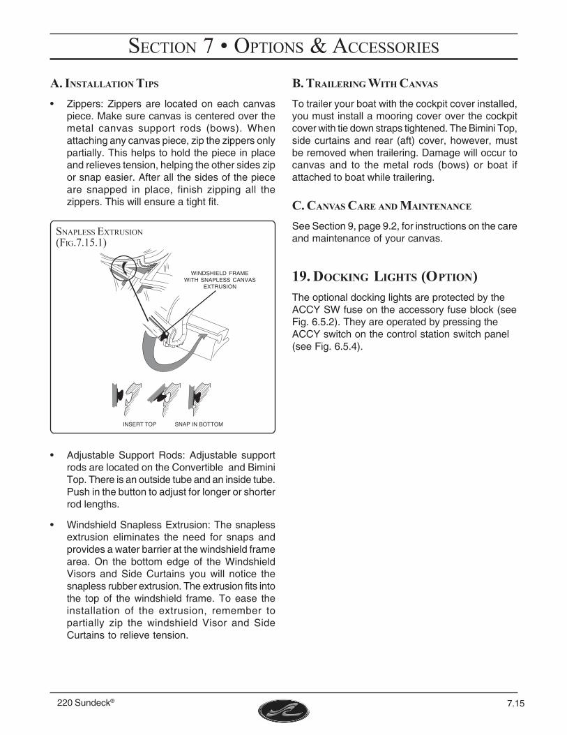
220 Sundeck® 7.15
SECTION 7 • OPTIONS & ACCESSORIES
SNAPLESS EXTRUSION(FIG.7.15.1)
WINDSHIELD FRAMEWITH SNAPLESS CANVAS
EXTRUSION
INSERT TOP SNAP IN BOTTOM
A. INSTALLATION TIPS
• Zippers: Zippers are located on each canvaspiece. Make sure canvas is centered over themetal canvas support rods (bows). Whenattaching any canvas piece, zip the zippers onlypartially. This helps to hold the piece in placeand relieves tension, helping the other sides zipor snap easier. After all the sides of the pieceare snapped in place, finish zipping all thezippers. This will ensure a tight fit.
• Adjustable Support Rods: Adjustable supportrods are located on the Convertible and BiminiTop. There is an outside tube and an inside tube.Push in the button to adjust for longer or shorterrod lengths.
• Windshield Snapless Extrusion: The snaplessextrusion eliminates the need for snaps andprovides a water barrier at the windshield framearea. On the bottom edge of the WindshieldVisors and Side Curtains you will notice thesnapless rubber extrusion. The extrusion fits intothe top of the windshield frame. To ease theinstallation of the extrusion, remember topartially zip the windshield Visor and SideCurtains to relieve tension.
B. TRAILERING WITH CANVAS
To trailer your boat with the cockpit cover installed,you must install a mooring cover over the cockpitcover with tie down straps tightened. The Bimini Top,side curtains and rear (aft) cover, however, mustbe removed when trailering. Damage will occur tocanvas and to the metal rods (bows) or boat ifattached to boat while trailering.
C. CANVAS CARE AND MAINTENANCE
See Section 9, page 9.2, for instructions on the careand maintenance of your canvas.
19. DOCKING LIGHTS (OPTION)
The optional docking lights are protected by theACCY SW fuse on the accessory fuse block (seeFig. 6.5.2). They are operated by pressing theACCY switch on the control station switch panel(see Fig. 6.5.4).

220 Sundeck®7.16
SECTION 7 • OPTIONS & ACCESSORIES
THIS PAGE LEFT INTENTIONALLY BLANK
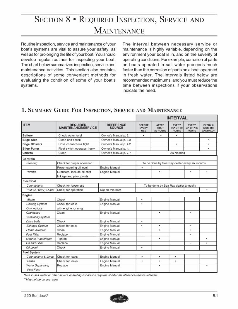
220 Sundeck® 8.1
SECTION 8 • REQUIRED INSPECTION, SERVICE AND
MAINTENANCE
Routine inspection, service and maintenance of yourboat’s systems are vital to assure your safety, aswell as for prolonging the life of your boat. You shoulddevelop regular routines for inspecting your boat.The chart below summarizes inspection, service andmaintenance activities. This section also containsdescriptions of some convenient methods forevaluating the condition of some of your boat’ssystems.
The interval between necessary service ormaintenance is highly variable, depending on theenvironment your boat is in, and on the severity ofoperating conditions. For example, corrosion of partson boats operated in salt water proceeds muchfaster than the corrosion of parts on a boat operatedin fresh water. The intervals listed below arerecommended maximums, and you must reduce thetime between inspections if your observationsindicate the need.
1. SUMMARY GUIDE FOR INSPECTION, SERVICE AND MAINTENANCE
*Use in salt water or other severe operating conditions requires shorter maintenance/service intervals
**May not be on your boat
Fuel System Connections & Lines Check for leaks Engine Manual • • •
Tanks Check for leaks Engine Manual • • •
Water Separating Replace Engine Manual • •
Fuel Filter
Battery Check water level Owner’s Manual p. 6.1 • • •
Bilge Area Clean and check Owner’s Manual p. 8.3 •
Bilge Blowers Hose connections tight Owner’s Manual p. 4.2 • •
Bilge Pump Float switch operates freely Owner’s Manual p. 4.1 •
Canvas Clean Owner’s Manual p. 7.7 As Needed
Controls Steering Check for proper operation To be done by Sea Ray dealer every six months
Power steering oil level Engine Manual •
Throttle Lubricate. Include all shift Engine Manual • • •
linkage and pivot points
Engine
Alarm Check Engine Manual •
Cooling System Check for leaks Engine Manual •
Connections with engine running
Crankcase Clean Engine Manual • •
ventilating system
Drive belts Check Engine Manual •
Exhaust System Check for leaks Engine Manual • • •
Flame Arrestor Clean Engine Manual • •
Fuel Filter Replace Engine Manual •
Mounts (Fasteners) Tighten Engine Manual • •
Oil and Filter Replace Engine Manual • •
Oil Level Check Engine Manual •
ITEM REQUIRED REFERENCE BEFORE AFTER EVERY EVERY EVERY 6MAINTENANCE/SERVICE SOURCE EVERY FIRST 25* OR 50 50* OR 100 MOS. OR
USE 20 HOURS HOURS HOURS ANNUALLY
INTERVAL
Electrical
Connections Check for looseness To be done by Sea Ray dealer annually
**GFCI (120V) Outlet Check for operation Not on this boat •

220 Sundeck®8.2
SECTION 8 • REQUIRED INSPECTION, SERVICE AND
MAINTENANCE
SUMMARY GUIDE FOR INSPECTION, SERVICE AND MAINTENANCE
*Use in salt water or other severe operating conditions requires shorter maintenance/service intervals
**May not be on your boat
Transmission Oil Strainer Screen Clean To be done by Sea Ray dealer annually
Stern Drive
Fluid level Check level Engine Manual •
Fluid Replace Engine Manual •
Propeller Inspect for damage Always after striking object
Seaworthiness
Bilge drain plug Installed and tight Owner’s Manual p. 4.1 •
Hull damage Check for loose, damaged Always after striking object
Stern drive or missing parts
ITEM REQUIRED REFERENCE BEFORE AFTER EVERY EVERY EVERY 6MAINTENANCE/SERVICE SOURCE EVERY FIRST 25* OR 50 50* OR 100 MOS. OR
USE 20 HOURS HOURS HOURS ANNUALLY
INTERVAL
Topside & Supplies Check for loose, damaged Owner’s Manual p. 8.5 •
or missing parts
Anchor rope Check rope for wear •
Zincs Stern drive Check and replace Owner’s Manual p. 6.6 Every 25 hours of operation
needed

220 Sundeck® 8.3
SECTION 8 • REQUIRED INSPECTION, SERVICE AND
MAINTENANCE
2. INSPECTION, SERVICE AND
MAINTENANCE PROTOCOL
A. BILGE AREA
Many of your boat’s systems have critical featureslocated in the bilge area. A thorough and organizedinspection of the bilge area will address many ofthese critical features. For example, engine oil leaksand fuel system leaks will show themselves ascontamination on the surface of the liquid thatremains in the bilge. When you see suchcontamination, you should look for its source.
Once or twice a year, pump the bilge areas dry andremove all loose dirt. Be sure that all the limberholes are open. Limber holes are the openings inthe stringers that allow water to flow from theoutboard areas of the bilge to the bilge sump.
Check the bilge pump float switch by moving itmanually. (Figure 4.1.2) The bilge pump should startwhen the float switch is raised and should stopwhen lowered. If it does not, first replace the fuse,if the pump will still not run replace the float switchbefore using your boat. The float switch should alsomove freely without sticking, if it does not, have itserviced or replaced before boating.
1. OIL
If there is oil contamination, look for leaks in engineoil lines and engine gaskets. If parts of the bilgehave been stained by oil, the stain can be removedusing a bilge cleaner available from your dealer ora marine store.
2. ENGINE
Engine failure or malfunction, when away from
shore, can be dangerous. Make certain you do thefollowing each time you use the boat:
• Wipe off the engine to remove accumulateddust, grease and oil.
• Check all exposed nuts, bolts and screws fortightness.
• Inspect the belts for wear. If they do not requirereplacement, check and adjust the belt tensionaccording to the engine manufacturer’srecommendation.
• Inspect engine wiring, and clean and tighten theterminals on the engine electrical system.
• Clean and lubricate the battery cables.
• Add distilled water to the battery cells as needed.
• Refer to your Engine Operator’s Manual foradditional engine maintenance requirements.
3. FUEL SYSTEM
• Inspect the entire fuel system for evidence ofleakage, including the fuel tank fill lines andvents. Any stain around a joint could be anindication of a leak.
• Test all fittings with a wrench to be sure theyare not loose, but do not forcefully overtightenthe fittings.
• Clean fuel filters and vent screens.
4. WIRING SYSTEM
• Check all wiring for proper support.
• Check all wiring insulation for signs of fraying
DO NOT USE FLAMMABLE SOLVENTS to clean anypart of the bilge.
Fumes can accumulate and can be the source of anexplosion.
! WARNING
Work on electrical wiring can create shock hazardsor sparks.
Always shut off battery switch, breakers and/or pullfuses before checking electrical wiring or connectors.
! WARNING

220 Sundeck®8.4
SECTION 8 • REQUIRED INSPECTION, SERVICE AND
MAINTENANCE
or chafing.
• Check all terminals for corrosion - corrodedterminals and connectors should be replacedor thoroughly cleaned.
• Tighten all terminals securely and spray themwith light marine preservative oil.
5. FITTINGS, HOSES AND CLAMPS
• Inspect the entire bilge area for evidence ofdamage or deterioration. Evidence ofdeterioration will first appear around hull fittings,hoses and clamps.
• Straighten kinked hoses.
• Replace any hose that does not feel pliable.
• Check all hose clamps for tightness andcorrosion. Corroded clamps must be replaced.
• Check the nuts, bolts and screws that retainequipment, hoses, etc. in the bilge for tightnessand corrosion. Corroded fasteners must bereplaced.
B. TOPSIDE AND SUPPLIES
Once a year, you should undertake a thoroughreview of the topside equipment, as well as of thecritical safety supplies on your boat.
• Check cleats, rings, rails, etc. for loose orcorroded fasteners, breaks, sharp edges or otherconditions that could lead to malfunction orunsafe use. Repair or replace as necessary.
• Inspect PFDs (life jackets) for tears anddeterioration.
• Make certain you have enough PFDs on boardfor the maximum number of persons you cancarry.
• Check your first aid kit, making certain it iscomplete and that the items in it have not passedan expiration date.
• Check the signaling equipment and emergencyflares. Make sure all items are within theirexpiration dates.
• Inspect the anchor, mooring and towing lines.Repair or replace as required.
• Check fire extinguishers for full charge.
3. WINTERIZATION CHECKLIST FOR
BOATS STORED ON LAND
A. BOAT STORAGE
• Store boat in a bow high attitude.
• Remove hull drain plug.
• Pour one (1) pint (half-liter) of 50% water/antifreeze mixture in each bilge pump sump..
B. ENGINES
• Flush engines with fresh water.
• Remove engine drain plugs.
REFER TO YOUR ENGINE OPERATOR’S MANUALFOR DETAILED INFORMATION ON PREPARINGTHE ENGINES FOR STORAGE ANDWINTERIZATION.
C. BATTERY
• Remove from boat. Remove the negative (-)cable first, then the positive (+) cable.
• Remove grease and dirt from top surface.
• Grease battery cable terminal bolts.
• Store on wooden pallet or thick plastic in a cooldry place. Do not store on concrete.
• Keep under a trickle charge.
• When placing battery back into service, removeexcess grease from terminals, recharge asnecessary and reinstall in boat.

220 Sundeck® 8.5
SECTION 8 • REQUIRED INSPECTION, SERVICE AND
MAINTENANCE
D. FUEL SYSTEM
GASOLINE:
• Fill fuel tank with gasoline and the recommendedamount of stabilizer and conditioner such as“Stabil®”.
• Run engine(s) for ten minutes to ensure that allgasoline in the carburetor and fuel lines aretreated.
DETAILED WINTERIZING, OPERATING INSTRUCTIONSAND WARRANTY INFORMATION ARE PROVIDED BYTHE EQUIPMENT MANUFACTURER AND CAN BEFOUND IN THE OWNER’S PACKET.
4. FITTING OUT AFTER STORAGE
A. FUEL SYSTEM
Check the entire fuel system for loose connections,worn hoses, leaks, etc. and repair. This is a primarysafety precaution.
Check fuel lines for damage and make sure thatthey do not come in contact with any moving parts.
B. BATTERY
Before installing the batteries, clean the terminalposts with a wire brush or steel wool and then attachthe cables. After the cable clamps are tightened,smear the post and clamps with vaseline or greaseto exclude air and acid. Do not apply grease beforeattaching and tightening the terminal clamps.Examine all wiring.
C. MISCELLANEOUS
• Check all thru-hull fittings for unobstructed waterpassage. Be alert for any deteriorated hosesand/or fittings below the water line which mightfail in service and admit water.
• Test the navigation lights.
• Check all wiring for loose connections.
• Check all switches and equipment for properoperation.
• Check bilge blowers for proper operation. TurnON blowers and place hand over hull blower ventto make sure air is coming from vent.
• Anchor lines and gear should be inspected andreplaced if necessary.
• Make sure the hull drain plug is in place andtight.
• Clean bilge thoroughly if it was not done atlay-up.
• Check all engine fluid levels.
• Check fuel lines for damage and/or leaks. Makesure that they do not come into contact withmoving parts.
5. SECURITY CONSIDERATIONS
Be conscious of the security of your boat.Always remove the keys from the ignition, lockhatches, lock the cabin door, remove and stowany removable electronic gear (fishfinders,LORAN, etc.) and personal gear (fishing poles,etc.) normally left aboard your boat.
6. POWER STEERING SYSTEM
MAINTENANCE
• Lubricate the control valve on the power steeringcylinder through the grease fitting withmultipurpose lubricant until grease appearsaround the rubber boot.
• Coat power assist steering output shaft andexposed steering cable end with appropriatelubricant.
• Lubricate cable end guide pivot point with SAE30W engine oil.
Do not overfill. Filling a tank until the fuel flowsfrom vents is dangerous. Allow room for expansion.
! CAUTION

220 Sundeck®8.6
SECTION 8 • REQUIRED INSPECTION, SERVICE AND
MAINTENANCE
• Check power steering fluid level in the powersteering pump reservoir.
• Inspect all hydraulic hoses for leaks. Keephoses from rubbing on moving parts and fromcontact with hot engine parts.
• Check all fittings, clamps and bolts for tightnessevery month.
• Check power steering pump drive belt for wearand proper tension every month. Do notovertighten belt. This can cause bearing failure.
REFER TO THE ENGINE OPERATOR’S MANUAL FORPROPER FLUID LEVELS AND LUBRICANTS.
Sea Ray® recommends that all repairs and/orreplacements to steering systems be made byqualified dealers authorized by manufacturer of thesteering system of your boat.
DETAILED OPERATING INSTRUCTIONS ANDWARRANTY INFORMATION ARE PROVIDED BYTHE EQUIPMENT MANUFACTURER AND CANBE FOUND IN THE OWNER’S PACKET.
POWER STEERING SYSTEM(FIG. 8.6.1)
POWER STEERINGCYLINDER
STEERINGWHEEL
CHECK & ADDFLUID HERE
FLUIDRETURN LINE
STEERINGCABLE
FLUIDPRESSURE
LINE
FLUIDRETURN
LINE
HELMSTEERING RACK
7. ENGINE OIL CHANGE SYSTEM
Your Sport Boat is equipped with the oil changesystem that allows used oil to be drained out thetransom through hose that pulls out of the transomdrain plug hole.
To Operate:
1. Remove oil fill cap. (To allow ventilation)
2. Remove hull drain plug on transom and pull oildrain hose out of hole.
3. Have enough empty containers at hand to holdall of the used oil. Remove plug in the end ofthe hose. Let oil drain into container(s).
4. When all of the used oil has drained out of theengine reinstall the plug into the hose. Push oildrain hose back into hull and reinstall hull drainplug.
5. Follow oil change instructions provided by theengine manufacturer.
REFER TO THE ENGINE OWNER’S MANUALFOR INSTRUCTIONS AND WARRANTYINFORMATION.
GARBOARD DRAIN PLUG(ALSO USED FOR ENGINE OIL
DRAIN HOSE)
OIL CHANGE PLUGS / GARBOARD DRAIN PLUGS(FIG. 8.6.2)

220 Sundeck® 9.1
SECTION 9 • CARE & REFINISHING
Your new boat has been designed to provide youwith years of enjoyment and satisfaction. In orderto maintain the factory new appearance of your boat,we recommend the use of 3M™ Marine's one stepMaintenance and Reconditioning Products designedspecifically for pleasure boats. Following properfiberglass maintenance guidelines will help maintainyour boat's performance, value, and enjoyment.
1. PAINT CLEANING AGENTS & OTHER
SUBSTANCES
Do not use products containing chlorine,phosphates, perfumes and non-degradableingredients. Consult your marine dealer regardingenvironmental regulations before painting the hull.Fumes can last for hours, and chemical ingredientscan harm people, property and the environment.Common household cleaning agents may causehazardous reactions. Read and understanddirections on all paint, cleaning and polishingmaterials before using.
2. FIBERGLASS & GELCOAT
The fiberglass hull, deck and some interior partsconsist of a molded shell and exterior gelcoat. Thegelcoat is the outer surface, often colored, thatpresents the shiny smooth appearance associatedwith fiberglass products. This gelcoat surface ispainted or taped in some areas for styling purposes.
Wash the gelcoat and fiberglass regularly with clean,fresh water. Wax gelcoated surfaces to maintain the
EXPLOSION/FIRE HAZARD
Care and refinishing materials may containingredients that are flammable or explosive. Do notuse such materials in the bilge
Shut off electrical power and ventilate when usingsuch materials anywhere on the boat or in thecabin.
Do not create sparks or use lighted materials.
! WARNING
luster. In northern climates, a waxing at the startand end of the boating season may suffice. Insouthern climates, an application of wax every threemonths will be required for adequate protection.
REFER TO THE “3M® ONE STEP MAINTENANCE ANDRECONDITIONING PRODUCTS” PAMPHLET IN YOUROWNER’S MANUAL PACKET FOR INSTRUCTIONSAND WARRANTY INFORMATION.
3. STAINS & SCRATCHES
Although gelcoat and painted surfaces are resistantto deep stains, a need for cleaning will occasionallyarise. But, the use of some common cleaning agentswill permanently discolor or otherwise damage thefinish on your boat.
• Do not use abrasive porcelain-cleaning powders.These are too abrasive and contain chlorine andammonia, either of which will permanentlydiscolor gelcoat and paint.
• Never use nail polish remover (acetone) or anyketone solvents.
• Use diluted household detergents to removesurface soil and stains. Before using a givenbrand, check to make sure it contains no chlorineor ammonia.
• Alcohol can be used to remove difficult stains.But it must be promptly washed off with milddetergent and water.
• Minor scratches and deeper stains that do notpenetrate the gelcoat may be removed by lightsanding and buffing.
Gelcoat surfaces are slippery when wet.
Always wear non-slip footwear securely fastened toyour feet and hold on to rails or the boat structrue.
! WARNING
Waxed surfaces are slippery.
Do not wax areas that are usually walked on.
! WARNING

220 Sundeck®9.2
SECTION 9 • CARE & REFINISHING
4. PERMANENTLY MOORED OR
DOCKED BOATS
If permanently moored in salt water or freshwater, your boat will collect marine growth onits bottom. This will detract from the boat’sbeauty and greatly affect its performance. Thereare two methods of preventing this:
• Periodically haul the boat out of the waterand scrub the bottom with a bristle brushand a solution of soap and water.
• Paint the hull below the waterline with agood grade of antifouling paint. DO NOTpaint the engine drive surfaces.
NOTE: There are EPA regulations regardingbottom paint application. Consult your Sea Ray®
dealer for proper application methods.
5. CARE FOR BOTTOM PAINT
From time to time a slight algae or slime formson all vessels. The bottom painted portion ofthe hull can be wiped off with a coarse turkishtowel or a piece of old rug while the boat is inthe water. Do not use a stiff or abrasive materialto clean the bottom paint.
The bottom paint should be inspected annually. Ifit needs repainting consult your Sea Ray® dealer.
6. TOPSIDE AREAS
A. STAINLESS STEEL AND ALLOY FITTINGS
Stainless steel and alloy fittings should be cleanedwith soap and water or household glass cleaner.Remove rust spots as soon as possible with a brass,silver or chrome cleaner. Irreversible pitting willdevelop under rust that remains for any period oftime. Never use an abrasive like sandpaper or steelwool on stainless. These may actually cause rust.To help protect the stainless, we recommend theuse of a good car wax.
B. SALT CRYSTALS
When instruments are exposed to a saltwaterenvironment, salt crystals may form on the bezeland the plastic covers. These salt crystals shouldbe removed with a soft, damp cloth; never useabrasives or rough, dirty cloths to wipe plastic parts.Mild household detergents or plastic cleaners canbe used to keep the instruments bright and clean.
REFER TO THE OWNER'S MANUAL PACKET FORINSTRUCTIONS AND WARRANTY INFORMATION.
7. ACRYLIC PLASTIC SHEETING
(PLASTIC GLASS)
Never use a dry cloth or duster or glass cleaningsolutions on acrylic.
To clean acrylic, first flood it with water to wash offas much dirt as possible. Next, use your bare hand,with plenty of water, to feel and dislodge any cakeddirt or mud. A soft, grit-free cloth may then be usedwith a nonabrasive soap or detergent. A soft sponge,kept clean for this purpose, is excellent. Blot drywith a clean damp chamois.
Grease and oil may be removed from acrylic withkerosene, hexane, white (not aviation or ethyl)gasoline or aliphatic naphtha (no aromatic content).
Do not use solvents such as acetone, siliconespray, benzine, carbon tetrachloride, fireextinguisher fluid, dry cleaning fluid or lacquerthinner on acrylic, since they attack the surface.
Remove fine scratches with fine automotive acrylicrubbing and polishing compounds.
8. CANVAS AND CLEAR VINYL
Do not fold or store any of the canvas pieces whilewet. All canvas should be rolled or folded when dry andstored in a clean, dry place. For clear vinyl pieces, therecommended methods for storage are rolling or laying

220 Sundeck® 9.3
SECTION 9 • CARE & REFINISHING
down flat. The clear vinyl should never be folded orcreased as cracking will result. To protect the clear vinylfrom rubbing against itself while rolled or stored flat,place a piece of very soft, nonabrasive cloth betweenthe pieces. If the surface of the clear vinyl becomesscratched, the canvas manufacturer has provided acanvas care sheet located in your Owner’s ManualPacket. When storing the rear (aft) curtain, fold thecanvas over the clear vinyl window (do not fold clearvinyl), then roll or store flat.
The fabric should be cleaned regularly before substancessuch as dirt, pollen, etc. are allowed to accumulate onand become embedded in the fabric. The fabric can becleaned without being removed from the installation.Simply brush off any loose dirt, particles, etc.; hose downand clean with a mild solution of a natural soap inlukewarm water (no more than 100oF, 38oC); rinsethoroughly to remove soap. DO NOT USEDETERGENTS. Allow to completely dry.
Wash and clean vinyl windows with a warm soapsolution. Use a soft cloth or sponge and do not scratchthe surface.
If you have stubborn cleaning cases, call your dealer forproper procedures. Do not try your own cleaningprocedures as they may permanently damage thecanvas.
After each use, especially in salt water areas, rinse thecanvas completely with fresh cold water. Then let thecanvas dry completely before stowing.
All metal components of the canvas should be rinsedwith fresh cold water and exposed components wipeddry to maintain appearance and working order.
9. EXTERIOR UPHOLSTERY FABRIC
Exterior fabrics should be cleaned with a sponge or verysoft scrub brush and a mild soap and warm watersolution. After scrubbing, rinse with plenty of cold, cleanwater and allow the fabric to air dry in a well ventilatedplace, preferrably away from direct sunlight.
Mildew can occur if your boat does not have adequateventilation. Heat alone will not prevent mildew; you mustalso provide for fresh air circulation.
REFER TO THE OWNER'S MANUAL PACKET FORINSTRUCTIONS AND WARRANTY INFORMATION.