SD3-60 AIRCRAFT MAINTENANCE MANUAL 30.pdf30-11-01 Jun 30/01 EFFECTIVITY: All Page 201 z SD3-60...
102
Jun 30/01 30-00-00 Page 1 EFFECTIVITY: All z SD3-60 AIRCRAFT MAINTENANCE MANUAL AMM 30-00-00 ICE AND RAIN PROTECTION - GENERAL 1. General Ice and rain protection for the aircraft on the ground is provided by protective covers, described in Chapter 10, Parking and Mooring, and by techniques described in Cold Weather Protection in Chapter 12, Servicing. Operationally the aircraft is protected by the following systems: - Aerofoil de-icing. Refer to 30-11-00, pb1. - Engine air intake anti-icing. Refer to 30-20-00, pb1. - Pitot and static anti-icing. Refer to 30-31-00, pb1. - Windshield ice and rain protection. Refer to 30-40-00, pb1. - Five Bade Propeller anti-icing. Refer to 30-61-00, pb1. - Six Blade Propeller anti-icing. Refer to 30-62-00, pb1. - Ice detection system. Refer to 30-80-00, pb1. Flight compartment side window de-misting is covered in Chapter 21, Air Conditioning.
Transcript of SD3-60 AIRCRAFT MAINTENANCE MANUAL 30.pdf30-11-01 Jun 30/01 EFFECTIVITY: All Page 201 z SD3-60...
Jun 30/0130-00-00 Page 1EFFECTIVITY: All
zSD3-60 AIRCRAFT MAINTENANCE MANUAL
AMM30-00-00 2.0.0.0ICE AND RAIN PROTECTION - GENERAL
1. General
Ice and rain protection for the aircraft on the ground is provided by protective covers, described in Chapter 10, Parking and Mooring, and by techniques described in Cold Weather Protection in Chapter 12, Servicing.
Operationally the aircraft is protected by the following systems:
- Aerofoil de-icing. Refer to 30-11-00, pb1.- Engine air intake anti-icing. Refer to 30-20-00, pb1.- Pitot and static anti-icing. Refer to 30-31-00, pb1.- Windshield ice and rain protection. Refer to 30-40-00, pb1.- Five Bade Propeller anti-icing. Refer to 30-61-00, pb1.- Six Blade Propeller anti-icing. Refer to 30-62-00, pb1.- Ice detection system. Refer to 30-80-00, pb1.
Flight compartment side window de-misting is covered in Chapter 21, Air Conditioning.
Apr 24/0330-11-00 Page 1EFFECTIVITY: All
zSD3-60 AIRCRAFT MAINTENANCE MANUAL
AMM30-11-00 3.0.0.0AEROFOIL DE-ICING - DESCRIPTION & OPERATION
1. Description
A. General
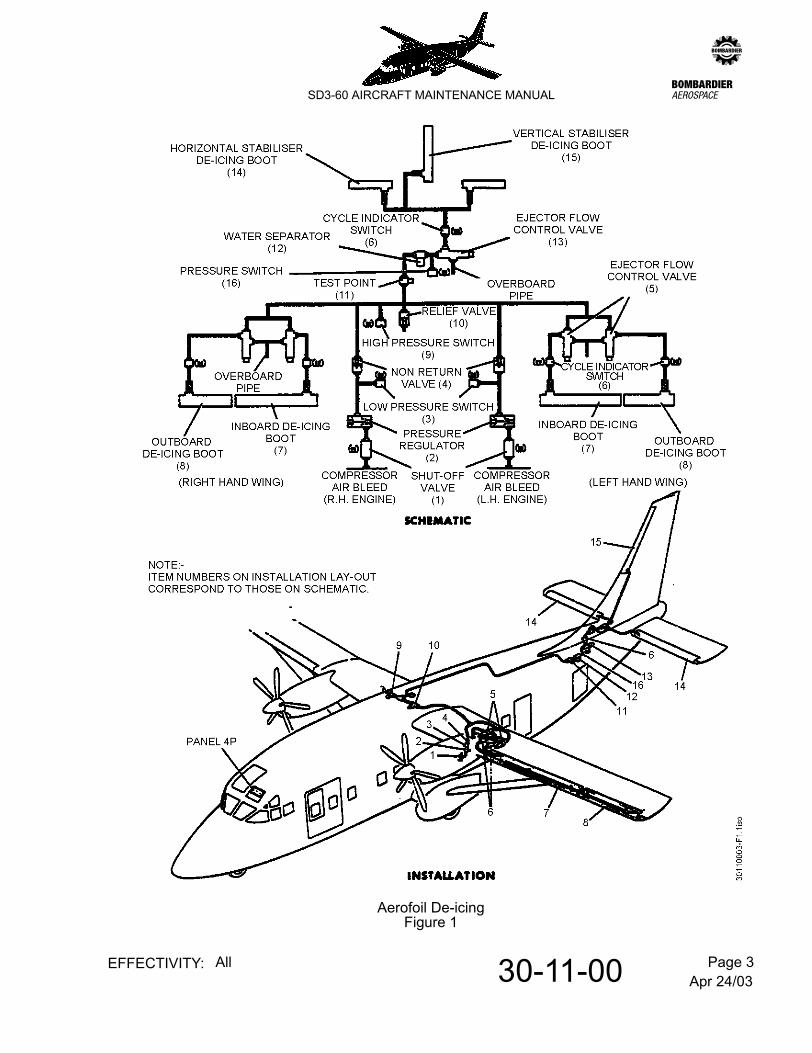
Refer to Figure 1.
The pneumatic power source to operate the system is derived from interstage P2.5 compressor bleed points on each engine.
The pneumatic de-icer consists of a smooth rubber fabric blanket containing small span wise de-icing tubes and is bonded to the aerofoil leading edge with cement.
Bleed air is directed through a shut-off valve, pressure regulator and a check valve to a common line and thence to each of five timer-controlled ejector flow control valves. When compressed air is emitted via the ejector valves, the boots become inflated and subsequent expansion produces cracks and shearing stresses in the ice, causing it to break its bond with the deicer surface and the scavenging effect of the airstream removes the ice particles. A relief valve at a mid point protects the de-icers from excess pressure.
When de-energised, the ejector valves act as jet pumps, creating a partial vacuum in their related boots such that they are sucked flat against the leading edge to present a smooth aerodynamic profile.
B. Ejector Flow Control Valves
The wing de-icer ejector valves are located at the intersection of the inner and outer wings and the empennage valve is in the fuselage roof. Each ejector valve is fitted with an electrically heated muff. A test point is provided to facilitate ground checks and/or pressure testing of the system.
C. Power supplies
Control and indication power supplies are taken from the 28V d.c. left and right shedding busbars via C/B Nos. 94 and 244 on respective distribution panels 1D and 2D.
D. System Controls
These are presented on panel 4P and comprise:-
(a) Two system and engine bleed control switches NORMal/SHUT
(b) The transistorized TIMER-OFF/1 MINute/3 MINute.
Apr 24/0330-11-00 Page 2EFFECTIVITY: All
zSD3-60 AIRCRAFT MAINTENANCE MANUAL
E. System Indication
(1) Shut-Off Valves
The 'open' - 'closed' indication of the Shut-Off Valves is signalled via an integral set of microswitches which operate in response to the solenoid valve movement.
Position indication is afforded by indicator modules on panel 4P (immediately above control switches).
(2) Cycling
Cycle indicator switches, sited downstream of each ejector valve connect a supply to the appropriate indicator light (green) on panel 4P when the related boot/s are on the inflation phase of a cycle.
(3) High/Low Pressure Warning (System)
(a) High Pressure Warning
A H.P. switch is sited upstream of the relief valve and will make a supply available (e.g. in the event of a failed pressure regulator) to the bleed air DUCT PRESSure light on panel 4P should the system pressure exceed 24 p.s.i; attention is drawn by the simultaneous illumination of the BLEED air module on the centralized warning panel.
(b) Low Pressure Warning
A L.P. switch is introduced immediately downstream of the pressure regulator in each engines delivery line. Should either switch 'make' (e.g. as a result of a burst pipe) a supply will be made available to the bleed air DUCT PRESSure light on panel 4P; attention is drawn by the simultaneous illumination of the BLEED air module on the centralized warning panel.
NOTE: Circuits for both warning systems are wired in series with engine oil pressure relays such that warning is only afforded when engines are running.
(4) Pressure Warning and Time Delay
A pressure switch is located between the ejector flow control valve and the water separator. The switch is set to illuminate an amber SYS Pressure caution light on panel 4P, on a falling de-icing boot inflation pressure of 11.5 psig. The A/ICE PANEL (BLEED on early aircraft) module on the centralized warning panel is also illuminated. The caution light will extinguish on a rising inflation pressure of 13.5 psig.
NOTE: The pressure switch only functions when the aircraft is in the air i.e. it is inhibited when the weight switches are operational.
Apr 24/0330-11-00 Page 3EFFECTIVITY: All
zSD3-60 AIRCRAFT MAINTENANCE MANUAL
Aerofoil De-icingFigure 1

Apr 24/0330-11-00 Page 4EFFECTIVITY: All
zSD3-60 AIRCRAFT MAINTENANCE MANUAL
A time delay relay routes the pressure switch output to the SYS P indication, and is set to approximately 60 seconds to avoid any nuisance warnings during the landing flare, where lower boot inflation pressures would be expected.
(5) Spar Box Overheat Warning
This facility is shared with the air conditioning system. Refer to 21-00-00, pb1.
2. Operation
A. General
The system operates in the dormant or de-icing role as respectively described in B and C.
B. Dormant Function
With engines running and the controls on panel 4P set thus:-
the five ejector valves will constantly operate in the jet pump mode to keep the boots sucked flat to their respective leading edges.
C. De-icing Function
With engines running and the controls on panel 4P set thus:-
the boots will commence and repeat flexing (inflation/deflation) in the sequence inner wings - outer wings - tail.
During inflation, for either one minute or three minute cycles, the inner wing ejector valves are energised for 5 seconds and then simultaneously de-energised with the energising of the outer wing ejector for 5 seconds, followed by the energising of the tail ejector valve for 5 seconds.
This is followed by a dwell period of 45 seconds or 165 seconds (depending on the cycle duration).
The cycle is repeated as long as the timer is switched ON. If the timer is switched OFF at any time the timer will complete the cycle and return to the starting position. Momentary operation of the control switch provides one operational cycle of the de-icer boots.
During the period of de-energisation of each ejector valve, air is removed from the related boot/s by the valve's jet pump action.
WINGS & TAIL BLEED air control switches : NORMalTIMER : OFF
WINGS & TAIL BLEED air control switches : NORMalTIMER : 1 MINute/3 MINute
Jun 30/0130-11-00 Page 201EFFECTIVITY: All
zSD3-60 AIRCRAFT MAINTENANCE MANUAL
AMM30-11-00 4.0.0.0AEROFOIL DE-ICING - MAINTENANCE PRACTICES
1. Adjustment/Test
A. Function the system
(1) Start engines
(2) Check that C/B Nos. 94 and 244 on respective distribution panels 1D and 2D are closed.
(3) On panel 4P perform the following:-
(a) Check that WINGS & TAIL BLEED air control switches are set to NORMal.
(b) Set TIMER switch to 1 MINute cycle.
(4) With reference to appropriate indicator lights, check that the ejector flow control valves are energised in the following order and for the period specified.
(a) INNER wing (left and right) - 5 seconds
(b) OUTER wing (left and right) - 5 seconds
(c) TAIL boots - 5 seconds, followed by a 45 second dwell period to complete the cycle, which will then repeat itself until the TIMER is switched OFF.
(5) Set TIMER switch to 3 MINute cycle and repeat operation (4), checking that there is a 165 second dwell period to complete the cycle.
(6) Switch TIMER - OFF.
(7) Select left WINGS & TAIL BLEED air control switch to SHUT and TIMER switch to 1 MINute cycle, and repeat operation (4).
(8) Return left control switch to NORMal and select right control switch to SHUT repeating operation (4).
(9) Return right control switch to NORMal and switch timer - OFF.
(10) Check that all cycling indication lights are extinguished.
(11) Shut down engines.
Jun 30/0130-11-01 Page 201EFFECTIVITY: All
zSD3-60 AIRCRAFT MAINTENANCE MANUAL
AMM30-11-01 5.0.0.0CHECK VALVES (ENGINE AIR BLEED LINES) - MAINTENANCE PRACTICES
1. Adjustment/Test
NOTE: For convenience of maintenance, the testing of the high pressure switch and relief valve are carried out in the same procedure.
A. Function check the valves
Special tools and equipment:
Regulated air pressure supply (0-100 p.s.i.)
(1) Close C/B Nos. 94 and 244 on respective distribution panels 1D and 2D. Select the TIMER switch OFF.
CAUTION: PLACARD THE TIMER SWITCH TO ENSURE THAT IT IS NOT SELECTED ON DURING HIGH PRESSURE TESTS.
(2) Refer 6-30-00, pb1. Remove the following panels:-
(3) Disconnect de-icing pipes from bleed points on engines and blank off engine connections.
(4) Connect regulated air pressure supply to test point and raise pressure slowly to 20 p.s.i. maintaining flow to compensate for loss through ejector valves.
(5) Check that little or no leakage emits from the disconnected piping at the engines, indicating that the check valves are functional.
NOTE: The label at the test point, restricting pressure to 20 p.s.i. is to be ignored when performing the following test - the restriction only applies if boots are cycle functioned from an external supply (engines stopped).
(6) Increase the pneumatic pressure slowly through 20 p.s.i. checking that:-
(a) the relief valve (accessed via panel 314 MZ) discharges air on a rising pressure of 20 ± 1 p.s.i.
420 AT510 AT312 TZ (rear baggage compartment aft bulkhead)
Jun 30/0130-11-01 Page 202EFFECTIVITY: All
zSD3-60 AIRCRAFT MAINTENANCE MANUAL
(b) a continuing increase in pressure (to compensate for relief valve loss) will cause the high pressure switch to illuminate the DUCT PRESSure light on panel 4P. before reaching 24 p.s.i.
NOTE: Check that on a falling pressure of 22 p.s.i. the high pressure switch 'breaks', extinguishing the DUCT PRESSure light.
(7) Reduce pressure to 20 p.s.i. and check that relief valve has reset.
(8) Reduce pressure to zero and disconnect air pressure supply.
(9) Remove blanks from P2.5 engine connections and re-connect associated piping.
(10) Close access panels.
(11) Remove placards and close C/B Nos. 94 and 244.
Jun 30/0130-11-06 Page 201EFFECTIVITY: All
zSD3-60 AIRCRAFT MAINTENANCE MANUAL
AMM30-11-06 6.0.0.0RELIEF VALVE - MAINTENANCE PRACTICES
1. Adjustment/Test
A. Function check the relief valve.
For convenience of maintenance, the relief valve is functioned during check valves (engine air bleed lines) test. Refer to 30-11-01, pb201.
Jun 30/0130-11-11 Page 201EFFECTIVITY: All
zSD3-60 AIRCRAFT MAINTENANCE MANUAL
AMM30-11-11 7.0.0.0LOW PRESSURE SWITCHES - MAINTENANCE PRACTICES
1. Adjustment/Test
A. Function check the pressure switches
Special tools and equipment:
Regulated air pressure supply.
(1) Refer to 12-09-03, pb301. Provide electrical power.
(2) Check that C/B Nos 94 and 244 on respective distribution panels 1D and 2D are closed.
(3) Obtain access to both engines by removing panel 410AL.
(4) Disconnect de-icing pipes from interstage P2.5 bleed point on engines and blank off engine connections.
(5) Gain access at panels 510TT or 510BB (left) and 610TT or 610BB (right) and disconnect piping from outlet side of the check valves. Blank off piping and valves.
(6) Check left pressure switch as follows:-
(a) Select left BLEED air switch to NORMal.
(b) Open C/B No. 16 on distribution panel 1D (de-energising the left engine oil pressure relay thus permitting the bleed air - DUCT PRESSure light on panel 4P to illuminate under the influence of the left duct pressure switch, with engine stopped).
(c) Connect regulated air pressure supply to the previously disconnected piping at the engine P2.5 bleed point.
(d) Raise pressure slowly, checking that the warning light is extinguished when the pressure reaches 6 p.s.i. Reduce pressure slowly and check that the light illuminates at 5 ± 0.25 p.s.i.
(e) Reduce pressure to zero and disconnect air pressure supply.
(f) Close C/B No. 16.
(g) Select left BLEED air switch to SHUT.
(7) Check right pressure switch as follows:-
(a) Select right BLEED air switch to NORMal.
Jun 30/0130-11-11 Page 202EFFECTIVITY: All
zSD3-60 AIRCRAFT MAINTENANCE MANUAL
(b) Open C/B No. 116 on distribution panel 2D (de-energising the right engine oil pressure relay, thus permitting the bleed air - DUCT PRESSure light on panel 4P to illuminate under the influence of the right duct pressure switch, with engine stopped).
(c) Connect regulated air pressure supply to the previously disconnected piping at the right engine P2.5 bleed point.
(d) Raise pressure slowly, checking that the warning light is extinguished when the pressure reaches 6 p.s.i. Reduce pressure to slowly and check that the light illuminates at 5 ± 0.25 p.s.i.
(e) Reduce pressure to zero and disconnect air pressure supply.
(f) Close C/B No. 166.
(g) Select right BLEED air switch to SHUT.
(8) Remove blanks and re-connect associated piping at check valves and engine P2.5 bleed points (left and right). Replace access panels.

Jun 30/0130-11-16 Page 201EFFECTIVITY: All
zSD3-60 AIRCRAFT MAINTENANCE MANUAL
AMM30-11-16 8.0.0.0HIGH PRESSURE SWITCH - MAINTENANCE PRACTICES
1. Adjustment/Test
A. Function check the pressure switch.
For convenience of maintenance, the high pressure switch is functioned during check valves (engine air bleed lines) test. Refer to 30-11-01, pb201.
Jun 30/0130-11-21 Page 201EFFECTIVITY: All
zSD3-60 AIRCRAFT MAINTENANCE MANUAL
AMM30-11-21 9.0.0.0TRANSISTORISED TIMER - MAINTENANCE PRACTICES
1. Adjustment/Test
A. Function check the timer
The timer will be proved functional by the satisfactory completion of the system function test. Refer to 30-11-00, pb201.
Jun 30/0130-11-26 Page 201EFFECTIVITY: All
zSD3-60 AIRCRAFT MAINTENANCE MANUAL
AMM30-11-26 10.0.0.0EJECTOR FLOW CONTROL VALVES - MAINTENANCE PRACTICES
1. Adjustment/Test
A. Function check the valves
The valves will be proved functional by the satisfactory completion of the system function test. Refer to 30-11-00, pb201.
Jun 30/0130-11-31 Page 201EFFECTIVITY: All
zSD3-60 AIRCRAFT MAINTENANCE MANUAL
AMM30-11-31 11.0.0.0CYCLE INDICATOR SWITCHES (BOOT FUNCTION) - MAINTENANCE PRACTICES
1. Adjustment/Test
A. Function check the switches.
The switches will be proved functional by the satisfactory completion of the system function test. Refer to 30-11-00, pb201.
Jun 30/0130-11-36 Page 201EFFECTIVITY: All
zSD3-60 AIRCRAFT MAINTENANCE MANUAL
AMM30-11-36 12.0.0.0BOOT DE-ICERS - MAINTENANCE PRACTICES
1. Servicing
A. General
An average life of approximately 5 years can be expected if the following precautions are observed:-
(1) Inspect the de-icers regularly and repair all damage promptly.
(2) Work stands should be suitably padded on those areas which could come in contact with installed de-icers and ladders should not be laid against aerofoil leading edges having de-icers installed.
(3) When refuelling an aircraft, do not drag the service hose over the boots. The de-icing boots should be protected with suitable padding.
(4) Tools and other sharp instruments should not be laid on the de-icing boots during servicing procedures.
B. Cleaning
(1) Ensure that de-icers are kept free from oil, gasoline, paint remover, solvents and other injurious substances. Cleaning should be performed using mild soap and water solution.
CAUTION: SOLUTION TEMPERATURE MUST NOT EXCEED:-
(A) 140°F FOR STABILIZER INSTALLED DE-ICERS (ESTANE)
(B) 180°F FOR WING DE-ICERS (NEOPRENE)
(2) If performing general external cleaning operations on the aircraft employing cleaning compound MIL-C-22543; take account of the following:-
CAUTION: (A) MIL-C-22543 CLEANING COMPOUND CAN DAMAGE THE SURFACE PLY OF STABILIZER SITED DE-ICERS (ESTANE). STEPS MUST BE TAKEN TO COVER AND EFFECTIVELY PROTECT THE SURFACE OF SUCH DE-ICERS BEFORE WASHING THE AIRCRAFT WITH THESE CLEANING COMPOUNDS.
(B) WING SITED DE-ICERS (NEOPRENE) SHOULD HAVE A FINAL WASH WITH CLEAN WATER.
C. Protective treatment
(1) Age Master No. 1 application (Neoprene De-icers only), these are fitted to the wings.
(a) The work area should be adequately ventilated during the application process.
Jun 30/0130-11-36 Page 202EFFECTIVITY: All
zSD3-60 AIRCRAFT MAINTENANCE MANUAL
(b) Age Master may be applied by brushing, swabbing or rolling. Plastic or rubber gloves should be used with the swab method to prevent staining of the skin. Spraying is not recommended to avoid loss of vital components needed for a protective agent to penetrate rubber. Application by spraying is also a fire hazard.
(c) A minimum of two coats are required for the complete process.
(d) Waterless hand cleanser should be used to clean hands and equipment and also remove stains.
(e) One gallon will treat 150 - 170 square feet (14 - 18 square meters) two coats.
1 Clean the de-icer surfaces as detailed in para B. and mask the surrounding areas to prevent staining.
2 Apply the first coat at a rate of 0.4 - 0.5 fluid ounces per square foot ensuring that the surfaces are completely covered. Allow 5 to 10 minutes to dry.
NOTE: Swab applicators should be approximately 2 in. by 4 in. formed from lint-free cloth. The swab should be wet through but not dripping and strokes consistent.
3 Apply the second coat as detailed in para 2 and allow 20 to 30 minutes to dry. When using Agemaster No. 1 on Neoprene de-icers, allow for it to soak into the de-icers, before you fly the aircraft.
NOTE: The total coverage should be approximately 0.75 fluid ounces per square foot (240 ml per square meter) for effective protection.
Jun 30/0130-11-36 Page 203EFFECTIVITY: All
zSD3-60 AIRCRAFT MAINTENANCE MANUAL
D. Adhesion reduction
(1) ICEX application
WARNING: FAILURE TO FOLLOW DIRECTIONS COULD RESULT IN BODILY INJURY OR DEATH. HARMFUL VAPOURS MAY CAUSE SKIN AND EYE IRRITATION. USE ONLY IN A WELL VENTILATED AREA. TO AVOID PROLONGED OR REPEATED SKIN CONTACT, USE RUBBER OR NEOPRENE GLOVES (INDUSTRIAL/ALKALINE RESISTANT TYPE). WEAR CHEMICAL GOGGLES. WHEN CONTAINER IS NOT IN USE, KEEP IT TIGHTLY CLOSED TO AVOID EVAPORATION. KEEP AWAY FROM OPEN FLAMES AND ELECTRIC HEATERS. DO NOT DISPOSE OF EMPTY CONTAINER BY BURNING. BURNING GIVES OFF TOXIC SUBSTANCES. IF THERE IS EYE CONTACT, FLUSH WITH WATER FOR 15 MINUTES. USE SOAP AND WATER AFTER SKIN CONTACT. IF EYE OR SKIN IRRITATION PERSISTS, SEE A PHYSICIAN. IF SWALLOWED, DO NOT INDUCE VOMITING. SEE A PHYSICIAN IMMEDIATELY. KEEP OUT OF REACH OF CHILDREN.
B.F. Goodrich ICEX is a silicone based material specifically compounded to reduce the strength of adhesion between ice and the rubber surfaces of the aircraft de-icers. ICEX will not harm rubber and offers added ozone protection.
Properly applied and renewed at periodic intervals, ICEX provides a smooth polished film that evens out the microscopic irregularities on the surface of the rubber parts. ICEX provides a barrier to ice adhesion and causes ice to shear easily when the de-icers are operated.
One quart will provide 500 square feet coverage when applied as directed.
ICEX may be applied directly over AGE-MASTER No. 1 treated surface, so long as the AGE-MASTER No. 1 has dried for 24 hours and is clean. Otherwise:
(a) Thoroughly wash using soap and water solution.
(b) Remove substances which cannot be removed by soap and water using isopropyl alcohol; however if this is done the surface must be cleaned again with soap and water.
(c) Rinse thoroughly with clean water and allow to dry.
ICEX should be applied sparingly to achieve the optimum results. If the application is too heavy, it will cause the surface to become sticky, thus attracting runway dust and reducing ice removing efficency.
The frequency of application will be dependent upon the number of flight hours accumulated and the type of weather encountered. One application of ICEX may be expected to last for 50 flight hours during the icing season. Re-apply as often as required to maintain a thin polished film on the de-icer surfaces.
Jun 30/0130-11-36 Page 204EFFECTIVITY: All
zSD3-60 AIRCRAFT MAINTENANCE MANUAL
ICEX may be applied immediately before flight. However, DO NOT apply ICEX over Agemaster No. 1 that has not cured for at least 24 hours.
2. Removal/Installation
WARNING: CEMENT AND SOLVENT VAPOURS ARE TOXIC AND EXTREMELY FLAMMABLE. USE ONLY IN A WELL VENTILATED AREA AWAY FROM SPARKS OR FLAMES. AVOID PROLONGED BREATHING OF VAPOURS - EXCESSIVE EXPOSURE COULD CAUSE INJURY OF DEATH. IF DIZZINESS OR NAUSEA OCCUR, OBTAIN FRESH AIR IMMEDIATELY. AVOID CONTACT WITH SKIN OR EYES. USE SOLVENT - RESISTANT GLOVES TO MINIMIZE SKIN EXPOSURE. USE SAFETY GLASSES TO MINIMIZE CHANCE OF EYE CONTACT. IF EYE CONTACT OCCURS, FLUSH EYES WITH WATER FOR 15 MINUTES AND SEE A PHYSICIAN. IF SKIN CONTACT OCCURS, WASH THOROUGHLY WITH SOAP AND WATER. IF SWALLOWED, DO NOT INDUCE VOMITING. SEE A PHYSICIAN IMMEDIATELY.
REFER TO 12-09-01, PB201. ENSURE AIRCRAFT IS ELECTRICALLY GROUNDED TO PREVENT STATIC SPARKS WHICH COULD IGNITE SOLVENT VAPOURS.
A. Remove wing De-icers (neoprene) or stabilizer De-icers (estane).
NOTE: Boots to be removed using the minimum amount of Toluol possible.
(1) Apply Toluol to the seam line of one corner of the upper trailing edge of the De-Icer and apply force to peel back the boot.
(2) Using the solvent, separate the De-Icer from the aerofoil for a distance of four inches all the way along the upper trailing edge.
(3) Continue to use solvent to soften the adhesion line and pull the boot down towards lower trailing edge with uniform force.
(4) Disconnect flexible hose from De-Icer connection.
(5) Remove installation cement using BF Goodrich KE9002 paint remover, Toluol or equivalent.
B. Preparation of Leading Edges
(1) Using 1" masking tape, mask off area to be covered by De-icer; allow 1/2" extra on each side for non-recessed De-icers. If adhesion test is to be made, allow 1" on end to install adhesion test strip.
WARNING: CONFIRM THAT THE AIRCRAFT IS ELECTRICALLY GROUNDED TO PREVENT STATIC SPARKS WHICH COULD IGNITE SOLVENT VAPOURS.
(2) Thoroughly clean the metal surfaces with cleaning solvent at least twice. Remove all paint and primer within the masked area. For final cleaning, swab with clean solvent and quickly wipe dry with a clean, dry cloth to avoid leaving a film.
Jun 30/0130-11-36 Page 205EFFECTIVITY: All
zSD3-60 AIRCRAFT MAINTENANCE MANUAL
(3) It is permissible to install De-icers on alodined or anodized surfaces.
NOTE: If zinc chromate primer is unaffected by scrubbing with the cleaning solvent, it does not have to be completely removed to facilitate De-icer installation as long as adequate adhesion is obtained (see para 3.A). If adhesion is not adequate, soak primer with BF Goodrich No. KE-9002 or equivalent, then scrub with Toluol to remove primer.
(4) Fill gaps of skin splices that lead under the De-icers with sealing compound EC-801.
C. Preparing De-icer
NOTE: If adhesion test is to be made, prepare and mount the De-icer adhesion test strip(s) in exactly the same manner and at the same time that the De-icer is prepared and mounted (see para 3.A).
(1) Moisten a lint free cloth (i.e. cheesecloth) with cleaning solvent and carefully clean the rough, back surface of the De-icer at least twice. Change cloths frequently to avoid recontamination of the cleaned surfaces.
CAUTION: ESTANE DE-ICERS CAN BE DAMAGED BY MEK OR ACETONE USE TOLUOL WHEN CLEANING AND INSTALLING THESE DE-ICERS.
DO NOT SATURATE THE BACK SURFACE TOO HEAVILY WITH SOLVENT OR SCRUB REPEATEDLY. ALLOW TO DRY THOROUGHLY BEFORE CEMENTING.
D. Cementing De-icer and Leading Edge
WARNING: 1300L CEMENT CONTAINS MEK AND IS EXTREMELY FLAMMABLE. EXTINGUISH ALL OPEN FLAMES. AVOID SPARKS. USE ONLY IN WELL VENTILATED AREAS. AVOID PROLONGED BREATHING OF VAPOURS. AVOID SKIN CONTACT.
(1) Thoroughly mix the 1300L installation cement; if necessary, the cement may be thinned with Toluol or MEK (up to 5% by volume). Apply one even brush coat to the cleaned back surface of the De-icer and to the cleaned installation surface.
NOTE: For best results, apply cement at an ambient temperature of 65° - 75° F (18° - 24°C), do not apply cement below 50°F (10°C) or above 110°F (43°C).
Allow the cement to dry a minimum of one hour at 50°F (10°C) or above when the relative humidity is less than 75%. If the humidity is 75-90% allow additional drying time. DO NOT apply the cement if the relative humidity is higher than 90%, OR if the temperature is below 50°F (10°C). For best results apply cement at an ambient temperature of 65-75°F (18-24°C).
(2) Re-stir cement and apply a second coat to both surfaces and allow to air dry a minimum of one hour. De-icer and leading edge may be cemented for a maximum of 48 hours before actual installation if cemented parts are covered and kept clean.
Jun 30/0130-11-36 Page 206EFFECTIVITY: All
zSD3-60 AIRCRAFT MAINTENANCE MANUAL
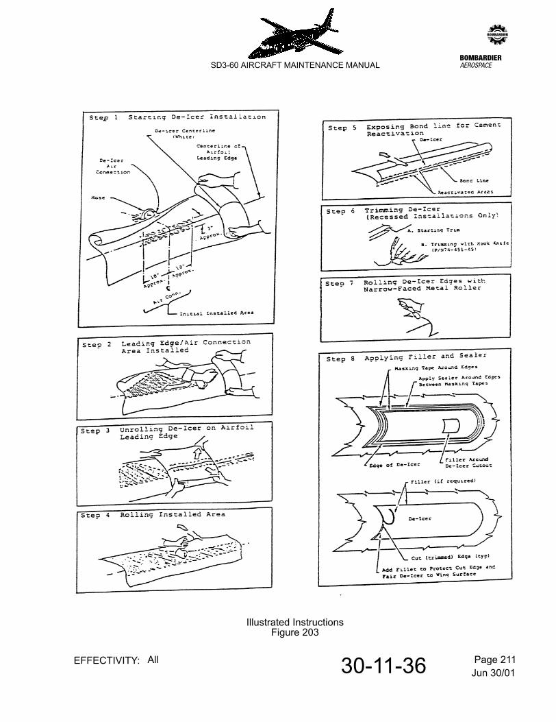
E. Mounting De-icer
Refer to Figure 203.
NOTE: It is recommended that associated hoses are newly replaced before installing de-icer boots.
(1) Pull the end of the hose through the connection hole in the aerofoil. Where there is more than one hose, be sure each hose end is brought out through its proper hole to avoid improper inflation sequence.
(2) Roll De-icer up to about 18" on each side of the air connection. Roll with cemented side out so that the De-icer centreline rolls on itself. Position the De-icer so its centreline is against the centreline leading edge of the aerofoil and so the air connection will match the hole in the aerofoil.
(3) Securely attach hose to De-icer air connection with Tinnerman/Adel clamps or other suitable clamps. Tighten each clamp but not so tight that the hose is damaged.
(4) Installing De-icer along its centreline.
NOTE: Installation may be best accomplished using two people; one to hold and guide the De-icer during installation, the other to reactivate the cement and roll the De-icer down.
Using a clean lint-free cloth dampened with Toluol, reactivate (tackify) a 3" wide x 18" long section of cement on the airfoil leading edge centred at the air connection. If the air connection is on or near the leading edge, reactivate the cement for about 3" around the leading edge/air connection hole so that it may be installed first. Reactivate a matching section on the de-icer's cemented surface. If air connection is above or below leading edge, de-icer will adhere only where cement is reactivated.
When the cement is tacky, press the De-icer to the aerofoil making sure that the centrelines coincide and that the air connection will mate with the hole in the aerofoil skin. Then, rubber roll the De-icer firmly against the aerofoil skin in the tackified area Reactivate the cement on the aerofoil leading edge and the De-icer (approximately 3" wide) for an addional 2 - 3 feet along centreline. When the cement is tacky, unroll the De-icer against the aerofoil leading edge. Lightly tension the De-icer to avoid wrinkles. Continue this method until the entire length of the De-icer is installed along its centreline, then roll the installed area down firmly with a rubber roller.
(5) If the De-icer should attach 'off course' (centreline not coinciding with leading edge centreline), apply Toluol with small brush or squirt can to soften the bond line. Apply only a minimum of solvent to the bond line while applying sufficient tension to peel back the De-icer. Remove slowly enough to allow the solvent to soften the cement, thus preventing removal of cement coat or injury to the De-icer. Avoid using excess quantitites of solvent. To avoid De-icer damage, avoid twisting, bending De-icer sharply, or jerking
Jun 30/0130-11-36 Page 207EFFECTIVITY: All
zSD3-60 AIRCRAFT MAINTENANCE MANUAL
De-icer loose from bonded area. Allow to dry thoroughly before continuing with application. Re-apply cement if any has pulled loose.
(6) Installing Remainder of De-icer
After the De-icer is fastened in place along its centreline, begin to reactivate the cement on either the upper or lower surface. Start at inboard end and wipe with Toluol moistened cloth first along the cemented aircraft's surface in one direction and return to start by wiping the corresponding cemented surface of the De-icer (approximately 3" wide x 60" long area). Too much wiping will remove cement. Hold De-icer back to reveal bond line and begin reactivating.
Keep moistened cloth tight into the fold of the bond line of the De-icer to the aircraft's skin. To avoid trapping air, do not allow the De-icer to touch the reactivated cement until the desired time. Roll down De-icer with rubber roller starting at the bond line and roll spanwise while working toward the trailing edge. Work carefully to avoid trapping air. Let the roller do the work of mating the two surfaces.
(7) Rub roller spanwise over entire surface of De-icer applying pressure to ensure a good bond. Roll trailing edges outside the inflatable area with a narrow stitcher roller.
F. Sealing of Boots
(1) Neoprene Boots
(a) Remove all masking tapes.
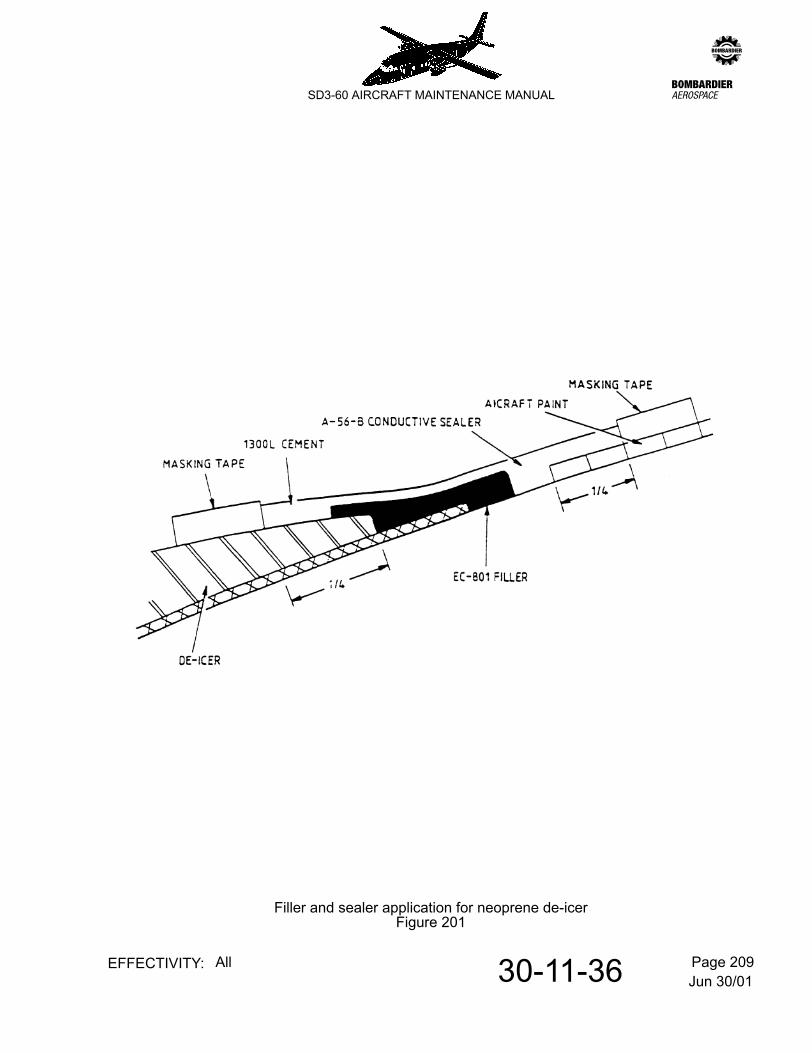
(b) Apply masking tape to De-icer edges and trimmed ends or at gaps between sections. Filler EC801 should be applied to protect the edges of a De-icer and to fair it to the adjacent surface. Refer to Figure 201. Remove tape.
(c) Apply masking tape to de-icer surface approximately 1/4" in from trailing edges for EC801 filling. On unpainted surfaces apply second tape approximately 1/4" from trailing edge forming a neat, straight line. On painted surfaces, apply second masking tape approximately 1/4" back from paint edge.
(d) Apply 2 brush coats of A-56-B conductive cement to surfaces between tapes and to EC801 seams being sure that the conductive coating (A-56-B) is continuous from the de-icer surface to the wing painted surface. A drying time of 10-15 minutes between coats should be allowed.
(2) Estane Boots (Ref Kit No. 74-451-P)
NOTE: All work should be done inside a hangar where the air temperature is between 60°F and 90°F. The cements will not cure properly at lower temperatures.
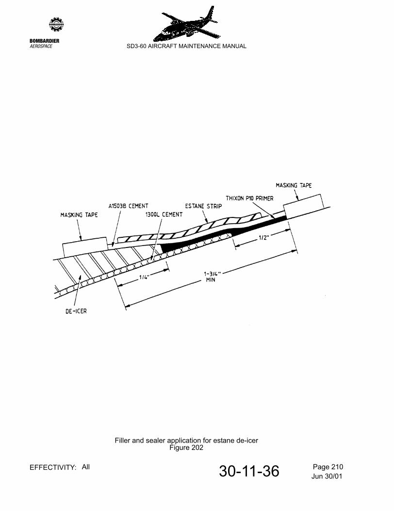
(a) Mask off area 1/2" outboard of the 1300L cement (de-icer installation cement), but do not exceed 1-1/2" outboard of de-icer edge. Apply masking tape 1/4" inboard on de-icer. Refer to Figure 202.
Jun 30/0130-11-36 Page 208EFFECTIVITY: All
zSD3-60 AIRCRAFT MAINTENANCE MANUAL
(b) Brush coat one coat of Thixon P-10 primer over bare clean metal and 1300L cement up to the edge of de-icer (do not apply primer over de-icer). Let Thixon P-10 dry a minimum of 30 minutes.
(c) Pre-mix A1503B cement and A1343B accelerator in a ratio of 16:1 by volume. Brush coat one coat of pre-mixed A1503B cement over Thixon P-10 covered area and 1/4" up on the de-icer edge.
(d) Using 1-1/2" wide Estane strip, apply strip around perimeter of de-icer over cemented area.
NOTE: The Estane edge strip must overlap the de-icer edge and span over the exposed 1300L cement to be effective. Failure to cover the 1300L cement can result in debonding.
To apply strip, tackify by wiping the side opposite the backing with a soft, lint free cloth dampened by Toluol. Tackify short areas (15-20 inches) of the strip at a time and stitch down with a roller. Remove backing while applying strip, prior to stitching.
(e) Remove masking tape immediately after applying sealer. (Before cement dries).
(f) Allow at least 4 hours for cement to dry before flying the aircraft.
3. Adjustment/Test
A. Adhesion test (Optional)
(1) Using excess material trimmed from ends of any wing or empennage De-icers, prepare one test specimen for each De-icer installed. This specimen should be one inch wide and four or more inches long. Cement it to the installation surface adjacent to installed De-icer following the identical procedure used for installation. Leave one inch of the strip uncemented to attach a clamp. Four hours or more after the De-icer installation, attach a spring scale to the uncemented end of each strip and measure the force required to remove the strip at a rate of one inch per minute; the pull shall be applied 180° to the surface (Strip doubled back on itself).
(2) A minimum of five pounds tension (pull) should be required to remove the test strip. If less than five pounds is found, then acceptability of the De-icer adhesion shall be based on the following test:
(a) Carefully lift one corner of the De-icer in question sufficiently to attach a spring clamp.
(b) Attach a spring scale to this clamp and pull with force 180° to the surface and in such a direction that the De-icer tends to be removed on the diagonal.
Jun 30/0130-11-36 Page 209EFFECTIVITY: All
zSD3-60 AIRCRAFT MAINTENANCE MANUAL
Filler and sealer application for neoprene de-icerFigure 201
Jun 30/0130-11-36 Page 210EFFECTIVITY: All
zSD3-60 AIRCRAFT MAINTENANCE MANUAL
Filler and sealer application for estane de-icerFigure 202
Jun 30/0130-11-36 Page 211EFFECTIVITY: All
zSD3-60 AIRCRAFT MAINTENANCE MANUAL
Illustrated InstructionsFigure 203
Jun 30/0130-11-36 Page 212EFFECTIVITY: All
zSD3-60 AIRCRAFT MAINTENANCE MANUAL
(c) If a force of five pounds per inch of width can be exerted under these conditions, the installation shall be considered to be satisfactory. Remember, the width increases as the corner peels back.
(d) Re-cement the corner following the installation procedure.
CAUTION: FAILURE TO ACHIEVE FIVE POUNDS ADHESION PER INCH OF WIDTH REQUIRES RE-INSTALLATION OF THE DE-ICER.
(3) Possible reasons for failure are: Dirty surfaces; cement not reactivated properly; cement not mixed thoroughly. Corrosion of the metal skin may occur if good adhesion is not attained, especially around rivet heads and metal skin splices.
(4) If these adhesion requirements are met, the aircraft may be flow immediately.
CAUTION: DO NOT INFLATE DE-ICERS WITHIN 48 HOURS OF INSTALLATION.
B. Leak test
Special tools and equipment:
Regulated dry air or nitrogen supply (0 - 100 psi).
Adapter Pt No. NIV 379.
Solution of soapy water
Marker chalk
(1) Cap off or plug wing de-icer boot vent holes located under wing, outboard of engine tail cone.
(2) Connect regulated pneumatic supply to test point (situated between stns 595-620 right side of empennage) using adapter Pt No. NIV 379.
(3) Increase the pneumatic pressure slowly to 20 psi. (Relief valve will operate at 21 ± 1 psi.)
(4) Remove plastic cap from plunger on stabiliser ejector flow control valve (situated to the rear of Stn 620 right side of empennage).
(5) Depress plunger and hold. This will allow stabiliser boots to inflate continuously, (to be depressed whilst de-icer boots are leak checked).
(6) Apply soapy water to each stabiliser boot in turn.
(7) Identify areas of leaks with marker chalk.
(8) Release plunger and refit plastic cap.
(9) Repeat procedures (6) and (7) for each wing de-icer boot.

Jun 30/0130-11-36 Page 213EFFECTIVITY: All
zSD3-60 AIRCRAFT MAINTENANCE MANUAL
(10) Shut off pneumatic supply, leaving connected to the system.
(11) Ensure all water, if present, is removed from the affected de-icer boot, this will entail slitting the boot section containing water not greater than 1/2 inch.
NOTE: If more than one section is found to contain water, stagger the slits. (Reference patch limitations, para 4.C.).
(12) Carry out patch repairs as necessary in accordance with para 4.C.
(13) Repeat leak test, procedures (3) thru (8) for each de-icer boot as necessary.
(14) Disconnect pneumatic supply.
(15) Remove wing de-icer boot vent holes caps or plugs.
C. Function Test
Refer to 30-11-00, pb201.
4. Approved Repairs
A. General
The undernoted repair kits are supplied with complete instructions for use:
B. Patch Repair Procedures
NOTE: For patch limitations - refer to para C.
(1) For Neoprene De-Icers:
(a) Clean damaged area with a clean lint free cloth moistened with uncontaminated Toluol. Change cloths often to avoid recontamination of the damaged area.
(2) For Estane De-Icers:
(a) Wash surface thoroughly with soap or detergent and warm water. Repeat until surface is visibly free from all oil and dirt. A soft scrub brush may be used if desired.
(3) Select a patch to extend over at least a half inch in all directions, beyond the damaged area.
(4) Buff area around damage with buffing stick so that conductive coating is removed and exposed surface is roughened.
74-451-C - Neoprene (Wing de-icing mats)74-451-H - Estane (Empennage de-icing mats)
Jun 30/0130-11-36 Page 214EFFECTIVITY: All
zSD3-60 AIRCRAFT MAINTENANCE MANUAL
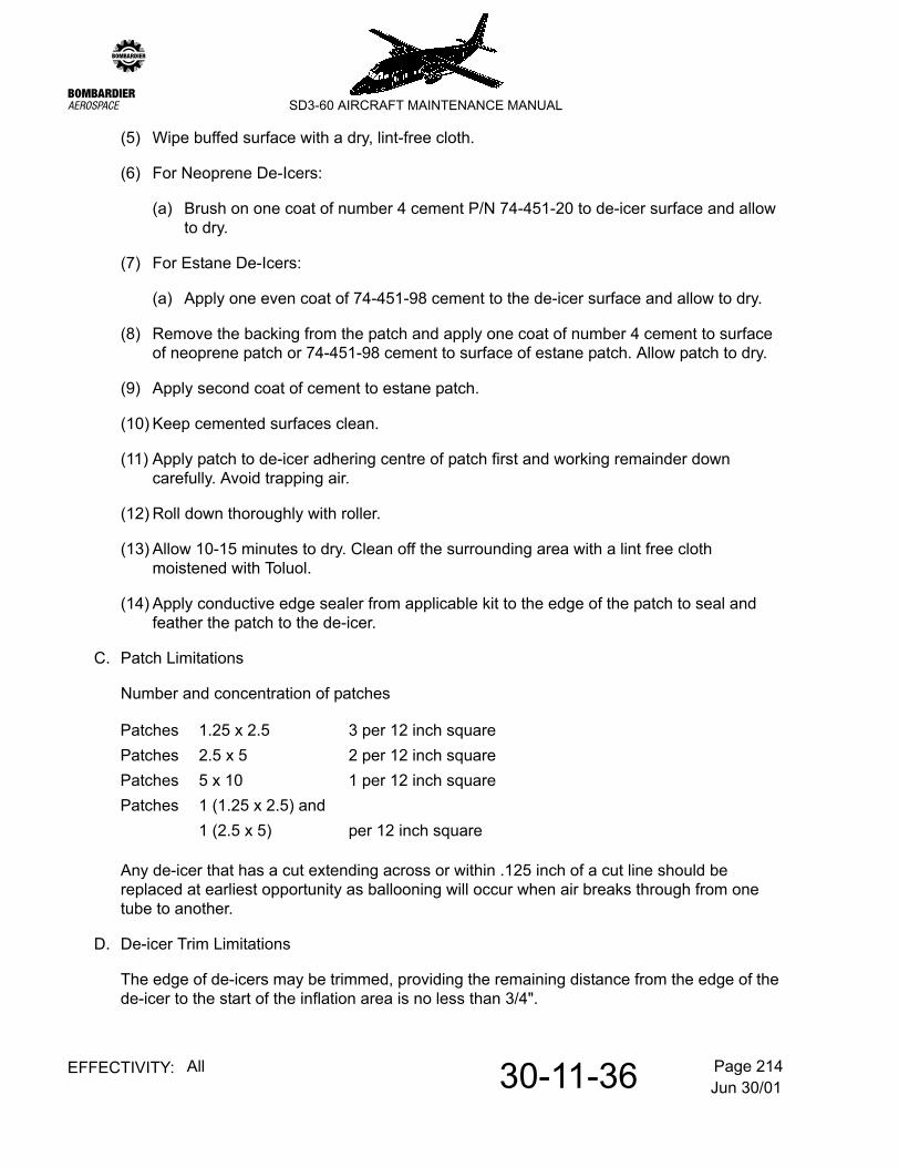
(5) Wipe buffed surface with a dry, lint-free cloth.
(6) For Neoprene De-Icers:
(a) Brush on one coat of number 4 cement P/N 74-451-20 to de-icer surface and allow to dry.
(7) For Estane De-Icers:
(a) Apply one even coat of 74-451-98 cement to the de-icer surface and allow to dry.
(8) Remove the backing from the patch and apply one coat of number 4 cement to surface of neoprene patch or 74-451-98 cement to surface of estane patch. Allow patch to dry.
(9) Apply second coat of cement to estane patch.
(10) Keep cemented surfaces clean.
(11) Apply patch to de-icer adhering centre of patch first and working remainder down carefully. Avoid trapping air.
(12) Roll down thoroughly with roller.
(13) Allow 10-15 minutes to dry. Clean off the surrounding area with a lint free cloth moistened with Toluol.
(14) Apply conductive edge sealer from applicable kit to the edge of the patch to seal and feather the patch to the de-icer.
C. Patch Limitations
Number and concentration of patches
Any de-icer that has a cut extending across or within .125 inch of a cut line should be replaced at earliest opportunity as ballooning will occur when air breaks through from one tube to another.
D. De-icer Trim Limitations
The edge of de-icers may be trimmed, providing the remaining distance from the edge of the de-icer to the start of the inflation area is no less than 3/4".
Patches 1.25 x 2.5 3 per 12 inch squarePatches 2.5 x 5 2 per 12 inch squarePatches 5 x 10 1 per 12 inch squarePatches 1 (1.25 x 2.5) and
1 (2.5 x 5) per 12 inch square
Jun 30/0130-11-36 Page 215EFFECTIVITY: All
zSD3-60 AIRCRAFT MAINTENANCE MANUAL
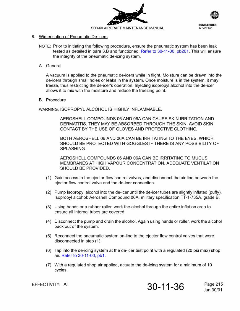
5. Winterisation of Pneumatic De-icers
NOTE: Prior to initiating the following procedure, ensure the pneumatic system has been leak tested as detailed in para 3.B and functioned. Refer to 30-11-00, pb201. This will ensure the integrity of the pneumatic de-icing system.
A. General
A vacuum is applied to the pneumatic de-icers while in flight. Moisture can be drawn into the de-icers through small holes or leaks in the system. Once moisture is in the system, it may freeze, thus restricting the de-icer's operation. Injecting isopropyl alcohol into the de-icer allows it to mix with the moisture and reduce the freezing point.
B. Procedure
WARNING: ISOPROPYL ALCOHOL IS HIGHLY INFLAMMABLE.
AEROSHELL COMPOUNDS 06 AND 06A CAN CAUSE SKIN IRRITATION AND DERMATITIS. THEY MAY BE ABSORBED THROUGH THE SKIN. AVOID SKIN CONTACT BY THE USE OF GLOVES AND PROTECTIVE CLOTHING.
BOTH AEROSHELL 06 AND 06A CAN BE IRRITATING TO THE EYES, WHICH SHOULD BE PROTECTED WITH GOGGLES IF THERE IS ANY POSSIBILITY OF SPLASHING.
AEROSHELL COMPOUNDS 06 AND 06A CAN BE IRRITATING TO MUCUS MEMBRANES AT HIGH VAPOUR CONCENTRATION. ADEQUATE VENTILATION SHOULD BE PROVIDED.
(1) Gain access to the ejector flow control valves, and disconnect the air line between the ejector flow control valve and the de-icer connection.
(2) Pump Isopropyl alcohol into the de-icer until the de-icer tubes are slightly inflated (puffy). Isopropyl alcohol: Aeroshell Compound 06A, military specification TT-1-735A, grade B.
(3) Using hands or a rubber roller, work the alcohol through the entire inflation area to ensure all internal tubes are covered.
(4) Disconnect the pump and drain the alcohol. Again using hands or roller, work the alcohol back out of the system.
(5) Reconnect the pneumatic system on-line to the ejector flow control valves that were disconnected in step (1).
(6) Tap into the de-icing system at the de-icer test point with a regulated (20 psi max) shop air. Refer to 30-11-00, pb1.
(7) With a regulated shop air applied, actuate the de-icing system for a minimum of 10 cycles.
Jun 30/0130-11-36 Page 216EFFECTIVITY: All
zSD3-60 AIRCRAFT MAINTENANCE MANUAL
(8) Shut off de-icing system and remove the shop air from the test point.
(9) Replace all panels removed in step (1) used to gain access to the ejector flow control valves.
NOTE: It is recommended that each ejector flow control valve be lubricated with a light viscosity silicone oil, approx. 100 hours after the application of isopropyl alcohol to prevent the possibility of valves sticking.
Jun 30/0130-11-41 Page 201EFFECTIVITY: All
zSD3-60 AIRCRAFT MAINTENANCE MANUAL
AMM30-11-41 13.0.0.0PRESSURE REGULATORS - MAINTENANCE PRACTICES
1. Adjustment/Test
A. Function check the pressure regulators.
(1) Refer to 6-30-00, pb1. Open access panel 312 TZ in the aft baggage compartment rear bulkhead.
(2) Install a pressure gauge 0-50 p.s.i. at the aerofoil de-icing test point.
(3) Select both BLEED switches on panel 4P SHUT.
(4) Ensure that TIMER switch is selected OFF.
(5) Refer to 71-00-00, pb1. Start both engines and run at approximately 90% Ng.
(6) Select each BLEED switch in turn to NORMAL observing that the regulated pressure shown on the gauge is between 15 and 20 p.s.i.
NOTE: If either pressure regulator operates outside these limits, it may be adjusted in situ as detailed in B.F. Goodrich Report No. 85-32-014.
(7) Shut down both engines.
(8) Remove pressure gauge and seal aerofoil de-ice test point.
(9) Close access panel 312 TZ.
Jun 30/0130-11-46 Page 201EFFECTIVITY: All
zSD3-60 AIRCRAFT MAINTENANCE MANUAL
AMM30-11-46 14.0.0.0WATER SEPARATOR - MAINTENANCE PRACTICES
1. Adjustment/Test
A. Function test the water separator.
(1) For convenience of maintenance, the water separator is function tested during pressure regulator test by checking for airflow at the overboard drain. Refer to 30-11-41, pb201.
Apr 24/0330-11-51 Page 201EFFECTIVITY: All
zSD3-60 AIRCRAFT MAINTENANCE MANUAL
AMM30-11-51 15.0.0.0PRESSURE SWITCH AND TIME DELAY RELAY - MAINTENANCE PRACTICES
1. Adjustment/Test
A. Function check the pressure switch and time delay relay.
(1) Jack the aircraft. Refer to 7-10-00, pb201.
(2) Provide electrical power. Refer to 12-09-03, pb301.
(3) Check that C/B Nos 94 and 244 on respective distribution panels 1D and 2D are closed.
(4) Operate a stop watch simultaneously with the selection of the wings and tail anti-ice TIMER switch on panel 4P, to either the 1 MIN or 3 MIN setting.
(5) Check that the time delay between the switch selection and the illumination of the SYS P amber caution light on panel 4P is approximately 60 seconds.
(6) Select the wings and tail anti-ice TIMER switch to OFF.
(7) Disconnect the electrical power.
(8) Lower the aircraft and remove the jacks. Refer to 7-10-00, pb201.
Jun 30/0130-12-00 Page 1EFFECTIVITY: All
zSD3-60 AIRCRAFT MAINTENANCE MANUAL
AMM30-12-00 16.0.0.0BOOT EJECTOR VALVE ANTI-ICING - DESCRIPTION & OPERATION
1. General
The five boot de-icer ejector valves (two left wing, two right wing and one tail) are provided with electrically heated muffs, each rated at 1.5 amps.
The muffs operate on 28V d.c., those in the left wing being fed from the left shedding busbar via C/B No. 87 on distribution panel 1D and the others from the right shedding busbar via C/B No. 237 on panel 2D.
Control switching for each circuit is facilitated by double-pole, anti-icing control switches on panel 4P (maintaining feed segregation).
2. Operation
With electrical power available and C/B Nos. 87 and 237 on respective distribution panels 1D and 2D closed, selection of the left and right PITOT/STATIC/STALL switches (panel 4P) to ON will connect the 28 dc supply to the muff elements.

Jun 30/0130-12-00 Page 201EFFECTIVITY: All
zSD3-60 AIRCRAFT MAINTENANCE MANUAL
AMM30-12-00 17.0.0.0BOOT EJECTOR VALVE ANTI-ICING - MAINTENANCE PRACTICES
1. Adjustment/Test
A. Function check heater muffs
(1) Hinge down flight compartment roof panel 4P
(2) Refer to 12-09-03, pb301. Provide electrical power.
(3) Close C/B Nos. 87 and 237 on respective distribution panels 1D and 2D
(4) Check operation of left wing heater muffs and related control switch on panel 4P as follows:-
(a) With the left PITOT/STATIC/STALL switch selected OFF connect the probes of a test meter across terminals 5 and 6 of the switch and check that a reading of approximately 3 amps is obtained i.e. both left wing heater muffs functional.
(b) Select switch ON momentarily, checking that test meter registers zero (direct feed to heaters).
(5) Check operation of tail and right wing heater muffs and related control switch on panel 4P as follows:-
(a) With the right PITOT/STATIC/STALL switch selected OFF connect the probes of a test meter across terminals 5 and 6 of the switch and check that a reading of approximately 4.5 amps is indicated i.e. tail and both right wing heater muffs are functional.
(b) Select switch ON momentarily, checking that test meter registers zero (direct feed to heaters).
(6) Close panel 4P.
Jun 30/0130-20-00 Page 1EFFECTIVITY: All
zSD3-60 AIRCRAFT MAINTENANCE MANUAL
AMM30-20-00 18.0.0.0ENGINE AIR INTAKE ANTI-ICING - GENERAL
1. General
The aircraft is provided with an engine air intake anti-icing system, details of which appear in the following sections.
A. Engine air intake anti-icing (Pre mod A8170). Refer to 31-21-10, pb1.
B. Engine air intake anti-icing (Post mod A8170 or post Service Bulletin SD360-30-17). Refer to 30-21-20, pb201.
C. Intake inertial anti-icing. Refer to 30-22-00, pb201.
Jun 30/0131-21-10 Page 1EFFECTIVITY: All
zSD3-60 AIRCRAFT MAINTENANCE MANUAL
AMM31-21-10 19.0.0.0ENGINE AIR INTAKE ANTI-ICING - DESCRIPTION & OPERATION(PRE MOD A8170)
1. Description
A. General
A Dunlop AC1192 heater mat is installed on the lip of each air intake cowl and is operationally controlled within the temperature range 70°C to 80°C.
Each circuit essentially comprises:-
(1) an INTAKES heat control switch on ANTI ICING panel 4P
(2) a thermal controller on panel 3C - left, 4C - right
(3) a remote control circuit breaker located at wing station 20, left and right, in the engine support structure
(4) a lip-installed temperature sensor, integral to the heater unit.
Indication of current flow is provided by a current sensing relay in each heating circuit, illuminating the ON caption situated above each control switch.
B. Heating mats
Each heating mat consists of copper alloy foil elements (approximately .005 in. thick) encapsulated in a coating of flexible resin, sandwiched between layers of glass fabric and impregnated with high temperature resin. The heater is applied directly to the lip of the intake structure to form an integral part of the intake. Temperature control is by means of a temperature sensor installed in the base layers of the insulation. The surface of each heater is protected against weather erosion or impact damage by a coating of Erocoat Black. This is electrically conductive and will dissipate any static electrical charges which may build up on the surface of the heater.
C. Thermal Controllers
The thermal controllers mounted on the engine air intake panels 3C (left) and 4C (right) operate in conjunction with the temperature sensors to control the supplies to the heaters.
2. Operation
When the INTAKES switches on ANTI-ICING panel 4P are selected ON, each thermal controller connects a 28V d.c. supply to the intake heater via a remote control circuit breaker and current sensing relay.
Jun 30/0131-21-10 Page 2EFFECTIVITY: All
zSD3-60 AIRCRAFT MAINTENANCE MANUAL
Should the lip temperature reach 80°C the temperature sensor will signal the thermal controller to de-energise the remote control circuit breaker, thus interrupting the heater supply. The absence of flow through the current sensing relay will cause the contacts to open, extinguishing the ON caption on panel 4P.
The supply will be restored when the lip temperature falls to 70°C.
3. Power Supplies
Power supplies for control and indication are respectively taken from the 28V DC SHEDDING BUSBARS (LEFT and RIGHT) via circuit breakers Nos. 23 and 95 (panel 1D) and Nos. 173 and 245 (panel 2D). Heater power supplies are derived from the MAIN busbars via two remote control circuit breakers. Control of the remote circuit breakers is afforded by C/B Nos 11A and 161A, located on panels 1D and 2D respectively.
Apr 24/0330-21-10 Page 201EFFECTIVITY: All
zSD3-60 AIRCRAFT MAINTENANCE MANUAL
AMM30-21-10 20.0.0.0ENGINE AIR INTAKE ANTI-ICING - MAINTENANCE PRACTICES (PRE MOD A8170)
1. Adjustment/Test
A. Function test the system
(1) Gain access to the engine air intake heater terminal blocks by lowering air intake cowl 420BB on each engine. Refer to 6-30-00, pb1.
(2) Apply an Avometer across air intake heaters at 1ATB1 (terminals 1 & 2) and check that the resistance is within 0.250Ω and 0.263Ω.
NOTE: If any one element is open circuit the reading will be in excess of 0.350Ω.
(3) Open circuit breakers Nos. 11A, 23 and 95 on distribution panel 1D and 161A, 173 and 245 on distribution panel 2D.
(4) Select both INTAKES switches on panel 4P OFF.
(5) Energise LEFT and RIGHT 28V D.C. MAIN and SHEDDING busbars from an external supply. Refer to 12-09-03, pb301.
(6) Close AIR INTAKE INDICATION circuit breaker No. 95 on panel 1D and check that there is no display on the left INTAKES indicator.
(7) Close ENG INTAKE HEATER and ENGINE AIR INTAKE-HEAT CONTROL circuit breakers Nos. 11A and 23 on panel 1D.
CAUTION: HEAT SHOULD ONLY BE RETAINED ON FOR 20 SECONDS.
(8) Select left INTAKES switch on panel 4P ON and check that:-
(a) the INTAKES indicator displays ON
(b) the VANE L segment of the annunciator on the Central Warning Panel is illuminated
NOTE: select the left ANTI-ICE VANES switch to ON, then OFF and check that the VANE L segment of the annunciator respectively extinguishes and illuminates again
(c) the left hand heater mat surface is warm with the highest temperature at the leading edge.
(9) Select left INTAKES switch OFF and check that indications are extinguished and heat is off.
Equipment required : Avometer
Apr 24/0330-21-10 Page 202EFFECTIVITY: All
zSD3-60 AIRCRAFT MAINTENANCE MANUAL
(10) Select left INTAKES switch ON and check that indicator cycles ON and OFF. Allow two cycles only before selecting switch OFF.
(11) Select left INTAKES switch ON and ensure that ON indication is illuminated. Momentarily apply a 28V DC feed at A1TB2 terminal 3 (left engine) and check that system trips off i.e. indication is extinguished.
(12) Select left INTAKES switch OFF then ON and check that ON indication is again illuminated.
(13) Select left switch OFF.
(14) Repeat tests (2) to (13) inclusive for right engine substituting right for left and circuit breakers 245 for 95, 161A for 11A and 173 for 23.
(15) Close both engine cowls.
Jun 30/0130-21-20 Page 1EFFECTIVITY: All
zSD3-60 AIRCRAFT MAINTENANCE MANUAL
AMM30-21-20 21.0.0.0ENGINE AIR INTAKE ANTI-ICING - DESCRIPTION & OPERATION(POST MOD A8170 OR POST SERVICE BULLETIN SD360-30-17)
1. Description
A. General
A Dunlop AC1192 heater mat is installed on the lip of each air intake cowl and is operationally controlled within the temperature range 70°C to 80°C.
Each circuit essentially comprises:-
(1) an INTAKES heat control switch and indicator on the ANTI-ICING section of panel 4P.
(2) a thermal controller on panel 3C-left, 4C-right.
(3) a remote control circuit breaker, located at wing station 20, left and right, in the engine support structure.
(4) an intake heater unit with integral temperature sensor.
(5) a current sensing relay to provide ON indication.
(6) a contactor and associated slave relay to provide cycling of the heater unit.
B. Heating mats
Each heating mat consists of copper alloy foil elements (approximately .005 in. thick) encapsulated in a coating of flexible resin, sandwiched between layers of glass fabric and inpregnated with high temperature resin. The heater is applied directly to the lip of the intake structure to form an integral part of the intake. Temperature control is by means of a temperature sensor installed in the base layers of the insulation. The surface of each heater is protected against weather erosion or impact damage by a coating of Erocoat Black. This is electrically conductive and will dissipate any static electrical charges which may build up on the surface of the heater.
C. Thermal Controllers
The thermal controllers are mounted on the engine air intake panels 3C (left) and 4C (right) operate in conjunction with the temperature sensors to control the supplies to the heaters.
2. Operation
When the INTAKE switch on panel 4P is selected to ON, 28V dc is supplied to the control unit. The control unit in turn energizes the control contactor via the auxiliary contacts of its slave relay. Power will then be supplied to the heater unit via the remote control circuit breaker and the current sensing relay, which energizes to provide an ON indication on panel 4P.
Jun 30/0130-21-20 Page 2EFFECTIVITY: All
zSD3-60 AIRCRAFT MAINTENANCE MANUAL
Should the temperature reach 80°C, the temperature sensor will signal the control unit to de-energize the slave relay, thereby breaking the supply to the coil of the control contactor. The absence of flow of current through the current sensing relay will cause its contacts to open, extinguishing the ON indication on panel 4P.
When the temperature drops to 70°C, the temperature sensor signals the control unit to re-energize the slave relay and energize the control contactor, thereby reconnecting the supply to the heater.
3. Power Supplies
Power supplies for control and indication are taken from the LEFT and RIGHT 28V DC SHEDDING busbars via 3 amp C/B Nos 23 and 173 on panels 1D and 2D respectively. Supplies to the heater are taken from the LEFT and RIGHT 28V DC MAIN busbars via the remote control circuit breakers, control of which is afforded by 0.5 amp C/B Nos. 11A and 161A on panels 1D and 2D respectively.
Apr 24/0330-21-20 Page 201EFFECTIVITY: All
zSD3-60 AIRCRAFT MAINTENANCE MANUAL
AMM30-21-20 22.0.0.0ENGINE AIR INTAKE ANTI-ICING - MAINTENANCE PRACTICES(POST MOD A8170 OR POST SERVICE BULLETIN SD360-30-17)
1. Adjustment/Test
A. Function test the system
(1) Gain access to the engine air intake heater terminal blocks by lowering air intake cowl 420BB on each engine. Refer to 6-30-00, pb1.
(2) Apply an avometer across air intake heaters at A1TB1 (terminals 1 & 2) and check that the resistance is within 0.250Ω and 0.263Ω.
NOTE: If any one element is open circuit the reading will be in excess of 0.350Ω.
(3) Open C/B Nos. 11A and 23 on distribution panel 1D and 161A and 173 on distribution panel 2D.
(4) Select both INTAKES switches on panel 4P to OFF.
(5) Energise LEFT and RIGHT 28V D.C. MAIN and SHEDDING busbars from an external supply. Refer to 12-09-03, pb301.
(6) Close C/B Nos. 11A and 23 on panel 1D.
CAUTION: HEAT SHOULD ONLY BE RETAINED ON FOR 20 SECONDS.
(7) Select left INTAKES switch on panel 4P to ON and check that:-
(a) the INTAKES indicator displays ON
(b) the VANE L segment of the annunciator on the Central Warning Panel is illuminated
NOTE: select the left ANTI-ICE VANES switch to ON, then OFF and check that the VANE L segment of the annunciator respectively extinguishes and illuminates again
(c) the left hand heater mat surface is warm with the highest temperature at the leading edge.
(8) Select left INTAKES switch OFF and check that indications are extinguished and heat is off.
(9) Select left INTAKES switch ON and check that the indicator cycles ON and OFF. Allow two cycles only before selecting switch OFF.
Equipment required: Avometer28V DC Power Supply
Apr 24/0330-21-20 Page 202EFFECTIVITY: All
zSD3-60 AIRCRAFT MAINTENANCE MANUAL
(10) Select the left INTAKES switch to ON and ensure that the ON indication is illuminated. Momentarily apply a 28V DC feed at A1TB2 terminal 3 (left engine) and check that system trips off i.e. indication is extinguished.
(11) Select the left INTAKES switch OFF, then ON and check that the ON indication is again illuminated.
(12) Select the left INTAKES switch to OFF.
(13) Repeat tests (2) to (13) inclusive for right engine substituting right for left and circuit breakers 161A for 11A and 173 for 23.
(14) Close both engine cowls.
Apr 24/0330-22-00 Page 1EFFECTIVITY: All
zSD3-60 AIRCRAFT MAINTENANCE MANUAL
AMM30-22-00 23.0.0.0INTAKE INERTIAL ANTI-ICING - DESCRIPTION & OPERATION
1. Description
A. General
An electrical actuator functioned arrangement within each engines air intake cowl is operationally deployed to prevent ice and snow particles from clogging/entering the compressor inlet screen.
The arrangement essentially comprises two mechanically linked vanes the forward and aft of which respectively operate as an airflow deflector and particle overboard discharge door.
Advantage of the system as an automatic drag limiting device should the associated engine fail when both engines were operating in the take-off range is taken.
B. Controls and Indication
(1) Anti-icing
Two ANTI-ICE VANES switches are provided on panel 4P; captioned indicator modules above each are controlled by travel limit switches within the associated actuator and display:-
(2) Drag limiting
A relay, circuit-idented 'CF' is located on each of respective left and right equipment panels 1C and 2C. When energised in circumstances detailed in para. 2.B., the relay will override a system OFF selection.
(3) Ice Vane system off warning
The Ice Vane annunciator system on the Central Warning Panel (CWP) links with the Engine Air Intake Anti-icing and Propeller De-icing systems, to indicate if the vanes (one on each engine) are not in the ANTI-ICE position when the other anti-ice systems are selected ON. The caption of the annunciator shows VANE L or VANE R (black letters on amber background), to alert the flight crew to the Intake Inertial ANTI-ICE VANE which has not been selected ON (panel 4P).
NORM:(green letters on black background)
System OFF (deflector vane retracted)
'out': Actuator in transit/power offANTI-ICE:(white letters on black background)
System ON (deflector vane extended)
Apr 24/0330-22-00 Page 2EFFECTIVITY: All
zSD3-60 AIRCRAFT MAINTENANCE MANUAL
C. Power supplies
Actuator power supplies are derived from the 28V dc left and right General Services busbars via C/B Nos 24 and 174 on respective distribution panels 1D and 2D.
Drag limiting relay control supply is taken from the propeller autofeathering circuitry. Refer to 61-22-00, pb1.
Ice Vane annunciation power supplies are taken from the 28V dc left Shedding busbar via C/B Nos 8 and 23, and from the right Shedding busbar via C/B Nos 158 and 173 on respective distribution panels 1D and 2D.
2. Operation
A. Anti-ice function
When a control switch is selected ON, the associated actuators retracts, thus respectively lowering and raising the forward and aft vanes as shown on the lower diagram. Refer to Figure 1.
Acceleration of the inlet flow as a result of lowering the forward vane will cause air/particle separation - air being directed into the compressor and ice and snow particles (under increased momentum) overboard through the now open ducting at the rear of the intake.
An ice shredder bridge which spans the intake duct adjacent to the aft vane acts as an ice accumulator. The ice build-up on the shredder subsequently cracks and is carried overboard by the scavenging effect of the airstream.
When the control switch is selected OFF, the vane arrangement and airflow will be as shown on the upper diagram. Refer to Figure 1.
B. Auto-deployment (drag limiting):
Should an engine failure occur whilst both were operating in the take-off range (power levers set for 88% Ng or greater), initiation of propeller autofeathering on the failed side will additionally energise the related CF relay such an anti-ice vane OFF selection will be overridden. Refer to 61-22-00, pb201. The vanes will then auto-deploy to the system ON condition, the resultant 'through airflow' thus further diminishing power plant drag in association with propeller feathering.
NOTE: Procedurally, the pilot will select the appropriate ANTI-ICE VANE switch ON before subsequent movement of either power to a position below 88%Ng.
C. Ice Vane system off warning
Selection of the ANTI-ICING left or right engine INTAKES or PROPELLERS switch on panel 4P will energise the associated ICE VANE relay, 28V dc being taken from the Left or Right Shedding Busbar to close the relay contacts.
Apr 24/0330-22-00 Page 3EFFECTIVITY: All
zSD3-60 AIRCRAFT MAINTENANCE MANUAL
If the ANTI-ICE VANES switch is in the OFF (NORM caption illuminated) position at this time, 28V dc is routed to the CWP, via the energised relay(s) illuminating the associated segment of the VANE L / VANE R annunciator.In the NORM position, each system actuator is fully extended against the integral electrical limit switch, holding it in a closed position. When the ANTI-ICE VANES switch is selected ON (ANTI ICE caption illuminated), the associated actuator retracts and immediately opens the integral extend limit switch. This instantaneously removes 28V dc power from both the associated segment of the VANE L / VANE R annunciator and the NORM caption, extinguishing both.

Apr 24/0330-22-00 Page 4EFFECTIVITY: All
zSD3-60 AIRCRAFT MAINTENANCE MANUAL
Intake Inertial Anti-icingFigure 1
Apr 24/0330-22-00 Page 201EFFECTIVITY: All
zSD3-60 AIRCRAFT MAINTENANCE MANUAL
AMM30-22-00 24.0.0.0INTAKE INERTIAL ANTI-ICING - MAINTENANCE PRACTICES
1. Adjustment/Test
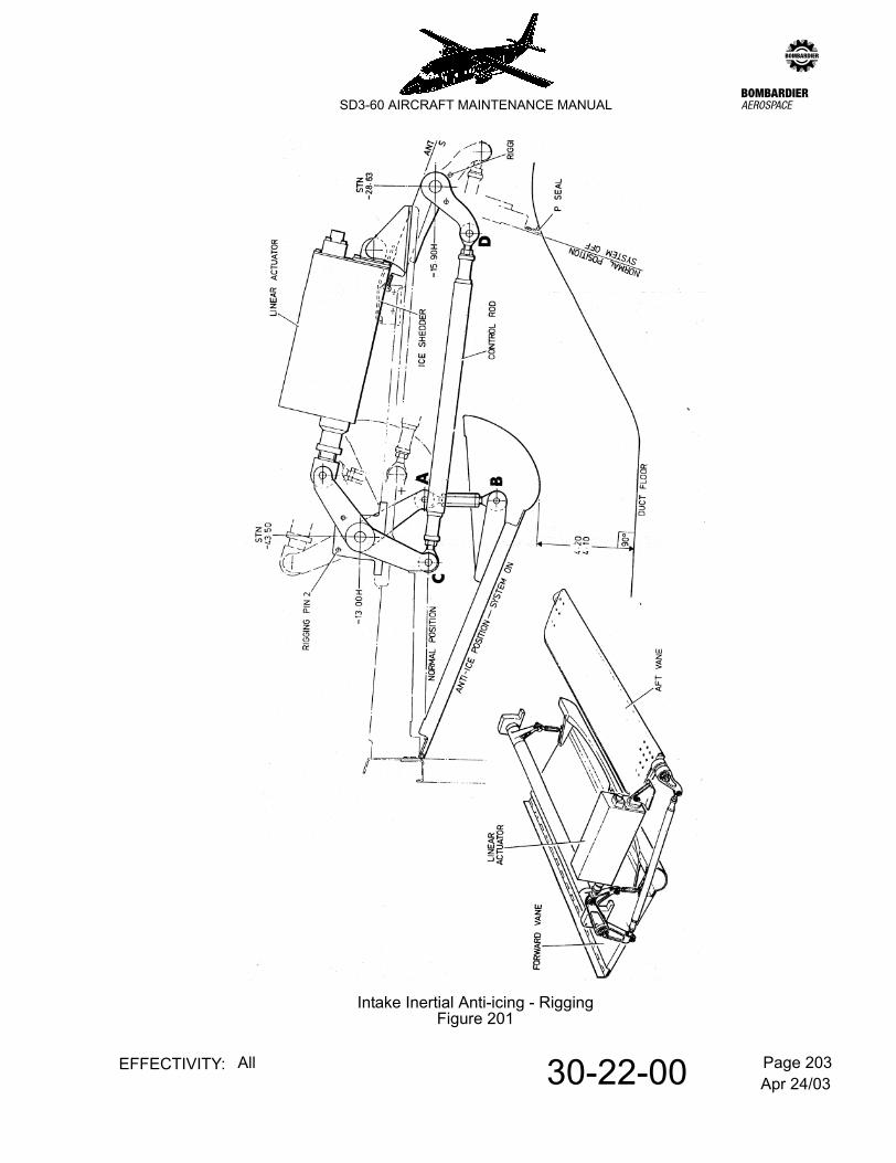
A. Rig the aft intake vane
Refer to Figure 201.
Rigging is carried out with the linear actuator disconnected.
(1) Check by manual operation, that the aft vane moves freely throughout its range of travel and seals off the rear of the duct when fully closed i.e. the 'P' seal is compressed between the periphery of the vane and the duct.
(2) Hold the aft vane in the fully closed position and insert rigging pin No. 1 through the operating lever.
(3) Place the forward operating lever in the system OFF position and insert rigging pin No. 2.
(4) Adjust the control rod, maintaining the threaded adjusters 'in safety' and connect the forward and aft operating levers at points C & D. Tighten locknuts and secure with tab washers.
B. Rig the linear actuator
(1) Place the forward operating lever in the System OFF position and insert rigging pin No. 2.
(2) Refer to 12-09-03, pb301. Energise the left or right 28 V D.C. general services busbar as applicable.
(3) Close circuit breaker No. 24 on panel 1D (left intake) or circuit breaker No. 174 on panel 2D (right intake) as appropriate.
(4) Select the appropriate ANTI-ICE VANES switch OFF to 'motor out' the linear actuator until the actuator/lever pivot holes are aligned.
NOTE: The adjustable eye on the end of the actuator plunger may be used to align the pivot holes maintaining the threads in safety. Ensure that locknut is re-tightened.
(5) Remove rigging pin No. 2 and select the appropriate ANTI-ICE VANES switch ON to 'motor in' the linear actuator. Check that the 'P' seal on the aft vane touches the centre portion of the ice shredder.
(6) Refer to 20-09-06, pb1. Torque tighten the pivot bolt securing nut and fit split pin.
(7) Switch off the power supply.

Apr 24/0330-22-00 Page 202EFFECTIVITY: All
zSD3-60 AIRCRAFT MAINTENANCE MANUAL
C. Rig the forward intake vane.
(1) Refer to 12-09-03, pb301. Energise the left or right 28V D.C. general services busbar as applicable.
(2) Close circuit breaker No. 24 on panel 1D (left intake) or circuit breaker No. 174 on panel 2D (right intake) as appropriate.
(3) Select the appropriate ANTI-ICE VANES switch ON and check the position of the aft vane - para B.(5).
(4) Connect the adjustable links at points A & B to provide a clearance between the lowest point on the vane curve and the bottom of the duct of 4.20 in/4.10 in. Ensure that the threads on the adjustable links are "in safety" and tighten the locknuts.
(5) Switch off power supply.
D. Function check the anti-icing vane mechanism.
Perform the following as appropriate to left or right system:-
(1) Refer to 12-09-03, pb301. Energise the 28V D.C. general services busbars.
(2) Ensure appropriate C/B No. 24 - panel 1D (left intake) or 174 - panel 2D (right intake) is closed.
(3) Select the relevant ANTI-ICE VANE control switch (panel 4P) to ON and check that:
(a) the forward vane in the related intake is lowered to within 4.2 in. to 4.1 in. from the bottom of the duct and the rear vane is raised to close off the aperture to the ice shedder with the 'P' seal touching the radiused centre portion.
(b) the associated indicator module on panel 4P displays ANTI-ICE.
(c) the associated VANE L / VANE R segment of the annunciator on the Central Warning Panel remains extinguished.
(4) Select the control switch OFF, checking that
(a) the forward vane retracts flush with the top of the duct and the aft vane closes against the rear of the duct.
(b) the indicator module now displays NORMal.
Apr 24/0330-22-00 Page 203EFFECTIVITY: All
zSD3-60 AIRCRAFT MAINTENANCE MANUAL
Intake Inertial Anti-icing - RiggingFigure 201
Apr 24/0330-22-00 Page 204EFFECTIVITY: All
zSD3-60 AIRCRAFT MAINTENANCE MANUAL
(5) Check auto-deployment function (drag limiting) as follows:-
NOTE: Both intake arrangements may be checked simultaneously as undernoted.
(a) Ensure autofeather system C/B Nos.20 and 170 on respective distribution panels 1D and 2D are closed.
(b) With both systems selected OFF and NORMAL displayed, hold the AUTO FEATHER test switches on panel 11P at TEST, checking:-
1 NORMAL indications are extinguished i.e. anti-icing mechanism in transit.
2 Systems revert to NORMAL when test switches are released.
Jun 30/0130-31-00 Page 1EFFECTIVITY: All
zSD3-60 AIRCRAFT MAINTENANCE MANUAL
AMM30-31-00 25.0.0.0PITOT/STATIC ANTI ICING SYSTEM - DESCRIPTION & OPERATION
1. Description
A. General
Anti-icing protection for the pitot heads and static vents of the Pitot/Static system (Refer to 34-11-00, pb1.) is afforded by 28V d.c. heater elements within each unit.
Separate power supplies, control and indication facilities are accorded to the left and right installations, each of which basically comprises the elements of a pitot head and two static vents.
B. Control and indication
System control is by two ON/OFF switches on panel 4P idented PITOT/STATIC/STALL.
NOTE: Switching facilities are shared with the boot ejector valve anti-icing system. Refer to 30-12-00, pb1.
Indication of current flow to the static vents and pitot heads is signalled by current sensing relays in each heating circuit. The indicator for each pair of STATIC vents (left and right) is situated above the related control switch on panel 4P and the PITOT L/PITOT R heater failure lights are on the centralized warning panel 1P.
2. Operation
With appropriate power supplies available, a heater group will operate when the associated control switch on panel 4P is selected ON. Satisfactory function of the static vent heaters is confirmed by illumination of the STATIC indicator on panel 4P.
The relevant PITOT L/PITOT R warning light will be illuminated prior to the selection of the related control switch to ON. When the control switch is selected ON the current sensing relay will operate, thus interrupting the supply to the warning light.
Conversely, operational failure of a pitot head heater (no current flow) will cause illumination of the warning light.
3. Power supplies
Power supplies for heater operation are taken from the LEFT and RIGHT 28V D.C. MAIN busbars via 10 amp circuit breaker Nos. 22 and 172 on respective distribution panels 1D and 2D.
Pitot heater warning light supplies are derived from the LEFT and RIGHT 28V D.C. ESSENTIAL SERVICES busbar via 5 amp. circuit breakers Nos. 21 and 171 on distribution panels 1D and 2D respectively.
Jun 30/0130-31-00 Page 201EFFECTIVITY: All
zSD3-60 AIRCRAFT MAINTENANCE MANUAL
AMM30-31-00 26.0.0.0PITOT/STATIC ANTI-ICING SYSTEM - MAINTENANCE PRACTICES
1. Adjustment/Test
A. Function check
(1) Select both PITOT/STATIC/STALL switches OFF.
(2) Energise LEFT and RIGHT 28V D.C. MAIN and ESSENTIAL SERVICES busbars from an external supply.
(3) Ensure that circuit breaker Nos.21 and 22 (panel 1D) and 171 and 172 (panel 2D) are closed.
(4) Check that both PITOT L and PITOT R captions on centralized warning panel 1P are illuminated.
(5) Select both PITOT/STATIC/STALL switches ON and check that:
(a) both STATIC indicators (panel 4P) are illuminated
(b) both PITOT L and PITOT R captions (panel 1P) are extinguished.
(6) Select both PITOT/STATIC/STALL switches OFF and check that:-
(a) both STATIC indicators are black
(b) both PITOT L and PITOT R captions are again illuminated.
Jun 30/0130-40-00 Page 1EFFECTIVITY: All
zSD3-60 AIRCRAFT MAINTENANCE MANUAL
AMM30-40-00 27.0.0.0WINDSHIELDS - GENERAL
1. General
Weather protection for the pilots windshield consists of:
A. Electrically heated windshield. Refer to 30-41-00, pb1.
B. Windshield wipers. Refer to 30-42-00, pb1.
C. A rain repellent system. Refer to 30-43-00, pb1.
Jun 30/0130-41-00 Page 1EFFECTIVITY: All
zSD3-60 AIRCRAFT MAINTENANCE MANUAL
AMM30-41-00 28.0.0.0HEATED WINDSHIELD - DESCRIPTION & OPERATION
1. General
Both forward facing windshield panels are provided with controlled electrical heat for ice prevention. The heat output from each is regulated by individual thermal controllers, operating in conjunction with associated control switches, indicators and supply (normal and overheat) relays. Power supplies are taken from the 28V DC Main busbars, left and right.
2. Description
The windshield comprises three stretched acrylic plies and a strengthened glass (0.1 in. thickness) outer ply laminated together. The heating element is 'sandwiched' in the windshield laminations.
Windshield electrical connections are by terminal blocks bonded to the bottom of the windshield.
A. Thermal controller
Heat control is provided by a Lucas Mk. 12 controller. Resistance bridge networks in the controller are brought to electrical balance at specified temperature control points as a result of a change of resistance detected by thermistors with temperature. The out of balance signals are detected, amplified and caused to operate miniature relays whose contacts are used to operate the normal and overheat relays, thereby switching the supply to the windshield. Generally, only the normal control channel operates to control the supply to the windshield. The overheat channel operates only as a result of a fault condition developing in the normal channel or associated components.
B. Power supplies
Power supplies for each windshield are derived from the left and right 28V DC Main busbars respectively taken via circuit breakers CB112 and CB113 (panel 1D) and circuit breakers CB248 and CB249 (panel 2D).
C. Indication
Indication for each windshield is afforded by a switch/indicator module situated on panel 4P the upper half of which indicates the NORMal heat cycle and lower half OverHEAT.
3. Operation
A. NORMal
With the appropriate circuit breakers closed and the WINDSHIELDS heat switch selected ON power will be transmitted through the normal and overheat relays to the windshield.
Jun 30/0130-41-00 Page 2EFFECTIVITY: All
zSD3-60 AIRCRAFT MAINTENANCE MANUAL
The associated switch/indicator module will illuminate NORMal only during heat transmission i.e. until the supply is automatically switched off by the thermal controller (normal relay open) when a windshield temperature of 39°C is sensed. The normal channel relay will close to restore the heating circuit when the windshield temperature falls to 31°C. The system will continue to cycle in this manner until switched off.
B. O'HEAT
An overheat condition is provided for, in that should the system, through fault, exceed the maximum temperature in the normal range (39°C) and reach 60°C the overheat relay will open in response to the thermal controller, automatically switching off the supply. Both O'HEAT and NORMal captions will be illuminated during heat transmission in the overheat range (39°C - 60°C), the O'HEAT cycling off each time a windshield temperature of 60°C is sensed. The system will continue to cycle in this manner until switched off or the fault rectified.
C. Overheat test switches
Two windshield overheat PRESS TO TEST switches incorporated in the switch/indicator modules for right and left services are provided to function check each of the overheat thermistors in the windshields. Overheat test is initiated by depressing the switch/indicator and should only be applied when the normal channel has cycled 'off' (NORMal caption extinguished). The test will be confirmed satisfactory by the illumination of the O'HEAT caption.
Jan 31/1130-41-00 Page 201EFFECTIVITY: All
zSD3-60 AIRCRAFT MAINTENANCE MANUAL
AMM30-41-00 29.0.0.0HEATED WINDSHIELD - MAINTENANCE PRACTICES
1. Removal/Installation
A. Remove a windscreen
(1) Isolate power supply to windshield by opening CB112 and CB113 (left) or CB248 and CB249 (right) as appropriate, on distribution panels 1D or 2D respectively.
(2) Gain access to associated windshield terminal block, idented 1HH9 (left) or 2HH9 (right), and disconnect terminals P2, N1, N2, O2, O1 and P1.
NOTE: On aircraft with Triplex windshields fitted as alternative to Lucas, terminal SD should also be disconnected.
(3) Refer to Structural Repair Manual, Chapter 56 for details of windshield removal.
B. Install a Windshield
(1) Install the windshield. Refer to SRM, 56-10-00.
(2) Connect appropriate terminals P2, N1, N2, O2, O1 and P1 to windshield terminal block.
NOTE: Make sure terminal P2 is connected as detailed in the SRM, section 56-00-00, Figure 3, to prevent a foul condition.
On aircraft with Triplex windshields fitted as alternative to Lucas, terminal SD should also be connected.
Lucas winsheild terminals should be tightened using torque spanner Pt. No. 41762-411-0; this is obtainable from:-
Dowty InterconnectKnaves Beech Business CentreLoudwaterHigh WycombeBuckinghamshire, HP10 9UTENGLAND
Telephone: +44 (0) 1628 810810
Fax: +44 (0) 1628 810813
(3) Perform function check as detailed in para. 2.A.
Jan 31/1130-41-00 Page 202EFFECTIVITY: All
zSD3-60 AIRCRAFT MAINTENANCE MANUAL
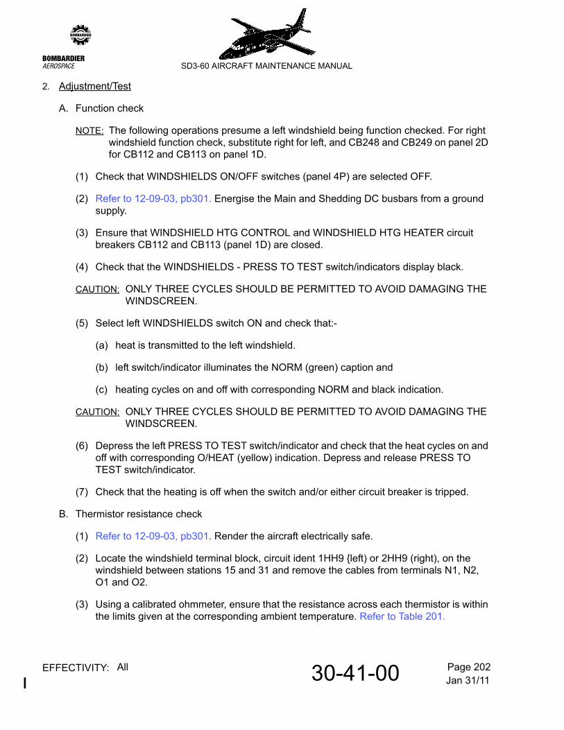
2. Adjustment/Test
A. Function check
NOTE: The following operations presume a left windshield being function checked. For right windshield function check, substitute right for left, and CB248 and CB249 on panel 2D for CB112 and CB113 on panel 1D.
(1) Check that WINDSHIELDS ON/OFF switches (panel 4P) are selected OFF.
(2) Refer to 12-09-03, pb301. Energise the Main and Shedding DC busbars from a ground supply.
(3) Ensure that WINDSHIELD HTG CONTROL and WINDSHIELD HTG HEATER circuit breakers CB112 and CB113 (panel 1D) are closed.
(4) Check that the WINDSHIELDS - PRESS TO TEST switch/indicators display black.
CAUTION: ONLY THREE CYCLES SHOULD BE PERMITTED TO AVOID DAMAGING THE WINDSCREEN.
(5) Select left WINDSHIELDS switch ON and check that:-
(a) heat is transmitted to the left windshield.
(b) left switch/indicator illuminates the NORM (green) caption and
(c) heating cycles on and off with corresponding NORM and black indication.
CAUTION: ONLY THREE CYCLES SHOULD BE PERMITTED TO AVOID DAMAGING THE WINDSCREEN.
(6) Depress the left PRESS TO TEST switch/indicator and check that the heat cycles on and off with corresponding O/HEAT (yellow) indication. Depress and release PRESS TO TEST switch/indicator.
(7) Check that the heating is off when the switch and/or either circuit breaker is tripped.
B. Thermistor resistance check
(1) Refer to 12-09-03, pb301. Render the aircraft electrically safe.
(2) Locate the windshield terminal block, circuit ident 1HH9 left) or 2HH9 (right), on the windshield between stations 15 and 31 and remove the cables from terminals N1, N2, O1 and O2.
(3) Using a calibrated ohmmeter, ensure that the resistance across each thermistor is within the limits given at the corresponding ambient temperature. Refer to Table 201.
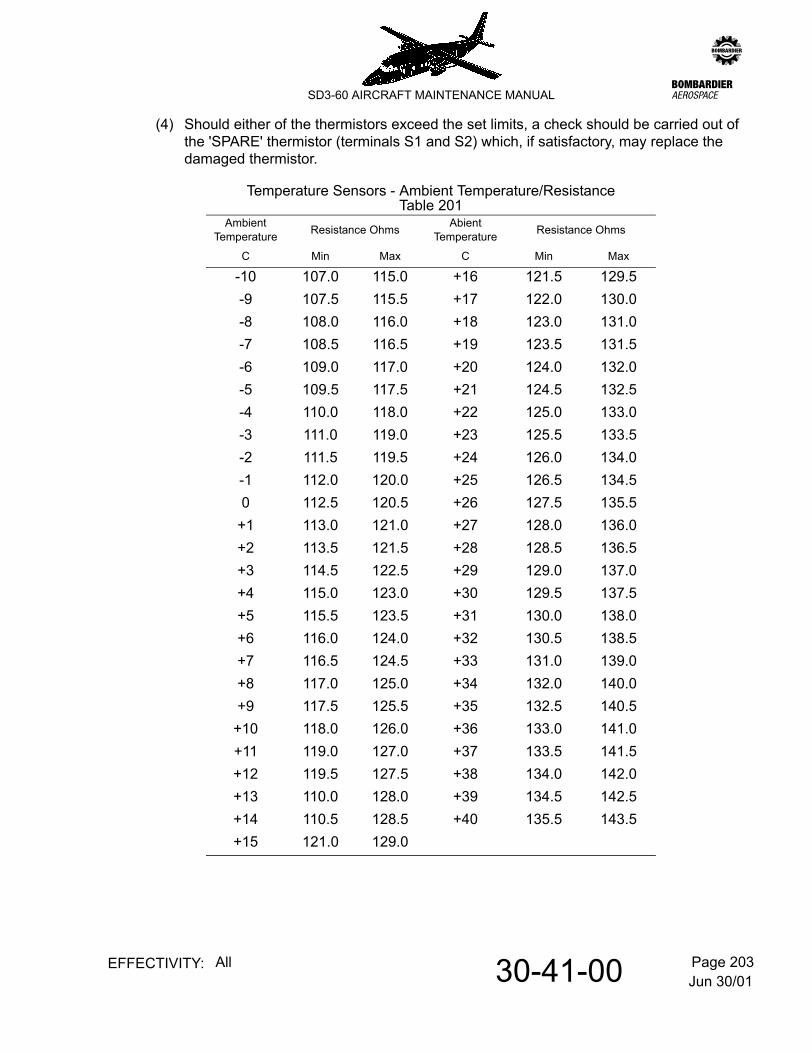
Jun 30/0130-41-00 Page 203EFFECTIVITY: All
zSD3-60 AIRCRAFT MAINTENANCE MANUAL
(4) Should either of the thermistors exceed the set limits, a check should be carried out of the 'SPARE' thermistor (terminals S1 and S2) which, if satisfactory, may replace the damaged thermistor.
Temperature Sensors - Ambient Temperature/ResistanceTable 201
AmbientTemperature Resistance Ohms Abient
Temperature Resistance Ohms
C Min Max C Min Max
-10 107.0 115.0 +16 121.5 129.5-9 107.5 115.5 +17 122.0 130.0-8 108.0 116.0 +18 123.0 131.0-7 108.5 116.5 +19 123.5 131.5-6 109.0 117.0 +20 124.0 132.0-5 109.5 117.5 +21 124.5 132.5-4 110.0 118.0 +22 125.0 133.0-3 111.0 119.0 +23 125.5 133.5-2 111.5 119.5 +24 126.0 134.0-1 112.0 120.0 +25 126.5 134.50 112.5 120.5 +26 127.5 135.5
+1 113.0 121.0 +27 128.0 136.0+2 113.5 121.5 +28 128.5 136.5+3 114.5 122.5 +29 129.0 137.0+4 115.0 123.0 +30 129.5 137.5+5 115.5 123.5 +31 130.0 138.0+6 116.0 124.0 +32 130.5 138.5+7 116.5 124.5 +33 131.0 139.0+8 117.0 125.0 +34 132.0 140.0+9 117.5 125.5 +35 132.5 140.5
+10 118.0 126.0 +36 133.0 141.0+11 119.0 127.0 +37 133.5 141.5+12 119.5 127.5 +38 134.0 142.0+13 110.0 128.0 +39 134.5 142.5+14 110.5 128.5 +40 135.5 143.5+15 121.0 129.0
Jun 30/0130-42-00 Page 1EFFECTIVITY: All
zSD3-60 AIRCRAFT MAINTENANCE MANUAL
AMM30-42-00 30.0.0.0WINDSHIELD WIPERS - DESCRIPTION & OPERATION
1. Description
A. General
Two independent electro-mechanical type wiper installations are provided; one at each pilots position. Each installation essentially is comprised of a motor coupled to a converter, drive arm and blade assembly.
B. Motor
The drive motor, identified 1MA3 (left hand) and 2MA3 (right hand) is a conventional enclosed series wound unit with a thermal cut-out to provide for an overheat condition.
C. Converter
The converter, attached to a common support fitting with the motor, reduces the motor RPM and transforms the rotary force of the motor into a reciprocating motion to drive the wiper blade. Each revolution of the converter gearing produces two strokes of the wiper blade (1 cycle); one in each direction. The converter has a worm shaft which can be driven from either end and is adaptable for LH or RH installation.
D. Drive arm/blade assembly
The drive arm/blade assembly engages on the splined shaft of the converter unit where it protrudes through the aircraft skin to provide the required blade sweep on the windshield. The drive arm and blade assembly is blackened to minimise glare.
A tension spring is enclosed in the drive arm and is attached to a point adjacent to the converter drive shaft to provide the correct blade pressure on the windshield.
E. Controls
Each wiper unit is controlled by a separate three-position switch, ON/OFF/PARK, located on panel 1P.
A two speed wiper facility is available by selection of a FAST/SLOW switch adjacent to the WIPER control switch.
2. Operation
With the electrical power provided, circuit breakers closed, selection of the appropriate WIPER control switch will cause the wiper blade to operate. Selection of FAST/SLOW switches will provide wiper speeds of approximately 170 and 100 cycles per minute.
Upon depression of wiper control switch to PARK, the wiper blade will stop at the outboard edge of the windshield (parked position) and when released it will automatically return to the OFF position disconnecting the electrical supply to the motor.
Jun 30/0130-42-00 Page 2EFFECTIVITY: All
zSD3-60 AIRCRAFT MAINTENANCE MANUAL
3. Power Supplies
Windshield wipers operate from the 28V DC Essential Services busbars; supplies are respectively taken for left and right hand wipers via 10 amp circuit breakers CB39 on panel 1D and CB189 on panel 2D.
Ground connections from the motor casing are bolted to stringer 25 and are identified E59 (left hand) and E58 (right hand).
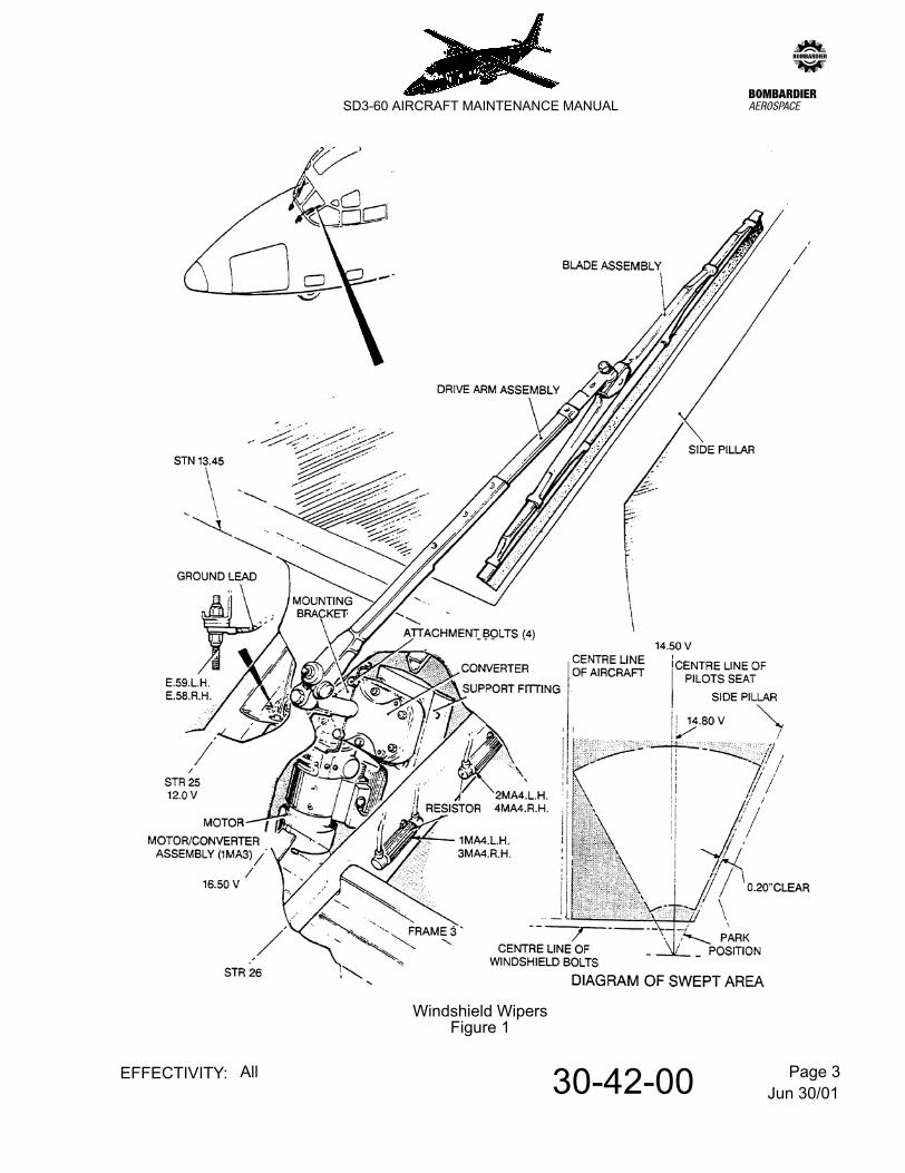
Jun 30/0130-42-00 Page 3EFFECTIVITY: All
zSD3-60 AIRCRAFT MAINTENANCE MANUAL
Windshield WipersFigure 1
Jun 30/0130-42-00 Page 201EFFECTIVITY: All
zSD3-60 AIRCRAFT MAINTENANCE MANUAL
AMM30-42-00 31.0.0.0WINDSHIELD WIPERS - MAINTENANCE PRACTICES
1. Removal/Installation
A. Remove converter
(1) Unlock and remove bolt securing the drive arm assembly to the converter shaft. Remove the drive arm assembly complete with wiper blade.
NOTE: If the same wiper and drive arm assembly is to be refitted carefully mark the arm in relation to the converter shaft.
(2) Open circuit breaker CB39 on panel 1D (left hand) or circuit breaker CB189 on panel 2D (right hand).
(3) Disconnect electrical plug from motor.
(4) Disconnect earth lead from motor at E59 (left hand) or E58 (right hand).
(5) Remove the bolts attaching the motor/converter/support fitting assembly to the structural mounting bracket (this enables the complete unit to be removed from the aircraft).
(6) Withdraw the converter from the end of the motor, taking care to retain the coupling shaft. The connector sleeve remains screwed into the end of the converter assembly and the motor remains bolted to the support fitting.
B. Install converter
(1) Examine the O-ring seal Pt No. MS9386-016, located in the support block for damage, replace as necessary.
(2) With the motor bolted to the common support fitting, slide the coupling shaft onto the squared end of the armature shaft of the motor.
(3) Examine the converter for signs of damage and slide the connector sleeve assembly attached to the converter over the housing on the end of the motor.
(4) Ensure that the squared end of the worm shaft in the converter engages the square hole in the coupling shaft. Ensure also that the O-ring, Pt No. MS9386-016, in the connector sleeve assembly is not damaged when sliding the converter assembly onto the and housing of the motor. The O-ring prevents rainwater and moisture from entering the converter area.
(5) Ensure the attachment holes in the converter line up with the holes in the support fitting and refit the complete unit to the mounting bracket in the aircraft with the appropriate bolts and nuts and secure.
(6) Re-connect the earth lead from the motor to the terminal post on stringer 25 (E59 left hand or E58 right hand).
Jun 30/0130-42-00 Page 202EFFECTIVITY: All
zSD3-60 AIRCRAFT MAINTENANCE MANUAL
(7) Re-connect electrical plug to motor and secure.
(8) Close circuit breaker CB39 on panel 1D (left hand) or circuit breaker CB189 on panel 2D (right hand).
(9) Replace drive arm assembly on splined end of converter shaft and secure with bolt, ensuring that any locating marks relating to the relationship of the converter shaft to the drive arm assembly position are re-aligned.
C. Remove wiper motor
(1) Open circuit breaker CB39 on panel 1D (left hand) or circuit breaker CB189 on panel 2D (right hand).
(2) Disconnect electrical plug from motor.
(3) Disconnect earth lead from motor at E59 (left hand) or E58 (right hand).
(4) Remove the four bolts attaching the motor to the support fitting (screwed into threaded holes in the motor casing).
NOTE: The motor attachment bolts are locked with Loctite Grade B and resistance to removal will be felt.
(5) Withdraw the motor from the connector sleeve assembly, taking care to retain the coupling shaft. The connector sleeve assembly remains screwed into the end of the converter assembly.
D. Install motor
(1) Ensure that the coupling shaft is engaged on the square end of the worm shaft of the converter assembly.
(2) Place the mounting face of the motor onto the mounting face of the support fitting and slide towards the converter until the housing on the end of the motor engages with the connector sleeve assembly and the squared end of the armature shaft of the motor engages with the square hole in the coupling shaft.
(3) Adjust the position of the motor relative to the converter until the attachment holes in the support fitting line up with the tapped holes in the motor casing.
(4) Attach the motor with the appropriate bolts suitably secured with an application of Loctite Grade B.
NOTE: Converter assembly and cam switch in motor must both be in the PARK position when installing the motor. This will ensure correct stowage of the wiper blade assembly in the PARK position. This also applies when removing and installing a converter assembly.
Jun 30/0130-42-00 Page 203EFFECTIVITY: All
zSD3-60 AIRCRAFT MAINTENANCE MANUAL
(5) Re-connect the earth lead from the motor to the terminal post on stringer 25 (E59 left hand or E58 right hand).
(6) Re-connect electrical plug to motor and secure.
(7) Close circuit breaker CB39 on panel 1D (left hand) or circuit breaker CB189 on panel 2D (right hand).
(8) Check system to see that both the wiper and motor stop in the PARK position using a wetted windshield.
2. Adjustment/Test
A. Adjust drive arm and wiper blade
(1) Prior to fitting drive arm and wiper blade operate windshield wiper and observe that converter shaft oscillates.
(2) Set WIPER switch to OFF, so that the converter shaft stops approximately at the end of its stroke in the parked position. To better observe this, wrap a short piece of locking wire around the tip of the drive shaft and leave one end projecting an inch or two as a position indicator. Several attempts may be necessary to achieve this condition.
(3) With the adjustment sleeve inserted in the drive arm in any position, place the drive arm assembly on the converter shaft as close to the parked position as possible.
NOTE: The blade assembly should be adjusted relative to the drive arm so that it lies parallel to and 0.20 inches clear of the windshield side pillar (parked position)
(4) Measure the error in the blade position (in inches) and divide by .034. The result is the approximate number of serrations that the adjustment sleeve has to be rotated in the same direction as the arm requires to be moved.
(5) Mark the position of the drive arm relative to the converter shaft and then remove the drive arm assembly.
(6) Marking the relative position of the adjustment sleeve to the drive arm, remove the sleeve and rotate it in the direction of the required adjustment the number of serrations necessary, and replace.
(7) Replace the drive arm assembly on the converter shaft, noting that it is parked parallel to the windshield and 0.20 inches clear of it. Tighten and wirelock the attachment bolt into the end of the converter shaft.

Jun 30/0130-42-00 Page 204EFFECTIVITY: All
zSD3-60 AIRCRAFT MAINTENANCE MANUAL
CAUTION: DO NOT OPERATE WINDSHIELD WIPERS OVER DRY GLASS.
DO NOT ALLOW ARM TO SLAP SIDE PILLAR.
(8) Operate windshield wiper over the windshield (wetted) for minimum period of 30 seconds, observing that it wipes over the desired area. Stop and park the wipers a few times to ensure that they stop at the PARK position each time.
B. Function test
CAUTION: WINDSHIELD WIPERS MUST NOT BE OPERATED FOR TEST PURPOSES UNLESS THE WINDSHIELD IS LUBRICATED WITH WATER.
(1) Refer to 12-09-03, pb301. Energise the Left and Right 28V DC Essential Services busbars.
(2) Close CB39 and CB189 on respective left and right distribution panels 1D and 2D.
(3) Carry out the following for the left and right wipers in turn.
(a) Set appropriate FAST/SLOW switch to FAST.
(b) Select corresponding wiper control switch ON/OFF/PARK to ON and check that associated wiper operates smoothly over the correct travel at approximately 170 cycles per minute (cpm).
(c) Select FAST/SLOW switch to SLOW and check that blade now operates at approximately 100 cpm.
(d) Momentarily select PARK, release to OFF and check that the wiper has stopped at the correct park position. Refer to 30-42-00, Figure 1.
3. Inspection/Check
A. Check wiper blade pressure
(1) Spray water on windshield and position wiper arm in the PARK position.
CAUTION: DO NOT OPERATE WINDSHIELD WIPERS ON DRY GLASS.
(2) Pressure of the wiper blade against the windshield must be 5 Ib to 8 Ib. Check this by hooking a spring balance under the arm at the wiper blade attachment point and taking a reading as the blade commences to lift from the glass. If necessary, adjust the pressure by adjusting the tension adjusting screw at the actuator arm hub.
(3) When adjusting the pressure with the adjusting nut, turn it back slightly to make sure the head of the tee-bolt is seated parallel to the groove.
(4) Operate the windshield wiper over the wetted windshield for 30 seconds and re-check the pressure. If necessary, re-adjust and re-test.
Jun 30/0130-43-00 Page 1EFFECTIVITY: All
zSD3-60 AIRCRAFT MAINTENANCE MANUAL
AMM30-43-00 32.0.0.0RAIN REPELLENT SYSTEM - DESCRIPTION & OPERATION
1. Description
A. General
This system is installed to dispense a rain repellent fluid to the aircraft windshield. It is intended for use when the aircraft is operating under conditions of medium to heavy rainfall to provide considerably clearer vision than is possible by the use of windshield wipers. The repellent fluid is stored in a pressurized canister mounted in a rack on the control duct behind the second pilots seat. From the rack the fluid is piped to two nozzles projecting through the skin sheeting, one in front of each windshield. Control of the fluid flow is by means of two independently operated solenoid valves, the outlet ports of which are connected directly to the nozzles. The solenoid valves are themselves controlled by push-button switches on the pilots panel 1P, adjustable time delay relays being included in the circuit to regulate duration of flow.
B. Canister and mounting rack
The repellent canister is pressurized by nitrogen to 85 psi. and has a fluid capacity of 500 c.c. It is carried in a rack mounted on the control duct behind the second pilots seat. When fitted to the rack, the canister is screwed into an adapter socket and secured by a strap type clamp which is tightened by a thumbscrew. Connected between the adapter socket and the pipe leading to the nozzles is a sighting glass containing a float which is normally at the top but falls when the canister empties. When the canister is screwed home its ball valve is depressed to allow the system to become pressurized under the control of the solenoid valves.
C. Solenoid-operated valves
The solenoid valves are located in the nose compartment each one immediately beneath the nozzle it controls. Their output ports are screwed directly into the nozzle assemblies and their input ports are connected by metal braided PTFE piping via a teepiece to the pipe from the mounting rack. The valves are normally closed and are only open when their coils are energized by the pilots switches under the control of the time delay relays.
D. Time delay relays
These are mounted on the structure immediately forward of panel 1P and are connected in the circuit between the pilots switches and the solenoid valves. The delay period is variable to allow the contacts to remain closed for 0.1 to 0.5 sec. depending on the setting of the adjusting screw at the top of each unit. The time delay relays are initially adjusted to allow each solenoid valve to remain open for sufficient time to dispense enough fluid to rain proof its windshield in one operating cycle.
30-43-00 Page 2EFFECTIVITY: All
zSD3-60 AIRCRAFT MAINTENANCE MANUAL
E. Power supplies
The two 28V dc supplies, one for each windshield are taken from the ESSENTIAL SERVICES busbar via circuit breakers on panel 1D and 2D. The left windshield is supplied via circuit breaker No.246 on panel 2D from the RIGHT ESSENTIAL SERVICES busbar, and the right windshield via circuit breaker No.46 on panel 1D from the LEFT ESSENTIAL SERVICES busbar. This arrangement is the opposite to that of the windshield wipers and ensures that if a busbar fails then each windshield has either repellent or windshield wiper.
2. Operation
A. General
The system will only function satisfactorily when, under conditions of medium to heavy rainfall, the rain is seen to be streaming up the windshield. Under these conditions the repellent fluid will spread over the screen to provide clear vision without the use of the windshield wipers. It may however, be necessary to use the wipers for downwind taxiing. To operate the system it is only necessary to press the push-button switches, in turn, leaving a sufficient interval to allow the first screen to clear before pressing the second switch. One application of the repellent should be sufficient to cover a complete take-off or landing sequence under heavy rain conditions.
B. Operating procedure
WARNING: REPELLENT MUST ONLY BE APPLIED WHEN RAIN IS SEEN TO BE STREAMING UP THE SCREEN. DO NOT FUNCTION THE SYSTEM AS A PRE-FLIGHT CHECK.
(1) Check that sight glass float is at the top of the glass indicating availability of fluid.
(2) Press left switch for left windshield or right switch for right windshield, as required.
WARNING: APPLY REPELLENT TO ONE SCREEN ONLY AND ALLOW REPELLENCY TO BECOME ESTABLISHED BEFORE PRESSING SECOND SWITCH TO APPLY REPELLENT TO OTHER SCREEN.
(3) Repeat (refresher) applications may be made at intervals when vision begins to worsen again due to deterioration of the previous repellent application.
NOTE: (1) Vision may be temporarily impaired by foaming on the lower part of the screen, this will persist for a few seconds only.
(2) One application of repellent fluid per windshield is normally sufficient to cover a complete take-off or landing sequence in heavy rain conditions.
(3) The fluid does not have screen washing qualities; effective action will not take place if the screen surface is dry or only slightly wet. Visibility may be distorted by dried repellent under these conditions and will be further impaired by smearing if the wipers are used in an attempt to clear the screen.
Jan 29/10
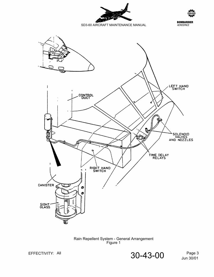
Jun 30/0130-43-00 Page 3EFFECTIVITY: All
zSD3-60 AIRCRAFT MAINTENANCE MANUAL
Rain Repellent System - General ArrangementFigure 1
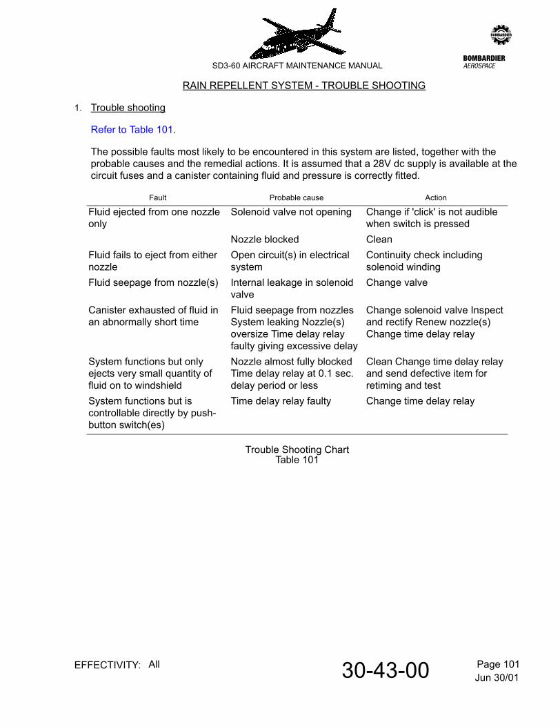
Jun 30/0130-43-00 Page 101EFFECTIVITY: All
zSD3-60 AIRCRAFT MAINTENANCE MANUAL
AMM30-43-00 33.0.0.0RAIN REPELLENT SYSTEM - TROUBLE SHOOTING
1. Trouble shooting
Refer to Table 101.
The possible faults most likely to be encountered in this system are listed, together with the probable causes and the remedial actions. It is assumed that a 28V dc supply is available at the circuit fuses and a canister containing fluid and pressure is correctly fitted.
Trouble Shooting ChartTable 101
Fault Probable cause Action
Fluid ejected from one nozzle only
Solenoid valve not opening Change if 'click' is not audible when switch is pressed
Nozzle blocked CleanFluid fails to eject from either nozzle
Open circuit(s) in electrical system
Continuity check including solenoid winding
Fluid seepage from nozzle(s) Internal leakage in solenoid valve
Change valve
Canister exhausted of fluid in an abnormally short time
Fluid seepage from nozzles System leaking Nozzle(s) oversize Time delay relay faulty giving excessive delay
Change solenoid valve Inspect and rectify Renew nozzle(s) Change time delay relay
System functions but only ejects very small quantity of fluid on to windshield
Nozzle almost fully blocked Time delay relay at 0.1 sec. delay period or less
Clean Change time delay relay and send defective item for retiming and test
System functions but is controllable directly by push-button switch(es)
Time delay relay faulty Change time delay relay
Jun 30/0130-43-00 Page 102EFFECTIVITY: All
zSD3-60 AIRCRAFT MAINTENANCE MANUAL
THIS PAGE LEFT BLANK INTENTIONALLY
Jun 30/0130-43-00 Page 201EFFECTIVITY: All
zSD3-60 AIRCRAFT MAINTENANCE MANUAL
AMM30-43-00 34.0.0.0RAIN REPELLENT SYSTEM - MAINTENANCE PRACTICES
1. General
When servicing this equipment it is essential to prevent the ingress of dirt, swarf or water. As the fluid is of a highly hygroscopic nature the presence of even small quantities of water can cause gelling of the fluid and the formation of gritty deposits in the system. These, like the dirt or swarf, can prevent the solenoid valves from seating properly thereby allowing seepage of the fluid from the nozzles. If, when changing a component in the system, it is necessary to leave a pipe connection open a blanking piece must be fitted. Water or undried gas must never be used to test the system for any purpose whatsoever.
CAUTION: THE REPELLENT FLUID CONTAINS VOLATILE SOLVENTS. AVOID PROLONGED BREATHING OF THE VAPOUR, PROLONGED CONTACT WITH THE SKIN AND DO NOT TAKE INTERNALLY. IF THE FLUID ACCIDENTALLY COMES INTO CONTACT WITH THE EYES BATHE IMMEDIATELY WITH CLEAN WATER.
IT IS IMPORTANT TO NOTE THAT THE REPELLENT FLUID CONTAINS SILICONES. IT WILL THEREFORE BE NECESSARY TO FOLLOW AN APPROVED PROCEDURE FOR SILICONE REMOVAL BEFORE REPAINTING THE SKIN OR STRUCTURE IN THE VICINITY OF THE WINDSHIELD.
2. Replace a canister
To remove a canister the thumbscrew on the securing strap is first slackened to allow the canister to be unscrewed from its adapter socket. An empty canister should not be removed unless a replacement is immediately available. Indication that a canister is empty is given by the position of the float in the sighting glass. It is advisable to ensure that the system is never permitted to dry out, either by leaving the canister off or allowing the fluid level to fall too low, as gummy deposits may be formed which could be difficult to remove. The contents of a canister may be determined approximately by comparing its weight with that of a new one. For fluid consumption calculation purposes it may be assumed that one application will use 5 c.c. per puzzle and a single application will last 5-10 minutes in heavy rain and up to 40 minutes in moderate rain.
3. Clean a nozzle
The nozzles must be examined at frequent intervals to ensure that they are free from dirt and repellent residue. Clogged nozzles may be cleared with a probe made from soft copper wire to avoid damaging the orifice. Dried fluid may be softened with Stoddards solvent, white spirit or Aliphatic naptha. If it is required to test a nozzle by discharging fluid through it there must be plenty of water readily available, both to wet the screen thoroughly before the test and to wash away the fluid after. If, due to an inadvertant operation of the system with the windshield dry, fluid has hardened on the screen it may be softened to some extent by the application of fresh repellent on a tissue. To remove it completely from the screen it may have to be polished off, using an approved windshield polishing fluid.
30-43-00 Page 202EFFECTIVITY: All
zSD3-60 AIRCRAFT MAINTENANCE MANUAL
4. Remove a solenoid valve
Before removing a faulty solenoid valve the electrical circuit should be rendered 'dead' by opening the appropriate circuit breaker and the pressure should be removed from the system by unscrewing the canister from its adapter socket. The valve is then removed by withdrawing the electrical socket, unscrewing the 'inlet' pipe connector and disconnecting the outlet port from the nozzle assembly.
5. Adjust a time delay relay
As the time delay relays are not set to any particular time delay period by the manufacturer it will be necessary to set a replacement relay to operate at the period determined by flight tests on the aircraft. The adjustment (from 0.1 to 0.5 sec.) is made by slackening the locknut on the adjuster screw and turning the screw clockwise to increase, and anti-clockwise decrease, the delay period. The delay period recommdned by the manufacturers of the system is, for this aircraft, 0.35 - 0.45 secs. A setting of 0.4 secs may be obtained by the following procedure:-
A. Turn adjuster screw to the limits of its travel in both directions, making a pencil mark on the relay in alignment with the red line on the adjuster at each end of the limit of travel.
B. Estimate and mark the mid-point between the previously made extreme marks. Align the red line of the adjuster screw with the centre pencil mark. The relay will now be timed to a delay of 0.3 sec. (+.000 - .030). Further division of the area of movement on either side of the mid-point into three equal spaces will provide four further points which may be used to provide two additional setting points. The points adjacent to the mid-point may be taken as:- 0.2 sec. to the left and 0.4 sec. to the right.
NOTE: The points adjacent to the extremes of travel should not be used owing to possible inaccuracies caused by the actual delay range being slightly in excess of the design requirement.
6. Function test the system
Before carrying out a function test on the installation all components should be inspected for cleanliness, evidence of damage, fluid leakage and security of attachment. All flexible pipes should be examined for damage, kinking, security and evidence of leaks. Electrical cables should be examined for security, signs of deterioration of insulation and for damage, corrosion and security of plugs and sockets. The function test is then carried out after first removing the canister, using the following procedure:-
A. Check that the 28V dc supply is switched on.
B. Ensure that circuit breaker No.46 and No.246 in fuse panel 1D and 2D respectively are closed.
Jan 29/10
30-43-00 Page 203EFFECTIVITY: All
zSD3-60 AIRCRAFT MAINTENANCE MANUAL
C. Operate a push-button switch, at the same time listening for a simultaneous click from the associated solenoid valve, indicating that it has opened. A second click from the solenoid valve should immediately follow the first, indicating that the valve has closed and that the time delay relay has operated correctly.
D. Repeat C for the other switch.
E. If C and D are satisfactory the canister may be fitted.
F. When the canister is fitted check that the sighting gauge operates; the float should be at the top of the glass.
G. Position an assistant with a container of clean water and a sponge adjacent to the windshield.
NOTE: Alternatively the assistant can hold a piece of soft absorbent cloth or tissue close to each nozzle to collect the discharge.
H. Press either switch and note that repellent fluid is ejected from the appropriate nozzle. The assistant should immediately flood the screen with clean water using the sponge.
I. Repeat H for the other switch.
NOTE: If a new solenoid valve or a new piece of piping has been fitted it may be necessary to repeat step H. or I. until the fluid appears.
Jan 29/10
Jun 30/0130-61-00 Page 1EFFECTIVITY: All
zSD3-60 AIRCRAFT MAINTENANCE MANUAL
AMM30-61-00 35.0.0.0PROPELLER ANTI-ICING (FIVE-BLADED PROPELLERS) - DESCRIPTION & OPERATION
NOTE: Six-bladed propeller anti-icing (aircraft equipped with PT6A-67R engines). Refer to 30-62-00, pb1.
1. Description
A. General
Refer to Figure 1.
This installation is a B.F. Goodrich 'HotProp' 2-cycle de-icing system and comprises a lightweight heater mat bonded to each propeller blade forming two groups of five and two cyclic timers respectively controlling the heater group/frequency for left and right propeller de-icing. Each timer is connected to the propeller heating mats via brush blocks and a slip ring assembly.
The 'HotProp' designed heater mat incorporates an etched heating element which is distributed throughout the mat so that heat is intensified at the 'root' of the blade (where ice build-up is heaviest) with diminishing heat transmission along the stem. When heat is applied the ice bond is broken, dispersing the ice by centrifugal force and scavenging airstream.
B. Timer
The transistorised timers are each mounted with their associated relays and contactors on panels 5C and 6C for left and right propellers, respectively. When a 28V d.c. supply is connected to input terminal 'B' the timer will function, providing a supply via terminal 'D' to the transfer relay and thence to the propeller heaters. The timer cycle (180 seconds) will transmit power to the heaters for 90 seconds followed by an 'off' period for 90 seconds, repeating. Terminal 'F' on each timer is interconnected to the opposite transfer relay, providing an auxillary supply should its timer fail, the control switch on the failed side being set to TFR (transfer).
Control of the timers is by two ON/OFF/TFR switches on de-icing panel 4P. When a control switch is selected ON the contactor relay is energised, providing power to the input terminal of the timer. If the control switch is set to TFR (transfer) as a result of a faulty timer, propeller heat on the defective side, will be monitored by the opposite timer.
C. Brush blocks and slip ring assembly
The electrical connections to the propeller heaters are made via the brush blocks and a propeller-mounted slip ring assembly. The slip ring consists of two concentric copper rings embedded in insulating material on an aluminium plate. The inner ring is the earth conductor and the outer, the supply.
Jun 30/0130-61-00 Page 2EFFECTIVITY: All
zSD3-60 AIRCRAFT MAINTENANCE MANUAL
D. Indication
Cycle indication of current flow to the propeller heaters is provided via current sensing relays in each heating circuit signalling the ON caption situated above each control switch (panel 4P).
2. Operation
With the appropriate power supplies made available for left and right operation and the control switches selected ON, power will be transmitted through the respective contactor relay, current sensing relay, timer, transfer relay and brush block assembly to the five heater elements of each propeller. The timer will continue to cycle heat to the propeller i.e. 90 seconds - on / 90 seconds - off until switched OFF.
Indication of current flow through the current sensing relays is displayed by the illumination of ON indicators producing a corresponding time signal for the heat cycle duration.
In the event of a cycle indication failure the appropriate control switch on the failed side is set to TFR (transfer) thereby connecting its heaters to the opposite timer. Subsequent to this contingency the ON indicator for the operational timer will be illuminated continuously signifying control of the heaters on both propellers. If the ON indicator does not remain illuminated, it is indicative of heater element/brush assembly failure on the defective side.
3. Power supplies
The 28V d.c. supplies for the control circuits are respectively taken from the left and right shedding busbars via 5 amp. circuit breakers No.8 and 158 on distribution panels 1D and 2D. The 28V d.c. heater supplies are respectively taken from the left and right main busbars via 35 amp. circuit breakers Nos. 7 and 157 on distribution panels 1D and 2D. When a control switch is set to TFR (transfer) the heaters of both propellers are supplied from the same busbar.
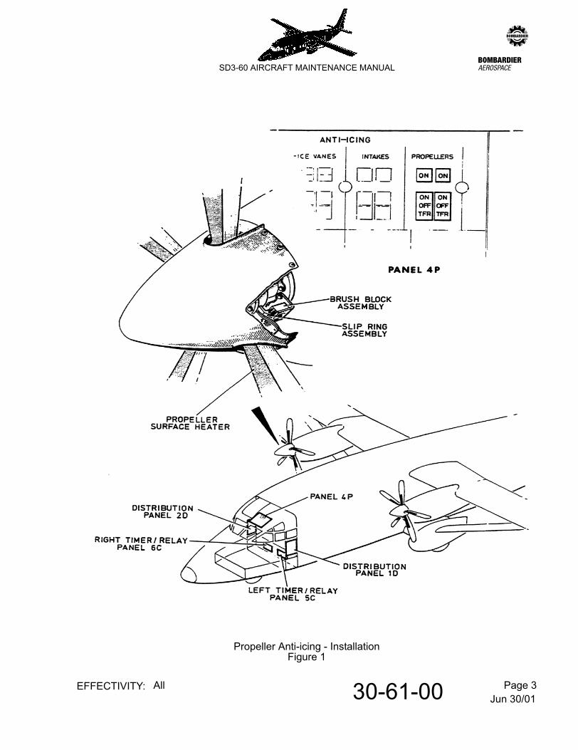
Jun 30/0130-61-00 Page 3EFFECTIVITY: All
zSD3-60 AIRCRAFT MAINTENANCE MANUAL
Propeller Anti-icing - InstallationFigure 1
Apr 24/0330-61-00 Page 201EFFECTIVITY: All
zSD3-60 AIRCRAFT MAINTENANCE MANUAL
AMM30-61-00 36.0.0.0PROPELLER ANTI-ICING (FIVE-BLADED PROPELLERS) - MAINTENANCE PRACTICES
NOTE: Six-bladed propeller anti-icing (aircraft equipped with PT6A-67R engines). Refer to 30-62-00, pb201.
1. Adjustment/Test
A. Function check
(1) Remove spinners from both propellers.
(2) Remove connectors at brush block assemblies 'HA8' on left engine.
(3) Connect an Avometer across brush block assembly connector pins B and C and check that resistance measures 1.7 to 1.9 ohms.
(4) Repeat paras (2) and (3) for right engine.
(5) Energise Main and Shedding 28V d.c. busbars from a ground supply.
(6) Connect 28 volt test lamp as follows:-
- Lamp A - across pins B and C on left socket.- Lamp B - across pins B and C on right socket.
(7) Ensure that left PROP HEAT and PROP HEAT CONTROL circuit breakers Nos.7 and 8 on panel 1D are closed.
(8) Select left PROPELLERS switch on panel 4P ON and check that test lamp operates in the sequence A-90 sec on..., A-90 sec off....A-90 sec on repeating.
NOTE: During this test the left propeller indicator remains black.
(9) Ensure that cycling stops when the PROPELLERS switch is selected OFF and/or circuit breakers Nos. 7 & 8 (panel 1D) are tripped.
(10) Ensure that right PROP HEAT and PROP HEAT CONTROL circuit breakers Nos. 157 and 158 on panel 2D are closed.
(11) Select right PROPELLERS switch on panel 4P ON and check that test lamp operates in the sequence B-90 sec on ... B-90 sec off ... B-90 sec on repeating.
NOTE: During this test the right propeller indicator remains black.
(12) Ensure that cycling stops when the PROPELLERS switch is selected OFF and/or circuit breakers Nos. 157 and 158 (panel 2D) are tripped.
Equipment required: Avometer
Apr 24/0330-61-00 Page 202EFFECTIVITY: All
zSD3-60 AIRCRAFT MAINTENANCE MANUAL
(13) Ensure that PROP HEAT and PROP HEAT CONTROL circuit breakers 7 & 8 and 157 and 158 on panels 1D and 2D are closed.
(14) Select PROPELLERS heat switches - left to ON and right to TFR.
(15) Check that test lamps operate in the following sequence:-
- A-90 secs ON .......... B-90 secs ON .......... A-90 secs ON- B-90 secs ON repeating.- Ensure that left indicator remains black.
(16) Select PROPELLERS heat switches - right to ON and left to TFR.
(17) Check that the test lamps operate in the following sequence:-
- A-90 secs ON .......... B-90 secs ON .......... A-90 secs ON- B-90 secs ON repeating.- Ensure that the right indicator remains black.
(18) Select both PROPELLERS heat switches OFF.
(19) Disconnect test lamps and re-connect brush block assemblies.
(20) Select both PROPELLERS heat switches ON and check for one cycle only that:-
(a) all five heater mats on each propeller are heating
(b) both ON indicators (green) on panel 4P illuminate during heat transmission
(c) both VANE L and VANE R segments (amber) of the annunciator on the Central Warning Panel (CWP) are illuminated.
NOTE: select both ANTI-ICE VANES switches on panel 4P to ON, then OFF and check that the complete annunciator on the CWP extinguishes and illuminates again.
(21) Select both PROPELLERS heat switches OFF.
NOTE: Check that all indications are extinguished.
(22) Disconnect two heater mats at each propeller.
(23) Select both PROPELLERS heat switches ON and check that both indicators on panel 4P remain black. Select switches OFF.
(24) Re-connect heater mats.
(25) Repeat para (20).
(26) Replace propeller spinners.
Jun 30/0130-61-01 Page 201EFFECTIVITY: All
zSD3-60 AIRCRAFT MAINTENANCE MANUAL
AMM30-61-01 37.0.0.0BRUSH BLOCK (FIVE-BLADED PROPELLERS) - MAINTENANCE PRACTICES
NOTE: Six-bladed propeller anti-icing (aircraft equipped with PT6A-67R engines). Refer to 30-62-01, pb201.
1. Removal/Installation
A. Remove a brush block.
(1) Open circuit breakers Nos 7 and 8 on left distribution panel 1D and circuit breakers Nos 157 and 158 on right distribution panel 2D.
(2) Gain access to the brush block assembly by lowering the intake cowl.
(3) Disconnect two electrical cables.
(4) Remove both attachment screws and the brush block from the mounting plate.
B. Install a brush block.
(1) Ensure that circuit breakers Nos 7 and 8 on left distribution panel and circuit breakers Nos 157 and 158 on right distribution panel are open.
(2) Locate the brush block on the mounting bracket, taking care not to exert any side load on the brushes which may cause breakage. Install the attachment screws, washers and nuts (do not fully tighten).
(3) Adjust brush alignment as follows to achieve a quiet, efficient transfer of electrical power to the slip rings.
(a) Brush track alignment
Align the brush block assembly using shim material if necessary, so that the entire face of each brush is in contact with the copper slip ring throughout the full 360° rotation.
(b) Brush projection
Refer to Figure 201.
Position the brush holders to achieve a clearance to the slip ring of 1/16 in ± 1/32 in with an angular displacement of 2° relative to the centre line of the propeller and the direction of rotation. Tighten the brush block securing screws.
(4) Reconnect the electrical cables to the terminals on the brush block assembly.
(5) Close circuit breakers Nos. 7 and 8 on the left distribution panel 1D and circuit breakers Nos 157 and 158 on the right distribution panel 2D.

Jun 30/0130-61-01 Page 202EFFECTIVITY: All
zSD3-60 AIRCRAFT MAINTENANCE MANUAL
Brush ProjectionFigure 201
Jun 30/0130-61-01 Page 203EFFECTIVITY: All
zSD3-60 AIRCRAFT MAINTENANCE MANUAL
2. Cleaning/Painting
WARNING: DAMAGE TO THE PROPELLER ANTI-ICING SYSTEM CAN OCCUR IF GREASE OR OIL/CARBON DUST DEPOSITS ARE ALLOWED TO FORM ON THE BRUSH BLOCK AND ASSOCIATED SLIP RINGS.
A. Clean the brush block and slip rings.
Perform the following at each engine in turn:-
(1) Remove the brush block (refer to para 1. A)
(2) Clean the assembly with a cloth dampened with MEK (methyl-ethyl-keytone).
CAUTION: DO NOT SOAK BRUSH ASSEMBLY IN SOLVENT.
(3) Clean greasy or contaminated slip rings with CRC 2-26 solvent (CRC Chemicals, Dresher, Pa. USA) or with Stoddart solvent.
NOTE: If Stoddart solvent is used, wipe off with a clean cloth dampened with MEK to avoid leaving a film.
(4) Refit brush block assembly as detailed in para 1.B.
Jun 30/0130-62-00 Page 1EFFECTIVITY: All
zSD3-60 AIRCRAFT MAINTENANCE MANUAL
AMM30-62-00 38.0.0.0PROPELLER ANTI-ICING (SIX-BLADED PROPELLERS) - DESCRIPTION & OPERATION
NOTE: Five-bladed propeller anti-icing (aircraft equipped with PT6A-65R or -65AR engines). Refer to 30-61-00, pb1.
1. Description
A. General
The propellers are each electrically de-iced in two alternate blade group sequences by B.F. Goodrich 2-cycle de-icing system. When heat is applied to a blade, the ice bond is broken and ice is dispersed by centrifugal force and by the scavenging airstream.
The installation comprises two timer-controlled left and right sub-systems. The electrical arrangement permits both propellers to be de-iced from the one timer if the opposite timer fails. System control also enables selection of one or other of two modes of operation; this varies the heating cycle 'on-time' to suit the severity of the icing conditions encountered.
The heater elements are embedded within each blade and extend from the blade root to radius station 30.5 in. Timer output power is connected to the heaters by brush blocks and a slipring assembly.
All control switches and indicators for the system are on the ANTI-ICING section of overhead panel 4P.
The system is operationally inhibited with the engines stopped; or, if the ambient temperature is above 30°C with the engines running, however the controls include two test switches which enable 'fast-stepping' of the associated timers through their cycle sequences without running the engines.
On aircraft Prod Serial No. SH3743 and subsequent aircraft and those aircraft post mod A8455, if it should become necessary to shut down an engine in a situation where only that system timer is operative, the opposite propeller may still be heated from the shut down engine's timer circuit.
B. Equipment Panels
(1) Panel 41C and 42C:
These are respectively located in the rear of the left and right engine nacelle monocoque. The following propeller de-icing equipment is mounted on each panel:-
Panel 41C Panel 42C
Component Circuit Ident Circuit Ident
Electronic Timer N P60A Circuit Breaker A LIndication Relay ('on-time') K M

Jun 30/0130-62-00 Page 2EFFECTIVITY: All
zSD3-60 AIRCRAFT MAINTENANCE MANUAL
(2) Panel 29C and 30C:
The panels are respectively positioned on the left and right rear face of the step at fuselage frame station 74. The propeller de-icing associated equipment located on each panel comprises:-
C. Timers
The electronic timers, one each on equipment panels 41C and 42C have the following input and output functions:-
Contractors (4) B FC GD HE J
Panel 29C Panel 30C
Component Circuit Ident Circuit Ident
Indication Relay ('on-time') K MOil Pressure Relay J LMode indication relay - N
Pin Function
S Receives 28V dc input from the timer associated main busbar thru the 60A circuit breaker.
B (a) Activates timer in 20 sec. mode when; timer associated 28V dc shedding busbar is live, mode switch is set to BELOW -10, timer switch is at ON and engine is running (oil pressure relay de-energized).(b) Activates timer in the 'fast stepping' checking sequence in the 20 sec. mode when: engine is stopped, mode switch is set to BELOW -10, timer switch is at ON and the associated PRESS-TO-TEST switch/indicator is pushed repeatedly to step advance the timer through the mode sequence (as confirmed by the illuminating sequence of the indicators upper and lower ON captions).
C (a) Activates timer in 10 sec. mode when; timer associated 28V dc shedding busbar is live, mode switch is set to NORM, timer switch is at ON and engine is running (oil pressure relay de-energized).
Panel 41C Panel 42C
Component Circuit Ident Circuit Ident
Jun 30/0130-62-00 Page 3EFFECTIVITY: All
zSD3-60 AIRCRAFT MAINTENANCE MANUAL
D. Heater Contactors
Heater contactors B&C on panel 41C (left) and H&J on panel 42C (right) are energized (a) when both timer control switches are selected ON with the engines running. (b) intermittently during test with engines stopped (for the short periods the associated timers test switch/indicator is pushed during the advance step cycle test). The supply to the coils of the referred contactors is taken from the 28V dc shedding busbars (via series connected contacts on the normally de-energized contactors D&E on panel 41C and F&G on panel 42C).
Contactors D&E and F&G only energize as a pair if the timer on the associated side is selected to TFR (transfer); this avails (a) the 'dwell' outputs from pins H&J on the functional timer to the propeller blade heaters on the failed side and (b) de-energizes the normal contactors on that side to isolate the faulty timer from its related propeller.
E. Thermostats
On all aircraft post mod A8299 (production Ser. Nos SH 3721 and up), and on those prior Ser. Nos. on which Service Bulletin SD360-30-15 is incorporated, two thermostats, circuit-idented 1HA17 (left) and 2HA17 (right) are located left of the aircraft centre line at STN 117 under the fuselage top fairing.
(b) Activates timer in the 'fast stepping' checking sequence in the 10 sec. mode when; engine is stopped, mode switch is set to NORM, timer switch is at ON and the associated PRESS-TO-TEST switch/indicator is pushed repeatedly to step advance the timer through the mode sequence.
D 28V dc input from timer associated shedding busbar to energize the appropriate indication relay (panel 29C or 30C) when the current sensor within the timer connects pin D to ground pin A on sensing a heater current draw from any of output pins E, F, H and J.
A See pin D.E&F Normal timer sequenced outputs via contactors (para D) to
associated propeller for alternate blade sequenced heating cycles. A pin E output also energizes the timer related indication relay (panel 41C or 42C) to illuminate the lower ON caption of the timer test switch/indicator. The upper ON caption illuminates when pin F outputs.
H&J Normal dwell phases. Provides 28V dc outputs via contactors (para D), to opposite propeller heaters in the event that opposite timer control switch is set to TFR. A pin H also energizes the timer related indication relay (panel 41C or 42C) to illuminate the lower ON caption of the timers test switch/indicator. The upper ON caption illuminates when pin J outputs.
Pin Function
Jun 30/0130-62-00 Page 4EFFECTIVITY: All
zSD3-60 AIRCRAFT MAINTENANCE MANUAL
If the ambient temperature rises above 30°C, the thermostat contacts make, so energizing the associated LOW FUEL and OIL PRESSURE WARNING relay, and breaking the supply to the propeller heaters.
F. Brush Block and Sliprings
The electrical connections to the heaters of each propeller are made by two brush blocks and a propeller mounted slipring assembly. The slipring consists of three concentric copper rings inbedded in insulating material on the rear of the spinner bulkhead. The inner ring is the ground conductor; the centre and outer rings are the supply to each of the two groups of three alternate blade heaters.
G. Controls and Indication
The following propeller de-icing controls and indicators are presented on the ANTI-ICING section of overhead panel 4P in the flight compartment:-
(1) Timer control switches
These are 3-position rocker-type switches, ON-centre OFF-TFR; one for left and one for right timer control.
(2) Mode Switch
This 2-position switch, NORM/ BELOW-10 permits choice of heating cycle 'on-time' to suit the severity of the icing conditions encountered. NORM operationally selects heat phase periods of 10 seconds; BELOW -10 sets 'on-time' to 20 seconds.
(3) Mode Indicator
This is a '2-windowed' electrical indicator located above the mode switch. The upper and lower windows are respectively captioned NORM and BELOW-10; one or other of the captions is operationally illuminated to confirm the mode selected.
Setting Function
ON To operate associated timer in the cycle determined by the mode switch setting, provided the engine is running (oil pressure relay de-energized). With engine stopped, this setting permits 'fast-stepping' of the timer as a cycle sequence check (in association with operation of the relevant test switch).
OFF Timer off.TFR To operationally permit de-icing of a running
engines propeller from the opposite timer.
Jun 30/0130-62-00 Page 5EFFECTIVITY: All
zSD3-60 AIRCRAFT MAINTENANCE MANUAL
(4) Test switch/cycle indicators
The PUSH-TO-TEST/cycle indicator is positioned above each timer switch.
The switch action is momentary press and enables the associated timer to be 'fast-stepped' through its cycling sequence when; the engine is stopped and the timer is selected ON. The integral indicator confirms the test cycle as well as providing a cycle monitoring facility during operational use of the system.
The indicator comprises upper and lower windows, both of which are captioned ON. These normally light and extinguish in consecutive sequence to confirm the two heating phases to the related propeller and remain unlit for the dwell periods determined by the mode switch setting. When an opposite timer is set to TFR, the indicator displays ON lower, ON upper, ON lower, ON upper followed by an off display (if mode switch is set to NORM).
NOTE: When the timer is initially switched ON, either for normal operation, or for test with engine stopped, the timer will commence operating at the last selected OFF output. However, fast-stepping during test is assured provided the test switch release-to-off periods do not exceed 5 seconds.
H. Power Supplies
(1) Heater Supply
NOTE: Heater power is derived from the 28V dc main busbars via the 60A circuit breakers, one each on equipment panels 41C and 42C. Control of the remote breakers is by means of C/B Nos 7 and 157 (0.5A) on respective distribution panels 1D and 2D.
(2) System Control and Indication
NOTE: Control and indication power is taken from the 28V dc shedding busbars, left and right via respective C/B Nos 8 and 158 (5A) on panels 1D and 2D.
2. Operation
A. General
A summary of system operation follows in sub-para. B thru D; detailed aspects of control circuit functions have been provided under Para. 1.
Jun 30/0130-62-00 Page 6EFFECTIVITY: All
zSD3-60 AIRCRAFT MAINTENANCE MANUAL
B. Operation - both timers functional
With engines running (related oil pressure relays de-energized) selection of both timer switches on panel 4P to ON will activate the timers in the 10 seconds or 20 second heating phase sequence as respectively determined by the NORM or BELOW-10 setting of the mode switch. Visual confirmation of the mode selected is by appropriate illumination of the mode indicator.
NOTE: Timer outputs to the related propeller will commence at the stage at which the timers were last switched OFF.
Correct cycling is confirmed by the display state of the timer-related test switch/indicators on the control panel. In the NORM mode the indicators will illuminate for 10 second intervals as follows: ON lower, ON upper followed by a both out period of 60 seconds, repeating. For a BELOW-10 mode, the cycle indicators will illuminate for 20 second intervals thus: ON lower, ON upper followed by a both out period of 40 seconds, repeating.
On aircraft production Serial No. SH3743 and subsequent aircraft and those aircraft post mod A8455, should only one engine be running with the associated anti-icing system being operated, the opposite system is inhibited in the advent of inadvertently selecting its timer switch to TFR.
C. Operation following a timer failure
If occurring, a timer failure is detected during periodic visual monitoring of the cycle indicators i.e. both segments of the related indicator are observed to either remain out well in excess of the dwell period for the operating mode (60 sec. NORM, 40 sec. BELOW-10) or, one of the segments remains illuminated continuously. In either event, the failed timer switch is operationally selected to TFR. This isolates the faulty timer from its propeller by changing over the energized state of its two pair of heater contactors, and in so doing, connects the 'dwell' outputs from the functional timer to regain de-icing of both propellers.
In the NORM mode, the active timer will illuminate its cycle indicator in 10 second intervals as follows: ON lower, ON upper, ON lower, ON upper followed by a both out period of 40 seconds, repeating. For a BELOW-10 mode, the indicator will continuously alternate illumination of the lower and upper ON captions for periods of 20 seconds.
D. Test Operation-engines stopped
With the 28V dc main and shedding busbars energized and engines stopped, the system inhibiting action of the oil pressure relays can be bypassed by means of the PUSH-TO-TEST switch/indicators on panel 4P; this enables the timers to be 'fast-stepped; throughout their cycling sequence for test purposes.
NOTE: As is the case for normal operation (engines running), timer outputs to the propellers will commence at the stage at which the timers were last switched OFF.
Jun 30/0130-62-00 Page 7EFFECTIVITY: All
zSD3-60 AIRCRAFT MAINTENANCE MANUAL
To confirm that timer logic, heaters and control circuitry are serviceable, the mode switch is set to NORM, one timer switch to ON and the opposite to TFR. The PUSH-TO-TEST switch/indicator for the ON timer is then sequence pressed (for approx. 3 seconds) and released (for not more than 5 seconds, otherwise stepping action will be lost) until the following illuminating displays on the functioning timers switch/indicator are achieved; ON lower, ON upper, ON lower, ON upper followed by one no indication press before ON lower (new cycle resumes); release switch.
The mode switch is then set to BELOW-10 and the test repeated, the exception being that the referred 'no indication' press of the test switch does not occur for this mode.
The two tests are then repeated with the timer switch settings changed over i.e. that on TFR to ON and that at ON to TFR.
Apr 24/0330-62-00 Page 201EFFECTIVITY: All
zSD3-60 AIRCRAFT MAINTENANCE MANUAL
AMM30-62-00 39.0.0.0PROPELLER ANTI-ICING (SIX-BLADED PROPELLERS) - MAINTENANCE PRACTICES
NOTE: Five-bladed propeller anti-icing (aircraft equipped with PT6A-65R or -65AR engines). Refer to 30-61-00, pb201.
1. Adjustment/Test
A. Check heater mat group resistances,
(1) Remove spinners from both propellers.
(2) Remove connectors 1HA8 and 2HA8 at brush block assemblies on left propeller.
(3) Connect an Avometer across brush block assembly connector pins A and B and then A and C. Check that each reading is 0.49 to 0.55 ohms.
(4) Repeat paras (2) and (3) for right propeller.
(5) Reconnect brush block assemblies.
B. Operational check (engines stopped)
(1) Refer to 12-09-03, pb301. Provide external electrical power and energize the 28V dc main and shedding busbars.
(2) Ensure the following C/B's are closed:-
Nos 7 & 8 (panel 1D) and Nos 157 & 158 (panel 2D).
CAUTION: TO AVOID OVERHEATING OF PROPELLER BLADES DURING STEPS (3) AND (4) WHICH FOLLOW, ENSURE THAT THE REFERRED TEST SWITCH/INDICATOR IS NOT PUSHED IN FOR PERIODS IN EXCESS OF 3 SECONDS.
NOTE: The 'release-to-off' periods for the test switch during check must not exceed 5 seconds otherwise the associated timer will not 'step advance' to the next stage. The first press will activate the timer at that stage in its cycle it was last switched OFF.
(3) Confirm left timer and associated control and output circuitry is functional as follows:
(a) On panel 4P, set mode switch to NORM, left timer to ON and right timer to TFR.
(b) Check that the VANE L annunciator on the Central Warning Panel is illuminated.
NOTE: Select the left ANTI-ICE VANES switch to ON, then OFF and check that the VANE L annunciator respectively extinguishes and illuminates again.
Equipment required: Avometer
Apr 24/0330-62-00 Page 202EFFECTIVITY: All
zSD3-60 AIRCRAFT MAINTENANCE MANUAL
(c) Sequence press and release the left PUSH-TO-TEST switch/indicator as necessary and check that the indicator displays: ON lower, ON upper, ON lower, ON upper (followed by one 'no indication' press before ON lower (new cycle) resumes; release switch.
(d) Set mode switch to BELOW-10 and repeat (b) checking that the referred 'no indication' press of the test switch does not occur for this mode.
(4) Confirm right timer and associated control and output circuitry by repeating (3), reading right for left and left for right.
(5) Ensure that circuit breaker Nos. 16 (panel 1D) and 166 (panel 2D) are open.
(6) Apply even heat to the thermostats, idented 1HA17 ands 2HA17 and located at STN 117 under the fuselage top fairing, with a heat gun until a temperature of 30°C is achieved.
(7) Select both PROPELLER heat switches to ON.
(8) Ensure that the appropriate indicators on panel 4P do NOT illuminate.
(9) Select both PROPELLER switches to OFF.
(10) Remove electrical power if no longer required.
Jun 30/0130-62-01 Page 201EFFECTIVITY: All
zSD3-60 AIRCRAFT MAINTENANCE MANUAL
AMM30-62-01 40.0.0.0BRUSH BLOCKS (SIX-BLADED PROPELLERS) - MAINTENANCE PRACTICES
1. Removal/Installation
A. Remove a brush block module.
(1) Open C/B Nos 7&8 on panel 1D and 157&158 on panel 2D.
(2) Refer to 6-30-00, pb1. Gain access to the brush block assemblies by lowering the intake cowl and removing panel 420AB.
NOTE: The blocks are bracket-mounted on the propellers reduction gearcase front cover; the left unit is circuit-idented 1HA8, the right is 2HA8.
(3) To remove a brush block, proceed as follows:-
(a) Disconnect the three electrical cables from the module.
(b) Remove the two sets of attachment screws, washers and nuts which secure the unit to its mounting bracket. Retain packing material released with the block.
B. Install a brush block module
(1) Ensure C/B Nos 7&8 on panel 1D and 157 & 158 on panel 2D are open.
(2) Locate the brush block assembly on its mounting bracket (together with packing material retained from removal) taking care not to exert any side load on the brushes which may cause breakage. Install the attachment screws, washers and nuts (do not fully tighten at this stage).
(3) Adjust brush alignment as follows to achieve a quiet, efficient transfer of electrical power to the sliprings.
(a) Brush track alignment
Vary the shim packing if necessary, so that the entire face of each brush is in contact with the slipring throughout the full 360° rotation.
(b) Brush projection
Refer to Figure 201.
Position the brush holders such that the brushes align perpendicular to the slipring surface with an assembly clearance of 1/16 in. ± 1/32 in. Tighten the brush block securing screws.
(4) Identify and reconnect electrical cables to the terminals on the brush block assembly.
(5) Close C/B Nos 7&8 on panel 1D and 157 & 158 on panel 2D.
Jun 30/0130-62-01 Page 202EFFECTIVITY: All
zSD3-60 AIRCRAFT MAINTENANCE MANUAL
(6) Close access panels.
2. Cleaning
WARNING: DAMAGE TO THE PROPELLER ANTI-ICING SYSTEM CAN OCCUR IF GREASE OR OIL/CARBON DUST DEPOSITS ARE ALLOWED TO FORM ON THE BRUSH BLOCKS AND SLIPRINGS.
A. Clean the brush blocks and sliprings
Perform the following at each engine in turn:-
(1) Remove both brush block assemblies (refer to para 1.A.).
(2) Clean each assembly with a cloth dampened with MEK (methyl-ethyl-keytone).
CAUTION: DO NOT SOAK BRUSH ASSEMBLIES IN SOLVENT.
(3) Clean greasy or contaminated sliprings with CRC 2-26 solvent (CRC Chemicals, Dresher, Pa USA) or with Stoddart solvent.
NOTE: If Stoddart solvent is used, wipe off with a clean cloth dampened with MEK to avoid leaving a film.
(4) Refit brush block assemblies as detailed in para 1.B..
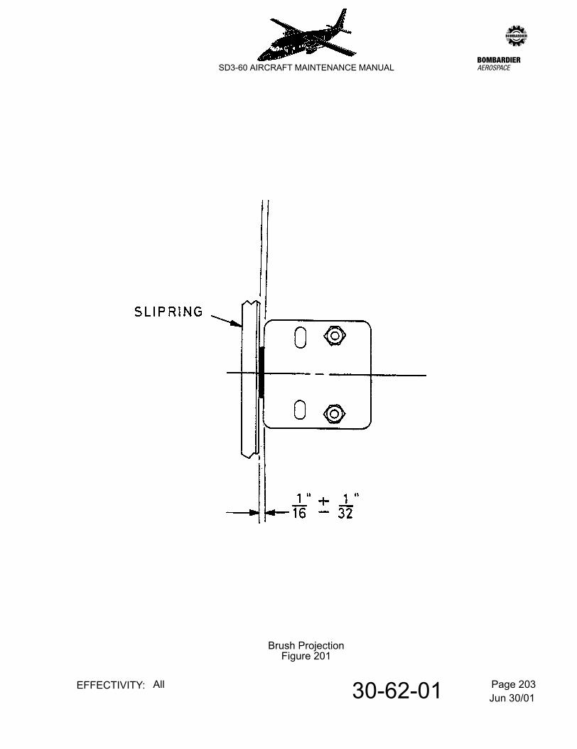
Jun 30/0130-62-01 Page 203EFFECTIVITY: All
zSD3-60 AIRCRAFT MAINTENANCE MANUAL
Brush ProjectionFigure 201
Jun 30/0130-80-00 Page 1EFFECTIVITY: All
zSD3-60 AIRCRAFT MAINTENANCE MANUAL
AMM30-80-00 41.0.0.0ICE DETECTION - GENERAL
1. General
Detection of ice is by a rotary ice detector. Refer to 30-81-00, pb1.
The presence of ice can be confirmed by a visual inspection of the leading edges. In darkness this is facilitated by the use of a spotlight. Refer to 33-44-00, pb1.
Jun 30/0130-81-00 Page 1EFFECTIVITY: All
zSD3-60 AIRCRAFT MAINTENANCE MANUAL
AMM30-81-00 42.0.0.0ICE DETECTION SYSTEM - DESCRIPTION & OPERATION
1. General
A Lucas Aerospace Limited Mk.3 rotary ice detector unit is mounted on the bottom of the nose fuselage at Stn. -5.50 and 7.3 in. to the left of the aircraft centreline.
A warning module is mounted on the pilots instrument panel 1P and an ON/OFF switch on the anti-icing panel 4P. Power to the warning module is supplied through the ice detector unit via circuit breaker No.180 in the right distribution panel 2D, from the 28V d.c. essential services busbar.
Power to the ice detector unit is supplied through the ON/OFF switch via circuit breaker No.364 in the right distribution panel 2D from the 115V 400 Hz busbar.
2. Description
The unit consists of an ac powered motor which drives, through a reduction gearbox, a serrated rotor. The rotor rotates in close proximity to a fixed knife edge cutter, which shaves the accretion of ice on the serrated rotor. The unit is mounted normal to the bottom nose skin of the aircraft, the serrated rotor and knife edge protruding through a suitably reinforced hole in the skin to be exposed to the airstream. Attachment is by four bolts through the detector end flange, a packing ring and the reinforced skin.
3. Operation
Under icing conditions, ice accretes on the rotor until the gap between the rotor and the cutter is filled. The shaving action of the ice causes a rise in motor torque and rotates the motor slightly. This movement operates a toggle bar against its spring tension to actuate a microswitch which connects a dc supply to illuminate an ICE warning caption on panel 1P.
Jun 30/0130-81-00 Page 201EFFECTIVITY: All
zSD3-60 AIRCRAFT MAINTENANCE MANUAL
AMM30-81-00 43.0.0.0ICE DETECTION SYSTEM - MAINTENANCE PRACTICES
1. Removal/Installation
Refer to Figure 201.
CAUTION: DO NOT DISTURB EXTERNAL BOLTS, NUTS OR SCREWS, OTHER THAN THE FOUR STRUCTURAL ATTACHMENT BOLTS, OR REMOVE SWITCH END COVER, OR ELSE THE ADJUSTMENT OF THE DETECTOR MAY BE SERIOUSLY IMPAIRED.
A. Remove rotary ice detector.
(1) Open circuit breakers No. 180 and No. 364 on panel 2D.
(2) Identify and disconnect all electrical cables from the detector unit.
(3) Remove attachment bolts and nuts and withdraw detector.
B. Install rotary ice detector
(1) Ensure that vent holes in the ice detector and the fuselage skin are clear. Position the ice detector so that the vent holes align with vent holes in the fuselage skin and packing piece. Fit the attachment bolts and nuts and tighten evenly.
CAUTION: DO NOT USE AN AIR JET TO CLEAR VENT HOLES IN THE ICE DETECTOR SINCE THIS WILL BLOW FOREIGN MATTER INWARD AND CAUSE DAMAGE TO THE MOTOR.
(2) Refer to Figure 201. Check the clearance between rotor and skin.
(3) Identify and connect the electrical cables to the terminal blocks.
(4) Close circuit breakers No. 180 and No. 364 on panel 2D.
(5) Functionally test the ice detector (para. 2).
2. Adjustment/Test
A. Function test (on aircraft)
(1) Energise 28V dc right essential services busbar and 115V 400 Hz busbar, both on right distribution panel 2D.
(2) Set the ICE DETection switch to ON (panel 4P).
(3) Check that the ice detector serrated rotor rotates in an anti-clockwise direction.
Equipment required: A torque test indicator: T360-30-01
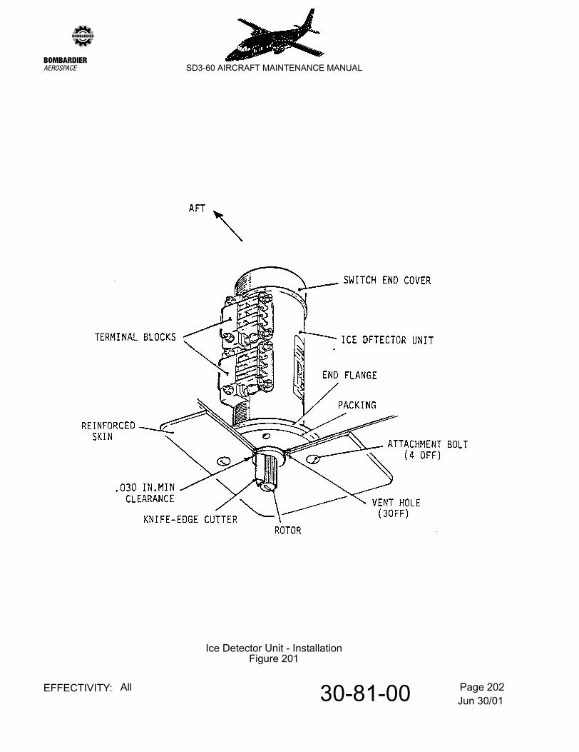
Jun 30/0130-81-00 Page 202EFFECTIVITY: All
zSD3-60 AIRCRAFT MAINTENANCE MANUAL
Ice Detector Unit - InstallationFigure 201
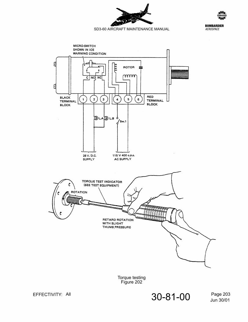
Jun 30/0130-81-00 Page 203EFFECTIVITY: All
zSD3-60 AIRCRAFT MAINTENANCE MANUAL
Torque testingFigure 202
Jun 30/0130-81-00 Page 204EFFECTIVITY: All
zSD3-60 AIRCRAFT MAINTENANCE MANUAL
(4) Refer to Figure 202. Insert the blade of a torque test indicator into the slot in the end face of the rotor and, with slight thumb pressure, apply a torque load. Check that the ICE warning light on the CWP is illuminated.
NOTE: The ice detection system should energise before sufficient torque is applied to cause the motor in the detector to labour.
(5) Release the torque load and check that the detector units internal microswitch resets open-circuit (ICE warning light extinguishes).
(6) Set the ICE DETection switch to OFF.
(7) De-energise the relevant busbars.
B. Function test (on bench)
Refer to Figure 202.
(1) Connect the ice detector in a test circuit.
(2) Close switch 1 and check that lamp A is on, and that lamp B is off.
(3) Insert the blade of a torque test indicator into the slot in the end face of the rotor and apply a slight thumb pressure torque until lamps A and B change over.
NOTE: The lamps should change over before sufficient torque is applied to cause the motor in the detector to labour.
(4) Open switch 1 and remove the detector from the test circuit.