SD3-60 AIRCRAFT MAINTENANCE MANUAL - Air Cargo Carriers 57.pdf · SD3-60 AIRCRAFT MAINTENANCE...
48
Apr 03/15 57 - CONTENTS Page 1 EFFECTIVITY: All z SD3-60 AIRCRAFT MAINTENANCE MANUAL CHAPTER 57 - WINGS TABLE OF CONTENTS 57-00-00 WINGS - GENERAL Description 1 57-00-01 WING AND WING STRUT LEADING EDGES - MAINTENANCE PRACTICES General 201 Servicing 201 Removal 202 57-00-06 HINGE ARMS (AILERON AND FLAP) - MAINTENANCE PRACTICES Servicing 201 Repair 201 57-00-11 WING TRAILING EDGE SHROUDS - MAINTENANCE PRACTICES Adjustment/Test 201 Repair 203 57-00-16 WING STRUT - MAINTENANCE PRACTICES Removal/Installation 201 57-00-21 OUTER WING - REMOVAL/INSTALLATION General 401 Removal 401 Installation 403 57-10-01 CONTROLLED TORQUE TIGHTENING OF CENTRE WING TO FUSELAGE ATTACHMENT BOLTS General 1 57-40-01 WING/NACELLE ATTACHMENT LUGS (REAR SPAR) - INSPECTION/ CHECK Applicability 601 Purpose 601 Special Tools and Equipment 601 Job Set-Up Information for Surface Scan 602 Job Set-Up Information for Rotary Scan 602 Acceptance Criteria 605 Reporting Procedure 605 Chapter Section Subject Subject Page
Transcript of SD3-60 AIRCRAFT MAINTENANCE MANUAL - Air Cargo Carriers 57.pdf · SD3-60 AIRCRAFT MAINTENANCE...
Apr 03/1557 - CONTENTS Page 1EFFECTIVITY: All
zSD3-60 AIRCRAFT MAINTENANCE MANUAL
CHAPTER 57 - WINGS
TABLE OF CONTENTS
57-00-00 WINGS - GENERALDescription 1
57-00-01 WING AND WING STRUT LEADING EDGES - MAINTENANCE PRACTICES
General 201Servicing 201Removal 202
57-00-06 HINGE ARMS (AILERON AND FLAP) - MAINTENANCE PRACTICESServicing 201Repair 201
57-00-11 WING TRAILING EDGE SHROUDS - MAINTENANCE PRACTICESAdjustment/Test 201Repair 203
57-00-16 WING STRUT - MAINTENANCE PRACTICESRemoval/Installation 201
57-00-21 OUTER WING - REMOVAL/INSTALLATIONGeneral 401Removal 401Installation 403
57-10-01 CONTROLLED TORQUE TIGHTENING OF CENTRE WING TO FUSELAGE ATTACHMENT BOLTS
General 1
57-40-01 WING/NACELLE ATTACHMENT LUGS (REAR SPAR) - INSPECTION/CHECK
Applicability 601Purpose 601Special Tools and Equipment 601Job Set-Up Information for Surface Scan 602Job Set-Up Information for Rotary Scan 602Acceptance Criteria 605Reporting Procedure 605
ChapterSectionSubject Subject Page
Apr 03/1557 - CONTENTS Page 2EFFECTIVITY: All
zSD3-60 AIRCRAFT MAINTENANCE MANUAL
Close Out 605Repeat Procedure 606
57-40-06 BOTTOM SHEAR DECK (POST MOD A8662) - INSPECTION/CHECKApplicability 601Purpose 601Special Tools and Equipment 601Job Set-Up Information for Surface Scan 601Job Set-Up Information for Rotary Scan 603Acceptance Criteria 603Reporting Procedure 604Close Out 604Repeat Procedure 604
57-50-01 AILERON & TAB - REMOVAL/INSTALLATIONGeneral 401Tab 401Aileron 402
57-50-06 INNER FLAP - REMOVAL/INSTALLATIONGeneral 401Inner flap 401
57-50-11 MID FLAP - REMOVAL/INSTALLATIONGeneral 401Mid flap 401
57-50-16 OUTER FLAP - REMOVAL/INSTALLATIONGeneral 401Outer flap 401
Jun 30/0157-00-00 Page 1EFFECTIVITY: All
zSD3-60 AIRCRAFT MAINTENANCE MANUAL
AMM57-00-00 1.0.0.0WINGS - GENERAL
1. Description
A. General
The all-metal stressed-skin wing is manufactured in three sections; a centre wing which extends 140.75 inches on either side of the centre line of the aircraft and two outer wings, left and right; each of 298.25 inches in length overall. The outer wings are pinned to the ends of the centre wing and are braced by wing struts. The wing leading edge is designed to safeguard against bird impact.
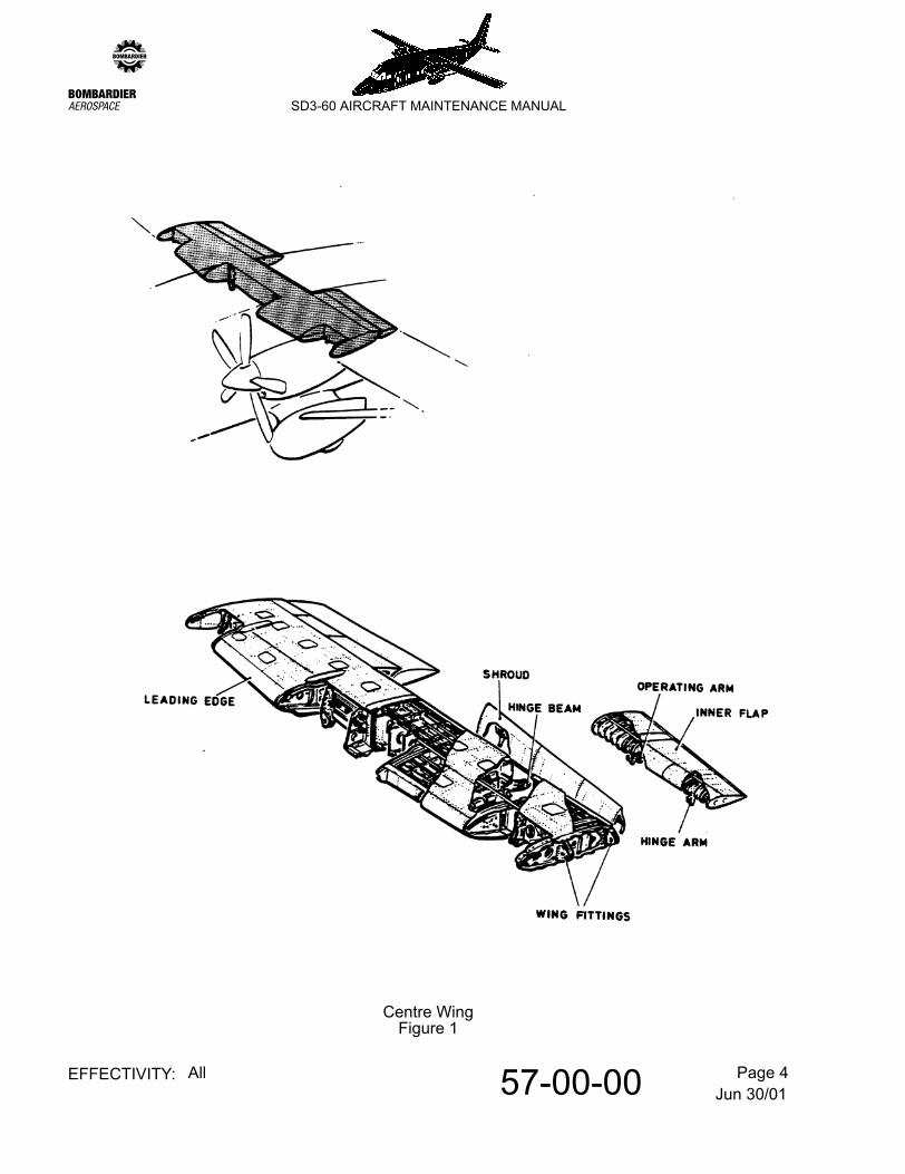
B. Centre wing
Refer to Figure 1.
The centre wing is attached to the fuselage at the front and rear spars, and consists of a continuous single cell box beam with locally reinforced leading edge nose sections between the nacelles and fuselage. Also included are the trailing edge flap shrouds and surfaces.
The box beam is of constant width and varying depth and comprises a front and rear spars and upper and lower skins reinforced by stringers and internal ribs.
The front spar web has a manufacturing joint at the centre line and is reinforced locally at system penetration and inspection holes. At a station 40 inches either side of the centre line, the web carries the upper half of the wing/fuselage joint.
At each extremity the front spar web supports the inner half of the centre/outer wing joint. The frontspar top and bottom booms, fabricated from formed angles, are continuous across the centre line.
The rear spar is of similar construction to the front spar but has no lateral reinforcing members. The rear spar supports the trailing edge flap shrouds and surfaces.
Twenty three ribs are provided and they comprise, in the main, sheet metal webs, stiffeners and booms. Discreet ribs support the flap hinge arms and the engine mounting structure and carry wing/fuselage joint loads and air loads.
The leading edge nose sections have reinforced skins and ribs to increase local wing torsional stiffness and to safeguard against bird impact.
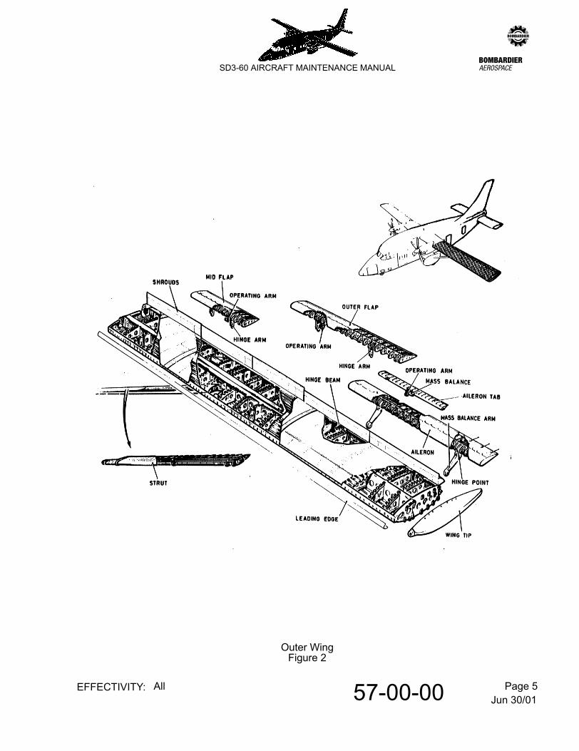
C. Outer wing
Refer to Figure 2.
The outer wing is a simple two cell beam of constant cross section which extends over a length of almost 300 inches. The beam is supported by pin attachments to the centre wing and left strut. These joints are of multiple lug construction and are designed to be fail safe.
Jun 30/0157-00-00 Page 2EFFECTIVITY: All
zSD3-60 AIRCRAFT MAINTENANCE MANUAL
The beam in turn support the flight control surfaces and the wing tip.
The main structural elements of the beam comprise three spars separated by a number of ribs. This open cell arrangement is closed by upper, lower and leading edge skins.
The front spar is manufactured from pressed channel sections and is reinforced at joints, rib intrusions and inspection holes. At the inboard end machined fittings are attached to provide the outer half of the centre/outer wing joints.
The rear spar is of similar construction to the front spar except that web is not pierced for rib intrusions. It is reinforced locally to satisfy the flap jack installation. The rear spar supports the trailing-edge flap shrouds and surfaces.
The leading-edge spar is an auxiliary pressed channel member forming the forward boundary of the forward cell and supports the leading edge skin.
The leading edge skin and supporting structure are reinforced to safeguard against bird impact. Boot de-icing is provided along the leading edge.
D. Wing strut
The strut comprises three spars connected by a series of ribs and covered with three local skins either side to form a fail safe structure. The leading edge is reinforced to safeguard against bird impact. A fitting is attached to the ends of each spar to carry the attachment pins.
E. Flaps
The flaps are of single slotted design and there are three flap segments on each side - inner, mid and outer. The inner flap segment on each side is carried by the centre wing and the mid and outer flap segments on each side are carried by the outer wings. Flap segments are of conventional form comprising sheet metal spar, ribs, trailing edge member and skins. Each flap segment is supported by two fail-safe hinge beams. The section of each beam, in the form of a box section is attached to the wing lower surface and the aft end of the beam provides a fail-safe fork lug. The hinge arm houses a bearing and passes through a slot in the flap skin adjacent to nose ribs within the flap. A fail-safe bush and bolt connect the hinge beam and arm together. Each flap segment is operated by a rod adjacent to a hinge arm. The mid and outer flaps are connected by an emergency pin.
F. Ailerons
The slotted ailerons are similar in construction to the flaps except that sub spars are provided local at the fail-safe hinge arms. Each aileron has two external mass balance arms supported from the hinges. The operating rod is adjacent to the inboard hinge. Each aileron has a tab supported off three hinges. It is balanced by mass balance weights supported off its leading edge.
Jun 30/0157-00-00 Page 3EFFECTIVITY: All
zSD3-60 AIRCRAFT MAINTENANCE MANUAL
G. Flap and aileron shrouds
The shrouds for the flaps and the aileron are of conventional construction. The flap shrouds are hinged along the upper surface at their junction with the rear spar.
For the aileron shrouds the outboard one is hinged along the upper surface at its junction with the rear spar and the inboard one is hinged along the lower and upper surface at its junction with the rear spar.
These shrouds provide access to flap and aileron controls and also facilitate inspection of wing internal structure.
H. Wing tip
The wing tip is manufactured as a one piece fibreglass shell. The wing tip is bolted around its perimeter to the wing skin. It houses the navigation light.
I. Strut-to-wing fairing
The fibreglass fairing supports a landing lamp at its forward end. It is cut-away in way of the strut upper skin surface to allow installation with a closing member. At the fairing interface with the lower wing surface a rubber sealing strip is attached.
Jun 30/0157-00-00 Page 4EFFECTIVITY: All
zSD3-60 AIRCRAFT MAINTENANCE MANUAL
Centre WingFigure 1
Jun 30/0157-00-00 Page 5EFFECTIVITY: All
zSD3-60 AIRCRAFT MAINTENANCE MANUAL
Outer WingFigure 2
Jun 30/0157-00-01 Page 201EFFECTIVITY: All
zSD3-60 AIRCRAFT MAINTENANCE MANUAL
AMM57-00-01 2.0.0.0WING AND WING STRUT LEADING EDGES - MAINTENANCE PRACTICES
1. General
Aircraft to Post mod 7615 standard have abrasion resistant tape (Pt. No. Y8561) applied to the leading edges of the wing struts, and to the inner wings (aircraft with De-icing boots fitted) or the complete wings (aircraft with no De-icing boots fitted). Horizontal Stabilizer leading edges are described. Refer to 55-10-00, pb1.
2. Servicing
A. Cleaning procedure
(1) Flush the tape with clean water to remove loose dirt particles.
(2) Wash with a brush, rag or sponge using detergent such as 'Dreft', 'Vel' or 'Surf'.
(3) Rinse the entire area with clean water and allow to dry naturally.
(4) If, after completing the above procedures, tar, oil diesel smut or bituminous material remain, proceed as follows:-
(a) Wipe the affected area with a rag dampened with Kerosene, mineral spirits, heptane, or VM &P Naphtha as required.
(5) Contamination which cannot be removed by either of the above procedures may be removed by scrubbing with a 'Scotchbrite' brand pad or steel wool, using a commercial cleaner and rinsing with clean water.
B. Repair
NOTE: Depending upon substrate, extent of damage, and length of exposure, it may be necessary to replace the complete tape. However, in certain cases, the useful life of the tape can be extended to the normal durability limit by repair, as follows:-
(1) Trim any loose areas of tape, and ensure the local region is cleaned before patching.
NOTE: Patches are to be larger than the area to be covered, overlapping the undamaged area by at least 1/4 in. (6 mm) on all edges.
(2) Position the patch over the trimmed area and hinge in place with 'Scotch' brand masking tape.
(3) Remove the paper backing and squeegee firmly into place using a plastic applicator. Remove 'Scotch' tape and resqueegee all edges.
Jun 30/0157-00-01 Page 202EFFECTIVITY: All
zSD3-60 AIRCRAFT MAINTENANCE MANUAL
3. Removal
NOTE: The following procedure is recommended for the removal of abrasion resistant tape (Pt. No. Y8561).
CAUTION: THE FOLLOWING PROCEDURE REQUIRES THE USE OF METHYLENE CHLORIDE BASE PAINT REMOVERS (SUCH AS 'OAKITE 157' 'CEE BEE A292' AND STRYPEEZE). THESE PRODUCTS MUST BE USED SPARINGLY, IN AVOIDANCE OF REMOVAL OR DAMAGE OF PAINT, UNDER OR NEAR THE TAPE.
A. Mask around the tape, leaving a gap of 1/64 in. (0.4 mm) between the masking tape and edge of protective tape.
CAUTION: MOST FINISH REMOVING MATERIALS CONTAIN CHEMICALS HARMFUL TO SKIN AND EYES. THE MANUFACTURERS SAFETY PRECAUTIONS MUST BE FOLLOWED DURING TAPE REMOVING PROCEDURES.
B. Brush on paint remover sparingly, starting at the top of the film. After a few seconds, as the tape loosens, scrape downwards with a scraper blotting up the loosened material with rags. Repeat this procedure until the adhesive coat of the tape is softened.
C. Wipe off all traces of paint remover.
CAUTION: (1) IN THE FOLLOWING PROCEDURE, THE USE OF SOLVENTS REQUIRE THAT PROPER PRECAUTIONARY MEASURES BE OBSERVED. THESE INCLUDE, BUT ARE NOT RESTRICTED TO:-
(A) WORK ONLY IN A WELL VENTILATED AREA.
(B) KEEP AWAY FROM HEAT, SPARKS, AND OPEN FLAMES.
(C) NO SMOKING IN THE WORK AREA.
(D) AVOID BREATHING VAPOURS.
(E) AVOID EYE AND PROLONGED SKIN CONTACT.
(F) KEEP SOLVENT CONTAINERS CLOSED WHEN NOT IN USE.
D. Complete the removal of softened adhesive with a solvent mixture of 75% MEK - 25% tolune.
E. Rinse thoroughly with clean water.
Jun 30/0157-00-06 Page 201EFFECTIVITY: All
zSD3-60 AIRCRAFT MAINTENANCE MANUAL
AMM57-00-06 3.0.0.0HINGE ARMS (AILERON AND FLAP) - MAINTENANCE PRACTICES
1. Servicing
A. Inspect external dope patches
If on inspection any dope patch is seen to be damaged or missing (with consequent risk of rain ingress), replace patch/es as detailed in Para. 2.A.
2. Repair
A. Replace/install external dope patches
(1) Thoroughly clean structure around affected flange lightning hole/s to remove any dope patch residue from previous installation.
(2) Seal lightning hole/s using a 3 in. wide piece of fabric patch (BS7F1-5C or MIL-C-5646) with aircraft dope (BSx26 or MIL-D-5553A), or, 3M Abrasion Resistant Film (Pt. No. 8560), or, 3M Aluminium foil, Pt. No. Y434 (Speedtape).
NOTE: Part Nos. 8560 and Y434 can be obtained from:-
Industrial Specialties Division/3MBuilding 220-7E3M CenterSt. PaulMinnesota 55144U.S.A.
or
3M Company U.K. Limited3M HouseWigmore StreetLONDON W1A 1ETEngland
Jun 30/0157-00-11 Page 201EFFECTIVITY: All
zSD3-60 AIRCRAFT MAINTENANCE MANUAL
AMM57-00-11 4.0.0.0WING TRAILING EDGE SHROUDS - MAINTENANCE PRACTICES
1. Adjustment/Test
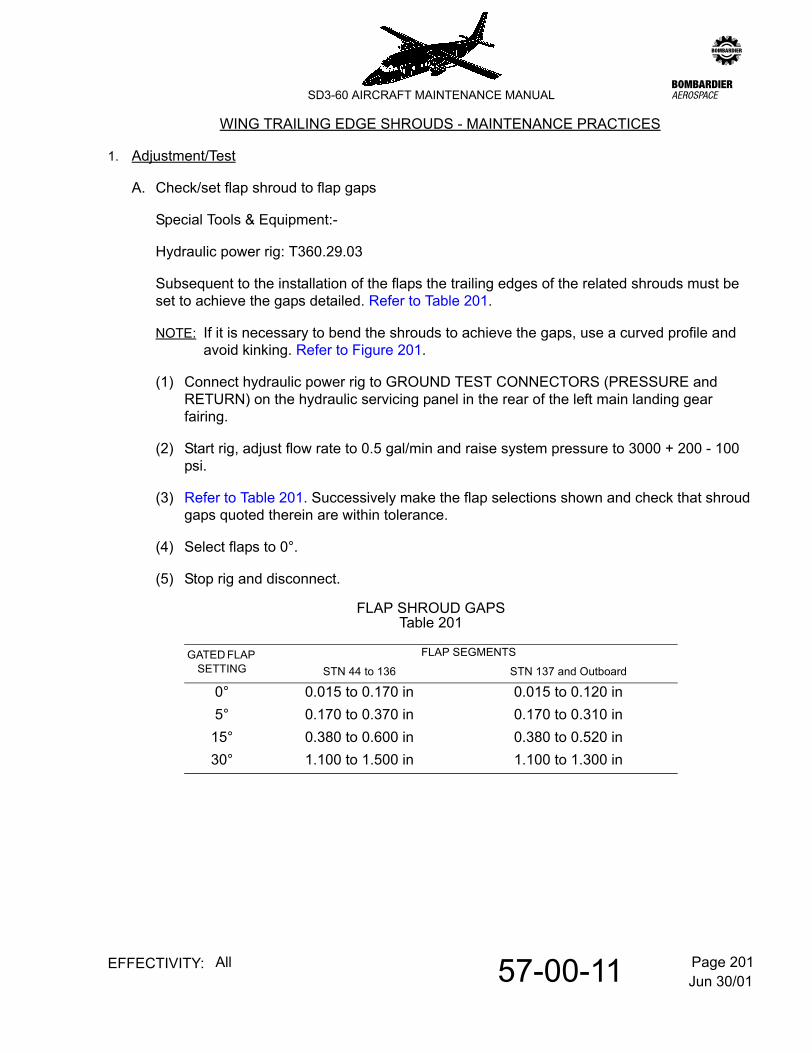
A. Check/set flap shroud to flap gaps
Special Tools & Equipment:-
Hydraulic power rig: T360.29.03
Subsequent to the installation of the flaps the trailing edges of the related shrouds must be set to achieve the gaps detailed. Refer to Table 201.
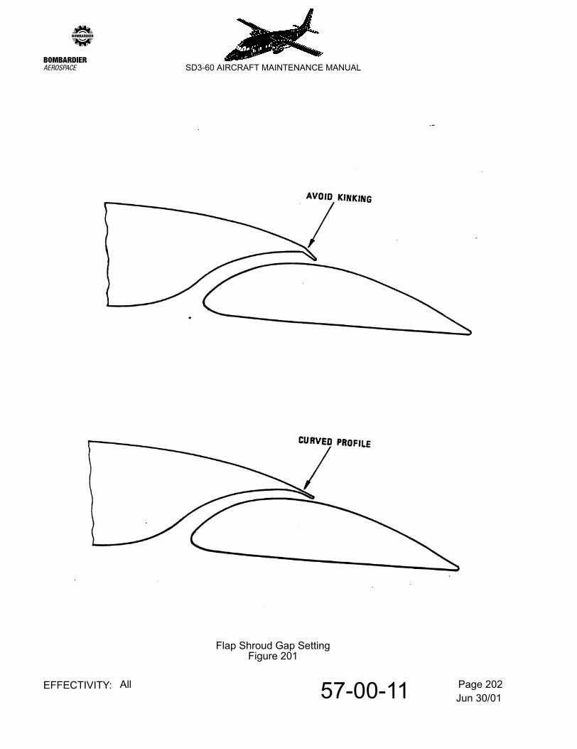
NOTE: If it is necessary to bend the shrouds to achieve the gaps, use a curved profile and avoid kinking. Refer to Figure 201.
(1) Connect hydraulic power rig to GROUND TEST CONNECTORS (PRESSURE and RETURN) on the hydraulic servicing panel in the rear of the left main landing gear fairing.
(2) Start rig, adjust flow rate to 0.5 gal/min and raise system pressure to 3000 + 200 - 100 psi.
(3) Refer to Table 201. Successively make the flap selections shown and check that shroud gaps quoted therein are within tolerance.
(4) Select flaps to 0°.
(5) Stop rig and disconnect.
FLAP SHROUD GAPSTable 201
GATED FLAP SETTING
FLAP SEGMENTS
STN 44 to 136 STN 137 and Outboard
0° 0.015 to 0.170 in 0.015 to 0.120 in5° 0.170 to 0.370 in 0.170 to 0.310 in15° 0.380 to 0.600 in 0.380 to 0.520 in30° 1.100 to 1.500 in 1.100 to 1.300 in
Jun 30/0157-00-11 Page 202EFFECTIVITY: All
zSD3-60 AIRCRAFT MAINTENANCE MANUAL
Flap Shroud Gap SettingFigure 201
Jun 30/0157-00-11 Page 203EFFECTIVITY: All
zSD3-60 AIRCRAFT MAINTENANCE MANUAL
2. Repair
A. Replace damaged sealing tape.
Operational experience has shown that the appearance of the original sealing tape on the wing shroud hinges (of aircraft production Ser. Nos. up to and including SH3647) deteriorates in service. This procedure replaces the existing aluminium speed tape with polyurethane clear tape (introduced by Mod 7639 and Serv. Bull. SD360-57-01).
NOTE: The procedure is applicable to the left and right wings. Specific information for the right wing is contained in parentheses.
Materials required:
(1) Remove existing tape
Refer to Figure 202.
WARNING: DO NOT LET REMOVED MATERIALS GO INTO THE FLIGHT CONTROL SYSTEM. LOOSE MATERIAL CAN CAUSE A SUBSEQUENT JAM IN THE FLIGHT CONTROLS.
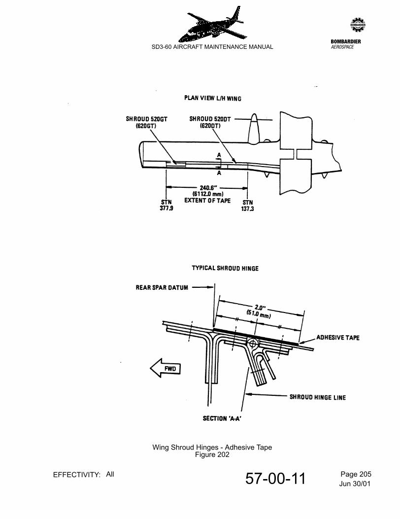
(a) Remove and discard the seating tape from the left (right) wing top surface between:
- STN137.9 the inboard end of shroud 520DT (620DT)- STN377.9 the outboard end of shroud 520GT (620GT)
WARNING: DO NOT GET THE CLEANING AGENT ON YOUR ON YOUR SKIN OR IN YOUR EYES. USE THE CLEANING AGENT IN A WELL VENTILATED AREA. DO NOT BREATHE THE GAS.
PUT ON PROTECTIVE CLOTHING, GOGGLES AND A FACE MASK WHEN YOU USE THIS CLEANING AGENT. IF YOU GET THE CLEANING AGENT ON YOUR SKIN OR IN YOUR EYES, FLUSH WITH CLEAN WATER. GET MEDICAL HELP IF YOUR SKIN BECOMES IRRITATED.
(b) Use the lint-free cloth with MEK to remove all, residual adhesive.
(c) Clean the adjacent area. Make sure the area is clean and all oil or grease is removed.
Part No. Description Quantity
Lint-free cloth A/Rv Methyl Ethyl Ketone (MEK) A/R
3M Polyurethane clear tape one rollType 8560 2.0" (51.0 mm) wide
Jun 30/0157-00-11 Page 204EFFECTIVITY: All
zSD3-60 AIRCRAFT MAINTENANCE MANUAL
(2) Apply sealing tape
Refer to Figure 202.
(a) Make sure the work area is clean and dry.
(b) Carefully apply clear polyurethane tape to the shroud hinge area between:
- STN137.9 the inboard end of shroud 520DT (620DT)- STN377.9 the outboard end of shroud 520GT (620GT)
1 1 Make sure the polyurethane tape is located equally forward and aft of the shroud hinge line.
2 2 At the end of every shroud, cut the polyurethane tape up to the shroud hinge line.
NOTE: This allows every shroud to be opened and closed independently.
(c) Use a dry lint-free cloth and remove all air-bubbles from the polyurethane tape.
(d) Remove all tools, materials and equipment from the work area. Make sure that the area is clean.
Jun 30/0157-00-11 Page 205EFFECTIVITY: All
zSD3-60 AIRCRAFT MAINTENANCE MANUAL
Wing Shroud Hinges - Adhesive TapeFigure 202
Dec 18/0757-00-16 Page 201EFFECTIVITY: All
zSD3-60 AIRCRAFT MAINTENANCE MANUAL
AMM57-00-16 1.0.0.0WING STRUT - MAINTENANCE PRACTICES
1. Removal/Installation
Special Tools and equipment:-
- Bullet Alignment (strut/wing assembly): T360-51-03- Bullet Alignment (strut/stub wing assembly): T360-51-04
CAUTION: THE AIRCRAFT AND THE APPLICABLE OUTER WING MUST BE CORRECTLY SUPPORTED USING THE SPECIFIED EQUIPMENT, BEFORE REMOVAL OF A WING STRUT.WHEN THE STRUT IS DISCONNECTED AT ONE OF THE TWO ENDS, THE OUTER WING IS FREE TO PIVOT ABOUT THE CENTRE WING-TO-OUTER WING ATTACHMENT AND MAY CAUSE DAMAGE TO ADJACENT STRUCTURE AND THE VARIOUS SYSTEMS THAT GO ACROSS THE CENTRE WING AND OUTER WING. THESE SYSTEMS INCLUDE PRIMARY AND SECONDARY AILERON CONTROLS, FLAP SIGNALLING CABLES AND FLAP HYDRAULIC PIPELINES.
ALSO, A FREEDOM OF MOVEMENT CHECK ON THE PRIMARY AND SECONDARY AILERON CONTROLS SHALL BE DONE BEFORE THE STRUT IS DISCONNECTED, AND THEN AFTER IT IS CONNECTED AGAIN, TO ASSESS BY COMPARISON, THAT DAMAGE HAS NOT OCCURRED.
A. Remove a strut
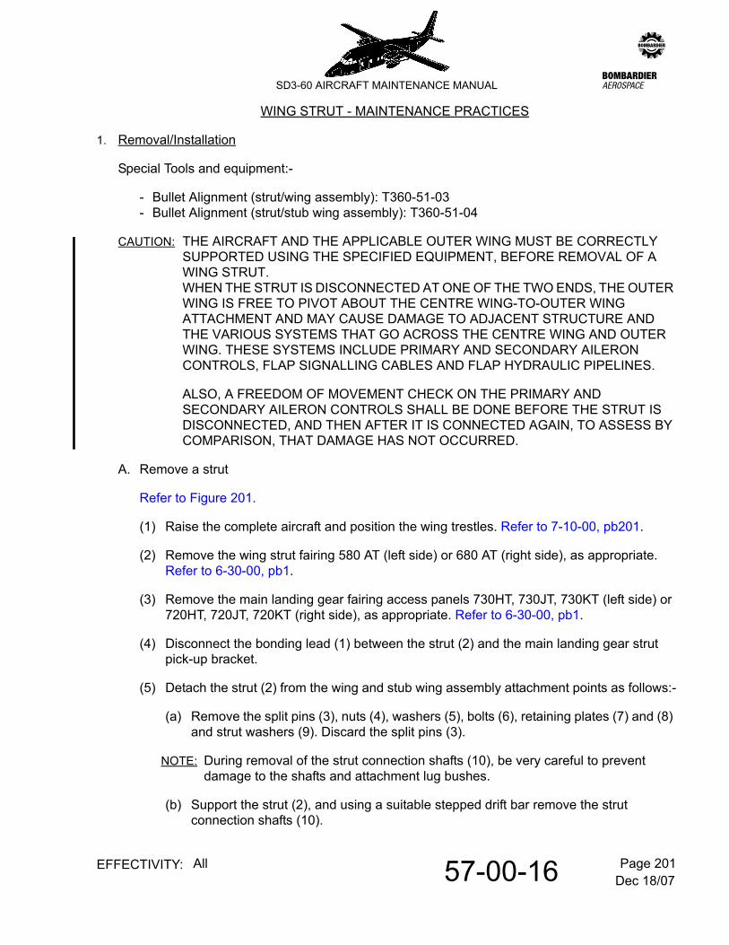
Refer to Figure 201.
(1) Raise the complete aircraft and position the wing trestles. Refer to 7-10-00, pb201.
(2) Remove the wing strut fairing 580 AT (left side) or 680 AT (right side), as appropriate. Refer to 6-30-00, pb1.
(3) Remove the main landing gear fairing access panels 730HT, 730JT, 730KT (left side) or 720HT, 720JT, 720KT (right side), as appropriate. Refer to 6-30-00, pb1.
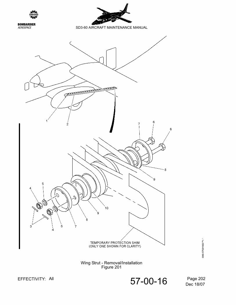
(4) Disconnect the bonding lead (1) between the strut (2) and the main landing gear strut pick-up bracket.
(5) Detach the strut (2) from the wing and stub wing assembly attachment points as follows:-
(a) Remove the split pins (3), nuts (4), washers (5), bolts (6), retaining plates (7) and (8) and strut washers (9). Discard the split pins (3).
NOTE: During removal of the strut connection shafts (10), be very careful to prevent damage to the shafts and attachment lug bushes.
(b) Support the strut (2), and using a suitable stepped drift bar remove the strut connection shafts (10).
Dec 18/0757-00-16 Page 202EFFECTIVITY: All
zSD3-60 AIRCRAFT MAINTENANCE MANUAL
Wing Strut - Removal/InstallationFigure 201
Dec 18/0757-00-16 Page 203EFFECTIVITY: All
zSD3-60 AIRCRAFT MAINTENANCE MANUAL
B. Install a strut
Refer to Figure 201.
NOTE: Before the installation of the strut to the wing and stub wing assembly, make sure that any protective treatments that were removed (i.e. chipped to expose bare metal) are restored. Refer to SRM 51-23-00, pb1, para. 10 (as appropriate).
To prevent contact of the lug faces during installation of the strut connection shaft, which could cause damage to the protective treatment, it is recommended that temporary protection shims (made from wood, plastic, or equivalent applicable material) be inserted between the faces.
(1) Attach the strut (2) to the wing and stub wing assembly attachment points as follows:-
(a) Position the strut (2) at the wing and stub wing assembly attachment points, fit temporary protective shims (11) as applicable, and align the attachment lug bushes using the appropriate bullet alignment tool.
(b) Install the strut connection shafts (10) and secure with the bolts (6), strut washers (9), retaining plates (8) and (7), washers (5) and nuts (4).
(c) Torque the nuts (4) to 20 lbf·in (2.26 N·m) and safety lock with new split pins (3), Pt. No. SP90-C6. Apply green putty witness marks to the nuts (4) to show the torque setting. Refer to 20-09-06, pb1.
(d) Remove the temporary protection shims (11).
(2) Connect the bonding lead (1) between the strut (2) and the main landing gear strut pick-up bracket.
(3) Refit the main landing gear fairing access panels 730HT, 730JT, 730KT (left side) or 720HT, 720JT, 720KT (right side), as appropriate.
(4) Refit the wing strut fairing 580AT (left side) or 680AT (right side), as appropriate.
(5) Remove the wing trestles and lower the aircraft. Refer to 7-10-00, pb201.
Jun 30/0157-00-21 Page 401EFFECTIVITY: All
zSD3-60 AIRCRAFT MAINTENANCE MANUAL
AMM57-00-21 6.0.0.0OUTER WING - REMOVAL/INSTALLATION
1. General
CAUTION: ALL PIPE CONNECTIONS, ELECTRICAL PLUGS AND SOCKETS AND ACCESSORY DRIVE PADS MUST BE FITTED WITH BLANKS IMMEDIATELY ON REMOVAL; CONVERSELY, WHEN INSTALLING ENSURE THAT THE BLANKS ARE REMOVED.
ENSURE THAT PIPES ARE CORRECTLY CLIPPED ON RE-INSTALLATION TO PREVENT FRETTING ON ADJACENT COMPONENTS.
ALL PRE-FORMED PACKING O-RINGS AND GASKETS FREED OR EXPOSED DURING REMOVAL OPERATIONS ARE TO BE DISCARDED AND NEWLY REPLACED ON RE-ASSEMBLY. (WHEN REPLACING, LUBRICATE WITH FLUID TO BE USED IN APPROPRIATE SYSTEM OR LINE).
UNLESS OTHERWISE STATED, ALL PIPE UNIONS AND ADAPTERS SHOULD BE TIGHTENED. REFER TO 20-09-04, PB1.
NOTE: Bonding leads freed during removal operations are to be re-attached at a convenient stage during installation. Refer to 20-09-05, pb1.
Special Tools and Equipment:-
- Sling, wing outer- Bullet alignment (outer wing/centre wing assy) T360.51.01
2. Removal
A. Remove an outer wing
(1) Carry out Aircraft symmetry check and record dimensions for future use. Refer to 51-00-00, pb201.
(2) Remove lift strut fairings (4 off). Panel No 680 and 720HT, 720JT, 720KT and stow.
(3) Remove outer to centre wing joint panels. Panel No's 610TT, 610BB, 610HT stow panels.
(4) Open trailing edge shrouds. Panel No's 620AT, 620BT, 620CT and 620DT.
(5) Render aircraft electrically safe. Refer to 12-09-03, pb301.
(6) Release all reservoir and accumulator pressures.
(7) The following electrical systems should be disconnected as per SD3-60 Wiring Manual at the wing break.
(a) Stall Warning (27-33-00)
Jun 30/0157-00-21 Page 402EFFECTIVITY: All
zSD3-60 AIRCRAFT MAINTENANCE MANUAL
(b) Landing Lights (33-41-00)
(c) Nav/Strobe Lights (33-42-00)
(d) Gyro Compass (34-21-00)
(e) Pneumatic De-icing (30-11-00)
(8) Remove inner flap assembly. Refer to 57-50-06, pb401. Label and stow as necessary.
(9) Remove mid flap assembly. Refer to 57-50-11, pb401. Label and stow as necessary.
(10) Remove outer flap assembly. Refer to 57-50-16, pb401. Label and stow as necessary.
(11) Remove aileron and tab assembly. Refer to 57-50-01, pb401. Label and stow as necessary.
(12) Disconnect and remove aileron control rods from control surface down to centre wing section, number, label and stow. Retain nut, collar and bolt.
(13) Disconnect flap, signalling cables. Clamp cable at convenient position on centre wing section. Label and stow as necessary.
(14) Disconnect aileron trim cables. Clamp at convenient position on centre wing section. Label as necessary.
(15) Disconnect flap actuator hydraulic pipes at centre to outer wing break. Blank all open ends.
(16) Disconnect de-ice boot air supply pipe work at centre wing position and blank pipes. Retain any items removed.
(17) Position aircraft for wing removal.
(18) Raise the complete aircraft up on jacks and trestle. Refer to 7-10-00, pb201.
(19) Place a Ballast of 400 Ibs. in the forward cargo bay.
(20) Place Left and Right wing supports in position.
(21) Prepare lift strut to be removed. Refer to 57-00-16, pb201.
(22) Prepare outer wing attachment points for removal.
(23) Attach lifting sling to wing. Extreme care must be taken, take up slack.
(24) Remove lift strut. Refer to 57-00-16, pb201.
Jun 30/0157-00-21 Page 403EFFECTIVITY: All
zSD3-60 AIRCRAFT MAINTENANCE MANUAL
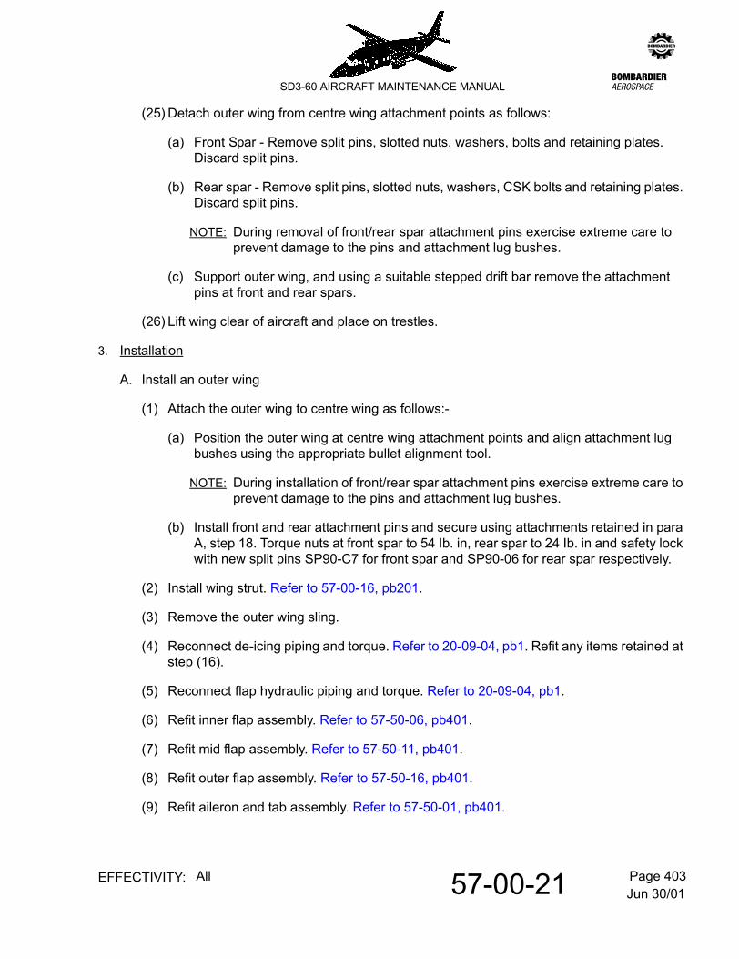
(25) Detach outer wing from centre wing attachment points as follows:
(a) Front Spar - Remove split pins, slotted nuts, washers, bolts and retaining plates. Discard split pins.
(b) Rear spar - Remove split pins, slotted nuts, washers, CSK bolts and retaining plates. Discard split pins.
NOTE: During removal of front/rear spar attachment pins exercise extreme care to prevent damage to the pins and attachment lug bushes.
(c) Support outer wing, and using a suitable stepped drift bar remove the attachment pins at front and rear spars.
(26) Lift wing clear of aircraft and place on trestles.
3. Installation
A. Install an outer wing
(1) Attach the outer wing to centre wing as follows:-
(a) Position the outer wing at centre wing attachment points and align attachment lug bushes using the appropriate bullet alignment tool.
NOTE: During installation of front/rear spar attachment pins exercise extreme care to prevent damage to the pins and attachment lug bushes.
(b) Install front and rear attachment pins and secure using attachments retained in para A, step 18. Torque nuts at front spar to 54 Ib. in, rear spar to 24 Ib. in and safety lock with new split pins SP90-C7 for front spar and SP90-06 for rear spar respectively.
(2) Install wing strut. Refer to 57-00-16, pb201.
(3) Remove the outer wing sling.
(4) Reconnect de-icing piping and torque. Refer to 20-09-04, pb1. Refit any items retained at step (16).
(5) Reconnect flap hydraulic piping and torque. Refer to 20-09-04, pb1.
(6) Refit inner flap assembly. Refer to 57-50-06, pb401.
(7) Refit mid flap assembly. Refer to 57-50-11, pb401.
(8) Refit outer flap assembly. Refer to 57-50-16, pb401.
(9) Refit aileron and tab assembly. Refer to 57-50-01, pb401.
Jun 30/0157-00-21 Page 404EFFECTIVITY: All
zSD3-60 AIRCRAFT MAINTENANCE MANUAL
(10) Reconnect aileron control rod and secure using attachments retained in step (12). Safety lock with new split pin.
(11) Reconnect the aileron and flap control cables. Tension cables and lock turnbuckles. Refer to 20-09-01, pb1.
(12) Reconnect all electrical connections as per SD3-60 Wiring Manual, disconnected at step (7).
(13) Function test the navigation lights. Refer to 33-42-00, pb201.
(14) Function test the wing tip mounted strobe lights. Refer to 33-43-00, pb201.
(15) Function test the landing and taxi lights. Refer to 33-41-00, pb201.
(16) Function check the boot ejector valve anti-icing heater muffs. Refer to 30-12-00, pb201.
(17) Function test the aerofoil de-icing system and check for leaks at reconnected pipe joints. Refer to 30-11-00, pb201.
(18) Function check the stall warning system as applicable.
- Pre mod A8005. Refer to 27-33-00, pb201.- Post mod A8005. Refer to 27-34-00, pb201.
(19) Function check flap position indication. Refer to 27-52-00, pb201.
(20) Function compass system
- Pre mod A8062. Refer to 34-21-10, pb201.- Post mod A8062. Refer to 34-21-20, pb201.
(21) Function test aileron primary controls. Refer to 27-11-00, pb201.
(22) Function test the aileron trim controls. Refer to 27-12-00, pb201.
(23) Inflate all reservoir and accumulator pressures.
(24) Function test the flap controls. Refer to 27-51-00, pb201.
(25) Refit access panels and secure shrouds.
(26) Restore electrical power.
Jun 30/0157-10-01 Page 1EFFECTIVITY: All
zSD3-60 AIRCRAFT MAINTENANCE MANUAL
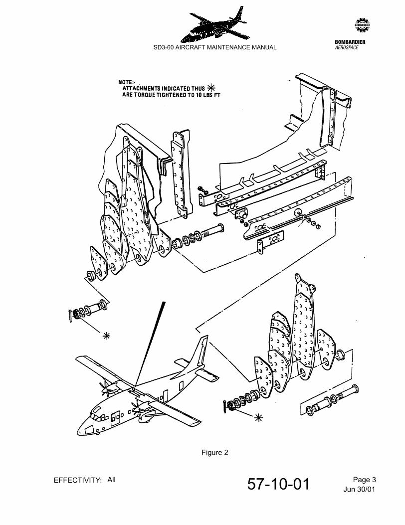
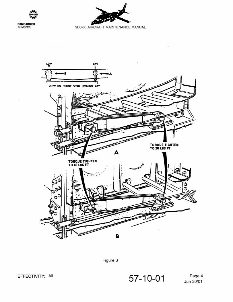
AMM57-10-01 7.0.0.0CONTROLLED TORQUE TIGHTENING OF CENTRE WING TO FUSELAGE ATTACHMENT BOLTS
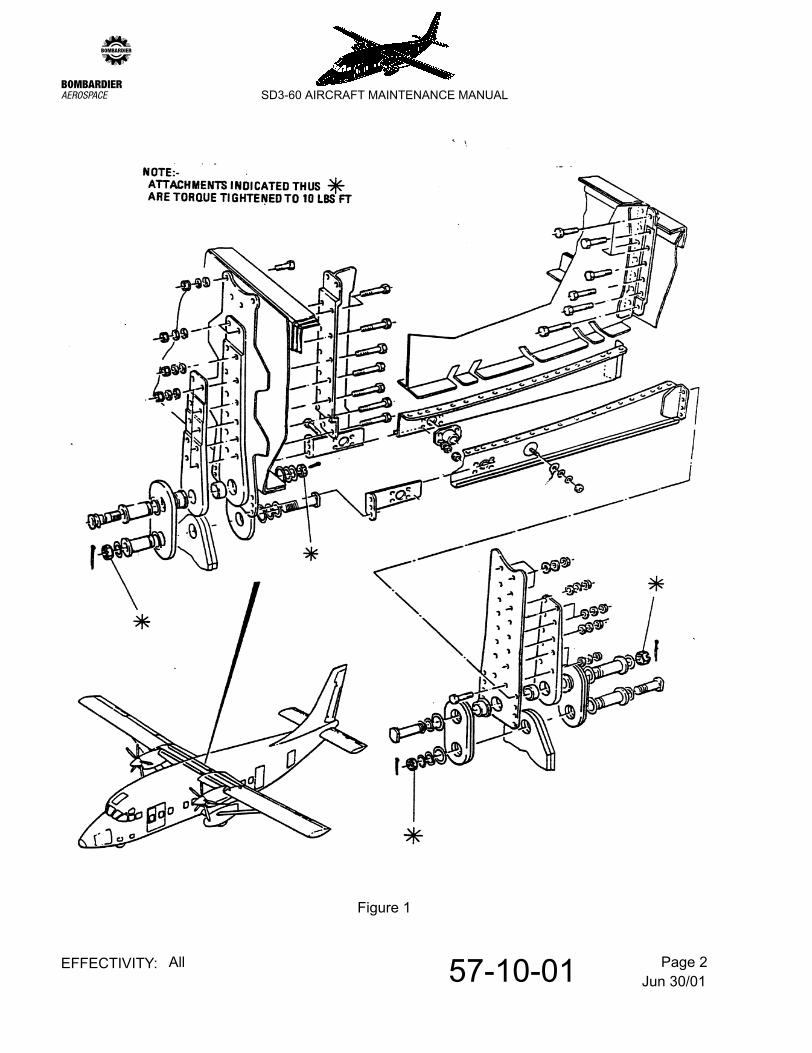
1. General
This section identifys those centre-wing-to fuselage attachment bolts/nuts which are subject to special torque considerations; for details of required torque loading:
- Refer to Figure 1.- Refer to Figure 2.- Refer to Figure 3.
On earlier aircraft, these attachments were painted green for identification purposes; if replaced, employ the current production process of applying witness marks using green putty. Refer to 20-09-06, pb1.
NOTE: Bolts/nuts having red putty witness marks (or red paint on earlier aircraft) are torque controlled to standard values. Refer to 20-09-06, pb1.
Jun 30/0157-10-01 Page 2EFFECTIVITY: All
zSD3-60 AIRCRAFT MAINTENANCE MANUAL
Figure 1
Jun 30/0157-10-01 Page 3EFFECTIVITY: All
zSD3-60 AIRCRAFT MAINTENANCE MANUAL
Figure 2
Jun 30/0157-10-01 Page 4EFFECTIVITY: All
zSD3-60 AIRCRAFT MAINTENANCE MANUAL
Figure 3
Apr 03/1557-40-01 Page 601EFFECTIVITY: All
zSD3-60 AIRCRAFT MAINTENANCE MANUAL
AMM57-40-01 1.0.0.0WING/NACELLE ATTACHMENT LUGS (REAR SPAR) - INSPECTION/CHECK
This inspection procedure must only be performed by a person trained and approved to Personnel Certification in Non-Destructive Testing (PCN) NAS410 or EN4179, level II or level III.
NOTE: This inspection can be performed in conjunction with the following inspections:-Nacelle Attachment Brackets (front spar) - Refer to 54-40-06, pb601.Nacelle Mounting Plates (rear spar) - Refer to 54-40-11, pb601.
The procedure is derived from MW-S360-3-EC. (p spec 300)
1. Applicability
A. Items to be inspected:
2. Purpose:
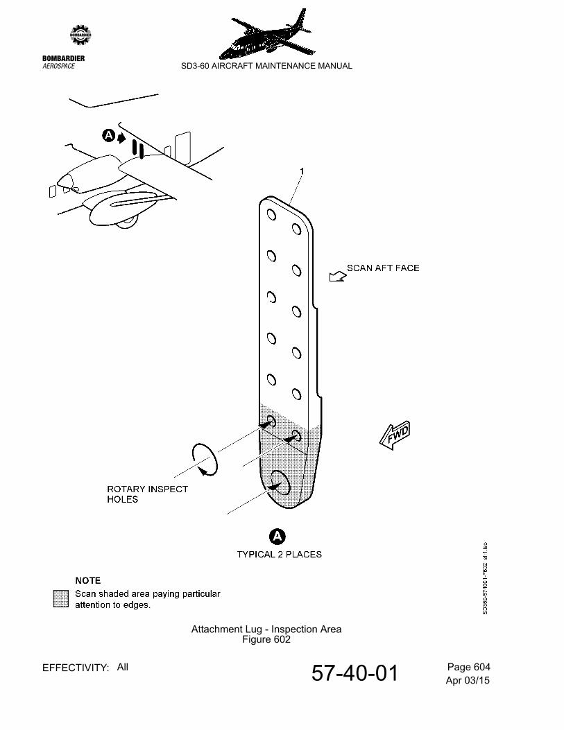
To detect fatigue cracking at the lug holes, the four bolt holes at the rear spar and all accessible surfaces, with particular attention to edges (refer to Figure 602).
Material: 2024 or 2014 Aluminium Alloy
3. Special Tools and Equipment:
Part No: SD3-22-6057xA (LH outer, Pre Mod 7738)SD3-22-6057xB (LH outer, Post Mod 7738)SD3-22-6058xA (RH outer, Pre Mod 7738)SD3-22-6058xB (RH outer, Post Mod 7738)SD3-22-6059xA (LH inner, Pre Mod 7738)SD3-22-6059xB (LH inner, Post Mod 7738)SD3-22-6060xA (RH inner, Pre Mod 7738)SD3-22-6060xB (RH inner, Post Mod 7738)
Portable Eddy Current Flaw Detector: Hocking Locator 2dSemi-shielded Nfe 500 kHz ProbeAL35-45 Calibration Block (SCB)33A103 Rotary Eddy Current Drive UnitRotary Probes, GE Inspection Technologies:-
619P016F051 1/4 Diameter (0.250 in.),619P026F051 13/32 Diameter (0.406 in.) and619P054F051 27/32 Diameter (0.844 in.).
Rotary Calibration Block (with 0.0625 in. holes drilled at 90 degrees to object hole) made from 2024 or 2014 Aluminium Alloy
Apr 03/1557-40-01 Page 602EFFECTIVITY: All
zSD3-60 AIRCRAFT MAINTENANCE MANUAL
NOTE: Equivalent eddy current equipment may be used, provided that it meets the requirements of this procedure. The equipment must be capable of resolving the reference notches in the calibration reference standard at the required level of resolution and sensitivity.
4. Job Set-Up Information For Surface Scan (Refer to Figure 602)
A. Preparation
(1) Render the aircraft electrically safe. Refer to 12-09-03, pb301.
(2) Remove the left nacelle. Refer to 54-10-01, pb401.
(3) Remove access panel 520BT/CT. Refer to 6-30-00, pb1. Figure 9.
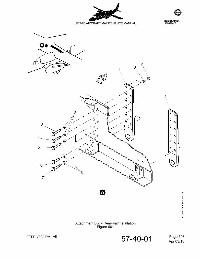
(4) Remove each attachment lug (1) as follows (Refer to Figure. 601):-
NOTE: Make a note of the position of the different attachments for subsequent installation.
(5) Remove the 12 stiffnuts (2), the 12 bolts (3), (4), (5), (6), (7) and the 24 washers (8).
NOTE: Discard the stiffnuts and retain the bolts and washers.
(6) Make sure the attachment lugs are clean and free of chipped or flaking paint.
B. Calibrate the test equipment for surface scan
(1) Portable Eddy Current Flaw Detector:
(a) Set up in accordance with the manufacturer’s instructions.
(b) Connect the probe and obtain a response from the 0.5 mm slot in the SCB.
NOTE: Adjust to give 80% Full Scale Height (FSH).
C. Inspection
Identify the areas to be inspected on the attachment lugs. Refer to Figure 602.
(1) Portable Eddy Current Flaw Detector:
(a) Balance the probe on the component and compensate for lift off effect.
(b) Perform the scan on the area indicated.
5. Job Set-Up Information For Rotary Scan (Refer to Figure 602)
A. Preparation
(1) Ensure that para 4.A. has been completed before continuing.
Apr 03/1557-40-01 Page 603EFFECTIVITY: All
zSD3-60 AIRCRAFT MAINTENANCE MANUAL
Attachment Lug - Removal/InstallationFigure 601
Apr 03/1557-40-01 Page 604EFFECTIVITY: All
zSD3-60 AIRCRAFT MAINTENANCE MANUAL
Attachment Lug - Inspection AreaFigure 602
Apr 03/1557-40-01 Page 605EFFECTIVITY: All
zSD3-60 AIRCRAFT MAINTENANCE MANUAL
B. Portable Eddy Current Flaw Detector Rotary Calibration
(1) Set up in accordance with the manufacturer’s instructions.
(2) Select the time base display and use any of the rotary probes to adjust to give 50% Full Screen Height (FSH) from the 0.0625 in. cross drilled reference bolt.
NOTE: The signal to noise ratio should be 12 dB.
(3) Select spot display and adjust the angular displacement of the reference hole signal to a position 30 degrees anticlockwise of vertical.
NOTE: This signal position is consistent with mechanical damage. A signal that appears more vertical should be considered a defect indication.
C. Rotary Inspection Procedure
(1) Put the probe in the hole and allow the rotational speed to stabilise.
(2) Move the probe slowly down the bore in increments and interpret the signals.
6. Acceptance Criteria
Any discontinuity indication which cannot be attributed to probe handling or geometric effects, is to be considered a defect signal.
7. Reporting Procedure
Record and report all rejections to Bombardier Aerospace:-
Email: [email protected] (preferred), or
Telephone: Customer Response Center (CRC)Local and International 514-855-2999North America only 1-866-JET-1247 (1-866-538-1247) Toll Free
8. Close Out
(1) Put the attachment lugs (1) in position.
(2) Install the 12 retained bolts (7), (6), (5), (4), (3), the 24 retained washers (8) and the 12 new stiffnuts (2) in the positions noted during removal.
(3) Torque tighten the fasteners. Refer to 20-09-06, pb1.
(4) Install access panel 520BT/CT. Refer to 6-30-00, pb1. Figure 9.
(5) Install the left nacelle. Refer to 54-10-01, pb401.
Apr 03/1557-40-01 Page 606EFFECTIVITY: All
zSD3-60 AIRCRAFT MAINTENANCE MANUAL
9. Repeat Procedure
Repeat para 4. thru para 8. inclusive for the right nacelle.
NOTE: Substitute access panel 520BT/CT with 620BT/CT.
Apr 03/1557-40-06 Page 601EFFECTIVITY: All
zSD3-60 AIRCRAFT MAINTENANCE MANUAL
AMM57-40-06 1.0.0.0BOTTOM SHEAR DECK (POST MOD A8662) - INSPECTION/CHECK
This inspection procedure must only be performed by a person trained and approved to Personnel Certification in Non-Destructive Testing (PCN) NAS410 or EN4179, level II or level III.
1. Applicability
A. Item to be inspected:
Bottom forward shear deck SD3-11-6555/6 (LH/RH) and bottom aft shear deck SD3-11-6561/2 (LH/RH).
2. Purpose
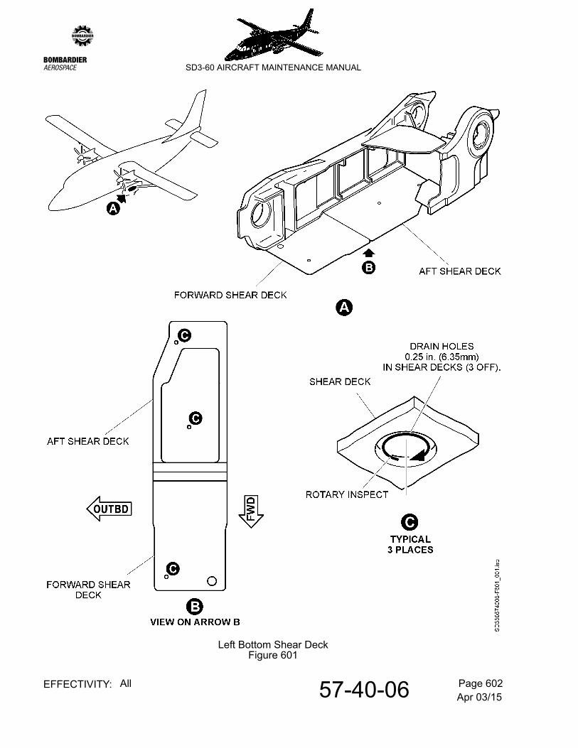
To detect fatigue cracking at all accessible surfaces, with particular attention to drain holes added by mod A8662 (refer to Figure 601).
Material: 7075-T6
3. Special Tools and Equipment
NOTE: Equivalent eddy current equipment may be used, provided that it meets the requirements of this procedure. The equipment must be capable of resolving the reference notches in the calibration reference standard at the required level of resolution and sensitivity.
4. Job Set-Up Information For Surface Scan
Left bottom shear deck.
A. Preparation
(1) Render the aircraft electrically safe. Refer to 12-09-03, pb301.
(2) Remove the main landing gear (MLG) assembly. Refer to 32-10-00, pb201.
(3) Thoroughly steam clean the entire area to remove all debris.
B. Calibrate the test equipment for surface scan
Hocking Locator 2d:
Portable Eddy Current Flaw Detector: Hocking Locator 2dSemi-shielded Nfe 500 kHz ProbeAL35-45 Calibration Block (SCB)33A103 Rotary Eddy Current Drive UnitRotary Probe, GE Inspection Technologies:- 619P016F051 1/4 diameter (0.250 in.)Rotary Calibration Block (with 0.0625 in. holes drilled at 90 degrees to object hole), made from 7075-T7 Aluminium Alloy
Apr 03/1557-40-06 Page 602EFFECTIVITY: All
zSD3-60 AIRCRAFT MAINTENANCE MANUAL
Left Bottom Shear DeckFigure 601
Apr 03/1557-40-06 Page 603EFFECTIVITY: All
zSD3-60 AIRCRAFT MAINTENANCE MANUAL
(1) Set up in accordance with the manufacturer’s instructions.
(2) Connect the probe and obtain a response from the 0.5 mm slot in the SCB.
NOTE: Adjust to give 80% Full Scale Height (FSH).
C. Inspection
Identify the areas of the shear deck to be inspected. Refer to Figure 601.
(1) Balance the probe on the component and compensate for lift off effect.
(2) Perform the scan on the area indicated.
5. Job Set-Up Information For Rotary Scan
Refer to Figure 601.
A. Preparation
(1) Ensure that step 4.A. has been completed before continuing.
B. Calibrate the test equipment for rotary scan
Portable Eddy Current Flaw Detector
(1) Set up in accordance with the manufacturer’s instructions.
(2) Select the time base display and use the 0.25 in. rotary probe to adjust to give 50% Full Screen Height (FSH) from the 0.0625 in. cross drilled reference bolt.
NOTE: The signal to noise ratio should be 12 dB.
(3) Select spot display and adjust the angular displacement of the reference hole signal to a position 30 degrees anticlockwise of vertical.
NOTE: This signal position is consistent with mechanical damage. A signal that appears more vertical should be considered a defect indication.
C. Inspection
(1) Position the probe in a hole and allow the rotational speed to stabilise.
(2) Move the probe slowly down the bore in increments and interpret the signals.
6. Acceptance Criteria
Any discontinuity indication which cannot be attributed to probe handling or geometric effects, is to be considered a defect signal.
Apr 03/1557-40-06 Page 604EFFECTIVITY: All
zSD3-60 AIRCRAFT MAINTENANCE MANUAL
7. Reporting Procedure
Record and report all rejections to Bombardier Aerospace:-
Email: [email protected] (preferred), or
Telephone: Customer Response Center (CRC)Local and International 514-855-2999North America only 1-866-JET-1247 (1-866-538-1247) Toll Free
8. Close Out
(1) Install the MLG assembly. Refer to 32-10-00, pb201.
9. Repeat
(1) Repeat para. 4 thru para. 8 inclusive for the right bottom shear deck.
Jun 30/0157-50-01 Page 401EFFECTIVITY: All
zSD3-60 AIRCRAFT MAINTENANCE MANUAL
AMM57-50-01 8.0.0.0AILERON & TAB - REMOVAL/INSTALLATION
1. General
Removal and installation information relating to the tab and primary surface respectively is given in paras. 2 and 3.
NOTE: Bonding leads freed during removal operations are to be re-attached at a convenient stage during installation in accordance with standard practice. Refer to 20-09-05, pb1.
2. Tab
A. Remove a tab
(1) Remove the split pins, nuts, washers and bolts from control rods at lever arms.
NOTE: For re-installation purposes note that a special bolt Pt. No. SL 115 is used at inboard lever arm. Also note that at outboard lever arm a washer is fitted on the outboard side between control rod end and lug of lever arm.
(2) Remove the split pin, nut and washer from outboard tab hinge.
(3) At inboard end of tab remove fail safe plate by removing two bolts and washers.
(4) Withdraw the tab inboard and remove.
B. Install a tab
(1) Insert the tab into the hinge brackets.
(2) Secure at the outboard hinge with a nut and washer.
(3) Fit fail safe plate using two bolts and washers.
(4) Check the tab for freedom of movement.
(5) Lock the hinge nut with a split pin.
(6) Connect up control rods using correct bolts,washers and nuts. Do not lock attachments.
(7) Rig the tab locally and check travel. Refer to 27-12-00, pb201.
(8) Tighten up nuts at control rod attachments at tab control arms and split pin.
Jun 30/0157-50-01 Page 402EFFECTIVITY: All
zSD3-60 AIRCRAFT MAINTENANCE MANUAL
3. Aileron
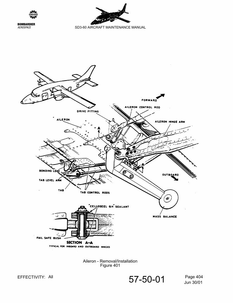
Refer to Figure 401.
A. Remove an aileron
(1) Set the aileron to be removed in its lowest position, release the shrouds and hinge them up or down as applicable.
(2) Release the tab control rods from the tab control arms, remove the split pins, nuts and washers and withdraw the bolts.
(3) Remove split pin, nut and washer and withdraw the bolt from the aileron drive fitting. The drive fitting and control rod will now drop and swing free.
(4) Support the aileron and with reference to section 'AA', proceed as follows:-
(a) Remove the split pin, nuts and washers and withdraw the aileron hinge bolts and fail safe bushes from the inner and outer hinge brackets.
(b) Lift aileron clear.
B. Checks/tests before installation
(1) Before fitting an aileron, ensure that if it has been repaired or painted, it has also been re-balanced. Refer to SRM, 57-60-10.
C. Install an aileron
(1) Clean any residual sealant from attachments.
(2) Offer up the aileron and insert the inner and outer hinge arms into the fork ends of the hinge brackets.
(3) Insert the aileron hinge bolts and fail safe bushes. Secure them with nuts and washers.
(4) Inspect the aileron for freedom of movement.
(5) Check that the aileron control rod is locked in its drive fitting. Locate the drive fitting spigot in the aileron structure, insert the attachment bolt and secure it with a washer and nut.
(6) Offer up the tab control rods into the tab control arms, insert the bolts and secure with washer and nuts.
(7) Rig the control surfaces and tabs locally and carry out function tests as detailed respectively in
- Aileron function check. Refer to 27-11-00, pb201.- Aileron tab function check. Refer to 27-12-00, pb201.
Jun 30/0157-50-01 Page 403EFFECTIVITY: All
zSD3-60 AIRCRAFT MAINTENANCE MANUAL
(8) Lock all the attachments nuts with split pins.
(9) Apply sealant 'CELLOSEEL QH' locally where shown.
Jun 30/0157-50-01 Page 404EFFECTIVITY: All
zSD3-60 AIRCRAFT MAINTENANCE MANUAL
Aileron - Removal/InstallationFigure 401
Jun 30/0157-50-06 Page 401EFFECTIVITY: All
zSD3-60 AIRCRAFT MAINTENANCE MANUAL
AMM57-50-06 9.0.0.0INNER FLAP - REMOVAL/INSTALLATION
1. General
Removal and installation information relating to the inner flap is given in para 2.
NOTE: Bonding leads freed during removal operations are to be re-attached at a convenient stage during installation in accordance with standard practices. Refer to 20-09-05, pb1.
2. Inner flap
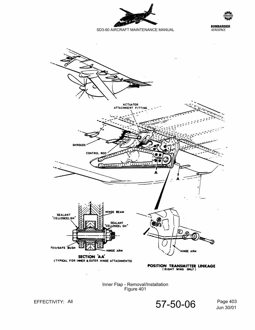
Refer to Figure 401.
A. Remove an inner flap
(1) Set the flaps in their lowest position release the shrouds and hinge upwards to facilitate handling and removal of the inner flap.
(2) Disconnect flap control rod from flap actuator attachment fitting.
(3) Disconnect transmitter linkage rod from the inboard hinge arm(right installation only).
(4) Disconnect damper unit from hinge arm.
(5) Support the flap and with reference to section A-A proceed as follows:-
(a) Disconnect hinge beams from hinge arms.
(b) Lift the flap clear.
B. Install an inner flap
(1) Clean any residual sealant from attachments.
(2) Offer up the flap and insert the inner and outer hinge arms into the fork ends of the hinge beams.
(3) Insert the flap hinge bolts and fail-safe bushes. Secure them with washers and nuts.
(4) Check the flap for freedom of movement.
(5) Insert the flap control rod end into the fork-end of the actuator attachment fitting. Insert the attachment bolt and secure with washer and nut.
(6) Insert the damper end into the fork-end on the hinge arm and insert the attachment bolt and secure with washer and nut.
(7) Attach the position transmitter linkage rod end to the inboard hinge arm (right installation only) using bolt, washers and nut.
Jun 30/0157-50-06 Page 402EFFECTIVITY: All
zSD3-60 AIRCRAFT MAINTENANCE MANUAL
(8) Secure the flap shrouds.
(9) Rig the control surface locally and carry out function test. Refer to 27-51-00, pb201. Adjust the flap-shroud gaps. Refer to 57-00-11, pb201.
(10) Lock all the nuts with split pins.
(11) Apply sealant 'CELLOSEEL QH' locally where shown.
Jun 30/0157-50-06 Page 403EFFECTIVITY: All
zSD3-60 AIRCRAFT MAINTENANCE MANUAL
Inner Flap - Removal/InstallationFigure 401
Jun 30/0157-50-11 Page 401EFFECTIVITY: All
zSD3-60 AIRCRAFT MAINTENANCE MANUAL
AMM57-50-11 10.0.0.0MID FLAP - REMOVAL/INSTALLATION
1. General
Removal and installation information relating to the mid flap is given in para 2.
NOTE: Bonding leads freed during removal operations are to be re-attached at a convenient stage during installation in accordance with standard practice. Refer to 20-09-05, pb1.
2. Mid flap
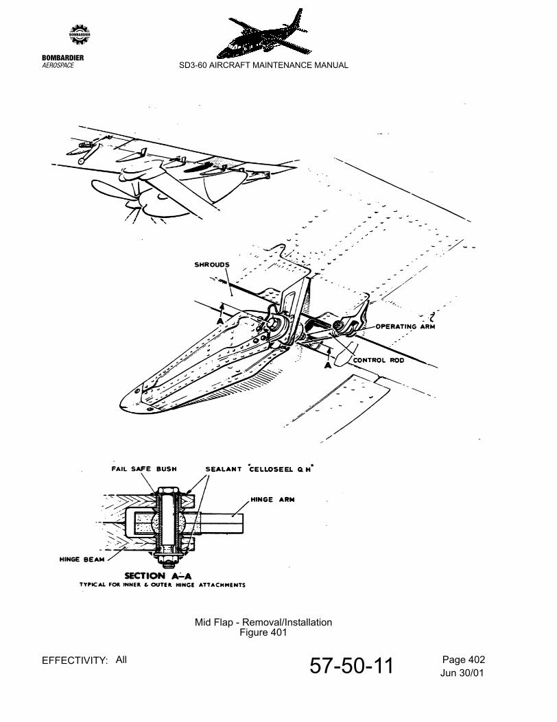
Refer to Figure 401.
A. Remove a mid flap.
(1) Set the flaps in their lowest position, release the shrouds and hinge upwards to facilitate handling and removal of the mid flap.
(2) Disconnect flap control rod from operating arm.
(3) Support the flap and with reference to section A-A proceed as follows:
(a) Disconnect hinge beams from hinge arms.
(b) Lift the flap clear taking care not to damage inter-connecting pin or outer flap.
B. Install a mid flap
(1) Clean any residual sealant from attachments.
(2) Offer up the flap and insert the inner and outer hinge arms into the fork-ends of the hinge beams also making sure that the inter-connecting pin is fitted into appropriate cut-out in outer flap.
(3) Insert the flap hinge bolts and fail safe bushes, then secure with washers and nuts.
(4) Check the flap for freedom of movement.
(5) Insert the flap control rod end into the fork end of the operating arm. Insert the attachment bolt and secure with washer and nut.
(6) Secure the flap shrouds.
(7) Rig the control surface locally and carry out function test. Refer to 27-51-00, pb201. Adjust the flap-shroud gaps. Refer to 57-00-11, pb201.
(8) Lock all nuts with split pins.
(9) Apply sealant 'CELLOSEEL QH' locally where shown.
Jun 30/0157-50-11 Page 402EFFECTIVITY: All
zSD3-60 AIRCRAFT MAINTENANCE MANUAL
Mid Flap - Removal/InstallationFigure 401
Jun 30/0157-50-16 Page 401EFFECTIVITY: All
zSD3-60 AIRCRAFT MAINTENANCE MANUAL
AMM57-50-16 11.0.0.0OUTER FLAP - REMOVAL/INSTALLATION
1. General
Removal and installation information relating to the outer flap is given in para 2.
NOTE: Bonding leads freed during removal operations are to be re-attached at a convenient stage during installation in accordance with standard practice. Refer to 20-09-05, pb1.
2. Outer flap
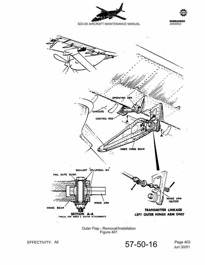
Refer to Figure 401.
A. Remove an outer flap
(1) Set the flaps in their lowest position release the shrouds and hinge upwards to facilitate handling and removal of outer flap.
(2) Disconnect flap control rod from operating arm.
(3) Disconnect transmitter linkage rod from the outboard hinge arm (left installation only).
(4) Support the flap and with reference to section A-A proceed as follows:-
(a) Disconnect hinge beams from hinge arms.
(b) Lift the flap clear taking care not to damage the inter-connecting pin on the mid flap or cut-out in outer flap.
B. Install an outer flap
(1) Clean any residual sealant from attachments.
(2) Offer up the flap and insert the inner and outer hinge arms into the fork ends of the hinge beams also making sure that the inter-connecting pin on the mid flap is fitted into the appropriate cut-out in outer flap.
(3) Insert the flap hinge bolts and fail safe bushes, then secure with washers and nuts.
(4) Check the flap for freedom of movement.
(5) Insert the flap control rod end into the fork-end of the operating arm. Insert the attachment bolt and secure with washer and nut.
(6) Attach the position transmitter linkage rod end to the outboard hinge arm (left installation only) using bolt washers and nut.
(7) Secure the flap shrouds.
Jun 30/0157-50-16 Page 402EFFECTIVITY: All
zSD3-60 AIRCRAFT MAINTENANCE MANUAL
(8) Rig the control surface locally and carry out function test. Refer to 27-51-00, pb201. Adjust the flap-shroud gaps. Refer to 57-00-11, pb201.
(9) Lock all the nuts with split pins.
(10) Apply sealant "CEELOSEEL QH' locally where shown.
Jun 30/0157-50-16 Page 403EFFECTIVITY: All
zSD3-60 AIRCRAFT MAINTENANCE MANUAL
Outer Flap - Removal/InstallationFigure 401