Rhino SD3/XD3 Pneumatic Controls - 1611639-03emanuals.nordson.com/automotive/zfiles/1611639.pdfRhino...
26
Rhino r SD3/XD3 Pneumatic Controls Customer Product Manual Part 1611639−03 Issued 7/18 NORDSON CORPORATION AMHERST, OHIO USA For parts and technical support, call the Industrial Coating Systems Customer Support Center at (800) 433-9319 or contact your local Nordson representative. This document is subject to change without notice. Check http://emanuals.nordson.com for the latest version.
Transcript of Rhino SD3/XD3 Pneumatic Controls - 1611639-03emanuals.nordson.com/automotive/zfiles/1611639.pdfRhino...
Rhino� SD3/XD3 Pneumatic Controls
Customer Product ManualPart 1611639−03
Issued 7/18
NORDSON CORPORATION AMHERST, OHIO USA
For parts and technical support, call the Industrial CoatingSystems Customer Support Center at (800) 433-9319 or
contact your local Nordson representative.
This document is subject to change without notice.Check http://emanuals.nordson.com for the latest version.

Part 1611639−03 � 2018 Nordson Corporation
tents
Table of ContentsSafety 1. . . . . . . . . . . . . . . . . . . . . . . . . . . . . . . . . . . . . . .
Qualified Personnel 1. . . . . . . . . . . . . . . . . . . . . . . . .Intended Use 1. . . . . . . . . . . . . . . . . . . . . . . . . . . . . .Regulations and Approvals 1. . . . . . . . . . . . . . . . . .Personal Safety 2. . . . . . . . . . . . . . . . . . . . . . . . . . . .
High-Pressure Fluids 2. . . . . . . . . . . . . . . . . . . . .Fire Safety 3. . . . . . . . . . . . . . . . . . . . . . . . . . . . . . . .
Halogenated Hydrocarbon Solvent Hazards 4.Action in the Event of a Malfunction 4. . . . . . . . . . .Disposal 4. . . . . . . . . . . . . . . . . . . . . . . . . . . . . . . . . .
Description 5. . . . . . . . . . . . . . . . . . . . . . . . . . . . . . . . . .Operation 7. . . . . . . . . . . . . . . . . . . . . . . . . . . . . . . . . . .
Control Module Symbols and Icons 10. . . . . . . . . . . .Maintenance 11. . . . . . . . . . . . . . . . . . . . . . . . . . . . . . . .
Remove the Control Cover 11. . . . . . . . . . . . . . . . . . .
Parts 12. . . . . . . . . . . . . . . . . . . . . . . . . . . . . . . . . . . . . . .Using the Illustrated Parts List 12. . . . . . . . . . . . . . .Pneumatic Control Module 13. . . . . . . . . . . . . . . . . . .ASD to ACO Conversion Kit 16. . . . . . . . . . . . . . . . . .ACO Connection Kit 16. . . . . . . . . . . . . . . . . . . . . . . . .ACO to ASD Conversion Kit 16. . . . . . . . . . . . . . . . . .Control Valve Service Kits 17. . . . . . . . . . . . . . . . . . . .
Unregulated Air Motor Control Valve Kit 17. . . . .Memory Valve Kit 18. . . . . . . . . . . . . . . . . . . . . . . .Blow-Off Control Valve Kit 19. . . . . . . . . . . . . . . . .Manual Blow-Off Valve Kit 19. . . . . . . . . . . . . . . . .Manual Purge/Reset Valve Kit 20. . . . . . . . . . . . .ACO Control Valve Kit 20. . . . . . . . . . . . . . . . . . . .
Air Preparation Control Assembly 21. . . . . . . . . . . . .
Contact UsNordson Corporation welcomes requests for information, comments, andinquiries about its products. General information about Nordson can befound on the Internet using the following address:http://www.nordson.com.Address all correspondence to:
Nordson CorporationAttn: Customer Service555 Jackson StreetAmherst, OH 44001
NoticeThis is a Nordson Corporation publication which is protected by copyright.Original copyright date 2017. No part of this document may bephotocopied, reproduced, or translated to another language without theprior written consent of Nordson Corporation. The information containedin this publication is subject to change without notice.
Trademarks
Rhino, Nordson, and the Nordson logo are registered trademarks ofNordson Corporation.
All other trademarks are the property of their respective owners.

Change Record i
Part 1611639−03� 2018 Nordson Corporation
Change RecordRevision Date Change
01 7/17 Released.
02 6/18 Updated parts list.
03 7/18 Updated fittings and pneumatic schematics.

Change Recordii
Part 1611639−03 � 2018 Nordson Corporation
Rhino� SD3/XD3 Pneumatic Controls 1
Part 1611639−03� 2018 Nordson Corporation
Rhino� SD3/XD3 Pneumatic Controls
Safety Read and follow these safety instructions. Task- and equipment-specificwarnings, cautions, and instructions are included in equipmentdocumentation where appropriate.
Make sure all equipment documentation, including these instructions, isaccessible to persons operating or servicing equipment.
Qualified Personnel Equipment owners are responsible for making sure that Nordson equipmentis installed, operated, and serviced by qualified personnel. Qualifiedpersonnel are those employees or contractors who are trained to safelyperform their assigned tasks. They are familiar with all relevant safety rulesand regulations and are physically capable of performing their assignedtasks.
Intended Use Use of Nordson equipment in ways other than those described in thedocumentation supplied with the equipment may result in injury to personsor damage to property.
Some examples of unintended use of equipment include
� using incompatible materials
� making unauthorized modifications
� removing or bypassing safety guards or interlocks
� using incompatible or damaged parts
� using unapproved auxiliary equipment
� operating equipment in excess of maximum ratings
Regulations and Approvals Make sure all equipment is rated and approved for the environment in whichit is used. Any approvals obtained for Nordson equipment will be voided ifinstructions for installation, operation, and service are not followed.
Rhino� SD3/XD3 Pneumatic Controls2
Part 1611639−03 � 2018 Nordson Corporation
Personal Safety To prevent injury follow, these instructions.
� Do not operate or service equipment unless you are qualified.
� Do not operate equipment unless safety guards, doors, or covers areintact and automatic interlocks are operating properly. Do not bypass ordisarm any safety devices.
� Keep clear of moving equipment. Before adjusting or servicing movingequipment, shut off the power supply and wait until the equipmentcomes to a complete stop. Lock out power and secure the equipment toprevent unexpected movement.
� Relieve (bleed off) hydraulic and pneumatic pressure before adjusting orservicing pressurized systems or components. Disconnect, lock out,and tag switches before servicing electrical equipment.
� While operating manual spray guns, make sure you are grounded.Wear electrically conductive gloves or a grounding strap connected tothe gun handle or other true earth ground. Do not wear or carry metallicobjects such as jewelry or tools.
� If you receive even a slight electrical shock, shut down all electrical orelectrostatic equipment immediately. Do not restart the equipment untilthe problem has been identified and corrected.
� Obtain and read Safety Data Sheets (SDS) for all materials used.Follow the manufacturer’s instructions for safe handling and use ofmaterials, and use recommended personal protection devices.
� Make sure the spray area is adequately ventilated.
� To prevent injury, be aware of less-obvious dangers in the workplacethat often cannot be completely eliminated, such as hot surfaces, sharpedges, energized electrical circuits, and moving parts that cannot beenclosed or otherwise guarded for practical reasons.
High-Pressure Fluids High-pressure fluids, unless they are safely contained, are extremelyhazardous. Always relieve fluid pressure before adjusting or servicing highpressure equipment. A jet of high-pressure fluid can cut like a knife andcause serious bodily injury, amputation, or death. Fluids penetrating theskin can also cause toxic poisoning.
If you suffer a fluid injection injury, seek medical care immediately. Ifpossible, provide a copy of the SDS for the injected fluid to the health careprovider.

Rhino� SD3/XD3 Pneumatic Controls 3
Part 1611639−03� 2018 Nordson Corporation
The National Spray Equipment Manufacturers Association has created awallet card that you should carry when you are operating high-pressurespray equipment. These cards are supplied with your equipment. Thefollowing is the text of this card:
WARNING: Any injury caused by high pressure liquid can be serious. Ifyou are injured or even suspect an injury:
� Go to an emergency room immediately.
� Tell the doctor that you suspect an injection injury.
� Show him this card
� Tell him what kind of material you were spraying
MEDICAL ALERT—AIRLESS SPRAY WOUNDS: NOTE TO PHYSICIAN
Injection in the skin is a serious traumatic injury. It is important to treat theinjury surgically as soon as possible. Do not delay treatment to researchtoxicity. Toxicity is a concern with some exotic coatings injected directly intothe bloodstream.
Consultation with a plastic surgeon or a reconstructive hand surgeon maybe advisable.
The seriousness of the wound depends on where the injury is on the body,whether the substance hit something on its way in and deflected causingmore damage, and many other variables including skin microflora residingin the paint or gun which are blasted into the wound. If the injected paintcontains acrylic latex and titanium dioxide that damage the tissue’sresistance to infection, bacterial growth will flourish. The treatment thatdoctors recommend for an injection injury to the hand includes immediatedecompression of the closed vascular compartments of the hand to releasethe underlying tissue distended by the injected paint, judicious wounddebridement, and immediate antibiotic treatment.
Fire Safety To avoid a fire or explosion, follow these instructions.
� Ground all conductive equipment. Use only grounded air and fluidhoses. Check equipment and workpiece grounding devices regularly.Resistance to ground must not exceed one megohm.
� Shut down all equipment immediately if you notice static sparking orarcing. Do not restart the equipment until the cause has been identifiedand corrected.
� Do not smoke, weld, grind, or use open flames where flammablematerials are being used or stored.
� Do not heat materials to temperatures above those recommended bythe manufacturer. Make sure heat monitoring and limiting devices areworking properly.
Rhino� SD3/XD3 Pneumatic Controls4
Part 1611639−03 � 2018 Nordson Corporation
Fire Safety (contd)
� Provide adequate ventilation to prevent dangerous concentrations ofvolatile particles or vapors. Refer to local codes or your material SDSfor guidance.
� Do not disconnect live electrical circuits when working with flammablematerials. Shut off power at a disconnect switch first to preventsparking.
� Know where emergency stop buttons, shutoff valves, and fireextinguishers are located. If a fire starts in a spray booth, immediatelyshut off the spray system and exhaust fans.
� Shut off electrostatic power and ground the charging system beforeadjusting, cleaning, or repairing electrostatic equipment.
� Clean, maintain, test, and repair equipment according to the instructionsin your equipment documentation.
� Use only replacement parts that are designed for use with originalequipment. Contact your Nordson representative for parts informationand advice.
Halogenated Hydrocarbon Solvent Hazards Do not use halogenated hydrocarbon solvents in a pressurized system thatcontains aluminum components. Under pressure, these solvents can reactwith aluminum and explode, causing injury, death, or property damage.Halogenated hydrocarbon solvents contain one or more of the followingelements:
Element Symbol Prefix
Fluorine F “Fluoro-”
Chlorine Cl “Chloro-”
Bromine Br “Bromo-”
Iodine I “Iodo-”
Check your material SDS or contact your material supplier for moreinformation. If you must use halogenated hydrocarbon solvents, contactyour Nordson representative for information about compatible Nordsoncomponents.
Action in the Event of a Malfunction If a system or any equipment in a system malfunctions, shut off the systemimmediately and perform the following steps:
� Disconnect and lock out system electrical power. Close hydraulic andpneumatic shutoff valves and relieve pressures.
� Identify the reason for the malfunction and correct it before restarting thesystem.
Disposal Dispose of equipment and materials used in operation and servicingaccording to local codes.

Rhino� SD3/XD3 Pneumatic Controls 5
Part 1611639−03� 2018 Nordson Corporation
Description WARNING: Allow only qualified personnel to perform the following tasks.Follow the safety instructions in this document and all other relateddocumentation.
NOTE: Throughout this manual, the Rhino� pneumatic controls will bereferred to as the control module.
See Figures 1 and 2.
The control module provides the pneumatic operating functions for theunloader. It mounts to the air motor base plate.
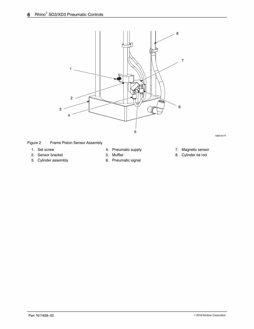
The control module is configured for automatic shutdown (ASD) of the airmotor. The control will shut off the air motor when the piston of the cylinderassembly (3) actuates the magnetic sensor (7) on the frame assembly. Themagnetic sensor is mounted to a bracket (2) that is secured to the cylinderassembly tie rod (8) by a set screw (1). This position of the sensor bracketcan be adjusted to correspond to the position of the follower in the materialdrum at the empty condition. This will allow the control to shut down thepump when the material container is empty, preventing a pump runawaycondition.
Control Module
Unloader
10016501
Figure 1 Rhino Unloader
Rhino� SD3/XD3 Pneumatic Controls6
Part 1611639−03 � 2018 Nordson Corporation
4
6
8
7
3
1
2
510014177
Figure 2 Frame Piston Sensor Assembly
1. Set screw2. Sensor bracket3. Cylinder assembly
4. Pneumatic supply5. Muffler6. Pneumatic signal
7. Magnetic sensor8. Cylinder tie rod

Rhino� SD3/XD3 Pneumatic Controls 7
Part 1611639−03� 2018 Nordson Corporation
Operation Refer to Table 1 and see Figures 3 and 4 for a list of all the control modulecomponents.
NOTE: The Rhino SD3/XD3 assembly is rated for a maximum inputpressure of 7 bar (100 psi).
The control module is fully pneumatic. Shop air pressure is supplied to thecontrol when the control module lockout valve (2) is opened. Opening thislockout valve allows for operation of the elevator control valve (9) and thematerial container blow-off valve (4). Air pressure to the air motorregulator (1), as well as the signal valves in the control and air motor, arealso activated. Air pressure is only supplied to the air motor when the airmotor lockout valve (5) is opened. The air supply to the pilot, intermediate,and material container blow-off valves (4) is at full shop pressure.
The regulated air supply for the elevator cylinder(s) flows to a three-positionelevator control valve (9). The valve controls the flow of air to the elevatorcylinder(s). The elevator control valve has three positions: Ram Up, RamDown, and Neutral.
� Ram Up position: Air enters the bottom of the cylinder(s). Air abovethe elevator cylinder piston(s) is vented. The air pressure forces thecylinder piston(s) upward, which raises the follower plate and pump.
� Ram Down position: Air enters the top of the cylinder(s). Air belowthe elevator cylinder piston(s) is vented. The air pressure forces thecylinder piston(s) downward, which lowers the follower plate andpump.
� Neutral position: There is no pressure to the elevator cylinder(s).The follower plate should remain stationary, since the air pressure toboth sides of the piston(s) is sealed.
WARNING: The Neutral position is not a locked and secured position. Thefollower plate may drift downward over time.
When the piston of the elevator cylinder(s) activates the magnetic sensor atthe bottom of the elevator cylinder(s), the control will shut off air supply tothe air motor, signaling that the material container is empty. Follow theDrum Change Procedure in the Operation section of this manual tocomplete the drum change procedure.
Unregulated air at full shop pressure is supplied to the material containerblow-off valve (4) when the following conditions are achieved:
1. The elevator control valve (9) is in the Ram Up position.
2. The air pressure on the elevator cylinder(s) Ram Up piston is greaterthan the elevator cylinder(s) Ram Down piston by more than 2 psi.
3. The button of the material container blow-off valve (4) is pressed andheld.
NOTE: Air supply to the material container blow-off valve (4) can beachieved with the elevator control valve (9) in the Neutral position ifcondition #2 is satisfied.

Rhino� SD3/XD3 Pneumatic Controls8
Part 1611639−03 � 2018 Nordson Corporation
Operation (contd)
The blow-off feature routes air under the follower plate during the removal ofan empty container. The material container blow-off valve connects to thefollower blow-off port. Pressing and holding the push button on the materialcontainer blow-off valve forces air under the follower plate. The air pressureforces the container off of the follower plate.
Following the drum change procedure and loading of the new materialcontainer, the pneumatic reset valve (7) must be pressed to reset the airmotor’s control valves to begin operation of the air motor.
Table 1 Control Module Components
Item Description
1 Air Motor Regulator: The air motor regulator controls the air to the pump.
2 Control Module Lockout Valve: The control module lockout valve allows the controlmodule to be locked out of receiving input air pressure, necessary to service the unloader.
3 Elevator Air Regulator: The elevator air regulator controls the air to the elevator cylinder.
4
Material Container Blow-Off Valve: The material container blow-off valve activates theflow of the air to the blow-off check valve located on the follower plate. This forces air beneath the bottom of the follower plate and into the container. The pressure forces the follower out of the container.
5 Air Motor Lockout Valve: The air motor lockout valve allows the air motor to be lockedout of receiving air pressure from the control module for service.
6 Air Motor Pressure Gauge: The air motor pressure gauge displays the pressure to theair motor.
7 Pneumatic Reset Valve: The pneumatic reset valve resets the control module’s signalvalves when pressed.
8 Elevator Air Pressure Gauge: The elevator air pressure gauge displays the pressure tothe elevator cylinder.
9
Elevator Control Valve: The elevator control valve initiates ram movement. � Ram Up position raises the elevator and the follower plate. � Ram Down position lowers the elevator and follower plate assembly into the material container. � Neutral position stops elevator movement. Neutral is not a locked and secured position. The follower plate may drift downward over time.

Rhino� SD3/XD3 Pneumatic Controls 9
Part 1611639−03� 2018 Nordson Corporation
9
7
8
1
2
3
4
6
5
10015696
Figure 3 Control Module
1. Air motor regulator2. Control module lockout valve3. Elevator air regulator
4. Material container blow-off valve5. Air motor lockout valve6. Air motor pressure gauge
7. Pneumatic reset valve8. Elevator air pressure gauge9. Elevator control valve
Rhino� SD3/XD3 Pneumatic Controls10
Part 1611639−03 � 2018 Nordson Corporation
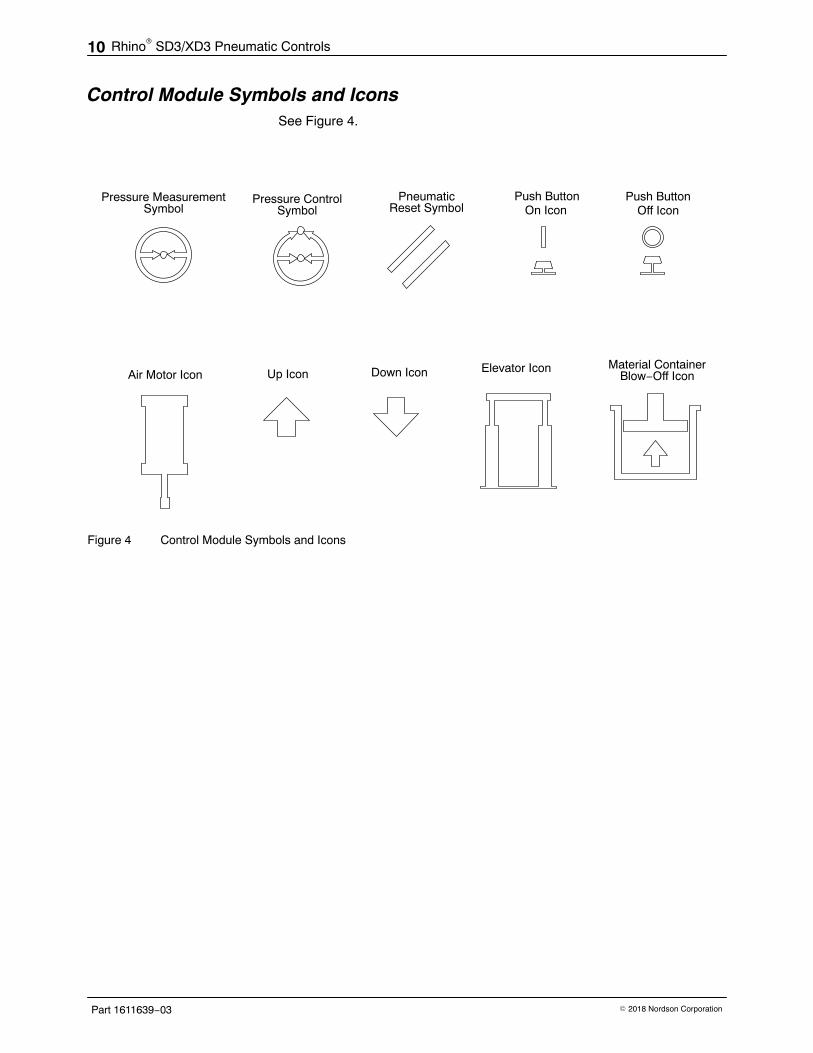
Control Module Symbols and IconsSee Figure 4.
Elevator Icon
Pressure MeasurementSymbol
PneumaticReset Symbol
Material ContainerBlow−Off IconAir Motor Icon
Pressure ControlSymbol
Up Icon Down Icon
Push ButtonOff Icon
Push ButtonOn Icon
Figure 4 Control Module Symbols and Icons

Rhino� SD3/XD3 Pneumatic Controls 11
Part 1611639−03� 2018 Nordson Corporation
Maintenance Refer to the following procedures for valve or gauge replacement.
Remove the Control CoverSee Figure 5.
1. Loosen the regulator nuts (1).
2. Remove the elevator control valve handle (2)
3. Remove the elevator control valve nut (4).
4. Remove the cover (3) from the control module.
1
3
4
2
10015696
Figure 5 Control Module Cover Removal
1. Regulator nut2. Elevator control valve handle
3. Cover 4. Elevator control valve nut

Rhino� SD3/XD3 Pneumatic Controls12
Part 1611639−03 � 2018 Nordson Corporation
Parts To order parts, call the Nordson Industrial Coating Systems CustomerSupport Center at (800) 433-9319 or contact your local Nordsonrepresentative.
Using the Illustrated Parts List Numbers in the Item column correspond to numbers that identify parts inillustrations following each parts list. The code NS (not shown) indicatesthat a listed part is not illustrated. A dash (—) is used when the part numberapplies to all parts in the illustration.
The number in the Part column is the Nordson Corporation part number. Aseries of dashes in this column (−−−−−−) means the part cannot be orderedseparately.
The Description column gives the part name, as well as its dimensions andother characteristics when appropriate. Indentions show the relationshipsbetween assemblies, subassemblies, and parts.
� If you order the assembly, items 1 and 2 will be included.
� If you order item 1, item 2 will be included.
� If you order item 2, you will receive item 2 only.
The number in the Quantity column is the quantity required per unit,assembly, or subassembly. The code AR (As Required) is used if the partnumber is a bulk item ordered in quantities or if the quantity per assemblydepends on the product version or model.
Letters in the Note column refer to notes at the end of each parts list. Notescontain important information about usage and ordering. Special attentionshould be given to notes.
Item Part Description Quantity Note— 0000000 Assembly 11 000000 � Subassembly 2 A2 000000 � � Part 1

Rhino� SD3/XD3 Pneumatic Controls 13
Part 1611639−03� 2018 Nordson Corporation
Pneumatic Control ModuleSee Figure 6 and refer to the following parts list.
10015720
1
UNREGULATED AIR MOTOR
SEE FIGURE 7CONTROL VALVE
ACO CONTROL VALVESEE FIGURE 7
MANUAL PURGE VALVESEE FIGURE 7
7
1
6
98
3
5
10
234
12
11
BLOW-OFF CONTROL VALVESEE FIGURE 7
MEMORY VALVESEE FIGURE 7
1314
19
1718
MANUAL BLOW-OFF VALVESEE FIGURE 7
15
16
PARTIAL REAR VIEW
Figure 6 Control Module, ACO Version Shown

Rhino� SD3/XD3 Pneumatic Controls14
Part 1611639−03 � 2018 Nordson Corporation
10015720
UNREGULATED AIR MOTORCONTROL VALVE
MEMORY VALVE BLOW-OFF CONTROL VALVE
MANUAL BLOW-OFF VALVE MANUAL PURGE/RESET VALVE ACO CONTROL VALVE
20
21
2430
27
24
23
24
24
22
23
25 24
26
24
26
22
24
23
22
32
27 31
29
2822
23
3334BLACK BUTTON
GREEN BUTTON
31
Figure 7 Control Valves

Rhino� SD3/XD3 Pneumatic Controls 15
Part 1611639−03� 2018 Nordson Corporation
Item Part Part Description Qty Note— −−−−−− — CONTROL, module, ACO 1— — −−−−−− CONTROL, module, ASD 11 −−−−−− −−−−−− � SCREW, socket, M3 x 45, Zinc, Class 12.9, per ISO 4762 4 A2 −−−−−− −−−−−− � FITTING, tube, manifold, 2−8-mm x 6x−4-mm 13 326139 326139 � PLUG, blanking, 4-mm T 4 B4 −−−−−− −−−−−− � NUT, nylon, lock, Zinc, M4, per ISO 10511 55 1610177 1610177 � FILTER, inline, assembly, 5 micron, 8-mm T 16 1609441 1609441 � CONTROL, air, preparation, assembly 17 −−−−−− −−−−−− � SCREW, flat, socket, M6 x 14, zinc, Class 12.9, per ISO 10642 48 −−−−−− −−−−−− � SCREW, socket, M5 x 30, zinc, Class 12.9, per ISO 4762 49 1609445 1609445 � VALVE, rotary, 4-port, 3-position 110 −−−−−− −−−−−− � PLATE, mating, control, R73G 1
11 −−−−−− −−−−−− � SCREW, socket head, M4 x 7 x 30, zinc, Class 12.9, per ISO 4762 3
12 −−−−−− −−−−−− � SCREW, socket, cap, M4 x 25, zinc, Class 12.9, per ISO 4762 213 −−−−−− — � LABEL, signal, ACO 114 −−−−−− −−−−−− � LABEL, ram down, pneumatic line 115 −−−−−− −−−−−− � LABEL, empty sensor, pneumatic lines 116 1013412 1013412 � UNION, bulkhead, 4-mm T x 4-mm T 217 — −−−−−− � VALVE, pneumatic, logic, element, 3-port 118 — −−−−−− � SCREW, socket head, M3 x 20, zinc, Class 12.9, per ISO 4762 219 1614026 1614026 � CONNECTOR, bulkhead, 8-mm T x 8-mm T, flame retardant 3 C20 −−−−−− −−−−−− � ELBOW, male, 8-mm tube x R ⅛, flame retardant 221 −−−−−− −−−−−− � ASSEMBLY, valve, air, 3/2, ⅛, normally closed 122 1603927 1603927 � CONNECTOR, male, elbow, 8 mm x R ⅛ 4 A23 1108313 1108313 � MUFFLER, exhaust, R ⅛ 3 D24 1611581 1611581 � ELBOW, male, 4-mm tube x R ⅛ 7 E25 1612202 1612202 � TEE, branch, 4-mm T x R ⅛, brass 126 −−−−−− −−−−−− � ASSEMBLY, valve, air, 3/2, ⅛ 227 1612609 1612609 � MUFFLER, sintered bronze, R ¼ 228 1607282 1607282 � ELBOW, male, 8-mm tube x R ¼ 129 −−−−−− −−−−−− � ASSEMBLY, valve, 3/2, manual, ¼, black 130 −−−−−− −−−−−− � ASSEMBLY, valve, 3/2, manual, ¼ 131 −−−−−− −−−−−− � ELBOW, male, 4-mm T x R ¼, brass 232 −−−−−− — � VALVE, air, 3/2 way, ⅛, normally open 133 −−−−−− — � ELBOW, plug-in, 4-mm T x 8-mm stem, plastic 134 −−−−−− — � TEE, male, 5/6 tube x R ⅛, brass 1NS 900619 900619 � TUBING, polyurethane, 8-mm OD, black ARNS 1097143 1097143 � TUBING, polyurethane, 4-mm OD x 0.79 mm, black ARNS 900464 900464 � ADHESIVE, Loctite� Threadlocker Blue 242�, removable, 50 m ARNS 900481 900481 � ADHESIVE, pipe/threaded/hydraulic sealant AR
NOTE A: ACO version has qty 4; ASD version has qty 2.
B: ACO version has qty 4; ASD version has qty 5.
C: ACO version has qty 3; ASD version has qty 1.
D: ACO version has qty 4; ASD version has qty 3.
E: ACO version has qty 7; ASD version has qty 6.
NS: Not Shown

Rhino� SD3/XD3 Pneumatic Controls16
Part 1611639−03 � 2018 Nordson Corporation
ASD to ACO Conversion KitThe ASD to ACO conversion kit converts an unloader from automaticshutdown (ASD) controls to automatic crossover (ACO) controls.
Part Description Note1610290 KIT, conversion, ASD to ACO control, SD3/XD3
ACO Connection KitThe ACO connection kit contains tubing to connect two ACO-capableunloaders to form a dual-pump system.
Part Description Note1612243 KIT, connection, pneumatic, Rhino, SD3/XD3, ACO
ACO to ASD Conversion KitThe ACO to ASD conversion kit converts an unloader from automaticcrossover (ACO) controls to automatic shutdown (ASD) controls.
Part Description Note1613842 KIT, conversion, ACO to ASD control, SD3/XD3

Rhino� SD3/XD3 Pneumatic Controls 17
Part 1611639−03� 2018 Nordson Corporation
Control Valve Service Kits
Unregulated Air Motor Control Valve KitSee Figure 8 and refer to the following parts list.
3
4
5
1
210016560
Figure 8 Unregulated Air Motor Control Valve Kit
Item Part Description Quantity Note
— 1611686KIT, assembly, valve, control, unregulated, airmotor 1
1 −−−−−− � ELBOW, male, 8-mm tube x R ⅛, flameretardant, white 1
2 −−−−−− � VALVE, air, 3/2-way, ⅛, normally closed 13 −−−−−− � ELBOW, male, 4-mm tube x R ⅛ 14 −−−−−− � MUFFLER, air, R ⅛ 15 −−−−−− � CONNECTOR, male, elbow, 8 mm x R ⅛ 1
NS 900481 � ADHESIVE, pipe/thread/hydraulic sealant 1

Rhino� SD3/XD3 Pneumatic Controls18
Part 1611639−03 � 2018 Nordson Corporation
Control Valve Service Kits(contd)
Memory Valve KitSee Figure 9 and refer to the following parts list.
1(ASD VERSION ONLY)
4
5
3
2
4
4 10016561
Figure 9 Memory Valve Kit
Item Part Description Quantity Note— 1611687 KIT, assembly, valve, memory 11 326139 � PLUG, blanking, 4−mm 12 −−−−−− � TEE, branch, 4-mm T x R ⅛, brass 13 −−−−−− � ASSEMBLY, valve, air, 3/2, ⅛ 14 −−−−−− � ELBOW, male, 4-mm tube x R ⅛ 35 −−−−−− � MUFFLER, air, R ⅛ 1
NS 900481 � ADHESIVE, pipe/thread/hydraulic sealant 1

Rhino� SD3/XD3 Pneumatic Controls 19
Part 1611639−03� 2018 Nordson Corporation
Blow-Off Control Valve KitSee Figure 10 and refer to the following parts list.
3
4
2
11
3 10016562
Figure 10 Blow-Off Control Valve Kit
Item Part Description Quantity Note— 1611688 KIT, assembly, valve, control, blow-off 11 −−−−−− � ELBOW, male, 4-mm tube x R ⅛ 22 −−−−−− � ASSEMBLY, valve, air, 3/2, ⅛ 13 −−−−−− � CONNECTOR, male, elbow, 8 mm x R ⅛ 24 −−−−−− � MUFFLER, air, R ⅛ 1
NS 900481 � ADHESIVE, pipe/thread/hydraulic sealant 1
Manual Blow-Off Valve KitSee Figure 11 and refer to the following parts list.
1
2
3
BLACK BUTTON
10016563
Figure 11 Manual Blow-Off Valve Kit
Item Part Description Quantity Note— 1611689 KIT, assembly, valve, manual, blow-off 11 −−−−−− � ASSEMBLY, valve, 3/2, manual, ¼, black 12 −−−−−− � ELBOW, male, 8-mm T x R ¼ 13 −−−−−− � MUFFLER, filter, R ¼ 1
NS 900481 � ADHESIVE, pipe/thread/hydraulic sealant 1
Rhino� SD3/XD3 Pneumatic Controls20
Part 1611639−03 � 2018 Nordson Corporation
Control Valve Service Kits(contd)
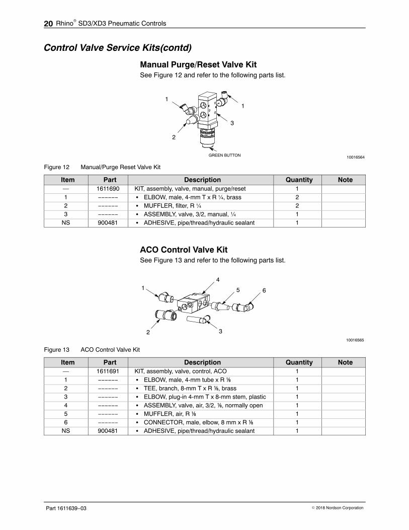
Manual Purge/Reset Valve KitSee Figure 12 and refer to the following parts list.
1
3
2
GREEN BUTTON
1
10016564
Figure 12 Manual/Purge Reset Valve Kit
Item Part Description Quantity Note— 1611690 KIT, assembly, valve, manual, purge/reset 11 −−−−−− � ELBOW, male, 4-mm T x R ¼, brass 22 −−−−−− � MUFFLER, filter, R ¼ 23 −−−−−− � ASSEMBLY, valve, 3/2, manual, ¼ 1
NS 900481 � ADHESIVE, pipe/thread/hydraulic sealant 1
ACO Control Valve KitSee Figure 13 and refer to the following parts list.
65
41
2 310016565
Figure 13 ACO Control Valve Kit
Item Part Description Quantity Note— 1611691 KIT, assembly, valve, control, ACO 11 −−−−−− � ELBOW, male, 4-mm tube x R ⅛ 12 −−−−−− � TEE, branch, 8-mm T x R ⅛, brass 13 −−−−−− � ELBOW, plug-in 4-mm T x 8-mm stem, plastic 14 −−−−−− � ASSEMBLY, valve, air, 3/2, ⅛, normally open 15 −−−−−− � MUFFLER, air, R ⅛ 16 −−−−−− � CONNECTOR, male, elbow, 8 mm x R ⅛ 1
NS 900481 � ADHESIVE, pipe/thread/hydraulic sealant 1

Rhino� SD3/XD3 Pneumatic Controls 21
Part 1611639−03� 2018 Nordson Corporation
Air Preparation Control AssemblySee Figure 14 and refer to the following parts list.
1609441
1
2
1
2
3
3
Figure 14 Air Preparation Control Assembly
Item Part Description Quantity Note— 1609441 CONTROL, air, preparation, assembly 11 1609443 � VALVE, ½ NPT, swing-gate 22 1609442 � REGULATOR, 5−150 psi 23 1610188 � GAUGE, 0−160 psi, ¼ NPT, 50 mm 2

Rhino� SD3/XD3 Pneumatic Controls22
Part 1611639−03 � 2018 Nordson Corporation
This page intentionally left blank.


 WUXI XINJE ELECTRIC CO., ... CPU and expansion devices connection principles, products](https://static.fdocuments.us/doc/165x107/5ab2fcd77f8b9aea528dd685/hardware-xd3xd5xdm-hardware-manualpdfusers-manualhardwarexd3xd5xdm.jpg)