SD3 - UG v1-0 - westmorlandsecurity.co.uk · GSM module installation ... You can either connect the...
35
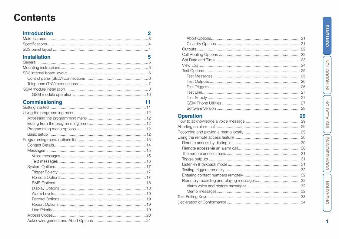
CONTENTS INTRODUCTION INSTALLATION COMMISSIONING OPERATION 1 Contents Introduction 2 Main features .......................................................................................... 3 Specifications ......................................................................................... 4 SD3 panel layout ..................................................................................... 4 Installation 5 General .................................................................................................. 5 Mounting instructions .............................................................................. 5 SD3 internal board layout ....................................................................... 5 Control panel (SELV) connections ........................................................ 6 Telephone (TNV) connections .............................................................. 7 GSM module installation .......................................................................... 8 GSM module operation ................................................................. 10 Commissioning 11 Getting started ..................................................................................... 11 Using the programming menu .............................................................. 12 Accessing the programming menu .................................................... 12 Exiting from the programming menu .................................................. 12 Programming menu options .............................................................. 12 Basic setup ....................................................................................... 12 Programming menu options list ............................................................. 13 Contact Details.................................................................................. 14 Messages ........................................................................................ 15 Voice messages ............................................................................ 15 Text messages .............................................................................. 16 System Options................................................................................. 17 Trigger Polarity .............................................................................. 17 Remote Options ............................................................................ 17 SMS Options................................................................................. 18 Display Options ............................................................................. 18 Alarm Levels.................................................................................. 19 Record Options ............................................................................. 19 Report Options.............................................................................. 19 Line Priority ................................................................................... 19 Access Codes ................................................................................... 20 Acknowledgement and Abort Options .............................................. 21 Abort Options................................................................................ 21 Clear by Options ........................................................................... 21 Outputs ............................................................................................. 22 Call Routing Options ......................................................................... 23 Set Date and Time ............................................................................ 23 View Log ........................................................................................... 24 Test Options ...................................................................................... 25 Test Messages .............................................................................. 25 Test Outputs ................................................................................. 26 Test Triggers .................................................................................. 26 Test Line........................................................................................ 27 Test Supply ................................................................................... 27 GSM Phone Utilities ...................................................................... 27 Software Version ........................................................................... 28 Operation 29 How to acknowledge a voice message ................................................. 29 Aborting an alarm call ............................................................................ 29 Recording and playing a memo locally .................................................. 29 Using the remote access feature ........................................................... 30 Remote access by dialling in ............................................................. 30 Remote access via an alarm call........................................................ 30 The remote access menu .................................................................. 31 Toggle outputs .................................................................................. 31 Listen-in & talkback mode ................................................................. 31 Testing triggers remotely.................................................................... 32 Entering contact numbers remotely ................................................... 32 Remotely recording and playing messages ........................................ 32 Alarm voice and restore messages ................................................ 32 Memo messages........................................................................... 32 Text Editing Keys .................................................................................. 33 Declaration of Conformance .................................................................. 34
-
Upload
truonghuong -
Category
Documents
-
view
217 -
download
1
Transcript of SD3 - UG v1-0 - westmorlandsecurity.co.uk · GSM module installation ... You can either connect the...
CO
NT
EN
TS
INT
RO
DU
CT
ION
INS
TALL
ATIO
NC
OM
MIS
SIO
NIN
GO
PE
RAT
ION
1
ContentsIntroduction 2Main features ..........................................................................................3Specifications .........................................................................................4SD3 panel layout .....................................................................................4
Installation 5General ..................................................................................................5Mounting instructions ..............................................................................5SD3 internal board layout .......................................................................5
Control panel (SELV) connections ........................................................6Telephone (TNV) connections ..............................................................7
GSM module installation ..........................................................................8GSM module operation .................................................................10
Commissioning 11Getting started .....................................................................................11Using the programming menu ..............................................................12
Accessing the programming menu ....................................................12Exiting from the programming menu ..................................................12Programming menu options ..............................................................12Basic setup .......................................................................................12
Programming menu options list .............................................................13Contact Details ..................................................................................14Messages ........................................................................................15
Voice messages ............................................................................15Text messages ..............................................................................16
System Options .................................................................................17Trigger Polarity ..............................................................................17Remote Options ............................................................................17SMS Options .................................................................................18Display Options .............................................................................18Alarm Levels ..................................................................................19Record Options .............................................................................19Report Options ..............................................................................19Line Priority ...................................................................................19
Access Codes ...................................................................................20Acknowledgement and Abort Options ..............................................21
HL
Abort Options ................................................................................21Clear by Options ...........................................................................21
Outputs .............................................................................................22Call Routing Options .........................................................................23Set Date and Time ............................................................................23View Log ...........................................................................................24Test Options ......................................................................................25
Test Messages ..............................................................................25Test Outputs .................................................................................26Test Triggers ..................................................................................26Test Line ........................................................................................27Test Supply ...................................................................................27GSM Phone Utilities ......................................................................27Software Version ...........................................................................28
Operation 29How to acknowledge a voice message .................................................29Aborting an alarm call ............................................................................29Recording and playing a memo locally ..................................................29Using the remote access feature ...........................................................30
Remote access by dialling in .............................................................30Remote access via an alarm call ........................................................30The remote access menu ..................................................................31Toggle outputs ..................................................................................31Listen-in & talkback mode .................................................................31Testing triggers remotely ....................................................................32Entering contact numbers remotely ...................................................32Remotely recording and playing messages ........................................32
Alarm voice and restore messages ................................................32Memo messages ...........................................................................32
Text Editing Keys ..................................................................................33Declaration of Conformance ..................................................................34
CO
NT
EN
TS
INT
RO
DU
CT
ION
INS
TALL
ATIO
NC
OM
MIS
SIO
NIN
GO
PE
RAT
ION
2
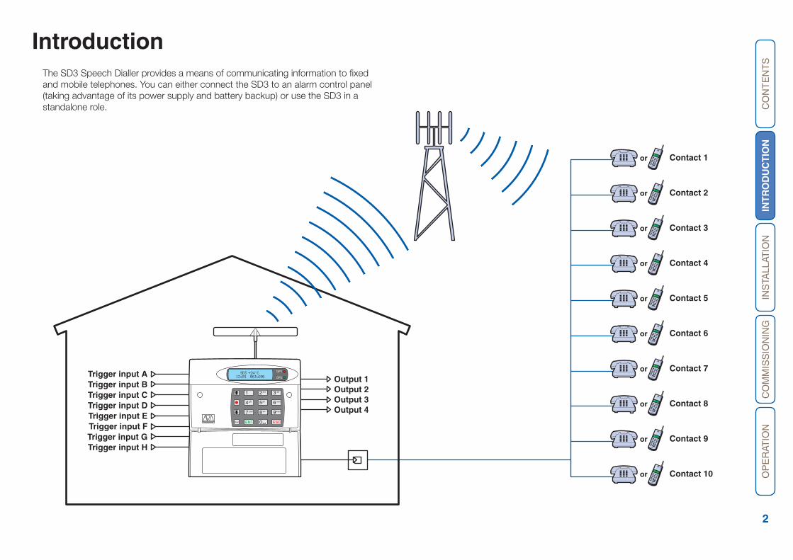
Introduction The SD3 Speech Dialler provides a means of communicating information to fixed and mobile telephones. You can either connect the SD3 to an alarm control panel (taking advantage of its power supply and battery backup) or use the SD3 in a standalone role.
HL
OP1
OP2
3
6
9
ESCENTClear
2
5
8
0
1
4
7
def
mno
wxyz
abc
jkl
tuv
ghi
pqrs
SD3 +24°C12:01 06Jul06Trigger input A
Output 1
Contact 1
Contact 2
Contact 3
Contact 4
Contact 5
Contact 6
Contact 7
Contact 8
Contact 9
Contact 10
or
or
or
or
or
or
or
or
or
or
Output 2Output 3Output 4
Trigger input BTrigger input CTrigger input DTrigger input ETrigger input FTrigger input GTrigger input H
CO
NT
EN
TS
INT
RO
DU
CT
ION
INS
TALL
ATIO
NC
OM
MIS
SIO
NIN
GO
PE
RAT
ION
3
Main features Triggers
The SD3 has eight trigger inputs and you can assign a voice message and/or a text message to each input. The unit can also send a voice message and/or a text message when the triggers have been restored.
For most applications you would normally connect the trigger inputs to the com-municator outputs (or bell output) of an alarm control panel. However, you can also connect other devices, such as smoke detectors or temperature sensors directly to the trigger inputs. The unit allows you to program the polarity of the trigger inputs as either positive or negative applied/removed.
ContactsThe SD3 allows you to store up to 10 contacts: you can assign each one a name, telephone number, message type, and acknowledgement type.
IMPORTANT: DO NOT use the SD3 to call the Police via the emergency services phone numbers.
Voice MessagesThe SD3 has a built-in microphone and speaker to allow you to record and replay audio messages directly from the unit.
The SD3 can store up to eight separate alarm messages, eight restore alarm mes-sages (a different message can be sent when the trigger event has been removed) and one common message (normally used to store the name and address of the premises). Each message can be up to 30 seconds in length.
Text MessagesThe SD3 can also send text messages to mobile telephones using the SMS text service (Short Message Service). The unit does this by calling a SMS service cen-tre, which takes the text message from the SD3 and forwards it to the contact’s mobile telephone. The unit can store eight separate 40-character alarm messages, eight 40-character restore alarm messages (a different message can be sent when the trigger event has been removed) and one common message (normally used to store the name and address of the premises). When the unit sends a text mes-sage, it adds the alarm message to the site details message.
AcknowledgementOn receiving a voice message call from the SD3, the contacted person can ac-knowledge it at any time by pressing 8 on their telephone. If the contact does not acknowledge the voice message then the SD3 repeats the message several times, after which the unit abandons the call and dials the next available contact.
Call-AbortThe SD3 has several call-abort options, which include restoring the trigger input or entering the user code. When the unit has aborted a call it immediately shuts down and returns to its normal standby mode.
OutputsThe SD3 has four programmable outputs that you can use to indicate the status of the unit. You may also program the outputs for remote control. For example, you could use this facility to remotely turn outputs on and off with a touch-tone telephone.
Temperature sensorThe SD3 displays the current ambient temperature. You can program temperature high and low alarms, linking them to two corresponding output types.
Time and dateThe unit contains an internal clock which can display the current time and date. In addition, the time and date will be added to text messages and trigger events, thus providing a useful audit trial in the log.
Please note that the time and date feature is designed as a guide.
Listen-In ModeThe SD3 has a listen-in mode, which switches an internal microphone to the tel-ephone line so that you can hear activity at the protected site.
The contact can activate the listen-in mode at the time of receiving a voice mes-sage or by calling into the SD3 and using the Remote Access feature.
Talkback ModeThe SD3 has a talkback mode, which switches the internal loudspeaker to the tel-ephone line so that you can talk to the protected site. The contact can activate the talkback mode at the time of receiving a voice message or by calling into the SD3 and using the Remote Access feature.
MessageThe SD3 allows you to record short audio messages, either locally at the unit, or remotely, using a touch-tone telephone. After recording a new message the unit will indicate it on the display and can optionally give a beep. You can also program the message feature to record when a trigger input is activated.
Remote AccessIf you enable this feature you can access the SD3 remotely by dialling into the unit with a touch-tone telephone. Once connected you can turn on and off the four outputs, activate the listen-in/talkback mode, listen to the message, record a new message, leave a memo, carry out test triggers or record telephone numbers.
CO
NT
EN
TS
INT
RO
DU
CT
ION
INS
TALL
ATIO
NC
OM
MIS
SIO
NIN
GO
PE
RAT
ION
4
Specifications Supply voltage: 10.5 - 28VDC
Current consumption (@12VDC): 50mA (Standby), 170mA (Active)
Trigger Inputs: Eight: positive/negative applied or positive/negative removed (5 - 24VDC)
Outputs: X4 Open collector switched -ve @100mA
Telecommunications Approval: CTR21
REN Rating: 1
Dialling Formats: DTMF
Dimensions: 140mm x 115mm x 30mm
Weight: 360g (approximately)
Operating environment: -10oC to +55oC
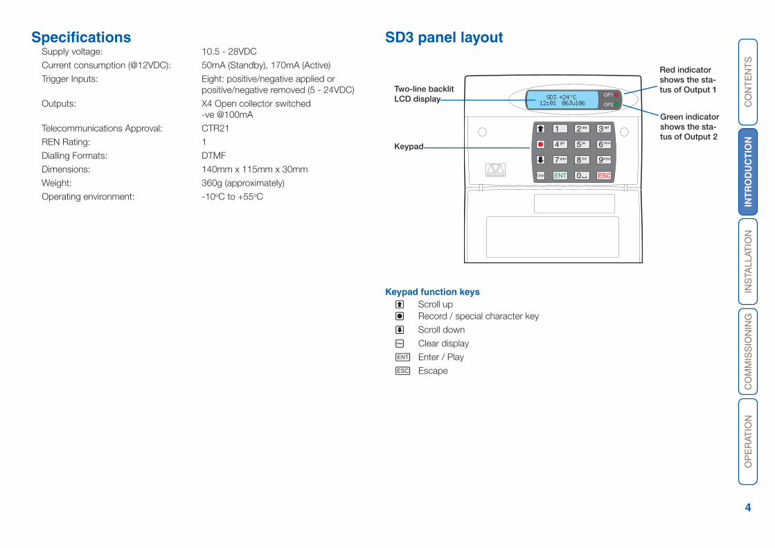
SD3 panel layout
Keypad function keysA Scroll upB Record / special character key
C Scroll down
D Clear display
E Enter / Play
F Escape
OP1
OP2
3
6
9
ESCENTClear
2
5
8
0
1
4
7
def
mno
wxyz
abc
jkl
tuv
ghi
pqrs
SD3 +24°C12:01 06Jul06
Two-line backlit LCD display
Keypad
Red indicator shows the sta-tus of Output 1
Green indicator shows the sta-tus of Output 2

CO
NT
EN
TS
INT
RO
DU
CT
ION
INS
TAL
LA
TIO
NC
OM
MIS
SIO
NIN
GO
PE
RAT
ION
5
Installation
General The SD3 is designed to connect to an intruder alarm control panel or similar.
The SD3 requires a power input (from an alarm control panel or separate power supply) of between 10.5V and 28V, with a supply capability of 100mA or greater.
The SD3 is supplied with a 2-metre telephone lead, which plugs directly into any standard BT socket. Cooper Security recommends that you site the unit as near to a BT telephone socket as possible. If this it not possible you should either obtain an approved BT extension lead or permanently wire the unit to the BT socket (see ‘Connections to the telephone line’).
Mounting instructions1 Separate the cover from the base by using a screwdriver to carefully push two of
the retaining clips (top or bottom) inwards from the base indents.
2 Remove the cover assembly and store in a safe place.
3 Hold the base in position (keyhole to the top) and mark the three securing holes. Remove the base then drill and plug the holes.
4 Pass all cables into the base through the cable entries and then secure the base to wall.
HL
SD3 internal board layout
Connection types and standardsThe SD3 connection terminals contain a mixture of alarm system-related connec-tions and telecommunication connections. The alarm-type connections are termed Safety Extra Low Voltage or SELV, while the telecommunication connections are called Telecommunications Network Voltage or TNV.
Note: It is vitally important that the two types of connections are kept separate and only linked to appropriate external alarm systems and telephone connections, respectively.
TNV circuits should only be connected by a qualified person in accordance with local regulations.
GE
A
A
HF
B
B
C
A1
D
B1
12V0V
OP1
TAM
PERO
P2O
P3O
P4TR
IGTR
IGTR
IG
IN0V
OU
TLI
NE
MicrophoneUpper connector for input triggers and tamper wiring
Lower connector for input triggers, power supply, and output wiring
GSM module sockets
Line connector
Back tamper switch
Sounder/loudspeaker
Telephone line connector
CO
NT
EN
TS
INT
RO
DU
CT
ION
INS
TAL
LA
TIO
NC
OM
MIS
SIO
NIN
GO
PE
RAT
ION
6
Control panel (SELV) connectionsBefore making any connection to the SD3 isolate ALL power from the control panel (mains and battery). Do not continue if there is power still present on the control panel.
+12V & 0V Connect these terminals to the 12V auxiliary power supply of the alarm control panel or to a stand-alone power supply, if necessary.
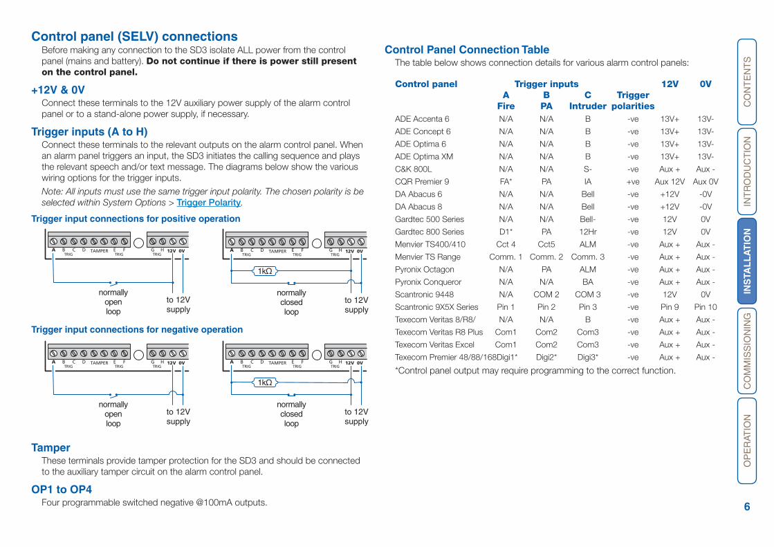
Trigger inputs (A to H) Connect these terminals to the relevant outputs on the alarm control panel. When an alarm panel triggers an input, the SD3 initiates the calling sequence and plays the relevant speech and/or text message. The diagrams below show the various wiring options for the trigger inputs.
Note: All inputs must use the same trigger input polarity. The chosen polarity is be selected within System Options > Trigger Polarity.
Trigger input connections for positive operation
Trigger input connections for negative operation
TamperThese terminals provide tamper protection for the SD3 and should be connected to the auxiliary tamper circuit on the alarm control panel.
OP1 to OP4 Four programmable switched negative @100mA outputs.
Control Panel Connection TableThe table below shows connection details for various alarm control panels:
Control panel Trigger inputs 12V 0V A B C Trigger Fire PA Intruder polaritiesADE Accenta 6 N/A N/A B -ve 13V+ 13V-
ADE Concept 6 N/A N/A B -ve 13V+ 13V-
ADE Optima 6 N/A N/A B -ve 13V+ 13V-
ADE Optima XM N/A N/A B -ve 13V+ 13V-
C&K 800L N/A N/A S- -ve Aux + Aux -
CQR Premier 9 FA* PA IA +ve Aux 12V Aux 0V
DA Abacus 6 N/A N/A Bell -ve +12V -0V
DA Abacus 8 N/A N/A Bell -ve +12V -0V
Gardtec 500 Series N/A N/A Bell- -ve 12V 0V
Gardtec 800 Series D1* PA 12Hr -ve 12V 0V
Menvier TS400/410 Cct 4 Cct5 ALM -ve Aux + Aux -
Menvier TS Range Comm. 1 Comm. 2 Comm. 3 -ve Aux + Aux -
Pyronix Octagon N/A PA ALM -ve Aux + Aux -
Pyronix Conqueror N/A N/A BA -ve Aux + Aux -
Scantronic 9448 N/A COM 2 COM 3 -ve 12V 0V
Scantronic 9X5X Series Pin 1 Pin 2 Pin 3 -ve Pin 9 Pin 10
Texecom Veritas 8/R8/ N/A N/A B -ve Aux + Aux -
Texecom Veritas R8 Plus Com1 Com2 Com3 -ve Aux + Aux -
Texecom Veritas Excel Com1 Com2 Com3 -ve Aux + Aux -
Texecom Premier 48/88/168 Digi1* Digi2* Digi3* -ve Aux + Aux -
*Control panel output may require programming to the correct function.
GEA HFB C D 12V 0VTAMPERTRIGTRIGTRIG
to 12Vsupply
normallyopenloop
GEA HFB C D 12V 0VTAMPERTRIGTRIGTRIG
to 12Vsupply
normallyclosedloop
1kΩ
GEA HFB C D 12V 0VTAMPERTRIGTRIGTRIG
to 12Vsupply
normallyopenloop
GEA HFB C D 12V 0VTAMPERTRIGTRIGTRIG
to 12Vsupply
normallyclosedloop
1kΩ
CO
NT
EN
TS
INT
RO
DU
CT
ION
INS
TAL
LA
TIO
NC
OM
MIS
SIO
NIN
GO
PE
RAT
ION
7
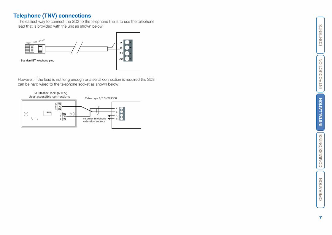
Telephone (TNV) connectionsThe easiest way to connect the SD3 to the telephone line is to use the telephone lead that is provided with the unit as shown below:
321
654 A
B
A1B1
Cable type 1/0.5 CW1308
BT Master Jack (NTE5)User accessible connections
To other telephoneextension sockets
However, if the lead is not long enough or a serial connection is required the SD3 can be hard wired to the telephone socket as shown below:
CO
NT
EN
TS
INT
RO
DU
CT
ION
INS
TAL
LA
TIO
NC
OM
MIS
SIO
NIN
GO
PE
RAT
ION
8
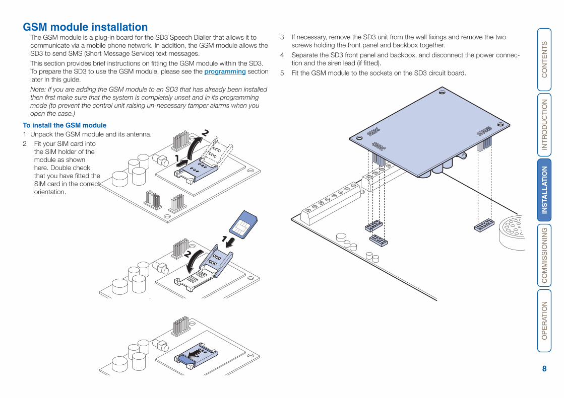
GSM module installationThe GSM module is a plug-in board for the SD3 Speech Dialler that allows it to communicate via a mobile phone network. In addition, the GSM module allows the SD3 to send SMS (Short Message Service) text messages.
This section provides brief instructions on fitting the GSM module within the SD3. To prepare the SD3 to use the GSM module, please see the programming section later in this guide.
Note: If you are adding the GSM module to an SD3 that has already been installed then first make sure that the system is completely unset and in its programming mode (to prevent the control unit raising un-necessary tamper alarms when you open the case.)
To install the GSM module1 Unpack the GSM module and its antenna.
3 If necessary, remove the SD3 unit from the wall fixings and remove the two screws holding the front panel and backbox together.
4 Separate the SD3 front panel and backbox, and disconnect the power connec-tion and the siren lead (if fitted).
5 Fit the GSM module to the sockets on the SD3 circuit board.
2
1
1
2
2 Fit your SIM card into the SIM holder of the module as shown here. Double check that you have fitted the SIM card in the correct orientation.

CO
NT
EN
TS
INT
RO
DU
CT
ION
INS
TAL
LA
TIO
NC
OM
MIS
SIO
NIN
GO
PE
RAT
ION
9
6 Thread the antenna cable through the backbox and connect it to the antenna input socket on the GSM module.
7 Feed the antenna cable around the top and side of the module. Take care not to unseat the antenna connector from the socket as you route the cable.
8 Using the supplied surface wipe, clean the area onto which you intend to stick the antenna.
9 Remove the backing paper on the glued side of the antenna. Fix the antenna onto the cleaned surface. Note: The adhesive on the antenna is fast acting. You will not be able to reposition the antenna once you have put it in place.
10 Re-connect all previously removed connections (including power).
11 Re-attach the SD3 panel onto the backbox and refit the two screws holding the case together.
12 Re-attach the combined unit to the wall fittings.
CO
NT
EN
TS
INT
RO
DU
CT
ION
INS
TAL
LA
TIO
NC
OM
MIS
SIO
NIN
GO
PE
RAT
ION
10
GSM module operationTo use GSM module features1 Apply power to the SD3 unit.
2 From standby, enter the user code, then use the scroll keys (A or C) or 0 to display the Test Options menu:
Test Options
Press E to select. The screen will show the first option: Test Messages.
3 Press C or press 6 to show: GSM Phone Utils.
4 Press E to select. The screen will show the first option: Make Call.
5 Use the scroll keys (A or C) and then E, to select the following options:
Make Call Allows you to enter a number and make a call via the GSM link. The SD3 will act like a hands free mobile phone.
Signal Strength If the level is low you may need to reposition the con-trol unit, or seek another service provider.
GSM Number (This may not appear if you are using Vodafone as a service provider.) Note this number down so that you can supply it when registering your SIM card.
IMEI Number You should note this number down as you will need to provide it when you register your SIM card with certain service providers.
To register your SIM cardOnce you have fitted the GSM module and its SIM card, you must register the SIM card with the service provider. To do this you must make a telephone call from the SD3 control unit via the newly installed GSM module.
1 Using the method discussed above, select the Make Call option.
3 Dial the appropriate telephone number for registering the SIM card as shown in the instruction leaflets for the card. (See below.)
Note that the SD3 cannot support the text message response service calls using the * and # keys. You must call the service provider manually and either register with a human operator, or navigate an automated answering service. Once the phone call is established you can use the * and # keys as you would on a normal phone.
The exact details of registering your SIM card differ for each provider. The follow-ing sections show hints for the main providers.
O2Note that 02 print the SIM serial number and the GSM telephone number on the packing for the SIM card.To register an 02 SIM dial 248 and follow the instructions given by the automatic answering service.
T-MobileT-Mobile print the GSM telephone number, PIN number and PUK (unlock number) on the sheet carrying the SIM card and top up card.To register a T-Mobile SIM dial 150 and follow the instructions given by the auto-matic answering service.If you have several mobile phones fix the sticky label provided showing the GSM number to the top up card.
OrangeMake sure you have the GSM module’s IMEI number to hand. You will also need the SIM card serial number which is printed on the SIM card.You will need to provide a password and the four digit code to identify yourself in the future. Choose them before making the call and write them down in the booklet.To register an Orange SIM dial 0800 079 0006. A human operator will reply.While registering your SIM, the operator will provide you with your GSM number. Make sure you note this number on the top up card.
VodafoneTo register a Vodafone SIM dial 2345 and follow the instructions given by the automatic answering service. During the instructions you will be given your GSM number. Make sure that you note this number down on the back of the top up card.
Using top up cardsEach of the service providers listed in the previous instructions supply top up cards with their SIMs. Part of the registration procedure is to link the top up card with the SIM. The cards contain just enough credit to allow you to make the registration call. Once you have finished this process you will need to supply more credit to the top up card. You should do this immediately.While registering, make sure that you write the phone number of the GSM module down on the top up card.The table below provides spaces for you record the relevant information about your GSM installation.
IMEI No. .....................................................................................
SIM Card Serial No. ....................................................................
GSM No. ....................................................................................
Top Up Card No. ........................................................................
CO
NT
EN
TS
INT
RO
DU
CT
ION
INS
TALL
ATIO
NC
OM
MIS
SIO
NIN
GO
PE
RAT
ION
11
CommissioningOnce all necessary connections have been made to the SD3 speech dialler, clip the cover on to the base, taking care not to trap any cables.
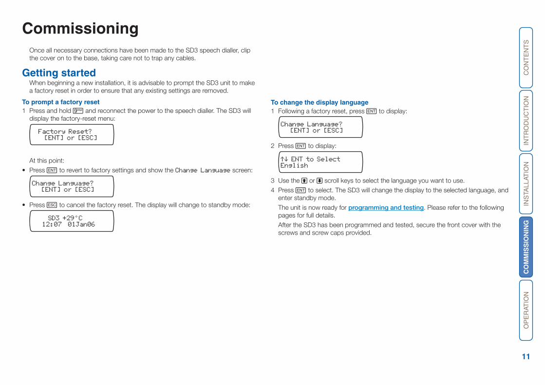
Getting started When beginning a new installation, it is advisable to prompt the SD3 unit to make a factory reset in order to ensure that any existing settings are removed.
To prompt a factory reset1 Press and hold 9 and reconnect the power to the speech dialler. The SD3 will
display the factory-reset menu:
Factory Reset?[ENT] or [ESC]
At this point:
• Press E to revert to factory settings and show the Change Language screen:
Change Language?[ENT] or [ESC]
• Press F to cancel the factory reset. The display will change to standby mode:
SD3 +29°C12:07 01Jan06
To change the display language1 Following a factory reset, press E to display:
Change Language?[ENT] or [ESC]
2 Press E to display:
English
3 Use the A or C scroll keys to select the language you want to use.
4 Press E to select. The SD3 will change the display to the selected language, and enter standby mode.
The unit is now ready for programming and testing. Please refer to the following pages for full details.
After the SD3 has been programmed and tested, secure the front cover with the screws and screw caps provided.
CO
NT
EN
TS
INT
RO
DU
CT
ION
INS
TALL
ATIO
NC
OM
MIS
SIO
NIN
GO
PE
RAT
ION
12
Using the programming menu The programming menu allows you to configure most aspects of SD3 operation and perform a series of tests to either: confirm correct operation, or assist with troubleshooting.
Accessing the programming menuWhen the SD3 is in standby mode the display shows the temperature, time and date, for example:
SD3 +29°C12:07 01Jan06
To access the programming menu1 From standby, enter the user code (the default code is 1234). When the correct
code is entered, the bottom line of the display will show the first item from a menu of ten programming options:
Contact Details
You can scroll up and down through the programming menu by using the scroll keys (A or C), or jump directly to an option by pressing the relevant hot key. For example, to display the log option press 9.
The opposite page shows a list of all ten programming options and their hotkeys.
Exiting from the programming menuWhen using the programming menu, the SD3’s trigger inputs are disabled and therefore the unit will not call out in the event of an alarm.
Note: Please note for correct operation it is necessary to exit the programming in the manner described below.
To exit from the programming menu1 From within the programming menu, press F repeatedly until the display shows:
To Leave MenusPress [ENT]
2 Press E to leave the programming menu and return to standby. Alternatively, if you wish to remain within the programming menu, press E.
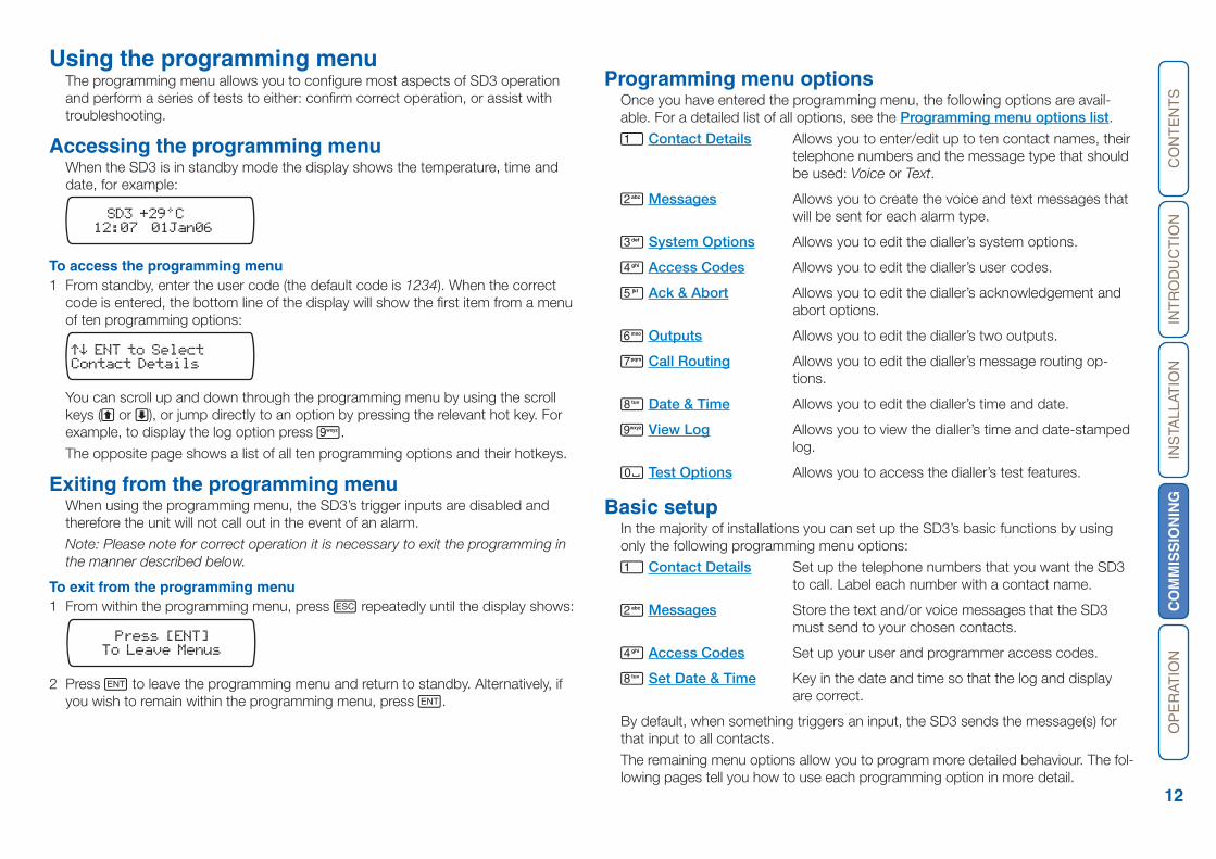
Programming menu optionsOnce you have entered the programming menu, the following options are avail-able. For a detailed list of all options, see the Programming menu options list.
1 Contact Details Allows you to enter/edit up to ten contact names, their telephone numbers and the message type that should be used: Voice or Text.
2 Messages Allows you to create the voice and text messages that will be sent for each alarm type.
3 System Options Allows you to edit the dialler’s system options.
4 Access Codes Allows you to edit the dialler’s user codes.
5 Ack & Abort Allows you to edit the dialler’s acknowledgement and abort options.
6 Outputs Allows you to edit the dialler’s two outputs.
7 Call Routing Allows you to edit the dialler’s message routing op-tions.
8 Date & Time Allows you to edit the dialler’s time and date.
9 View Log Allows you to view the dialler’s time and date-stamped log.
0 Test Options Allows you to access the dialler’s test features.
Basic setupIn the majority of installations you can set up the SD3’s basic functions by using only the following programming menu options:
1 Contact Details Set up the telephone numbers that you want the SD3 to call. Label each number with a contact name.
2 Messages Store the text and/or voice messages that the SD3 must send to your chosen contacts.
4 Access Codes Set up your user and programmer access codes.
8 Set Date & Time Key in the date and time so that the log and display are correct.
By default, when something triggers an input, the SD3 sends the message(s) for that input to all contacts.
The remaining menu options allow you to program more detailed behaviour. The fol-lowing pages tell you how to use each programming option in more detail.

CO
NT
EN
TS
INT
RO
DU
CT
ION
INS
TALL
ATIO
NC
OM
MIS
SIO
NIN
GO
PE
RAT
ION
13
Programming menu options list4 Display Options
1 Flash on Message2 Beep on Message3 Temp Display4 Line Fault
5 Alarm Levels1 Temperature High2 Temperature Low3 Supply Low4 Signal Low
6 Record Options1 Long Play2 Auto Record
7 Report Options1 Auto Reporting2 Report Time
8 Line Priority1 PSTN Only2 GSM Only3 PSTN first4 GSM first
4 Access Codes
1 Edit User Code2 Edit Remote Code
5 Ack & Abort
1 Abort OptionsNonePasscode OnlyCode or RestoreRestore Only
2 Clear by OptionsAnyoneNo One
6 Outputs
Output 1OFFMessage WaitingRemote AccessTemperature HighTemperature LowListen Active Speech ActivePhone Line FaultPSTN In UseGSM In UseCall ActiveCall SuccessfulCall FailedRemote Control 1Remote Control 2Remote Control 3Remote Control 4Supply Volts LowGSM Signal Low
Output 2 as for Output 1Output 3 as for Output 1Output 4 as for Output 1
7 Call Routing
1 Trigger AlarmRoute A Alarm ToRoute B Alarm To…Route H Alarm To
2 Trigger RestoreRoute A Restore ToRoute B Restore To…Route H Restore To
3 Auto ReportRoute Auto Rep. To
8 Date & Time
Enter New DateEnter New Time
9 View Log
(A for newer, C for older)
0 Test Options
1 Test MessagesSend Alarm A To… Send Alarm H ToSend Restore A To… Send Restore H To
2 Test Outputs(press 1 to 4 to activate outputs)3 Test Triggers(activate each input in turn)4 Test Line5 Test Supply6 GSM Phone Utils
1 Make Call2 Signal Strength3 GSM Number4 IMEI Number5 IMSI Number6 Module Type7 Call Provider
7 Software Version
1 Contact Details
1 Contact 01 Name 2 Contact 02 Name … 0 Contact 10 Name
2 Messages
1 Voice Message 1 Voice Alarm A …8 Voice Alarm H9 Voice Restore A … Voice Restore H Voice Site
2 Text Message1 Text Alarm A …8 Text Alarm H9 Text Restore A … Text Restore H Text Site
3 System Options
1 Trigger Polarity1 Negative2 Positive
2 Remote Options1 Remote Access2 Rings to Answer3 1 Ring Answer
3 SMS Options1 SMS Call Number2 SMS Format3 SMS Protocol4 SD3 Tel. Number

CO
NT
EN
TS
INT
RO
DU
CT
ION
INS
TALL
ATIO
NC
OM
MIS
SIO
NIN
GO
PE
RAT
ION
14
Contact DetailsThe SD3 can store up to 10 contacts; each contact is assigned the following parameters:
NameUp to 16 characters can be assigned to the contact name.
Telephone No.Each contact’s telephone number can have up to 24 digits. When programming the contact’s telephone number the B key can be used to insert the following command characters:
* Star: Inserts a * into the telephone number.
# Hash: Inserts a # in the telephone number.
, Pause: If the unit is connected to an internal telephone system you normally have to dial a number to get an external line, wait a couple of seconds, then dial the actual number. The pause command can be used to insert a 3 second delay, e.g., (9,) 0161 123456.
Contact TypeThe contact type can be programmed to one of the following options:
Voice OnlyThe SD3 dials the contact telephone number and plays the common phrase plus the relevant voice message, repeated four times.
Text OnlyThe SD3 dials the SMS service centre and relays the relevant text message to the Contact’s telephone number.
To add/change contact details1 From standby, enter the user code, the screen will show the Contact Details
menu:
Contact Details
Press E to select. The screen will show Contact 01.
2 Press the scroll keys (or 1~0) to display the required contact, e.g.: 4:
Name 04Contact 04
3 Press E to begin editing the chosen contact. Use the text editing keys to enter the contact’s name (maximum of 16 characters).
4 Press E to accept. You can now enter/edit the contact’s telephone number: Contact 04 Tel.>
5 Use the keys 0 ~ 9 to enter the telephone number.
• The B key can be used to insert special characters: * # or ,
• Don’t forget to add a “9” if the unit needs to dial it to get an outside line. Howev-er, if sending text messages then make sure you program the “9” into the SMS number and not into this telephone number.
• If a telephone number is already programmed, or a mistake is made during programming you can clear the last digit by pressing the D (Clear) key.
6 Press E to accept the telephone number. The display now shows the contact message type:
VOICEMessage 04 Type:
This option allows you to determine whether the SD3 should send either a voice message or an SMS text message to the chosen contact. Note: Ensure that rel-evant voice or text messages are stored for all active inputs. See Messages.
7 Press the scroll keys (A or C) to display the required message type: VOICE or TEXT.
8 Press E to accept.
9 Repeat steps 2 – 8 for other contacts or press F to exit this menu.
CO
NT
EN
TS
INT
RO
DU
CT
ION
INS
TALL
ATIO
NC
OM
MIS
SIO
NIN
GO
PE
RAT
ION
15
Messages The SD3 can use either voice or text messages to alert your contacts. It can store up to eight different voice and/or text messages which correspond to the eight alarm inputs (A to H). Also, it can store a site voice message and/or site text mes-sage which will be played/sent after the alert message to provide general details about the premises. As an additional feature, when an alarm is cancelled, the SD3 can also be programmed to send a restore message to inform your contacts. The SD3 can store up to eight separate voice and/or text restore messages which relate to the eight alarm inputs (A to H). For restore messages you must enable trigger restore option in the call routing menu.
Voice messagesEach voice message can be up to 30 seconds long (in long play mode). The unit has an internal microphone and loudspeaker, which are used to record and playback the voice messages. Messages should be recorded to reflect the type of alarm that is being triggered, e.g., if ‘trigger input A’ is connected to a smoke alarm then ‘message A’ should state that there is a fire alarm at the premises.
Note: It is recommended that you record “Press 8 on your telephone to accept this call” at the end of your message. When calling some mobile phone networks you may find that the network takes a long time to connect to the mobile unit, causing the SD3 to drop the call and move on the next telephone number. We recommend that you make the recording time of the site message and trigger message to be no less than eight seconds each when calling a mobile phone.
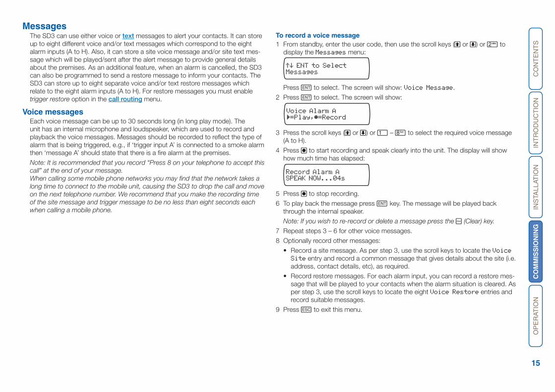
To record a voice message1 From standby, enter the user code, then use the scroll keys (A or C) or 2 to
display the Messages menu:
Messages
Press E to select. The screen will show: Voice Message.
2 Press E to select. The screen will show:
¶=Play,µ=RecordVoice Alarm A
3 Press the scroll keys (A or C) or 1 – 8 to select the required voice message (A to H).
4 Press B to start recording and speak clearly into the unit. The display will show how much time has elapsed:
SPEAK NOW...04sRecord Alarm A
5 Press B to stop recording.
6 To play back the message press E key. The message will be played back through the internal speaker.
Note: If you wish to re-record or delete a message press the D (Clear) key.
7 Repeat steps 3 – 6 for other voice messages.
8 Optionally record other messages:
• Record a site message. As per step 3, use the scroll keys to locate the Voice Site entry and record a common message that gives details about the site (i.e. address, contact details, etc), as required.
• Record restore messages. For each alarm input, you can record a restore mes-sage that will be played to your contacts when the alarm situation is cleared. As per step 3, use the scroll keys to locate the eight Voice Restore entries and record suitable messages.
9 Press F to exit this menu.
CO
NT
EN
TS
INT
RO
DU
CT
ION
INS
TALL
ATIO
NC
OM
MIS
SIO
NIN
GO
PE
RAT
ION
16
Text messagesThe SD3 can send text messages to mobile telephones using the standard SMS (Short Message Service) messaging. The unit can store up to eight alarm mes-sages, each with up to 40-characters.
Note: The optional GSM module is required to allow the SD3 to send text messages.
When the unit sends a text message, it adds the “site message” with a time and date stamp (see Set date and time).
Messages should normally hold the name or details of the location being protect-ed.
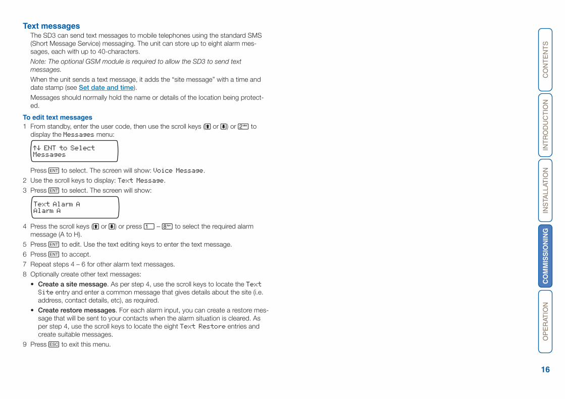
To edit text messages1 From standby, enter the user code, then use the scroll keys (A or C) or 2 to
display the Messages menu:
Messages
Press E to select. The screen will show: Voice Message.
2 Use the scroll keys to display: Text Message.
3 Press E to select. The screen will show:
Alarm AText Alarm A
4 Press the scroll keys (A or C) or press 1 – 8 to select the required alarm message (A to H).
5 Press E to edit. Use the text editing keys to enter the text message.
6 Press E to accept.
7 Repeat steps 4 – 6 for other alarm text messages.
8 Optionally create other text messages:
• Create a site message. As per step 4, use the scroll keys to locate the Text Site entry and enter a common message that gives details about the site (i.e. address, contact details, etc), as required.
• Create restore messages. For each alarm input, you can create a restore mes-sage that will be sent to your contacts when the alarm situation is cleared. As per step 4, use the scroll keys to locate the eight Text Restore entries and create suitable messages.
9 Press F to exit this menu.
CO
NT
EN
TS
INT
RO
DU
CT
ION
INS
TALL
ATIO
NC
OM
MIS
SIO
NIN
GO
PE
RAT
ION
17
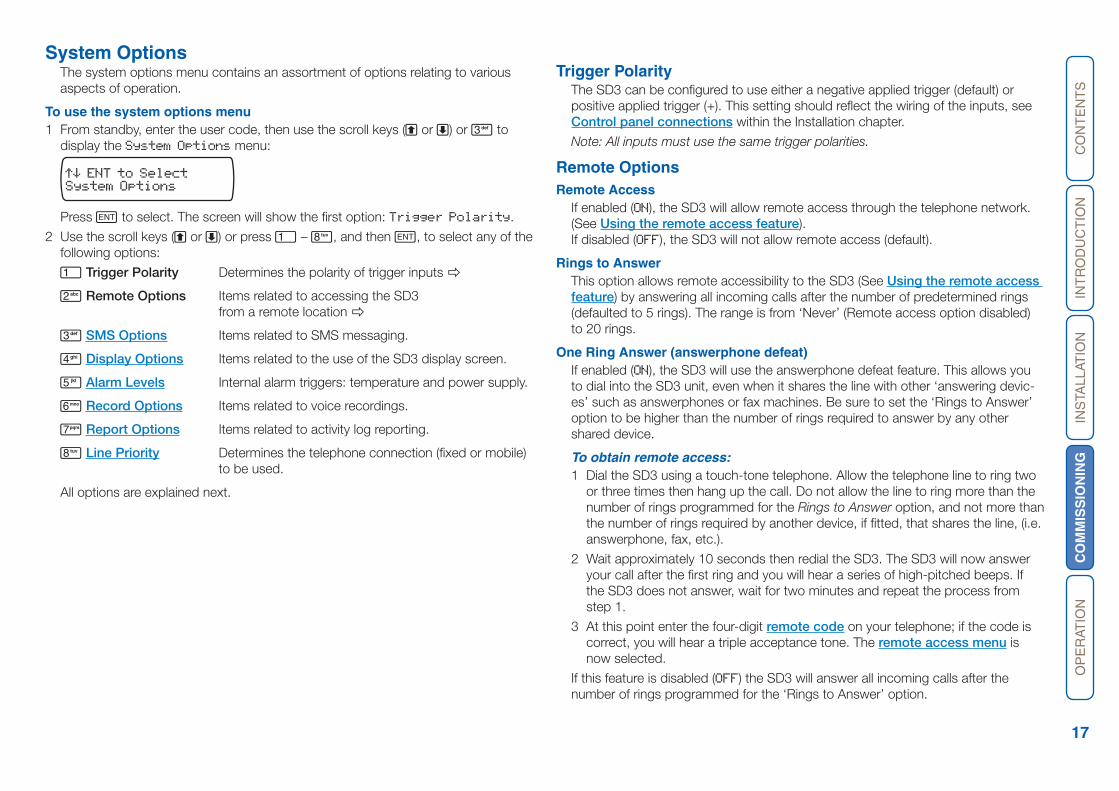
System OptionsThe system options menu contains an assortment of options relating to various aspects of operation.
To use the system options menu1 From standby, enter the user code, then use the scroll keys (A or C) or 3 to
display the System Options menu:
System Options
Press E to select. The screen will show the first option: Trigger Polarity.
2 Use the scroll keys (A or C) or press 1 – 8, and then E, to select any of the following options:
1 Trigger Polarity Determines the polarity of trigger inputs
2 Remote Options Items related to accessing the SD3 from a remote location
3 SMS Options Items related to SMS messaging.
4 Display Options Items related to the use of the SD3 display screen.
5 Alarm Levels Internal alarm triggers: temperature and power supply.
6 Record Options Items related to voice recordings.
7 Report Options Items related to activity log reporting.
8 Line Priority Determines the telephone connection (fixed or mobile) to be used.
All options are explained next.
Trigger PolarityThe SD3 can be configured to use either a negative applied trigger (default) or positive applied trigger (+). This setting should reflect the wiring of the inputs, see Control panel connections within the Installation chapter.
Note: All inputs must use the same trigger polarities.
Remote OptionsRemote Access
If enabled (ON), the SD3 will allow remote access through the telephone network. (See Using the remote access feature). If disabled (OFF), the SD3 will not allow remote access (default).
Rings to AnswerThis option allows remote accessibility to the SD3 (See Using the remote access feature) by answering all incoming calls after the number of predetermined rings (defaulted to 5 rings). The range is from ‘Never’ (Remote access option disabled) to 20 rings.
One Ring Answer (answerphone defeat)If enabled (ON), the SD3 will use the answerphone defeat feature. This allows you to dial into the SD3 unit, even when it shares the line with other ‘answering devic-es’ such as answerphones or fax machines. Be sure to set the ‘Rings to Answer’ option to be higher than the number of rings required to answer by any other shared device.
To obtain remote access:1 Dial the SD3 using a touch-tone telephone. Allow the telephone line to ring two
or three times then hang up the call. Do not allow the line to ring more than the number of rings programmed for the Rings to Answer option, and not more than the number of rings required by another device, if fitted, that shares the line, (i.e. answerphone, fax, etc.).
2 Wait approximately 10 seconds then redial the SD3. The SD3 will now answer your call after the first ring and you will hear a series of high-pitched beeps. If the SD3 does not answer, wait for two minutes and repeat the process from step 1.
3 At this point enter the four-digit remote code on your telephone; if the code is correct, you will hear a triple acceptance tone. The remote access menu is now selected.
If this feature is disabled (OFF) the SD3 will answer all incoming calls after the number of rings programmed for the ‘Rings to Answer’ option.

CO
NT
EN
TS
INT
RO
DU
CT
ION
INS
TALL
ATIO
NC
OM
MIS
SIO
NIN
GO
PE
RAT
ION
18
SMS OptionsSMS Call Number
This option allows the editing of the default SMS service centre number used by the SD3 to send text messages.
The SD3 defaults to the O2 SMS centre. Listed below are other service centres that can be used:
Service Provider Telephone No. Format Protocol
O2 - UK +44 (0) 7860 980480 8,N, 1 TAP
One2One- UK +44 (0) 7958 879889 7,E, 1 TAP
Vodafone Mobiles - UK +44 (0) 7785 499993 8,N, 1 TAP
Note: If your SD3 is connected to a private telephone system, remember that you may have to include an extra digit (for example ‘9’) to gain access to the public telephone network.
If you are calling an SMS service centre in a different country you need to make sure that the contact’s mobile telephone number has the international country code, e.g., if the contact’s UK mobile number is 07801 123456 it needs to be entered as 447801123456.
SMS FormatThe SD3 can be configured to communicate with the SMS service centre either using 7 data bits with even parity and 1 stop bit, or using 8 data bits with no par-ity and 1 stop bit. See ‘SMS Call Number’ for further details. When going via a switchboard system, remember to insert the number used to get an external line (normally 9).
SMS ProtocolThe messaging protocol used by each service centre may vary from one provider to another. The SMS Protocol option allows you to select either TAP or UCP.
SD3 Telephone NumberIf you chose to use UCP protocol, then you can employ this option to store a number that the SD3 transmits as part of the SMS message. Normally you should store the telephone number of the calling SD3. Note that the SD3 Telephone Number option does not apply to TAP SMS protocol.
Display OptionsFlash On Message
• If enabled (ON), the SD3 will flash the display backlight on and off when a memo message is waiting (default). Listening to the memo message stops the back-light flashing.
• If disabled (OFF), the SD3 will not flash the display backlight.
Beep On Message• If enabled (ON), the SD3 will beep every minute when a memo message is wait-
ing. Listening to the message cancels the beep.
• If disabled (OFF), the SD3 will not beep (default).
Temp Display• If enabled (ON), the SD3’s display will show the current ambient temperature in
degrees centigrade, (default).
• If disabled (OFF), the SD3’s display will not show the ambient temperature.
Line Fault• If enabled (Display and Beep) the SD3 logs any line fault and displays ‘line
fault’ on the display; it also produces an audible tone every 60 seconds. Enter-ing programming mode will silence the audible tone if the line fault persists.
(Note that the SD3 may take up to 60 seconds to display the fault.)
• If set to Display On then the SD3 logs and displays the fault, but does not make any audible alert.
• If Disabled (Display Off) the SD3 logs any line fault, (default).
CO
NT
EN
TS
INT
RO
DU
CT
ION
INS
TALL
ATIO
NC
OM
MIS
SIO
NIN
GO
PE
RAT
ION
19
Alarm LevelsTemperature High
This option allows you to set the temperature at which the temperature high alarm output will activate (see also Outputs). Working range of 0°C to 50°C (default 40°C).
Temperature LowThis option allows you to set the temperature at which the temperature low alarm output will activate (see also Outputs). Working range of 0°C to 50°C (default 5°C).
Supply LowThis option allows you to set a supply voltage level, below which an alarm output is activated (see also Outputs). A Supply Low message will also appear in the event log.
Signal LowThis option allows you to set a signal level. If the GSM signal level drops below the level set here an output is activated (see also Outputs). A GSM Sig. Low mes-sage will also appear in the event log.
Record OptionsLong play
• If enabled (ON), the recordable messages have a maximum record time of 30 seconds.
• If disabled (OFF), the recordable messages have a maximum record time of 15 seconds; also the speech is of a higher quality, (default).
Auto Record• If enabled (ON), the SD3 will automatically switch the microphone on and start
recording for up to 15 or 30 seconds (depending on the ‘Long Play’ option setting) when any trigger input is present. The recording is then stored in the ‘Memo feature‘. The recording can then be accessed either using the remote access feature (see Using the remote access feature) or via the memo play-back feature via the keypad (see Recording and playing a memo locally). The Message Waiting output option can also be used with this feature.
• If disabled (OFF), the SD3 will not automatically record a message (default).
Report OptionsAuto Reporting
If enabled (ON), the SD3 will automatically call any programmed numbers in the ‘Call Routing > Auto Report > Route Auto Rep.’ menu – every 24 hours. (See Call Routing) and send the site message. The ‘report time’ can be adjusted to the hour required. See Report Time below. (This option defaults to OFF).
Note: The auto reporting messages require acknowledgements. Without acknowl-edgement the messages will repeat a number of times.
Report TimeThis option sets the time that the Auto Reporting message is transmitted (De-fault 12:00 hours).
Press the scroll keys to select the required hour.
Line PriorityThis option determines which line(s) should be used to make alarm calls and can be set to one of the following:
PSTN OnlyAlarm calls will be made via the fixed (wired) line only.
GSM OnlyAlarm calls will be made via the GSM mobile module only (if fitted).
PSTN FirstAn alarm call will be attempted via wired (PSTN) line first. If the call fails due to local PSTN line not present, an attempt will be made via the GSM module.
GSM FirstAn alarm call will attempted via the GSM mobile module line first (if fitted) and if the call fails due to insufficient signal, an attempt will be made via the wired line.

CO
NT
EN
TS
INT
RO
DU
CT
ION
INS
TALL
ATIO
NC
OM
MIS
SIO
NIN
GO
PE
RAT
ION
20
Access CodesThe SD3 operation is protected by two main codes:
• The user code A 4-digit code which is required, when using the unit locally, to gain access to the programming menus. The user code is also used for aborting calls. The default user code is ‘1234’.
• The remote code A 4-digit code that is used, when dialling into the unit from a remote location, to gain access to the remote access menu (see Using the re-mote access feature). The default remote code is ‘5678’.
To change the user code1 From standby, enter the user code, then use the scroll keys (A or C) or 4 to
display the Access Codes menu:
Access Codes
Press E to select. The screen will show: Edit User Code.
2 Press E to select. The screen will show:
****
New User Code ?
3 Enter a new four-digit user code and press E to accept.
4 Press F to exit this menu.
To change the remote code1 From standby, enter the user code, then use the scroll keys (A or C) or 4 to
display the Access Codes menu:
Access Codes
Press E to select. The screen will show: Edit User Code.
2 Use the scroll key (C) or 2 to display: Edit Remote Code.
3 Press E to select. The screen will show:
****
New Remote Code ?
4 Enter a new four-digit remote code and press E to accept.
5 Press F to exit this menu.
CO
NT
EN
TS
INT
RO
DU
CT
ION
INS
TALL
ATIO
NC
OM
MIS
SIO
NIN
GO
PE
RAT
ION
21
Acknowledgement and Abort Options Abort Options
Occasionally, the SD3 may be triggered accidentally, causing it to send an unwant-ed call. The various ‘Abort Options’ allow you to determine how false alarm condi-tions can be cancelled. When a call is aborted the SD3 immediately hangs-up and returns to its normal standby mode.
Note: The initial alert text message cannot be aborted as it is sent almost instantly when an alarm trigger occurs.
To select an abort option1 From standby, enter the user code, then use the scroll keys (A or C) or 5 to
display the Ack & Abort menu:
Ack & Abort
Press E to select. The screen will show: Abort Options.
2 Press E to select. The screen will show the currently selected option: None (de-fault).
3 Use the scroll keys (A or C) and then E, to select any of the following options:
None Trigger inputs cannot be aborted, (default).
Passcode Only The selected trigger input can only be aborted by en-tering the user code into the SD3.
Code or Restore The selected trigger input can be aborted by either entering the user code into the SD3 or by restoring the trigger input to its normal healthy condition.
Restore Only The selected trigger input can only be aborted by re-storing the trigger input to its normal healthy condition.
Clear by OptionsOnce the SD3 has made its call and delivered its message it requires a sig-nal, from the contacted person, to say that the message has been successfully received and accepted. To accept a call, the recipient must press the number 8 button on their telephone at any time during the call. If a call is not accepted, the SD3 will dial the next programmed contact number.
The ‘Clear By Options’ allow you to determine whether the SD3 should cease call-ing your contacts after the first acknowledgement or continue calling all contacts.
To select a clear by option1 From standby, enter the user code, then use the scroll keys (A or C) or 5 to
display the Ack & Abort menu:
Ack & Abort
Press E to select. The screen will show: Abort Options.
2 Press the scroll key (C) to display: Clear By Options.
3 Press E to select. The screen will show the currently selected option: Anyone (default).
4 Use the scroll keys (A or C) and then E, to select either of the following options:
Anyone When the SD3 has been acknowledged, it will shut down until it is triggered again.
No One The SD3 will contact all programmed contact numbers.
CO
NT
EN
TS
INT
RO
DU
CT
ION
INS
TALL
ATIO
NC
OM
MIS
SIO
NIN
GO
PE
RAT
ION
22
OutputsThe SD3 has four programmable outputs (OP1 to OP4) that can be accessed re-motely and used for a wide variety of functions (for example: switching on lighting or heating/ventilation systems).
To program an output1 From standby, enter the user code, then use the scroll keys (A or C) or 6 to
display the Outputs menu:
Outputs
Press E to select. The screen will show: Output 1.
2 If necessary, select the required output port (Output 1 to Output 4) using the scroll keys (A or C) and then press E to select. The screen will show the cur-rently selected option: OFF (default).
3 Use the scroll keys (A or C) and then E, to select any of the following options:
OFF The output remains off at all times.
Message Waiting This output type activates when the SD3 has a Mes-sage waiting and de-activates once the Message has been played.
Remote Access This output activates when the SD3 is being accessed remotely with a touch-tone telephone. The output de-activates when call has finished.
Temperature High This output activates when the Temperature High set-ting has been reached. The output de-activates once the temperature falls below the preset temperature (see Alarm Levels).
Temperature Low This output activates when the Temperature Low set-ting has been reached. The output de-activates once the temperature rises above the preset temperature (see Alarm Levels).
Listen Active This output type activates when the SD3 is using the Listen In feature (see Listen-in & talkback mode).
Speech Active This output type activates when the SD3 is using the Talk Back feature (see Listen-in & talkback mode).
Phone Line Fault This output type will activate when telephone line con-nected to the unit has a fault, i.e. line disconnected or no line voltage after 50 seconds.
PSTN In Use This output type activates when the SD3 is using the fixed telephone line.
GSM In Use This output type activates when the SD3 is using the mobile telephone link.
Call Active This output type activates when the SD3 is active, i.e. after the unit has been triggered. The output de-acti-vates once the unit has dialled all its contacts or the call is aborted.
Call Successful This output type activates when the SD3 has delivered its message successfully. The output de-activates when the unit is next triggered.
Call Failed This output type activates when the SD3 fails to deliver its message. The output de-activates when the unit is next triggered.
Remote Control 1-4 These output types can be remotely turned on and off by a touchtone telephone. e.g., switching on lighting or heating/ventilation systems.
Supply Volts Low This output type activates when the SD3 supply volt-age drops below 10.5 Volts. (see Alarm Levels).
GSM Signal Low This output type activates when the GSM signal level falls below the level set in the Signal Low option. (see Alarm Levels).
CO
NT
EN
TS
INT
RO
DU
CT
ION
INS
TALL
ATIO
NC
OM
MIS
SIO
NIN
GO
PE
RAT
ION
23
Call Routing OptionsCall routing options allow you to determine which contacts should receive certain (voice or text) messages. For instance, you may require alarm message A to be sent to contacts 1, 3 and 5, while alarm message B should go only to contacts 2,6, 7 and 8. Similarly, the optional Auto Report, which is sent out every 24 hours, can be sent to one or more chosen contacts. There are three call routing options and each is configured in a similar manner:
• Trigger Alarm Determines which contacts (1 to 10) should be called when a particular alarm is triggered.
• Trigger Restore Determines which contacts (1 to 10) should be called when a particular alarm returns to its normal state (for example when the alarm system has been reset after an alarm activation).
• Auto Report Determines which contacts will be notified every 24 hours by the test call facility.
To program call routing options1 From standby, enter the user code, then use the scroll keys (A or C) or 7 to
display the Call Routing menu:
Call Routing
Press E to select. The screen will show: Trigger Alarm. If necessary, use the scroll keys (A or C) to select the Trigger Restore or Auto Report options.
2 Press E to select. The screen will show:
To 1234567890Route A Alarm
Note: Trigger restore mode will show Route A Restore and Auto Report mode will show: Route Auto Rep.
3 Each number represents a contact (1 to 10). Use the numeric keys (1 to 0) to include or exclude a contact from the chosen message. If a contact in included, its number will be shown, whereas, if a contact is excluded, its number will be replaced by an asterisk (*). In the screen shown below, contacts 2, 5 and 8 have been excluded from receiving alarm message A.
To 1*34*67*90Route A Alarm
4 To change to a different alarm message, use the scroll keys (A or C).
5 When all settings have been made, press E to store and exit. Then press F to exit from the Call Routing menu.
Set Date and TimeThis option allows you to adjust the SD3’s date and time. The clock is in 24-hour format and is used for providing the date and time stamp for the event log, text messaging and for the standby display.
Note: The clock is intended as a guide only.
To adjust the date and time1 From standby, enter the user code, then use the scroll keys (A or C) or 8 to
display the Date & Time menu:
Date & Time
Press E to select. The screen will show the current date setting.
2 Use the numeric keys to enter the date (in the form: dd/mm/yy) and then press E. The screen will now show the current time.
3 Use the numeric keys to enter the time (in 24-hour format) and then press E.
4 Press F to exit.
CO
NT
EN
TS
INT
RO
DU
CT
ION
INS
TALL
ATIO
NC
OM
MIS
SIO
NIN
GO
PE
RAT
ION
24
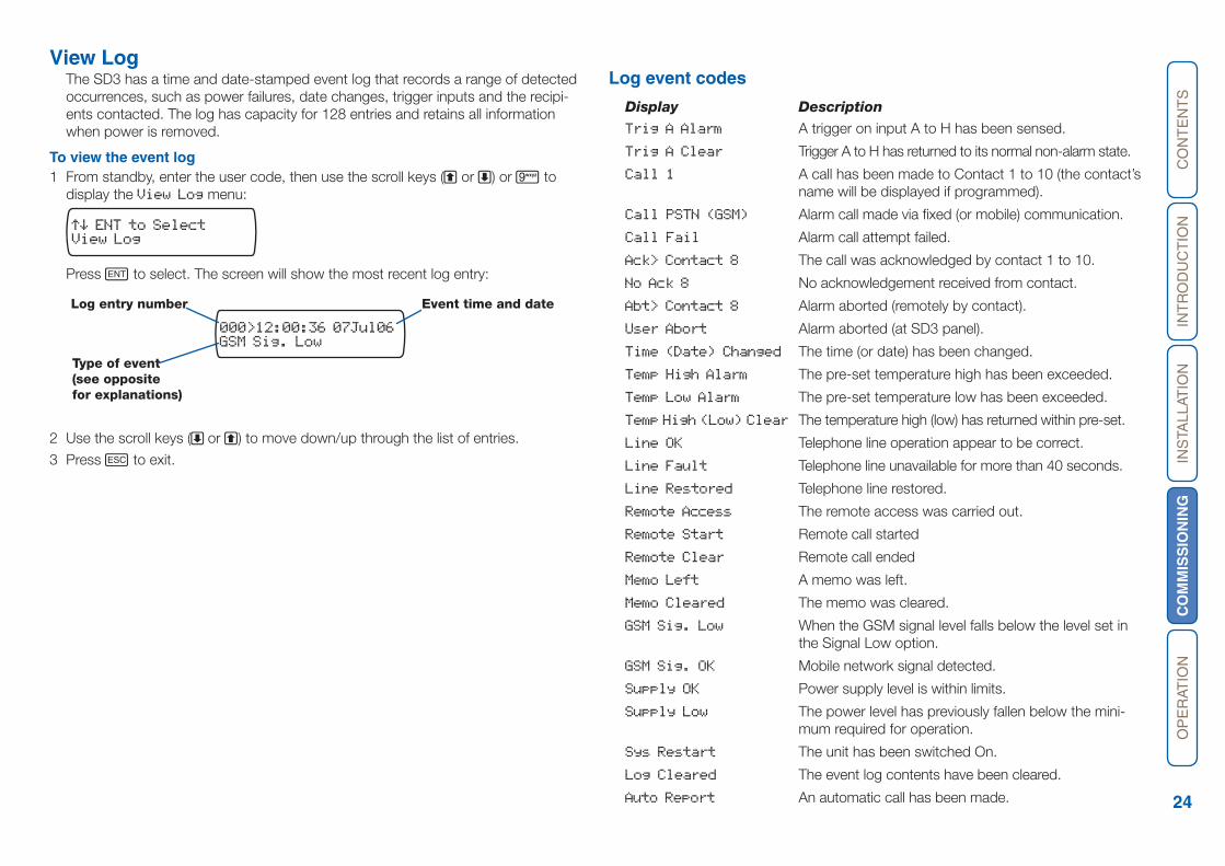
View LogThe SD3 has a time and date-stamped event log that records a range of detected occurrences, such as power failures, date changes, trigger inputs and the recipi-ents contacted. The log has capacity for 128 entries and retains all information when power is removed.
To view the event log1 From standby, enter the user code, then use the scroll keys (A or C) or 9 to
display the View Log menu:
View Log
Press E to select. The screen will show the most recent log entry:
2 Use the scroll keys (C or A) to move down/up through the list of entries.
3 Press F to exit.
GSM Sig. Low000>12:00:36 07Jul06
Log entry number Event time and date
Type of event (see opposite for explanations)
Log event codes
Display Description
Trig A Alarm A trigger on input A to H has been sensed.
Trig A Clear Trigger A to H has returned to its normal non-alarm state.
Call 1 A call has been made to Contact 1 to 10 (the contact’s name will be displayed if programmed).
Call PSTN (GSM) Alarm call made via fixed (or mobile) communication.
Call Fail Alarm call attempt failed.
Ack> Contact 8 The call was acknowledged by contact 1 to 10.
No Ack 8 No acknowledgement received from contact.
Abt> Contact 8 Alarm aborted (remotely by contact).
User Abort Alarm aborted (at SD3 panel).
Time (Date) Changed The time (or date) has been changed.
Temp High Alarm The pre-set temperature high has been exceeded.
Temp Low Alarm The pre-set temperature low has been exceeded.
Temp High (Low) Clear The temperature high (low) has returned within pre-set.
Line OK Telephone line operation appear to be correct.
Line Fault Telephone line unavailable for more than 40 seconds.
Line Restored Telephone line restored.
Remote Access The remote access was carried out.
Remote Start Remote call started
Remote Clear Remote call ended
Memo Left A memo was left.
Memo Cleared The memo was cleared.
GSM Sig. Low When the GSM signal level falls below the level set in the Signal Low option.
GSM Sig. OK Mobile network signal detected.
Supply OK Power supply level is within limits.
Supply Low The power level has previously fallen below the mini-mum required for operation.
Sys Restart The unit has been switched On.
Log Cleared The event log contents have been cleared.
Auto Report An automatic call has been made.
CO
NT
EN
TS
INT
RO
DU
CT
ION
INS
TALL
ATIO
NC
OM
MIS
SIO
NIN
GO
PE
RAT
ION
25
Test OptionsThe SD3 has seven test options:
1 Test Messages 2 Test Outputs
3 Test Triggers
4 Test Line5 Test Supply
6 GSM Phone Utilities
7 Software Version
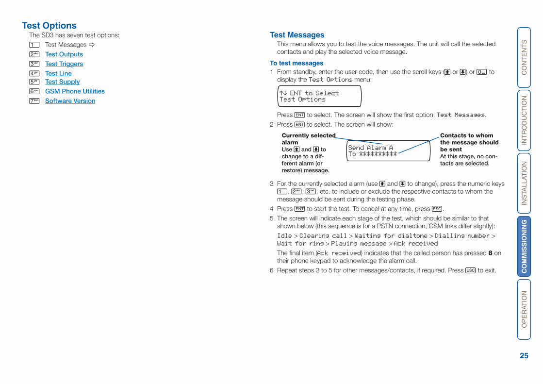
To **********Send Alarm A
Currently selected alarm Use A and C to change to a dif-ferent alarm (or restore) message.
Contacts to whom the message should be sentAt this stage, no con-tacts are selected.
Test MessagesThis menu allows you to test the voice messages. The unit will call the selected contacts and play the selected voice message.
To test messages1 From standby, enter the user code, then use the scroll keys (A or C) or 0 to
display the Test Options menu:
Test Options
Press E to select. The screen will show the first option: Test Messages.
2 Press E to select. The screen will show:
3 For the currently selected alarm (use A and C to change), press the numeric keys 1, 2, 3, etc. to include or exclude the respective contacts to whom the message should be sent during the testing phase.
4 Press E to start the test. To cancel at any time, press F.
5 The screen will indicate each stage of the test, which should be similar to that shown below (this sequence is for a PSTN connection, GSM links differ slightly):
Idle > Clearing call > Waiting for dialtone > Dialling number > Wait for ring > Playing message > Ack received
The final item (Ack received) indicates that the called person has pressed 8 on their phone keypad to acknowledge the alarm call.
6 Repeat steps 3 to 5 for other messages/contacts, if required. Press F to exit.
CO
NT
EN
TS
INT
RO
DU
CT
ION
INS
TALL
ATIO
NC
OM
MIS
SIO
NIN
GO
PE
RAT
ION
26
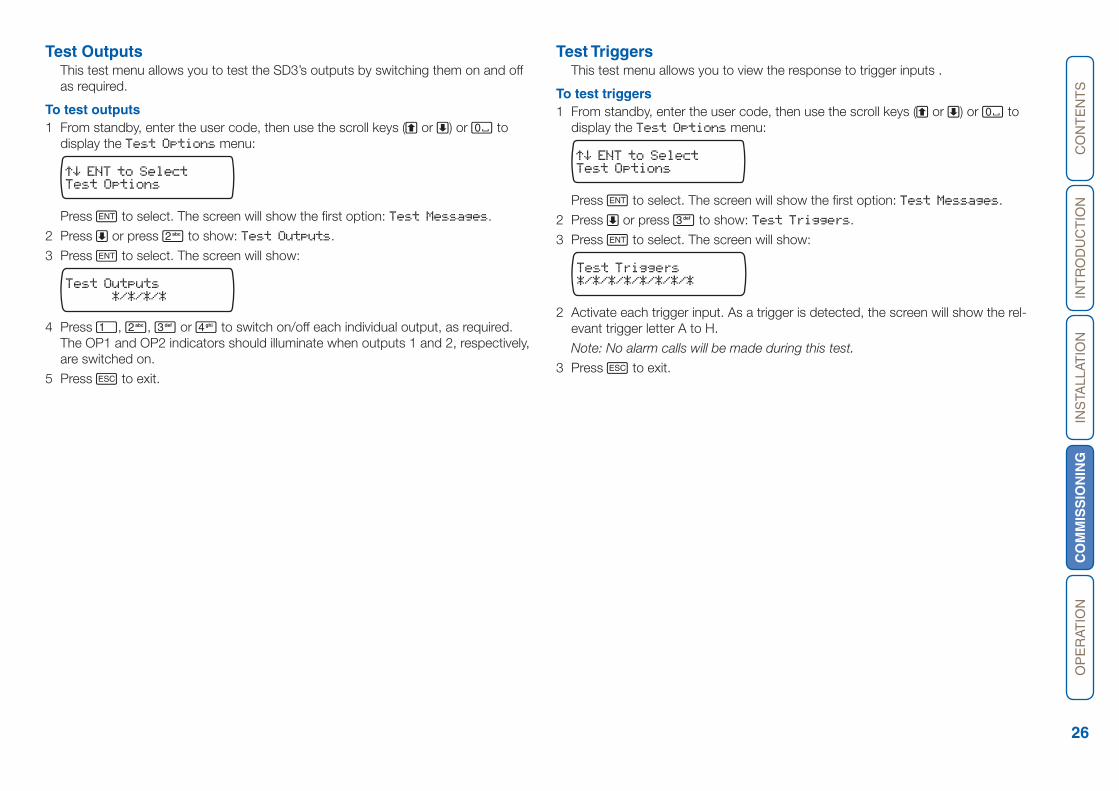
Test OutputsThis test menu allows you to test the SD3’s outputs by switching them on and off as required.
To test outputs 1 From standby, enter the user code, then use the scroll keys (A or C) or 0 to
display the Test Options menu:
Test Options
Press E to select. The screen will show the first option: Test Messages.
2 Press C or press 2 to show: Test Outputs.
3 Press E to select. The screen will show:
*/*/*/*
Test Outputs
4 Press 1, 2, 3 or 4 to switch on/off each individual output, as required. The OP1 and OP2 indicators should illuminate when outputs 1 and 2, respectively, are switched on.
5 Press F to exit.
Test TriggersThis test menu allows you to view the response to trigger inputs .
To test triggers1 From standby, enter the user code, then use the scroll keys (A or C) or 0 to
display the Test Options menu:
Test Options
Press E to select. The screen will show the first option: Test Messages.
2 Press C or press 3 to show: Test Triggers.
3 Press E to select. The screen will show:
*/*/*/*/*/*/*/*Test Triggers
2 Activate each trigger input. As a trigger is detected, the screen will show the rel-evant trigger letter A to H.
Note: No alarm calls will be made during this test.
3 Press F to exit.
CO
NT
EN
TS
INT
RO
DU
CT
ION
INS
TALL
ATIO
NC
OM
MIS
SIO
NIN
GO
PE
RAT
ION
27
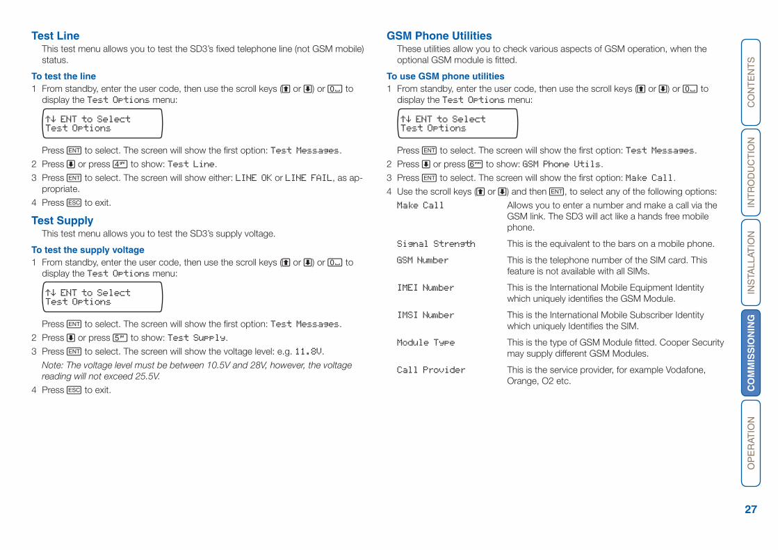
Test LineThis test menu allows you to test the SD3’s fixed telephone line (not GSM mobile) status.
To test the line1 From standby, enter the user code, then use the scroll keys (A or C) or 0 to
display the Test Options menu:
Test Options
Press E to select. The screen will show the first option: Test Messages.
2 Press C or press 4 to show: Test Line.
3 Press E to select. The screen will show either: LINE OK or LINE FAIL, as ap-propriate.
4 Press F to exit.
Test SupplyThis test menu allows you to test the SD3’s supply voltage.
To test the supply voltage1 From standby, enter the user code, then use the scroll keys (A or C) or 0 to
display the Test Options menu:
Test Options
Press E to select. The screen will show the first option: Test Messages.
2 Press C or press 5 to show: Test Supply.
3 Press E to select. The screen will show the voltage level: e.g. 11.8V.
Note: The voltage level must be between 10.5V and 28V, however, the voltage reading will not exceed 25.5V.
4 Press F to exit.
GSM Phone UtilitiesThese utilities allow you to check various aspects of GSM operation, when the optional GSM module is fitted.
To use GSM phone utilities1 From standby, enter the user code, then use the scroll keys (A or C) or 0 to
display the Test Options menu:
Test Options
Press E to select. The screen will show the first option: Test Messages.
2 Press C or press 6 to show: GSM Phone Utils.
3 Press E to select. The screen will show the first option: Make Call.
4 Use the scroll keys (A or C) and then E, to select any of the following options:
Make Call Allows you to enter a number and make a call via the GSM link. The SD3 will act like a hands free mobile phone.
Signal Strength This is the equivalent to the bars on a mobile phone.
GSM Number This is the telephone number of the SIM card. This feature is not available with all SIMs.
IMEI Number This is the International Mobile Equipment Identity which uniquely identifies the GSM Module.
IMSI Number This is the International Mobile Subscriber Identity which uniquely Identifies the SIM.
Module Type This is the type of GSM Module fitted. Cooper Security may supply different GSM Modules.
Call Provider This is the service provider, for example Vodafone, Orange, O2 etc.
CO
NT
EN
TS
INT
RO
DU
CT
ION
INS
TALL
ATIO
NC
OM
MIS
SIO
NIN
GO
PE
RAT
ION
28
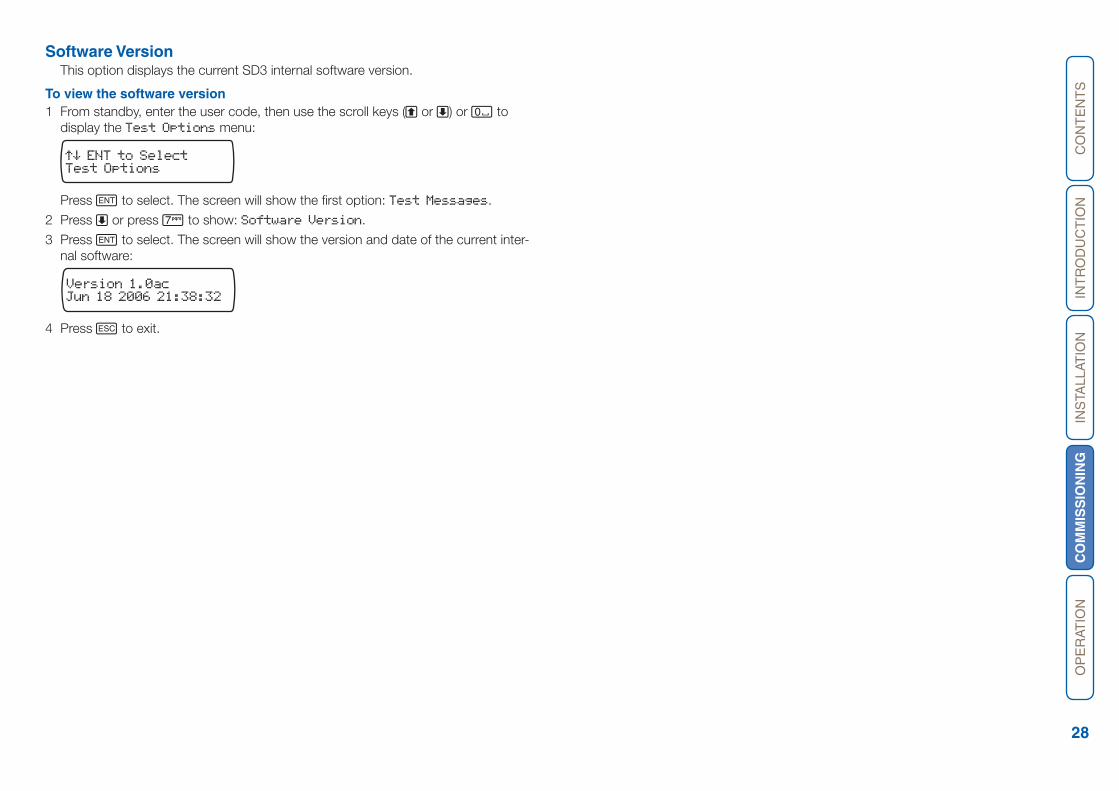
Software VersionThis option displays the current SD3 internal software version.
To view the software version1 From standby, enter the user code, then use the scroll keys (A or C) or 0 to
display the Test Options menu:
Test Options
Press E to select. The screen will show the first option: Test Messages.
2 Press C or press 7 to show: Software Version.
3 Press E to select. The screen will show the version and date of the current inter-nal software:
Jun 18 2006 21:38:32Version 1.0ac
4 Press F to exit.
CO
NT
EN
TS
INT
RO
DU
CT
ION
INS
TALL
ATIO
NC
OM
MIS
SIO
NIN
GO
PE
RA
TIO
N
29
Operation
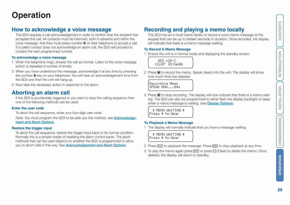
How to acknowledge a voice messageThe SD3 requires a call acknowledgement in order to confirm that the recipient has accepted the call. All contacts must be informed, both in advance and within the voice message, that they must press number 8 on their telephone to accept a call. If a called contact does not acknowledge an alarm call, the SD3 will proceed to contact the next programmed number.
To acknowledge a voice message1 When the telephone rings, answer the call as normal. Listen to the voice message
(which is repeated a number of times).
2 When you have understood the message, acknowledge it at any time by pressing the number 8 key on your telephone. You will hear an acknowledgement tone from the SD3 and then the unit will hang up.
3 Now take the necessary action in response to the alarm.
Aborting an alarm callIf the SD3 is accidentally triggered or you want to stop the calling sequence then one of the following methods can be used:
Enter the user codeTo abort the call sequence, enter your four-digit user code.
Note: You must program the SD3 to be able use this method, see Acknowledge-ment and Abort Options.
Restore the trigger inputTo abort the call sequence, restore the trigger input back to its normal condition. Normally this is a simple matter of resetting the alarm control panel. The abort methods that can be used depend on whether the SD3 is programmed to allow you to abort calls in this way. See Acknowledgement and Abort Options.
Recording and playing a memo locally The SD3 has an in-built memo facility to record a voice memo message at the keypad that can be up to sixteen seconds in duration. Once recorded, the display will indicate that there is a memo message waiting.
To Record A Memo Message1 Ensure the unit is in normal mode and displaying the standby screen:
SD3 +29°C12:07 01Jan06
2 Press B to record the memo. Speak clearly into the unit. The display will show how much time has elapsed:
SPEAK NOW...04sRecording Memo
3 Press B to stop recording. The display will now indicate that there is a memo wait-ing. The SD3 can also be programmed to either flash the display backlight or beep when a memo message is waiting, (see Display Options).
Press to Hear
* MEMO WAITING *
To Playback a Memo Message1 The display will normally indicate that you have a message waiting:
Press to Hear
* MEMO WAITING *
2 Press E to playback the message. Press F to stop playback at any time.
3 To play the memo again press E or press D (Clear) to delete the memo. Once deleted, the display will return to standby.
HL
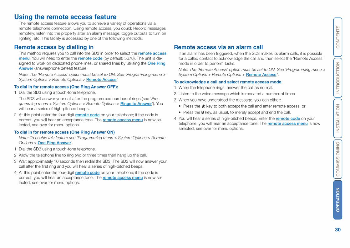
CO
NT
EN
TS
INT
RO
DU
CT
ION
INS
TALL
ATIO
NC
OM
MIS
SIO
NIN
GO
PE
RA
TIO
N
30
Using the remote access featureThe remote access feature allows you to achieve a variety of operations via a remote telephone connection. Using remote access, you could: Record messages remotely; listen into the property after an alarm message; toggle outputs to turn on lighting, etc. This facility is accessed by one of the following methods:
Remote access by dialling inThis method requires you to call into the SD3 in order to select the remote access menu. You will need to enter the remote code (by default: 5678). The unit is de-signed to work on dedicated phone lines, or shared lines by utilising the One Ring Answer (answerphone defeat) feature.
Note: The ‘Remote Access’ option must be set to ON. See ‘Programming menu > System Options > Remote Options > Remote Access’.
To dial in for remote access (One Ring Answer OFF):1 Dial the SD3 using a touch-tone telephone.
The SD3 will answer your call after the programmed number of rings (see ‘Pro-gramming menu > System Options > Remote Options > Rings to Answer’). You will hear a series of high-pitched beeps.
2 At this point enter the four-digit remote code on your telephone; if the code is correct, you will hear an acceptance tone. The remote access menu is now se-lected, see over for menu options.
To dial in for remote access (One Ring Answer ON)Note: To enable this feature see ‘Programming menu > System Options > Remote Options > One Ring Answer’.
1 Dial the SD3 using a touch-tone telephone.
2 Allow the telephone line to ring two or three times then hang up the call.
3 Wait approximately 10 seconds then redial the SD3. The SD3 will now answer your call after the first ring and you will hear a series of high-pitched beeps.
4 At this point enter the four-digit remote code on your telephone; if the code is correct, you will hear an acceptance tone. The remote access menu is now se-lected, see over for menu options.
Remote access via an alarm callIf an alarm has been triggered, when the SD3 makes its alarm calls, it is possible for a called contact to acknowledge the call and then select the ‘Remote Access’ mode in order to perform tasks.
Note: The ‘Remote Access’ option must be set to ON. See ‘Programming menu > System Options > Remote Options > Remote Access’’.
To acknowledge a call and select remote access mode1 When the telephone rings, answer the call as normal.
2 Listen to the voice message which is repeated a number of times.
3 When you have understood the message, you can either:
• Press the * key to both accept the call and enter remote access, or
• Press the 8 key, as usual, to merely accept and end the call.
4 You will hear a series of high-pitched beeps. Enter the remote code on your telephone, you will hear an acceptance tone. The remote access menu is now selected, see over for menu options.

CO
NT
EN
TS
INT
RO
DU
CT
ION
INS
TALL
ATIO
NC
OM
MIS
SIO
NIN
GO
PE
RA
TIO
N
31
The remote access menuThe following commands can be selected from the remote access menu using the keypad of your touch-tone phone:
Function Phone key sequence
Toggle output 1 *11
Toggle output 2 *12
Toggle output 3 *13
Toggle output 4 *14
Listen-in/talkback mode *3 then subsequently 3 to change between listen-in and talkback modes. 0 to quit listen-in/talk back modes.
Play alarm voice messages 1 to 8 4 followed by 1 to 8
Record alarm voice messages 1 to 8 *4 followed by 1 to 8 (0 to stop)
Play restore messages 1 to 8 5 followed by 1 to 8
Record restore messages 1 to 8 *5 followed by 1 to 8 (0 to stop)
Enter contact phone numbers 1 to 10 *7 followed by 1 to 0 (0 = 10) and then enter the appropriate phone number twice, each time followed by #. Note: If number is entered incorrectly, the error beep will be heard.
Test alarm messages 1 to 10 after remote access mode is terminated *8 followed by 1 to 0 (0 = 10).
Playback memo 0
Record memo *0 then subsequently 0 or any key to stop recording and playback.
Quit remote access menu and hang-up #
Notes:
The ‘Remote Access’ option must be set to ON. See ‘Programming menu > Sys-tem Options > Remote Options > Remote Access’.
If after 60 seconds no command has been selected then SD3 will hang-up the call. Once a command has been selected, the unit remains online for 5 minutes or until the quit remote access command is used (#).
Toggle outputsThe remote access menu allows you to change (toggle) the on/off state of the SD3 outputs 1 to 4.
Note: The ‘Remote Access’ option must be set to ON. See ‘Programming menu > System Options > Remote Options > Remote Access’.
To toggle outputs1 Establish a remote access connection with the SD3, as discussed earlier within
this section.
2 Press the keys on your telephone to affect the outputs, as follows:
SD3 output Press You will hear
Toggle output 1 *11 On: 1 high-pitch beep, Off: 1 low-pitch beep
Toggle output 2 *12 On: 2 high-pitch beeps, Off: 2 low-pitch beeps
Toggle output 3 *13 On: 3 high-pitch beeps, Off: 3 low-pitch beeps
Toggle output 4 *14 On: 4 high-pitch beeps, Off: 4 low-pitch beeps
3 Use your telephone to select other remote access commands or press # to hang-up the connection with the SD3.
Listen-in & talkback modeThe remote access menu allows you to listen-in and talk to the remote site using your telephone handset.
Note: The ‘Remote Access’ option must be set to ON. See ‘Programming menu > System Options > Remote Options > Remote Access’.
To Select Listen-in/Talkback Mode1 Establish a remote access connection with the SD3, as discussed earlier within
this section.
2 Press *3 on your telephone. You can now listen into the premises.
3 Press 3 on your telephone to switch between the listen-in and talkback modes. The listen-in/talkback modes can also be toggled at site by pressing E.
4 When finished press 0 on your telephone to cancel talkback mode.
5 Use your telephone to select other remote access commands or press # to hang-up the connection with the SD3.
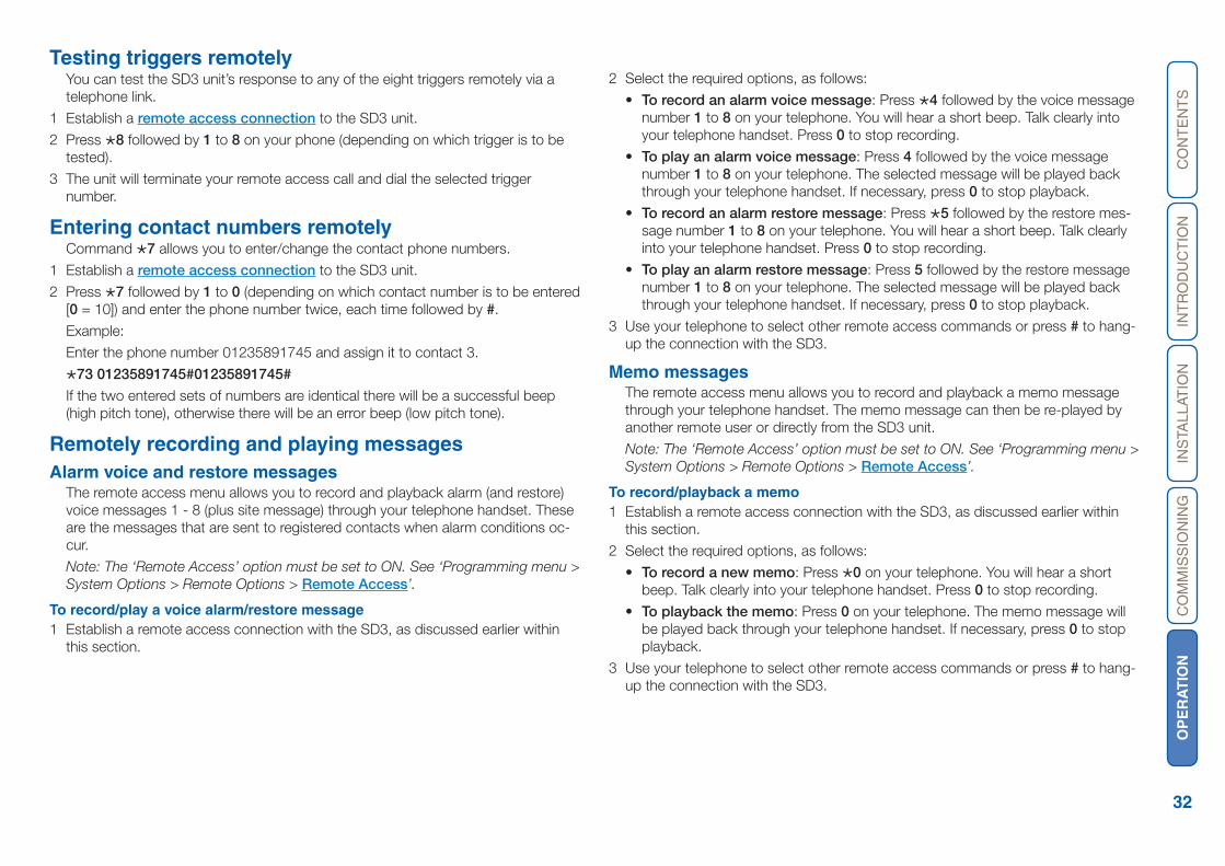
CO
NT
EN
TS
INT
RO
DU
CT
ION
INS
TALL
ATIO
NC
OM
MIS
SIO
NIN
GO
PE
RA
TIO
N
32
Testing triggers remotelyYou can test the SD3 unit’s response to any of the eight triggers remotely via a telephone link.
1 Establish a remote access connection to the SD3 unit.
2 Press *8 followed by 1 to 8 on your phone (depending on which trigger is to be tested).
3 The unit will terminate your remote access call and dial the selected trigger number.
Entering contact numbers remotelyCommand *7 allows you to enter/change the contact phone numbers.
1 Establish a remote access connection to the SD3 unit.
2 Press *7 followed by 1 to 0 (depending on which contact number is to be entered [0 = 10]) and enter the phone number twice, each time followed by #.
Example:
Enter the phone number 01235891745 and assign it to contact 3.
*73 01235891745#01235891745#
If the two entered sets of numbers are identical there will be a successful beep (high pitch tone), otherwise there will be an error beep (low pitch tone).
Remotely recording and playing messagesAlarm voice and restore messages
The remote access menu allows you to record and playback alarm (and restore) voice messages 1 - 8 (plus site message) through your telephone handset. These are the messages that are sent to registered contacts when alarm conditions oc-cur.
Note: The ‘Remote Access’ option must be set to ON. See ‘Programming menu > System Options > Remote Options > Remote Access’.
To record/play a voice alarm/restore message1 Establish a remote access connection with the SD3, as discussed earlier within
this section.
2 Select the required options, as follows:
• To record an alarm voice message: Press *4 followed by the voice message number 1 to 8 on your telephone. You will hear a short beep. Talk clearly into your telephone handset. Press 0 to stop recording.
• To play an alarm voice message: Press 4 followed by the voice message number 1 to 8 on your telephone. The selected message will be played back through your telephone handset. If necessary, press 0 to stop playback.
• To record an alarm restore message: Press *5 followed by the restore mes-sage number 1 to 8 on your telephone. You will hear a short beep. Talk clearly into your telephone handset. Press 0 to stop recording.
• To play an alarm restore message: Press 5 followed by the restore message number 1 to 8 on your telephone. The selected message will be played back through your telephone handset. If necessary, press 0 to stop playback.
3 Use your telephone to select other remote access commands or press # to hang-up the connection with the SD3.
Memo messagesThe remote access menu allows you to record and playback a memo message through your telephone handset. The memo message can then be re-played by another remote user or directly from the SD3 unit.
Note: The ‘Remote Access’ option must be set to ON. See ‘Programming menu > System Options > Remote Options > Remote Access’.
To record/playback a memo1 Establish a remote access connection with the SD3, as discussed earlier within
this section.
2 Select the required options, as follows:
• To record a new memo: Press *0 on your telephone. You will hear a short beep. Talk clearly into your telephone handset. Press 0 to stop recording.
• To playback the memo: Press 0 on your telephone. The memo message will be played back through your telephone handset. If necessary, press 0 to stop playback.
3 Use your telephone to select other remote access commands or press # to hang-up the connection with the SD3.

CO
NT
EN
TS
INT
RO
DU
CT
ION
INS
TALL
ATIO
NC
OM
MIS
SIO
NIN
GO
PE
RA
TIO
N
33
Text Editing Keys Text is programmed in a similar way to mobile phones. Characters are selected by pressing the corresponding key the appropriate number of times (to select a character on the same key, wait for the cursor to automatically advance). The table below shows the keys to use and the characters that are assigned to them:
Key Characters
1 . , ? ! 1 @ “ - & ‘
2 a b c 2 A B C
3 d e f 3 D E F
4 g h i 4 G H I
5 j k l 5 J K L
6 m n o 6 M N O
7 p q r s 7 P Q R S
8 t u v 8 T U V
9 w x y z 9 W X Y Z
0 0 , # *
A C Move cursor left and right
D Delete a character
E Accept text
CO
NT
EN
TS
INT
RO
DU
CT
ION
INS
TALL
ATIO
NC
OM
MIS
SIO
NIN
GO
PE
RA
TIO
N
34
Declaration of Conformance
This product complies with the 1995/5/EC R&TTE Directive. For further details, please see: www.coopersecurity.co.uk
© Cooper Security Ltd. 2006 Part Number 11702491 Issue 1
Every effort has been made to ensure that the contents of this book are correct. However, neither the authors nor Cooper Security Limited accept any liability for loss or damage caused or alleged to be caused directly or indirectly by this book. The contents of this book are subject to change without notice.
Created in the U.K.
Cooper Security Ltd. Security House Vantage Point Business Village Mitcheldean Gloucestershire GL17 0SZ
www.coopersecurity.co.uk
Product Support (UK) Tel: +44 (0) 870 757 5400. Available between:
08:15 and 17:00 Monday to Friday. Product Support Fax: (01594) 545401
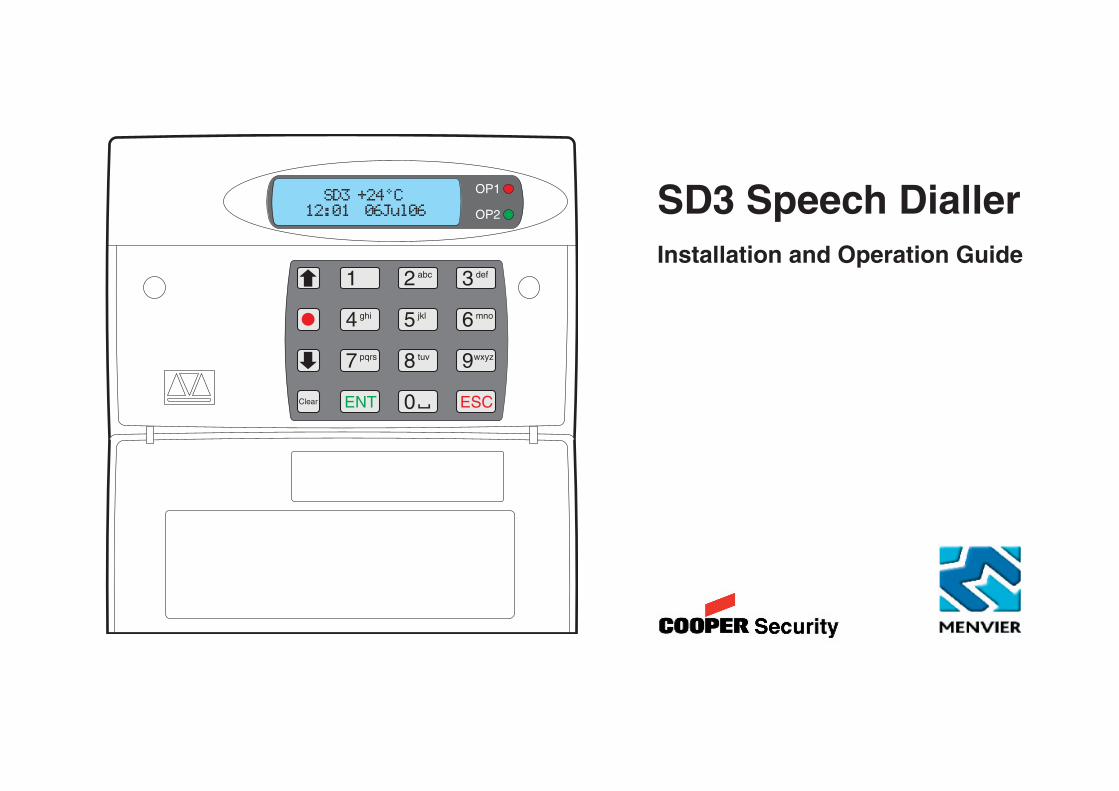
SD3 Speech DiallerInstallation and Operation Guide
OP1
OP2
3
6
9
ESCENTClear
2
5
8
0
1
4
7
def
mno
wxyz
abc
jkl
tuv
ghi
pqrs
SD3 +24°C12:01 06Jul06