Lexium Stepper Motor Drive SD3 - Aandrijftechniek en voor
76
Lexium Stepper Motor Drive SD3 Catalogue June 2008
Transcript of Lexium Stepper Motor Drive SD3 - Aandrijftechniek en voor
LexiumStepper MotorDrive SD3Catalogue
June 2008

Contents Lexium Stepper Motor Drive SD3
Product offerPresentation. . . . . . . . . . . . . . . . . . . . . . . . . . . . . . . . . . . . . . . . . . . . . . . . .Page 2
SD32p stepper motor driveSD326 stepper motor drive
Description . . . . . . . . . . . . . . . . . . . . . . . . . . . . . . . . . . . . . . . . . . . . . . . .Page 4Schemes . . . . . . . . . . . . . . . . . . . . . . . . . . . . . . . . . . . . . . . . . . . . . . . . .Page 5Functions . . . . . . . . . . . . . . . . . . . . . . . . . . . . . . . . . . . . . . . . . . . . . . . . .Page 6Characteristics . . . . . . . . . . . . . . . . . . . . . . . . . . . . . . . . . . . . . . . . . . .Page 12References . . . . . . . . . . . . . . . . . . . . . . . . . . . . . . . . . . . . . . . . . . . . . .Page 14Dimensions . . . . . . . . . . . . . . . . . . . . . . . . . . . . . . . . . . . . . . . . . . . . . .Page 15
SD328 stepper motor drive
Description . . . . . . . . . . . . . . . . . . . . . . . . . . . . . . . . . . . . . . . . . . . . . . .Page 16Schemes . . . . . . . . . . . . . . . . . . . . . . . . . . . . . . . . . . . . . . . . . . . . . . . .Page 18Functions . . . . . . . . . . . . . . . . . . . . . . . . . . . . . . . . . . . . . . . . . . . . . . . .Page 21Characteristics . . . . . . . . . . . . . . . . . . . . . . . . . . . . . . . . . . . . . . . . . . .Page 30References . . . . . . . . . . . . . . . . . . . . . . . . . . . . . . . . . . . . . . . . . . . . . .Page 34Dimensions . . . . . . . . . . . . . . . . . . . . . . . . . . . . . . . . . . . . . . . . . . . . . .Page 35
Mounting and installation recommendations . . . . . . . . . . . . . . . . . . . . . . .Page 36
BRS3 3-phase stepper motorsPresentation. . . . . . . . . . . . . . . . . . . . . . . . . . . . . . . . . . . . . . . . . . . . . . . .Page 40
Characteristics . . . . . . . . . . . . . . . . . . . . . . . . . . . . . . . . . . . . . . . . . . . . .Page 42
Dimensions . . . . . . . . . . . . . . . . . . . . . . . . . . . . . . . . . . . . . . . . . . . . . . . .Page 44
Options . . . . . . . . . . . . . . . . . . . . . . . . . . . . . . . . . . . . . . . . . . . . . . . . . . .Page 46
References . . . . . . . . . . . . . . . . . . . . . . . . . . . . . . . . . . . . . . . . . . . . . . . .Page 50
AccessoriesEMC filter . . . . . . . . . . . . . . . . . . . . . . . . . . . . . . . . . . . . . . . . . . . . . . . . . .Page 52
CANopen fieldbus . . . . . . . . . . . . . . . . . . . . . . . . . . . . . . . . . . . . . . . . . . .Page 54
Modbus fieldbus . . . . . . . . . . . . . . . . . . . . . . . . . . . . . . . . . . . . . . . . . . . . .Page 55
Pulse/direction interface. . . . . . . . . . . . . . . . . . . . . . . . . . . . . . . . . . . . . . .Page 56
Signal interface . . . . . . . . . . . . . . . . . . . . . . . . . . . . . . . . . . . . . . . . . . . . .Page 57
Remote terminal. . . . . . . . . . . . . . . . . . . . . . . . . . . . . . . . . . . . . . . . . . . . .Page 58
Lexium CT PC commissioning software . . . . . . . . . . . . . . . . . . . . . . . . . . .Page 59
Mounting plate . . . . . . . . . . . . . . . . . . . . . . . . . . . . . . . . . . . . . . . . . . . . . .Page 60
Reference value adapter RVA . . . . . . . . . . . . . . . . . . . . . . . . . . . . . . . . . .Page 61
RS422 interface adapter USIC . . . . . . . . . . . . . . . . . . . . . . . . . . . . . . . . . .Page 62
GBX planetary gear . . . . . . . . . . . . . . . . . . . . . . . . . . . . . . . . . . . . . . . . . .Page 63
References – general overview . . . . . . . . . . . . . . . . . . . . . . . . . . . . . . . . .Page 67
AnnexConversion tables . . . . . . . . . . . . . . . . . . . . . . . . . . . . . . . . . . . . . . . . . . .Page 70
b
b
vvvvvv
b
vvvvvv
b
b
b
b
b
b
b
b
b
b
b
b
b
b
b
b
b
b
b
62030-EN_Ver1.0.inddversion: .02
Product offer Lexium Stepper Motor Drive SD3Presentation
SD326 stepper motor drive:Page 4
SD328 stepper motor drive:Page 6
BRS3 3-phase stepper motors:Page 40
Accessories:Page 52
Annex:Page 70
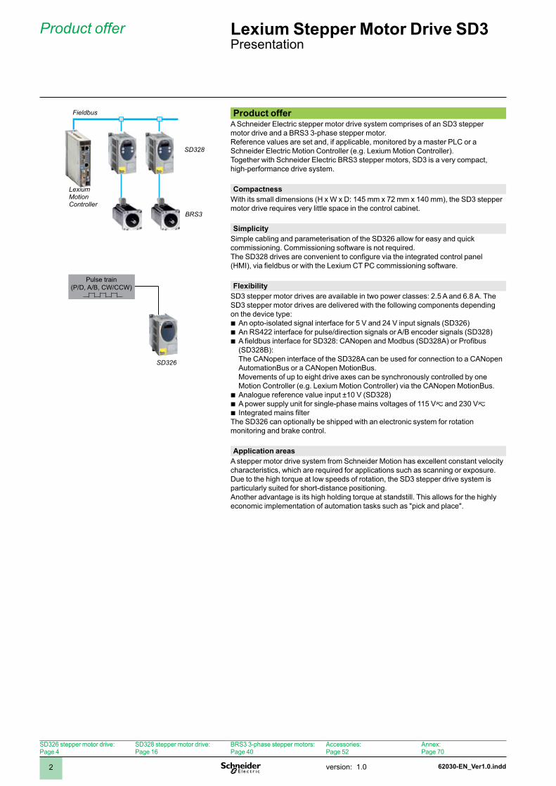
Product offerA Schneider Electric stepper motor drive system comprises of an SD3 stepper motor drive and a BRS3 3-phase stepper motor.Reference values are set and, if applicable, monitored by a master PLC or a Schneider Electric Motion Controller (e.g. Lexium Motion Controller).Together with Schneider Electric BRS3 stepper motors, SD3 is a very compact, high-performance drive system.
CompactnessWith its small dimensions (H x W x D: 45 mm x 72 mm x 40 mm), the SD3 stepper motor drive requires very little space in the control cabinet.
SimplicitySimple cabling and parameterisation of the SD326 allow for easy and quick commissioning. Commissioning software is not required.The SD328 drives are convenient to configure via the integrated control panel (HMI), via fieldbus or with the Lexium CT PC commissioning software.
FlexibilitySD3 stepper motor drives are available in two power classes: 2.5 A and 6.8 A. The SD3 stepper motor drives are delivered with the following components depending on the device type:
An opto-isolated signal interface for 5 V and 24 V input signals (SD326)An RS422 interface for pulse/direction signals or A/B encoder signals (SD328)A fieldbus interface for SD328: CANopen and Modbus (SD328A) or Profibus (SD328B): The CANopen interface of the SD328A can be used for connection to a CANopen AutomationBus or a CANopen MotionBus. Movements of up to eight drive axes can be synchronously controlled by one Motion Controller (e.g. Lexium Motion Controller) via the CANopen MotionBus.Analogue reference value input ±0 V (SD328)A power supply unit for single-phase mains voltages of 5 Vz and 230 VzIntegrated mains filter
The SD326 can optionally be shipped with an electronic system for rotation monitoring and brake control.
bbb
bbb
Application areasA stepper motor drive system from Schneider Motion has excellent constant velocity characteristics, which are required for applications such as scanning or exposure. Due to the high torque at low speeds of rotation, the SD3 stepper drive system is particularly suited for short-distance positioning.Another advantage is its high holding torque at standstill. This allows for the highly economic implementation of automation tasks such as "pick and place".
Pulse train(P/D, A/B, CW/CCW)
Fieldbus
LexiumMotion Controller
SD328
SD326
BRS3
version: .0 62030-EN_Ver1.0.indd 3
Product offer (continued) Lexium Stepper Motor Drive SD3Presentation
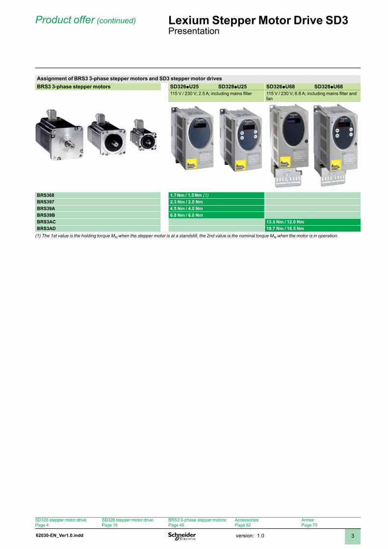
Assignment of BRS3 3-phase stepper motors and SD3 stepper motor drivesBRS3 3-phase stepper motors SD326pU25 SD328pU25 SD326pU68 SD328pU68
115 V / 230 V; 2.5 A; including mains filter 115 V / 230 V; 6.8 A; including mains filter and fan
BRS368 1.7 Nm / 1.5 Nm (1)BRS397 2.3 Nm / 2.0 NmBRS39A 4.5 Nm / 4.0 NmBRS39B 6.8 Nm / 6.0 NmBRS3AC 13.5 Nm / 12.0 NmBRS3AD 19.7 Nm / 16.5 Nm
(1) The 1st value is the holding torque MH when the stepper motor is at a standstill, the 2nd value is the nominal torque MN when the motor is in operation.
SD326 stepper motor drive:Page 4
SD328 stepper motor drive:Page 6
BRS3 3-phase stepper motors:Page 40
Accessories:Page 52
Annex:Page 70
62031-EN_Ver1.0.inddversion: .04
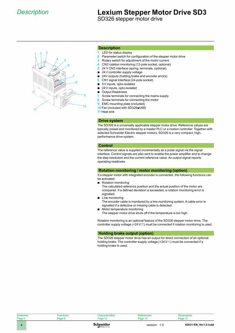
Description1 LED for status display2 Parameter switch for configuration of the stepper motor drive3 Rotary switch for adjustment of the motor current4 CN2 rotation monitoring (12-pole socket, optional)5 24 V CN3 interface (spring terminals, optional)
24 V controller supply voltage24V outputs (holding brake and encoder errors)
6 CN1 signal interface (24-pole socket)5 V inputs, opto-isolated24 V inputs, opto-isolatedOutput Readiness
7 Screw terminals for connecting the mains supply8 Screw terminals for connecting the motor9 EMC mounting plate (included)10 Fan (included with SD326pU68)11 Heat sink
bb
bbb
Drive systemThe SD326 is a universally applicable stepper motor drive. Reference values are typically preset and monitored by a master PLC or a motion controller. Together with selected Schneider Electric stepper motors, SD326 is a very compact, high-performance drive system.
ControlThe reference value is supplied incrementally as a pulse signal via the signal interface. Control signals are also sent to enable the power amplifier and to change the step resolution and the current reference value. An output signal reports operating readiness.
Rotation monitoring / motor monitoring (option)If a stepper motor with integrated encoder is connected, the following functions can be activated:
Rotation monitoring The calculated reference position and the actual position of the motor are compared. If a defined deviation is exceeded, a rotation monitoring error is signalled.Line monitoring The encoder cable is monitored by a line monitoring system. A cable error is signalled if a defective or missing cable is detected.Motor temperature monitoring The stepper motor drive shuts off if the temperature is too high.
Rotation monitoring is an optional feature of the SD326 stepper motor drive. The controller supply voltage (+24 Vc) must be connected if rotation monitoring is used.
b
b
b
Holding brake output (option)The SD326 stepper motor drive has an output for direct connection of an optional holding brake. The controller supply voltage (+24 Vc) must be connected if a holding brake is used.
Description Lexium Stepper Motor Drive SD3 SD326 stepper motor drive
2 3
4 56
7
8
9
0
Schemes:Page 5
Functions:Page 6
Characteristics:Page 2
References:Page 4
Dimensions:Page 5
6203-EN_Ver.0.indd version: .0 5
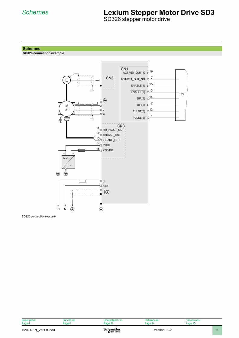
SchemesSD326 connection example
CN3
CN1
NL1
+-24Vc
~
12131415
W
U
VM3~
L1
N/L2
ACTIVE1_OUT_C
3
14
2
PULSE(5)
DIR(5)
ENABLE(5)
E CN2
5V
7
15
19
11 RM_FAULT_OUT
+BRAKE_OUT
0VDC
+24VDC
-BRAKE_OUT
ACTIVE1_OUT_NO
PULSE(5)
DIR(5)
ENABLE(5)
13
1
SD326 connection example
Schemes Lexium Stepper Motor Drive SD3 SD326 stepper motor drive
Description:Page 4
Functions:Page 6
Characteristics:Page 2
References:Page 4
Dimensions:Page 5
62032-EN_Ver1.0.inddversion: .06
Functions Lexium Stepper Motor Drive SD3SD326 stepper motor drive
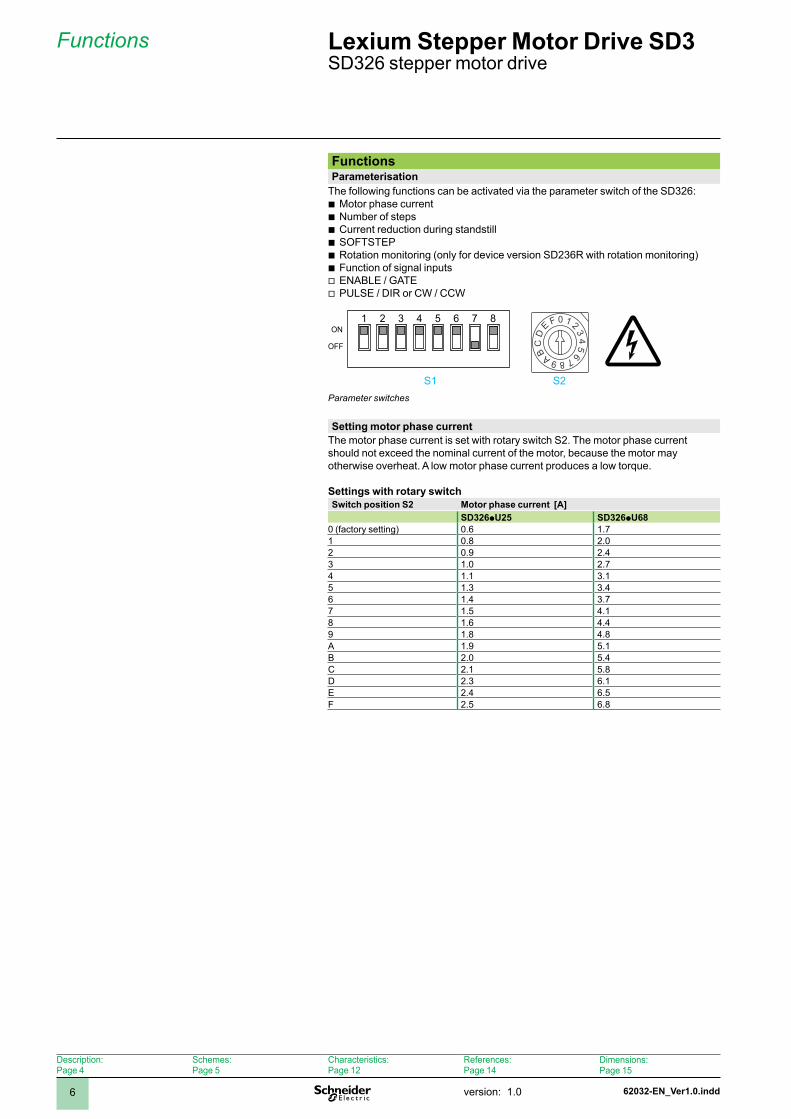
FunctionsParameterisation
The following functions can be activated via the parameter switch of the SD326:Motor phase currentNumber of stepsCurrent reduction during standstill SOFTSTEPRotation monitoring (only for device version SD236R with rotation monitoring)Function of signal inputs ENABLE / GATEPULSE / DIR or CW / CCW
bbbbbbvv
1 2 3 4 5 6 7 8 0 1 2 34
56789AB
CD
E FON
OFF
Parameter switches
Setting motor phase currentThe motor phase current is set with rotary switch S2. The motor phase current should not exceed the nominal current of the motor, because the motor may otherwise overheat. A low motor phase current produces a low torque.
Settings with rotary switchSwitch position S2 Motor phase current [A]
SD326pU25 SD326pU680 (factory setting) 0.6 .7 0.8 2.02 0.9 2.43 .0 2.74 . 3.5 .3 3.46 .4 3.77 .5 4.8 .6 4.49 .8 4.8A .9 5.B 2.0 5.4C 2. 5.8D 2.3 6.E 2.4 6.5F 2.5 6.8
S S2
Description:Page 4
Schemes:Page 5
Characteristics:Page 2
References:Page 4
Dimensions:Page 5
62032-EN_Ver1.0.indd version: .0 7
Functions (continued) Lexium Stepper Motor Drive SD3 SD326 stepper motor drive
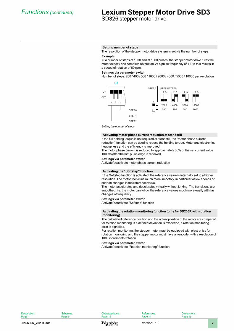
Setting number of stepsThe resolution of the stepper motor drive system is set via the number of steps. ExampleAt a number of steps of 1000 and at 1000 pulses, the stepper motor drive turns the motor exactly one complete revolution. At a pulse frequency of 1 kHz this results in a speed of rotation of 60 rpm.Settings via parameter switchNumber of steps: 200 / 400 / 500 / 1000 / 2000 / 4000 / 5000 / 10000 per revolution
ON
OFF
STEP0
STEP1
STEP2
1 2 3
STEP2 STEP1/STEP0
2000
200
4000
400
5000
500
10000
1000
2 32 32 3 2 3
1
Setting the number of steps
Activating motor phase current reduction at standstillIf the full holding torque is not required at standstill, the "motor phase current reduction" function can be used to reduce the holding torque. Motor and electronics heat up less and the efficiency is improved.The motor phase current is reduced to approximately 60% of the set current value 00 ms after the last pulse edge is received.Settings via parameter switchActivate/deactivate motor phase current reduction
Activating the “Softstep” functionIf the Softstep function is activated, the reference value is internally set to a higher resolution. The motor then runs much more smoothly, in particular at low speeds or sudden changes in the reference value.The motor accelerates and decelerates virtually without jerking. The transitions are smoothed, i.e. the motor can follow the reference values much more easily with fast changes of frequency.Settings via parameter switchActivate/deactivate "Softstep" function
Activating the rotation monitoring function (only for SD236R with rotation monitoring)
The calculated reference position and the actual position of the motor are compared for rotation monitoring. If a defined deviation is exceeded, a rotation monitoring error is signalled.For rotation monitoring, the stepper motor must be equipped with electronics for rotation monitoring and the stepper motor must have an encoder with a resolution of 000 increments/rotation. Settings via parameter switchActivate/deactivate “Rotation monitoring” function
S
Description:Page 4
Schemes:Page 5
Characteristics:Page 2
References:Page 4
Dimensions:Page 5
62032-EN_Ver1.0.inddversion: .08
Functions (continued) Lexium Stepper Motor Drive SD3 SD326 stepper motor drive
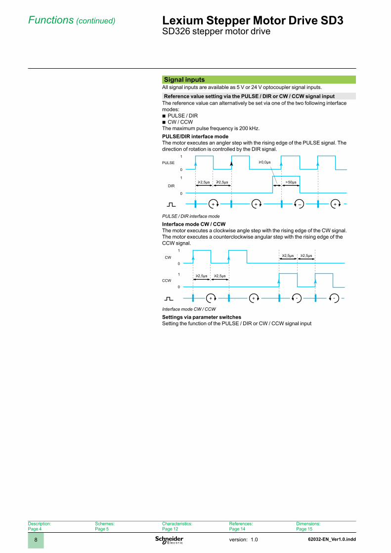
Signal inputsAll signal inputs are available as 5 V or 24 V optocoupler signal inputs.
Reference value setting via the PULSE / DIR or CW / CCW signal inputThe reference value can alternatively be set via one of the two following interface modes:
PULSE / DIRCW / CCW
The maximum pulse frequency is 200 kHz.PULSE/DIR interface modeThe motor executes an angler step with the rising edge of the PULSE signal. The direction of rotation is controlled by the DIR signal.
0
1
0
1
+ + +–
PULSE
DIRu2,5µs u2,5µs >50µs
u0,0µs
PULSE / DIR interface mode
Interface mode CW / CCWThe motor executes a clockwise angle step with the rising edge of the CW signal. The motor executes a counterclockwise angular step with the rising edge of the CCW signal.
0
1
0
1
+ + - -
CW
CCW
u2,5µs u2,5µs
u2,5µs u2,5µs
Interface mode CW / CCW
Settings via parameter switchesSetting the function of the PULSE / DIR or CW / CCW signal input
bb
Description:Page 4
Schemes:Page 5
Characteristics:Page 2
References:Page 4
Dimensions:Page 5
62032-EN_Ver1.0.indd version: .0 9
Functions (continued) Lexium Stepper Motor Drive SD3 SD326 stepper motor drive
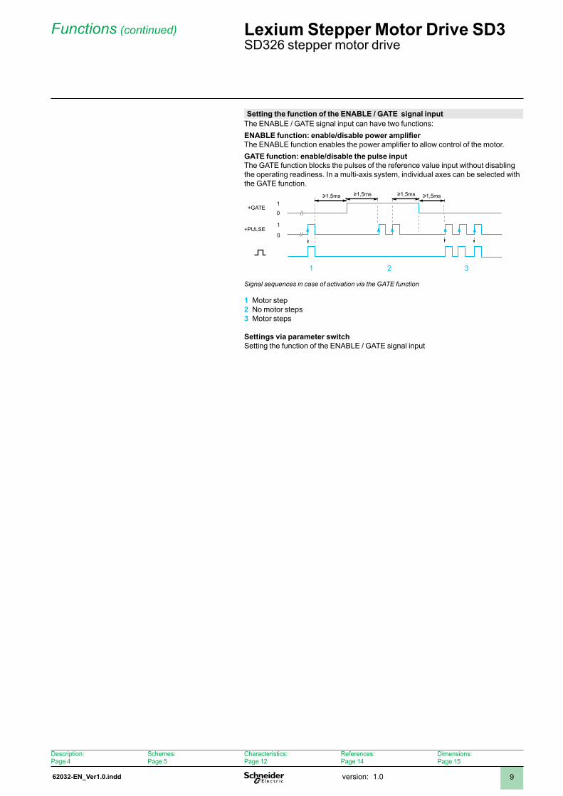
Setting the function of the ENABLE / GATE signal inputThe ENABLE / GATE signal input can have two functions:ENABLE function: enable/disable power amplifierThe ENABLE function enables the power amplifier to allow control of the motor.GATE function: enable/disable the pulse inputThe GATE function blocks the pulses of the reference value input without disabling the operating readiness. In a multi-axis system, individual axes can be selected with the GATE function.
0
1+PULSE
0
1u1,5msu1,5ms u1,5msu1,5ms
+GATE
Signal sequences in case of activation via the GATE function
Motor stepNo motor stepsMotor steps
Settings via parameter switchSetting the function of the ENABLE / GATE signal input
1 2 3
2 3
Description:Page 4
Schemes:Page 5
Characteristics:Page 2
References:Page 4
Dimensions:Page 5
62032-EN_Ver1.0.inddversion: .00
Functions (continued) Lexium Stepper Motor Drive SD3 SD326 stepper motor drive
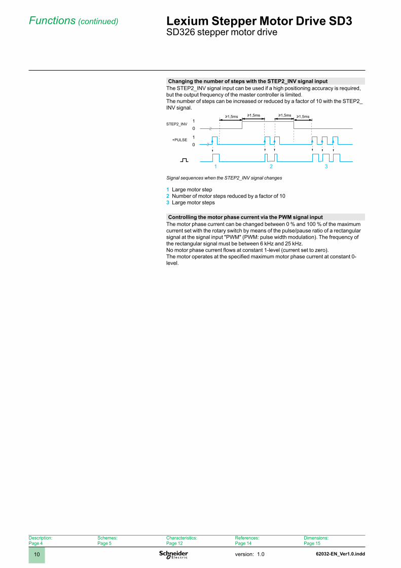
Changing the number of steps with the STEP2_INV signal inputThe STEP2_INV signal input can be used if a high positioning accuracy is required, but the output frequency of the master controller is limited.The number of steps can be increased or reduced by a factor of 10 with the STEP2_INV signal.
01+PULSE
STEP2_INV01
u1,5msu1,5ms u1,5msu1,5ms
Signal sequences when the STEP2_INV signal changes
Large motor stepNumber of motor steps reduced by a factor of 10Large motor steps
1 2 3
Controlling the motor phase current via the PWM signal inputThe motor phase current can be changed between 0 % and 100 % of the maximum current set with the rotary switch by means of the pulse/pause ratio of a rectangular signal at the signal input "PWM" (PWM: pulse width modulation). The frequency of the rectangular signal must be between 6 kHz and 25 kHz.No motor phase current flows at constant 1-level (current set to zero).The motor operates at the specified maximum motor phase current at constant 0-level.
2 3
Description:Page 4
Schemes:Page 5
Characteristics:Page 2
References:Page 4
Dimensions:Page 5
62032-EN_Ver1.0.indd version: .0
Functions (continued) Lexium Stepper Motor Drive SD3 SD326 stepper motor drive
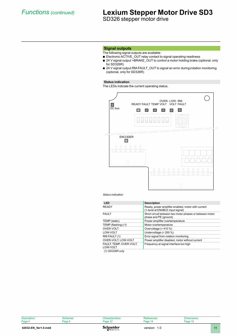
Signal outputsThe following signal outputs are available:
Electronic ACTIVE_OUT relay contact to signal operating readiness24 V signal output +BRAKE_OUT to control a motor holding brake (optional, only for SD326R)24 V signal output RM-FAULT_OUT to signal an error during rotation monitoring (optional, only for SD326R)
bb
b
Status indicationThe LEDs indicate the current operating status.
0 1 2
34
56789A
BC
D
E F
Status indication
LED DescriptionREADY Ready, power amplifier enabled, motor with current
(-level at ENABLE input signal)FAULT Short circuit between two motor phases or between motor
phase and PE (ground)TEMP (static) Power amplifier overtemperatureTEMP (flashing) (1) Motor overtemperatureOVER-VOLT Overvoltage (> 40 %)LOW-VOLT Undervoltage (< 200 %)RM-FAULT (1) Error signal from rotation monitoringOVER-VOLT, LOW-VOLT Power amplifier disabled, motor without currentFAULT, TEMP, OVER-VOLT, LOW-VOLT
Frequency at signal interface too high
(1) SD326R only
DC busREADY FAULT TEMP
OVER-VOLT
LOW-VOLT
RM-FAULT
ENCODER
Description:Page 4
Schemes:Page 5
Characteristics:Page 2
References:Page 4
Dimensions:Page 5
62033-EN_Ver1.0.inddversion: .02
Characteristics Lexium Stepper Motor Drive SD3 SD326 stepper motor drive
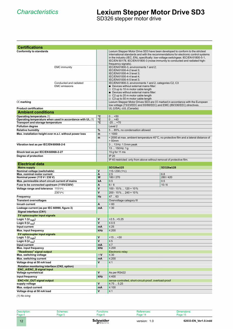
CertificationsConformity to standards Lexium Stepper Motor Drive SD3 have been developed to conform to the strictest
international standards and with the recommendations for electronic control systems in the industry (IEC, EN), specifically: low-voltage switchgear, IEC/EN 61800-5-1, IEC/EN 5078, IEC/EN 6800-3 (noise immunity to conducted and radiated high-frequency signals).
EMC immunity IEC/EN 6800-3, environments and 2;IEC/EN 6000-4-2 level 3;IEC/EN 6000-4-3 level 3;IEC/EN 6000-4-4 level 4;IEC/EN 6000-4-5 level 3;
Conducted and radiated EMC emissions
IEC/EN 6800-3, environments and 2, categories C2, C3Devices without external mains filter:C3 up to 10 m motor cable lengthDevices without external mains filter: C2 up to 20 m motor cable lengthC3 up to 50 m motor cable length
bvbvv
e marking Lexium Stepper Motor Drives SD3 are e marked in accordance with the European low voltage (73/23/EEC and 93/68/EEC) and EMC (89/336/EEC) directives.
Product certification UL (USA), cUL (Canada)Ambient conditions
Operating temperature (1) °C 0 ... +50Operating temperature when used in accordance with UL (1) °C 0 ... +40Transport and storage temperature °C -25 ... +70 Pollution degree Level 2Relative humidity % 5 ... 85%, no condensation allowedMax. installation height over m.s.l. without power loss m < 000
m < 2000 at max. ambient temperature 40°C, no protective film and a lateral distance of > 50mm
Vibration test as per IEC/EN 60068-2-6 3 ... 13 Hz: 1.5 mm peak13 ... 150 Hz: 1 g
Shock test as per IEC/EN 60068-2-27 5 g for msDegree of protection IP 20
IP 40 restricted: only from above without removal of protective film.
Electrical dataMains supply SD326pU25 SD326pU28
Nominal voltage (switchable) V 5 / 230 (z)Max. nominal motor current A 2.5 6.8Nominal power (115 V / 230 V) W 80 / 270 280 / 420Max. permissible short circuit current of mains kA 0.5 0.5Fuse to be connected upstream (115V/230V) A 6 / 6 0 / 6Voltage range and tolerance 5 Vz V 00 - 5 % ... 20 + 0 %
230 Vz V 200 - 5 % ... 240 + 0 %Frequency Hz 47 ... 63Transient overvoltages Overvoltage category IIIInrush current A < 60Leakage current (as per IEC 60990, figure 3) mA < 30Signal interface (CN1)5 V optocoupler input signals
Logic 1 (U high) V +2.5...+5.25Logic 0 (U low) V y 0.5Input current mA y 25Max. input frequency kHz y 2005 V optocoupler input signals
Logic 1 (U high) V +5 ... +30Logic 0 (U low) V y 5Input current mA y 7Max. input frequency kHz y 200"Readiness" signal output Electronic relay
Max. switching voltage cV y 30Max. switching current mA y 200 Voltage drop at 50 mA load V y Rotation monitoring interface (CN2, option)ENC_A/ENC_B signal input
Voltage symmetrical V As per RS422input frequency kHz y 400ENC+5V_OUT signal output sense-controlled, short-circuit-proof, overload-proof
supply voltage V 4.75 ... 5.25Max. output current mA y 00 Voltage drop at 50 mA load V y
(1) No icing
Description:Page 4
Schemes:Page 5
Functions:Page 6
References:Page 4
Dimensions:Page 5

62033-EN_Ver1.0.indd version: .0 3
Characteristics (continued) Lexium Stepper Motor Drive SD3 SD326 stepper motor drive
Electrical data24 V interface (CN3, option)24 V control voltage As per IEC 63-2
Input voltage V 24 -5% / +20%Current consumption A y 0.2Residual ripple % y 524 V output signals As per IEC 63-2
Output voltage V y 30 Max. Switching current RM-FAULT_OUT V y 50 Max. switching current +BRAKE_OUT A y .7Voltage drop at 50 mA load V y Mechanical data
SD326pU25 SD326pU28Dimensions (W x H x D) mm 72 x 45 x 40Mass kg . .2Type of cooling Convection FanMax. speed of rotation of motor rpm 3000
Description:Page 4
Schemes:Page 5
Functions:Page 6
References:Page 4
Dimensions:Page 5

2
1
3
4
5
6
7
8
9
10
2
1
3
4
5
6
7
8
9
10
62034-EN_Ver1.0.inddversion: .04
References Lexium Stepper Motor Drive SD3 SD326 stepper motor drive
Order codeExample: SD3 26 D U25 S2
Product designationSD3 = stepper motor drive 3-phase
SD3 26 D U25 S2
Product type26 = standard stepper motor drive
SD3 26 D U25 S2
InterfacesD = pulse/direction without rotation monitoringR = pulse/direction with rotation monitoring and holding brake connection
SD3 26 D U25 S2
Max. nominal motor currentU25 = 2.5 AU68 = 6.8 A
SD3 26 D U25 S2
Power amplifier supply voltageS2 = ∿, 5 Vz / 230 Vz (switchable)
SD3 26 D U25 S2
SD326 stepper motor drive
Description:Page 4
Schemes:Page 5
Functions:Page 6
Characteristics:Page 2
Dimensions:Page 5
2
1
3
4
5
6
7
8
9
10
2
1
3
4
5
6
7
8
9
10
62034-EN_Ver1.0.indd version: .0 5
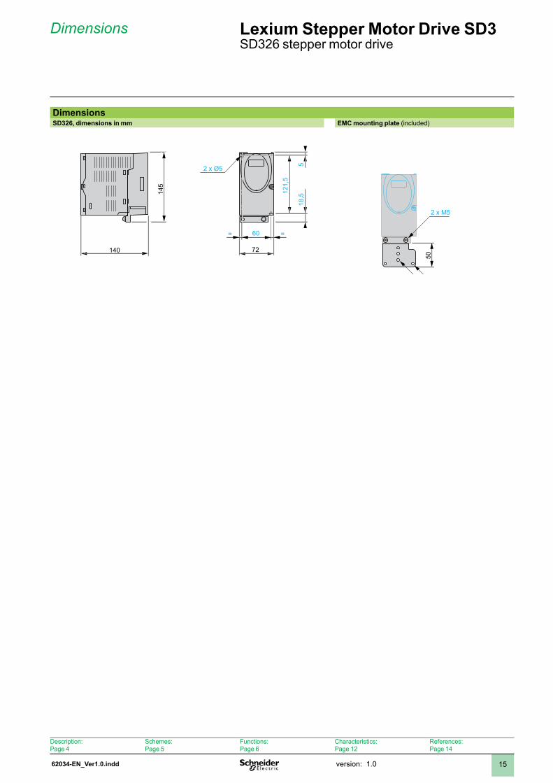
Dimensions Lexium Stepper Motor Drive SD3 SD326 stepper motor drive
DimensionsSD326, dimensions in mm EMC mounting plate (included)
2 x Ø5
140
60
121,
5
518
,5145
= =
72
50
4 x M4M5t
2 x M5
Description:Page 4
Schemes:Page 5
Functions:Page 6
Characteristics:Page 2
References:Page 4

62035-EN_Ver1.0.inddversion: .06
Description Lexium Stepper Motor Drive SD3 SD328 stepper motor drive
DescriptionComponents and interfaces
1 12-pole socket CN2 for motor encoder2 I/O signal connection CN (spring terminals)
Analogue reference value input ±0 V in oscillator operating mode (SD328A only)CANopen for fieldbus control (SD328A only)Profibus for fieldbus control (SD328B only)Eight digital inputs/outputs. The assignment depends on the selected operating mode.
3 Connection CN3 for 24 V power supply and holding brake4 RJ45 socket CN4 for connection of:
Fieldbus: Modbus or CANopen (SD328A only)PC with Lexium CT commissioning softwareRemote terminal
5 10-pole socket CN5 for input of pulse/direction or A/B encoder signals in "electronic gear" operating mode
6 Screw terminals for connecting the mains supply7 Screw terminals for connecting the motor and external braking resistors8 EMC mounting plate9 Fan (SD328pU68 only)10 Base for fastening of the EMC mounting plate11 Heat sink
b
bbb
bbb
Drive systemThe SD328 is a universally applicable stepper motor drive.Reference values are typically preset and monitored by a master PLC or a Schneider Electric Motion Controller, e.g. LMC.Together with selected Schneider Electric stepper motors, the unit is a very compact, high-performance drive system.
ControlReference values are supplied via:
CANopen, Modbus (SD328A) or Profibus (SD328B): The CANopen interface of the SD328A can be used for connection of a CANopen AutomationBus or CANopen MotionBus. Movements of up to eight drive axes can be synchronously controlled by one Motion Controller (e.g. Lexium Motion Controller) via the CANopen MotionBus.±10 V analogue signals for "Oscillator" operating mode (SD328A)Pulse/direction signals or A/B encoder signals for implementing an electronic gear
b
bb
Rotation monitoring / motor monitoringIf a stepper motor with integrated encoder is connected to the stepper motor drive, the following functions can be activated:
Rotation monitoring The calculated reference position and the actual position of the motor are compared. If a defined deviation is exceeded, a rotation monitoring error is signalled. Line monitoring: A cable error is signalled if a defective or missing cable is detected.Motor temperature monitoring: The device shuts off if the motor temperature is too high.
b
b
b
Holding brake outputThe stepper motor drive has an output for direct connection of an optional holding brake.
"Safe Torque Off" safety function (Power Removal "PWRR")The integrated "Safe Torque Off" safety function enables a category 0 or 1 stop as per IEC/EN 60204- without external power contactors. The supply voltage does not have to be interrupted. This reduces the system costs and response times.The drive system fulfils the requirements of IEC 61508 SIL 2 as well as of ISO 13849-1, performance level "d" (PL d), and IEC/EN 61800-5-2 ("STO").
2
1 435
6
7
8
911
10
Schemes:Page 8
Functions:Page 2
Characteristics:Page 30
References:Page 34
Dimensions:Page 35
62035-EN_Ver1.0.indd version: .0 7
Description (continued) Lexium Stepper Motor Drive SD3 SD328 stepper motor drive
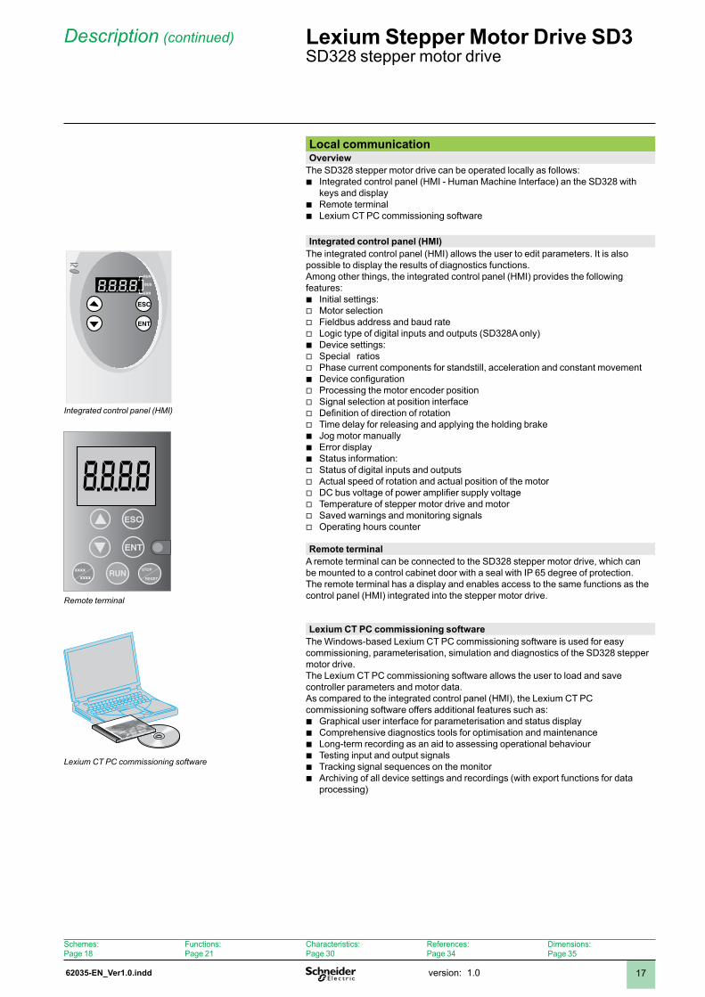
Local communicationOverview
The SD328 stepper motor drive can be operated locally as follows:Integrated control panel (HMI - Human Machine Interface) an the SD328 with keys and displayRemote terminalLexium CT PC commissioning software
b
bb
Integrated control panel (HMI)The integrated control panel (HMI) allows the user to edit parameters. It is also possible to display the results of diagnostics functions.Among other things, the integrated control panel (HMI) provides the following features:
Initial settings:Motor selectionFieldbus address and baud rateLogic type of digital inputs and outputs (SD328A only)Device settings:Special ratiosPhase current components for standstill, acceleration and constant movementDevice configurationProcessing the motor encoder positionSignal selection at position interfaceDefinition of direction of rotationTime delay for releasing and applying the holding brakeJog motor manuallyError displayStatus information:Status of digital inputs and outputsActual speed of rotation and actual position of the motorDC bus voltage of power amplifier supply voltageTemperature of stepper motor drive and motorSaved warnings and monitoring signalsOperating hours counter
bvvvbvvbvvvvbbbvvvvvv
Remote terminalA remote terminal can be connected to the SD328 stepper motor drive, which can be mounted to a control cabinet door with a seal with IP 65 degree of protection.The remote terminal has a display and enables access to the same functions as the control panel (HMI) integrated into the stepper motor drive.
Lexium CT PC commissioning softwareThe Windows-based Lexium CT PC commissioning software is used for easy commissioning, parameterisation, simulation and diagnostics of the SD328 stepper motor drive.The Lexium CT PC commissioning software allows the user to load and save controller parameters and motor data.As compared to the integrated control panel (HMI), the Lexium CT PC commissioning software offers additional features such as:
Graphical user interface for parameterisation and status displayComprehensive diagnostics tools for optimisation and maintenanceLong-term recording as an aid to assessing operational behaviourTesting input and output signalsTracking signal sequences on the monitorArchiving of all device settings and recordings (with export functions for data processing)
bbbbbb
8.8.8.8
RUNSTOP
RESETxxxx
xxxx
ESC
ENT
8.8.8.8ESC
ENT
RUN
ERR
BUS
Integrated control panel (HMI)
Remote terminal
Lexium CT PC commissioning software
Schemes:Page 8
Functions:Page 2
Characteristics:Page 30
References:Page 34
Dimensions:Page 35
62036-EN_Ver1.0.inddversion: .08
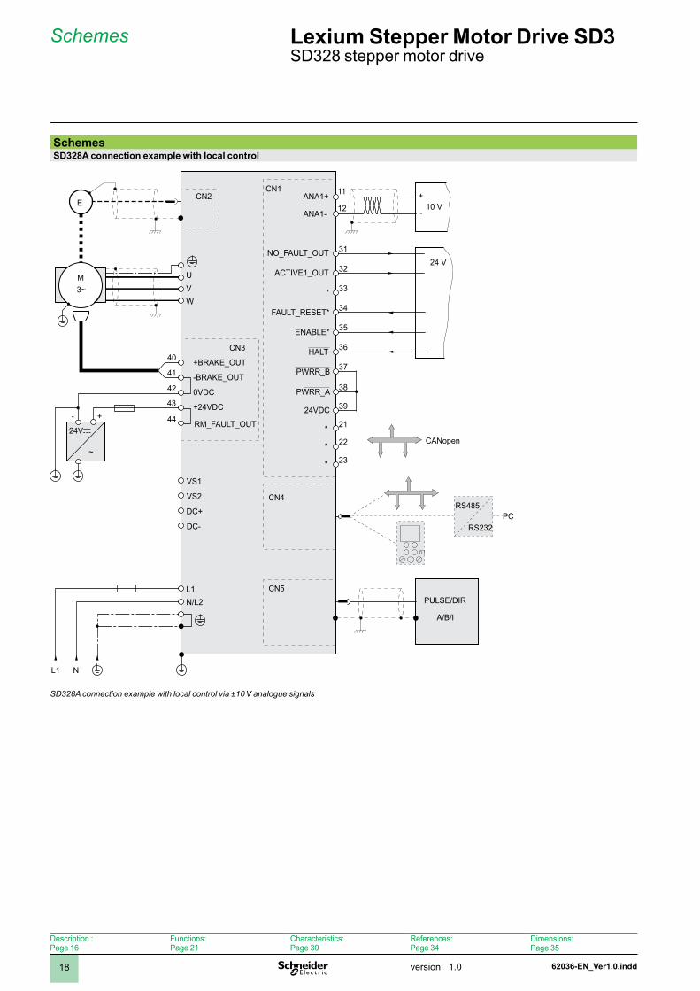
Schemes Lexium Stepper Motor Drive SD3 SD328 stepper motor drive
SchemesSD328A connection example with local control
CN3
CN1
+-
24Vc
~
40
41
42
43
W
UV
M3~
ECN2
44 RM_FAULT_OUT
+BRAKE_OUT
0VDC
+24VDC
-BRAKE_OUT
PULSE/DIR
A/B/I
CN4
CN5
ACTIVE1_OUT
NO_FAULT_OUT
*
24VDC
31
32
33
34
35
36
37
38
39
HALT
FAULT_RESET*
ENABLE*
23
21
22
24 V
*
*
*CANopen
10 V+
-
11
12ANA1-
ANA1+
VS1
VS2
DC+
DC-
NL1
L1N/L2
RS485
RS232PC
PWRR_B
PWRR_A
SD328A connection example with local control via ±10 V analogue signals
Description :Page 6
Functions:Page 2
Characteristics:Page 30
References:Page 34
Dimensions:Page 35
62036-EN_Ver1.0.indd version: .0 9
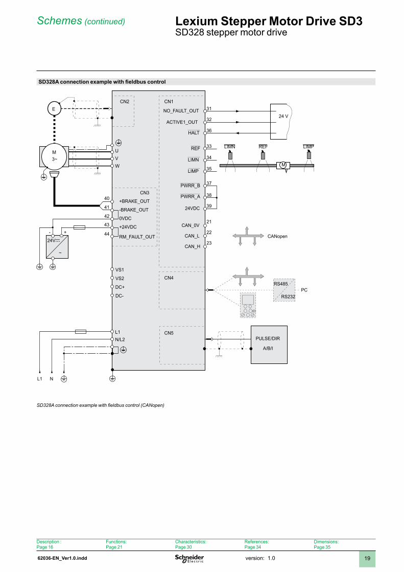
SD328A connection example with fieldbus control
CN3
CN1
+-
~
40
41
42
43
W
UV
M3~
ECN2
44 RM_FAULT_OUT
+BRAKE_OUT
0VDC
+24VDC
-BRAKE_OUT
PULSE/DIR
A/B/I
CN4
CN5
ACTIVE1_OUT
NO_FAULT_OUT
PWRR_B
PWRR_A
24VDC
31
32
33
34
35
36
37
38
39
HALT
23
21
22
VS1
VS2
DC+
DC-
NL1
L1N/L2
RS485
RS232PC
REF
M
LIMN LIMPREF
LIMN
LIMP
24Vc
24 V
CAN_0V
CAN_L
CAN_H
CANopen
SD328A connection example with fieldbus control (CANopen)
Schemes (continued) Lexium Stepper Motor Drive SD3 SD328 stepper motor drive
Description :Page 6
Functions:Page 2
Characteristics:Page 30
References:Page 34
Dimensions:Page 35
62036-EN_Ver1.0.inddversion: .020
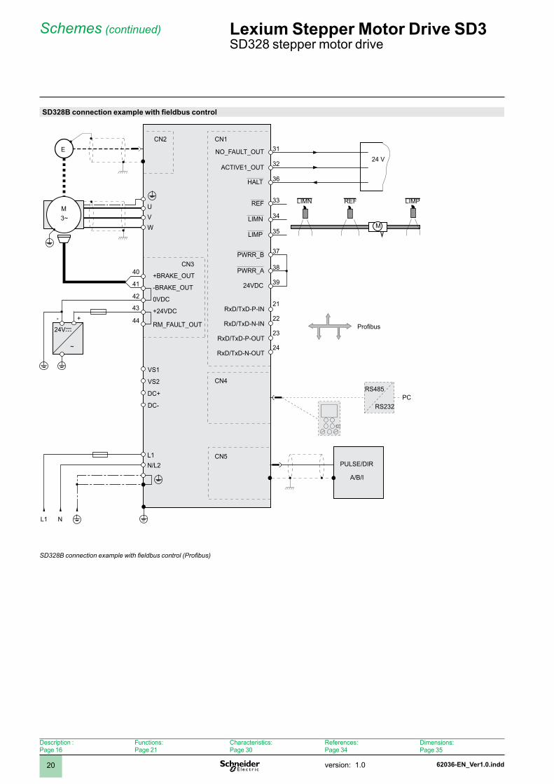
SD328B connection example with fieldbus control
CN3
CN1
+-
~
40
41
42
43
W
UV
M3~
ECN2
44 RM_FAULT_OUT
+BRAKE_OUT
0VDC
+24VDC
-BRAKE_OUT
PULSE/DIR
A/B/I
CN4
CN5
ACTIVE1_OUT
NO_FAULT_OUT
24VDC
31
32
33
34
35
36
37
38
39
HALT
23
21
22
VS1
VS2
DC+
DC-
NL1
L1N/L2
RS485
RS232PC
REF
M
LIMN LIMPREF
LIMN
LIMP
RxD/TxD-P-IN
RxD/TxD-N-IN
RxD/TxD-P-OUT
RxD/TxD-N-OUT
Profibus
24
24Vc
24 V
PWRR_B
PWRR_A
SD328B connection example with fieldbus control (Profibus)
Schemes (continued) Lexium Stepper Motor Drive SD3 SD328 stepper motor drive
Description :Page 6
Functions:Page 2
Characteristics:Page 30
References:Page 34
Dimensions:Page 35
62036-EN_Ver1.0.indd version: .0 2
Functions
Commissioning functionsThe following tools can be used to commission the device:
Integrated control panel (HMI)Remote terminalLexium CT PC commissioning softwareFieldbus
Two important commissioning functions of the SD328A are explained below. Please refer to the documentation for the stepper motor drive for a detailed description of the commissioning functions.
bbbb
Control via fieldbus or local (SD328A only)When the stepper motor drive is started for the first time, the user must specify whether access and parameterisation will be via local control or via fieldbus. This setting can only be modified by restoring the factory settings. The operating modes available for the stepper motor drive also depend on this setting.
In the case of local control, the integrated control panel (HMI), the remote terminal (equivalent to the integrated control panel in terms of functions) or the Lexium CT PC commissioning software is used for parameterisation. Movements are then preset with a ±0 V analogue signal or with RS422 signals (pulse/direction signals). Limit switches or reference switches cannot be connected in the case of local control.
In fieldbus control mode, all communication takes place via fieldbus commands.
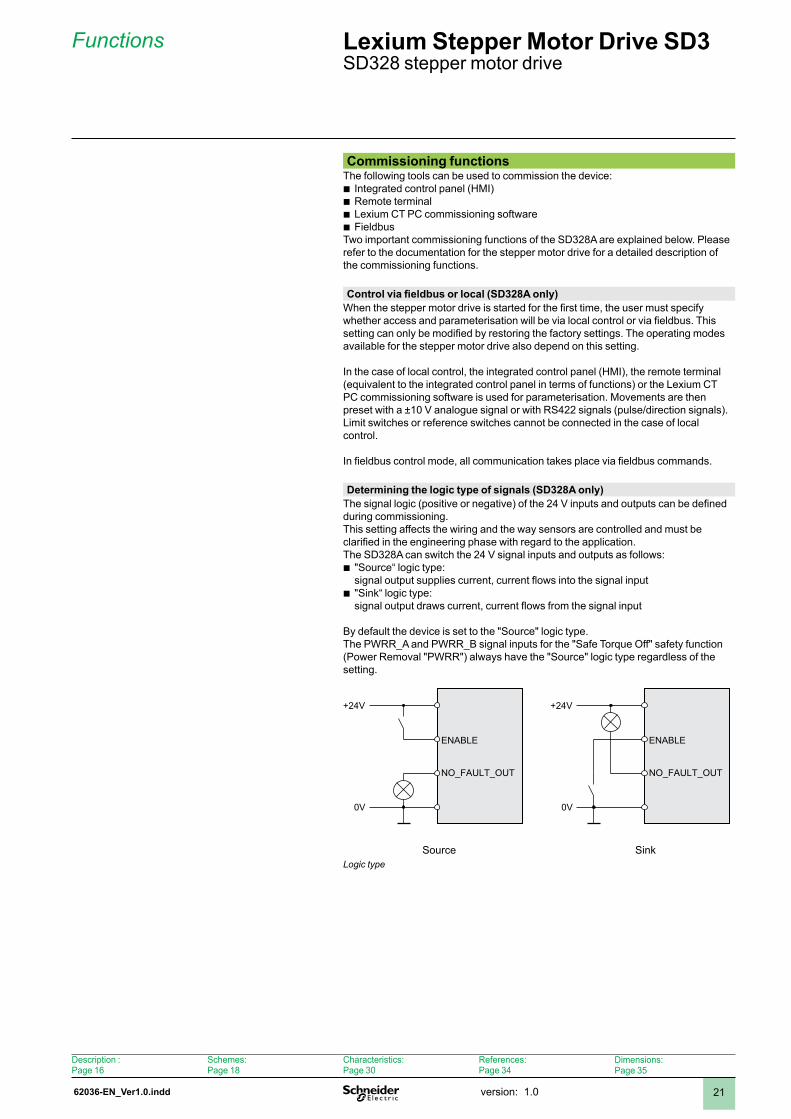
Determining the logic type of signals (SD328A only)The signal logic (positive or negative) of the 24 V inputs and outputs can be defined during commissioning.This setting affects the wiring and the way sensors are controlled and must be clarified in the engineering phase with regard to the application.The SD328A can switch the 24 V signal inputs and outputs as follows:
"Source“ logic type: signal output supplies current, current flows into the signal input"Sink“ logic type: signal output draws current, current flows from the signal input
By default the device is set to the "Source" logic type. The PWRR_A and PWRR_B signal inputs for the "Safe Torque Off" safety function (Power Removal "PWRR") always have the "Source" logic type regardless of the setting.
b
b
+24V
0V
ENABLE
NO_FAULT_OUT
+24V
0V
ENABLE
NO_FAULT_OUT
Source SinkLogic type
Lexium Stepper Motor Drive SD3 SD328 stepper motor drive
Description :Page 6
Schemes:Page 8
Characteristics:Page 30
References:Page 34
Dimensions:Page 35
62036-EN_Ver1.0.inddversion: .022
Functions (continued) Lexium Stepper Motor Drive SD3 SD328 stepper motor drive
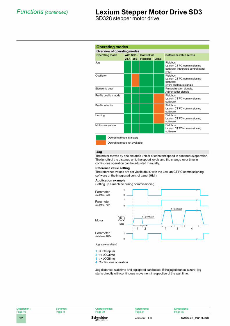
Operating modesOverview of operating modesOperating mode with SD3.. Control via Reference value set via
28 A 28B Fieldbus LocalJog Fieldbus,
Lexium CT PC commissioning software, integrated control panel (HMI)
Oscillator Fieldbus, Lexium CT PC commissioning software, ±0 V analogue signals
Electronic gear Pulse/direction signals, A/B encoder signals
Profile position mode Fieldbus, Lexium CT PC commissioning software
Profile velocity Fieldbus, Lexium CT PC commissioning software
Homing Fieldbus, Lexium CT PC commissioning software
Motion sequence Fieldbus, Lexium CT PC commissioning software
Operating mode available
Operating mode not available
JogThe motor moves by one distance unit or at constant speed in continuous operation. The length of the distance unit, the speed levels and the change-over time in continuous operation can be adjusted manually.Reference value settingThe reference values are set via fieldbus, with the Lexium CT PC commissioning software or the integrated control panel (HMI).Application exampleSetting up a machine during commissioning
Stop
1
0
1
0
1
0
M
startMan, Bit0
startMan, Bit2
stateMan, Bit14
n_slowMan
n_fastMan
Jog, slow and fast
JOGstepusrt < JOGtimet > JOGtimeContinuous operation
Jog distance, wait time and jog speed can be set. If the jog distance is zero, jog starts directly with continuous movement irrespective of the wait time.
1 2 3 4
Parameter
Parameter
Motor
Parameter 2 3 4
Description :Page 6
Schemes:Page 8
Characteristics:Page 30
References:Page 34
Dimensions:Page 35
62036-EN_Ver1.0.indd version: .0 23
Functions (continued) Lexium Stepper Motor Drive SD3 SD328 stepper motor drive
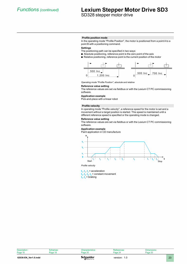
Profile position modeIn the operating mode "Profile Position", the motor is positioned from a point A to a point B with a positioning command.SettingsThe positioning path can be specified in two ways:
Absolute positioning, reference point is the zero point of the axisRelative positioning, reference point is the current position of the motor
1.200 Inc
500 Inc500 Inc
0700 Inc
0
Operating mode "Profile Position", absolute and relative
Reference value settingThe reference values are set via fieldbus or with the Lexium CT PC commissioning software.Application examplePick-and-place with a linear robot
bb
Profile velocityIn operating mode "Profile velocity", a reference speed for the motor is set and a movement without a target position is started. This speed is maintained until a different reference speed is specified or the operating mode is changed.Reference value settingThe reference values are set via fieldbus or with the Lexium CT PC commissioning software.Application examplePaint application in CD manufacture
v
t Start Stop
t1 t2 t3 t4 t5 t6 t7
0v1
v2
v3
t8 t9
Profile velocity
t1, t3, t5 = accelerationt2, t4, t6, t8 = constant movementt7, t9 = braking
Description :Page 6
Schemes:Page 8
Characteristics:Page 30
References:Page 34
Dimensions:Page 35
62036-EN_Ver1.0.inddversion: .024
Functions (continued) Lexium Stepper Motor Drive SD3 SD328 stepper motor drive
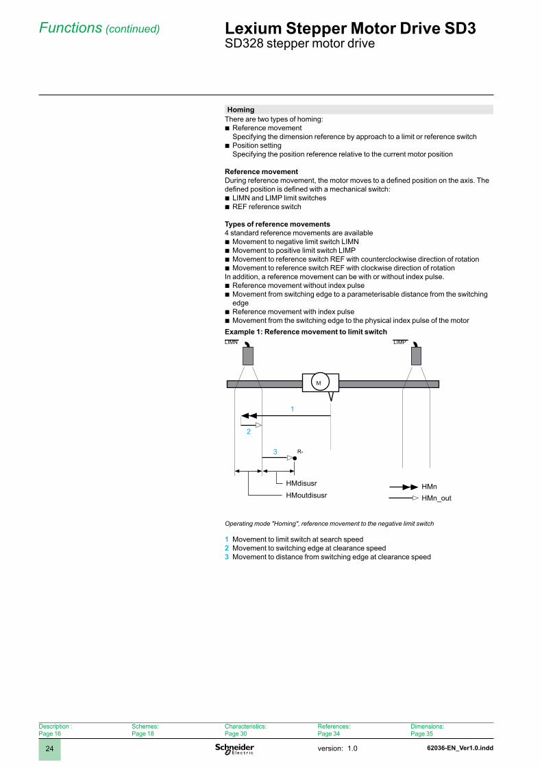
HomingThere are two types of homing:
Reference movement Specifying the dimension reference by approach to a limit or reference switchPosition setting Specifying the position reference relative to the current motor position
Reference movementDuring reference movement, the motor moves to a defined position on the axis. The defined position is defined with a mechanical switch:
LIMN and LIMP limit switchesREF reference switch
Types of reference movements4 standard reference movements are available
Movement to negative limit switch LIMNMovement to positive limit switch LIMPMovement to reference switch REF with counterclockwise direction of rotationMovement to reference switch REF with clockwise direction of rotation
In addition, a reference movement can be with or without index pulse.Reference movement without index pulseMovement from switching edge to a parameterisable distance from the switching edgeReference movement with index pulseMovement from the switching edge to the physical index pulse of the motor
Example 1: Reference movement to limit switch
M
R-
LIMN LIMP
1
2
3
Operating mode "Homing", reference movement to the negative limit switch
Movement to limit switch at search speedMovement to switching edge at clearance speedMovement to distance from switching edge at clearance speed
b
b
bb
bbbb
bb
bb
1 2 3
HMdisusrHMoutdisusr
HMnHMn_out
Description :Page 6
Schemes:Page 8
Characteristics:Page 30
References:Page 34
Dimensions:Page 35
62036-EN_Ver1.0.indd version: .0 25
Functions (continued) Lexium Stepper Motor Drive SD3 SD328 Stepper Motor Drive
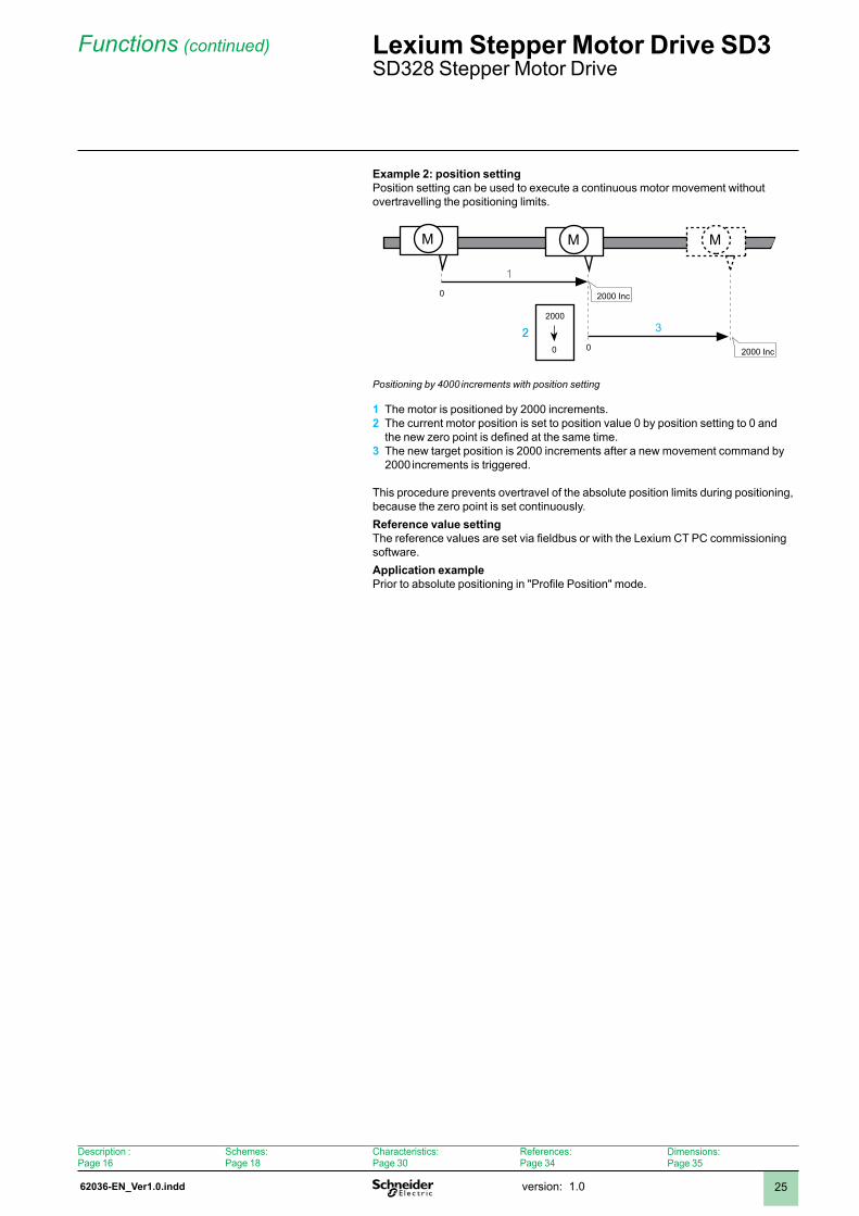
Example 2: position settingPosition setting can be used to execute a continuous motor movement without overtravelling the positioning limits.
M MM
0
00
2000 Inc
2000
2000 Inc
22
1
3
Positioning by 4000 increments with position setting
The motor is positioned by 2000 increments.The current motor position is set to position value 0 by position setting to 0 and the new zero point is defined at the same time.The new target position is 2000 increments after a new movement command by 2000 increments is triggered.
This procedure prevents overtravel of the absolute position limits during positioning, because the zero point is set continuously.Reference value settingThe reference values are set via fieldbus or with the Lexium CT PC commissioning software.Application examplePrior to absolute positioning in "Profile Position" mode.
1 2
3
Description :Page 6
Schemes:Page 8
Characteristics:Page 30
References:Page 34
Dimensions:Page 35
62036-EN_Ver1.0.inddversion: .026
Functions (continued) Lexium Stepper Motor Drive SD3 SD328 stepper motor drive
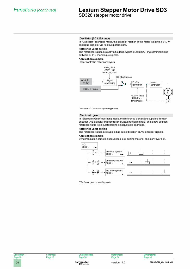
Oscillator (SD3 28A only)In "Oscillator" operating mode, the speed of rotation of the motor is set via a ±10-V analogue signal or via fieldbus parameters.Reference value settingThe reference values are set via fieldbus, with the Lexium CT PC commissioning software or ±0-V analogue signals.Application exampleRoller control in roller conveyors.
M3~
(±10V)
E
Overview of "Oscillator" operating mode
Electronic gearIn "Electronic Gear" operating mode, the reference signals are supplied from an encoder (A/B signals) or a controller (pulse/direction signals) and a new position reference value is calculated using an adjustable gear ratio.Reference value settingThe reference values are supplied as pulse/direction or A/B encoder signals.Application exampleSynchronisation of motion sequences, e.g. cutting material on a conveyor belt.
11
32
31
ZN
=
ZN
=
ZN
=
"Electronic gear" operating mode
Signal processing Profile
generatorMotorcontroller
st drive system: 200 Inc
2nd drive system:300 Inc
3rd drive system:600 Inc
NC: 200 Inc
ANA_IN
OSCL_n_target
ANA_offsetANA_win
ANA_n_scale
RAMPn_maxRAMPacc
RAMPdecel
OSCLreference
Description :Page 6
Schemes:Page 8
Characteristics:Page 30
References:Page 34
Dimensions:Page 35
62036-EN_Ver1.0.indd version: .0 27
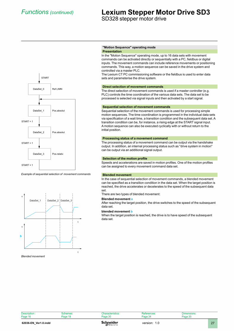
"Motion Sequence" operating modePresentation
In the "Motion Sequence" operating mode, up to 16 data sets with movement commands can be activated directly or sequentially with a PC, fieldbus or digital inputs. The movement commands can include reference movements or positioning commands. This way, a motion sequence can be saved in the drive system and controlled via a master PLC.The Lexium CT PC commissioning software or the fieldbus is used to enter data sets and parameterise the drive system.
Direct selection of movement commandsThe direct selection of movement commands is used if a master controller (e.g. PLC) controls the time coordination of the various data sets. The data set to be processed is selected via signal inputs and then activated by a start signal.
Sequential selection of movement commandsSequential selection of the movement commands is used for processing simple motion sequences. The time coordination is programmed in the individual data sets via specification of a wait time, a transition condition and the subsequent data set. A transition condition can be, for instance, a rising edge at the START signal input. A motion sequence can also be executed cyclically with or without return to the initial position.
Processing status of a movement commandThe processing status of a movement command can be output via the handshake output. In addition, an internal processing status such as "drive system in motion" can be output via an additional signal output.
Selection of the motion profileSpeeds and accelerations are saved in motion profiles. One of the motion profiles can be assigned to every movement command data set.
Blended movementIn the case of sequential selection of movement commands, a blended movement can be specified as a transition condition in the data set. When the target position is reached, the drive accelerates or decelerates to the speed of the subsequent data set.There are two types of blended movement:Blended movement aAfter reaching the target position, the drive switches to the speed of the subsequent data set.blended movement bWhen the target position is reached, the drive is to have speed of the subsequent data set.
Functions (continued) Lexium Stepper Motor Drive SD3 SD328 stepper motor drive
DataSet_1
DataSet_2
DataSet_3
DataSet_0 Ref.LIMN
Pos.absolut
Pos.absolut
Pos.relativ
START = 1
START = 1
START = 1
START
Example of sequential selection of movement commands
t
v
v
t
DataSet_1 DataSet_2 DataSet_3
Blended movement
b
Description :Page 6
Schemes:Page 8
Characteristics:Page 30
References:Page 34
Dimensions:Page 35
62036-EN_Ver1.0.inddversion: .028
Functions (continued) Lexium Stepper Motor Drive SD3 SD328 stepper motor drive
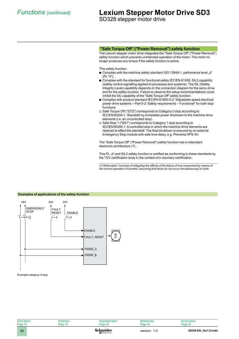
"Safe Torque Off" ("Power Removal") safety functionThe Lexium stepper motor drive integrates the "Safe Torque Off" ("Power Removal") safety function which prevents unintended operation of the motor. The motor no longer produces any torque if the safety function is active.
This safety function:Complies with the machine safety standard ISO 3849-, perfomance level „d“ (PL "d").Complies with the standard for functional safety IEC/EN 61508, SIL2 capability (safety control-signalling applied to processes and systems). The SIL (Safety Integrity Level) capability depends on the connection diagram for the servo drive and for the safety function. Failure to observe the setup recommendations could inhibit the SIL capability of the "Safe Torque Off" safety function.Complies with product standard IEC/EN 6800-5-2 "Adjustable speed electrical power drive systems – Part 5-2: Safety requirements – Functional" for both stop functions:Safe Torque Off ("STO") corresponds to Category 0 stop according to IEC/EN 60204-1. Standstill by immediate power shutdown to the machine drive elements (i.e. an uncontrolled stop).Safe Stop ("SS") corresponds to Category stop according to IEC/EN 60204-. A controlled stop in which the machine drive elements are retained to effect the standstill. The final shutdown is ensured by an external Emergency Stop module with safe time delay, e.g. Preventa XPS-AV.
The "Safe Torque Off" ("Power Removal") safety function has a redundant electronic architecture (1),.
This PL „d“ and SIL2 safety function is certified as conforming to these standards by the TÜV certification body in the context of a voluntary certification.
b
b
b
v
v
(1) Redundant: Consists of mitigating the effects of the failure of one component by means of the correct operation of another, assuming that faults do not occur simultaneously on both.
Examples of applications of the safety function
24V24V24V
M3~
ENABLE
FAULT_RESET
ENABLEFAULTRESET
PWRR_A
PWRR_B
Example category 0 stop
EMERGENCY STOP
Description :Page 6
Schemes:Page 8
Characteristics:Page 30
References:Page 34
Dimensions:Page 35
62036-EN_Ver1.0.indd version: .0 29
Functions (continued) Lexium Stepper Motor Drive SD3 SD328 stepper motor drive
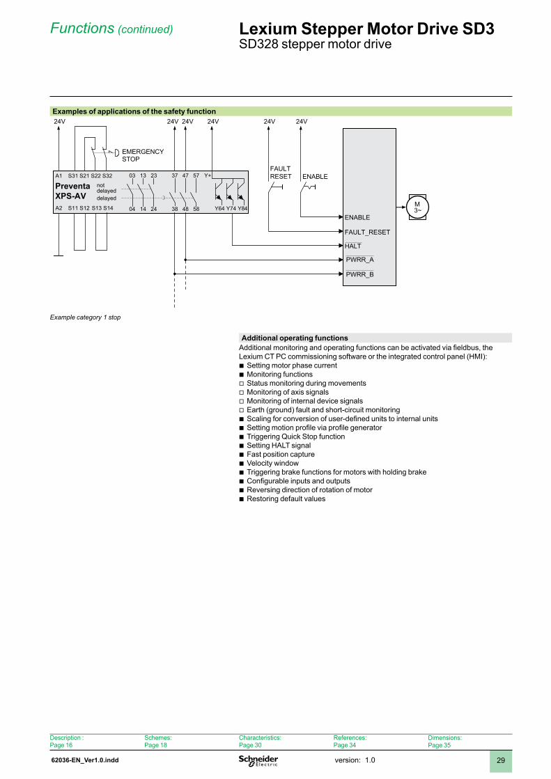
Additional operating functionsAdditional monitoring and operating functions can be activated via fieldbus, the Lexium CT PC commissioning software or the integrated control panel (HMI):
Setting motor phase currentMonitoring functionsStatus monitoring during movementsMonitoring of axis signalsMonitoring of internal device signalsEarth (ground) fault and short-circuit monitoringScaling for conversion of user-defined units to internal unitsSetting motion profile via profile generatorTriggering Quick Stop functionSetting HALT signalFast position capture Velocity windowTriggering brake functions for motors with holding brakeConfigurable inputs and outputsReversing direction of rotation of motorRestoring default values
bbvvvvbbbbbbbbbb
Examples of applications of the safety function24V24V24V
S11 S12 Y64 Y74 Y8438 48 58
37 47 57S31 S21 S22 S32
A2
A1
24V 24V
S13 S14
03 13 23
04 14 24
Y+
24V
M3~
PreventaXPS-AV
ENABLE
FAULT_RESET
HALT
ENABLEFAULTRESET
PWRR_B
PWRR_A
Example category 1 stop
notdelayeddelayed
EMERGENCY STOP
Description :Page 6
Schemes:Page 8
Characteristics:Page 30
References:Page 34
Dimensions:Page 35
62037-EN_Ver1.0.inddversion: .030
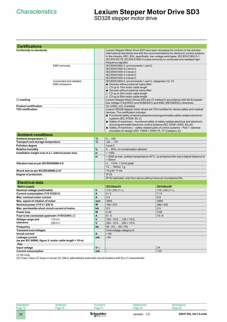
CertificationsConformity to standards Lexium Stepper Motor Drive SD3 have been developed to conform to the strictest
international standards and with the recommendations for electronic control systems in the industry (IEC, EN), specifically: low-voltage switchgear, IEC/EN 61800-5-1, IEC/EN 5078, IEC/EN 6800-3 (noise immunity to conducted and radiated high-frequency signals)
EMC immunity IEC/EN 6800-3, environments and 2;IEC/EN 6000-4-2 level 3;IEC/EN 6000-4-3 level 3;IEC/EN 6000-4-4 level 4;IEC/EN 6000-4-5 level 3;
Conducted and radiated EMC emissions
IEC/EN 6800-3, environments and 2, categories C2, C3Devices without external mains filter:C3 up to 10m motor cable lengthDevices without external mains filter: C2 up to 20m motor cable lengthC3 up to 50m motor cable length
bvbvv
e marking Lexium Stepper Motor Drives SD3 are e marked in accordance with the European low voltage (73/23/EEC and 93/68/EEC) and EMC (89/336/EEC) directives.
Product certification UL (USA), cUL (Canada)TÜV certification Lexium SD328 stepper motor drives are TÜV-certified for device safety and medical
devices. The certification includes:Functional safety of electrical/electronic/programmable safety-related electronic systems (IEC 6508; SIL 2)Safety of machinery – functional safety of safety-related electrical and electronic and programmable electronic control systems (IEC 62061:2005; SILcl2)Safety of machinery – safety-related parts of control systems – Part : General principles for design (ISO 13849-1:2006; PL "d" (Category 3))
b
b
b
Ambient conditionsAmbient temperature (1) °C 0 ... +50Transport and storage temperature °C -25 ... +70 Pollution degree Level 2Relative humidity % 5 ... 85%, no condensation allowedInstallation height over m.s.l. without power loss m < 000
m < 2000 at max. ambient temperature 40°C, no protective film and a lateral distance of > 50mm
Vibration test as per IEC/EN 60068-2-6 3 ... 13 Hz: 1.5 mm peak13 ... 150 Hz: 1 g
Shock test as per IEC/EN 60068-2-27 5 g for msDegree of protection IP 20
IP 40 restricted: only from above without removal of protective film.
Electrical dataMains supply SD328pU25 SD328pU28
Nominal voltage (switchable) V 5 / 230 (∿) 5 / 230 (∿)Current consumption (115 V/230 V) A 4 / 3 7 / 5Max. nominal motor current A 2.5 6.8Max. speed of rotation of motor rpm 3000 3000Nominal power (115 V / 230 V) W 80 / 270 280 / 420Max. permissible short circuit current of mains kA 0.5 0.5Power loss W y 26 y 65Fuse to be connected upstream (115V/230V) (2) A 6 / 6 0 / 6Voltage range and tolerance
5 Vz V 00 - 5 % ... 20 + 0 %230 Vz V 200 - 5 % ... 240 + 0 %
Frequency Hz 50 - 5% ... 60 + 5%Transient overvoltages Overvoltage category IIIInrush current A < 60Leakage current (as per IEC 60990, figure 3; motor cable length < 10 m)
mA <30
FanInput voltage Vc - 24Current consumption mA - 30(1) No icing(2) Fuses: class CC fuses or as per UL 248-4, alternatively automatic circuit breakers with B or C characteristic
Characteristics Lexium Stepper Motor Drive SD3 SD328 stepper motor drive
Description :Page 6
Schemes:Page 8
Functions:Page 2
References:Page 34
Dimensions:Page 35
62037-EN_Ver1.0.indd version: .0 3
Characteristics (continued) Lexium Stepper Motor Drive SD3 SD328 stepper motor drive
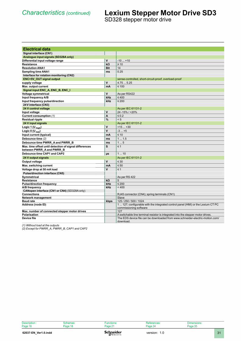
Electrical dataSignal interface (CN1)Analogue input signals (SD328A only)
Differential input voltage range V -0 ... +0Resistance kΩ u 0 Resolution ANA1 Bit 4Sampling time ANA1 ms 0.25Interface for rotation monitoring (CN2)ENC+5V_OUT signal output sense-controlled, short-circuit-proof, overload-proof
supply voltage V 4.75 ... 5.25Max. output current mA y 00Signal input ENC_A, ENC_B, ENC_I
Voltage symmetrical V As per RS422Input frequency A/B kHz y 400Input frequency pulse/direction kHz y 20024 V interface (CN3)24 V control voltage As per IEC 63-2
Input voltage V 24 -5% / +20%Current consumption (1) A y 0.2Residual ripple % < 524 V input signals As per IEC 63-2
Logic 1 (U high) V +5 ... +30Logic 0 (U low) V -3 ... +5 Input current (typical) mA y 0Debounce time (2) ms ... .5 Debounce time PWRR_A and PWRR_B ms ... 5 Max. time offset until detection of signal differences between PWRR_A and PWRR_B
S y
Debounce time CAP1 and CAP2 µs ... 024 V output signals As per IEC 63-2
Output voltage V y 30Max. switching current mA y 50 Voltage drop at 50 mA load V y Pulse/direction interface (CN5)
Symmetrical As per RS 422Resistance kΩ 5Pulse/direction frequency kHz y 200A/B frequency kHz < 400CANopen interface (CN1 or CN4) (SD328A only)
Connections RJ45 connector (CN4); spring terminals (CN)Network management SlaveBaud rate kbps 25 / 250 / 500 / 024Address (node ID) 1 ... 127; configurable with the integrated control panel (HMI) or the Lexium CT PC
commissioning softwareMax. number of connected stepper motor drives 27Polarisation A switchable line terminal resistor is integrated into the stepper motor drives.Device file The EDS device file can be downloaded from www.schneider-electric-motion.com/
download.(1) Without load at the outputs(2) Except for PWRR_A, PWRR_B, CAP1 and CAP2
Description :Page 6
Schemes:Page 8
Functions:Page 2
References:Page 34
Dimensions:Page 35
62037-EN_Ver1.0.inddversion: .032
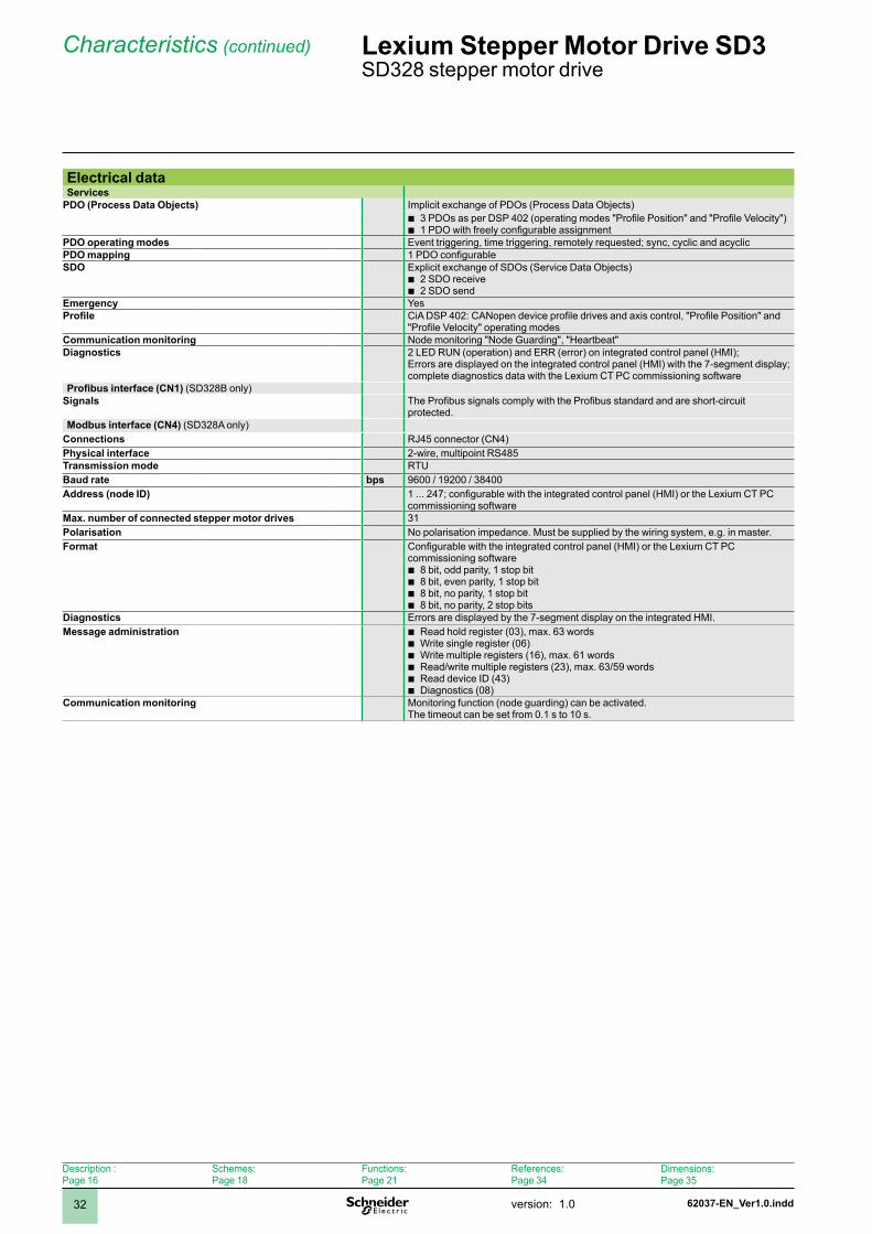
Electrical dataServices
PDO (Process Data Objects) Implicit exchange of PDOs (Process Data Objects) 3 PDOs as per DSP 402 (operating modes "Profile Position" and "Profile Velocity")1 PDO with freely configurable assignment
bb
PDO operating modes Event triggering, time triggering, remotely requested; sync, cyclic and acyclicPDO mapping 1 PDO configurableSDO Explicit exchange of SDOs (Service Data Objects)
2 SDO receive2 SDO send
bb
Emergency YesProfile CiA DSP 402: CANopen device profile drives and axis control, "Profile Position" and
"Profile Velocity" operating modesCommunication monitoring Node monitoring "Node Guarding", "Heartbeat"Diagnostics 2 LED RUN (operation) and ERR (error) on integrated control panel (HMI);
Errors are displayed on the integrated control panel (HMI) with the 7-segment display; complete diagnostics data with the Lexium CT PC commissioning software
Profibus interface (CN1) (SD328B only)Signals The Profibus signals comply with the Profibus standard and are short-circuit
protected.Modbus interface (CN4) (SD328A only)
Connections RJ45 connector (CN4)Physical interface 2-wire, multipoint RS485Transmission mode RTUBaud rate bps 9600 / 9200 / 38400Address (node ID) 1 ... 247; configurable with the integrated control panel (HMI) or the Lexium CT PC
commissioning softwareMax. number of connected stepper motor drives 3Polarisation No polarisation impedance. Must be supplied by the wiring system, e.g. in master.Format Configurable with the integrated control panel (HMI) or the Lexium CT PC
commissioning software8 bit, odd parity, 1 stop bit8 bit, even parity, 1 stop bit8 bit, no parity, 1 stop bit8 bit, no parity, 2 stop bits
bbbb
Diagnostics Errors are displayed by the 7-segment display on the integrated HMI.Message administration Read hold register (03), max. 63 words
Write single register (06)Write multiple registers (6), max. 6 wordsRead/write multiple registers (23), max. 63/59 wordsRead device ID (43)Diagnostics (08)
bbbbbb
Communication monitoring Monitoring function (node guarding) can be activated. The timeout can be set from 0.1 s to 10 s.
Characteristics (continued) Lexium Stepper Motor Drive SD3 SD328 stepper motor drive
Description :Page 6
Schemes:Page 8
Functions:Page 2
References:Page 34
Dimensions:Page 35
62037-EN_Ver1.0.indd version: .0 33
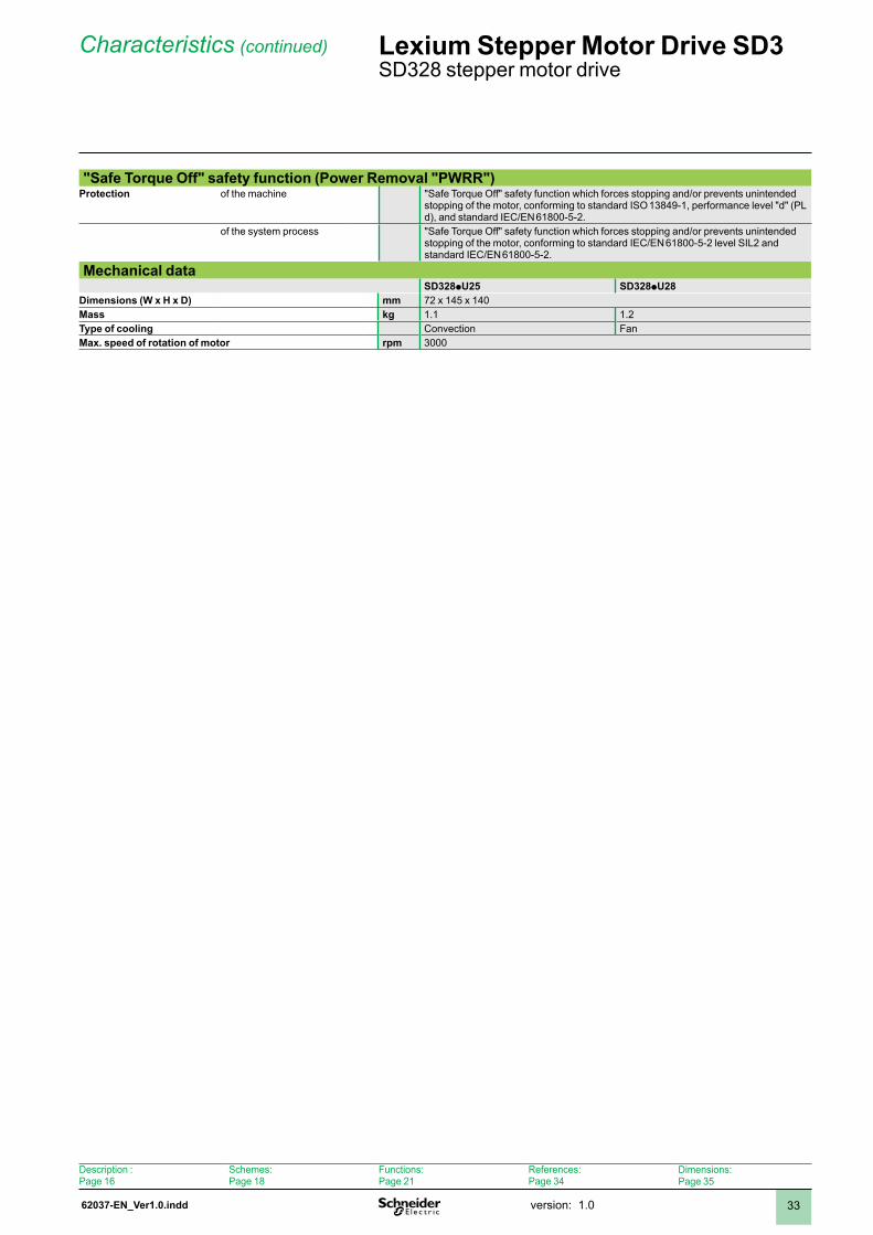
"Safe Torque Off" safety function (Power Removal "PWRR")Protection of the machine "Safe Torque Off" safety function which forces stopping and/or prevents unintended
stopping of the motor, conforming to standard ISO 13849-1, performance level "d" (PL d), and standard IEC/EN 6800-5-2.
of the system process "Safe Torque Off" safety function which forces stopping and/or prevents unintended stopping of the motor, conforming to standard IEC/EN 6800-5-2 level SIL2 and standard IEC/EN 6800-5-2.
Mechanical dataSD328pU25 SD328pU28
Dimensions (W x H x D) mm 72 x 45 x 40Mass kg . .2Type of cooling Convection FanMax. speed of rotation of motor rpm 3000
Characteristics (continued) Lexium Stepper Motor Drive SD3 SD328 stepper motor drive
Description :Page 6
Schemes:Page 8
Functions:Page 2
References:Page 34
Dimensions:Page 35

62038-EN_Ver1.0.inddversion: .034
References Lexium Stepper Motor Drive SD3 SD328 stepper motor drive
Order codeExample: SD3 28 A U25 S2
Product designationSD3 = stepper motor drive 3-phase
SD3 28 A U25 S2
Product type28 = standard stepper motor drive for fieldbus
SD3 28 A U25 S2
InterfacesA = CANopen fieldbus, Modbus fieldbus and analogue inputB = Profibus fieldbus
SD3 28 A U25 S2
Max. motor phase currentU25 = 2.5 AU68 = 6.8 A
SD3 28 A U25 S2
Power amplifier supply voltageS2 = ∿, 5 Vz / 230 Vz (switching)
SD3 28 A U25 S2
SD328 stepper motor drive
Description :Page 6
Schemes:Page 8
Functions:Page 2
Characteristics:Page 30
Dimensions:Page 35
62038-EN_Ver1.0.indd version: .0 35
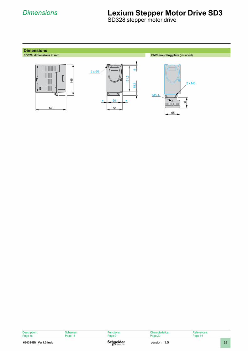
Dimensions Lexium Stepper Motor Drive SD3 SD328 stepper motor drive
DimensionsSD328, dimensions in mm EMC mounting plate (included)
2 x Ø5
140
60
121,
5
518
,5145
= =
72
50
M5t
2 x M5
68
Description :Page 6
Schemes:Page 8
Functions:Page 2
Characteristics:Page 30
References:Page 34
62039-EN_Ver1.0.inddversion: .036
Mounting and installation recommendations
Lexium Stepper Motor Drive SD3 SD32p stepper motor drive
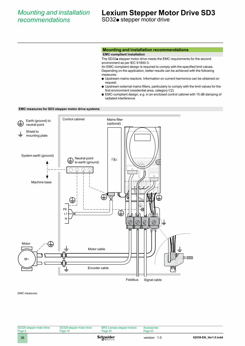
Mounting and installation recommendationsEMC-compliant installation
The SD32p stepper motor drive meets the EMC requirements for the second environment as per IEC 6800-3.An EMC-compliant design is required to comply with the specified limit values. Depending on the application, better results can be achieved with the following measures:
Upstream mains reactors. Information on current harmonics can be obtained on request.Upstream external mains filters, particularly to comply with the limit values for the first environment (residential area, category C2)EMC-compliant design, e.g. in an enclosed control cabinet with 15 dB damping of radiated interference
b
b
b
EMC measures for SD3 stepper motor drive systems
L1PE
N
M~
EMC measures
Earth (ground) toneutral point
Shield tomounting plate
Control cabinet Mains filter(optional)
System earth (ground)
Machine base
Neutral pointto earth (ground)
Motor
Motor cable
Encoder cable
Signal cable
SD326 stepper motor drivePage 4
SD328 stepper motor drivePage 6
BRS 3-phase stepper motors:Page 40
Accessories:Page 52
Fieldbus

62039-EN_Ver1.0.indd version: .0 37
Mounting and installation recommendations (continued)
Lexium Stepper Motor Drive SD3 SD32p stepper motor drive
Operation in IT mainsAn IT mains is characterised by a neutral conductor that is isolated or earthed (grounded) through a high impedance. If permanent isolation monitoring is used, it must be suitable for non-linear loads (e.g. type XM200 from Merlin Gerin). If an error is signalled in spite of correct wiring, the earth (ground) connection of the Y capacitors of products with an integrated mains filter can be disconnected (deactivate Y capacitors).
In the case of all other mains systems except for IT mains the earth connection via the Y capacitors remain effective.
If the earth (ground) connection of the Y capacitors is disconnected, the specifications for radiation of electromagnetic interference are no longer complied with! Always ensure compliance with national regulations and standards by means of separate measures.
PE
1
2
Operation in IT mains
Isolation monitoring errorY capacitors of the internal filter effective (standard)Y capacitors of the internal filter deactivated (IT mains)
1 2
SD326 stepper motor drivePage 4
SD328 stepper motor drivePage 6
BRS 3-phase stepper motors:Page 40
Accessories:Page 52
62039-EN_Ver1.0.inddversion: .038
Mounting and installation recommendations (continued)
Lexium Stepper Motor Drive SD3 SD32p stepper motor drive
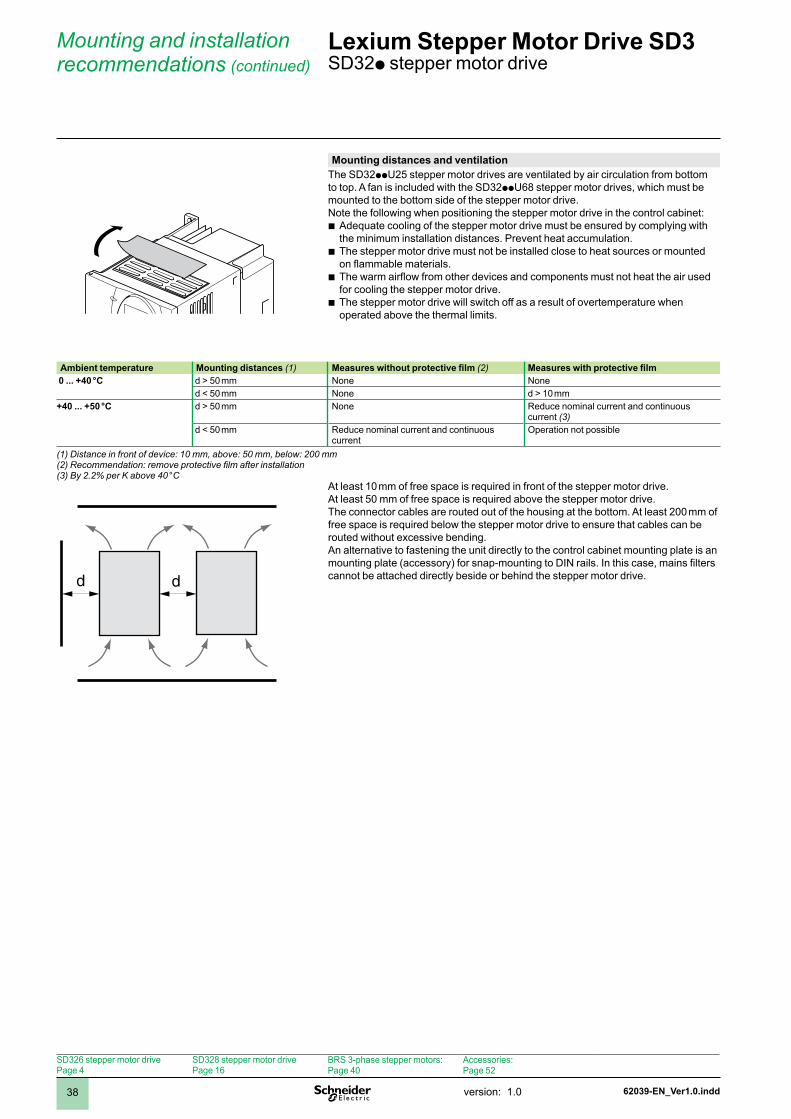
Mounting distances and ventilationThe SD32ppU25 stepper motor drives are ventilated by air circulation from bottom to top. A fan is included with the SD32ppU68 stepper motor drives, which must be mounted to the bottom side of the stepper motor drive.Note the following when positioning the stepper motor drive in the control cabinet:
Adequate cooling of the stepper motor drive must be ensured by complying with the minimum installation distances. Prevent heat accumulation.The stepper motor drive must not be installed close to heat sources or mounted on flammable materials.The warm airflow from other devices and components must not heat the air used for cooling the stepper motor drive.The stepper motor drive will switch off as a result of overtemperature when operated above the thermal limits.
b
b
b
b
Ambient temperature Mounting distances (1) Measures without protective film (2) Measures with protective film 0 ... +40 °C d > 50 mm None None
d < 50 mm None d > 0 mm+40 ... +50 °C d > 50 mm None Reduce nominal current and continuous
current (3) d < 50 mm Reduce nominal current and continuous
currentOperation not possible
(1) Distance in front of device: 10 mm, above: 50 mm, below: 200 mm(2) Recommendation: remove protective film after installation(3) By 2.2% per K above 40 °C
dd
At least 0 mm of free space is required in front of the stepper motor drive.At least 50 mm of free space is required above the stepper motor drive.The connector cables are routed out of the housing at the bottom. At least 200 mm of free space is required below the stepper motor drive to ensure that cables can be routed without excessive bending.An alternative to fastening the unit directly to the control cabinet mounting plate is an mounting plate (accessory) for snap-mounting to DIN rails. In this case, mains filters cannot be attached directly beside or behind the stepper motor drive.
SD326 stepper motor drivePage 4
SD328 stepper motor drivePage 6
BRS 3-phase stepper motors:Page 40
Accessories:Page 52
62039-EN_Ver1.0.indd version: .0 39
Mounting and installation recommendations (continued)
Lexium Stepper Motor Drive SD3 SD32p Stepper Motor Drive
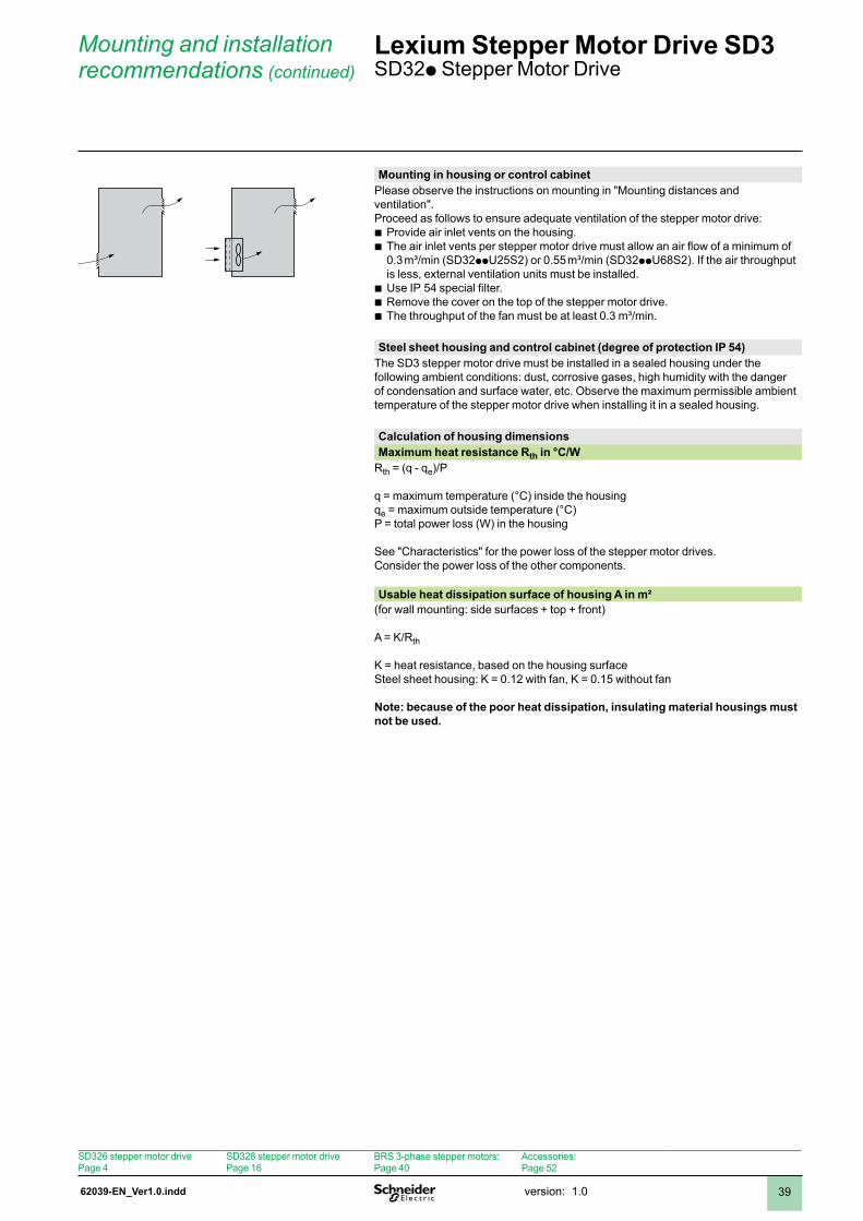
Mounting in housing or control cabinetPlease observe the instructions on mounting in "Mounting distances and ventilation".Proceed as follows to ensure adequate ventilation of the stepper motor drive:
Provide air inlet vents on the housing.The air inlet vents per stepper motor drive must allow an air flow of a minimum of 0.3 m³/min (SD32ppU25S2) or 0.55 m³/min (SD32ppU68S2). If the air throughput is less, external ventilation units must be installed.Use IP 54 special filter.Remove the cover on the top of the stepper motor drive.The throughput of the fan must be at least 0.3 m³/min.
bb
bbb
Steel sheet housing and control cabinet (degree of protection IP 54)The SD3 stepper motor drive must be installed in a sealed housing under the following ambient conditions: dust, corrosive gases, high humidity with the danger of condensation and surface water, etc. Observe the maximum permissible ambient temperature of the stepper motor drive when installing it in a sealed housing.
Calculation of housing dimensionsMaximum heat resistance Rth in °C/W
Rth = (q - qe)/P
q = maximum temperature (°C) inside the housingqe = maximum outside temperature (°C)P = total power loss (W) in the housing
See "Characteristics" for the power loss of the stepper motor drives.Consider the power loss of the other components.
Usable heat dissipation surface of housing A in m²(for wall mounting: side surfaces + top + front)
A = K/Rth
K = heat resistance, based on the housing surfaceSteel sheet housing: K = 0.2 with fan, K = 0.5 without fan
Note: because of the poor heat dissipation, insulating material housings must not be used.
SD326 stepper motor drivePage 4
SD328 stepper motor drivePage 6
BRS 3-phase stepper motors:Page 40
Accessories:Page 52
62040-EN_Ver1.0.inddversion: .040
Presentation Lexium Stepper Motor Drive SD3 BRS3 3-phase stepper motors
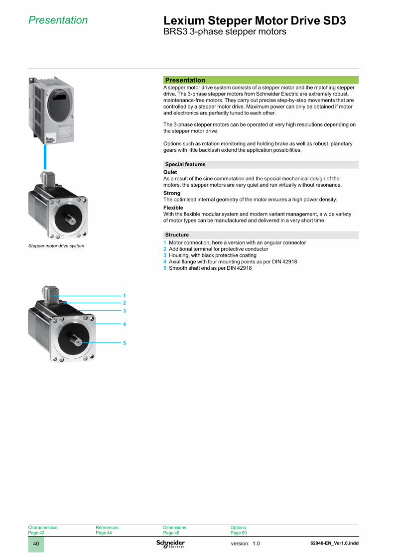
PresentationA stepper motor drive system consists of a stepper motor and the matching stepper drive. The 3-phase stepper motors from Schneider Electric are extremely robust, maintenance-free motors. They carry out precise step-by-step movements that are controlled by a stepper motor drive. Maximum power can only be obtained if motor and electronics are perfectly tuned to each other.
The 3-phase stepper motors can be operated at very high resolutions depending on the stepper motor drive.
Options such as rotation monitoring and holding brake as well as robust, planetary gears with little backlash extend the application possibilities.
Special featuresQuietAs a result of the sine commutation and the special mechanical design of the motors, the stepper motors are very quiet and run virtually without resonance.StrongThe optimised internal geometry of the motor ensures a high power density; FlexibleWith the flexible modular system and modern variant management, a wide variety of motor types can be manufactured and delivered in a very short time.
StructureMotor connection, here a version with an angular connectorAdditional terminal for protective conductorHousing, with black protective coatingAxial flange with four mounting points as per DIN 42918Smooth shaft end as per DIN 4298
1 2 3 4 5
Stepper motor drive system
123
4
5
Characteristics:Page 42
References:Page 44
Dimensions:Page 46
Options:Page 50
62040-EN_Ver1.0.indd version: .0 4
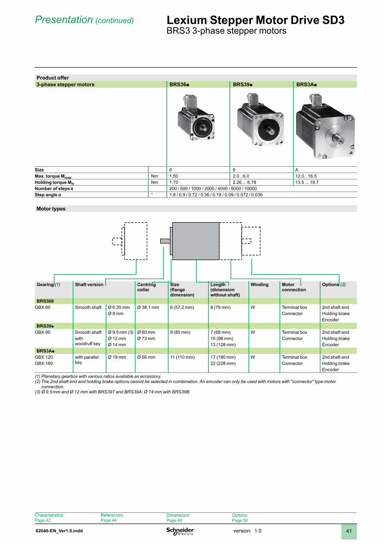
Product offer3-phase stepper motors BRS36p BRS39p BRS3Ap
Size 6 9 AMax. torque Mmax Nm .50 2.0...6.0 2.0...6.5Holding torque MH Nm .70 2.26 ... 6.78 3.5 ... 9.7Number of steps z 200 / 500 / 000 / 2000 / 4000 / 5000 / 0000Step angle α ° .8 / 0.9 / 0.72 / 0.36 / 0.8 / 0.09 / 0.072 / 0.036
Motor types
Gearing (1) Shaft version Centring collar
Size(flange dimension)
Length(dimension without shaft)
Winding Motor connection
Options (2)
BRS368GBX 60 Smooth shaft Ø 6.35 mm Ø 38. mm 6 (57.2 mm) 8 (79 mm) W Terminal box 2nd shaft end
Ø 8 mm Connector Holding brakeEncoder
BRS39pGBX 80 Smooth shaft Ø 9.5 mm (3) Ø 60 mm 9 (85 mm) 7 (68 mm) W Terminal box 2nd shaft end
with woodruff key
Ø 2 mm Ø 73 mm 0 (98 mm) Connector Holding brakeØ 4 mm 3 (28 mm) Encoder
BRS3ApGBX 20 with parallel
keyØ 9 mm Ø 56 mm (0 mm) 7 (80 mm) W Terminal box 2nd shaft end
GBX 60 22 (228 mm) Connector Holding brakeEncoder
(1) Planetary gearbox with various ratios available as accessory.(2) The 2nd shaft end and holding brake options cannot be selected in combination. An encoder can only be used with motors with "connector" type motor
connection.(3) Ø 9.5 mm and Ø 12 mm with BRS397 and BRS39A; Ø 14 mm with BRS39B
Presentation (continued) Lexium Stepper Motor Drive SD3 BRS3 3-phase stepper motors
Characteristics:Page 42
References:Page 44
Dimensions:Page 46
Options:Page 50
62041-EN_Ver1.0.inddversion: .042
Characteristics Lexium Stepper Motor Drive SD3 BRS3 3-phase stepper motors
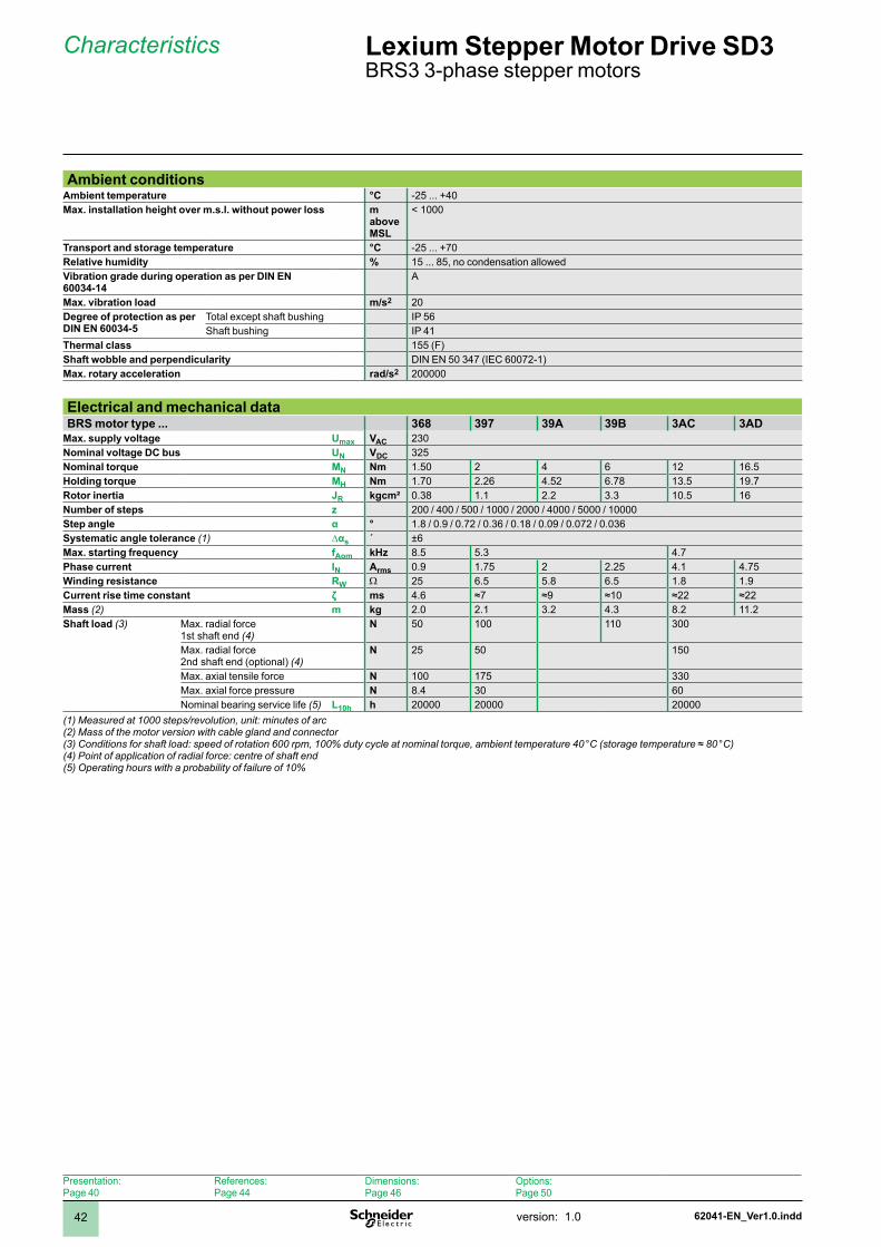
Ambient conditions Ambient temperature °C -25 ... +40Max. installation height over m.s.l. without power loss m
above MSL
< 000
Transport and storage temperature °C -25 ... +70Relative humidity % 5 ... 85, no condensation allowedVibration grade during operation as per DIN EN 60034-14
A
Max. vibration load m/s2 20Degree of protection as per DIN EN 60034-5
Total except shaft bushing IP 56Shaft bushing IP 4
Thermal class 55 (F)Shaft wobble and perpendicularity DIN EN 50 347 (IEC 60072-)Max. rotary acceleration rad/s2 200000
Electrical and mechanical dataBRS motor type ... 368 397 39A 39B 3AC 3AD
Max. supply voltage Umax VAC 230Nominal voltage DC bus UN VDC 325Nominal torque MN Nm .50 2 4 6 2 6.5Holding torque MH Nm .70 2.26 4.52 6.78 3.5 9.7Rotor inertia JR kgcm² 0.38 . 2.2 3.3 0.5 6Number of steps z 200 / 400 / 500 / 000 / 2000 / 4000 / 5000 / 0000Step angle α ° .8 / 0.9 / 0.72 / 0.36 / 0.8 / 0.09 / 0.072 / 0.036Systematic angle tolerance (1) ∆αs ´ ±6Max. starting frequency fAom kHz 8.5 5.3 4.7Phase current IN Arms 0.9 .75 2 2.25 4. 4.75Winding resistance RW W 25 6.5 5.8 6.5 .8 .9Current rise time constant ζ ms 4.6 ≈7 ≈9 ≈10 ≈22 ≈22Mass (2) m kg 2.0 2. 3.2 4.3 8.2 .2Shaft load (3) Max. radial force
st shaft end (4) N 50 00 0 300
Max. radial force 2nd shaft end (optional) (4)
N 25 50 50
Max. axial tensile force N 00 75 330Max. axial force pressure N 8.4 30 60 Nominal bearing service life (5) L10h h 20000 20000 20000
(1) Measured at 1000 steps/revolution, unit: minutes of arc(2) Mass of the motor version with cable gland and connector(3) Conditions for shaft load: speed of rotation 600 rpm, 100% duty cycle at nominal torque, ambient temperature 40 °C (storage temperature ≈ 80 °C)(4) Point of application of radial force: centre of shaft end(5) Operating hours with a probability of failure of 10%
Presentation:Page 40
References:Page 44
Dimensions:Page 46
Options:Page 50
62041-EN_Ver1.0.indd version: .0 43
Characteristics (continued) Lexium Stepper Motor Drive SD3 BRS3 3-phase stepper motors
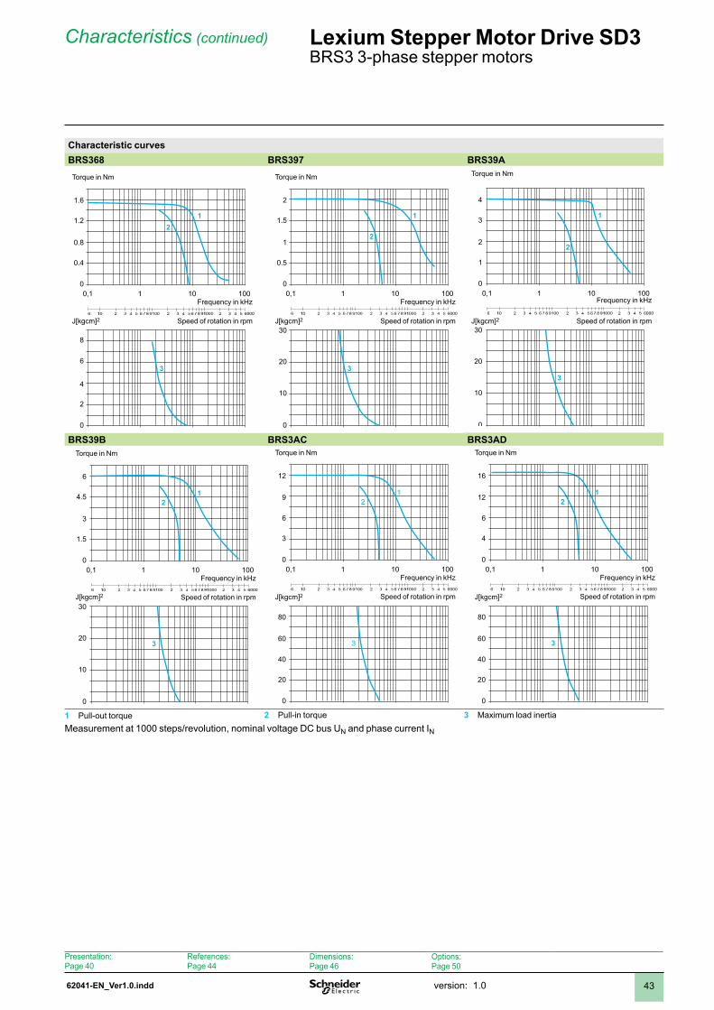
Characteristic curvesBRS368 BRS397 BRS39A
0,1 1 10010
21
3
0
0.4
0.8
1.2
1.6
0
4
2
6
8
Torque in Nm
Frequency in kHz
Speed of rotation in rpmJ[kgcm]2
0,1 1 10010
2
1
3
0
0.5
1
1.5
2
0
10
20
30
Torque in Nm
Frequency in kHz
Speed of rotation in rpmJ[kgcm]2
0,1 1 10010
2
1
3
0
1
2
3
4
0
10
20
30
Torque in Nm
Frequency in kHz
Speed of rotation in rpmJ[kgcm]2
BRS39B BRS3AC BRS3AD
0,1 1 10010
21
3
0
1.5
3
4.5
6
0
10
20
30
Torque in Nm
Frequency in kHz
Speed of rotation in rpmJ[kgcm]2
0,1 1 10010
21
3
0
3
6
9
12
0
20
40
60
80
Torque in Nm
Frequency in kHz
Speed of rotation in rpmJ[kgcm]2
0,1 1 10010
21
3
0
4
6
12
16
0
20
40
60
80
Torque in Nm
Frequency in kHz
Speed of rotation in rpmJ[kgcm]2
1 Pull-out torque 2 Pull-in torque 3 Maximum load inertiaMeasurement at 1000 steps/revolution, nominal voltage DC bus UN and phase current IN
Presentation:Page 40
References:Page 44
Dimensions:Page 46
Options:Page 50
62042-EN_Ver1.0.inddversion: .044
References Lexium Stepper Motor Drive SD3 BRS3 3-phase stepper motors
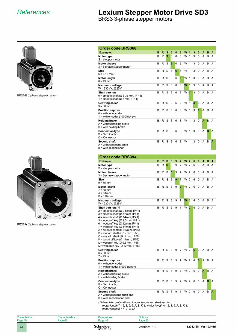
Order code BRS368Example: B R S 3 6 8 W 1 3 0 A B A
Motor typeS = stepper motor
B R S 3 6 8 W 3 0 A B A
Motor phases 3 = 3-phase stepper motor
B R S 3 6 8 W 3 0 A B A
Size6 = 57.2 mm
B R S 3 6 8 W 3 0 A B A
Motor length8 = 79 mm
B R S 3 6 8 W 3 0 A B A
Maximum voltageW = 230 Vz (325 Vc)
B R S 3 6 8 W 3 0 A B A
Shaft version0 = smooth shaft (Ø 6.35 mm, IP 4) = smooth shaft (Ø 8 mm, IP 4)
B R S 3 6 8 W 1 3 0 A B A
Centring collar3 = 38 mm
B R S 3 6 8 W 3 0 A B A
Position capture0 = without encoder = with encoder (000 inc/rev)
B R S 3 6 8 W 3 0 A B A
Holding brakeA = without holding brakeB = with holding brake
B R S 3 6 8 W 3 0 A B A
Connection type B = Terminal boxC = Connector
B R S 3 6 8 W 3 0 A B A
Second shaftA = without second shaftB = with second shaft
B R S 3 6 8 W 3 0 A B A
Order code BRS39pExample: B R S 3 9 7 W 2 6 0 A B A
Motor typeS = stepper motor
B R S 3 9 7 W 2 6 0 A B A
Motor phases 3 = 3-phase stepper motor
B R S 3 9 7 W 2 6 0 A B A
Size9 = 85 mm
B R S 3 9 7 W 2 6 0 A B A
Motor length7 = 68 mmA = 98 mmB = 28 mm
B R S 3 9 7 W 2 6 0 A B A
Maximum voltageW = 230 Vz (325 Vc)
B R S 3 9 7 W 2 6 0 A B A
Shaft version (1)2 = smooth shaft (Ø 9.5 mm, IP4)3 = smooth shaft (Ø 2 mm, IP4)4 = smooth shaft (Ø 4 mm, IP4)5 = woodruff key (Ø 9.5 mm, IP41)6 = woodruff key (Ø 12 mm, IP41)7 = woodruff key (Ø 14 mm, IP41)A = smooth shaft (Ø 9.5 mm, IP56)B = smooth shaft (Ø 2 mm, IP56)C = smooth shaft (Ø 4 mm, IP56)K = woodruff key (Ø 14 mm, IP56)L = woodruff key (Ø 9.5 mm, IP56)M = woodruff key (Ø 12 mm, IP56)
B R S 3 9 7 W 2 6 0 A B A
Centring collar6 = 60 mm7 = 73 mm
B R S 3 9 7 W 2 6 0 A B A
Position capture0 = without encoder = with encoder (000 Inc/rev)
B R S 3 9 7 W 2 6 0 A B A
Holding brakeA = without holding brakeF = with holding brake
B R S 3 9 7 W 2 6 0 A B A
Connection type B = Terminal boxC = Connector
B R S 3 9 7 W 2 6 0 A B A
Second shaftA = without second shaft endB = with second shaft end
B R S 3 9 7 W 2 6 0 A B A
(1) Possible combinations of motor length and shaft version:: motor length 7 = 2, 3, 5, 6, A, B, K, L; motor length A = 2, 3, 5, A, B, K, L; motor length B = 4, 7, C, M
BRS368 3-phase stepper motor
BRS39p 3-phase stepper motor
Presentation:Page 40
Characteristics:Page 42
Dimensions:Page 46
Options:Page 50

62042-EN_Ver1.0.indd version: .0 45
References (continued) Lexium Stepper Motor Drive SD3 BRS3 3-phase stepper motors
Order code BRS3ApExample: B R S 3 A C W 8 5 0 A B A
Motor typeS = stepper motor
B R S 3 A C W 8 5 0 A B A
Motor phases 3 = 3-phase stepper motor
B R S 3 A C W 8 5 0 A B A
SizeA = 0 mm
B R S 3 A C W 8 5 0 A B A
Motor lengthC = 80 mmD = 230 mm
B R S 3 A C W 8 5 0 A B A
Maximum voltageW = 230 Vz (325 Vc)
B R S 3 A C W 8 5 0 A B A
Shaft version8 = parallel key (Ø 19 mm, IP41)
B R S 3 A C W 8 5 0 A B A
Centring collar5 = 56 mm
B R S 3 A C W 8 5 0 A B A
Position capture0 = without encoder = with encoder (000 Inc/rev)
B R S 3 A C W 8 5 0 A B A
Holding brakeA = without holding brakeF = with holding brake
B R S 3 A C W 8 5 0 A B A
Connection type B = Terminal boxC = Connector
B R S 3 A C W 8 5 0 A B A
Second shaftA = without second shaft endB = with second shaft end
B R S 3 A C W 8 5 0 A B A
BRS3Ap 3-phase stepper motor
Presentation:Page 40
Characteristics:Page 42
Dimensions:Page 46
Options:Page 50
62043-EN_Ver1.0.inddversion: .046
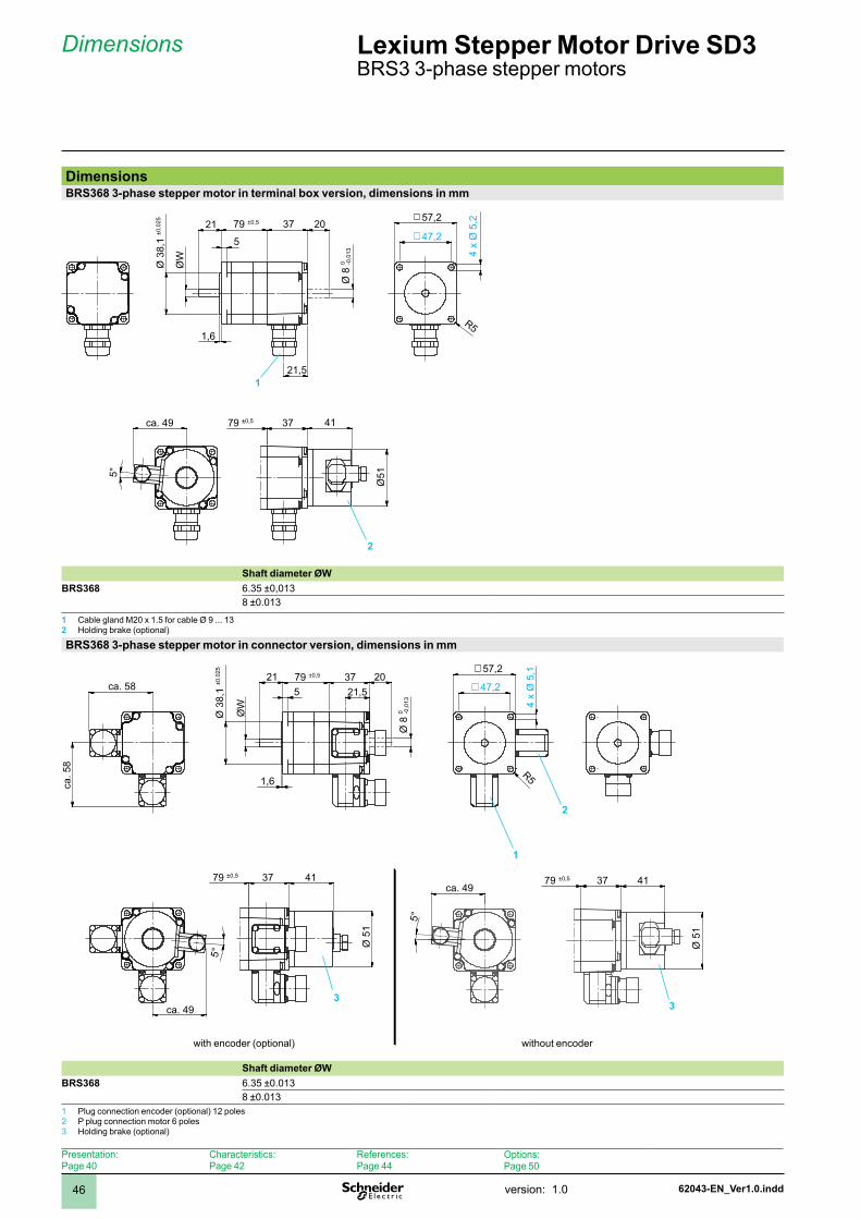
Dimensions Lexium Stepper Motor Drive SD3 BRS3 3-phase stepper motors
DimensionsBRS368 3-phase stepper motor in terminal box version, dimensions in mm
5°
5
21 37 20
Ø51
4137
R5
21,5
79 ±0,5ca. 49
Ø 3
8,1
±0,0
25
1,6
ØW
79 ±0,5
47,2
57,2
4 x
Ø 5
,2
Ø 8
-0,0
130
Shaft diameter ØWBRS368 6.35 ±0,03
8 ±0.03
1 Cable gland M20 x 1.5 for cable Ø 9 ... 132 Holding brake (optional)
BRS368 3-phase stepper motor in connector version, dimensions in mm
R5
2021 375
5°
41
Ø 5
1
37
Ø 5
1
5°
4137
Ø 8
-0,0
130
21,5 47,2
57,2
4 x
Ø 5
,1
Ø 3
8,1
±0,0
25
79 ±0,5
1,6
79 ±0,5 79 ±0,5
ca. 58
ca. 49
ca. 49
ca. 5
8
ØW
Shaft diameter ØWBRS368 6.35 ±0.03
8 ±0.03 Plug connection encoder (optional) 2 poles2 P plug connection motor 6 poles3 Holding brake (optional)
1
2
with encoder (optional) without encoder
33
2
1
Presentation:Page 40
Characteristics:Page 42
References:Page 44
Options:Page 50
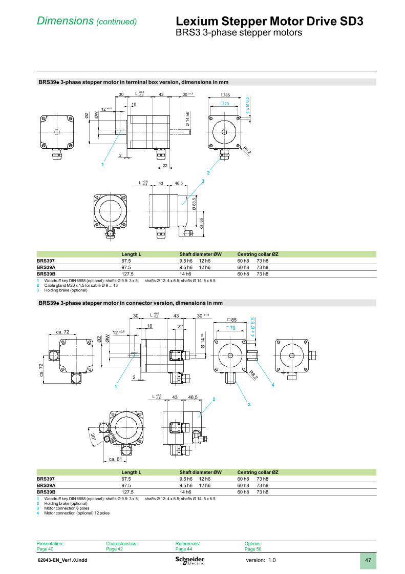
62043-EN_Ver1.0.indd version: .0 47
Dimensions (continued) Lexium Stepper Motor Drive SD3 BRS3 3-phase stepper motors
BRS39p 3-phase stepper motor in terminal box version, dimensions in mm
22
43
70
8530
10
2
43
Ø 1
4 h6ØZ
ØW
12 ±0,5
46,5
4 x
Ø 6
,5
R8,2
30 ±1,5L +0,6-0,8
Ø 8
3,5
ca. 6
6
L +0,6-0,8
Length L Shaft diameter ØW Centring collar ØZBRS397 67.5 9.5 h6 2 h6 60 h8 73 h8BRS39A 97.5 9.5 h6 2 h6 60 h8 73 h8BRS39B 27.5 4 h6 60 h8 73 h81 Woodruff key DIN 6888 (optional): shafts Ø 9.5: 3 x 5; shafts Ø 12: 4 x 6.5; shafts Ø 14: 5 x 6.52 Cable gland M20 x 1,5 for cable Ø 9 ... 133 Holding brake (optional)
BRS39p 3-phase stepper motor in connector version, dimensions in mm
30°
22 70
85
43
43
10
2
30
Ø 1
4 h6
ØZ
ØW
ca. 72
ca. 7
2
12 ±0,5
4 x
Ø 6
,5
R8,2
30 ±1,5
46,5
ca. 61
L +0,6-0,8
L +0,6-0,8
Length L Shaft diameter ØW Centring collar ØZBRS397 67.5 9,5 h6 2 h6 60 h8 73 h8BRS39A 97.5 9.5 h6 2 h6 60 h8 73 h8BRS39B 27.5 4 h6 60 h8 73 h81 Woodruff key DIN 6888 (optional): shafts Ø 9.5: 3 x 5; shafts Ø 12: 4 x 6.5; shafts Ø 14: 5 x 6.52 Holding brake (optional)3 Motor connection 6 poles4 Motor connection (optional) 2 poles
1
23
23
41
Presentation:Page 40
Characteristics:Page 42
References:Page 44
Options:Page 50
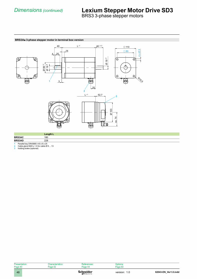
62043-EN_Ver1.0.inddversion: .048
Dimensions (continued) Lexium Stepper Motor Drive SD3 BRS3 3-phase stepper motors
BRS3Ap 3-phase stepper motor in terminal box version
25
4 25
3
14
40 L ±1Ø
19
j6
Ø 5
6 h7 Ø
19
h7
89
110
4 x
Ø 9
L ±1
Ø 1
03
40 ±1,5
52,7
R10,5
ca. 7
4
Length LBRS3AC 80BRS3AD 2281 Parallel key DIN 6885: A 6 x 6 x 252 Cable gland M20 x 1.5 for cable Ø 9 ... 133 holding brake (optional)
1
2
3
Presentation:Page 40
Characteristics:Page 42
References:Page 44
Options:Page 50
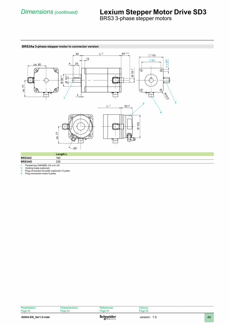
62043-EN_Ver1.0.indd version: .0 49
Dimensions (continued) Lexium Stepper Motor Drive SD3 BRS3 3-phase stepper motors
BRS3Ap 3-phase stepper motor in connector version
4 25
3
14
40 L ±1
Ø 1
9 j6
Ø 5
6 h7 Ø
19
h7
89
110
4 x
Ø9
L ±1
Ø 1
03
30°
ca. 85
ca. 7
7
52,7
R10,5
40 ±1,5
ca. 7
7
Length LBRS3AC 80BRS3AD 2281 Parallel key DIN 6885: A 6 x 6 x 252 Holding brake (optional)3 Plug connection encoder (optional) 2 poles4 Plug connection motor 6 poles
1
4
32
Presentation:Page 40
Characteristics:Page 42
References:Page 44
Options:Page 50
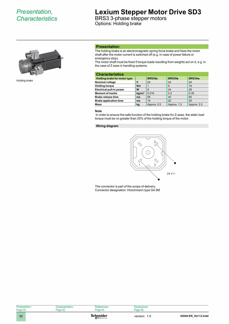
62044-EN_Ver1.0.inddversion: .050
PresentationThe holding brake is an electromagnetic spring force brake and fixes the motor shaft after the motor current is switched off (e.g. in case of power failure or emergency stop). The motor shaft must be fixed if torque loads resulting from weights act on it, e.g. in the case of Z axes in handling systems.
CharacteristicsHolding brake for motor type BRS36p BRS39p BRS3Ap
Nominal voltage V 24 24 24Holding torque Nm 6 6Electrical pull-in power W 8 24 28Moment of inertia kgcm² 0.06 0.2 0.35Brake release time ms 58 40 60Brake application time ms 4 20 30Mass kg Approx. 0.5 Approx. .5 Approx. 2.0
Note In order to ensure the safe function of the holding brake for Z-axes, the static load torque must be no greater than 25% of the holding torque of the motor.
Wiring diagram
1 3
2
24 Vc
The connector is part of the scope of delivery.Connector designation: Hirschmann type G4 5M
Presentation, Characteristics
Lexium Stepper Motor Drive SD3 BRS3 3-phase stepper motorsOptions: Holding brake
Holding brake
Presentation:Page 40
Characteristics:Page 42
References:Page 44
Dimensions:Page 46
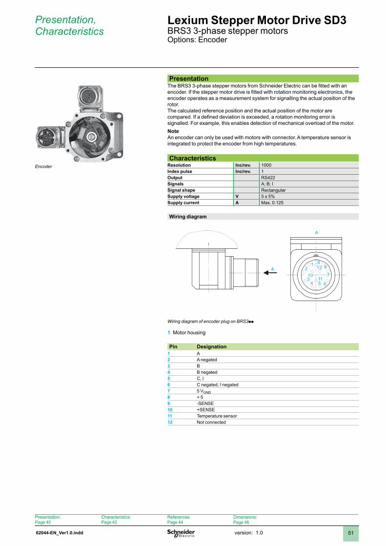
62044-EN_Ver1.0.indd version: .0 5
Presentation, Characteristics
Lexium Stepper Motor Drive SD3 BRS3 3-phase stepper motorsOptions: Encoder
PresentationThe BRS3 3-phase stepper motors from Schneider Electric can be fitted with an encoder. If the stepper motor drive is fitted with rotation monitoring electronics, the encoder operates as a measurement system for signalling the actual position of the rotor. The calculated reference position and the actual position of the motor are compared. If a defined deviation is exceeded, a rotation monitoring error is signalled. For example, this enables detection of mechanical overload of the motor. Note An encoder can only be used with motors with connector. A temperature sensor is integrated to protect the encoder from high temperatures.
CharacteristicsResolution Inc/rev. 000Index pulse Inc/rev. Output RS422Signals A; B; ISignal shape RectangularSupply voltage V 5 ± 5%Supply current A Max. 0.25
Wiring diagram
1
A1 9
8
7
6
12
1154
3
210
A
Wiring diagram of encoder plug on BRS3pp
Motor housing1
Pin Designation1 A2 A negated3 B4 B negated5 C, I6 C negated, I negated7 5 VGND8 + 59 -SENSE10 +SENSE11 Temperature sensor12 Not connected
Encoder
Presentation:Page 40
Characteristics:Page 42
References:Page 44
Dimensions:Page 46
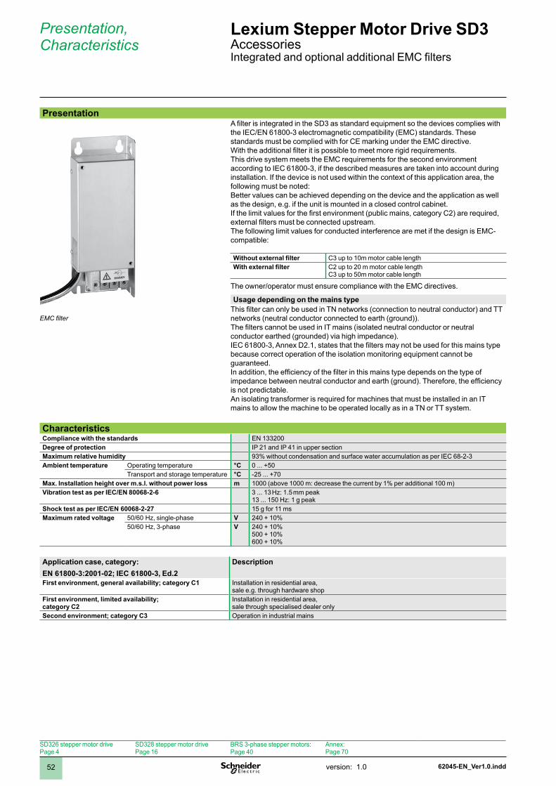
62045-EN_Ver1.0.inddversion: .052
PresentationA filter is integrated in the SD3 as standard equipment so the devices complies with the IEC/EN 61800-3 electromagnetic compatibility (EMC) standards. These standards must be complied with for CE marking under the EMC directive.With the additional filter it is possible to meet more rigid requirements.This drive system meets the EMC requirements for the second environment according to IEC 61800-3, if the described measures are taken into account during installation. If the device is not used within the context of this application area, the following must be noted:Better values can be achieved depending on the device and the application as well as the design, e.g. if the unit is mounted in a closed control cabinet.If the limit values for the first environment (public mains, category C2) are required, external filters must be connected upstream.The following limit values for conducted interference are met if the design is EMC-compatible:
Without external filter C3 up to 10m motor cable lengthWith external filter C2 up to 20 m motor cable length
C3 up to 50m motor cable length
The owner/operator must ensure compliance with the EMC directives.
Usage depending on the mains typeThis filter can only be used in TN networks (connection to neutral conductor) and TT networks (neutral conductor connected to earth (ground)).The filters cannot be used in IT mains (isolated neutral conductor or neutral conductor earthed (grounded) via high impedance).IEC 61800-3, Annex D2.1, states that the filters may not be used for this mains type because correct operation of the isolation monitoring equipment cannot be guaranteed.In addition, the efficiency of the filter in this mains type depends on the type of impedance between neutral conductor and earth (ground). Therefore, the efficiency is not predictable.An isolating transformer is required for machines that must be installed in an IT mains to allow the machine to be operated locally as in a TN or TT system.
Presentation, Characteristics
Lexium Stepper Motor Drive SD3 AccessoriesIntegrated and optional additional EMC filters
CharacteristicsCompliance with the standards EN 33200Degree of protection IP 2 and IP 4 in upper sectionMaximum relative humidity 93% without condensation and surface water accumulation as per IEC 68-2-3Ambient temperature Operating temperature °C 0 ... +50
Transport and storage temperature °C -25 ... +70Max. Installation height over m.s.l. without power loss m 1000 (above 1000 m: decrease the current by 1% per additional 100 m)Vibration test as per IEC/EN 80068-2-6 3 ... 13 Hz: 1.5 mm peak
13 ... 150 Hz: 1 g peakShock test as per IEC/EN 60068-2-27 5 g for msMaximum rated voltage 50/60 Hz, single-phase V 240 + 0%
50/60 Hz, 3-phase V 240 + 0%500 + 0%600 + 0%
Application case, category:EN 61800-3:2001-02; IEC 61800-3, Ed.2
Description
First environment, general availability; category C1 Installation in residential area, sale e.g. through hardware shop
First environment, limited availability; category C2
Installation in residential area, sale through specialised dealer only
Second environment; category C3 Operation in industrial mains
EMC filter
SD326 stepper motor drivePage 4
SD328 stepper motor drivePage 6
BRS 3-phase stepper motors:Page 40
Annex:Page 70
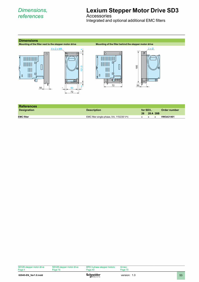
62045-EN_Ver1.0.indd version: .0 53
Dimensions, references
Lexium Stepper Motor Drive SD3 AccessoriesIntegrated and optional additional EMC filters
DimensionsMounting of the filter next to the stepper motor drive Mounting of the filter behind the stepper motor drive
121,
5=
=
60= =
72
4 x 2 x M4
505072
185
2 x Ø
ReferencesDesignation Description for SD3.. Order number
26 28 A 28BEMC filter EMC filter single-phase, 9 A, 115/230 Vz x x x VW3A31401
SD326 stepper motor drivePage 4
SD328 stepper motor drivePage 6
BRS 3-phase stepper motors:Page 40
Annex:Page 70
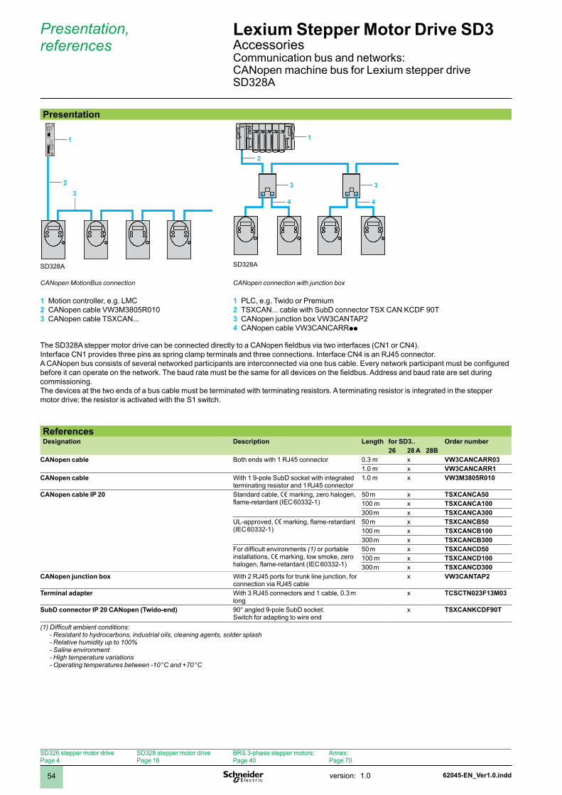
62045-EN_Ver1.0.inddversion: .054
Presentation, references
Lexium Stepper Motor Drive SD3 AccessoriesCommunication bus and networks:CANopen machine bus for Lexium stepper drive SD328A
Presentation
SD328A SD328A
CANopen MotionBus connection
Motion controller, e.g. LMCCANopen cable VW3M3805R010CANopen cable TSXCAN...
1 2 3
CANopen connection with junction box
PLC, e.g. Twido or PremiumTSXCAN... cable with SubD connector TSX CAN KCDF 90TCANopen junction box VW3CANTAP2CANopen cable VW3CANCARRpp
1 2 3 4
ReferencesDesignation Description Length for SD3.. Order number
26 28 A 28BCANopen cable Both ends with RJ45 connector 0.3 m x VW3CANCARR03
.0 m x VW3CANCARR1CANopen cable With 1 9-pole SubD socket with integrated
terminating resistor and RJ45 connector.0 m x VW3M3805R010
CANopen cable IP 20 Standard cable, e marking, zero halogen, flame-retardant (IEC 60332-1)
50 m x TSXCANCA5000 m x TSXCANCA100300 m x TSXCANCA300
UL-approved, e marking, flame-retardant (IEC 60332-)
50 m x TSXCANCB5000 m x TSXCANCB100300 m x TSXCANCB300
For difficult environments (1) or portable installations, e marking, low smoke, zero halogen, flame-retardant (IEC 60332-1)
50 m x TSXCANCD5000 m x TSXCANCD100300 m x TSXCANCD300
CANopen junction box With 2 RJ45 ports for trunk line junction, for connection via RJ45 cable
x VW3CANTAP2
Terminal adapter With 3 RJ45 connectors and 1 cable, 0.3 m long
x TCSCTN023F13M03
SubD connector IP 20 CANopen (Twido-end) 90° angled 9-pole SubD socket.Switch for adapting to wire end
x TSXCANKCDF90T
(1) Difficult ambient conditions: - Resistant to hydrocarbons, industrial oils, cleaning agents, solder splash - Relative humidity up to 100% - Saline environment - High temperature variations - Operating temperatures between -10 °C and +70 °C
The SD328A stepper motor drive can be connected directly to a CANopen fieldbus via two interfaces (CN1 or CN4). Interface CN provides three pins as spring clamp terminals and three connections. Interface CN4 is an RJ45 connector.A CANopen bus consists of several networked participants are interconnected via one bus cable. Every network participant must be configured before it can operate on the network. The baud rate must be the same for all devices on the fieldbus. Address and baud rate are set during commissioning.The devices at the two ends of a bus cable must be terminated with terminating resistors. A terminating resistor is integrated in the stepper motor drive; the resistor is activated with the S switch.
1
2
1
2
3
4
3
43
SD326 stepper motor drivePage 4
SD328 stepper motor drivePage 6
BRS 3-phase stepper motors:Page 40
Annex:Page 70
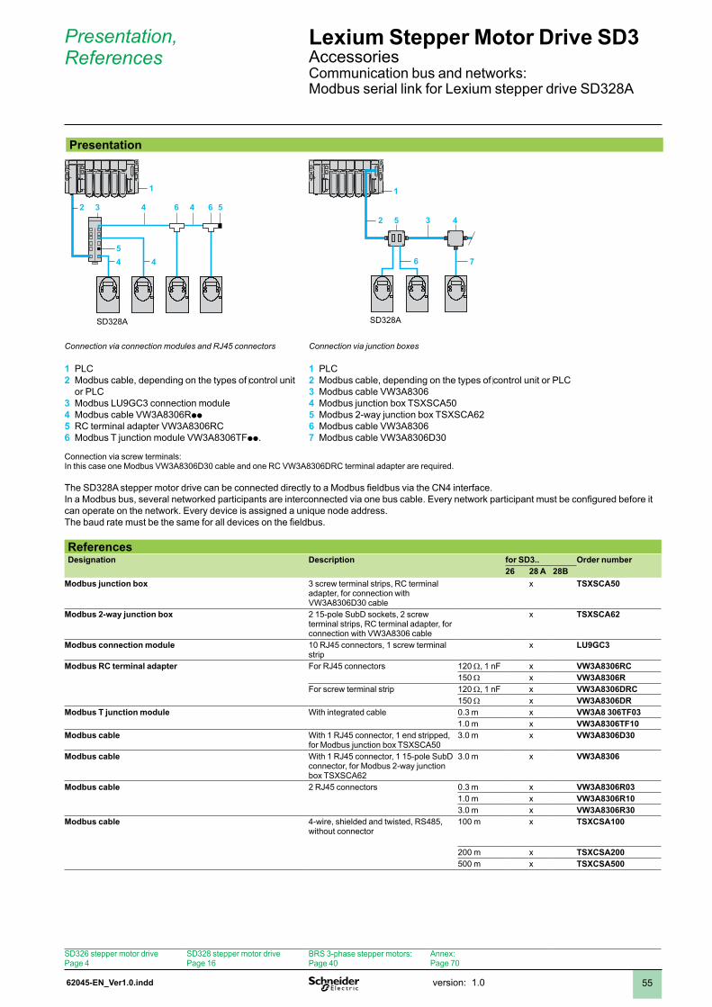
62045-EN_Ver1.0.indd version: .0 55
Presentation
SD328A
3
Presentation, References
Lexium Stepper Motor Drive SD3 AccessoriesCommunication bus and networks:Modbus serial link for Lexium stepper drive SD328A
SD328A
Connection via connection modules and RJ45 connectors
PLCModbus cable, depending on the types of control unit or PLCModbus LU9GC3 connection moduleModbus cable VW3A8306RppRC terminal adapter VW3A8306RCModbus T junction module VW3A8306TFpp.
1 2
3 4 5 6
Connection via junction boxes
PLCModbus cable, depending on the types of control unit or PLCModbus cable VW3A8306Modbus junction box TSXSCA50Modbus 2-way junction box TSXSCA62Modbus cable VW3A8306Modbus cable VW3A8306D30
1 2 3 4 5 6 7
Connection via screw terminals: In this case one Modbus VW3A8306D30 cable and one RC VW3A8306DRC terminal adapter are required.
The SD328A stepper motor drive can be connected directly to a Modbus fieldbus via the CN4 interface. In a Modbus bus, several networked participants are interconnected via one bus cable. Every network participant must be configured before it can operate on the network. Every device is assigned a unique node address.The baud rate must be the same for all devices on the fieldbus.
ReferencesDesignation Description for SD3.. Order number
26 28 A 28BModbus junction box 3 screw terminal strips, RC terminal
adapter, for connection with VW3A8306D30 cable
x TSXSCA50
Modbus 2-way junction box 2 15-pole SubD sockets, 2 screw terminal strips, RC terminal adapter, for connection with VW3A8306 cable
x TSXSCA62
Modbus connection module 0 RJ45 connectors, screw terminal strip
x LU9GC3
Modbus RC terminal adapter For RJ45 connectors 20 W, nF x VW3A8306RC50 W x VW3A8306R
For screw terminal strip 20 W, nF x VW3A8306DRC50 W x VW3A8306DR
Modbus T junction module With integrated cable 0.3 m x VW3A8 306TF03.0 m x VW3A8306TF10
Modbus cable With RJ45 connector, end stripped, for Modbus junction box TSXSCA50
3.0 m x VW3A8306D30
Modbus cable With 1 RJ45 connector, 1 15-pole SubD connector, for Modbus 2-way junction box TSXSCA62
3.0 m x VW3A8306
Modbus cable 2 RJ45 connectors 0.3 m x VW3A8306R03.0 m x VW3A8306R103.0 m x VW3A8306R30
Modbus cable 4-wire, shielded and twisted, RS485, without connector
00 m x TSXCSA100
200 m x TSXCSA200500 m x TSXCSA500
4 46 6 52
445
1
5 32 4
6 7
1
SD326 stepper motor drivePage 4
SD328 stepper motor drivePage 6
BRS 3-phase stepper motors:Page 40
Annex:Page 70
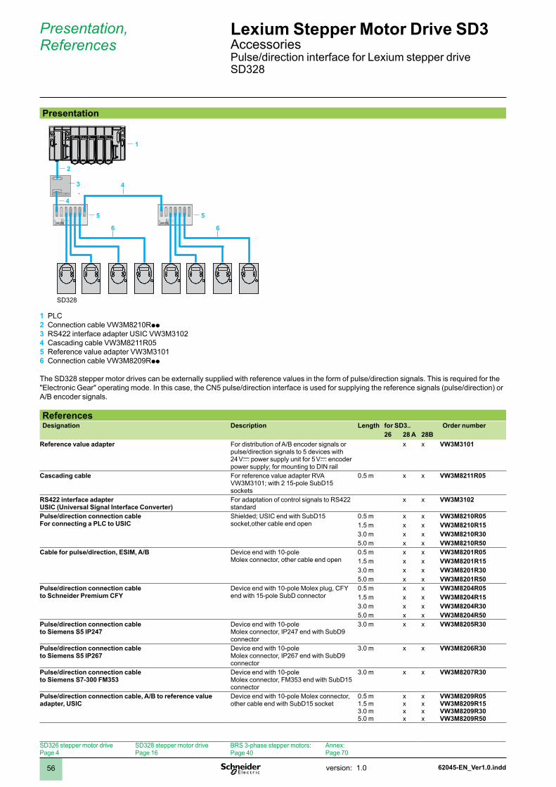
62045-EN_Ver1.0.inddversion: .056
Presentation, References
Lexium Stepper Motor Drive SD3 AccessoriesPulse/direction interface for Lexium stepper drive SD328
Presentation
OFFS1CN9
CN80VDC
ACTIVE (CN1...CN5 )
5VSE
41 32 5
1
8
9
15
1
8
9
15
1
8
9
15
1
8
9
15
1
8
9
15
1
8
9
15
8
1
15
9
24VDC
OFFS1CN9
CN80VDC
ACTIVE (CN1...CN5 )
5VSE
41 32 5
1
8
9
15
1
8
9
15
1
8
9
15
1
8
9
15
1
8
9
15
1
8
9
15
8
1
15
9
24VDC
8 1
15 9
8 1
15 9
SD328
PLC Connection cable VW3M8210RppRS422 interface adapter USIC VW3M302Cascading cable VW3M8211R05Reference value adapter VW3M30Connection cable VW3M8209Rpp
The SD328 stepper motor drives can be externally supplied with reference values in the form of pulse/direction signals. This is required for the "Electronic Gear" operating mode. In this case, the CN5 pulse/direction interface is used for supplying the reference signals (pulse/direction) or A/B encoder signals.
ReferencesDesignation Description Length for SD3.. Order number
26 28 A 28BReference value adapter For distribution of A/B encoder signals or
pulse/direction signals to 5 devices with 24 Vc power supply unit for 5 Vc encoder power supply; for mounting to DIN rail
x x VW3M3101
Cascading cable For reference value adapter RVA VW3M3101; with 2 15-pole SubD15 sockets
0.5 m x x VW3M8211R05
RS422 interface adapter USIC (Universal Signal Interface Converter)
For adaptation of control signals to RS422 standard
x x VW3M3102
Pulse/direction connection cable For connecting a PLC to USIC
Shielded; USIC end with SubD15 socket,other cable end open
0.5 m x x VW3M8210R05.5 m x x VW3M8210R153.0 m x x VW3M8210R305.0 m x x VW3M8210R50
Cable for pulse/direction, ESIM, A/B Device end with 0-poleMolex connector, other cable end open
0.5 m x x VW3M8201R05.5 m x x VW3M8201R153.0 m x x VW3M8201R305.0 m x x VW3M8201R50
Pulse/direction connection cable to Schneider Premium CFY
Device end with 0-pole Molex plug, CFY end with 15-pole SubD connector
0.5 m x x VW3M8204R05.5 m x x VW3M8204R153.0 m x x VW3M8204R305.0 m x x VW3M8204R50
Pulse/direction connection cable to Siemens S5 IP247
Device end with 0-poleMolex connector, IP247 end with SubD9 connector
3.0 m x x VW3M8205R30
Pulse/direction connection cable to Siemens S5 IP267
Device end with 0-pole Molex connector, IP267 end with SubD9 connector
3.0 m x x VW3M8206R30
Pulse/direction connection cable to Siemens S7-300 FM353
Device end with 0-pole Molex connector, FM353 end with SubD15 connector
3.0 m x x VW3M8207R30
Pulse/direction connection cable, A/B to reference value adapter, USIC
Device end with 0-pole Molex connector, other cable end with SubD15 socket
0.5 m.5 m3.0 m5.0 m
xxxx
xxxx
VW3M8209R05VW3M8209R15VW3M8209R30VW3M8209R50
1 2 3 4 5 6
3 4
4
2
1
5
6
5
6
SD326 stepper motor drivePage 4
SD328 stepper motor drivePage 6
BRS 3-phase stepper motors:Page 40
Annex:Page 70
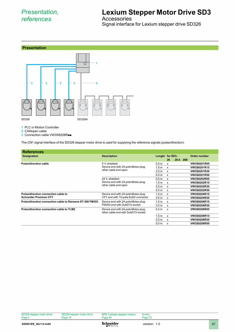
62045-EN_Ver1.0.indd version: .0 57
Presentation, references
Lexium Stepper Motor Drive SD3 AccessoriesSignal interface for Lexium stepper drive SD326
Presentation
SD326 SD328A
PLC or Motion ControllerCANopen cableConnection cable VW3S8208Rpp
The CN signal interface of the SD326 stepper motor drive is used for supplying the reference signals (pulse/direction).
1 2 3
ReferencesDesignation Description Length for SD3.. Order number
26 28 A 28BPulse/direction cable 5 V, shielded;
Device end with 24-pole Molex plug;other cable end open
0.5 m x VW3S8201R05.5 m x VW3S8201R153.0 m x VW3S8201R305.0 m x VW3S8201R50
24 V, shielded;Device end with 24-pole Molex plug;other cable end open
0.5 m x VW3S8202R05.5 m x VW3S8202R153.0 m x VW3S8202R305.0 m x VW3S8202R50
Pulse/direction connection cable toSchneider Premium CFY
Device end with 24-pole Molex plug;CFY end with 15-pole SubD connector
.5 m x VW3S8204R153.0 m x VW3S8204R30
Pulse/direction connection cable to Siemens S7-300 FM353 Device end with 24-pole Molex plug;FM353 end with SubD15 socket
.5 m x VW3S8206R153.0 m x VW3S8206R30
Pulse/direction connection cable to TLM2 Device end with 24-pole Molex plug;other cable end with SubD15 socket
0.5 m x VW3S8208R05
.5 m x VW3S8208R153.0 m x VW3S8208R305.0 m x VW3S8208R50
3 3 3 3 2
1
SD326 stepper motor drivePage 4
SD328 stepper motor drivePage 6
BRS 3-phase stepper motors:Page 40
Annex:Page 70
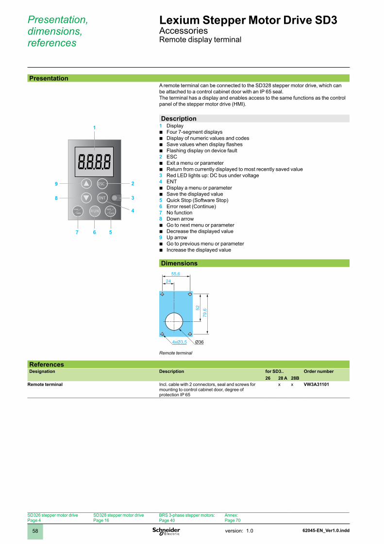
62045-EN_Ver1.0.inddversion: .058
Presentation, dimensions, references
Lexium Stepper Motor Drive SD3 AccessoriesRemote display terminal
PresentationA remote terminal can be connected to the SD328 stepper motor drive, which can be attached to a control cabinet door with an IP 65 seal.The terminal has a display and enables access to the same functions as the control panel of the stepper motor drive (HMI).
Description1 Display
Four 7-segment displaysDisplay of numeric values and codesSave values when display flashesFlashing display on device fault
2 ESCExit a menu or parameterReturn from currently displayed to most recently saved value
3 Red LED lights up: DC bus under voltage4 ENT
Display a menu or parameterSave the displayed value
5 Quick Stop (Software Stop)6 Error reset (Continue)7 No function8 Down arrow
Go to next menu or parameterDecrease the displayed value
9 Up arrowGo to previous menu or parameterIncrease the displayed value
bbbb
bb
bb
bb
bb
Dimensions
24
4xØ3,5
55,6
5279
,6
Ø36
Remote terminal
ReferencesDesignation Description for SD3.. Order number
26 28 A 28BRemote terminal Incl. cable with 2 connectors, seal and screws for
mounting to control cabinet door, degree of protection IP 65
x x VW3A31101
8.8.8.8
RUN Halt
Contxxxx
xxxx
ESC
ENT 3
1
8
4
7 6 5
29
SD326 stepper motor drivePage 4
SD328 stepper motor drivePage 6
BRS 3-phase stepper motors:Page 40
Annex:Page 70
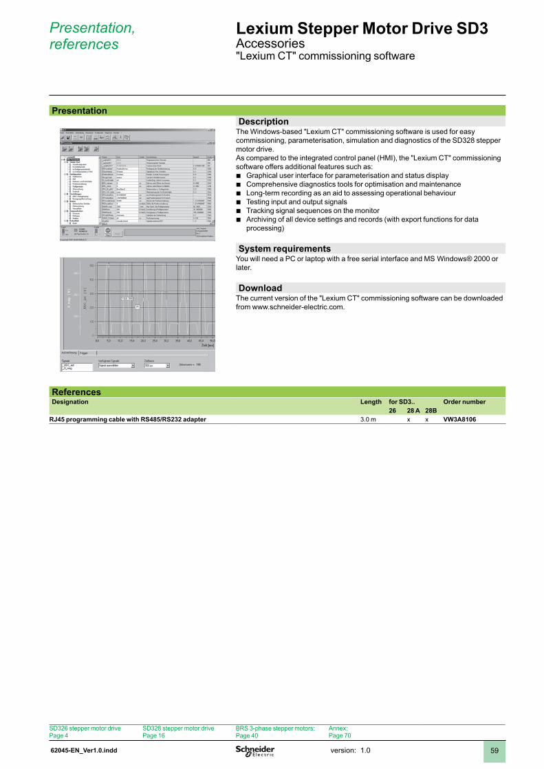
62045-EN_Ver1.0.indd version: .0 59
Presentation, references
Lexium Stepper Motor Drive SD3 Accessories"Lexium CT" commissioning software
PresentationDescription
The Windows-based "Lexium CT" commissioning software is used for easy commissioning, parameterisation, simulation and diagnostics of the SD328 stepper motor drive. As compared to the integrated control panel (HMI), the "Lexium CT" commissioning software offers additional features such as:
Graphical user interface for parameterisation and status displayComprehensive diagnostics tools for optimisation and maintenanceLong-term recording as an aid to assessing operational behaviourTesting input and output signalsTracking signal sequences on the monitorArchiving of all device settings and records (with export functions for data processing)
bbbbbb
System requirementsYou will need a PC or laptop with a free serial interface and MS Windows® 2000 or later.
DownloadThe current version of the "Lexium CT" commissioning software can be downloaded from www.schneider-electric.com.
ReferencesDesignation Length for SD3.. Order number
26 28 A 28BRJ45 programming cable with RS485/RS232 adapter 3.0 m x x VW3A8106
SD326 stepper motor drivePage 4
SD328 stepper motor drivePage 6
BRS 3-phase stepper motors:Page 40
Annex:Page 70

62045-EN_Ver1.0.inddversion: .060
Dimensions, references
Lexium Stepper Motor Drive SD3 AccessoriesMounting plate
DimensionsThe mounting plate is used for mounting the SD3 to a DIN rail.
37,9 77,5
43,
6
Mounting plate
ReferencesDesignation Description for SD3.. Order number
26 28 A 28BMounting plate For mounting to DIN rail x x x VW3A11851
SD326 stepper motor drivePage 4
SD328 stepper motor drivePage 6
BRS 3-phase stepper motors:Page 40
Annex:Page 70
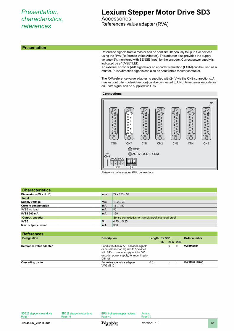
62045-EN_Ver1.0.indd version: .0 6
Presentation, characteristics, references
Lexium Stepper Motor Drive SD3 AccessoriesReferences value adapter (RVA)
Reference signals from a master can be sent simultaneously to up to five devices using the RVA (Reference Value Adapter). This adapter also provides the supply voltage (5V, monitored with SENSE lines) for the encoder. Correct power supply is indicated by a "5VSE" LED.An external encoder (A/B signals) or an encoder simulation (ESIM) can be used as a master. Pulse/direction signals can also be sent from a master controller.
The RVA reference value adapter is supplied with 24 V via the CN9 connections. A master controller (pulse/direction) can be connected to CN6. An external encoder or an ESIM signal can be supplied via CN7.
Connections
OFF
CN6 CN5CN4CN3CN2CN1CN7
S1CN9
CN80VDC
ACTIVE (CN1...CN5)
5VSE
41 32 5
1
8
9
15
1
8
9
15
1
8
9
15
1
8
9
15
1
8
9
15
1
8
9
15
8
1
15
9
24VDC
M3
Reference value adapter RVA, connections
CharacteristicsDimensions (W x H x D) mm 77 x 35 x 37Input
Supply voltage Vc 9.2 ... 30Current consumption mA 5 ... 505VSE no load mA 505VSE 300 mA mA 50Output, encoder Sense-controlled, short-circuit-proof, overload-proof
5VSE Vc 4.75 ... 5.25Max. output current mA 300
ReferencesDesignation Description Length for SD3.. Order number
26 28 A 28BReference value adapter For distribution of A/B encoder signals
or pulse/direction signals to 5 devices with 24 Vc power supply unit for 5 Vc encoder power supply; for mounting to DIN rail
x x VW3M3101
Cascading cable For reference value adapter VW3M30
0.5 m x x VW3M8211R05
Presentation
SD326 stepper motor drivePage 4
SD328 stepper motor drivePage 6
BRS 3-phase stepper motors:Page 40
Annex:Page 70
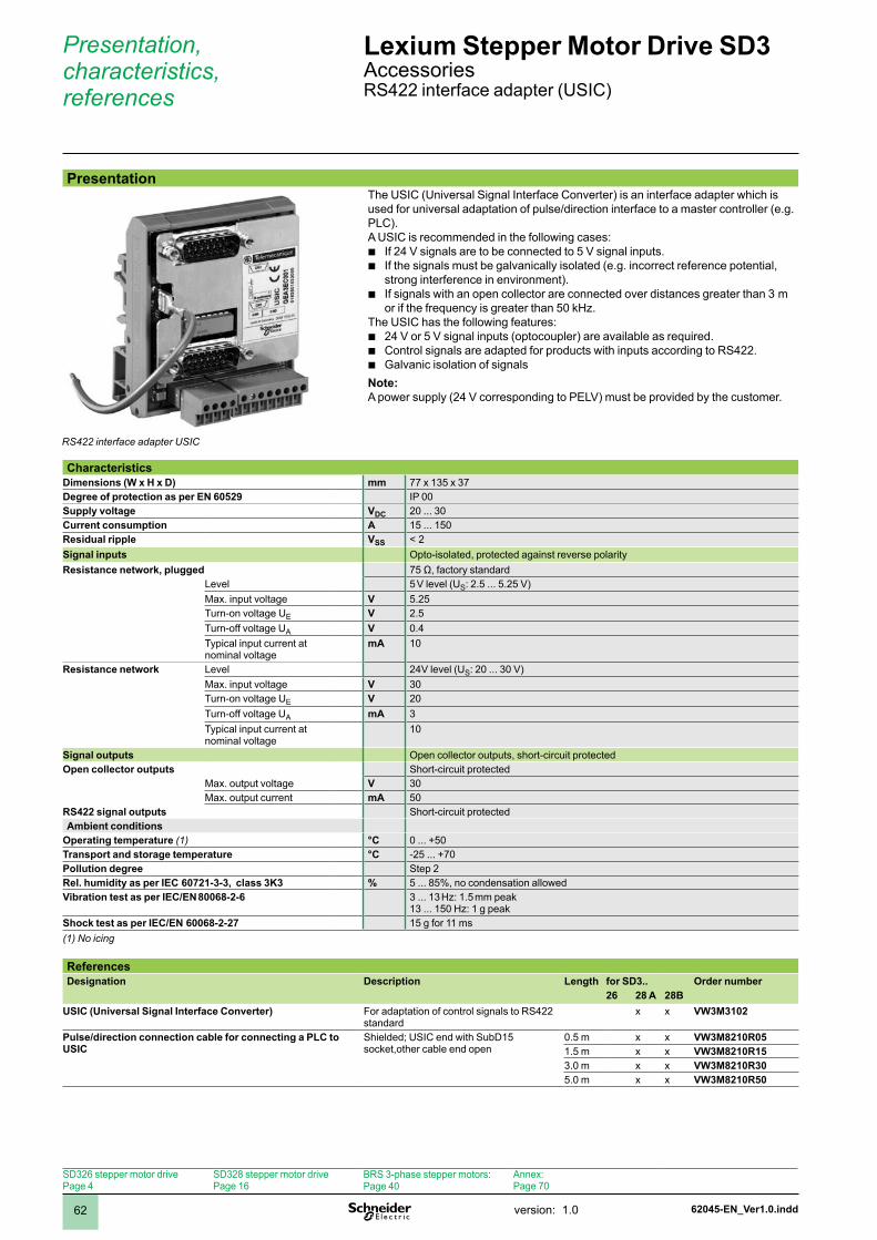
62045-EN_Ver1.0.inddversion: .062
Presentation, characteristics, references
Lexium Stepper Motor Drive SD3 AccessoriesRS422 interface adapter (USIC)
PresentationThe USIC (Universal Signal Interface Converter) is an interface adapter which is used for universal adaptation of pulse/direction interface to a master controller (e.g. PLC).A USIC is recommended in the following cases:
If 24 V signals are to be connected to 5 V signal inputs.If the signals must be galvanically isolated (e.g. incorrect reference potential, strong interference in environment).If signals with an open collector are connected over distances greater than 3 m or if the frequency is greater than 50 kHz.
The USIC has the following features:24 V or 5 V signal inputs (optocoupler) are available as required.Control signals are adapted for products with inputs according to RS422.Galvanic isolation of signals
Note: A power supply (24 V corresponding to PELV) must be provided by the customer.
bb
b
bbb
CharacteristicsDimensions (W x H x D) mm 77 x 35 x 37Degree of protection as per EN 60529 IP 00Supply voltage VDC 20 ... 30Current consumption A 5 ... 50Residual ripple VSS < 2Signal inputs Opto-isolated, protected against reverse polarityResistance network, plugged 75 Ω, factory standard
Level 5 V level (US: 2.5 ... 5.25 V)Max. input voltage V 5.25Turn-on voltage UE V 2.5Turn-off voltage UA V 0.4 Typical input current at nominal voltage
mA 0
Resistance network Level 24- V level (US: 20 ... 30 V) Max. input voltage V 30Turn-on voltage UE V 20Turn-off voltage UA mA 3 Typical input current at nominal voltage
0
Signal outputs Open collector outputs, short-circuit protectedOpen collector outputs Short-circuit protected
Max. output voltage V 30Max. output current mA 50
RS422 signal outputs Short-circuit protectedAmbient conditions
Operating temperature (1) °C 0 ... +50Transport and storage temperature °C -25 ... +70Pollution degree Step 2Rel. humidity as per IEC 60721-3-3, class 3K3 % 5 ... 85%, no condensation allowedVibration test as per IEC/EN 80068-2-6 3 ... 13 Hz: 1.5 mm peak
13 ... 150 Hz: 1 g peakShock test as per IEC/EN 60068-2-27 5 g for ms(1) No icing
ReferencesDesignation Description Length for SD3.. Order number
26 28 A 28BUSIC (Universal Signal Interface Converter) For adaptation of control signals to RS422
standardx x VW3M3102
Pulse/direction connection cable for connecting a PLC to USIC
Shielded; USIC end with SubD15 socket,other cable end open
0.5 m x x VW3M8210R05.5 m x x VW3M8210R153.0 m x x VW3M8210R305.0 m x x VW3M8210R50
RS422 interface adapter USIC
SD326 stepper motor drivePage 4
SD328 stepper motor drivePage 6
BRS 3-phase stepper motors:Page 40
Annex:Page 70
62045-EN_Ver1.0.indd version: .0 63
Presentation
GBX planetary gearbox
In many cases the axis controller requires the use of a planetary gearbox for adjustment of speed of rotation and torque; the accuracy required by the application must be maintained.
To meet these requirements, Schneider Electric has decided to use the Neugart GBX planetary gears which are specially tuned to the BRS stepper motors. This planetary gearbox features lifetime lubrication. GBX planetary gears are easy to install and operate.
The planetary gears are – depending on the power of the stepper motors – available in four sizes (GBX 60 ... GBX160) and with ten gear ratios (3:1 ... 25:1) (see table below).
The values for the continuous torque and the peak torque at standstill available at the output shaft are calculated by multiplying the characteristic values of the motor by the gear ratio and the efficiency of the gearing (0.96 or 0.94 depending on the gear ratio).
The following table shows the optimum combination of BRS stepper motor and GBX planetary gearbox.
Presentation Lexium Stepper Motor Drive SD3 AccessoriesGBX planetary gearboxes
BRS stepper motor and GBX planetary gearbox combinationsStepper motor (1) Gear ratio
3:1 4:1 5:1 8:1 9:1 12:1 15:1 16:1 20:1 25:1BRS368W13 (W = 8 mm, Z = 38 mm)
GBX 60 GBX 60 GBX 60 GBX 60 GBX 60 GBX 60 GBX 60 GBX 60 GBX 60 GBX 60
BRS397W36(W = 12 mm, Z = 60 mm)
GBX 80 GBX 80 GBX 80 GBX 80 GBX 80 GBX 80 GBX 80 GBX 80 GBX 80 GBX 80
BRS39AW36(W = 12 mm, Z = 60 mm)
GBX 80 GBX 80 GBX 80 GBX 80 GBX 80 GBX 80 GBX 80 GBX 80 GBX 80 GBX 80
BRS39BW46(W = 14 mm, Z = 60 mm)
GBX 80 GBX 80 GBX 80 GBX 80 GBX 80 GBX 80 GBX 80 GBX 80 GBX 80 GBX 80
BRS3ACW85 (W = 19 mm, Z = 56 mm)
GBX 120 GBX 120 GBX 120 GBX 120 GBX 120 GBX 120 GBX 120 GBX 120 GBX 120 GBX 120
BRS3ADW85(W = 19 mm, Z = 56 mm)
GBX 120 GBX 120 GBX 120 GBX 120 GBX 120 GBX 120 GBX 120 GBX 120 GBX 120 GBX 160
(1) GBX planetary gears can be mounted to stepper motors with the specified shaft version (W) and the specified centring collar (Z).
GBX 80 For these combinations, you must check that the application will not exceed the maximum output torque of the gearbox.
SD326 stepper motor drivePage 4
SD328 stepper motor drivePage 6
BRS 3-phase stepper motors:Page 40
Annex:Page 70
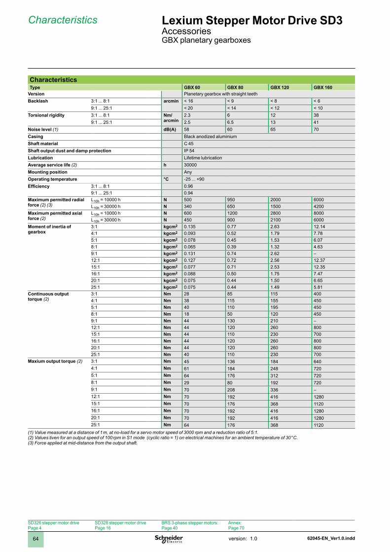
62045-EN_Ver1.0.inddversion: .064
CharacteristicsType GBX 60 GBX 80 GBX 120 GBX 160
Version Planetary gearbox with straight teethBacklash 3: ... 8: arcmin < 6 < 9 < 8 < 6
9: ... 25: < 20 < 4 < 2 < 0Torsional rigidity 3: ... 8: Nm/
arcmin2.3 6 2 38
9: ... 25: 2.5 6.5 3 4Noise level (1) dB(A) 58 60 65 70Casing Black anodized aluminiumShaft material C 45Shaft output dust and damp protection IP 54Lubrication Lifetime lubricationAverage service life (2) h 30000Mounting position AnyOperating temperature °C -25 ... +90Efficiency 3: ... 8: 0.96
9: ... 25: 0.94Maximum permitted radial force (2) (3)
L0h = 0000 h N 500 950 2000 6000L0h = 30000 h N 340 650 500 4200
Maximum permitted axial force (2)
L0h = 0000 h N 600 200 2800 8000L0h = 30000 h N 450 900 200 6000
Moment of inertia of gearbox
3: kgcm2 0.35 0.77 2.63 2.44: kgcm2 0.093 0.52 .79 7.785: kgcm2 0.078 0.45 .53 6.078: kgcm2 0.065 0.39 .32 4.639: kgcm2 0.3 0.74 2.62 –2: kgcm2 0.27 0.72 2.56 2.375: kgcm2 0.077 0.7 2.53 2.356: kgcm2 0.088 0.50 .75 7.4720: kgcm2 0.075 0.44 .50 6.6525: kgcm2 0.075 0.44 .49 5.8
Continuous output torque (2)
3: Nm 28 85 5 4004: Nm 38 5 55 4505: Nm 40 0 95 4508: Nm 8 50 20 4509: Nm 44 30 20 –2: Nm 44 20 260 8005: Nm 44 0 230 7006: Nm 44 20 260 80020: Nm 44 20 260 80025: Nm 40 0 230 700
Maxium output torque (2) 3: Nm 45 36 84 6404: Nm 6 84 248 7205: Nm 64 76 32 7208: Nm 29 80 92 7209: Nm 70 208 336 –2: Nm 70 92 46 2805: Nm 70 76 368 206: Nm 70 92 46 28020: Nm 70 92 46 28025: Nm 64 76 368 20
(1) Value measured at a distance of 1 m, at no-load for a servo motor speed of 3000 rpm and a reduction ratio of 5:1.(2) Values tiven for an output speed of 100 rpm in S1 mode (cyclic ratio = 1) on electrical machines for an ambient temperature of 30 °C.(3) Force applied at mid-distance from the output shaft.
Characteristics Lexium Stepper Motor Drive SD3 AccessoriesGBX planetary gearboxes
SD326 stepper motor drivePage 4
SD328 stepper motor drivePage 6
BRS 3-phase stepper motors:Page 40
Annex:Page 70
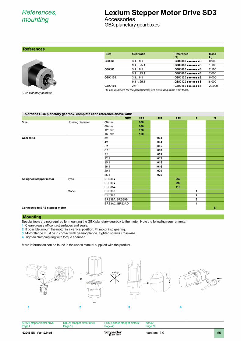
62045-EN_Ver1.0.indd version: .0 65
References, mounting
Lexium Stepper Motor Drive SD3 AccessoriesGBX planetary gearboxes
ReferencesSize Gear ratio Reference
(1)Mass kg
GBX 60 3:... 8: GBX 060 ppp ppp pS 0.9009: ... 25: GBX 060 ppp ppp pS .00
GBX 80 3:... 8: GBX 080 ppp ppp pS 2.009: ... 25: GBX 080 ppp ppp pS 2.600
GBX 120 3:... 8: GBX 120 ppp ppp pS 6.0009: ... 25: GBX 120 ppp ppp pS 8.000
GBX 160 25: GBX 160 ppp ppp pS 22.000(1) The numbers for the placeholders are explained in the next table.
To order a GBX planetary gearbox, complete each reference above with: GBX ppp ppp ppp p S
Size Housing diameter 60 mm 06080 mm 08020 mm 12060 mm 160
Gear ratio 3: 0034: 0045: 0058: 0089: 0092: 0125: 0156: 01620: 02025: 025
Assigned stepper motor Type BRS36p 060BRS39p 090BRS3Ap 110
Model BRS368 1BRS397 2BRS39A, BRS39B 3BRS3AC, BRS3AD 4
Connected to BRS stepper motor S
MountingSpecial tools are not required for mounting the GBX planetary gearbox to the motor. Note the following requirements:
Clean grease off contact surfaces and seals.If possible, mount the motor in a vertical position. Fit motor into gearing.Motor flange must be in contact with gearing flange. Tighten screws crosswise.Tighten clamping ring with torque spanner.
More information can be found in the user's manual supplied with the product.
1 2 3 4
0+0,0
GBX planetary gearbox
1 2 3 4
SD326 stepper motor drivePage 4
SD328 stepper motor drivePage 6
BRS 3-phase stepper motors:Page 40
Annex:Page 70

62045-EN_Ver1.0.inddversion: .066
Dimensions Lexium Stepper Motor Drive SD3 AccessoriesGBX planetary gearboxes
DimensionsMounting at motor side
GBX c A a1 a2 a3 a4 a5 h g Ø1 Ø2 Ø3 Ø4 Ø5 Ø6 Ø7060 003 ... 008 60 06.5 24.5 47 35 30 2.5 6 5 60 40 h7 4 h7 M5 x 8 52 M5 x 2 63
060 009 ... 025 60 8.5 24.5 59 35 30 2.5 6 5 60 40 h7 4 h7 M5 x 8 52 M5 x 2 63
080 003 ... 008 90 34 33.5 60.5 40 36 4 22.5 6 80 60 h7 20 h7 M6 x 0 70 M6 x 5 00
080 009 ... 025 90 5 33.5 77.5 40 36 4 22.5 6 80 60 h7 20 h7 M6 x 0 70 M6 x 5 00
120 003 ... 008 5 76.5 47.5 74 55 50 5 28 8 5 80 h7 25 h7 M0 x 6 00 M8 x 20 5
120 009 ... 025 5 203.5 47.5 0 55 50 5 28 8 5 80 h7 25 h7 M0 x 6 00 M8 x 20 5
160 025 40 305 64.5 53.5 87 80 8 43 2 60 30 h7 40 h7 M2 x 20 45 M0 x 25 65
4xØ6
a1 a2 a3a4
Ø3
Ø2
Ø1
a5
a
Ø7
g4xØ4
h
Ø5
c
4xØ6
a1 a2 a3a4
Ø3
Ø2
Ø1
a5
a
Ø7
g4xØ4
h
Ø5
c
4xØ6
a1 a2 a3a4
Ø3
Ø2
Ø1
a5
a
Ø7
g4xØ4
h
Ø5
c
4xØ6
a1 a2 a3a4
Ø3
Ø2
Ø1
a5
a
Ø7
g4xØ4
h
Ø5
c
SD326 stepper motor drivePage 4
SD328 stepper motor drivePage 6
BRS 3-phase stepper motors:Page 40
Annex:Page 70
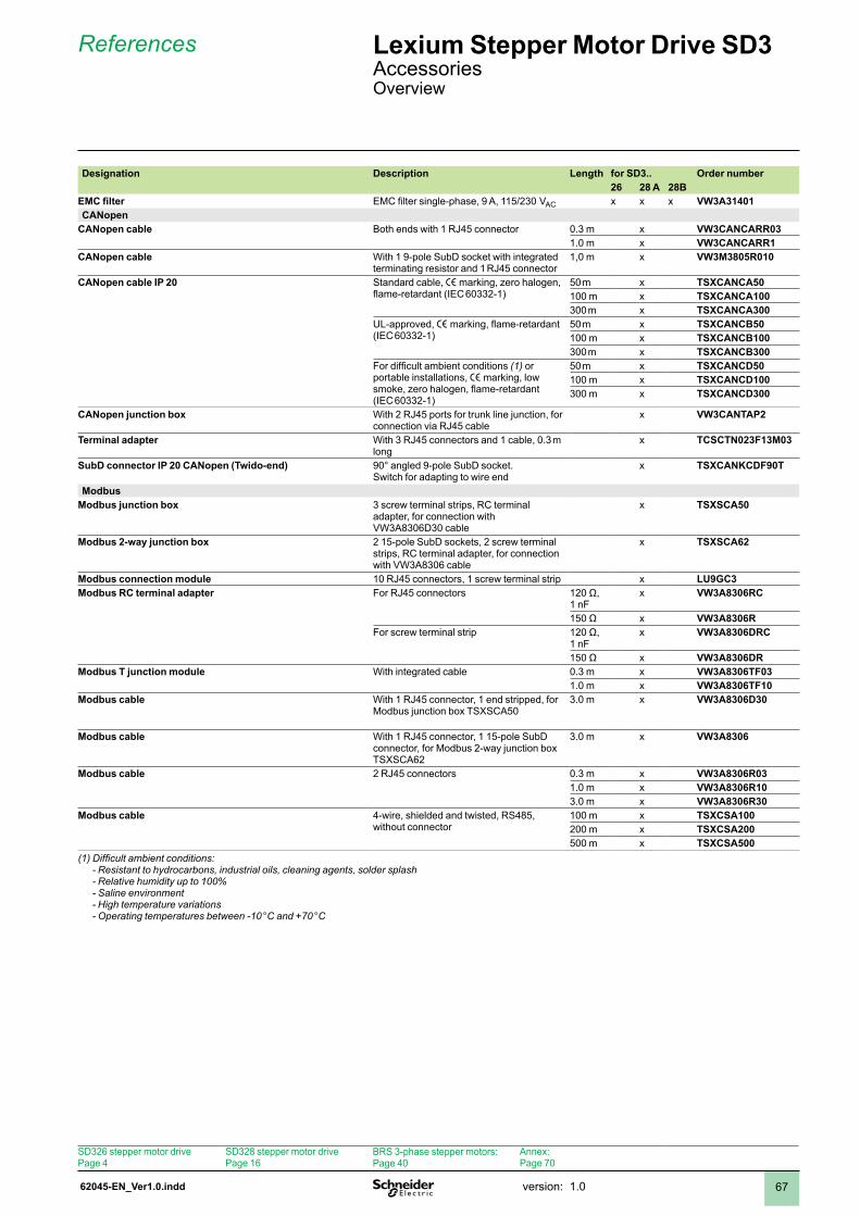
62045-EN_Ver1.0.indd version: .0 67
References Lexium Stepper Motor Drive SD3 AccessoriesOverview
Designation Description Length for SD3.. Order number26 28 A 28B
EMC filter EMC filter single-phase, 9 A, 115/230 VAC x x x VW3A31401CANopen
CANopen cable Both ends with RJ45 connector 0.3 m x VW3CANCARR03.0 m x VW3CANCARR1
CANopen cable With 1 9-pole SubD socket with integrated terminating resistor and RJ45 connector
,0 m x VW3M3805R010
CANopen cable IP 20 Standard cable, e marking, zero halogen, flame-retardant (IEC 60332-1)
50 m x TSXCANCA5000 m x TSXCANCA100300 m x TSXCANCA300
UL-approved, e marking, flame-retardant (IEC 60332-)
50 m x TSXCANCB5000 m x TSXCANCB100300 m x TSXCANCB300
For difficult ambient conditions (1) or portable installations, e marking, low smoke, zero halogen, flame-retardant (IEC 60332-)
50 m x TSXCANCD5000 m x TSXCANCD100300 m x TSXCANCD300
CANopen junction box With 2 RJ45 ports for trunk line junction, for connection via RJ45 cable
x VW3CANTAP2
Terminal adapter With 3 RJ45 connectors and 1 cable, 0.3 m long
x TCSCTN023F13M03
SubD connector IP 20 CANopen (Twido-end) 90° angled 9-pole SubD socket.Switch for adapting to wire end
x TSXCANKCDF90T
ModbusModbus junction box 3 screw terminal strips, RC terminal
adapter, for connection with VW3A8306D30 cable
x TSXSCA50
Modbus 2-way junction box 2 15-pole SubD sockets, 2 screw terminal strips, RC terminal adapter, for connection with VW3A8306 cable
x TSXSCA62
Modbus connection module 0 RJ45 connectors, screw terminal strip x LU9GC3Modbus RC terminal adapter For RJ45 connectors 120 Ω,
nFx VW3A8306RC
150 Ω x VW3A8306RFor screw terminal strip 120 Ω,
nFx VW3A8306DRC
150 Ω x VW3A8306DRModbus T junction module With integrated cable 0.3 m x VW3A8306TF03
.0 m x VW3A8306TF10Modbus cable With RJ45 connector, end stripped, for
Modbus junction box TSXSCA503.0 m x VW3A8306D30
Modbus cable With 1 RJ45 connector, 1 15-pole SubD connector, for Modbus 2-way junction box TSXSCA62
3.0 m x VW3A8306
Modbus cable 2 RJ45 connectors 0.3 m x VW3A8306R03.0 m x VW3A8306R103.0 m x VW3A8306R30
Modbus cable 4-wire, shielded and twisted, RS485, without connector
00 m x TSXCSA100200 m x TSXCSA200500 m x TSXCSA500
(1) Difficult ambient conditions: - Resistant to hydrocarbons, industrial oils, cleaning agents, solder splash - Relative humidity up to 100% - Saline environment - High temperature variations - Operating temperatures between -10 °C and +70 °C
SD326 stepper motor drivePage 4
SD328 stepper motor drivePage 6
BRS 3-phase stepper motors:Page 40
Annex:Page 70
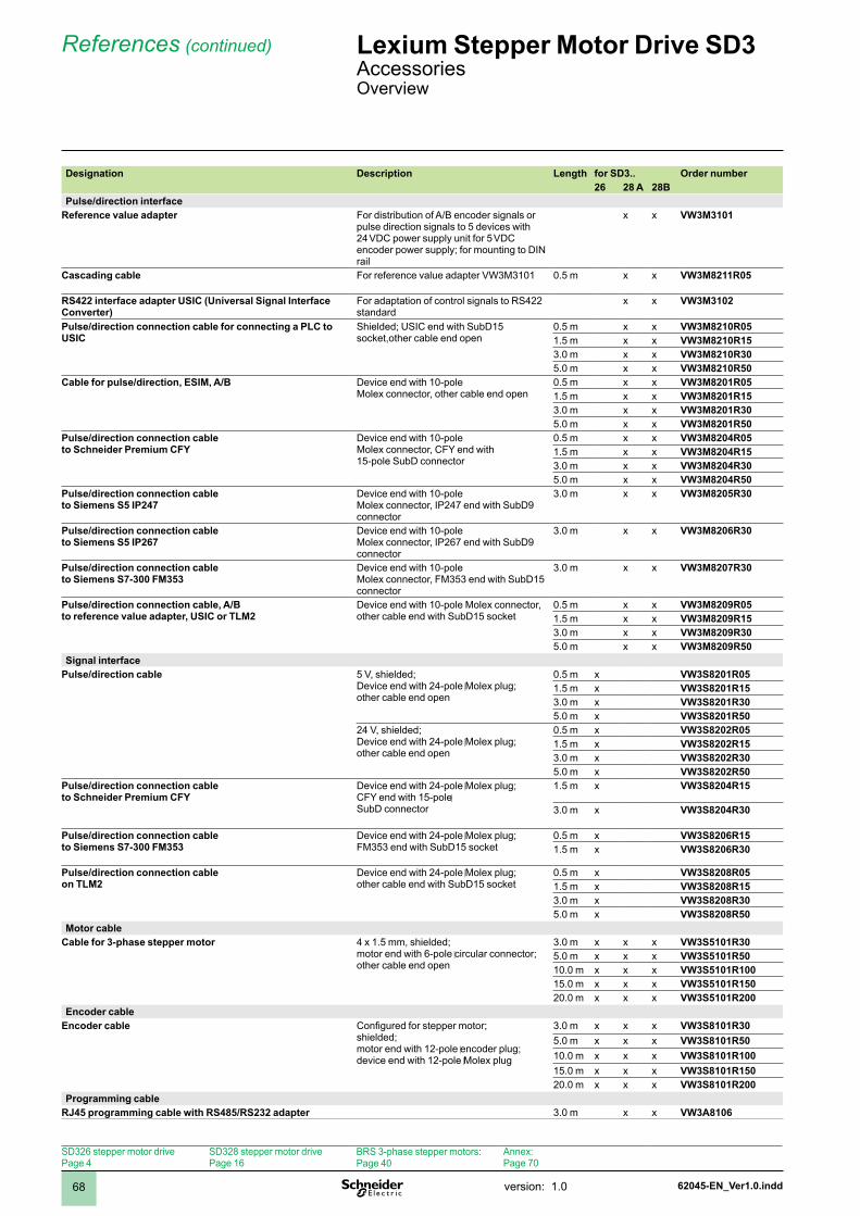
62045-EN_Ver1.0.inddversion: .068
References (continued) Lexium Stepper Motor Drive SD3 AccessoriesOverview
Designation Description Length for SD3.. Order number26 28 A 28B
Pulse/direction interfaceReference value adapter For distribution of A/B encoder signals or
pulse direction signals to 5 devices with 24 VDC power supply unit for 5 VDC encoder power supply; for mounting to DIN rail
x x VW3M3101
Cascading cable For reference value adapter VW3M30 0.5 m x x VW3M8211R05
RS422 interface adapter USIC (Universal Signal Interface Converter)
For adaptation of control signals to RS422 standard
x x VW3M3102
Pulse/direction connection cable for connecting a PLC to USIC
Shielded; USIC end with SubD15 socket,other cable end open
0.5 m x x VW3M8210R05.5 m x x VW3M8210R153.0 m x x VW3M8210R305.0 m x x VW3M8210R50
Cable for pulse/direction, ESIM, A/B Device end with 0-pole Molex connector, other cable end open
0.5 m x x VW3M8201R05.5 m x x VW3M8201R153.0 m x x VW3M8201R305.0 m x x VW3M8201R50
Pulse/direction connection cable to Schneider Premium CFY
Device end with 0-pole Molex connector, CFY end with 15-pole SubD connector
0.5 m x x VW3M8204R05.5 m x x VW3M8204R153.0 m x x VW3M8204R305.0 m x x VW3M8204R50
Pulse/direction connection cable to Siemens S5 IP247
Device end with 0-poleMolex connector, IP247 end with SubD9 connector
3.0 m x x VW3M8205R30
Pulse/direction connection cable to Siemens S5 IP267
Device end with 0-pole Molex connector, IP267 end with SubD9 connector
3.0 m x x VW3M8206R30
Pulse/direction connection cable to Siemens S7-300 FM353
Device end with 0-pole Molex connector, FM353 end with SubD15 connector
3.0 m x x VW3M8207R30
Pulse/direction connection cable, A/B to reference value adapter, USIC or TLM2
Device end with 0-pole Molex connector, other cable end with SubD15 socket
0.5 m x x VW3M8209R05.5 m x x VW3M8209R153.0 m x x VW3M8209R305.0 m x x VW3M8209R50
Signal interfacePulse/direction cable 5 V, shielded;
Device end with 24-pole Molex plug;other cable end open
0.5 m x VW3S8201R05.5 m x VW3S8201R153.0 m x VW3S8201R305.0 m x VW3S8201R50
24 V, shielded;Device end with 24-pole Molex plug;other cable end open
0.5 m x VW3S8202R05.5 m x VW3S8202R153.0 m x VW3S8202R305.0 m x VW3S8202R50
Pulse/direction connection cableto Schneider Premium CFY
Device end with 24-pole Molex plug;CFY end with 15-pole SubD connector
.5 m x VW3S8204R15
3.0 m x VW3S8204R30
Pulse/direction connection cableto Siemens S7-300 FM353
Device end with 24-pole Molex plug;FM353 end with SubD15 socket
0.5 m x VW3S8206R15.5 m x VW3S8206R30
Pulse/direction connection cableon TLM2
Device end with 24-pole Molex plug;other cable end with SubD15 socket
0.5 m x VW3S8208R05.5 m x VW3S8208R153.0 m x VW3S8208R305.0 m x VW3S8208R50
Motor cableCable for 3-phase stepper motor 4 x .5 mm, shielded;
motor end with 6-pole circular connector;other cable end open
3.0 m x x x VW3S5101R305.0 m x x x VW3S5101R500.0 m x x x VW3S5101R1005.0 m x x x VW3S5101R15020.0 m x x x VW3S5101R200
Encoder cableEncoder cable Configured for stepper motor;
shielded;motor end with 12-pole encoder plug;device end with 12-pole Molex plug
3.0 m x x x VW3S8101R305.0 m x x x VW3S8101R500.0 m x x x VW3S8101R1005.0 m x x x VW3S8101R15020.0 m x x x VW3S8101R200
Programming cableRJ45 programming cable with RS485/RS232 adapter 3.0 m x x VW3A8106
SD326 stepper motor drivePage 4
SD328 stepper motor drivePage 6
BRS 3-phase stepper motors:Page 40
Annex:Page 70
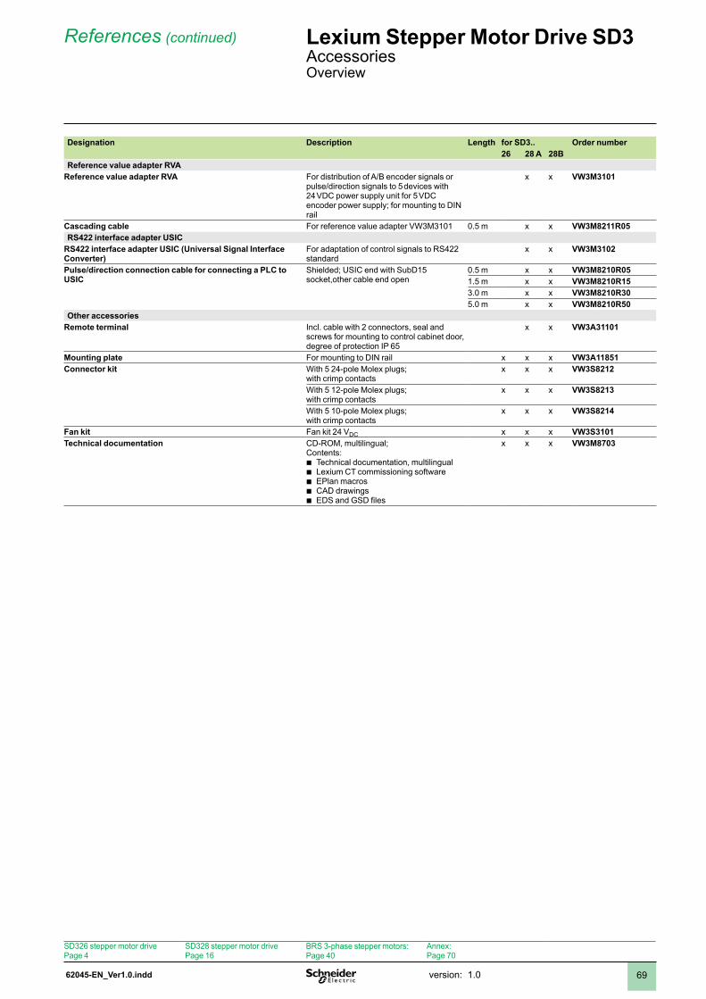
62045-EN_Ver1.0.indd version: .0 69
References (continued) Lexium Stepper Motor Drive SD3 AccessoriesOverview
Designation Description Length for SD3.. Order number26 28 A 28B
Reference value adapter RVAReference value adapter RVA For distribution of A/B encoder signals or
pulse/direction signals to 5 devices with 24 VDC power supply unit for 5 VDC encoder power supply; for mounting to DIN rail
x x VW3M3101
Cascading cable For reference value adapter VW3M30 0.5 m x x VW3M8211R05RS422 interface adapter USIC
RS422 interface adapter USIC (Universal Signal Interface Converter)
For adaptation of control signals to RS422 standard
x x VW3M3102
Pulse/direction connection cable for connecting a PLC to USIC
Shielded; USIC end with SubD15 socket,other cable end open
0.5 m x x VW3M8210R05.5 m x x VW3M8210R153.0 m x x VW3M8210R305.0 m x x VW3M8210R50
Other accessoriesRemote terminal Incl. cable with 2 connectors, seal and
screws for mounting to control cabinet door, degree of protection IP 65
x x VW3A31101
Mounting plate For mounting to DIN rail x x x VW3A11851Connector kit With 5 24-pole Molex plugs;
with crimp contactsx x x VW3S8212
With 5 2-pole Molex plugs;with crimp contacts
x x x VW3S8213
With 5 0-pole Molex plugs;with crimp contacts
x x x VW3S8214
Fan kit Fan kit 24 VDC x x x VW3S3101Technical documentation CD-ROM, multilingual;
Contents: Technical documentation, multilingualLexium CT commissioning softwareEPlan macrosCAD drawingsEDS and GSD files
bbbbb
x x x VW3M8703
SD326 stepper motor drivePage 4
SD328 stepper motor drivePage 6
BRS 3-phase stepper motors:Page 40
Annex:Page 70
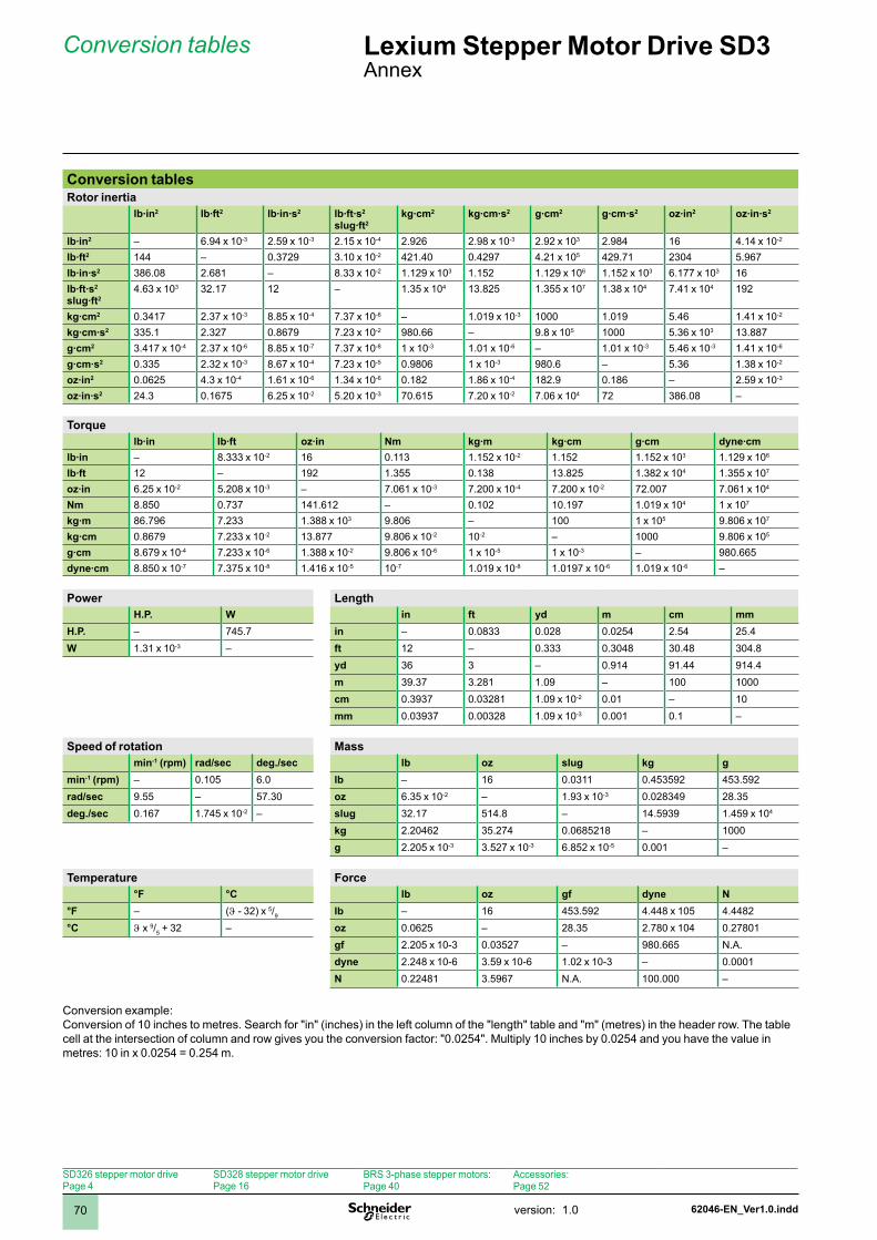
2
1
3
4
5
6
7
8
9
10
2
1
3
4
5
6
7
8
9
10
62046-EN_Ver1.0.inddversion: .070
Conversion tablesRotor inertia
lb·in2 lb·ft2 lb·in·s2 lb·ft·s2 slug·ft2
kg·cm2 kg·cm·s2 g·cm2 g·cm·s2 oz·in2 oz·in·s2
lb·in2 – 6.94 x 0-3 2.59 x 0-3 2.5 x 0-4 2.926 2.98 x 0-3 2.92 x 03 2.984 6 4.4 x 0-2
lb·ft2 44 – 0.3729 3.0 x 0-2 42.40 0.4297 4.2 x 05 429.7 2304 5.967lb·in·s2 386.08 2.68 – 8.33 x 0-2 .29 x 03 .52 .29 x 06 .52 x 03 6.77 x 03 6lb·ft·s2 slug·ft2
4.63 x 03 32.7 2 – .35 x 04 3.825 .355 x 07 .38 x 04 7.4 x 04 92
kg·cm2 0.347 2.37 x 0-3 8.85 x 0-4 7.37 x 0-6 – .09 x 0-3 000 .09 5.46 .4 x 0-2
kg·cm·s2 335. 2.327 0.8679 7.23 x 0-2 980.66 – 9.8 x 05 000 5.36 x 03 3.887g·cm2 3.47 x 0-4 2.37 x 0-6 8.85 x 0-7 7.37 x 0-8 x 0-3 .0 x 0-6 – .0 x 0-3 5.46 x 0-3 .4 x 0-6
g·cm·s2 0.335 2.32 x 0-3 8.67 x 0-4 7.23 x 0-5 0.9806 x 0-3 980.6 – 5.36 .38 x 0-2
oz·in2 0.0625 4.3 x 0-4 .6 x 0-6 .34 x 0-6 0.82 .86 x 0-4 82.9 0.86 – 2.59 x 0-3
oz·in·s2 24.3 0.675 6.25 x 0-2 5.20 x 0-3 70.65 7.20 x 0-2 7.06 x 04 72 386.08 –
Torquelb·in lb·ft oz·in Nm kg·m kg·cm g·cm dyne·cm
lb·in – 8.333 x 0-2 6 0.3 .52 x 0-2 .52 .52 x 03 .29 x 06
lb·ft 2 – 92 .355 0.38 3.825 .382 x 04 .355 x 07
oz·in 6.25 x 0-2 5.208 x 0-3 – 7.06 x 0-3 7.200 x 0-4 7.200 x 0-2 72.007 7.06 x 04
Nm 8.850 0.737 4.62 – 0.02 0.97 .09 x 04 x 07
kg·m 86.796 7.233 .388 x 03 9.806 – 00 x 05 9.806 x 07
kg·cm 0.8679 7.233 x 0-2 3.877 9.806 x 0-2 0-2 – 000 9.806 x 05
g·cm 8.679 x 0-4 7.233 x 0-6 .388 x 0-2 9.806 x 0-6 x 0-5 x 0-3 – 980.665dyne·cm 8.850 x 0-7 7.375 x 0-8 .46 x 0-5 0-7 .09 x 0-8 .097 x 0-6 .09 x 0-6 –
Power LengthH.P. W in ft yd m cm mm
H.P. – 745.7 in – 0.0833 0.028 0.0254 2.54 25.4W .3 x 0-3 – ft 2 – 0.333 0.3048 30.48 304.8
yd 36 3 – 0.94 9.44 94.4m 39.37 3.28 .09 – 00 000cm 0.3937 0.0328 .09 x 0-2 0.0 – 0mm 0.03937 0.00328 .09 x 0-3 0.00 0. –
Speed of rotation Massmin-1 (rpm) rad/sec deg./sec lb oz slug kg g
min-1 (rpm) – 0.05 6.0 lb – 6 0.03 0.453592 453.592rad/sec 9.55 – 57.30 oz 6.35 x 0-2 – .93 x 0-3 0.028349 28.35deg./sec 0.67 .745 x 0-2 – slug 32.7 54.8 – 4.5939 .459 x 04
kg 2.20462 35.274 0.068528 – 000g 2.205 x 0-3 3.527 x 0-3 6.852 x 0-5 0.00 –
Temperature Force°F °C lb oz gf dyne N
°F – (ϑ - 32) x 5/9 lb – 6 453.592 4.448 x 05 4.4482°C ϑ x 9/5 + 32 – oz 0.0625 – 28.35 2.780 x 04 0.2780
gf 2.205 x 0-3 0.03527 – 980.665 N.A.dyne 2.248 x 0-6 3.59 x 0-6 .02 x 0-3 – 0.000N 0.2248 3.5967 N.A. 00.000 –
Conversion example:Conversion of 10 inches to metres. Search for "in" (inches) in the left column of the "length" table and "m" (metres) in the header row. The table cell at the intersection of column and row gives you the conversion factor: "0.0254". Multiply 10 inches by 0.0254 and you have the value in metres: 0 in x 0.0254 = 0.254 m.
Conversion tables Lexium Stepper Motor Drive SD3Annex
SD326 stepper motor drivePage 4
SD328 stepper motor drivePage 6
BRS 3-phase stepper motors:Page 40
Accessories:Page 52
2
1
3
4
5
6
7
8
9
10
2
1
3
4
5
6
7
8
9
10
62046-EN_Ver1.0.indd version: .0 7
Lexium Stepper Motor Drive SD3Annex
SD326 stepper motor drivePage 4
SD328 stepper motor drivePage 6
BRS 3-phase stepper motors:Page 40
Accessories:Page 52
2
1
3
4
5
6
7
8
9
10
2
1
3
4
5
6
7
8
9
10
62046-EN_Ver1.0.inddversion: .072
Lexium Stepper Motor Drive SD3Annex
SD326 stepper motor drivePage 4
SD328 stepper motor drivePage 6
BRS 3-phase stepper motors:Page 40
Accessories:Page 52


Schneider Electric Motion Deutschland GmbH & Co. KG
Breslauer Str. 777933 LahrGermany
Due to evolution of standards and equipment, the characteristics indicated in texts and images of this document do not constitute a commitment on our part without confirmation.Design: Schneider ElectricPhotos: Schneider ElectricPrinted by: ???
ART. June/2008
???
www.schneider-electric.com