Renewable and Sustainable Energy Reviews - … and Sustainable Energy Reviews journal homepage:...
21
Contents lists available at ScienceDirect Renewable and Sustainable Energy Reviews journal homepage: www.elsevier.com/locate/rser Active power filter (APF) for mitigation of power quality issues in grid integration of wind and photovoltaic energy conversion system Wajahat Ullah Tareen a, ⁎ , Saad Mekhilef a, ⁎ , Mehdi Seyedmahmoudian b , Ben Horan b a Power Electronics and Renewable Energy Research Laboratory (PEARL), Department of Electrical Engineering, Faculty of Engineering, University of Malaya, Kuala Lumpur 50603, Malaysia b School of Engineering, Deakin University, Waurn Ponds, VIC 3216, Australia ARTICLE INFO Keywords: Active filter Power quality Grid-connected system Transformerless inverter Renewable energy integration Reduced-switch-count inverter ABSTRACT The deep integration of renewable energy resources, including solar photovoltaic (PV) and wind turbine (WT) energy, mainly depend on the inexpensive technological improvement of global emissions and the precise techniques for power quality. Grid-connected inverters act as key components in distributed generation systems for cutting-edge technology. The inverter connects the renewable energy sources and power distribution network systems for the conversion of power. In grid-connected systems, several current and voltage harmonics affect the system performances. Likewise, highly unstable devices coupled with the growing demand for nonlinear loads and renewable energy resources influence the power networks and systems performance in terms of power quality. The effective solutions to these problems are passive filters (PFs), static var generators, and active power filters (APFs). However, the use of PFs in a high-power system increases its cost, size, and weight. This study aims to assess the most advanced APFs by reducing the number of power switches and focus on the reduction of cost, size, and weight of grid-connected inverters. Several studies compared and evaluated reduced-switch-count APF inverter topologies, such as AC–AC, back-to-back, and common leg, under the single-phase and three-phase systems. Recently, cost-effective solutions to reduce the number of components, transformerless inverters, multilevel and multifunctional inverters based on the APF in PV, and wind energy conversion systems have been greatly explored. The current techniques and their limitations for developing advanced inverter-based devices for renewable energy systems are discussed with justifications. Therefore, this review would potentially help industrial researchers improve power quality in PV and WT energies and power distribution network systems. 1. Introduction The demand for electricity in the modern industrial world is rapidly increasing, from household utilities to commercial industries. Integration of distributed energy resources (DER) [1], such as solar photovoltaic (PV) systems [2], wind energy conversion system (WECS) [3], fuel cells [4], distributed power generation systems (DPGSs) [5], and storage devices [6], improves the reliability and electric power quality while decreasing the loss of power distribution or transmission networks. PV and wind power are the two leading renewable energies resources for reducing the continuous burden on the national power grid and the global environment. In the power utilization industry, an increasing number of renew- able energy devices, as well as linear and nonlinear loads, are being introduced; these devices include the nonlinear rectifier and static var compensator (SVC), which affect daily life [7]. Integrated grid PV and wind energy systems produce certain harmonics, heat, and other complicated power-quality issues, thereby affecting the supply current and voltage sinusoidal waveform spectra [8] in terms of lower system efficiency, overheating of transformers, increased malfunction of motors and cables, increased power loss, necessity of protection devices [9], and the limited life period of wind turbine generator [10] and solar PV modules [11]. The power output is stochastic and the energy resource is intermittent. Therefore, proper current harmonic and power-quality mitigation methods are required to enhance the relia- bility of the renewable grid-connected system. Various solutions have been proposed to solve the power-quality issues [12], such as un- balanced systems, load balance, injected harmonics, excessive neutral current, reactive power burden, and the network interference in electrical systems. Filters are traditionally used in grid-integrated systems in combination with passive filters (PFs) [13] against series harmonics. As such, PFs have limited use because of issues, including limited filtering, specific load ranges, fixed compensation, larger sizes, parallel and series negative resonance between grids, and filter http://dx.doi.org/10.1016/j.rser.2016.11.091 Received 13 January 2016; Received in revised form 14 September 2016; Accepted 4 November 2016 ⁎ Corresponding authors. Renewable and Sustainable Energy Reviews 70 (2017) 635–655 Available online 31 December 2016 1364-0321/ © 2016 Elsevier Ltd. All rights reserved. MARK
Transcript of Renewable and Sustainable Energy Reviews - … and Sustainable Energy Reviews journal homepage:...

Contents lists available at ScienceDirect
Renewable and Sustainable Energy Reviews
journal homepage: www.elsevier.com/locate/rser
Active power filter (APF) for mitigation of power quality issues in gridintegration of wind and photovoltaic energy conversion system
Wajahat Ullah Tareena,⁎, Saad Mekhilefa,⁎, Mehdi Seyedmahmoudianb, Ben Horanb
a Power Electronics and Renewable Energy Research Laboratory (PEARL), Department of Electrical Engineering, Faculty of Engineering, University ofMalaya, Kuala Lumpur 50603, Malaysiab School of Engineering, Deakin University, Waurn Ponds, VIC 3216, Australia
A R T I C L E I N F O
Keywords:Active filterPower qualityGrid-connected systemTransformerless inverterRenewable energy integrationReduced-switch-count inverter
A B S T R A C T
The deep integration of renewable energy resources, including solar photovoltaic (PV) and wind turbine (WT)energy, mainly depend on the inexpensive technological improvement of global emissions and the precisetechniques for power quality. Grid-connected inverters act as key components in distributed generation systemsfor cutting-edge technology. The inverter connects the renewable energy sources and power distributionnetwork systems for the conversion of power. In grid-connected systems, several current and voltage harmonicsaffect the system performances. Likewise, highly unstable devices coupled with the growing demand fornonlinear loads and renewable energy resources influence the power networks and systems performance interms of power quality. The effective solutions to these problems are passive filters (PFs), static var generators,and active power filters (APFs). However, the use of PFs in a high-power system increases its cost, size, andweight. This study aims to assess the most advanced APFs by reducing the number of power switches and focuson the reduction of cost, size, and weight of grid-connected inverters. Several studies compared and evaluatedreduced-switch-count APF inverter topologies, such as AC–AC, back-to-back, and common leg, under thesingle-phase and three-phase systems. Recently, cost-effective solutions to reduce the number of components,transformerless inverters, multilevel and multifunctional inverters based on the APF in PV, and wind energyconversion systems have been greatly explored. The current techniques and their limitations for developingadvanced inverter-based devices for renewable energy systems are discussed with justifications. Therefore, thisreview would potentially help industrial researchers improve power quality in PV and WT energies and powerdistribution network systems.
1. Introduction
The demand for electricity in the modern industrial world is rapidlyincreasing, from household utilities to commercial industries.Integration of distributed energy resources (DER) [1], such as solarphotovoltaic (PV) systems [2], wind energy conversion system (WECS)[3], fuel cells [4], distributed power generation systems (DPGSs) [5],and storage devices [6], improves the reliability and electric powerquality while decreasing the loss of power distribution or transmissionnetworks. PV and wind power are the two leading renewable energiesresources for reducing the continuous burden on the national powergrid and the global environment.
In the power utilization industry, an increasing number of renew-able energy devices, as well as linear and nonlinear loads, are beingintroduced; these devices include the nonlinear rectifier and static varcompensator (SVC), which affect daily life [7]. Integrated grid PV andwind energy systems produce certain harmonics, heat, and other
complicated power-quality issues, thereby affecting the supply currentand voltage sinusoidal waveform spectra [8] in terms of lower systemefficiency, overheating of transformers, increased malfunction ofmotors and cables, increased power loss, necessity of protection devices[9], and the limited life period of wind turbine generator [10] and solarPV modules [11]. The power output is stochastic and the energyresource is intermittent. Therefore, proper current harmonic andpower-quality mitigation methods are required to enhance the relia-bility of the renewable grid-connected system. Various solutions havebeen proposed to solve the power-quality issues [12], such as un-balanced systems, load balance, injected harmonics, excessive neutralcurrent, reactive power burden, and the network interference inelectrical systems. Filters are traditionally used in grid-integratedsystems in combination with passive filters (PFs) [13] against seriesharmonics. As such, PFs have limited use because of issues, includinglimited filtering, specific load ranges, fixed compensation, larger sizes,parallel and series negative resonance between grids, and filter
http://dx.doi.org/10.1016/j.rser.2016.11.091Received 13 January 2016; Received in revised form 14 September 2016; Accepted 4 November 2016
⁎ Corresponding authors.
Renewable and Sustainable Energy Reviews 70 (2017) 635–655
Available online 31 December 20161364-0321/ © 2016 Elsevier Ltd. All rights reserved.
MARK

impedance [14–17]; these issues cause the rapid decay of passivecomponents [18].
According to surveys of grid-integrated systems, such as PVinverters [19] and wind energy systems [20], the power-quality issuesare addressed by the use of more advanced filtering technologies, suchas a static synchronous compensator, active power filter (APF),dynamic voltage regulator, multilevel inverter, power-monitoring sys-tem, and unified power quality conditioner (UPQC). However, theshunt APF (SAPF) is the most dominant and liberal solution againstproblems of power quality, with reactive power and current harmonicscompensation [21–24]. The filter performance depends on inverterparameters, control schemes, and reference current detection techni-ques [25]. A reference current signal is extracted by harmonic loaddetection techniques, such as the instantaneous power theory (p–qtheory), fundamental positive sequence methods, and synchronousdetection [26], for effective control of the APFs.
Two international standards, IEEE-519 [27,28] and IEC 61000-3-2[29], provide a boundary for all power utility companies in the designand operation of their systems. With the increasing load demand, theAPF rating [30] also increases with the accumulating system capacityand cost. As a solution, hybrid APFs (HAPF) are used to configure thePF with SAPF [31]. In HAPF operation, both filters are controlled, suchthat the low-order harmonics are eliminated by SAPF operation [32],whereas the higher frequency harmonics are canceled by PF. APFsreduce the load current disturbances, which improve current andvoltage harmonic compensation. Fig. 1 illustrates the hierarchicalstructure of renewable energy with power sources and energy storageresources in a power distribution network [33–36].
Recently, several HAPF topologies use transformers and an ex-cessive number of passive components as key tools to manage the filter
size, cost, and weight optimization. However, the transformerlesstopologies achieve a safer and higher system efficiency, smallervolumetric size, cheaper cost, and more compact structures as com-pared with older transformer-based topologies. The elimination of atransformer generates several problems, including efficiency degrada-tion, safety complications, leakage current, and the installation of a
Fig. 1. Hierarchical structure of renewable power sources and grid-connected invertersin a power distribution network.
Nomenclature
vs (a, b, c) three-phase source voltageis (a, b, c) three-phase instantaneous source currentiL (a, b, c) three-phase load currentiF (a, b, c) three-phase filter compensator currentCf Capacitor filterLf Inductor filterLs Source-side inductorLAC Load-side inductorVdc DC-link voltageCdc DC-link capacitorDER Distributed energy resourcesPV Photo voltaicWECS Wind energy conversion systemDPGS Distributed power generation systemPQ Power qualityWT Wind turbinesWTG Wind turbine generatorDVR Dynamic voltage regulatorML-MFI Multilevel multifunctional inverterVOC Voltage oriented controlGHG Greenhouse gassesRE Renewable energyPWM pulse width modulationSPWM Sinusoidal pulse width modulationSAPF shunt active power filterHAPF Hybrid active power filterPF Passive filterVSC Voltage Source ConverterTHD Total Harmonic DistortionSRF synchronous-reference-framePLL phase locked loop
UPS uninterruptible power supplyPCC point of common couplingFF Feed-forwardFB Feed-backAC Alternating currentDC Direct currentPI Proportional IntegralP/Q Active and Reactive PowerEMI Electromagnetic interferenceSiC silicon carbideSBD Schottky barrier diodeUSMC Ultra-sparse matrix converterZVS Zero voltage switchingZVT Zero voltage transitionZCT Zero current transitionCMV Common-mode voltageCMC Conventional matrix converterPMGS Permanent magnet synchronous generatorDFIG Doubly fed induction generatorULTC Under Load Tap Changer (ULTC) transformerHERIC High efficient and reliable inverter conceptUPQC Unified power quality conditionerDSTATCOM Distributed static synchronous compensatorsSTATCOM Static synchronous compensatorsSVC Static var compensatorSVG Static var generatorDVR Dynamic voltage restorer,OLTC On-load tap changer,AVC Automatic voltage control,SDBR Series dynamic breaking resistor,TCSC Thyristor controlled series capacitorUPFC Thyristor controlled series capacitor.
W.U. Tareen et al. Renewable and Sustainable Energy Reviews 70 (2017) 635–655
636

resonant circuit. Different power converter combinations shunted atthe point of common coupling work as an interface between the utilityand renewable energy source, depending on the topology structure andmodulation scheme. However, the fluctuating common mode voltageand the absence of leakage current in the PV grid-connected systemcontribute toward the improvement of the system voltage and fre-quency as compared with traditional topologies. A brief comparison ofdifferent transformerless PV inverter topologies is presented inTable 1[37–41]. The total system cost is compares in terms of theswitch count and system efficiency [33] with three issues: the galvanicconnection, grid voltage fluctuation to ground at input poles, and safety[37,42].
Electrical transmission system and loads operate on the AC gridpower [43], whereas the output voltage of renewable energy sourcesoperates on direct current (DC) power. For stand-alone and grid-connected systems, an inverter is the key device required to convert ACpower to DC power. The inverter is mounted from the low-power KWrange to the higher-power MW range [44] to construct the output ACsinusoidal waveform, which is accomplish by the series or parallelcombination of electronic switch devices [45]. Developments in thelarge-scale PV power system and wind generation systems subjectinverters to continuous evolution and make these inverters indispen-sable. Despite the increasing demand, a major issue of inverters is thelarger amount of power switching components, such as insulated gatebipolar transistors (IGBTs) and metal-oxide semiconductor field effecttransistors (MOSFETs). Several pure SAPFs are limited by the use ofhigh-power-rating components to improve the utility power factorcorrection and current harmonic compensation. When connected tothe electrical grid, the increased number of semiconductor switchcomponents produces higher switch losses, which contributes toharmonics in the output voltage waveform, degrades the systemefficiency [46], and causes the overall system performance to deterio-rate [47]. Recently, a reduced switch count has become a cutting-edgesolution in power electronics technology, including power semicon-ductor devices, power conversion circuits, sensors, and control circuits.Despite the importance of component reduction for advancing energyissues, literature on the reduction of switches in APFs is limited.
This in-depth review presents the advances in switch reduction ofAPFs and focuses on the cost, size, and weight reduction of grid-connected inverters. This paper provides a broad and in-depthliterature review to the researchers in the field of reducing devicesand grid-connected PV and wind turbine (WT) energy conversionsystems. Some potential research topics are also included; the reduc-tion of components, transformerless inverters, and multilevel multi-functional inverters (ML-MFI) for APFs in the PV and WECS arediscussed. Different topologies, including single-phase and three-phasesystem classes, are presented, compared with other topologies, andevaluated based on the total harmonic distortion (THD), harmonicmitigation, the active and reactive power compensation, componentratings, advantages, and disadvantages. The review provides a bench-mark for the further development and exploration of other switchreduction techniques that have received little attention from research-ers. This paper is divided into six sections, starting with a briefintroduction in Section 1. Section 2 provides a brief description ofthe grid-connected structure of the PV and WECS, with emphasis onthe power quality issues. Section 3 illustrates the basic classificationand recent advances in SAPF topologies, as well as their maincharacteristics. In Section 4, the performance of these topologies isdiscussed, evaluated and analyzed. The SAPF technologies are alsobriefly compared. Potential further research work is described inSection 5, with concluding remarks in Section 6.
Table
1Com
parison
ofdifferenttran
sformerless
PVinverter
topolog
ies.
H-b
ridge
(unip
olarPW
M)
H-b
ridge
(bip
olarPW
M)
Half-
bridge
HERIC
topology
H5Topology
Half-b
ridge
with
GCC
Casc
adedH-
bridge(n
cells)
NPC
half-
bridge
Flyin
gca
pacito
r(F
C)
NPC
variant
Conerg
yNPC
ActiveNPC
(ANPC)
Inputca
pacito
rs1
12
11
2ɳ
23
42
2In
putca
pacitance
Low
Low
High
Low
Low
Med
ium
Highest
High
High
High
High
High
Switch
es
44
26
54
4ɳ
44
44
6Diodes
00
02
00
02
02
00
Tra
nsistorvoltage
400V
400V
800V
400V
400V
800V
400V/ɳ
400V
400V
400V
400V
400V
Outp
utvoltage
level
32
23
32
2ɳ-1
33
33
3
First
harm
onic
2FSW
FSW
FSW
2FSW
2FW
FSW
2ɳF
SW2F
SW2F
SW2F
SW2F
SW2F
SWEM
Fin
terfere
nce
Low
High
High
Low
Low
High
VeryLow
Low
Low
Low
Low
Low
No.ofM
PPTs
11
11
12
ɳ1
11
11
Leakagecu
rrent
High
Low
Low
est
Low
est
Low
est
Low
est
Med
ium
Low
est
Low
est
Low
est
Low
est
Low
est
W.U. Tareen et al. Renewable and Sustainable Energy Reviews 70 (2017) 635–655
637
2. Mitigation of power quality and distributed generationsystems
2.1. Grid-connected APF-PV inverter
As discussed above, the main aim of installing the PV system at thePCC [48,49] is to improve the operation of power distribution systemsand to generate active power. However, to prevent the additional costof the power circuit, several PV-fed grid interactive topologies com-bined the PV inverter with the additional functionality of SAPF [50], aswell as voltage and reactive power support. The PV inverter injects thecompensating current into the grid to filter the load current harmonics[51–53]. In addition, the inverter uses the active power produced fromthe PV solar energy system. On the other hand, the APF are introducedin the PV system [54,55] to improve the power conversion efficiency,reliability, and current harmonic distortions of the system.
Recently, the ML-MFI has become the most dominant technologyused in the PV grid-integrated electrical power generation systems. Athigh DC-rated voltage, it produces the output waveform in steps withlow harmonic distortion waveform. It easily controls multifunctionalinverter issues such as grid current harmonic and unbalance mitiga-tion, reactive power compensation, control voltage at PCC [56,57] andtransient process in between the PV generator to utility grid during theAPF operation. The ML-MFI topologies are installed in high-rated and
large PV systems because of its advantages, such as low harmonic andpower dissipation and low electromagnetic interference (EMI) outputs.Table 2 summarizes the comparison between the grid-integrated PVinverter topologies [58–60] and the additional functionalities of APFs.In Refs. [61,62], a three-level NPC-MFGCI PV system is controlledmore efficiently with a modified voltage-oriented control and spacevector PWM (SVPWM) technique to provide shunt active filtering,reactive power compensation, and load current balance to the utilitygrid.
SAPF can integrate with the PV grid-connected system for harmo-nic elimination content and reactive power compensation [81] to keepthe DC-link voltage constant. A precise mathematical model is needed[82] for the controllers, thereby making the controllers more indepen-dent from parameter variation. By contrast, energy storage systems,such as batteries, super capacitors, and flywheels, are programmed toovercome the intermittency problem in renewable PV energy systems.The inherent characteristics of the PV systems decreased the powergeneration to 15% per second, thereby affecting the performance of thegrid network. Therefore, the energy storage systems maintain theconstant voltage [83] by reducing voltage fluctuation [84] and main-taining higher PV efficiency [85]. PV systems also help to suppress theharmonic content and regulate the compensating reactive power,thereby enhancing the reliability of the PV grid-integrated system [86].
Table 2Comparison of APFs in grid-inverter topologies.
Ref Topology Modulation/control
Capacity Switchingfrequency(kHz)
No. ofswitches
Trans-former
No. ofdiodes
No. of DCcapacitors
THD (%) PV/DC-linkvoltage
Grid-connectedfunctions
Single-phase System[63] Full bridge SPWM/PI ≤1.5 kVA 20 4 0 2 1@1000uF 3.09 – PV-APF[53] Full bridge Hysteresis 1 kVA 14.2 4 1 0 1@- 2.31 150 V PV-APF[64] Full bridge SPWM/PI ≤1.5 kVA 20 2 0 2 1@940μF 4.5 250 V PV-APF[65] Full bridge SPWM/PI 3 kVA – 4 1 0 – < 5 246 V PV-APF[66] Full bridge SPWM/Lyapunov – 10 4 0 0 – < 5 100 V PV-APF[67] Full bridge SPWM/PI ≤1 kVA – 4 0 1 1@200uF – 14 V PV-APF[68] Full bridge SPWM/repetitive 4 kVA 10 4 0 0 [email protected] 2 400 V PV-APF[69] Full bridge SPWM/PI 1 kVA – 4 0 0 – – – PV-APF[70] Three leg SPWM/PI 1 kVA 18 6 0 1 1@1000uF 3.19 17 V PV-APF[71] HB ZVS SPWM/PI 1 kVA 100/10 6 – – – – – PV-APF
Three-phase System[72] H-bridge SPWM/PI 1.1 kVA 20 6 0 2 1@2200 pF 7.8 400 V PV-APF[73] H-bridge SPWM/PI 10 kVA – 6 0 0 – – – PV-APF[74] H-bridge Hysteresis 150 kVA – 6 1 0 1@5uF 1.29 800 V PV-APF[75] H-bridge SPWM/FLC, PI – – 6 1 0 0 2.5 500 V PV-APF[76] H-bridge SPWM/FLC, PI 20 kVA – 12 1 0 – – – PV-APF[77] ZVI SPWM/FLC, PI 7.5 kVA – 6 0 1 2@1500uF 4.21 100 V–60
VPV-APF
[61] 3 L- NPC SPWM/FLC, PI 1 kVA – 14 0 3 2@3mF – 1100 V PV-APF[78] Four bridge 3D-SVPWM – 10 8 0 0 1@850uF 13 350 V PV-APF[79] Full bridge Hysteresis/LQR – – 12 1 0 1@- < 0.5 3.5 kV PV-APF[80] H-bridge SPWM/FLC, PI 30 kVA 10 12 1 0 2@6600uF – 700 V PV-APF
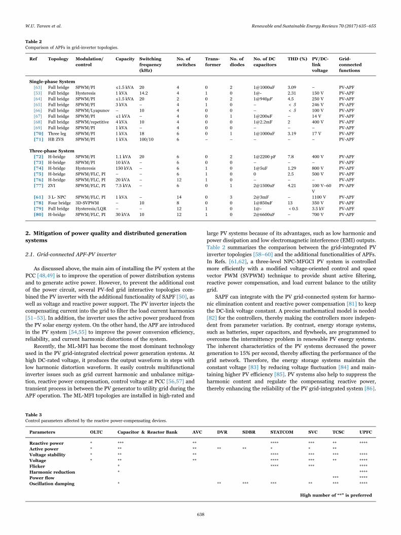
Table 3Control parameters affected by the reactive power-compensating devices.
Parameters OLTC Capacitor & Reactor Bank AVC DVR SDBR STATCOM SVC TCSC UPFC
Reactive power * *** ** **** *** ** ****Active power * ** ** ** ** * * **Voltage stability * ** ** **** *** *** ****Voltage * ** ** **** *** ** ****Flicker * **** *** ****Harmonic reduction * ****Power flow *** ****Oscillation damping * ** *** *** ** *** ****
High number of “*” is preferred
W.U. Tareen et al. Renewable and Sustainable Energy Reviews 70 (2017) 635–655
638

Fig. 2. Classification of APF.
Fig. 3. (a) Shunt APF, (b) series APF, and (c) hybrid APF.
W.U. Tareen et al. Renewable and Sustainable Energy Reviews 70 (2017) 635–655
639

2.2. Grid-connected APF-WE inverter
In recent times, the energy industry is leaning more towardrenewable energy consumption. Wind energy is a more legitimatesource of power, less expensive, and available throughout the years[87]. Compared with fossil fuels and solar energy, wind energy has theadditional advantage of being cost effective, absence of greenhouse gas
emissions, a progressive renewable energy source, accessible andproduction is flexible so energy demand can be met, and moreenvironment friendly at the power distribution network level [88].However, power quality is a complicated issue in grid-connectedWECS.
The high demand for mounting WTs with the main grid [89] affectsthe reactive power, voltage fluctuations, flicker because of switching
Table 4Comparison of APF topologies.
Specific Considerations APF Topology
Shunt Active Filter Series Active Filter Hybrid APF
Circuit configuration Fig. 3(a) Fig. 3(b) Fig. 3(c)
Power rangeSmall scale < 350 W (power ratings below 100 kVA)Medium scale < 350 kW (three-phase systems ranging from 100 kVA to 10 MVA)Large scale < 350 kW (systems with ratings above 10 MVA)
Converter efficiencySmall Lowest (up to 98%)Medium High (up to 98%)Large Highest (up to 98%)Power circuit Minor power loop in PWM-VSI No power loop in PWM-VSI Minor current loop/No current loop in PWM-VSIAPF operates as Current source (CSI) Voltage source (VSI) Both (CSI/VSI)harmonics generating Loads Thyristor/diode rectifier with Inductive
loadDiode rectifier with Capacitive load Thyristor/diode rectifier with Inductive load
Additional function Reactive power compensation, Currentcompensation
AC Voltage regulation, Voltage flickerCompensation
Harmonic compensation/ Harmonic damping/Harmonic isolation
Switching devices IGBTs, MOSFETs, GTO thyristors IGBTs, MOSFETs, GTO thyristors IGBTs, MOSFETs, GTO thyristorsCurrent harmonics ** – ***Reactive power *** – **Load balancing * – –
Neutral current ** – *Voltage harmonics – *** **Voltage regulation * *** **Voltage balancing – *** **Voltage flicker *** ** –
Voltage sag and dips * *** **High number of “*” is preferred
Fig. 4. (a) Shunt APF with shunt PF, (b) series APF with shunt PF, and (c) APF in series with shunt PF.
W.U. Tareen et al. Renewable and Sustainable Energy Reviews 70 (2017) 635–655
640

and during operations, and output voltage and current at the PCC. Thevariable-speed WT operation depends upon the active and reactivepower control and behavior of the nonlinear and unbalanced loads. Inthis aspect, the nonlinear characteristics of power electronic devices[90] generate high THD value current and output voltage, weakeningthe WT generator (WTG) performance [91,92], cause more heat andlow system efficiency, and decrease the life span of WTG [93].Therefore, an appropriate harmonic mitigation and reactive powercompensation technology is necessary to improve the power quality ofwind energy [94] in the grid-connected WECS. A WTG operates at theconstant wind speed to control the permanent magnet synchronousgenerator (PMSG) [95,96] for the APF operation to mitigate thecurrent harmonics A forward modified modulation technique is usedto control the APF system based on different reference signal extractiontechniques [97].
A more advanced variable frequency-based WT system (WTS) [98]operates in the islanding mode to cancel the harmonics and function ofAPF. Through the doubly fed induction generator (DFIG) [99] in thefixed speed, WT used the ability of APF under the islanding mode. Toreduce the converter cost, a reduced-switch-count topology [100–104]for WECS system is installed. A split-capacitor leg is shared betweenthe back-to-back converters at the area of voltage unbalance. Thistopology has decoupling issues between the multipole PMSG and thegrid. In addition, it requires an extra DC-link capacitor, needs a morecomplex control, and faces higher semiconductor stress [105].
In grid-connected WECS, reactive power control and compensationis an important requirement and an essential parameter to the powerdistribution grid. It is essential to maintain the constant voltage profile
of the WTG to control the minimum losses in transferring the reactivepower exchange to the power grid. The under load tap changertransformer is the main device that controls reactive power compensa-tion in the grid. Furthermore, several WT produce limited voltage andreactive power in the coupled induction generator [106]. As a solution,several devices, such as STATCOM [107], SVCs, on-load tap changer(OLTC) and switching capacitors, PWM inverter, and a combination ofcapacitor and inductor [108], are installed with the induction gen-erators. Several devices, such as DBR, OLTC, and manual switchedcapacitor banks, are not capable of overcoming harmonics and voltageflicker. By contrast, the SVC, STATCOM, and DFIG devices improve thestatic and dynamic stability behavior of the reactive power and fixed
Fig. 5. Overview of reduced switch-count inverter topologies in grid application.
Fig. 6. AC–AC inverter topology.
W.U. Tareen et al. Renewable and Sustainable Energy Reviews 70 (2017) 635–655
641

speed wind generators [109]. However, these devices regulate thevoltage balance [110], which helps in increasing the use of the windpower in power grid networks.
Table 3 demonstrates the reactive power compensating devices[111] in grid-connected WECS compared with other parameters [112].The control parameters related to reactive power compensating devicesare as follows: on-load tap changer (OLTC), automatic voltage control(AVC), dynamic voltage restorer (DVR), series dynamic breakingresistor (SBBR), static synchronous compensator (STATCOM), staticVAR compensators (SVC) [113], thyristor-controlled series capacitor(TCSC), and unified power flow controller (UPFC).
3. Classification of grid-tied APF
Generally, the APFs are classified into three categories as depictedin Fig. 2, that is, topology- based type, converter type, and a number ofphases [114]. The topology-based type category is subclassified intothree types: SAPF, series APF, and HAPF. The number of phases(wires) are divided into single-phase (two wires), three-phase (threewires), and three-phase (four wires) systems [115]. The topology-basedcategory is categorized into the shunt, series, and hybrid configurationas shown in Fig. 3. The series APF reduces the negative sequence ofvoltage harmonic propagation caused by the system resonance [116],which improves the electrical utilities of terminal voltage. In the energyindustry, the increasing demand of high load current generates currentrating loss and filter size limitation. Table 4 shows the comparison ofthree APF topologies [117,118].
Three different combinations of HAPF circuit are illustrated inFig. 4. The series APF with shunt PF offers high impedance for theharmonic isolation in the medium voltage system as depicted inFig. 4(c). It delivers reactive power, voltage harmonic compensation,and balancing of the three-phase voltages [119–121]. On the otherhand, SAPF alongside shunt PF is used to eliminate the fundamentalreactive power and high order load current harmonics as shown inFig. 4(b). In high-power application, both systems provide reactivepower compensation with less switching cost [122,123]. In medium-and high-voltage applications, the constant DC-link voltage and gridfundamental voltage are maintained by using series APF together withshunt PF as depicted in Fig. 4(a), which effectively reduces the systemvolumetric size and cost [21,124].
4. Comparative study on reduced-switch-count APF invertertopologies and their control
This study reviews the three best reduced-switch-count APF con-figurations in detail, namely, AC–AC inverter, back-to-back inverter,and common-leg inverter topologies. The complete cycle of reducedswitch count integrated into grid application, starting from twelve tothree switches, is explained in Fig. 5.
4.1. AC–AC inverter topology
In AC–AC inverter topology, the pulse width modulation voltagesource inverter [24] is connected in parallel with the DC-link capacitoras illustrated in Fig. 6. Single-phase two-wire, three-phase three-wire,and three-phase four-wire are the respective sections of the AC–ACinverter configuration.
4.1.1. Single-phase (two-wire) APFsIn high-power application, the diode-clamped, flying-capacitor
clamped, and switch-clamped inverters use several semiconductorswitches. A single-phase six-switch reduced-count VSI without boththe clamping diodes and flying capacitors achieves harmonic elimina-tion, reactive power compensation, and inverter losses [125]. In fivelevels, AC terminal voltage uses eight-switch power converter [126] toeliminate the need for a transformer. To reduce voltage stress, twoflying capacitors are used in correspondence with flying-capacitor-clamped and switch-clamped inverters to reduced volumetric size,weight, and cost [127,128]. Four different configurations of AC–ACinverter topology are summarized in Table 5, discussing the number of
Table 5Comparison of reduced-switch-count AC–AC inverter topology.
Author [129] [130] [131] [132]
Topology One leg Three leg Two leg Two legModulation/control SPWM/EF-DF SPWM PI/VPI current control SPWM/PICapacity (kVA) 2.5 5 1.5 1.8Switching frequency (kHz) 6 3.2 10 20Conventional topology 6 12 6 9Reduced switch count 3 9 4 6No. of legs 1 3 2 2No. of filter inductors 1 3 3 6No. of filter capacitors + 0 0 6No. of transmission line inductors + 3 3 6Grid voltage (V) + 208 127 220No. of DC capacitors 3@2200uF 1@2350uF 2@2000uF 1@4700uF
THD % 60–1% 64.74–1% 24.4–1.89% (RL) 36–3% (no load)30.2–1.97% (RLC) 43–5.6% (with load)
Estimated efficiency High Medium Medium LowDC-link voltage (Vdc) 200 V 320 V 420 V 120 VGrid interface 3transistorVSI 6 transistor VSI 4 transistor VSI 3 transistor VSI
+ Not reported, ~ Estimated Value
Fig. 7. Nine-switch AC–AC inverter APF circuit.
W.U. Tareen et al. Renewable and Sustainable Energy Reviews 70 (2017) 635–655
642

switches, the filter inductors, and different system parameters, such asTHD, DC-link voltage, switching frequency, and estimated efficiency.
The bootstrap technique used in three-level current source inverterneeds an isolated multiple DC power supply and an electrolyticcapacitor. All the circuit switches are connected to common source orcommon emitter to reduce the gate-drive power supplies into a singlepower source. the electrolytic capacitor usually has short life spanbecause of its larger size [133]. Regardless, a single-phase three-levelconverter provides low harmonic content as compared with a two-levelconverter. The reduction of switches creates three limitations, that is,the need for an isolated DC source, curtailed modularity, and fault-tolerant capabilities [134,135]; reducing the component voltage ratingand improving the system power factor effectively eases the systemcost, switching loss, and switching state redundancies.
To reduce the system cost, a transformerless single-phase line-interactive uninterruptible power supply (UPS) system is presented in[136–138] to control the DC current and AC current component for thecharging and discharging the battery bank. A DC capacitor is connectedin series with a three-leg power converter to operate as a buffer inbetween the switch set, filter capacitor set, filter inductor set, batteryset, and decoupling circuits [139,140].
4.1.2. Three-phase (three-wire) APFsA three-phase APF system consists of four-switch converter and
eight-switch converter configurations. It uses a two-arm bridge inverterand a DC-link capacitor to eliminate the harmonics, reactive powerproblems, and subsequent variations in the DC-link voltage [141–146],aside from removing the current sensors in several applicationsbecause of common mode current strategy [146]. The only constraintin high-power applications of the three-phase APF is that it requireshigh-voltage stress switches because of the large turns on resistance. Asoft switching converter technique is used to reduce one-half of DC busvoltage and to increase the total output power [147].
The two-clamping diodes, four MOSFETs, one flying capacitor, andmagnetic cores reduce the PWM controller volumetric size and costcompared with the conventional three-level converter. By controllingthe output voltage for leading and lagging switching operation [148], atthe secondary side, two center-tapped rectifiers reduce the currentrating of the rectifier diodes, output filter inductors, and transformerwindings, which result in reducing switch voltage stress, zero voltageswitching (ZVS), and load current sharing.
Three-phase conventional matrix converter requires eighteen IGBTswitches with complex switching scheme. Fifteen switches with re-duced-count IGBT switch converter is presented in [149]. Presenting abetter reduced switch count, a unidirectional power flow twelve IGBTswitches is designed in an ultra-sparse matrix converter [150].
Overcoming the limitation of three-leg nine-switch inverter [130] asdepicted in Fig. 7, the improved two-leg six-switch inverter is presentedin [132]. Fig. 8 demonstrates an HAPF topology connected to a three-phase load without using the matching transformer consisting of a two-
leg six-switch reduced inverter connected in series with two passive LCfilters. Tuned at different harmonic frequencies, it provides bettercompensation than both the conventional HAPF topology and thethree-phase VSI topology.
Another pair of reduced-switch-count dual-leg six-switches and thesingle-leg three-switch leg structure topologies are connected to a twoindividual single-phase loads [129,151]. Moreover, the single-leginverter operates as a two half-bridge inverters with minimum achiev-able three switches split capacitors technique as depicted in Fig. 5(three-switch inverter topology). Both systems operate independentlyas a two full-bridge and half-bridge inverters connected with single-phase and three-phase critical loads.
4.1.3. Three-phase (four-wire) APFsTo control and compare common mode space voltage, a four-switch
scalar PWM vector control method is used by contrast with thestandard six-switch three-phase inverter [152]. In the three-phasefour-wire system, a neutral current circulates beside the reactive power,load current harmonics, and unbalance current. The unbalancedcurrent is caused by the negative and zero-sequence current compo-nents. To compensate, a three-phase four-wire (3P4W) SAPF isdesigned for the multiple power-quality problems in three differentconfigurations, that is, split capacitor (2C), four-leg (4-leg), and three-H (3HB) bridge structure for nonlinear loads [152].
In general, all the three-phase current-controlled VSI-PWM con-verters are twelve or eight switches [153,154], but in the proposeddesign, it uses six switches with two split DC-link capacitors shared byboth the rectifier and inverter [155–158]. The DC-link capacitor legacts as neutral point connection for reducing the number of switches.To minimize the undesired negative effect and zero-sequence current inthe four-wire APF system, a zigzag transformer is used. An interleavedinverter is proposed to cancel the triggered effect of power transmis-sion lines, nonlinear loads, asymmetrically phased load, and powerharmonic current quality [154–156]. The interleaved inverter gener-ates higher switching losses than the conventional two-level inverter interms of DC-link capacitor losses [157]. Five-level and three-levelinverter circuit consists of a reduced number of switches in theinduction motor drive as parallel to the conventional cascading two-level and three-level neutral-point clamped (NPC) inverters. To over-come the problems of bearing current, shaft voltage, early motorfailure, and common-mode voltage (CMV) variation, a DC voltagecontrol and CMV elimination method [159] is adopted.
An alternative concept discussed is the combination of the diodeclamp-type topology with a flying capacitor-type topology; a four-switch converter replaces the twelve-switch converter with lessernumber of diodes [160]. The operating limits in the semi-bridgedrectifier system require a tradeoff between current distortion andswitching ripple [161]. By doubling the switching frequency, thistradeoff and dead time distortion is improved. ZVS converter uses softswitching technique to reduce the number of power switches and
Fig. 8. Six-switch AC–AC inverter APF circuit.
Fig. 9. Parallel inverter topology.
W.U. Tareen et al. Renewable and Sustainable Energy Reviews 70 (2017) 635–655
643

output current ripple. To balance the two input capacitor voltage, athree DC–DC circuit is designed to reduce the three-level diodeclamped with two flying capacitors [162].
4.2. Back-to-back inverter topology
Fig. 9 illustrates the three-phase three-wire back-to-back invertertopology. Both inverters are connected back-to-back with the commonDC-link capacitor. The main advantage of this configuration is that itimproves the APF compensation capability.
4.2.1. Single-phase (two-wire) APFsThe dual-leg six switches operate similarly to the two full-bridge
inverters for two single-phase load. Without a matching transformer,the single converter and maximum power flow strain the systemperformance. As a solution, a reduced-switch-count universal APF isdesigned to convert the single-phase into a three-phase system [163]. Atransient time delay occurs in a half-bridge UPS system because ofpower failure [164,165]. To improve the system response, a reducedswitch count of two and three-leg UPS system is presented in [166–169]. In offline UPS system, a simple winding is added in series withthe common transformer to eliminate the switches [170]. An improvedswitch-reduced three-leg inverter structure is presented in [171] tocontrol one leg as a boost converter to boost the DC-voltage, whereasthe other two legs operate as a full bridge inverter. It operates as anactive filter in normal mode and battery charger in the backupoperating mode. Three different back-to-back inverter configurationsare evaluated based on reduced switch count and detailed in Table 6.
To strengthen this observation, another reduced half-bridge UPSconfiguration with eight switches including four-switch converter andfour-switch inverter was used. Also, it eliminates the isolation trans-former because of the common input and output neutral point [175].As presented in [176–178], reduced number of switch count eliminatesthe need for circuit breakers and static switches, as compared with theconventional line-interactive or online UPS schemes.
4.2.2. Three-phase (three-wire) APFsA dual HAPF inverter topology consists of two power converters in
a back-to-back configuration, sharing a common DC-link capacitor asdepicted in Fig. 10. The feedforward and feedback control is adoptedfor switching operation. In high-dynamic load systems, larger capaci-
Table 6Comparison of reduced-switch-count back-to-back inverter topology.
Author [172] [173] [174]
Topology H-bridge H-bridge Full bridgeModulation/control SPWM/PI/Feedforward and feedback SPWM/PI SPWM/PI/Feedforward and feedbackCapacity 3 kW 3.3 kVA 15 kVASwitching frequency (kHz) 550 Hz and 20 kHz 550 Hz and 20 kHz 12.6 kHzConventional topology 12 12 12Reduced switch count 8 8 12No. of legs 4 4 6No. of filter inductors 5 6 6No. of filter capacitors 5 6 6No. of transmission line inductors 9 6 6Grid voltage (V) 110 110 300No. of DC capacitors 1@4700uF 2@3300uF 2 @ 4.4mF
THD (%) 4.70% 0.03% 1.26%1.11%23.50%
Estimated efficiency Medium High LowDC-link voltage (Vdc) 26 1500 400Grid interface 4 transistor VSI 4 transistor VSI 6 transistor VSI
+ Not reported, ~ Estimated Value
Fig. 10. Twelve switch parallel inverter APF circuit.
Fig. 11. Eight-switch parallel inverter APF circuit.
Fig. 12. Common-leg inverter topology.
W.U. Tareen et al. Renewable and Sustainable Energy Reviews 70 (2017) 635–655
644

tors and DC bus voltage are needed to maintain the larger stabilitymargin to keep less voltage stress across each capacitor. A splitcapacitor (B4) topology is adopted [179] with low cost and losses viathe limitation of voltage balancing across the DC-link capacitor. As asolution, the third phase is connected to the neutral midpoint of splitcapacitor legs, which reduces the twelve-switch power converters toeight-switch configuration.
Presenting a better reduced-switch-count topology, the third phaseis connected to the negative pole of the DC link [172,180] intense somelimitation of split capacitor topology as depicted in Fig. 11. Despitecomplex control and hardware design limitation, it improves thesystem reliability, lowers cost, and preserves low-voltage stress acrossthe DC capacitor.
Upon further investigation, the LC PF is tuned at 550 Hz toeliminate the lower-order harmonics and maintains the DC-linkvoltage constant. The higher-order LC PF is tuned at 750 kHz toeliminate high-level harmonics. A single current sensor is used toconnect the current source feedforward control and voltage sourcefeedback control for active filtering [174]. Both controls provide asteady-state and dynamic response for harmonic mitigation.
A dual four-switch reduced count in each bridge inverter isproposed as compare with the conventional twelve-switch dual-bridgeinverter [181,182]. To improve harmonic compensation and keep thegrid in stable operation, a load sharing and frequency sharing is donewith and without the redundancy in both the filters. The common modevoltage and circulating current at the DC-link capacitor generatesnumerous problems, that is, premature motor bearing failures, voltagefluctuations at DC side, limited power rating components, and EMI. Tostop the zero sequence, which is the current circulating betweeninverters, separate DC capacitors or transformers are installed [180].In line-interactive UPS topology [183], series-parallel power convertersare connected in bidirectional three-leg and two-leg configurations[179]. By adding three more switches to the unidirectional three-phaseseven-switch resonant inverter, a bi-directional power flow is achieved[184] to operate at zero voltage and high-frequency AC link.
4.2.3. Three-phase (four-wire) APFsAnother reduced UPQC system is presented in [185], which is
achieved by connecting the neutral terminal to the negative end of theDC capacitor. The proposed neutral-clamped UPQC system reduces thenumber of components [186], DC-link voltage, average switching
frequency, and THD in source current. For the independent controlof each leg, a capacitor voltage balancing is needed for shunt and seriesinverters, increasing the size and cost of the system. A three-phasevoltage source converter distributed static synchronous compensatorsand T-connected transformer (Scott-T transformer) are installed toreduce the system size. To match the DC-link voltage of APF system,supplementary capacitors are installed in series with a commoncapacitor and inductor.
4.3. Common-leg inverter topology
Fig. 12 illustrates the three-phase three-wire common-leg invertertopology in back-to-back configuration. The circuit is designed bysharing the common DC-link capacitor via single- or double-leg sharingbetween the APF rectifier and inverter. Usually, the common legswitches operate during the rectifier and inverter operations. Single-phase (two-wire) and three-phase (three-wire) configurations arediscussed below.
4.3.1. Single-phase (two-wire) APFsTwo DC-link five-leg and six-leg configurations are designed in
parallel to a single-phase two-wire APF system via single-leg invertersharing. It includes a coupling inductor and DC-link capacitors[187,188] to reduce the system components rating. A universal APFconsists of shared leg between the half bridge and full bridge invertersfor voltage and current harmonic compensation. A parallel seriesinjection transformer is used as a source for power factor control [189].
Table 7Comparison of reduced-switch-count common-leg inverter topology.
Author [193] [194] [195]
Topology Four leg, Three leg, Five leg Five leg Six legModulation/control SPWM SPWM SPWM/PICapacity ~1.5 kVA ~1.5 kVA 5 kVASwitching frequency (kHz) 5 10 12Conventional topology + 12 12Reduced switch count 8, 6, 10 10 12No. of legs 4, 3, 5 5 6No. of filter inductors + 3 12No. of transmission line inductors 3 + 6Grid voltage (V) 60 100 400No. of DC capacitors 2@1000uF 2@2200uF [email protected]
THD (%) 0.8% (8 switches) 1.54% (1st experiment) 27–2%0.6% (6 switches) 0.8% (2nd experiment)
Power factor [PF] + 0.997 +
Estimated efficiency High Medium Low0.84 (1st experiment)0.9 (2nd experiment)
DC-link voltage (Vdc) 100 200 250Grid interface 2 transistor VSI, 2 transistor VSI, 4 transistor VSI 4 transistor VSI 12 transistor VSI
+ Not reported, ~ Estimated Value
Fig. 13. Twelve-switch common-leg inverter APF circuit.
W.U. Tareen et al. Renewable and Sustainable Energy Reviews 70 (2017) 635–655
645

Table 7 summarizes the comparison of three common-leg H-bridgetopologies. The six-switch three-arm bridge voltage regulator reducesswitching devices with low-cost AC capacitors. It controls unity powerfactor, sinusoidal input current, output voltage regulation, and bidirec-tional power flow [190]. A single-phase three-leg converter shares a legbetween the source and load. It reduces the six-switch three-legconverter into a four-switch two-leg converter structure [191,192].
A single-phase online UPS system provides high efficiency, highpower, and quick response to voltage disturbances. A common leg isshared between the rectifier and inverter to provide the bidirectionalcurrent flow. The first rectifier leg is used to charge the battery bank,the third inverter leg is used to control the output voltage, and themiddle leg is used for controlling the line frequency [196]. Thecommon leg reduces the number of switches at low-power losses,low-cost structure, and reactive power control.
4.3.2. Three-phase (three-wire) APFsA total of nine switches are installed on a three-leg converter circuit,
but the middle leg is shared between the rectifier and the invertercircuits [193]. Input and output power is delivered from the middleswitches. Quasi DC link through a two constant frequency and variablefrequency mode provides unity power factor, sinusoidal input, andoutput waveform. A Two-level twelve-switch converter as depicted inFig. 13 contributes to cutting down manufacturing cost as comparedwith the matrix eighteen-switch converters. Nine-switch convertersproduce the same AC voltage level with an oversized DC-link capacitor,which overstresses the semiconductor switches. IGBT devices requirehigher switching ratings and generate higher losses compared withback-to-back twelve-switch converter, along with limitations such aslimited amplitude sharing and phase shift in the output terminal [194].
A single auxiliary switch replaces the two independent auxiliaryswitches to improve the power density of the DC–DC converter. A softswitching with zero voltage transition and zero current transitiontechnique is adopted alongside high switching losses and electromag-netic interferences [197,198].
In another single-phase to three-phase AC motor drive system,multiple legs connected between the grid and load are shared. They arereduced to eight switches in a four-leg configuration. Both theconverters are based on reduced switch as compared with the ten-switch configuration by sharing the single leg [195,199–201] asdepicted in Fig. 14.
Different four-leg, five-leg, and six-leg converters with controlledgate-drive circuit, diodes, and power supplies are reduced by sharingthe common leg. It increases the common-leg current and reduces theDC voltage [202–204], which improves system losses, fault errortolerance, installation size, switch, and capacitor current rating[205,206].
Two voltage-source APFs are connected to the power line throughcommon-mode coils and DC-link capacitor to reduce the size of passivecomponents [207–209]. The common mode coils replace the isolationtransformer, which provides smaller volumetric-size inductors.
A phase-leg averaging technique is used to reduce the size and costof the system without using any passive components in both theindividual converters. To eliminate the passive LC filter, the control isdesigned with space-vector modulation through a high-bandwidthcontrol loop to suppress the circulating current [210].
5. Analysis and discussion
5.1. Reduced-switch-count inverters
Based on the above analysis, a comparison among the varioustransformerless and reduced–switch-count grid-connected invertertopologies has been summarized in Table 8.
It is noticed that to produce AC-voltage amplitudes in back-to-backtopology, a much larger DC-link capacitor and DC voltage is needed.This high voltage generates switching losses because of overstressacross the semiconductor switches. To overcome this problem, z-sourcenetwork and discontinuous modulation scheme are implemented[211]. By contrast, the B8 converter configuration practices eightswitches with shared split DC link [200]. By sharing a common singleDC bus between two individual converters, the B8 converter creates alarge DC voltage variation in the value DC link and lower AC voltage inthe output. However, no fundamental current flows through DC link ifboth the system is functioning and synchronized at the same frequency.On the other hand, to overcome the B8 converter limitation, a five-legconverter is introduced by sharing the fifth-phase leg between the twoconverter interface [212]. Roughly, no large DC variation is observed infundamental voltage, but it has the limitation of the common frequencyimposition in between the two AC-interfaced systems, includingapplications like series-shunt power conditioners and adjustablepowered speed drives.
Recently, the evolution of SAPF in grid-connected and renewableenergy conversion system became important because of power-quality-related problems. Over the last years, several conventional andadvanced topologies and control methods have been documented forcapacities, harmonics mitigation, reactive power compensation, andauxiliary functionalities. Table 9 summarizes the conclusions andparameters based on the recently developed APF topologies describedin Section 4. Each topology is evaluated and compared with each otherto select low-cost, efficient, and suitable configurations. The followingconclusions are drawn from this review:
1. The traditional back-to-back power converter topology is limited byan oversized DC-link capacitor, limited amplitude sharing, anduncontrolled phase shift between the two converters at outputterminals sets.
2. The back-to-back topology offers less complicated and independentcontrol for the two individual decoupled converters. It is limited bylow modulation ratio which causes computational problems [213] inspite of topological aspect. Different frequencies and limited phase-shift constraint put a limit on maximum modulation ratio andrequires the addition of the triple offset to avoid the crossover.
3. Reducing the switches improves the total efficiency, and lessensdissipated conduction and switching losses, but this is subjective tothe quantity of the switches. In high-power rated system, allswitching components are under high-voltage and current stress,which eventually affect the inverter performance.
4. The AC–AC topology shows limited phase shift and strict amplitudesharing in between the two terminal sets, such as dual motor drives[167], rectifier–inverter systems, and UPS [214].
5. By sharing the carrier at two converters, output terminals set forsame output voltages and the DC-link voltage and semiconductorstress doubled. This doubling effect is removed in reduced-switch-count topologies.
Performance comparison among the three different reduce-switch-
Fig. 14. Eight-switch common-leg inverter APF circuit.
W.U. Tareen et al. Renewable and Sustainable Energy Reviews 70 (2017) 635–655
646

Table
8Eva
luationof
reducedsw
itch
countAPFtopolog
ies.
Ref.
Modulation/
control
Capacity
(kVA/k
W)
Switch
ing
frequency
(kHz)
Actualto
pology
Reduce
dsw
itch
es
No.of
diodes
No.of
filter
inductors
No.of
filter
capacito
rs
No.of
transm
ission
linein
ductors
Grid
voltage
(V)
Tra
ns-
form
er
No.ofDC
capacito
rs(µ
F)
THD
(%)
DC-lin
kvoltage
(Vdc)
Sin
gle-P
hase
Sys
tem
[125
]Hysteresis
≤7.5
108
60
10
131
10
2@20
006.5
375
[129
]SP
WM/E
F-D
F2.5
66
30
1-
--
03@
2200
220
0[151
]Hysteresis
-7
128
01
0-
601
1@11
003.77
115
[164
]SP
WM/P
I≤1
204
20
11
-11
00
3@30
007.3
316
[171
]SP
WM/P
ID3
168
60
31
-10
00
1@-
3.20
170
[175
]SP
WM/P
I≤1
106
51
10
-12
00
2@-
-35
0[176
]PWM/P
I1
108
60
10
112
00
2@-
3.54
700
[190
]SP
WM/P
I1
58
60
11
-10
00
1@-
0.58
200
[196
]SP
WM
3VA
158
60
10
-22
00
1@18
803.5
192
[170
,171
]SP
WM
250VA
18
51
10
-22
01
--
39[191
]Hysteresis
110
86
01
0-
100
02@
2200
,0.85
200
[188
]PWM/P
I1
108
80
11
120
01
2@22
001.15
380
[220
]PWM/P
I-
-12
90
30
-38
01
2@10
003.16
Thre
e-P
hase
Sys
tem
[14]
SPWM/A
dap
tive
DC-link
-7.5
86
03
33
550
2@19
03.00
40
[130
]SP
WM
53.2
129
03
03
208
01@
2350
232
0[131
]PI/VPIcu
rren
t1.5
106
40
30
312
70
2@20
001.89
420
1.97
[132
]SP
WM/P
I1.8
209
60
66
622
00
1@47
003
120
5.6
[221
]SP
WM/P
I4
206
40
33
322
00
1@22
004.96
.40
0[141
]SP
WM/P
I7
206
40
33
338
00
1@47
004
370
[143
]Hysteresis
57.0–
9.1
96
03
0-
110
02@
2200
3.6.
400
[146
]SV
PWM/P
I2
2012
84
30
311
00
2@22
003.10
400
[149
]SV
PWM
6.8
1018
,15
15,9
18,18
-3,
3-
400
0-
--
[154
]SV
/PWM
7.5
7.2
1612
64
4-
400
01@
4.4m
F6.08
700
[152
]SV
PWM/P
Q20
78
60
40
435
02@
1200
4.91
125
[153
]Hysteresis
156.85
86
04
3-
-0
F6.88
700
[156
]SV
PWM
506.4
64
03
0-
380
02@
5000
17.8
1400
[161
]SV
M/S
PWM/P
I1
1024
1236
30
-20
00
8@47
,10
0,22
03.40
-
[172
]SP
WM/P
I/FF
&FB
355
0Hz/20
128
05
59
110
01@
4700
4.70
2623
.50
[173
]SP
WM/P
I3.3
550Hz/20
128
06
66
110
02@
3300
0.03
1500
[174
]SP
WM/P
I/FF
&FB
1512
.612
120
66
630
00
F1.26
400
1.11
[181
]PWM
1KW
69
60
60
320
00
3@22
00,
1100
,22
001.50
208
[189
]DEAD-B
EAT
315
.6-
60
63
311
01
22.66
720
[193
]PWM
~1.5
5-
8,6,
100
--
360
02@
1000
0.8
100
0.6
[194
]PWM
~1.5
1012
100
30
-10
00
2@22
001.54
200
0.8
[195
]SP
WM/P
I5
1212
120
120
640
00
F2
250
[157
]SP
WM/A
dap
tive
DC-link
105
86
04
33
200
02@
3.3m
F4.5
75
[222
]SR
F-LS-PWM
11
1812
243
0-
600
45
200
[163
]SP
WM/P
I3
1012
100
30
-11
01
2@22
001.65
140
[185
]PI/
HYST
ERESIS
53.10
–6.8
1212
06
66
230
11@
2200
2.80
225,
125
[203
]SP
WM/P
I2
5.2
108
03
33
100
02@
2200
-26
0(con
tinued
onnextpage)
W.U. Tareen et al. Renewable and Sustainable Energy Reviews 70 (2017) 635–655
647

count topologies is summarized in Tables 5–7. They are evaluated onbased on amount of reduced switches, efficiency, component ratings,and THD. It was observed in studies [130] and [131] that they havemoderate efficiency because of a high number of inverter switches.However, three switches had the highest estimated efficiency (94–96%)[129], although it had high-rating components. As noticed, the reduc-tion of switches and inverter legs highly affects the voltage rating andDC-link capacitor size. In fact, distributed between the inverter legs,the conventional inverter topology demonstrates a low DC-link voltageas compared with reduced–switch-count topologies [130]. To compen-sate for the effect of reduced switches, the DC level is aided by thecombination of series capacitors, thus increasing the number of activeand passive components [131], which contributes to higher system cost[132].
Another back-to-back topology has been proposed in Ref. [174],which tested low-rating components to generate high output power(15 kVA) and mitigate harmonics. In practice, Ref. [173] demonstratedthe highest estimated efficiency based on the design of eight switches ascompared with other configurations. A greater number of switchingcomponents [172] produces more switching and conduction losses,thereby lowering the inverter efficiency [174]. In the evaluation stages,Ref. [172] demonstrated a medium level of efficiency with extra singleDC capacitors as compared with Ref. [174]. By contrast, the APFmitigate the grid-connected harmonics [173] to maximum achievablelevel of 0.03% (grid current) as compare to results reported by otherstudies [172,174].
A recent advancement for the common-leg inverter topology isdynamically researched and presented in existed previous report [193];maximum efficiency is achieved with the grid current THD values of0.8% and 0.6%. Compared with another report [194], this topology has6 switches and 28 total estimated components with medium efficiency.The authors modeled the APF system for low efficiency [195], this workaimed to reduce the number of inverter switching components (15components), with a THD value of 2%. In grid-connected PV and WECswith AFP, the target of reducing the number of switches is directlyrelated to the output value of the DC-link capacitor. The main topologyconsists of a single capacitor, which needs high-power IGBTs and a DC-voltage rating to increase the voltage stress, cost, and complexity of theinverter.
5.2. Grid-connected PV inverter
In some studies, the SAPF circuit topologies are similar to the gridinteractive inverter to mitigate the harmonics and offer better powerquality in the power distribution systems. To fix the high inverter costand great number of components, several PV grid interactive systemare combined to improve the reliability and efficiency of the system. Inthis manner, utility grids are integrated with the transformerlessmultilevel and multifunctional inverters based on the APF in the PVand WECS.
To reduce the cost, volumetric size, and weight of the inverter stagein grid-connected systems, the transformerless configuration is con-sidered an excellent solution in the PV inverters. However, theelimination of a transformer causes the absence of galvanic isolation[215], thereby causing an induced leakage current, unstable commonmode voltage (e.g., efficiency degradation and safety problems), andsafety hazards. The H5 transformerless inverters topology [216] isdesigned for high efficiency [217] to suppress the leakage current andreduce the leakage current. The main difficulty in this topology is thatthe leakage current still remains high during the freewheeling modebecause of the existence of junction capacitance between the switches[218]. By contrast, to overcome the voltage fluctuating issues, twotechniques are implemented. First, during the free-wheeling periods,the PV panels are disconnected from the grid. Second, the neutral wireis used to connect with one pole of the PV panels. The most interestingfeature of cascaded H-bridge topology is the high efficiency and toT
able
8(con
tinued
)
Ref.
Modulation/
control
Capacity
(kVA/k
W)
Switch
ing
frequency
(kHz)
Actualto
pology
Reduce
dsw
itch
es
No.of
diodes
No.of
filter
inductors
No.of
filter
capacito
rs
No.of
transm
ission
linein
ductors
Grid
voltage
(V)
Tra
ns-
form
er
No.ofDC
capacito
rs(µ
F)
THD
(%)
DC-lin
kvoltage
(Vdc)
[144
]SV
PWM/P
I2
2012
84
30
311
00
2@22
004.20
400
[137
]SV
PWM/P
I10
7.5
66
03
33
400
01@
255.90
300
[186
]SP
WM/P
I1
-16
140
66
-10
01
1@50
002.30
220
W.U. Tareen et al. Renewable and Sustainable Energy Reviews 70 (2017) 635–655
648

Table
9Con
clusion
san
dremarks
forreducedsw
itch
countAPFconfigu
ration
s.
Ref
Switch
es
Control
Action
perform
ed
Pro
blem
sSolu
tion
Com
ments
[132
]Sixsw
itch
esSy
nch
ronou
sDQ
Thesinglelegis
remov
edto
connectthe
singlephaseto
themiddle
pointin
the
system
.
Theim
balancedDC-linkvo
ltag
eis
causedby
sharingthesameDC-linkvo
ltag
ein
six
switch
esof
atw
o-legg
edstructure.
The
phase
term
inal
isconnected
tothe
negativeor
positivepoleof
thedclink,
thereb
yinducingthecirculation
ofthedc
curren
tan
dtheinjectionof
agrid
dcvo
ltag
ein
thesystem
.Cap
acitors
are
used
betw
een
the
DC-link
poles
andPCC.TheLC-filter
capacitor
reducesthedccu
rren
tan
dDC-linkvo
ltag
e.
Problem
s,su
chas
thevo
ltag
eba
lance
across
theDC-linkcapacitor
andtheDC-link
voltag
eim
balance,areen
countered.
[129
]Three
switch
esPulsewidth
mod
ulation
(PWM);
reference
shifted
Byremov
ingthecircuitlegs,twodual-legged
andsingle-legg
edsw
itch
esarereducedto
countthetopolog
iesof
sixsw
itch
esan
dthree
switch
esin
thelegstructure.
Byreducingthenumbe
rof
switch
es,the
consu
mab
lesw
itch
ingstates
arelimited
ascompared
withthetrad
itional
fully
decou
pledconverter
topolog
y,thereb
yav
oidingthedc-bu
ssh
ortcircuitan
dfloa
ting
ofload
s.
Twomod
esof
operationareachievedin
the
upper
andlower
load
sof
thecu
rren
tpathby
switch
ingthestatefreq
uen
cyindep
enden
tof
theou
tputvo
ltag
e.The
inverter
operates
inallON
and
OFF
states.Bothou
tputs
arezero
when
the
switch
esof
thesamerow
areOFF.
When
the
upper
and
bottom
layer
ofsw
itch
esareON,theothersareworkingin
theop
eratingstates.Thecorrespon
ding
outputis
inzero
state.
When
both
outputs
arein
theactive
state,
theop
positesw
itch
esof
thetw
olegs
are
OFF.
Problem
sareav
oided
bycoordinatingthe
twomod
ulatingreferencesper
phase
across
theupper
andlower
term
inals.
Hardsw
itch
ingop
erationoccu
rs.
[131
]Fou
rsw
itch
esProportion
al–integral
(PI)/vector
proportion
al–integral
(VPI)
Theaccu
racy
ofthesystem
isaff
ectedby
extractingtheharmon
iccompon
ents
intheload
curren
t.The
reference
filter
curren
tdep
endson
thecu
rren
tcontrolleran
dtheharmon
iccu
rren
tdetector.
Aslow
resp
onse
time
and
steady-state
resp
onse
was
observed
when
adap
tive
filtersin
thecontrol
wereused.These
filtersaff
ecttheaccu
racy
ofAPF.
Byelim
inating
theneed
fora
harmon
icdetector,
theneedforacu
rren
tsensoris
minim
ized
.The
control
ofthe
perform
ance
ofharmon
ictrackingis
unaff
ectedby
the
proposed
control.
By
applying
indirect
curren
tcontrol
schem
es,theharmon
icdetectoris
elim
inated
withou
trequ
iringtheload
curren
t.The
proposed
PI/VPIcontrollers
indicate
thedirectsu
pply
ofcu
rren
t,whichis
regu
latedaccordingto
thech
ange
inthe
fundam
entalreference
ofharmon
ics.
The
controllerusesthe
minim
um
curren
tsensors
andconvention
alfour-sw
itch
three-
phaseinverter
tomitigatetheharmon
iccu
rren
tan
dreactive
pow
er,as
wellas
simplify
thehardwarestructure.
Theov
erallcost
isreducedan
dtheaccu
racy
oftheAPFsystem
isim
proved.
Theov
ervo
ltag
esp
ikes
arehigher.
Low
ercosts
and
smaller
sizes
are
achievedbe
cause
ofthelower
rating.
[172
]Eight
switch
esFeedforw
ardan
dfeed
back
Byconnectingbo
thinvertersin
theba
ck-
to-backtopolog
ywithparallelDC-links,
such
that
both
operatein
parallelat
differen
tsw
itch
ingfreq
uen
cies.
The
numbe
rof
switch
esis
reduced
byelim
inatingthecomplete
legfrom
both
VSI
inverters.
Thehighvo
ltag
eacross
theDC-linkcapacitor
createsavo
ltag
eba
lance
problem
,thereb
yaffectingthestab
ilityof
theov
erallsystem
.
Thesystem
aimsto
connectthephasein
the
negativeor
positivepoleof
theDC-link.
For
thepresentproblem
s,this
pap
erdoe
snot
consider
thedistortionof
thesource
voltag
ean
dreference
dc-bu
svo
ltag
e.Given
thelower
limiton
aDC-linkcapacitor,
atheo
reticalva
lueof
thevo
ltag
eripple
isrestricted
to2%
halfcycleat
the
fundam
ental.or
affectingfreq
uen
cy.
[174
]Twelve
switch
esMaster–
slav
eToreduce
thesystem
cost,b
othinvertersare
connectedin
afeed
back
andfeed
forw
ard
loop
configu
ration
bysh
aringasingleload
curren
tsensoran
dasingleDC-link
capacitor.
Com
plicatedcontrol
producesazero-
sequ
ence
curren
tcirculation
betw
een
inverters.
Theproposed
control
operates
atbo
thfilters
asfreq
uen
cy-sh
aringor
load
-sharing,
with
orwithou
tredundan
cy.
The
feed
back
configu
ration
provides
the
steady-stateop
erationof
harmon
icmitigation.
Theneedforan
isolationtran
sformer
tostop
thecirculation
ofthezero
sequ
ence
curren
tbe
tweeninvertersis
elim
inated
.Se
veralof
adva
ntagesov
erthesingleunit
inverter
APFincludethereductionof
line
curren
tripple
andgrid
highfreq
uen
cy(con
tinued
onnextpage)
W.U. Tareen et al. Renewable and Sustainable Energy Reviews 70 (2017) 635–655
649

Table
9(con
tinued
)
Ref
Switch
es
Control
Action
perform
ed
Pro
blem
sSolu
tion
Com
ments
The
feed
forw
ard
filter
configu
ration
improvesthedyn
amic
resp
onse
ofthe
system
.Both
controlsop
erateas
acu
rren
tsource
andavo
ltag
esource.
losses,as
wellas
theload
ingof
harmon
iccompen
sation
andEMI.
This
treatm
entreducesthesize
andcost
ofthesw
itch
ingripple
filter
bycombining
asingleDC-link.
[130
]Nine
switch
esSinusoidal
PWM
(SPWM)
Bysh
aringtherectifier
andinverter,the
middle
switch
eswereusedin
each
legof
theninesw
itch
converters.
Thepow
eran
dvo
ltag
earedelivered
via
thesemiddle
switch
esan
dthedc-
capacitor.
The
input/ou
tput
voltag
econtrol
isperform
edby
threesw
itch
esper
phase
oneach
leg.
Bysh
aringthemiddle
switch
esbe
tween
therectifier
andinverter,theinverter
leg
voltag
ecannot
exceed
therectifier
leg
voltag
e.
Proper
invertersan
dtheDCeq
ualizer
push
therectifier-m
odulatingwav
e.Atan
ytime,
therectifier
mod
ulatingwav
esh
ould
not
belower
than
theinverter
mod
ulatingwav
e.Themod
ulatingwav
esareprevented
from
intersectingwitheach
other.
ThedioderectifierB2B
2L-V
SCis
replaced
withthePWM
voltag
esourcerectifierwith
theDC-linkcapacitor
because
theDC-link
capacitor
has
alimited
lifesp
an.
[194
]Ten
switch
esPWM
Theproposed
circuitsh
ares
acommon
legto
reduce
thenumbe
rof
pow
ersw
itch
esThecost
andnumbe
rof
pow
erconversing
devices,like
pow
ersw
itch
es,arereduced.
Byreducingthesize
ofthega
tedriver
circuit,thefive-leg
circuitwithan
increased
pow
erratingprovides
better
perform
ance
ascompared
withthesix-legcircuitwhen
the
load
freq
uen
cyiseq
ual
tothegrid
freq
uen
cypow
er.
Thegrid
andload
converter
voltag
esdo
not
dep
endon
theindividual
capacitor
voltag
e.Thisva
luefluctuates
betw
eentherectifier
andtheinverter.
TheACdoe
snot
flow
through
theDC-link
capacitors.
[195
]Twelve
switch
esSy
nch
ronou
sDQ
reference
fram
eByintercon
nectingthetw
ovo
ltag
e-source
APFinverters,
thesystem
compon
ents
are
reducedby
thecommon
-mod
ecoilsan
da
DC-linkcapacitor.
Thesingledc-capacitor
createsaconduction
pathbe
tweenthetw
oinverters,
thereb
yproducingacirculatingcross-cu
rren
t,which
iseq
ual
tothesw
itch
ingfreq
uen
cy.
Com
mon
mod
ecoilsreplace
the
isolation
tran
sformer
toprovideminim
um
bandwidth,asimple
andflexible
circuit,
faster
harmon
ictrackingresp
onse,sm
aller
lineinductan
ce,an
dharmon
iccu
rren
tcompen
sation
duringan
ymod
ule
failure.
Interleavingreducestheinductor
size,line-
curren
tripple,an
dsw
itch
ingstress
inthe
DC-linkcapacitor;higher
switch
ingan
dcontrollerba
ndwidth
isachievedin
high-
pow
erap
plication
s.
The
core
saturation
inthe
isolation
tran
sformer
limitsthesw
itch
ing
freq
uen
cy.Thedegreeof
each
inverter
curren
tis
higher
because
ofthelower
boostinductor
andtotalcu
rren
tripple.
Eachinvertersis
tuned
atthehalf-rated
pow
erbe
cause
ofsh
aringthecommon
load
,thereb
yincreasingthecontroller
bandwidth,withhighsw
itch
ing
freq
uen
cies.
[193
]Eight,six,
tensw
itch
esPWM
Bysh
aringacommon
leg,
both
theinverters
areconnectedas
single-phaseto
two-phase
system
san
dsingle-phaseto
three-phase
system
s
The
harmon
icvo
ltag
epattern
chan
ges
because
ofthedistributingfactor
(THD)
byva
ryingthefreewheelingperiod
The
range
ofthe
distributing
factor
isdiffi
cultto
select
forthegivenmutually
dep
enden
tgrid
andload
Theflow
offundam
entalACis
stop
ped
bytheDC-linkcapacitor.T
hecircuitprovides
asm
allerTHD.Thestab
leinput/ou
tput
voltag
econvertersarecontrolled.
ItscomplexPWM
requ
ires
morecomplex
andcomplicatedcontrol
toeffectively
produce
zero
sequ
ence
curren
tproblem
s.
W.U. Tareen et al. Renewable and Sustainable Energy Reviews 70 (2017) 635–655
650

boost the AC side output voltage levels, with a disadvantage ofexcessive amount of switches [219].
An alternative is the high efficient and reliable inverter concept(HERIC) [216] and H5 inverters, especially in the half-bridge topolo-gies. The neutral point is connected to the midpoint of the inputvoltage, but requires synchronization between gate signals. Therefore, aspecial circuit based on six switches and two diodes in the transformer-less PV inverter suppress the leakage current and stable common modevoltage. To improve the leakage current, enhanced multi-level invertertopologies are installed rather than the conventional topologies.
6. Future work
As previously mentioned, the inverter is a major component for theefficient harvesting of renewable energy in the PV and WT energyconversion system. To increase the output efficiency and minimumpower loss, the system inverter must minimize the semiconductordevices and number of switching components. This approach producesthe next-generation high-powered and high-temperature semiconduc-tor devices, such as the packaging of silicon carbide (SiC) IGBT powermodules with Schottky barrier diode (SBD) modules and SiC MOSFET.The inverter is a topic of concern in the solar cells/panels because of itsrelatively low efficiency as compared with wind energy sources. The SiCdevices exhibit higher efficiency and increases the power-to-weightratio of the system, thereby resulting in minimum inverter cost. On theother hand, transformerless inverters are the most appropriate tech-nique pertaining to grid-connected PV APF systems. The inverterensures DC/AC power conversions with minimal interference by thegrid, with other advantages such as high efficiency gains, Volt/VArcontrol (power factor correction), voltage stability, frequency regula-tion, empowered energy storage, and low system cost.
Recently, multilevel inverters have become more attractive in thefield of renewable energy grid-connected systems. In high-voltage ratedsystems, the multilevel converters have an advantage over the conven-tional two-level topology. Low-voltage components are used in eachmodule but with higher amounts. Thus, the output harmonic distortionand filter size are reduced. Continuous monitoring of the unbalancedDC-link capacitors and complex control schemes are required as aconstraint. This step requires a higher amount of feedback sensors,thereby increasing the cost and complexity of the circuit structure. Thedual-terminal inverters, shared legs between inverters and rectifiers,and the substitution the split capacitors configurations are topics ofinterest for further research.
7. Conclusions
This paper provides the state-of-the art and strong perspectives onthe transformerless, passive components of APF and grid-connectedrenewable energy systems. This review provides a broad perspective toresearchers, manufacturers, and engineers who deal with harmonicsand power quality issues. To enhance the power quality of the DER andDPGS, innovative and novel developments have been reported in thefield on grid-connected inverters. The main research trends related tothe reduced switch count inverters with APF topologies include theback-to-back inverter, AC-to-AC inverters, and common-leg inverterconfigurations. Therefore, the PFs, APF, HAPF, hybrid filters, UPQC,and STATCOM are considered as power quality improvement techni-ques. APFs are mature technologies that act as a powerful bridgebetween distributed grid systems and harmonics pollution. To date, alarge number of well-developed and large-capacity advanced APFtechnologies are available in the market for consumers. The demandfor APFs has been reviewed to reduce the power semiconductorcomponents, auxiliary circuits, and coupling transformers in terms ofthe cost, volumetric size, weight, THD, power loss, and efficiency.Additionally, the present grid-connected APF PV inverters and windenergy conversion inverters are investigated, analyzed in detail,
compared, and discussed. To sustain the power quality at an acceptablelevel in the long run, the utilities will encourage the installation of APFtechnology alongside the nonlinear loads. The new APF principlesdescribed in this article are SVG and STATCOM. The APF is an effectivesolution for power quality problems, such as harmonic mitigation,voltage regulation, load balance, power factor correction, and neutralcurrent compensation, in grid-integrated distribution systems.Therefore, the dual-terminal inverters, shared legs between invertersand rectifiers, and substitution of the split capacitor configurations arepotential techniques for advanced SAPF systems.
Acknowledgements
The authors thank the Malaysian International Scholarship (MIS),University of Malay and Ministry of Higher Education of Malaysia forproviding financial support under the research Grant No. UM.C/HIR/MOHE/ENG/17 and Postgraduate Research Grant (PPP) researchgrant no. PG192-2016A.
References
[1] Basu AK, Chowdhury SP, Chowdhury S, Paul S. Microgrids: Energy managementby strategic deployment of DERs-A comprehensive survey. Renew SustainableEnergy Rev 2011;15(9):4348–56.
[2] El Chaar L, Zein N El. Review of photovoltaic technologies. Renew SustainableEnergy Rev 2011;15(5):2165–75.
[3] Upadhyay S, Sharma MP. A review on configurations, control and sizingmethodologies of hybrid energy systems. Renew Sustainable Energy Rev2014;38:47–63.
[4] Bigdeli N. Optimal management of hybrid PV/fuel cell/battery power system: Acomparison of optimal hybrid approaches. Renew Sustainable Energy Rev2015;42:377–93.
[5] Mahmud N, Zahedi A. Review of control strategies for voltage regulation of thesmart distribution network with high penetration of renewable distributedgeneration. Renew Sustainable Energy Rev 2016;64:582–95.
[6] Speidel S, Braunl T. Leaving the grid-The effect of combining home energy storagewith renewable energy generation. Renew Sustainable Energy Rev2016;60:1213–24.
[7] Montero MIM, Cadaval ER, Gonzalez FB. Comparison of control strategies forshunt active power filters in three-phase four-wire systems. IEEE Trans PowerElectron 2007;22(1):229–36.
[8] Montoya FG, Garcia-Cruz A, Montoya MG, Manzano-Agugliaro F. Power qualitytechniques research worldwide: A review. Renew Sustainable Energy Rev2016;54:846–56.
[9] Omer AM. Energy, environment and sustainable development. Renew SustainableEnergy Rev 2008;12(9):2265–300.
[10] Mesbahi T, Ouari A, Ghennam T, Berkouk E, Rizoug N, Mesbahi N, et al. A stand-alone wind power supply with a Li-ion battery energy storage system. RenewSustainable Energy Rev 2014;40:204–13.
[11] Lineykin S, Averbukh M, Kuperman A. An improved approach to extract thesingle-diode equivalent circuit parameters of a photovoltaic cell/panel. RenewSustainable Energy Rev 2014;30:282–9.
[12] Rahmani S, Mendalek N, Al-Haddad K. Experimental design of a nonlinearcontrol technique for three-phase shunt active power filter. IEEE Trans IndElectron 2010;57(10):3364–75.
[13] Ostroznik S, Bajec P, Zajec P. A Study of a Hybrid Filter. IEEE Trans Ind Electron2010;57(3):935–42.
[14] Lam CS, Choi WH, Wong MC, Han YD. Adaptive DC-Link Voltage-ControlledHybrid Active Power Filters for Reactive Power Compensation. IEEE Trans PowerElectron 2012;27(4):1758–72.
[15] Wu JC, Jou HL, Wu KD, Hsiao HH. Three-phase four-wire hybrid power filterusing a smaller power converter. Electr Power Syst Res 2012;87:13–21.
[16] Luo A, Zhao W, Deng X, Shen ZJ, Peng J-C. Dividing Frequency Control of HybridActive Power Filter With Multi-Injection Branches Using Improved–Algorithm.IEEE Trans Power Electron 2009;24(10):2396–405.
[17] Shuai Z, Luo A, Tu C, Liu D. New control method of injection-type hybrid activepower filter. IET Power Electron 2011;4(9):1051–7.
[18] Stevanovic S. Optimization of passive solar design strategies: A review. RenewSustainable Energy Rev 2013;25:177–96.
[19] Ishaque K, Salam Z. A review of maximum power point tracking techniques of PVsystem for uniform insolation and partial shading condition. Renew SustainableEnergy Rev 2013;19:475–88.
[20] Djeghloud H, Bentounsi A, Benalla H. Sub and super-synchronous wind turbine-doubly fed induction generator system implemented as an active power filter. Int JPower Electron 2011;3(2):189–212.
[21] Akagi H. Active harmonic filters. Proc IEEE 2005;93(12):2128–41.[22] Akagi H, Isozaki K. A Hybrid Active Filter for a Three-Phase 12-Pulse Diode
Rectifier Used as the Front End of a Medium-Voltage Motor Drive. IEEE TransPower Electron 2012;27(1):69–77.
W.U. Tareen et al. Renewable and Sustainable Energy Reviews 70 (2017) 635–655
651
[23] Du SX, Liu JJ, Lin JL. Hybrid Cascaded H-bridge Converter for Harmonic CurrentCompensation. IEEE Trans Power Electron 2013;28(5):2170–9.
[24] Kolar JW, Friedli T, Rodriguez J, Wheeler PW. Review of Three-Phase PWM AC-AC Converter Topologies. IEEE Trans Ind Electron 2011;58(11):4988–5006.
[25] Buyuk M, Tan A, Tumay M, Bayindir KC. Topologies, generalized designs, passiveand active damping methods of switching ripple filters for voltage source inverter:A comprehensive review. Renew Sustainable Energy Rev 2016;62:46–69.
[26] Bianchi FD, Dominguez-Garcia JL, Gomis-Bellmunt O. Control of multi-terminalHVDC networks towards wind power integration: A review. Renew SustainableEnergy Rev 2016;55:1055–68.
[27] Ortega R, Figueres E, Garcera G, Trujillo CL, Velasco D. Control techniques forreduction of the total harmonic distortion in voltage applied to a single-phaseinverter with nonlinear loads: Review. Renew Sustainable Energy Rev2012;16(3):1754–61.
[28] Palizban O, Kauhaniemi K, Guerrero JM. Microgrids in active network manage-ment - part II: System operation, power quality and protection. Renew SustainableEnergy Rev 2014;36:440–51.
[29] Enslin JHR, Heskes PJM. Harmonic interaction between a large number ofdistributed power inverters and the distribution network. IEEE Trans PowerElectron 2004;19(6):1586–93.
[30] Litran SP, Salmeron P. Analysis and design of different control strategies of hybridactive power filter based on the state model. IET Power Electron2012;5(8):1341–50.
[31] Lao KW, Dai NY, Liu WG, Wong MC. Hybrid Power Quality Compensator WithMinimum DC Operation Voltage Design for High-Speed Traction Power Systems.IEEE Trans Power Electron 2013;28(4):2024–36.
[32] Qian LW, Cartes DA, Li H. An improved adaptive detection method for powerquality improvement. IEEE Trans Ind Appl 2008;44(2):525–33.
[33] Benysek G, Strzelecki R. Modern power-electronics installations in the Polishelectrical power network. Renew Sustainable Energy Rev 2011;15(1):236–51.
[34] Krishna KS, Kumar KS. A review on hybrid renewable energy systems. RenewSustainable Energy Rev 2015;52:907–16.
[35] Eissa MM. Protection techniques with renewable resources and smart grids-Asurvey. Renew Sustainable Energy Rev 2015;52:1645–67.
[36] Colak I, Kabalci E, Fulli G, Lazarou S. A survey on the contributions of powerelectronics to smart grid systems. Renew Sustainable Energy Rev2015;47:562–79.
[37] Patrao I, Figueres E, Gonzalez-Espin F, Garcera G. Transformerless topologies forgrid-connected single-phase photovoltaic inverters. Renew Sustainable EnergyRev 2011;15(7):3423–31.
[38] Islam M, Mekhilef S, Hasan M. Single phase transformerless inverter topologiesfor grid-tied photovoltaic system: A review. Renew Sustainable Energy Rev2015;45:69–86.
[39] Latran MB, Teke A. Investigation of multilevel multifunctional grid connectedinverter topologies and control strategies used in photovoltaic systems. RenewSustainable Energy Rev 2015;42:361–76.
[40] Veena P, Indragandhi V, Jeyabharath R, Subramaniyaswamy V. Review of gridintegration schemes for renewable power generation system. Renew SustainableEnergy Rev 2014;34:628–41.
[41] Mirhassani S, Ong HC, Chong WT, Leong KY. Advances and challenges in grid tiedphotovoltaic systems. Renew Sustainable Energy Rev 2015;49:121–31.
[42] Bouzelata Y, Kurt E, Altın N, Chenni R. Design and simulation of a solar suppliedmultifunctional active power filter and a comparative study on the current-detection algorithms. Renew Sustainable Energy Rev 2015;43:1114–26.
[43] Panapakidis IP, Sarafianos DN, Alexiadis MC. Comparative analysis of differentgrid-independent hybrid power generation systems for a residential load. RenewSustainable Energy Rev 2012;16(1):551–63.
[44] Bhutto AW, Bazmi AA, Zahedi G. Greener energy: Issues and challenges forPakistan-Solar energy prospective. Renew Sustainable Energy Rev2012;16(5):2762–80.
[45] Shaahid SM. Review of research on autonomous wind farms and solar parks andtheir feasibility for commercial loads in hot regions. Renew Sustainable EnergyRev 2011;15(8):3877–87.
[46] Chakraborty A. Advancements in power electronics and drives in interface withgrowing renewable energy resources. Renew Sustainable Energy Rev2011;15(4):1816–27.
[47] Meral ME, Dincer F. A review of the factors affecting operation and efficiency ofphotovoltaic based electricity generation systems. Renew Sustainable Energy Rev2011;15(5):2176–84.
[48] Behar O, Khellaf A, Mohammedi K. A review of studies on central receiver solarthermal power plants. Renew Sustainable Energy Rev 2013;23:12–39.
[49] Tyagi VV, Rahim NAA, Rahim NA, Selvaraj JAL. Progress in solar PV technology:Research and achievement. Renew Sustainable Energy Rev 2013;20:443–61.
[50] Amjad AM, Salam Z. A review of soft computing methods for harmonicselimination PWM for inverters in renewable energy conversion systems. RenewSustainable Energy Rev 2014;33:141–53.
[51] Alonso O, Sanchis P, GubiaE, Marroyo L. Cascaded H-bridge multilevel converterfor grid connected photovoltaic generators with independent maximum powerpoint tracking of each solar array. In: Proceedings of the IEEE 34th Annual PowerElectronics Specialist Conference. PESC'03; 2003, p. 731–5.
[52] Romero-Cadaval E, Spagnuolo G, Franquelo LG, Ramos-Paja CA, Suntio T, XiaoWM. Grid-Connected Photovoltaic Generation Plants Components and Operation.IEEE Ind Electron Mag 2013;7(3):6–20.
[53] Calleja H, Jimenez H. Performance of a grid connected PV system used as activefilter. Energy Convers Manage 2004;45(15):2417–28.
[54] Bhatnagar P, Nema RK. Maximum power point tracking control techniques: State-
of-the-art in photovoltaic applications. Renew Sustainable Energy Rev2013;23:224–41.
[55] Shivashankar S, Mekhilef S, Mokhlis H, Karimi M. Mitigating methods of powerfluctuation of photovoltaic (PV) sources - A review. Renew Sustainable Energy Rev2016;59:1170–84.
[56] Nema P, Nema RK, Rangnekar S. A current and future state of art development ofhybrid energy system using wind and PV-solar: A review. Renew SustainableEnergy Rev 2009;13(8):2096–103.
[57] Obi M, Bass R. Trends and challenges of grid-connected photovoltaic systems - Areview. Renew Sustainable Energy Rev 2016;58:1082–94.
[58] Zeng Z, Yang H, Zhao RX, Cheng C. Topologies and control strategies of multi-functional grid-connected inverters for power quality enhancement: A compre-hensive review. Renew Sustainable Energy Rev 2013;24:223–70.
[59] Yanine FF, Sauma EE. Review of grid-tie micro-generation systems without energystorage: Towards a new approach to sustainable hybrid energy systems linked toenergy efficiency. Renew Sustainable Energy Rev 2013;26:60–95.
[60] Ahmed OA, Bleijs JAM. An overview of DC-DC converter topologies for fuel cell-ultracapacitor hybrid distribution system. Renew Sustainable Energy Rev2015;42:609–26.
[61] Tsengenes G, Adamidis G. A multi-function grid connected PV system with threelevel NPC inverter and voltage oriented control. Sol Energy2011;85(11):2595–610.
[62] Mahela OP, Shaik AG. Topological aspects of power quality improvementtechniques: A comprehensive overview. Renew Sustainable Energy Rev2016;58:1129–42.
[63] Kuo YC, Liang TJ, Chen JF. Novel maximum-power-point-tracking controller forphotovoltaic energy conversion system. IEEE Trans Ind Electron2001;48(3):594–601.
[64] Wu TF, Nien HS, Hsieh HM, Shen CL. PV power injection and active powerfiltering with amplitude-clamping and amplitude-scaling algorithms. IEEE TransInd Appl 2007;43(3):731–41.
[65] Hirachi K, Mii T, Nakashiba T, LaknathK, Nakaoka M. Utility-interactive multi-functional bidirectional converter for solar photovoltaic power conditioner withenergy storage batteries. In: Proceedings of the 1996 IEEE IECON 22ndInternational Conference on Industrial Electronics, Control, and Instrumentation;1996, vol. 3, p.1693–8
[66] Dasgupta S, Sahoo SK, Panda SK. Single-phase inverter control techniques forinterfacing renewable energy sources with microgrid-Part I: Parallel-connectedinverter topology with active and reactive power flow control along with gridcurrent shaping. IEEE Trans Power Electron 2011;26(3):717–31.
[67] Chiang SJ, Chang KT, Yen CY. Residential photovoltaic energy storage system.IEEE Trans Ind Electron 1998;45(3):385–94.
[68] Bojoi RI, Limongi LR, Roiu D, Tenconi A. Enhanced Power Quality ControlStrategy for Single-Phase Inverters in Distributed Generation Systems. IEEETrans Power Electron 2011;26(3):798–806.
[69] Macken KJP, Vanthournout K, Van den Keybus J, Deconinck G, Belmans RJM.Distributed control of renewable generation units with integrated active filter.IEEE Trans Power Electron 2004;19(5):1353–60.
[70] Kuo YC, Liang TJ, Chen JF. A high-efficiency single-phase three-wire photovoltaicenergy conversion system. IEEE Trans Ind Electron 2003;50(1):116–22.
[71] De Souza KC, dos SantosWM, Martins DC. Optimization of the ferrite core volumein a singlephase grid-connected PV system with active and reactive power control.In: Proceedings of the IECON 2010-36th Annual Conference on IEEE IndustrialElectronics Society; 2010, p. 2803–10
[72] Wu T-F, Shen C-L, Chan JC, Chiu J. 1φ 3W grid-connection PV power inverterwith partial active power filter. IEEE Trans Aerosp Electron Syst2003;39(2):635–46.
[73] Yu HJ, Pan JM, An XA. A multi-function grid-connected PV system with reactivepower compensation for the grid. Sol Energy 2005;79(1):101–6.
[74] Mohod SW, Aware MV. Micro Wind Power Generator with Battery Energy Storagefor Critical Load. IEEE Syst J 2012;6(1):118–25.
[75] Marei MI, El-Saadany EF, Salama MMA. A novel control algorithm for the DGinterface to mitigate power quality problems. IEEE Trans Power Delivery2004;19(3):1384–92.
[76] Abolhassani MT, Enjeti P, Toliyat H. Integrated doubly fed electric alternator/active filter (IDEA), a viable power quality solution, for wind energy conversionsystems. IEEE Trans Energy Convers 2008;23(2):642–50.
[77] Gajanayake CJ, Vilathgamuwa DM, Loh PC, Teodorescu R, Blaabjerg F. Z-Source-Inverter-Based Flexible Distributed Generation System Solution for Grid PowerQuality Improvement. IEEE Trans Energy Convers 2009;24(3):695–704.
[78] Sawant RR, Chandorkar MC. A Multifunctional Four-Leg Grid-ConnectedCompensator. IEEE Trans Ind Appl 2009;45(1):249–59.
[79] Majumder R, Ghosh A, Ledwich G, Zare F. Load sharing and power qualityenhanced operation of a distributed microgrid. IET Renew Power Gener2009;3(2):109–19.
[80] Han B, Bae B, Kim H, Baek S. Combined operation of unified power-qualityconditioner with distributed generation. IEEE Trans Power Delivery2006;21(1):330–8.
[81] AbdelkarimE, Aly MM, Abdel-Akher M, ZiadiZ, Senjyu T. Supersession of largepenetration photovoltaic power transients using storage batteries. In: Proceedingsof the IEEE 10th International Conference on Power Electronics and DriveSystems (PEDS); 2013, p. 78–83
[82] Parida B, Iniyan S, Goic R. A review of solar photovoltaic technologies. RenewSustainable Energy Rev 2011;15(3):1625–36.
[83] Rahman F, Rehman S, Abdul-Majeed MA. Overview of energy storage systems forstoring electricity from renewable energy sources in Saudi Arabia. Renew
W.U. Tareen et al. Renewable and Sustainable Energy Reviews 70 (2017) 635–655
652

Sustainable Energy Rev 2012;16(1):274–83.[84] Zhang N, Sutanto D, Muttaqi KM. A review of topologies of three-port DC-DC
converters for the integration of renewable energy and energy storage system.Renew Sustainable Energy Rev 2016;56:388–401.
[85] Liu XH, Aichhorn A, Liu LM, Li H. Coordinated Control of Distributed EnergyStorage System With Tap Changer Transformers for Voltage Rise MitigationUnder High Photovoltaic Penetration. IEEE Trans Smart Grid2012;3(2):897–906.
[86] Kow KW, Wong YW, Rajkumar RK, Rajkumar RK. A review on performance ofartificial intelligence and conventional method in mitigating PV grid-tied relatedpower quality events. Renew Sustainable Energy Rev 2016;56:334–46.
[87] Diaz-Gonzalez F, Hau M, Sumper A, Gomis-Sellmunt O. Participation of windpower plants in system frequency control: Review of grid code requirements andcontrol methods. Renew Sustainable Energy Rev 2014;34:551–64.
[88] Shafiullah GM, Oo AMT, Ali ABMS, Wolfs P. Potential challenges of integratinglarge-scale wind energy into the power grid-A review. Renew Sustainable EnergyRev 2013;20:306–21.
[89] Paliwal P, Patidar NA, Nema RK. Planning of grid integrated distributedgenerators: A review of technology, objectives and techniques. Renew SustainableEnergy Rev 2014;40:557–70.
[90] Monica P, Kowsalya M. Control strategies of parallel operated inverters inrenewable energy application: A review. Renew Sustainable Energy Rev2016;65:885–901.
[91] Phan VT, Lee HH. Control Strategy for Harmonic Elimination in Stand-AloneDFIG Applications With Nonlinear Loads. IEEE Trans Power Electron2011;26(9):2662–75.
[92] Singh B, Mukherjee V, Tiwari P. A survey on impact assessment of DG and FACTScontrollers in power systems. Renew Sustainable Energy Rev 2015;42:846–82.
[93] Alnasir Z, Kazerani M. An analytical literature review of stand-alone wind energyconversion systems from generator viewpoint. Renew Sustainable Energy Rev2013;28:597–615.
[94] Pathak AK, Sharma MP, Bundele M. A critical review of voltage and reactive powermanagement of wind farms. Renew Sustainable Energy Rev 2015;51:460–71.
[95] Hoseinpour A, Barakati SM, Ghazi R. Harmonic reduction in wind turbinegenerators using a Shunt Active Filter based on the proposed modulationtechnique. Int J Electr Power Energy Syst 2012;43(1):1401–12.
[96] dos Reis FS, Ale J, Adegas F, Tonkoski R, Slan S, Tan K. Active shunt filter forharmonic mitigation in wind turbines generators. In: Proceedings of the PowerElectronics Specialists Conference; 2006, p. 1–6
[97] Qazi SH, Mustafa MW. Review on active filters and its performance with gridconnected fixed and variable speed wind turbine generator. Renew SustainableEnergy Rev 2016;57:420–38.
[98] Colak I, Fulli G, Bayhan S, Chondrogiannis S, Demirbas S. Critical aspects of windenergy systems in smart grid applications. Renew Sustainable Energy Rev2015;52:155–71.
[99] Tohidi S, Mohammadi-Ivatloo B. A comprehensive review of low voltage ridethrough of doubly fed induction wind generators. Renew Sustainable Energy Rev2016;57:412–9.
[100] Baroudi JA, Dinavahi V, Knight AM. A review of power converter topologies forwind generators. Renewable Energy 2007;32(14):2369–85.
[101] Ahmed A, Abdel-LatifK, Eissa M, Wasfy S, MalikO. Study of characteristics ofwind turbine PMSG with reduced switches count converters. In: Proceedings ofthe 26th Annual IEEE Canadian Conference on Electrical and ComputerEngineering (CCECE); 2013, p. 1–5
[102] Raju A, Chatterjee K, Fernandes B. A simple maximum power point tracker forgrid connected variable speed wind energy conversion system with reduced switchcount power converters. In: Proceedings of the IEEE 34th Annual PowerElectronics Specialist Conference, PESC'03; 2003, vol. 2, p. 748–53
[103] Mlodzikowski P, Milczarek A, Malinowski M. Application of simplified neutralpoint clamped multilevel converter in a small wind turbine. Electr ControlCommun Eng 2014;5(1):5–10.
[104] de Freitas TR, Menegáz PJ, Simonetti DS. Rectifier topologies for permanentmagnet synchronous generator on wind energy conversion systems: A review.Renew Sustainable Energy Rev 2016;54:1334–44.
[105] Ng CH, Parker MA, Ran L, Tavner PJ, Bumby JR, Spooner E. A multilevelmodular converter for a large, light weight wind turbine generator. IEEE TransPower Electron 2008;23(3):1062–74.
[106] Mansouri MM, Nayeripour M, Negnevitsky M. Internal electrical protection ofwind turbine with doubly fed induction generator. Renew Sustainable Energy Rev2016;55:840–55.
[107] Mahela OP, Shaik AG. A review of distribution static compensator. RenewSustainable Energy Rev 2015;50:531–46.
[108] Justo JJ, Mwasilu F, Jung JW. Doubly-fed induction generator based windturbines: A comprehensive review of fault ride-through strategies. RenewSustainable Energy Rev 2015;45:447–67.
[109] Moghadasi A, Sarwat A, Guerrero JM. A comprehensive review of low-voltage-ride-through methods for fixed-speed wind power generators. Renew SustainableEnergy Rev 2016;55:823–39.
[110] Zin AABM, HA MP, Khairuddin AB, Jahanshaloo L, Shariati O. An overview ondoubly fed induction generators′ controls and contributions to wind basedelectricity generation. Renew Sustainable Energy Rev 2013;27:692–708.
[111] Salam Z, Tan PC, Jusoh A. Harmonics mitigation using active power filter: Atechnological review. Elektrika 2006;8(2):17–26.
[112] Saqib MA, Saleem AZ. Power-quality issues and the need for reactive-powercompensation in the grid integration of wind power. Renew Sustainable EnergyRev 2015;43:51–64.
[113] Bouzid AM, Guerrero JM, Cheriti A, Bouhamida M, Sicard P, Benghanem M. Asurvey on control of electric power distributed generation systems for microgridapplications. Renew Sustainable Energy Rev 2015;44:751–66.
[114] Khadem SK, Basu M, Conlon MF. Parallel operation of inverters and active powerfilters in distributed generation system-A review. Renew Sustainable Energy Rev2011;15(9):5155–68.
[115] Lascu C, Asiminoaei L, Boldea I, Blaabjerg F. Frequency Response Analysis ofCurrent Controllers for Selective Harmonic Compensation in Active Power Filters.IEEE Trans Ind Electron 2009;56(2):337–47.
[116] Wang ZA, Wang Q, Yao WZ, Liu JJ. A series active power filter adopting hybridcontrol approach. IEEE Trans Power Electron 2001;16(3):301–10.
[117] Hassaine L, Olias E, Quintero J, Salas V. Overview of power inverter topologiesand control structures for grid connected photovoltaic systems. RenewSustainable Energy Rev 2014;30:796–807.
[118] Singh B, Al-Haddad K, Chandra A. A review of active filters for power qualityimprovement. IEEE Trans Ind Electron 1999;46(5):960–71.
[119] Tian J, Chen Q, Xie B. Series hybrid active power filter based on controllableharmonic impedance. IET Power Electron 2012;5(1):142–8.
[120] Mulla MA, Rajagopalan C, Chowdhury A. Hardware implementation of serieshybrid active power filter using a novel control strategy based on generalisedinstantaneous power theory. IET Power Electronics 2013;6(3):592–600.
[121] Hamadi A, Rahmani S, Al-Haddad K. Digital Control of a Shunt Hybrid PowerFilter Adopting a Nonlinear Control Approach. IEEE Trans Ind Inf2013;9(4):2092–104.
[122] Singh B, Verma A, ChandraA, Al-HaddadK. Hybrid filters for power qualityimprovement. In: IEEE Proceedings of Generation, Transmission andDistribution; 2005, vol. 152, no. 3, p. 365–78
[123] Corasaniti VF, Barbieri MB, Arnera PL, Valla MI. Hybrid Active Filter for Reactiveand Harmonics Compensation in a Distribution Network. IEEE Trans IndElectron 2009;56(3):670–7.
[124] Salmeron P, Litran SP. Control Strategy for Hybrid Power Filter to CompensateFour-Wires Three-Phase Systems. IEEE Trans Power Electron2010;25(7):1923–31.
[125] Zeng FP, Tan GH, Wang JZ, Ji YC. Novel single-phase five-level voltage-sourceinverter for the shunt active power filter. IET Power Electron 2010;3(4):480–9.
[126] Hatti N, Hasegawa K, Akagi H. A 6.6-kV Transformerless Motor Drive Using aFive-Level Diode-Clamped PWM Inverter for Energy Savings of Pumps andBlowers. IEEE Trans Power Electron 2009;24(3-4):796–803.
[127] Suresh Y, Panda AK. Investigation on hybrid cascaded multilevel inverter withreduced dc sources. Renew Sustainable Energy Rev 2013;26:49–59.
[128] Rampinelli GA, Krenzinger A, Romero FC. Mathematical models for efficiency ofinverters used in grid connected photovoltaic systems. Renew Sustainable EnergyRev 2014;34:578–87.
[129] Fatemi A, Azizi M, Mohamadian M, Varjani AY, Shahparasti M. Single-PhaseDual-Output Inverters With Three-Switch Legs. IEEE Trans Ind Electron2013;60(5):1769–79.
[130] Liu CW, Wu B, Zargari NR, Xu DW, Wang JC. A Novel Three-Phase Three-LegAC/AC Converter Using Nine IGBTs. IEEE Trans Power Electron 2009;24(5-6):1151–60.
[131] Trinh QN, Lee HH. An Advanced Current Control Strategy for Three-Phase ShuntActive Power Filters. IEEE Trans Ind Electron 2013;60(12):5400–10.
[132] Limongi LR, da Silva LR, Genu LGB, Bradaschia F, Cavalcanti MC.Transformerless Hybrid Power Filter Based on a Six-Switch Two-Leg Inverter forImproved Harmonic Compensation Performance. IEEE Trans Ind Electron2015;62(1):40–51.
[133] Suroso , Noguchi T. A new three-level current-source PWM inverter and itsapplication for grid connected power conditioner. Energy Convers Manage2010;51(7):1491–9.
[134] Gupta KK, Jain S. A Novel Multilevel Inverter Based on Switched DC Sources.IEEE Trans Ind Electron 2014;61(7):3269–78.
[135] Corzine KA, Baker JR. Reduced-parts-count multilevel rectifiers. IEEE Trans IndElectron 2002;49(4):766–74.
[136] Shen JM, Jou HL, Wu JC. Transformerless single-phase three-wire line-inter-active uninterruptible power supply. IET Power Electron 2012;5(9):1847–55.
[137] Anand S, Gundlapalli SK, Fernandes BG. Transformer-Less Grid Feeding CurrentSource Inverter for Solar Photovoltaic System. IEEE Trans Ind Electron2014;61(10):5334–44.
[138] Srianthumrong S, Akagi H. A medium-voltage transformerless ac/dc powerconversion system consisting of a diode rectifier and a shunt hybrid filter. IEEETrans Ind Appl 2003;39(3):874–82.
[139] de Rossiter Corrêa MB, Jacobina CB, Da Silva ERC, Lima AMN. A general PWMstrategy for four-switch three-phase inverters. IEEE Trans Power Electron2006;21(6):1618–27.
[140] Alajmi BN, Ahmed KH, Adam GP, Williams BW. Single-Phase Single-StageTransformer less Grid-Connected PV System. IEEE Trans Power Electron2013;28(6):2664–76.
[141] Wu JC, Jou HL, Feng YT, Hsu WP, Huang MS, Hou WJ. Novel circuit topology forthree-phase active power filter. IEEE Trans Power Delivery 2007;22(1):444–9.
[142] El-Kholy EE, El-Sabbe A, Ei-Hefnawy A, Mharous HM. Three-phase active powerfilter based on current controlled voltage source inverter. Int J Electr PowerEnergy Syst 2006;28(8):537–47.
[143] Lin BR, Ou YA. Active power filter based on three-phase two-leg switch-clampedinverter. Electr Power Syst Res 2004;72(1):63–72.
[144] Lin B-R, Wei T-C, Chiang H-K. An eight-switch three-phase VSI for power factorregulated shunt active filter. Electr Power Syst Res 2003;68(2):157–65.
[145] Lin BR, Lee YC, Yang TY. AC power line conditioner with switch-clamped
W.U. Tareen et al. Renewable and Sustainable Energy Reviews 70 (2017) 635–655
653

topology. Electron Lett 2003;39(5):462–4.[146] Lin BR, Wei TC. Three-phase high power factor rectifier with two NPC legs. IEE
Proc-Electr Power Appl 2003;150(6):639–48.[147] Liu FX, Yan JJ, Ruan XB. Zero-Voltage and Zero-Current-Switching PWM
Combined Three-Level DC/DC Converter. IEEE Trans Ind Electron2010;57(5):1644–54.
[148] Lin BR, Chao CH. Analysis, Design, and Implementation of a Soft-SwitchingConverter With Two Three-Level PWM Circuits. IEEE Trans Power Electron2013;28(4):1700–10.
[149] Kolar JW, Schafmeister F, Round SD, Ertl H. Novel three-phase AC-AC sparsematrix converters. IEEE Trans Power Electron 2007;22(5):1649–61.
[150] Schonberger J, Friedli T, Round S, Kolar J. An ultra sparse matrix converter witha novel active clamp circuit. In: Proceedings of the IEEE Power ConversionConference-Nagoya. PCC'07;2007, p. 784–91.
[151] Khadkikar V, Chandra A, Barry A, Nguyen T. Power quality enhancement utilisingsingle-phase unified power quality conditioner: digital signal processor-basedexperimental validation. IET Power Electron 2011;4(3):323–31.
[152] Khadkikar V, Chandra A, Singh B. Digital signal processor implementation andperformance evaluation of split capacitor, four-leg and three H-bridge-basedthree-phase four-wire shunt active filters. IET Power Electron 2011;4(4):463–70.
[153] Vodyakho O, Kim T. Shunt active filter based on three-level inverter for three-phase four-wire systems. IET Power Electron 2009;2(3):216–26.
[154] Vodyakho O, Mi CC. Three-Level Inverter-Based Shunt Active Power Filter inThree-Phase Three-Wire and Four-Wire Systems. IEEE Trans Power Electron2009;24(5-6):1350–63.
[155] Lam CS, Cui XX, Choi WH, Wong MC, Han YD. Minimum inverter capacity designfor LC-hybrid active power filters in three-phase four-wire distribution systems.IET Power Electron 2012;5(7):956–68.
[156] Wang W, Luo A, Xu XY, Fang L, Chau TM, Li Z. Space vector pulse-widthmodulation algorithm and DC-side voltage control strategy of three-phase four-switch active power filters. IET Power Electron 2013;6(1):125–35.
[157] Lam CS, Wong MC, Choi WH, Cui XX, Mei HM, Liu JZ. Design and Performanceof an Adaptive Low-DC-Voltage-Controlled LC-Hybrid Active Power Filter With aNeutral Inductor in Three-Phase Four-Wire Power Systems. IEEE Trans IndElectron 2014;61(6):2635–47.
[158] Du X, Zhou LW, Lu H, Tai HM. DC Link Active Power Filter for Three-PhaseDiode Rectifier. IEEE Trans Ind Electron 2012;59(3):1430–42.
[159] Mondal G, Gopakumar K, Tekwani PN, Levi E. A reduced-switch-count five-levelinverter with common-mode voltage elimination for an open-end windinginduction motor drive. IEEE Trans Ind Electron 2007;54(4):2344–51.
[160] Figarado S, Bhattacharya T, Mondal G, Gopakumar K. Three-level inverter schemewith reduced power device count for an induction motor drive with common-mode voltage elimination. IET Power Electron 2008;1(1):84–92.
[161] Itoh J-i, Noge Y, Adachi T. A Novel Five-Level Three-Phase PWM Rectifier WithReduced Switch Count. IEEE Trans Power Electron 2011;26(8):2221–8.
[162] Teixeira CA, Holmes DG, McGrath BP. Single-Phase Semi-Bridge Five-LevelFlying-Capacitor Rectifier. IEEE Trans Ind Appl 2013;49(5):2158–66.
[163] Cipriano dos Santos E, Jacobina CB, Dias JAA, Rocha N. Single-phase to three-phase universal active power filter. IEEE Trans Power Delivery2011;26(3):1361–71.
[164] Lu WL, Yeh SN, Hwang JC, Hsieh HP. Development of a single-phase half-bridgeactive power filter with the function of uninterruptible power supplies. IEE Proc-Electr Power Appl 2000;147(4):313–9.
[165] Aamir M, Kalwar KA, Mekhilef S. Review: Uninterruptible Power Supply (UPS)system. Renew Sustain Energy Rev 2016;58:1395–410.
[166] Nasiri A, Bekiarov S, Emadi A. Reduced parts single-phase series-parallel UPSsystems with active filter capabilities. In: Proceedings of the 25th InternationalTelecommunications Energy Conference, INTELEC'03; 2003, p. 366–72
[167] Kominami T, Fujimoto Y. Inverter with reduced switching-device count forindependent ac motor control. In: Proceedings of the 33rd Annual Conference ofthe IEEE Industrial Electronics Society, IECON 2007. pp. 1559–64.
[168] Kominami T, Fujimoto Y. A Novel Nine-Switch Inverter for Independent Controlof Two Three-phase Loads, Industry Applications Conference, In: Proceedings ofthe 42nd IAS Annual Meeting. Conference record of the 2007 IEEE, vol. 1–5, pp.2346–50.
[169] Zhang L, Loh PC, Gao F. An integrated nine-switch power conditioner. In:Proceedings of International Power Electronics Conference (IPEC), 2010, p.2663–9.
[170] Hamed S, Al-Shiboul Y. Off-line UPS system with optimum utilization of powerelements. In: Proceedings of International Conference on Opportunities andAdvances in International Electric Power Generation (Conf. Publ. No. 419); 1996,p. 150–3
[171] Ando I, Takahashi I, Tanaka Y, Ikchara M. Development of a high efficiency UPShaving active filter ability composed of a three arms bridge. In: Proceedings of the23rd international conference on industrial electronics, control and instrumen-tation, IECON 97; 1997, p. 804–9.
[172] Bhattacharya A, Chakraborty C, Bhattacharya S. Parallel-Connected Shunt HybridActive Power Filters Operating at Different Switching Frequencies for ImprovedPerformance. IEEE Trans Ind Electron 2012;59(11):4007–19.
[173] Daniel ES, Abirami G. Selective Harmonic Elimination Using Shunt Hybrid ActivePower Filters Operating At Different Switching Frequencies. Int J Innovative ResElectr Electron Instrum Control Eng 2013;1(1).
[174] Asiminoaei L, Lascu C, Blaabjerg F, Boldea I. Performance improvement of shuntactive power filter with dual parallel topology. IEEE Trans Power Electron2007;22(1):247–59.
[175] Bekiarov S, Nasiri A, Emadi A. A new reduced parts on-line single-phase UPS
system, In: Proceedings of the 29th annual conference of the IEEE IndustrialElectronics Society, IECON'03. 2003, vol. 1, p. 688–93.
[176] Yeh CC, Manjrekar MD. A reconfigurable uninterruptible power supply system formultiple power quality applications. IEEE Trans Power Electron2007;22(4):1361–72.
[177] da Silva ER, dos Santos WR, Jacobina CB, Oliveira AC. Single-phase uninter-ruptible power system topology concepts: Application to an universal active filter,in: Energy Conversion Congress and Exposition (ECCE), IEEE, 2011, pp. 3179–85.
[178] Yang X, Wang Y. A Novel Transformerless Single-Phase Three-Level PhotovoltaicInverterCommunication Systems and Information Technology. Springer; 2011. p.317–24.
[179] Nasiri A, Bekiarov S, Emadi A. Reduced parts three-phase series-parallel UPSsystem with active filter capabilities. In: Proceedings of the 38th IAS AnnualMeeting Industry Applications Conference, 2003. Conference Record of the; 2003,vol.2, p. 963–9
[180] Bhattacharya A, Chakraborty C, Bhattacharya S A reduced switch transformer-lessdual hybrid active power filter. In: Proceedings of 35th Annual Conferenceof IEEE Industrial Electronics, IECON: 2009, Vols 1–6; 2000. p. 78-83.
[181] Heydari M, Varjani AY, Mohamadian M, Fatemi A. Three-phase dual-output six-switch inverter. In: Proceedings of IET Power Electronics, vol. 5, no. 9, 2012, p.1634–50.
[182] Zhang HR, von Jouanne A, Dai S. A reduced-switch dual-bridge inverter topologyfor the mitigation of bearing currents, EMI, and dc-link voltage variations. IEEETrans Ind Appl 2001;37(5):1365–72.
[183] Tareen WU, Mekhilef S. Transformer-less 3P3W SAPF (three-phase three-wireshunt active power filter) with line-interactive UPS (uninterruptible power supply)and battery energy storage stage. Energy 2016;109:525–36.
[184] Keyhani H, Toliyat HA, Todorovic MH, Lai RX, Datta R. Step-up/down three-phase resonant high-frequency ac-link inverters. IET Power Electron2014;7(5):1246–55.
[185] Karanki SB, Geddada N, Mishra MK, Kumar BK. A Modified Three-Phase Four-Wire UPQC Topology With Reduced DC-Link Voltage Rating. IEEE Trans IndElectron 2013;60(9):3555–66.
[186] Khadkikar V, Chandra A. A novel structure for three-phase four-wire distributionsystem utilizing unified power quality conditioner (UPQC). In: Proceedings ofInternational Conference on Power Electronics, Drives and Energy Systems,PEDES'06; 2006, p. 1–6
[187] Rocha N, Jacobina CB, dos Santos EC, Cavalcanti RMB. Parallel single-phase ac-dc-ac shared-leg converters: Modelling, control and analysis. Int J Electr PowerEnergy Syst 2014;61:27–38.
[188] SantosW, da Silva E, Jacobina C, Oliveira A, Santos P. New configurations ofsingle-phase universal active power filters with reduced number of electric powerswitches. In: Proceedings of IEEE Energy Conversion Congress and Exposition(ECCE); 2012, p. 1032–39.
[189] Barrero F, Martinez S, Yeves F, Mur F, Martinez PM. Universal and reconfigurableto UPS active power filter for line conditioning. IEEE Trans Power Delivery2003;18(1):283–90.
[190] Park HW, Park SJ, Park JG, Kim CU. A novel high-performance voltage regulatorfor single-phase AC sources. IEEE Trans Ind Electron 2001;48(3):554–62.
[191] Jacobina CB, Oliveira TM, da Silva ERC. Control of the single-phase three-leg AC/AC converter. IEEE Trans Ind Electron 2006;53(2):467–76.
[192] Gunasekaran HAS, Harish MA, Premkumar S, Priya TV, Priyadarshini J. A Single-Phase AC/AC Converter using Switch Reduction Technique. Int J Recent TechnolEng (IJRTE) 2012;1.
[193] Jacobina CB, Correa MBD, Lima AMN, da Silva ERC. AC motor drive systems witha reduced-switch-count converter. IEEE Trans Ind Appl 2003;39(5):1333–42.
[194] Jacobina CB, De Freitas IS, Da Silva ERC, Lima AMN, Ribeiro RLdA. ReducedSwitch Count DC-Link AC– AC Five-Leg Converter. IEEE Trans Power Electron2006;21(5):1301–10.
[195] Asiminoaei L, Aeloiza E, Enjeti PN, Blaabjerg F. Shunt active-power-filtertopology based on parallel interleaved inverters. IEEE Trans Ind Electron2008;55(3):1175–89.
[196] Choi JH, Kwon JM, Jung JH, Kwon BH. High-performance Online UPS usingthree-leg-type converter. IEEE Trans Ind Electron 2005;52(3):889–97.
[197] Ahmadi M, Mohammadi MR, Adib E, Farzanehfard H. Family of non-isolated zerocurrent transition bi-directional converters with one auxiliary switch. IET PowerElectron 2012;5(2):158–65.
[198] Lin BR, Shih KL. Analysis and implementation of a soft-switching converter withreduced switch count. IET Power Electron 2010;3(4):559–70.
[199] Jacobina CB, dos Santos EC, da Silva ERC, Correa MBDR, Lima AMN, OliveiraTM. Reduced switch count multiple three-phase ac machine drive systems. IEEETrans Power Electron 2008;23(2):966–76.
[200] Ledezma E, McGrath B, Munoz A, Lipo TA. Dual ac-drive system with a reducedswitch count. IEEE Trans Ind Appl 2001;37(5):1325–33.
[201] LeeB, FahimiB, Ehsani M. Overview of reduced parts converter topologies for ACmotor drives. In: Proceedings of IEEE 32nd Annual, Power Electronics SpecialistsConference, PESC; 2001, vol. 4, p. 2019–24.
[202] Jacobina CB, Segundo N, dos Santos E, RochaN. Single-phase to three-phase dc-link converters with reduced controlled switch count. In: Proceedings of IEEEenergy conversion congress and exposition (ECCE); 2012, p. 1128–35.
[203] dos Santos E, Jacobina C, Rocha N, Dias J, Correa M. Single-phase to three-phasefour-leg converter applied to distributed generation system. IET Power Electron2010;3(6):892–903.
[204] Jacobina CB, dos Santos EC, Correa MBD, da Silva ERC. Single-phase-inputreduced-switch-count AC-AC drive systems. IEEE Trans Ind Appl
W.U. Tareen et al. Renewable and Sustainable Energy Reviews 70 (2017) 635–655
654

2008;44(3):789–98.[205] Jacobina CB, de Freitas IS, Lima AMN. DC-link three-phase-to-three-phase four-
leg converters. IEEE Trans Ind Electron 2007;54(4):1953–61.[206] Jacobina CB, de Freitas IS, da Silva ERC. Reduced-switch-count six-leg converters
for three-phase-to-three-phase/four-wire applications. IEEE Trans Ind Electron2007;54(2):963–73.
[207] Ye ZH, Boroyevich D, Choi JY, Lee FC. Control of circulating current in twoparallel three-phase boost rectifiers. IEEE Trans Power Electron2002;17(5):609–15.
[208] Itkonen T, Luukko J, Sankala A, Laakkonen T, Pollanen R. Modeling and Analysisof the Dead-Time Effects in Parallel PWM Two-Level Three-Phase Voltage-SourceInverters. IEEE Trans Power Electron 2009;24(11):2446–55.
[209] Kieferndorf FD, Forster M, Lipo TA. Reduction of DC-bus capacitor ripple currentwith PAM/PWM converter. IEEE Trans Ind Appl 2004;40(2):607–14.
[210] Zhang D, Wang F, Burgos R, Lai RX, Boroyevich D. Impact of Interleaving on ACPassive Components of Paralleled Three-Phase Voltage-Source Converters. IEEETrans Ind Appl 2010;46(3):1042–54.
[211] Dehghan SM, Mohamadian M, Yazdian A. Hybrid Electric Vehicle Based onBidirectional Z-Source Nine-Switch Inverter. IEEE Trans Veh Technol2010;59(6):2641–53.
[212] Jones M, Vukosavic SN, Dujic D, Levi E, Wright P. Five-leg inverter PWMtechnique for reduced switch count two-motor constant power applications. IETElectr Power Appl 2008;2(5):275–87.
[213] Newman MJ, Holmes DG. A universal custom power conditioner (UCPC) withselective harmonic voltage compensation. In: Proceedings of the 28th AnnualConference of the IECON 02 [Industrial Electronics Society, IEEE 2002; 2002,vol. 2, p. 1261–66.
[214] Liu C, WuB, ZargariN, Xu D. A novel nine-switch PWM rectifier-inverter topology
for three-phase UPS applications. In: Proceedings of European Conference onPower Electronics and Applications; 2007, p. 1–10
[215] Salas V, Olías E. Overview of the state of technique for PV inverters used in lowvoltage grid-connected PV systems: Inverters below 10 kW. Renew SustainableEnergy Rev 2009;13(6):1541–50.
[216] Araújo SV, Zacharias P, Mallwitz R. Highly efficient single-phase transformerlessinverters for grid-connected photovoltaic systems. IEEE Trans Ind Electron2010;57(9):3118–28.
[217] Vazquez G, Kerekes T, Rolan, Aguilar D, LunaA, Azevedo G. Losses and CMVevaluation in transformerless grid-connected PV topologies. In: Proceedings of the2009 IEEE International Symposium on Industrial Electronics; 2009, p. 544–8.
[218] Schimpf F, NorumLE. Grid connected converters for photovoltaic, state of the art,ideas for improvement of transformerless inverters. In: Proceedings of NordicWorkshop on Power and Industrial Electronics (NORPIE/2008), June 9–11,2008, Espoo, Finland.
[219] Lopez O, TeodorescuR, Doval-GandoyJ. Multilevel transformerless topologies forsingle-phase grid-connected converters. In: Proceedings of the 32nd AnnualConference on IEEE Industrial Electronics, IECON 2006; 2006, pp. 5191–6.
[220] Divate D, Bhosale Y. An improvement of power quality using nine-switch powerconditioner with minimization of voltage sag. In: Proceedings of IEEE Students'Conference on Electrical, Electronics and Computer Science (SCEECS); 2014, p.1–6
[221] Jou HL, Wu JC, Wu KD, Li CH, Hsu WP. Novel configuration for three-phasehybrid power filter. Electr Power Syst Res 2008;78(7):1153–60.
[222] Ooi GHP, Maswood AI, Lim Z. Five-Level Multiple-Pole PWM AC-AC ConvertersWith Reduced Components Count. IEEE Trans Ind Electron2015;62(8):4739–48.
W.U. Tareen et al. Renewable and Sustainable Energy Reviews 70 (2017) 635–655
655


![Renewable and Sustainable Energy Reviews - … · Renewable and Sustainable Energy Reviews ... from 2009 and the Pelamis device [5] ... this evidence challenges typical WEC modelling](https://static.fdocuments.us/doc/165x107/5ad8fb577f8b9ab8378e0638/renewable-and-sustainable-energy-reviews-and-sustainable-energy-reviews-.jpg)