Océ User Guide - Océ | Printing for...
127
Océ | User Guide Océ PRISMAtools Document Designer V1.06 Layout for SAP RDI Data
-
Upload
nguyendien -
Category
Documents
-
view
229 -
download
4
Transcript of Océ User Guide - Océ | Printing for...
Océ | User Guide
Océ PRISMAtoolsDocument Designer V1.06 Layout for SAP RDI Data

...and Training?For this product we also offer seminars at ourTraining Centre in Poing
For information, please contact:Phone: +49 81 21 72-39 40Fax: +49 81 21 72-39 50
Océ Printing Systems GmbHSiemensallee 285581 PoingGermany
Copyright Océ Printing Systems GmbH 2003, 2004
All rights reserved, including those of translation into other languages.No part of this manual may be reproduced by photocopying, reprinting or any other method.Offenders will be liable for damages. All rights, including rights created by patent grant orregistration of a utility model, are reserved.Delivery subject to availability, subject to change for technical reasons.All hardware and software names are trade names of their respective manufacturers.
April 2004 EditionA29247-X85-X-3-7670
A29247-X85-X-3-7670 3
Contents
1 The Layout program for SAP RDI data ....................................................................... 51.1 Program tasks .............................................................................................................. 51.2 Principle and functional method................................................................................... 51.3 The user interface ........................................................................................................ 9
1.3.1 The layout program window................................................................................. 101.3.2 The layout document window .............................................................................. 181.3.3 The Properties dialog........................................................................................... 24
2 Editing layouts for SAP RDI data .............................................................................. 272.1 Starting the layout program........................................................................................ 272.2 Opening a layout document ....................................................................................... 282.3 Saving the current layout document .......................................................................... 292.4 Default settings for editing a layout ................................ 302.5 Transferring the description of the data structure ...................................................... 432.6 Defining layout objects in the hierarchy tree.............................................................. 45
2.6.1 General object properties ...................................................................................... 472.6.2 Subdocument....................................................................................................... 502.6.3 Page type............................................................................................................. 502.6.4 Layer .................................................................................................................... 522.6.5 Float area............................................................................................................. 532.6.6 Frame................................................................................................................... 542.6.7 Loop ..................................................................................................................... 542.6.8 Text ....................................................................................................................... 552.6.9 Formatted block ................................................................................................... 562.6.10 Constant Text..................................................................................................... 572.6.11 Field ................................................................................................................... 572.6.12 System Variables ............................................................................................... 592.6.13 Table .................................................................................................................. 602.6.14 Row.................................................................................................................... 642.6.15 Cell ..................................................................................................................... 642.6.16 Barcode.............................................................................................................. 642.6.17 Image ................................................................................................................. 65
3 Generating print resources for SAP RDI data.......................................................... 67
4 Printing SAP RDI data ................................................................................................ 69

Inhalt
4 A29247-X85-X-3-7670
4.1 Requirements..............................................................................................................694.2 Overview of the system structure ...............................................................................704.3 Installation and configuration ......................................................................................714.4 Workflow .....................................................................................................................73
4.4.1 In PRISMAproduction and Sun Solaris.................................................................734.4.2 Setting up machine types in SAP ...........................................................................744.4.3 Setting up printers in SAP.....................................................................................78
Appendix............................................................................................................................81I Example application........................................................................................................82II SAP RDI data structure and evaluation .........................................................................97
II.1 SAP RDI data structure ...........................................................................................97II.2 Transferring the data structure description from the SAPscript form ....................100II.3 Evaluation of the RDI file in the RDI Formatter .....................................................104II.4 Options for mapping the relative data references..................................................106
III Exporting data from the SAP system............................................................................109III.1 Exporting SAPscript forms from the SAP system.................................................109III.2 Exporting an SAP RDI example file from the SAP system...................................116
IV Functions in Océ Document Designer V1.06 ...............................................................119
Index.................................................................................................................................126

A29247-X85-X-3-7670 5
1 The Layout program for SAP RDI data
1.1 Program tasksAs a component of Océ Document Designer, the Layout program fulfils the followingtasks:
• Provide functions and tools for formatting the layout of documents with RDI data fromSAP applicationsand
• Generate print resources from the layout specifications for Océ high performanceprinters.
1.2 Principle and functional methodThe Layout program for SAP-RDI data is used to specify in a dialog how data from SAPapplications in the RDI format is printed on an Océ high performance printer. Youdetermine the positions, the fonts, the size and the style used to format variable data fromthe SAP application on paper. You also define all the additional elements, such asconstant strings and images, completing a print item and giving it a uniform appearance.
The Layout program for SAP-RDI data stores the layout specifications as a layoutdocument in a file with the file extension .odd. ODD files created using the Layout programfor SAP RDI data can be opened and edited in any way using the program.
To set up a document layout for SAP data, the following need to be available to theLayout program for SAP RDI data:
• A description of the output data structure of the SAP application from which the dataare taken for printing, and
• A DBS file containing the information on the character sets available for printing.

Principle and Functional Method Layout for SAP RDI data
6 A29247-X85-X-3-7670
In SAP applications, the structure of the generated data is described in a SAPscript formwhich is used to control the print output within the SAP system. The data structure isdescribed using the name of the data fields supplied by the application and therelationships between the data fields. For the draft layout, a suitable SAPscript form needsto be exported from the relevant SAP application and made available to the layoutprogram in a file. From this SAPscript form file, the layout program for SAP-RDI dataextracts the data structure description required to create the layout and saves it as designdata in the application.
For Océ high performance printing systems, there is a wide range of functional andstylized fonts available. In addition, the �Font Creation� function from the Standard Suite inthe Océ Document Designer can be used to generate character sets for printing on anOcé high performance printer from TrueType fonts. The layout program transfers theinformation on the fonts available for printing and how these fonts are to be displayed inthe draft layout from a DBS file. Supplied along with the Océ Document Designer Softwareis a standard information file on Océ characters set, called LE_FONTS.DBS.
The layout program for SAP RDI data describes the layout of a document withhierarchically arranged layout objects defined using specific properties. The individualobjects are inserted into the layout definition using set default properties; when editing thelayout the object properties can be replaced individually.
A layout document may contain multiple layout descriptions in subdocuments1.
In a subdocument a layout is described using the objects page type, loop, text andtable. A layout description may contain any number of page type, text, table and loopdefinitions2.
A page type is defined using the objects float area and layer. Several layers and floatareas can be defined for each page type.
As an abstract object that is not directly visible in the layout draft, a loop can containsettings for reproducing flowing text with repeating text sections with the same format butdifferent content such as lists or tables that can range in size depending on the currentdata from the SAP application. The SAP application�s organization of text in repeatingsections or groups is shown in a corresponding loop hierarchy.
The float areas contain the variable texts from the SAP application. Additionally, constantstrings, such as headings or notes, can be printed in the float areas. Variable data canalso be reproduced in tables within the float areas. The appearance and position of thetexts and tables in the float areas are defined in the Text and Table objects in the treeview of the layout documents. If the objects refer text or tables to repeating texts or textgroups, they are subordinated to a corresponding loop object.
1 In the current program version only one subdocument is possible per layout document.2 In the current program version only two different page types can be defined per subdocument, i.e. only two�page type� objects.

Layout for SAP RDI data Principle and Functional Method
A29247-X85-X-3-7670 7
Float areas are assigned to the page type and run through all layout positions in the pagetype.
Layout document
Subdocument
Page type Loop Text Table
Layer
Text*
Image
Barcode
Float area
Text*
Table*
Loop*
Formattedtext block
Constantstring
Text field
System variable
Row
Cell*
Loop
Row
Text*
Table*
Loop*
Constantstring
Text field
* with Objects, see abovesubordinate
Frame
Text*
Table*
Loop*Text*
Frame
Cell
Fig. 1: Description hierarchy for a layout
For each page type, any number of layers can be defined to which all the elements of aprint document can be assigned. Layers that cover an entire page can be printed or notprinted depending on the content of the variable data from the SAP application. Forexample, you can define different layers with standard text in different languages but onlyprint out the layer that corresponds to the current language of the variable data from theSAP application.
The objects �picture� and �barcode� can only be directly assigned to one layer and cannotbe assigned to the subdocument.
Text objects are defined using at least one formatted block. A formatted block can beassigned both constant strings and fields of the variable data. Text objects can be

Principle and Functional Method Layout for SAP RDI data
8 A29247-X85-X-3-7670
assigned to both a float area directly or to a cell in a table. In the text object, the position inthe float area or the table cell and the print orientation are specified for the relevant text.
The font, font size and font style of the assigned constant text and field objects arespecified in the definition of the formatted block.
In the constant string object the text to be reproduced is specified explicitly as acharacter sequence.
The field is used to specify which field from the variable text is printed here. Therelationship is created using the design data that is extracted as a data structuredescription from the SAPscript form of the relevant SAP application.
A table is defined using a head, rows and a tail. The table may contain any number ofrows, and there must be at least one row. The head and tail are not compulsory. Tablesare generally defined as �dynamic tables�; in the printing process a row is printed as oftenas the relevant data is present, according to the set relationships to a field group in theSAPscript form of the SAP application.
In the Table object the position, frame and shading of the table are specified.
In the table objects head, row and tail, cells are defined to contain the texts. The texts inthe table cells are described as text objects with at least one formatted block for constantstrings as well as fields for variable data.
The image object defines the place at which an image, generally a form or logo, is to beprinted, and from which file in the current application this image is to be taken. Imageobjects can only be introduced into the layout draft assigned to position objects.
The barcode object defines the location in a layer and the form in which constant text or atext field is to be printed as a barcode from the variable data of the SAP application.
New objects included in the layout definition are inserted with default properties. Thedefault properties can be specified in the layout program as default settings.
The properties of all objects in the layout definition can be set individually in specificdialogs.

Layout for SAP RDI data
A29247-X85-X-3-7670 9
1.3 The user interfaceThe user interface of the layout program for SAP-RDI data includes all the individualfunctions within the tools for formatting a document layout, for generating the printresources and for managing the layout documents.
The user interface is displayed in the following windows:
• The layout program window from which submenus and specific dialogs forcontrolling the program functions can be opened using menu and buttons,
• The layout document window that shows in a hierarchical TreeView all the objectsof the current layout document, and that shows in a DesignView the appearance ofthe future document
• The specific object Properties dialogs which can be used to define the objectproperties.
Program window Document window Properties dialog window
Fig. 2: The user interface of the program �Layout for SAP RDI Data�

User interface Layout for SAP RDI data
10 A29247-X85-X-3-7670
1.3.1 The layout program window
Fig. 3: Layout program window for SAP-RDI data
The layout program window for SAP-RDI data, comprising
• The application frame,• The menu bar,• The toolbars,• The workspace where the document windows are opened, and• The status bar.
By opening a document, the selection bar for document editing is opened.
Application frame
Menu bar
Symbol bar
Workspace
Status bar
Documentwindow
Selection bar

Layout for SAP RDI data User interface
A29247-X85-X-3-7670 11
The application frame
The application frame of the program window is used to display the name of the openlayout document.
The menu barThe menus can be used to open all the functions in the program. A significant number ofthe functions also have shortcuts which means they can be activated using keycombinations. You will find buttons in the toolbars for activating the most importantfunctions from the menu directly.
Menus, shortcuts and buttons can only be used to activate functions that relate to theediting work you are currently undertaking.
An overview of the menus and the corresponding program functions:
File
New Crtl+N Create a new layout document
Open � Crtl+O Open an existing layout document
Close Close the current layout document
Save Crtl+S Save the current layout document
Save As ... Save current layout document in a different folderor under another name
Validate Application Check the validity of all entered parameters in thecurrent layout document
Generate Print Resources ... Crtl+P Generate print resources FormDef, conversioninformation, and a resource list. To enter thefilename and the path, the Save As dialog windowis opened
1 <Filename> List of a maximum of the 4 last-used files2 <Filename>3 <Filename>4 <Filename>
Exit Exit the program

User interface Layout for SAP RDI data
12 A29247-X85-X-3-7670
Edit
Delete Del Delete the selected objects
Cut Crtl+X Delete selected objects from the application andsave to the clipboard
Copy Crtl+C Copy selected objects to the clipboard
Paste Crtl+V Insert objects from the clipboard into theapplication
Select All Select all objects in the application
Select Column Select the entire column where one of the cells isselected in a table
Edit Text ... Open dialog window for editing a selected textobject
Properties� Enter Open Properties dialog window for the selectedobject
View
General Toolbar Show/hide general toolbar
Element Toolbar Show/hide element toolbar
Status bar Show/hide status bar
Expand All Show full object hierarchy
Close All Show only the top level of the object hierarchy
Display error Display error list.The list contains references to errors that weredetermined when formatting the elements definedin the objects of the hierarchy tree for display inthe DesignView.

Layout for SAP RDI data User interface
A29247-X85-X-3-7670 13
Paste
Page Type Insert page type object into subdocument
Layer Insert position object for the page type
Float area Insert float area object into the page type
Frame Insert frame for text, tables and float text in theloop
Loop Insert repeating loop for float text groups in thesubdocument in a layer, table, or higher-level loop
Text Insert text object into the subdocument in a frameor a table cell
Table... to insert a table object in the subdocument, aframe or a loop, open the Table dialog window
Barcode Insert barcode object into the layer
Image Insert image (form, logo) in a layer
Head Insert header object into a table
Row Insert row object into a table
Tail Insert tail (footer) object into a table
Cell Insert cell object into a row
Formatted block Insert a formatted block into a text object
Constant string Insert a �Constant String� object into a formattedblock
Field Insert field object into a formatted block
System variable Insert system variable (page number, number ofpages) in the formatted text block
Data
Connect... Opens a Data Connection dialog to import anSAPscript form and to load RDI sample data

User interface Layout for SAP RDI data
14 A29247-X85-X-3-7670
Options
Sprache/Language... Open selection window for setting the userlanguage to German or English
Default Settings ? Open submenu for default settings
Subdocument... Open Properties dialog to set up the subdocumentproperties
Page Type� Open Properties dialog to set up the page typeproperties
Layer� Open Properties dialog to set up the layerproperties
Float Area� Open Properties dialog to set up the float areaproperties
Frame... Open Properties dialog to set up the frameproperties
Text... Open Properties dialog to set up the textproperties
Barcode�Open Properties dialog to set up the barcode propertiesTable... Open Properties dialog to set up the table
properties
Head� Open Properties dialog to set up the headerproperties
Row� Open Properties dialog to set up the rowproperties
Tail� Open Properties dialog to set up the footerproperties
Cell� Open Properties dialog to set up the cellproperties
Formatted block� Open Properties dialog to set up the properties offormatted blocks
Constant String?� Open Properties dialog to set up the properties ofa constant string.
Field� Open Properties dialog to set up the fieldproperties
Help
Help topics Open ODD Online Help.
About� Open display window with information on thecurrent program version.

Layout for SAP RDI data User interface
A29247-X85-X-3-7670 15
The toolbarsThe toolbars contain buttons used to activate important program functions from the menudirectly. The buttons are identified with symbols for the corresponding program functions.
ODD has two toolbars; a general toolbar and an object-related toolbar. The generaltoolbar combines function buttons relating to the overall layout document; the functionbuttons in the object toolbar relate to specific objects in the layout definition. Both toolbarscan be displayed or hidden separately using the �View� menu.
The buttons in the toolbars are only active if the relevant objects are selected in theworking window.
An overview of the buttons in the general toolbar and their functions:
Create new layout document
Open an existing layout document
Save current layout documentThe button is only active if changes have been made to the current layout document.
Cut selected objects, save to the clipboard
Copy selected objects to the clipboard
Insert objects from the clipboardThis button is only active if there are objects on the clipboard.
Delete selected objects
Validate application (check with regard to formal correctness and consistency)
Generate print resources

User interface Layout for SAP RDI data
16 A29247-X85-X-3-7670
An overview of the buttons in the object toolbar and their functions:
Insert Page Type.The button is active if the �Subdocument� object is selected and no text or tableobject has yet been defined. If a text or table object has already been defined, thebutton is active when a paste bar is positioned by clicking underneath thesubdocument symbol or underneath the page type symbol to select the position inthe hierarchy tree where a page type can be inserted.
Insert Layer.The button is active if a page type object is selected, which does not yet contain anylayers.
Insert Float Area.The button is active if a page type object is selected.
Insert Frame Element.The button is active if a Layer or Cell object is selected.
Insert LoopThe button is active if the subdocument or frame object is selected.
Insert Text Object.The button is active if the subdocument object, layer object, frame object or loopobject is selected.
Insert TableThe button is active if the subdocument object, frame object or cell object is selected.
Insert BarcodeThe button is active if a position object is selected.
Insert ImageThe button is active if an image object is selected.
Insert HeadThe button is active if a �Table� object is selected which does not contain a header.
Insert Row.The button is active if a �Table� object is selected, assuming no tail (footer) has beendefined for the table. In a table with a tail, the position of the row to be inserted mustbe selected using a paste bar (above the tail, underneath the header).
Insert Tail.The button is active if a �Table� object is selected which does not yet contain a tail.
Insert Cell.The button is active if a �Row� object in a table is selected.
Insert Formatted block.The button is active if a text object is selected.

Layout for SAP RDI data User interface
A29247-X85-X-3-7670 17
Insert Constant String.The button is active if a �Formatted block� object is selected.
Insert Data Reference.The button is active if a �Formatted block� object is selected.
Insert system variableThe button is active if a �Formatted block� object is selected.
Edit Texts.The button is active if a text object is selected.
Edit Properties.The button is active for selected objects.

User interface Layout for SAP RDI data
18 A29247-X85-X-3-7670
The workspaceThe divided document window is opened in the program window workspace when a layoutfile is opened.
In the Treeview area of the document window, the objects of the layout are shown in ahierarchical tree structure. You can insert layout objects here that can call up theproperties dialog window for the objects or delete objects.
In the Designview area of the document window, the layout of a page shown is defined inthe tree structure. The Designview only serves to show the layout. The layout design canonly be processed in the tree structure.
The status barThe status bar displays information on the functions in the menus and the toolbars. If youselect a command in a menu or move the mouse pointer onto a button in a toolbar, thecorresponding function will be displayed.
The current setting of the Caps Lock key (CAP) and Num Lock key (NUM) are displayedin separate fields in the status bar.
When CAP is displayed it means that the Caps Lock key for the case shift (!) is presseddown; capital letters and the special characters above the numbers will be entered.
When NUM is displayed it means that the Num Lock key (Num) is pressed down; in otherwords the numeric keypad on the PC keyboard is active. When Num is pressed down youcan enter numbers using the numeric keypad; if it is not pressed down, you can use thekeys on the numeric keypad to move the selection in the document window.
1.3.2 The layout document window
A layout file is used to open the layout document window in the program windowworkspace. The layout document window is divided into two areas, the Treeview area,and the Designview area. The border between the two areas can be moved to the left orright as desired. This allows you to give the Designview or Treeview more space in thelayout document window.
In the Treeview window, the objects in the layout document from the open layout file aredisplayed hierarchically in a tree structure. In this window, you can insert and delete layoutobjects, rename objects and change the properties of objects.
When a file is opened the tree structure of the document is expanded out to display theobjects on the hierarchy level underneath the subdocument; these are the page types,loops, texts and tables. A + in an object node indicates that lower level objects are definedfor this object on a lower hierarchical level.

Layout for SAP RDI data User interface
A29247-X85-X-3-7670 19
Fig. 4: Layout hierarchy treeDisplay after opening the file, page type 2 expanded, text 2 expanded
By clicking on + in the node you can expand the display of the corresponding object toshow all lower level objects. By clicking on - in the node you reduce the display to thesymbol and the name of the higher level object.
Using the command �Expand All� from the �View� menu you can expand the view of theentire layout hierarchy tree, and using the command �Close All� you can reduce the viewof the layout tree to the symbol and the title of the layout document.
When a new layout document is created � using the �New� command in the �File� menu orby clicking on the Document symbol � a standard layout (default) is created with two pagetypes in the subdocument in the document window.
Fig. 5: Standard layout, as created when using the �New� command.
Using the mouse pointer and by left-clicking you can select any object in the documentwindow. Clicking between objects will create a paste bar indicating the place where a newobject will be inserted.

User interface Layout for SAP RDI data
20 A29247-X85-X-3-7670
Fig. 6: Paste bar in the hierarchy tree. In the example given, a new table object or a new text object can beinserted at the point where the paste bar is located.
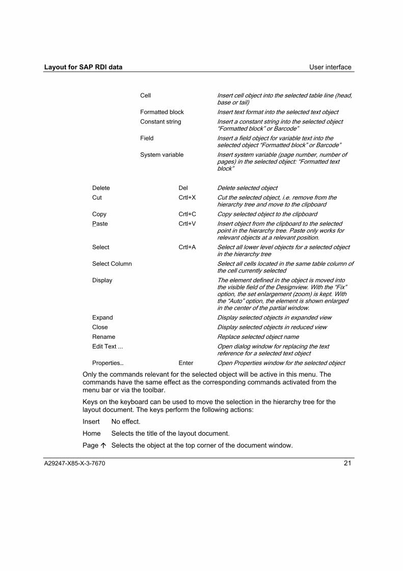
Right clicking on an object or a paste bar will open a menu with the following commands:Paste ? Page Type Insert page type object for the subdocument
assuming no page type has been defined. If apage type has already been defined, another pagetype can be inserted using a paste bar before orafter the existing page type.
Layer Insert a layer object at the selected point
Float area Insert a float area object at the selected point
Frame Insert frame object for the selected layer or cell
Loop Insert a loop object in the subdocument orselected frame
Text Insert a text in the marked subdocument, frame,cell or loop object
Table... Insert table object into the selected subdocument;the command opens a dialog to set up the table
Barcode Insert barcode object into the selected position
Image Insert image object into the selected position
Head Insert header into the selected table object; a tableobject may only contain one header
Row Insert a line in the selected table object
Tail Insert footer into the selected table object; a tableobject may only contain one footer
Layout for SAP RDI data User interface
A29247-X85-X-3-7670 21
Cell Insert cell object into the selected table line (head,base or tail)
Formatted block Insert text format into the selected text object
Constant string Insert a constant string into the selected object�Formatted block� or Barcode�
Field Insert a field object for variable text into theselected object �Formatted block� or Barcode�
System variable Insert system variable (page number, number ofpages) in the selected object: �Formatted textblock�
Delete Del Delete selected object
Cut Crtl+X Cut the selected object, i.e. remove from thehierarchy tree and move to the clipboard
Copy Crtl+C Copy selected object to the clipboard
Paste Crtl+V Insert object from the clipboard to the selectedpoint in the hierarchy tree. Paste only works forrelevant objects at a relevant position.
Select Crtl+A Select all lower level objects for a selected objectin the hierarchy tree
Select Column Select all cells located in the same table column ofthe cell currently selected
Display The element defined in the object is moved intothe visible field of the Designview. With the �Fix�option, the set enlargement (zoom) is kept. Withthe �Auto� option, the element is shown enlargedin the center of the partial window.
Expand Display selected objects in expanded view
Close Display selected objects in reduced view
Rename Replace selected object name
Edit Text ... Open dialog window for replacing the textreference for a selected text object
Properties� Enter Open Properties window for the selected object
Only the commands relevant for the selected object will be active in this menu. Thecommands have the same effect as the corresponding commands activated from themenu bar or via the toolbar.
Keys on the keyboard can be used to move the selection in the hierarchy tree for thelayout document. The keys perform the following actions:
Insert No effect.
Home Selects the title of the layout document.
Page " Selects the object at the top corner of the document window.

User interface Layout for SAP RDI data
22 A29247-X85-X-3-7670
Del Deletes selected objects and elements.
End Selects the object at the lower corner of the tree.
Page # Selects the object at the lower corner of the document window.
" Moves the selection from bottom to top. Starting from a selected object, the uparrow key inserts a paste bar and selects the object above it. You can now insertan element for the selected object at the position of the paste bar. Starting fromthe paste bar, the up arrow key selects the object above it.
$ Moves the selection starting from an object to the higher-level object. Startingfrom a selected object with lower level objects, the down arrow key reduces thedisplay to the selected object.
# Moves the selection from top to bottom. Starting from a selected object, thedown arrow key inserts a paste bar and selects the object above it. A new objectcan now be assigned to the selected object at the position of the paste bar.Starting from the paste bar, the down arrow key selects the object underneath it.
% Starting from an object, selects the object underneath it. Starting from a reducedview of an object, the right arrow key expands the display of the object; allassociated objects are displayed.
To select multiple consecutive objects in the hierarchy tree, select a symbol, then asecond symbol whilst holding down the Shift key &. All objects located between the twoobjects will now be selected.
To select several objects separately, press the Crtl key and click on the desired symbolsin succession in the hierarchy tree.
All objects are inserted into the hierarchy tree with a default name. The objects can berenamed in any way according to your own criteria. To rename an object, select therelevant name and right-click to open the selection menu where you can activate the writefunction in the name field using the �Rename� command. The write function can also beactivated by left clicking on the selected name field.
To edit the properties of an object, select the relevant symbol and open the Propertiesdialog.
In the Designview, the layout defined in the hierarchy tree is visualized. The Designviewis only for showing the design that can be processed only by defining objects and theirproperties in the tree structure.
In the Designview, a page (page type) is shown with elements for printing, which aredefined in corresponding objects in the hierarchy tree. To show images in the Designview,they must also be available in the current application directory as an emf file.
When you select objects in the hierarchy tree, the corresponding elements are selected inthe Designview.

Layout for SAP RDI data User interface
A29247-X85-X-3-7670 23
You can influence the display of the layout in the Designview by the checking the boxes inthe Designview selection bar.
Fig. 7: Designview selection bar
In the first selection bar box (from the left), you can select if you want to display just thevalid elements (i.e., the elements that will be viewed in the print image), or if elementsshould be visible that are defined for the draft layout but are not to be seen in the printedimage such as a float area. (In the current program version, this distinction does not yetexist).
If you have added sample data to the design data references, you can select in thesecond box if the reference names or sample data will be displayed in the Designview.
If you have created several page types, you can select in the third box the page type to bedisplayed in the window.
In the fourth box, select the size of the layout in the window. You can enlarge the normaldisplay of 100% in steps to 150%, 200% and 500%, and you can shrink the display insteps to 75%, 50%, 25% and 10%. You can also enlarge the display to the entire width ofthe Designview in the maximized layout program window, or reduce it so that then entirepage can be seen in the window.
In the �Auto� and �Fix� option fields, you can set if the selected elements to be displayedare to be automatically enlarged in the center of the partial window for the Designview(�Auto�), or if the set enlargement is to be kept (�Fix�). You display an element by the call�Display� from the object context menu that you open by clicking the right mouse key on aselected object in the hierarchy tree.
Fig. 8: Blanking individual layers in the Designview
In the boxes for blanking, you can blank the view of individual layers or float areas. Theeye symbol in front of a name means that the corresponding layer or float area is visible inthe design. An eye with a line through it means that the corresponding layer or float areais invisible in the design. By clicking the corresponding name, you can hide or show thedisplay.

User interface Layout for SAP RDI data
24 A29247-X85-X-3-7670
1.3.3 The Properties dialog
The properties of the objects in a layout document specify the details of the layout.
The object properties can be specified as default settings; all objects newly entered intothe layout description are stored using these default properties. The properties of theobjects defined in the layout can be edited in the Properties dialog. Default settings andthe properties dialog are manipulated in the Properties dialog.
Fig. 9: Properties dialog; an example with the properties of the �Formatted block� object and �General� tab
To set the default settings, select the �Default Settings� option from the �Options� menuand click on the name of the object type to open the Properties dialog. Only the propertiesof the selected object type are displayed for editing on one or more tabs in the dialogwindow in this case.
To set individual properties for the objects defined in the layout, open the Properties dialogusing one of the following options:• Double-click on an object,• Select object or objects and press the Enter key (↵),• Select object or objects and click the �Edit Properties� button in the object toolbar,• Select object or objects and select the �Properties�� option from the �Edit� menu,• Select object or objects and select the �Properties�� option from the selection menu
opened by right-clicking,

Layout for SAP RDI data User interface
A29247-X85-X-3-7670 25
If the Properties dialog window is opened for an individual object, all properties relating tothis object can be determined on one or more tabs in the dialog.
The general properties of an object can be modified in the printing process under specificconditions. The conditions and corresponding object properties are saved in columns inthe properties area of the dialog window. The first column always contains the standardproperties of the object. The other columns describe the conditions and correspondinglymodified properties. The scroll bar at the bottom edge of the property area only refers tothe condition columns. In the printing process, the conditions are processed according tothe sequence of the columns from left to right.
You can click the relevant buttons to open the dialog window �Condition text� to create anew condition, delete a selected condition, or change the sequence of the conditions.
Open the �Condition text �dialog window to create a new condition (only active whena condition can be created for the current object)
Delete selected condition (only active when a condition exists)
Shift the selected condition to the front (only active when there is another conditionin front of the selected condition)
Shift the selected condition to the rear (only active when there is another conditionbehind the selected condition)
If the Properties dialog window is opened for multiple objects of the same type, all theproperties for these objects can be edited together, assuming this is permissible forobjects of the same type. For example, the same character parameters and the same fontcan be set for several formatted blocks at the same time.

User interface Layout for SAP RDI data
26 A29247-X85-X-3-7670
Fig. 10: Properties dialog, opened for several objects of different types simultaneously
If the Properties dialog is opened for various objects, all the object properties aredisplayed but only those object properties that apply to all the selected objects can bereplaced.
Layout for SAP RDI data
A29247-X85-X-3-7670 27
2 Editing layouts for SAP RDI data
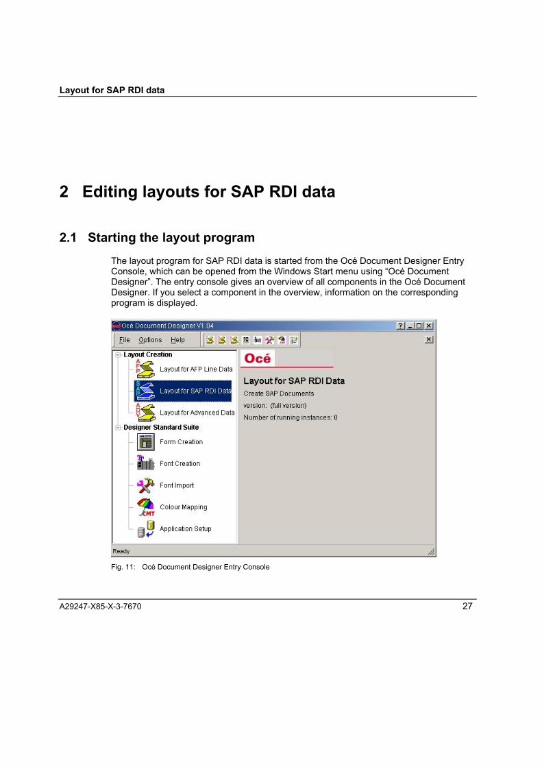
2.1 Starting the layout programThe layout program for SAP RDI data is started from the Océ Document Designer EntryConsole, which can be opened from the Windows Start menu using �Océ DocumentDesigner�. The entry console gives an overview of all components in the Océ DocumentDesigner. If you select a component in the overview, information on the correspondingprogram is displayed.
Fig. 11: Océ Document Designer Entry Console

Editing Layouts Layout for SAP RDI data
28 A29247-X85-X-3-7670
The layout program for SAP RDI data can be started from the entry console, by selecting�Layout for SAP RDI� and pressing the Enter key (↵), or double-clicking �Layout for SAPRDI� or clicking the �Layout for SAP RDI� button in the Entry Console toolbar.
From the Windows Start menu, the program �Layout for SAP RDI Data� can also bestarted directly under Programs/Océ Document Designer. To launch the program directly,you can also create a shortcut on your desktop.
2.2 Opening a layout documentAfter starting the program, you can
• Open an existing layout file or
• Create a new file for a layout document.
Fig. 12: �File� menu for starting the layout program
To open a file, go to the menu �File� and select the command �Open...�, or shortcut:Ctrl+O), or click the Open symbol in the symbol bar of the program window. This willopen the �Open� dialog box where you can select the required folder and the requiredlayout file with the file name extension .odd.
In the �File� menu, the names of the four last layout files edited are also displayed.Clicking on one of these filenames opens the corresponding file directly.
When a layout file is opened, a document window is opened in the program windowworkspace, where the objects of the layout are displayed hierarchically in a tree structure.
To create a new file, either select the �New� option from the �File� menu (shortcut: Crtl+N),or click the New button in the toolbar in the program window. This will open thedocument window with a basic standard layout in which a layout document is specifiedwith a subdocument and two empty page types.

Layout for SAP RDI data Editing Layouts
A29247-X85-X-3-7670 29
For the new layout file, the name Document# is given, # is the number of a newdocument within a session.
Fig. 13: Default setup for a new layout document.
2.3 Saving the current layout documentTo save a layout document in a layout file, either select the �Save� option from the �File�menu (shortcut: Crtl+S) or click the Save button in the toolbar in the program window.The save function is only active if changes have been made to the layout.
To save a layout document in a file with a different name or to save it in a different folder,select the �Save As�� command in the �File� menu. This will open the �Save As� dialogbox where you can select a different folder or create a new folder and enter a differentfilename.
A new layout document created can be saved in a layout file using �Save As��, even if nochanges have been made to the standard layout.

Editing Layouts Layout for SAP RDI data
A29247-X85-X-3-7670 30
2.4 Default settings for editing a layout
Fig. 14: Default settings for layout objects and elements
For editing a layout, default settings for properties of the layout objects and elements. Todo this, select the �Default properties ?� function from the �Options� menu. This opens asubmenu that you can use to define the properties as the defaults for every type of objectand element in the layout. If you add a new object to the layout, the default propertieshere are applied.
Clicking on the name of a type of object will open the corresponding Properties dialog boxby specifying the relevant properties on tabs.

Layout for SAP RDI data Editing Layouts
A29247-X85-X-3-7670 31
The following overview shows which default properties you can set for layout objects andelements:
SubdocumentGeneral
Type ..................................... Subdocument, Type name for the current object cannotbe replaced.
Output .................................. Checkbox, selected: The subdocument is also outputwhen the document is printed.Not selected: The subdocument is not output when thedocument is printed.
Name ...................................Name under which a new subdocument in the hierarchytree is created.
Comment .............................User note; the comment is not transferred to the printresources.
SubdocumentPage Order .......................... Box for selecting the page order when printing the
documentData Reference.................... SAPscript form Name of the SAPscript form for the data to
be printed in the document. Clicking the ... button opens adialog box where a SAPscript form can be selected fromthe list of all linked forms.
Default position for componentsPositioning type ................... Vertical float positionHorizontal reference point ... Reference point, leftHorizontal ............................ Box to select the unit:
�Millimeter�/�Centimeter�/�Inch�/�Point�Distance between the reference point in a horizontaldirection in the selected unit of measurement
Vertical clearance ................ Box to select the unit:�Millimeter�/�Centimeter�/�Inch�/�Point�Distance between the previously positioned element in avertical direction in the selected unit of measurement
Page TypeGeneral
Type ..................................... Page Type, Type name for the current object cannot bereplaced.
Output .................................. Checkbox, selected: The page type defined in the objectis also output when printing the document.Not selected: The page type defined in the object is notoutput when printing the document.

Editing Layouts Layout for SAP RDI data
32 A29247-X85-X-3-7670
Name ................................... Name under which a new page type in the hierarchy treeis created.
Comment ............................. User note; the comment is not transferred to the printresources.
Page TypePage Width .......................... Box to select the unit:
�Millimeter�/�Centimeter�/�Inch�/�Point�Page width in the selected unit of measurement
Page Height ......................... Box to select the unit:�Millimeter�/�Centimeter�/�Inch�/�Point�Page height in the selected unit of measurement
Page Type............................ Box to select the type of the current page:�First page�/�Next page�
Next page type..................... Box to select the type of the page following the currentpage: �First page�/�Next page�
Default position for componentsPositioning type.................... Fixed positionReference point ................... Reference point, top leftHorizontal ............................ Box to select the unit:
�Millimeter�/�Centimeter�/�Inch�/�Point�Distance between the reference point in a horizontaldirection in the selected unit of measurement
Vertical ................................. Box to select the unit:�Millimeter�/�Centimeter�/�Inch�/�Point�Distance between the reference point in a verticaldirection in the selected unit of measurement
Output definitionsOrientation ........................... �Portrait�/�Landscape� selection boxTwo-sided printing ............... Box for selecting two-sided printing:
�Single-sided�/ �Two-sided� / �Two-sided, mirrored onshort edge� / �Two-sided, 3rd and 4th print pages reversed�/ �Two-sided, mirrored on short edge, 3rd and 4th printpage reversed�
Pages per sheet................... Printing of multiple pages on the paper areaSelection box �1 page per sheet� / �2 pages per sheet�
Position of the print page ..... with single-sided printing: new sheetwith two-sided printing:: new sheet / next free partitioncurrent sheet / next free partition current front page / nextfree partition current rear page
Input tray reference.............. Selection box �Number� / �Identifier�With �Number� selected:Input tray number................. Number of the input trayWith �Identifier� selected:Input tray identifier ............... Designation of the input trayOutput tray number.............. Number of the output tray
Layout for SAP RDI data Editing Layouts
A29247-X85-X-3-7670 33
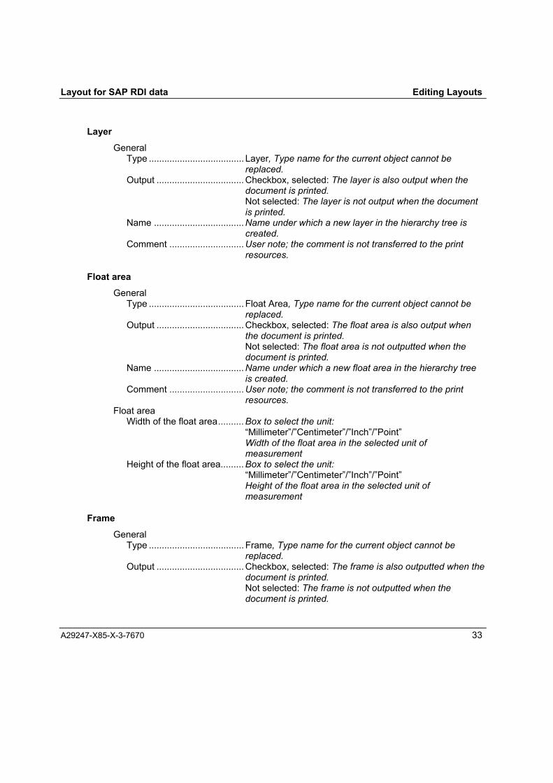
LayerGeneral
Type ..................................... Layer, Type name for the current object cannot bereplaced.
Output .................................. Checkbox, selected: The layer is also output when thedocument is printed.Not selected: The layer is not output when the documentis printed.
Name ...................................Name under which a new layer in the hierarchy tree iscreated.
Comment .............................User note; the comment is not transferred to the printresources.
Float areaGeneral
Type ..................................... Float Area, Type name for the current object cannot bereplaced.
Output .................................. Checkbox, selected: The float area is also output whenthe document is printed.Not selected: The float area is not outputted when thedocument is printed.
Name ...................................Name under which a new float area in the hierarchy treeis created.
Comment .............................User note; the comment is not transferred to the printresources.
Float areaWidth of the float area.......... Box to select the unit:
�Millimeter�/�Centimeter�/�Inch�/�Point�Width of the float area in the selected unit ofmeasurement
Height of the float area......... Box to select the unit:�Millimeter�/�Centimeter�/�Inch�/�Point�Height of the float area in the selected unit ofmeasurement
FrameGeneral
Type ..................................... Frame, Type name for the current object cannot bereplaced.
Output .................................. Checkbox, selected: The frame is also outputted when thedocument is printed.Not selected: The frame is not outputted when thedocument is printed.

Editing Layouts Layout for SAP RDI data
34 A29247-X85-X-3-7670
Name ................................... Name under which the �frame� object is created in thehierarchy tree.
Comment ............................. User note; the comment is not transferred to the printresources.
Default position for componentsPositioning type.................... Vertical float positionHorizontal reference point ... Reference point, leftHorizontal ............................ Box to select the unit:
�Millimeter�/�Centimeter�/�Inch�/�Point�Distance between the reference point in a horizontaldirection in the selected unit of measurement
Vertical clearance ................ Box to select the unit:�Millimeter�/�Centimeter�/�Inch�/�Point�Distance between the reference point in a verticaldirection in the selected unit of measurement
FrameWidth of the frame ............... Box to select the unit:
�Millimeter�/�Centimeter�/�Inch�/�Point�Width of the frame in the selected unit of measurement
Height of the frame .............. Box to select the unit:�Millimeter�/�Centimeter�/�Inch�/�Point�Height of the frame in the selected unit of measurement
LoopGeneral
Type ..................................... Loop, Type name for the current object cannot bereplaced.
Output .................................. Checkbox, selected: The loop is also output when thedocument is printed.Not selected: The loop is not output when the document isprinted.
Name ................................... Name under which the �Loop� object is created in thehierarchy tree.
Comment ............................. User note; the comment is not transferred to the printresources.
Default position for componentsPositioning type.................... Vertical float positionHorizontal reference point ... Reference point, leftHorizontal ............................ Box to select the unit:
�Millimeter�/�Centimeter�/�Inch�/�Point�Distance between the reference point in a horizontaldirection in the selected unit of measurement

Layout for SAP RDI data Editing Layouts
A29247-X85-X-3-7670 35
Vertical clearance ................ Box to select the unit:�Millimeter�/�Centimeter�/�Inch�/�Point�Distance between the reference point in a verticaldirection in the selected unit of measurement
LoopGroup ................................... Group name from the design data (taken from a SAPscript
form)Clicking the ... button opens a dialog box in which therepeated groups of the current design data are displayedfor selection.
TextGeneral
Type ..................................... Text, Type name for the current object cannot bereplaced.
Output .................................. Checkbox, selected: The text is also outputted when thedocument is printed.Not selected: The text is not outputted when thedocument is printed.
Name ...................................Name under which the �Text� object is created in thehierarchy tree.
Comment .............................User note; the comment is not transferred to the printresources.
TextPrint direction ....................... Box to select the print orientation: �Across� / �Up� / �Back�
/ �Down�
TableGeneral
Type ..................................... Table, Type name for the current object cannot bereplaced.
Output .................................. Checkbox, selected: The table is also output when thedocument is printed.Not selected: The table is not outputted when thedocument is printed.
Name ...................................Name under which the �Table� object is created in thehierarchy tree.
Comment .............................User note; the comment is not transferred to the printresources.
TableComposition ......................... Checkbox, selected: Composition in the table permitted
Not selected: Composition in the table not permittedMaximum width .................... Box to select the unit: �Millimeter� / �Centimeter� / �Inch� /
�Point�
Editing Layouts Layout for SAP RDI data
36 A29247-X85-X-3-7670
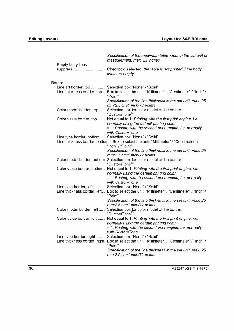
Specification of the maximum table width in the set unit ofmeasurement, max. 22 inches
Empty body linessuppress ............................. Checkbox, selected: the table is not printed if the body
lines are empty
BorderLine art border, top .............. Selection box �None� / �Solid�Line thickness border, top.... Box to select the unit: �Millimeter� / �Centimeter� / �Inch� /
�Point�Specification of the line thickness in the set unit, max. 25mm/2.5 cm/1 inch/72 points
Color model border, top ....... Selection box for color model of the border:�CustomTone®�
Color value border, top ........ Not equal to 1: Printing with the first print engine, i.e.normally using the default printing color.= 1: Printing with the second print engine, i.e. normallywith CustomTone.
Line type border, bottom...... Selection box �None� / �Solid�Line thickness border, bottom Box to select the unit: �Millimeter� / �Centimeter� /
�Inch� / �Point�Specification of the line thickness in the set unit, max. 25mm/2.5 cm/1 inch/72 points
Color model border, bottom. Selection box for color model of the border:�CustomTone®�
Color value border, bottom .. Not equal to 1: Printing with the first print engine, i.e.normally using the default printing color.= 1: Printing with the second print engine, i.e. normallywith CustomTone.
Line type border, left ............ Selection box �None� / �Solid�Line thickness border, left.... Box to select the unit: �Millimeter� / �Centimeter� / �Inch� /
�Point�Specification of the line thickness in the set unit, max. 25mm/2.5 cm/1 inch/72 points
Color model border, left ....... Selection box for color model of the border:�CustomTone®�
Color value border, left ........ Not equal to 1: Printing with the first print engine, i.e.normally using the default printing color.= 1: Printing with the second print engine, i.e. normallywith CustomTone.
Line type border, right.......... Selection box �None� / �Solid�Line thickness border, right.. Box to select the unit: �Millimeter� / �Centimeter� / �Inch� /
�Point�Specification of the line thickness in the set unit, max. 25mm/2.5 cm/1 inch/72 points

Layout for SAP RDI data Editing Layouts
A29247-X85-X-3-7670 37
Color model border, right ..... Selection box for color model of the border:�CustomTone®�
Color value border, right ...... Not equal to 1: Printing with the first print engine, i.e.normally using the default printing color.= 1: Printing with the second print engine, i.e. normallywith CustomTone.
ShadingFill style ................................ Box to select the fill style: �Color coverage�Color coverage..................... Specification of the color coverage in %Color model, foreground ...... Selection box for color model of the foreground:
�CustomTone®�Color value, foreground ....... Not equal to 1: Printing with the first print engine, i.e.
normally using the default printing color.= 1: Printing with the second print engine, i.e. normallywith CustomTone.
BarcodeGeneral
Type ..................................... Barcode, Type name for the current object cannot bereplaced.
Output .................................. Checkbox, selected: The barcode is also outputted whenthe document is printed.Not selected: The barcode is not outputted when thedocument is printed.
Name ...................................Name under which the �Barcode� object is created in thehierarchy tree.
Comment .............................User note; the comment is not transferred to the printresources.
BarcodePrint direction ....................... Box to select the print orientation: Across/Up/Back/DownType ..................................... Selection box for barcode typeModifier ................................ Selection box for modifier; Selection options depend on
the selected barcode typeModule width........................ Mils
Details of the module width in mm, min. 7, max. 254Module height ...................... Box to select the unit:
�Millimeter�/�Centimeter�/�Inch�/�Point�Width of the barcode in the selected unit of measurement,min.
HRI....................................... �Human Readable Interface� selection box:None/standard
Image

Editing Layouts Layout for SAP RDI data
38 A29247-X85-X-3-7670
GeneralType ..................................... Layer, Type name for the current object cannot be
replaced.Output .................................. Checkbox, selected: The image is also outputted when
the document is printed.Not selected: The image is not outputted when thedocument is printed.
Name ................................... Name under which the �Image� object is created in thehierarchy tree.
Comment ............................. User note; the comment is not transferred to the printresources.
ImagePrint direction ....................... Box for selecting �Across� / �Up� / �Back� / �Down�Type ..................................... Form (only the type of form is possible in the current
version)Name ................................... Name of the form (file name without a suffix)
Clicking on the button � opens a selection box in whichyou can select a suitable form from the current applicationdirectory or a subdirectory.
Storage site.......................... Path to the subdirectory within the application directory inwhich the image is saved
HeadGeneral
Type ..................................... Head, Type name for the current object cannot bereplaced.
Output .................................. Checkbox, selected: The head is also outputted when thedocument is printed.Not selected: The head is not outputted when thedocument is printed.
Name ................................... Name under which the �Head� object is created in thehierarchy tree.
Comment ............................. User note; the comment is not transferred to the printresources.
RowFixed height ......................... Checkbox, selectedRow height ........................... Box to select the unit:
�Millimeter�/�Centimeter�/�Inch�/�Point�Specification for the row height in the selected unit ofmeasurement
Border ....................................... as for table
Shading ..................................... as for table

Layout for SAP RDI data Editing Layouts
A29247-X85-X-3-7670 39
RowGeneral
Type ..................................... Row, Type name for the current object cannot bereplaced.
Output .................................. Checkbox, selected: The row is also outputted when thedocument is printed.Not selected: The row is not outputted when thedocument is printed.
Name ...................................Name under which the �Line� object is created in thehierarchy tree.
Comment .............................User note; the comment is not transferred to the printresources.
RowFixed height ......................... Checkbox, selectedRow height ........................... Box to select the unit:
�Millimeter�/�Centimeter�/�Inch�/�Point�Specification for the row height in the selected unit ofmeasurement
Group reference................... Group name from the current SAPscript formRelative reference................ Checkbox, selectedContext................................. Display: Name of the current SAPscript form
Border ....................................... as for table
Shading .....................................as for table
TailGeneral
Type ..................................... Tail, Type name for the current object cannot be replaced.Output .................................. Checkbox, selected: The tail is also output when the
document is printed.Not selected: The tail is not output when the document isprinted.
Name ...................................Name under which the �Tail� object is created in thehierarchy tree.
Comment .............................User note; the comment is not transferred to the printresources.
RowFixed height ......................... Checkbox, selectedRow height ........................... Box to select the unit:
�Millimeter�/�Centimeter�/�Inch�/�Point�Specification for the row height in the selected unit ofmeasurement

Editing Layouts Layout for SAP RDI data
40 A29247-X85-X-3-7670
Border ....................................... as for table
Shading ..................................... as for table
CellGeneral
Type ..................................... Cell, Type name for the current object cannot be replaced.Output .................................. Checkbox, selected: The cell is also output when the
document is printed.Not selected: The cell is not output when the document isprinted.
Name ................................... Name under which the �Cell� object is created in thehierarchy tree.
Comment ............................. User note; the comment is not transferred to the printresources.
CellCell width ............................. Box to select the unit: �Millimeter� / �Centimeter� / �Inch� /
�Point�Specification of the cell width in the set unit: Themaximum table width minus the sum of the remaining cellwidths of this line
Border ....................................... as for table
Shading ..................................... as for table
Default position for componentsPositioning type.................... Fixed positionReference point ................... Reference point, top leftHorizontal ............................ Box to select the unit:
�Millimeter�/�Centimeter�/�Inch�/�Point�Distance between the reference point in a horizontaldirection in the selected unit of measurement
Vertical ................................. Box to select the unit:�Millimeter�/�Centimeter�/�Inch�/�Point�Distance between the reference point in a verticaldirection in the selected unit of measurement
Formatted blockGeneral
Type ..................................... Formatted block, Type name for the current object cannotbe replaced.

Layout for SAP RDI data Editing Layouts
A29247-X85-X-3-7670 41
Output .................................. Checkbox, selected: The formatted block is also outputwhen the document is printed.Not selected: The formatted block is not output when thedocument is printed.
Name ...................................Name under which the �Formatted block� object is createdin the hierarchy tree.
Comment .............................User note; the comment is not transferred to the printresources.
CharactersCharacter size...................... Character size, at least 0.1, maximum 4.0Superscript/Subscript........... Box to select the unit: �Millimeter� / �Centimeter� / �Inch� /
�Point�Specification of the superscript or subscript setting in theset unit of measurement; negative number meanssubscript; max. 22 inches
Character rotation ................ Selection box for the character rotation:�0 degrees�/ �90 degrees� / �180 degrees� / �270 degrees�
Color model, foreground ...... Selection box for color model of the foreground:�CustomTone®�
Color value, foreground ....... Not equal to 1: Printing with the first print engine, i.e.normally using the default printing color.= 1: Printing with the second print engine, i.e. normallywith CustomTone.
FontFont type ..............................Name of fontFont size .............................. Box to select the unit:
�Millimeter�/�Centimeter�/�Inch�/�Point�Font size in the selected unit of measurementmin. 2 points, max. 1584 points
Font style .............................Selection box for font style �Normal� / �Bold� / �Italics� /�Bold Italics�
Constant stringGeneral
Type ..................................... Constant string, Type name for the current object cannotbe replaced.
Output .................................. Checkbox, selected: The constant string is also outputwhen the document is printed.Not selected: The constant string is not output when thedocument is printed.
Name ...................................Name under which the �Constant string� object is createdin the hierarchy tree.
Comment .............................User note; not transferred to the print resources.Constant string
Contents...............................Text entered like here in the document is printed.

Editing Layouts Layout for SAP RDI data
42 A29247-X85-X-3-7670
FieldGeneral
Type ..................................... Field, Type name for the current object cannot bereplaced.
Output .................................. Checkbox, selected: The field is also output when thedocument is printed.Not selected: The field is not output when the document isprinted.
Name ................................... Name under which the �Field� object is created in thehierarchy tree.
Comment ............................. User note; not transferred to the print resources.Design data field
Field reference..................... Field name from the design data (taken from a SAPscriptform)Clicking the ... button opens a dialog box in which the fieldreferences of the current design data are displayed forselection.
Context................................. Display: Name of the current SAPscript formData Type ............................ Box to select the data type: �Text�Following spaces ................. Checkbox, selected: A space is printed after the data.Preceding space .................. Checkbox, selected: A space is printed in front of the
data.Cut partial string................... Checkbox, selected: The partial string to be cut can be
defined by the initial position within the field and thelength
Initial position of the partial string Position in the field of the first character of thepartial string to be cut. Default: 1 (only exists when �Cutpartial string� is selected)
Length of partial string ......... Number of characters to be cut. Default: 1 (only existswhen �Cut partial string� is selected)
System variableGeneral
Type ..................................... System variable, Type name for the current object cannotbe replaced.
Output .................................. Checkbox, selected: The system variable is also outputwhen the document is printed.Not selected: The system variable is not output when thedocument is printed.
Name ................................... Name under which a new system variable in the hierarchytree is created.
Comment ............................. User note; not transferred to the print resources.System variable
System variable type ........... Selection box: �Page number�/�Number of pages�

Layout for SAP RDI data Editing Layouts
A29247-X85-X-3-7670 43
Fill string............................... Selection box:�None� / �Blank Space�/�*�/�.� / >#« / »-« / »0«
Number of positions ............. When selecting a fill string: Number of positions forsystem variables and the fill string
2.5 Transferring the description of the data structureTo create a document layout for SAP RDI data, the structure of the data to be printedmust be known to the layout program. In SAP applications the structure of the generateddata is described in a SAPscript form, which is used to control the print output within theSAP system. From this SAPscript form file, the Océ layout program for SAP-RDI data canextract the data structure description required to create the layout.
To transfer the data structure description to the current layout application, the relevantSAPscript form needs to be exported from the SAP system into a file which is madeavailable to the layout program. The layout program for SAP RDI data takes all theinformation describing the data structure from the SAPscript form file; the information onprinter control on the SAP system is not affected.
How to export an applications-specific SAPscript form file from the SAP system isdescribed in Appendix II.
To transfer the data structure description from the SAPscript form, select the�Connection�� command from the �Data� menu; this opens the �Data Connection� dialogbox. If there is no data structure description in the layout document, the �Data Connection�dialog box is empty. Clicking on the �Import...� button opens the �Imported SAPscriptForm� dialog box, which you can use to select and open a folder and a suitable file. Thereare no established conventions for the names of SAPscripts. When a file is opened, it ischecked to see if it contains a correct SAPscript form.
The layout program for the SAP RDI data saves the extracted data structure descriptionas design data in the current layout application.
Editing Layouts Layout for SAP RDI data
44 A29247-X85-X-3-7670
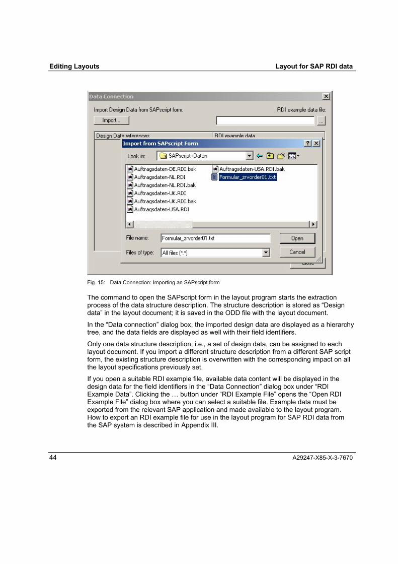
Fig. 15: Data Connection: Importing an SAPscript form
The command to open the SAPscript form in the layout program starts the extractionprocess of the data structure description. The structure description is stored as �Designdata� in the layout document; it is saved in the ODD file with the layout document.
In the �Data connection� dialog box, the imported design data are displayed as a hierarchytree, and the data fields are displayed as well with their field identifiers.
Only one data structure description, i.e., a set of design data, can be assigned to eachlayout document. If you import a different structure description from a different SAP scriptform, the existing structure description is overwritten with the corresponding impact on allthe layout specifications previously set.
If you open a suitable RDI example file, available data content will be displayed in thedesign data for the field identifiers in the �Data Connection� dialog box under �RDIExample Data�. Clicking the � button under �RDI Example File� opens the �Open RDIExample File� dialog box where you can select a suitable file. Example data must beexported from the relevant SAP application and made available to the layout program.How to export an RDI example file for use in the layout program for SAP RDI data fromthe SAP system is described in Appendix III.
Layout for SAP RDI data Editing Layouts
A29247-X85-X-3-7670 45
The example data is not transferred to the layout document; the selected example data isonly available during the current program session.
If an RDI file contains several documents (a new document is defined by �XX� in column10-11 of a data record), only the RDI example data of the last document are displayed inthe RDI file.
Only the RDI example data from the first instance (a new instance is defined by �X� incolumn 1-11 of a data record) of repeated groups are displayed from a document.
2.6 Defining layout objects in the hierarchy treeThe layout objects are defined in the hierarchy tree, shown in the layout window in theprogram. Here you can insert and delete objects as well as set and change the propertiesof objects.
A new layout document is created with a basic hierarchy tree with a subdocument objectand two page type objects.
To insert a new object:
⇒ Select the object in the hierarchy tree to which you want to assign the new object, and
⇒ Click the relevant icon in the object toolbar or select the relevant command from the�Insert� menu.
If you want to insert a new object at a very specific point in the hierarchy tree, use themouse pointer and the left mouse button to insert the paste bar. When the paste bar isset, you also select the object above it on the next highest hierarchy level to which thenew object to be inserted at the position of the paste bar is assigned.
To insert a new page type object into a hierarchy tree in which text or table objects arealready defined, the position of the object must be set to immediately underneath thesubdocument or the existing page type using the paste bar.

Editing Layouts Layout for SAP RDI data
46 A29247-X85-X-3-7670
Fig. 16: Paste bar in the hierarchy tree. In the example shown, a loop object, text object or a table object can beassigned to the �Subdocument� object at the position of the paste bar.
New objects are inserted with the default properties set.
To change the properties of an object, select the relevant icon in the hierarchy tree andopen the Properties dialog box using the Enter key (↵), using the �Properties�� commandfrom the �Edit� menu, using the �Properties...� command from the selection menu openedby right-clicking or by clicking the Properties button in the object toolbar.
In the property dialog window, you can assign specific properties to the objects in differenttabs. Implausible property data (such as width and height of a float area = 0 mm) appearred in the dialog window.
All objects that you save in the hierarchy tree and assign properties to are formatted in thebackground to be displayed in the Designview. Inconsistencies, violations of rules anderrors are recognized, and corresponding messages and detailed instructions are listed ina log file. The status bar of the program window notifies you that errors have beenidentified. Selecting �Display Errors� from the �View� menu, opens a window that showsthe contents of the log file.

Layout for SAP RDI data Editing Layouts
A29247-X85-X-3-7670 47
2.6.1 General object properties
Each object in a layout document has the properties �Type�, �Outputs�, �Name� and�Comment� assigned to it. These general object properties specify how the object isdisplayed in the layout document.
General object properties:
Type ..................................... Subdocument, Type name for the current object cannotbe replaced.
Output .................................. Checkbox, selected: The subdocument is also outputwhen the document is printed.Not selected: The subdocument is not output when thedocument is printed.
Name ...................................Name under which a new subdocument in the hierarchytree is created.
Comment .............................User note; the comment is not transferred to the printresources.
Under �General Object Properties�, you can define conditions to determine if, together withthe selection in the �Output� checkbox, the data defined or referenced in the object are tobe printed. Conditions can be defined in all objects except for the objects �Subdocument�and �Page type�.
To define a condition, click the button �Add condition� to open the dialog window�Condition text�.
Fig. 17: �Condition text� dialog box
In this dialog window, you can enter the data reference. You can enter a comparisonoperator and comparison value for the data as the condition to be fulfilled.
The data reference is selected from the design data that you have transferred from aSAPscript form. By clicking the button �Data reference�, you open the selection window

Editing Layouts Layout for SAP RDI data
48 A29247-X85-X-3-7670
�Design data reference� from which you can select the desired reference. Select thedesired reference row and close the selection window by clicking �OK�.
When selecting a reference entry, it is helpful to see example data that correspond to thedata. Clicking the selection button for the �RDI Example File� �...� opens the selection box�Open RDI Example File� where you can select and open a suitable file. When theexample file is opened, example data are shown in the selection window for the datareferences.
Fig. 18: �Design data references� dialog window with example data
After selecting the data reference, enter the comparison operator and comparison value.The following comparison operators can be entered:
Comparison operator: Meaning:
< Less than
<= Less than or equal to
== Equal to
>= Greater than or equal to
> Greater than
!= Not equal to

Layout for SAP RDI data Editing Layouts
A29247-X85-X-3-7670 49
You can enter a number or character sequence as the comparison value. Charactersequences are to be in quotation marks (example: "GBR�). The condition FIELD==�� isfulfilled when the corresponding field is empty in the print data.
Numbers are indicated without quotation marks. If there is no number under the referencewhen numbers are compared in the printing process, the comparison is evaluated as �Notfulfilled�.
Fig. 19: Example of a condition text
A condition can also be entered as several linked individual conditions by using thefollowing linking operators:
Linking operator: Meaning:
&& logical And
|| logical Or
The individual conditions are placed in parentheses. Linked conditions can be linked againby being grouped by additional parentheses.
Example: ((REF1==�ABC�)&&(REF2==123))||((REF1==�CDE�)&&(REF2==124))
The condition data are checked to see if they are formally correct, and faulty data appearred in the condition field. An attempt to transfer the properties with faulty conditioninformation for the object is rejected with a corresponding note.
You can also indicate several conditions in an object. In the �General� object tab,conditions are created in adjacent columns. In the printing process, the conditions areprocessed according to the sequence of the columns from left to right. You can changethe sequence of the conditions by clicking the buttons �Move condition forward� and�Move condition backward� . A condition can be further deleted with the button �Deletecondition�.

Editing Layouts Layout for SAP RDI data
50 A29247-X85-X-3-7670
2.6.2 Subdocument
The following is defined in the �Subdocument� object:
• The order in which the page type are to be printedand
• The design data provided by the field references for the variable data of thesubdocument.
SubdocumentPage Order .......................... Box for selecting the page order when printing the
documentData Reference.................... Name of the design data containing the field references
for the data fields in the subdocument. The name of thedesign data must be transferred from the list of availabledesign data, which is opened by clicking the ... button.Only one design data record can be assigned to asubdocument.
The design data must be extracted from a SAPscript form first and imported into the layoutfile (see Section 2.5, Transfer description of the data structure). Several design datarecords can be extracted from several SAPscript files and imported into a layout file. Eachsubdocument can be assigned only one design data record, however3.
The name of the design data record is transferred as the name of the subdocument objectwhen the data reference is assigned. You can, however, change the object name later.
2.6.3 Page type
In the �Page Type� object, the format of a page (width, height) and the allocation of thepage to the print media (paper) are defined with the properties below in the format andpaper properties.
The �Page Type� object is always assigned to the �Subdocument� object.
Page TypePage Width .......................... Box to select the unit:
�Millimeter�/�Centimeter�/�Inch�/�Point�Page width in the selected unit of measurement
Page Height ......................... Box to select the unit:�Millimeter�/�Centimeter�/�Inch�/�Point�Page height in the selected unit of measurement
3 In the current program version, only one design data record can be imported into a layout file.

Layout for SAP RDI data Editing Layouts
A29247-X85-X-3-7670 51
Page Type............................Box to select the type of the current page:�First page�/�Next page�
Next page type.....................Box to select the type of the page following the currentpage: �First page�/�Next page�
Output definitionsOrientation ........................... �Portrait�/�Landscape� selection boxTwo-sided printing................Box for selecting two-sided printing:
�Single-sided�/ �Two-sided� / �Two-sided, mirrored onshort edge� / �Two-sided, 3rd and 4th print pages reversed�/ �Two-sided, mirrored on short edge, 3rd and 4th printpage reversed�
Pages per sheet...................Printing of multiple pages on the paper areaSelection box �1 page per sheet� / �2 pages per sheet�
Position of the print page ..... with single-sided printing: new sheetwith two-sided printing:: new sheet / next free partitioncurrent sheet / next free partition current front page / nextfree partition current rear page
Input tray reference.............. Selection box �Number� / �Identifier�With �Number� selected:Input tray number................. Number of the input trayWith �Identifier� selected:Input tray identifier ............... Designation of the input trayOutput tray number .............. Number of the output tray
By default, a new subdocument is created with two page type objects with no assignedobjects.
Fig. 20: Default template for a new layout document
The given page type can be renamed, deleted or additional page types can be inserted.4
The �Page Type� object can be assigned the objects �Layer� and �Float Area�. A page typecan be assigned any number of float areas and any number of layers.
4 In the current program version only two different page types can be defined per subdocument, i.e. only two�page type� objects.

Editing Layouts Layout for SAP RDI data
52 A29247-X85-X-3-7670
2.6.4 Layer
Any number of layers can be defined for each page type. These layers are printed on topof each other in the printing process.
Areas can be defined in a layer that can be assigned text, tables and loops like thesubdocument. Text can also be directly assigned to the layer. In the print image, they thenappear in the float area defined for the subdocument.
In addition to text and tables, barcodes and images can also be assigned to each layer.Images and barcodes can only be placed by a layer definition in the document layout.
The layer object can only be assigned the following general properties:
Type ..................................... Layer, Type name for the current object cannot bereplaced.
Output .................................. Checkbox, selected: The layer is also output when thedocument is printed.Not selected: The layer is not output when the documentis printed.
Name ................................... Name under which a new layer in the hierarchy tree iscreated.
Comment ............................. User note; the comment is not transferred to the printresources.
In the layer object, conditions can be defined that can decide in the printing process,whether the layer is to be printed or not. The �Output� checkbox can be individuallyselected for each condition.

Layout for SAP RDI data Editing Layouts
A29247-X85-X-3-7670 53
Fig. 21: Example of a condition definition in a layer object: The layer is only printed in the printing process whenthe sequence of characters GBR appears in the ADDRESS_COUNTRY field.
2.6.5 Float area
The �Float Area� object is always assigned to a �Page Type� object and describes the areaon the page reserved for float texts or tables from the variable SAP RDI data. Multiple floatareas can be defined on a page type. In the �Float Area� object, the size of the float areaand its position on the page are described using the following properties:
Float areaWidth of the float area.......... Box to select the unit:
�Millimeter�/�Centimeter�/�Inch�/�Point�Width of the float area in the selected unit ofmeasurement
Height of the float area......... Box to select the unit:�Millimeter�/�Centimeter�/�Inch�/�Point�Height of the float area in the selected unit ofmeasurement
PositionPositioning type....................Selection box: �Fixed position�Reference point.................... Reference point for the position of the float area on the
page, selection box: �Top left�Horizontal ............................. Box to select the unit:
�Millimeter�/�Centimeter�/�Inch�/�Point�

Editing Layouts Layout for SAP RDI data
54 A29247-X85-X-3-7670
Horizontal position from the reference point in theselected unit of measurement
Vertical ................................. Box to select the unit:�Millimeter�/�Centimeter�/�Inch�/�Point�Vertical position from the reference point in the selectedunit of measurement
2.6.6 Frame
In the �Frame� object, you define an area in a layer in which float text or tables can beplaced from the variable SAP RDI data. Variable data can only be assigned to a specificframe in a layer. A frame can only be assigned as much variable data for which there isspace in the frame. If more data is assigned than can be printed in the frame, acorresponding error message is stored when formatting the frame element to be displayedin the Designview.
In the �Frame� object, the size of the float area and its position on the layer are describedusing the following properties:
PositionPositioning type.................... Selection box: �Fixed position�Reference point.................... Reference point for the position of the frame on the page,
selection box: �Top left�Horizontal............................. Box to select the unit:
�Millimeter�/�Centimeter�/�Inch�/�Point�Horizontal position from the reference point in theselected unit of measurement
Vertical ................................. Box to select the unit:�Millimeter�/�Centimeter�/�Inch�/�Point�Vertical position from the reference point in the selectedunit of measurement
FrameWidth of the frame ............... Box to select the unit:
�Millimeter�/�Centimeter�/�Inch�/�Point�Width of the frame in the selected unit of measurement
Height of the frame .............. Box to select the unit:�Millimeter�/�Centimeter�/�Inch�/�Point�Height of the frame in the selected unit of measurement
2.6.7 Loop
The �Loop� object indicates that text, tables, or table cells in the printing process are to bedynamically created depending on the data supplied in groups. The setting for the loop isthe group reference from the data structure description in the design data. Dynamic dataformation can only occur during the printing process in areas that are defined to acceptfloating text.

Layout for SAP RDI data Editing Layouts
A29247-X85-X-3-7670 55
The following properties can be assigned to the loop object:
LoopGroup ................................... Group reference
The group name is selected from the saved design dataContext................................. Name of the SAPscript form from which the relevant
design data was taken (assigned in the �Subdocument�object) and (possibly) the name of the higher-level groupor groups
The group name from the design data is automatically transferred to the loop object as anobject name, and the object name can be changed later as desired.
2.6.8 Text
�Text� objects are either assigned to the subdocument, a layer, a frame, a cell in a row ofa table, or to a loop. Any number of �Text� objects can be linked to the higher level object.
In the �Text� object, the print direction of the text and its position is defined by the followingproperties:
TextPrint direction ....................... Box to select the print orientation: �Across� / �Up� / �Back�
/ �Down�Position
Positioning type....................under subdocument, loop, frame: »Vertical float position«under layer, cell:�Fixed position�
Horizontal reference point.... Selection field for the horizontal reference point of the textposition in the subdocument, loop and frame: �Reference point, left�
Reference point.................... Selection field for the reference point of the text position ina cell �Reference point, top left�/�Reference point, topright�
Horizontal .............................Box to select the unit:�Millimeter�/�Centimeter�/�Inch�/�Point�Horizontal position from the reference point in theselected unit of measurement
Vertical .................................Box to select the unit:�Millimeter�/�Centimeter�/�Inch�/�Point�Vertical position from the reference point in the selectedunit of measurement

Editing Layouts Layout for SAP RDI data
56 A29247-X85-X-3-7670
To specify the format for the text, �Formatted block� objects are assigned to the �Text�object. In this process any number of different text formats can be used for variable andfixed texts.
The example in the following diagram below shows a �Text� object specifying a text in thelayout with three different formats. Text fields 1 to 3 with the fixed texts 1 and 2 are printedin format 1, text fields 4 to 6 in format 2 and fixed text 3 in format 3.
Fig. 22: Text with different formats for different text fields and fixed texts
2.6.9 Formatted block
The �Formatted block� object is assigned to the �Text� object and describes the format ofan area of text within the text area defined with the �Text� object. The �Formatted block�object specifies the font format for fields of the variable text and for constant strings withthe following properties:
FontFont type .............................. Name of fontFont size .............................. Box to select the unit: �Millimeter� / �Centimeter� / �Inch� /
�Point�Font size in the set unit of measurementmin. 2 points, max. 1584 points
Font style ............................. Selection box for font style �Normal� / �Bold� / �Italics� /�Bold Italics�
CharactersCharacter size...................... Character size, at least 0.1, maximum 4.0Superscript/Subscript........... Box to select the unit: �Millimeter� / �Centimeter� / �Inch� /
�Point�Specification of the superscript or subscript setting in theset unit of measurement; negative number meanssubscript; max. 22 inches
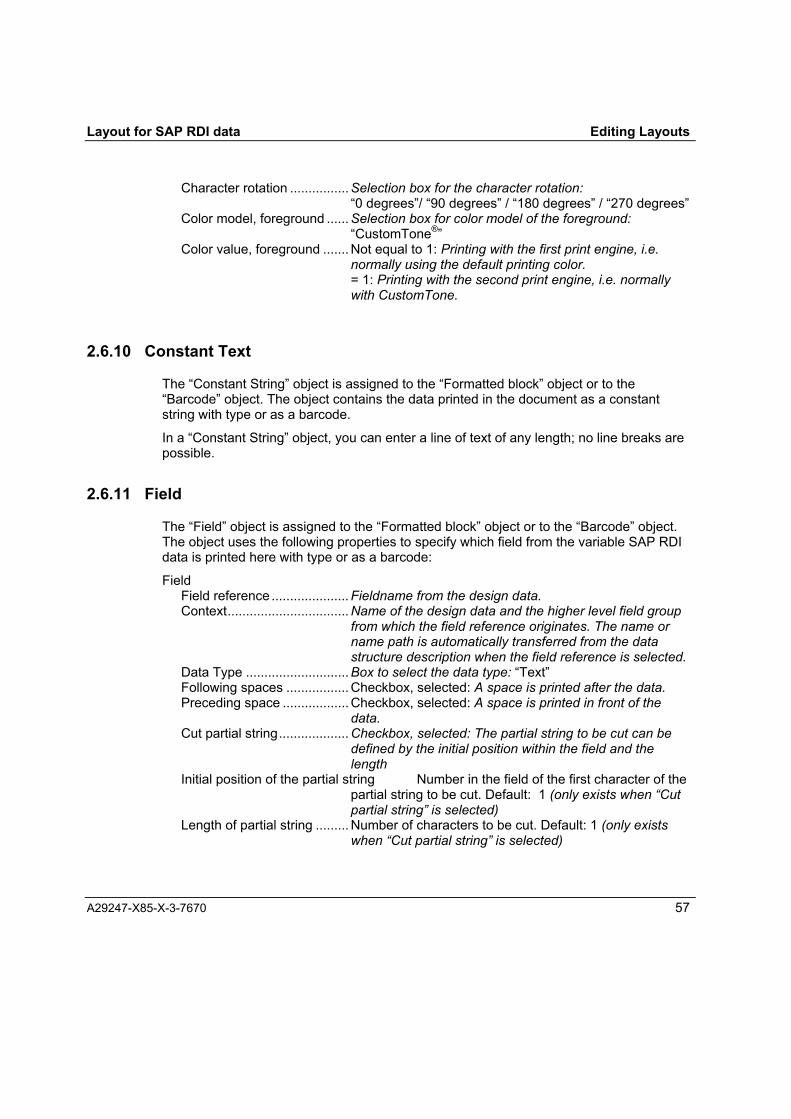
Layout for SAP RDI data Editing Layouts
A29247-X85-X-3-7670 57
Character rotation ................Selection box for the character rotation:�0 degrees�/ �90 degrees� / �180 degrees� / �270 degrees�
Color model, foreground ...... Selection box for color model of the foreground:�CustomTone®�
Color value, foreground ....... Not equal to 1: Printing with the first print engine, i.e.normally using the default printing color.= 1: Printing with the second print engine, i.e. normallywith CustomTone.
2.6.10 Constant Text
The �Constant String� object is assigned to the �Formatted block� object or to the�Barcode� object. The object contains the data printed in the document as a constantstring with type or as a barcode.
In a �Constant String� object, you can enter a line of text of any length; no line breaks arepossible.
2.6.11 Field
The �Field� object is assigned to the �Formatted block� object or to the �Barcode� object.The object uses the following properties to specify which field from the variable SAP RDIdata is printed here with type or as a barcode:
FieldField reference ..................... Fieldname from the design data.Context.................................Name of the design data and the higher level field group
from which the field reference originates. The name orname path is automatically transferred from the datastructure description when the field reference is selected.
Data Type ............................Box to select the data type: �Text�Following spaces ................. Checkbox, selected: A space is printed after the data.Preceding space .................. Checkbox, selected: A space is printed in front of the
data.Cut partial string................... Checkbox, selected: The partial string to be cut can be
defined by the initial position within the field and thelength
Initial position of the partial string Number in the field of the first character of thepartial string to be cut. Default: 1 (only exists when �Cutpartial string� is selected)
Length of partial string ......... Number of characters to be cut. Default: 1 (only existswhen �Cut partial string� is selected)

Editing Layouts Layout for SAP RDI data
58 A29247-X85-X-3-7670
The field reference name is transferred from the current design data to the field object.Clicking the ... button in the field reference row opens the selection box for the design datareference.
Fig. 23: Selection window for design data reference
The selected field reference name is transferred as the name of the object. Theautomatically entered object name can be changed as desired in the hierarchy tree.
Fields that can repeat in a data record with different data (float data) are to be assigned toloops corresponding to the element hierarchy in the design data. In the context, the namepath of names of the design data are entered via the names of the higher and lower-levelgroup upon the selection of a field reference. Only field references with a valid context aretransferred to the field object. The reference for a field in a field group can only be enteredwhen a loop object is defined in the hierarchy tree via the field for the group.

Layout for SAP RDI data Editing Layouts
A29247-X85-X-3-7670 59
Fig. 24: Selection of a field reference in a repeating group
In Fig. 24, a field reference is selected in the repeating group HEADER_DATA of thehigher-level group MAIN. This reference can only be assigned to a field object that is hungin the hierarchy tree as follows:
Barcodes can only be assigned fields that appear just once in a data record (fixed data).
In the �Design data reference� selection box, data from an RDI example file can bedisplayed. This means you can check whether the current design data that describe thedata structure match the data being printed; a plausible text must be assigned to thefieldname. To display example data, click the � button under �RDI Example File� to openthe �Open RDI Example File� dialog box where you can select a suitable file.
2.6.12 System Variables
The �System variable� object (that is assigned to a formatted text block like Constant Text)defines the output of the current page number in the document, or the number of pages ofthe current document being printed. Define the system variables with the followingproperties:
System variable

Editing Layouts Layout for SAP RDI data
60 A29247-X85-X-3-7670
System variable type ........... Selection box: �PAGE NUMBER�/�NUMBER OF PAGES�Fill string............................... Selection box:
�None� / �Space�/�*�/�.� / >#« / »-« / »0«Number of positions............. When selecting a fill string: Number of positions for the
system variableThe type description of the system variable �PAGE NUMBER� for the current pagenumber, or �NUMBER OF PAGES� for the number of pages in the current document istransferred in the selection also as a name for the current system variable object. Theautomatically used object name can then be changed as desired.
2.6.13 Table
The �Table� object assigned to the �Subdocument� object or a �Loop� object describes theposition of a table on the page and the external appearance of the table. The commandfor inserting a table, which can be accessed via the �Insert� menu or by clicking the Tablesbutton in the Object toolbar, opens the �Table� dialog box where you can make thesettings for the table to be inserted.
Fig. 25: �Table� dialog box

Layout for SAP RDI data Editing Layouts
A29247-X85-X-3-7670 61
As a general setting, you can indicate a maximum table width in millimeters, centimeters,inches or points, and you can indicate the number of cells to be created in a row. You canselect the creation of a head and tail in the checkbox; in addition, you can select if youwant permit the break for the next float area. These general settings can be changed asdesired later in the properties dialog for the created objects.
For the creation of the rows, you can select if you want to specify a static table with a fixednumber of rows for fixed data, or a dynamic table corresponding to selected groupreferences for float data.
If you select the �Static� option field, you can enter the number of rows to be created. Afterclicking �OK�, the definition appears in the hierarchy tree of a fixed table with objectscorresponding to the settings. For example, the following objects are created for a statictable specified with a head and tail, three cells and two rows:
Only fixed data can be printed in the cells of this table, i.e., the text objects of the cellobjects can only be assigned field objects with field references to fixed data and constanttext.
When you select the �Group-defined� option field, you can select data groups from thedesign data that are suitable for defining a �dynamic� table.
The groups defined in the design data are displayed in the selection box under �Group-defined�. Select a relevant group reference and enter it in the �Table group� field. Thegroup hierarchy in the design data can also be shown in the table hierarchy. By clicking��Insert child>>�, subordinate group references in the design data can be inserted assubordinate table elements in a higher-level group reference selected in the �Tablegroups� field.
Corresponding to the defined table hierarchy in the hierarchy tree, a dynamic table iscreated from the selected groups in which corresponding loop objects are specified for the

Editing Layouts Layout for SAP RDI data
62 A29247-X85-X-3-7670
float data. For example, the following objects are created for the selection that is shown inFig. 25:
The group references are entered as properties in the loop objects. Only float data can beprinted in the cells of this table, i.e., the text objects of the cell objects can only beassigned field objects with field references to float data of the relevant groups. Theattempt to assign another reference is rejected with the message: �The context of thedesign data reference is invalid�.The table created in the �Insert� dialog can be processed and changed as desired in thehierarchy tree.
The following properties are set in the table object:
ShadingFill style ................................ �Color coverage�Color coverage..................... Specification of the color coverage in %Color model, foreground ...... Selection box for color model of the foreground:
�CustomTone®�Color value, foreground ....... Not equal to 1: Printing with the first print engine, i.e.
normally using the default printing color.= 1: Printing with the second print engine, i.e. normallywith CustomTone.
BorderLine art border, top .............. Selection box �None� / �Solid�Line thickness border, top.... Box to select the unit: �Millimeter� / �Centimeter� / �Inch� /
�Point�Specification of the line thickness in the set unit, max. 25mm/2.5 cm/1 inch/72 points
Color model border, top ....... Selection box for color model of the border:�CustomTone®�

Layout for SAP RDI data Editing Layouts
A29247-X85-X-3-7670 63
Color value border, top ........ Not equal to 1: Printing with the first print engine, i.e.normally using the default printing color.= 1: Printing with the second print engine, i.e. normallywith CustomTone.
Line type border, bottom...... Selection box �None� / �Solid�Line thickness border, bottom Box to select the unit: �Millimeter� / �Centimeter� /
�Inch� / �Point�Specification of the line thickness in the set unit, max. 25mm/2.5 cm/1 inch/72 points
Color model border, bottom . Selection box for color model of the border:�CustomTone®�
Color value border, bottom .. Not equal to 1: Printing with the first print engine, i.e.normally using the default printing color.= 1: Printing with the second print engine, i.e. normallywith CustomTone.
Line type border, left ............ Selection box �None� / �Solid�Line thickness border, left .... Box to select the unit: �Millimeter� / �Centimeter� / �Inch� /
�Point�Specification of the line thickness in the set unit, max. 25mm/2.5 cm/1 inch/72 points
Color model border, left ....... Selection box for color model of the border:�CustomTone®�
Color value border, left......... Not equal to 1: Printing with the first print engine, i.e.normally using the default printing color.= 1: Printing with the second print engine, i.e. normallywith CustomTone.
Line type border, right .......... Selection box �None� / �Solid�Line thickness border, right.. Box to select the unit: �Millimeter� / �Centimeter� / �Inch� /
�Point�Specification of the line thickness in the set unit, max. 25mm/2.5 cm/1 inch/72 points
Color model border, right ..... Selection box for color model of the border:�CustomTone®�
Color value border, right ...... Not equal to 1: Printing with the first print engine, i.e.normally using the default printing color.= 1: Printing with the second print engine, i.e. normallywith CustomTone.
TableComposition ......................... Checkbox, selected: Break of the table to next float area
permittedNot selected: Break in the table not permitted
Maximum width .................... Box to select the unit: �Millimeter� / �Centimeter� / �Inch� /�Point�Specification of the maximum table width in the set unit of

Editing Layouts Layout for SAP RDI data
64 A29247-X85-X-3-7670
measurement, or the maximum width of the widest floatarea.
2.6.14 Row
The objects �Head�, �Row� and �Tail� are used to describe the external appearance of thetable rows. Only one head row and one tail row can be defined for a table.
The form of the head, the tail and the row in a table are described using the followingproperties:
RowFixed height ......................... Checkbox, selectedRow height ........................... Box to select the unit:
�Millimeter�/�Centimeter�/�Inch�/�Point�Specification for the row height in the selected unit ofmeasurement
Border ....................................... Properties as for tableShading ..................................... Properties as for table
2.6.15 Cell
The �cell� object describes the external appearance of a cell in a table row. The shading,border, and the width of the cell can be specified.
Cell:Cell width ............................. Box to select the unit: �Millimeter� / �Centimeter� / �Inch� /
�Point�Setting for the cell width in the unit of measurement set,as a maximum equal to the width of the table minus thetotal of all other cell widths in the row.
Border ....................................... as for tableShading ..................................... as for table
2.6.16 Barcode
The �Barcode� object describes the type and format along with the position of a barcode ina layer with the following properties:
PositionPositioning type.................... Selection box: �Fixed position�Reference point.................... Reference point for the position of the barcode on the
page, selection box: �Reference point, top left�

Layout for SAP RDI data Editing Layouts
A29247-X85-X-3-7670 65
Horizontal .............................Box to select the unit:�Millimeter�/�Centimeter�/�Inch�/�Point�Horizontal position from the reference point in theselected unit of measurement
Vertical .................................Box to select the unit:�Millimeter�/�Centimeter�/�Inch�/�Point�Vertical position from the reference point in the selectedunit of measurement
BarcodePrint direction ....................... Selection box: �Across� / �Up� / �Back� / �Down�Type .....................................Selection box for barcode types used: �Code 128�Modifier ................................Selection box of available modifiers: »0«Module width........................ Mils
Details of the module width in mm, min. 7, max. 254Module height ...................... Box to select the unit: �Millimeter� / �Centimeter� / �Inch� /
�Point�Specification of the module height in the set unit,min. 5 mm/0.102 cm/0.04 inch/2.9 pointmax. 1000 mm/10 cm/3.9 inch/280 point
HRI....................................... �Human Readable Interface� selection box: �None� /�Standard�
To define the data to be printed in the defined barcode, assign a �Constant String� or a�Field� object to the �Barcode� object. A barcode object can be assigned multiple�Constant string� and �Field� objects, including mixtures of the two types.
2.6.17 Image
The �Image� object determines which image (such as a form or logo) should be printed atwhich site in a layer by the following properties:
PositionPositioning type....................Selection box: �Fixed position�Reference point.................... Reference point for the position of the float area on the
page, selection box: �Reference point, top left�Horizontal .............................Box to select the unit:
�Millimeter�/�Centimeter�/�Inch�/�Point�Horizontal position from the reference point in theselected unit of measurement
Vertical .................................Box to select the unit:�Millimeter�/�Centimeter�/�Inch�/�Point�Vertical position from the reference point in the selectedunit of measurement
Image

Editing Layouts Layout for SAP RDI data
66 A29247-X85-X-3-7670
Print direction ....................... Box for selecting �Across� / �Up� / �Back� / �Down�Type ..................................... Form (only the type of form is possible in the current
version)Name ................................... Name of the form (file name without a suffix)
Clicking on the button � opens a selection box in whichyou can select a suitable form from the current applicationdirectory or a subdirectory.
Storage site.......................... Path to the subdirectory within the application directory inwhich the image is saved
In the current program version, only form images can be assigned. The image must beavailable in a file in the current application directory. To make the image visible in theDesignview, it must be available in the same subdirectory as an emf file in EMF format(Enhanced Metafile Format) with the same name as the form file.

Layout for SAP RDI data
A29247-X85-X-3-7670 67
3 Generating print resources for SAP RDI dataThe layout program for SAP RDI data uses the specifications on the document layout togenerate the print resources FormDef, the conversion information for the SAP RDI formatsand a list of all resources belonging to the application. The resources also include thecharacter sets specified in the layout for printing and the forms assigned to the pages.
The print resources can only be generated when all of the objects created in the layoutdefinition are correct and consistent. The consistency of the application can be checkedusing the validation function in the program. To do this, select the �Validate Application�command in the �File� menu. To transfer resources to PRISMAproduction, all the requiredresources must be available.
To start generating the resources, select the �Generate Print Resources�� commandfrom the �File� menu. The generation process can also be started using the keycombination Crtl+P.
To start the resource generation process, the �File Save As� dialog is opened where youcan specify a target folder and a filename for the resources. Only six characters can beentered for the name here because two characters are placed in front to identify thegenerated resources in the program and the filename can only be eight characters long.
Fig. 26: Generate Print Resources, �File Save As� dialog
�Save� is used to start the generation process, and a message with a report is displayed toindicate that this has been completed successfully.
Fig. 27: Message that resource generation is complete


Layout for SAP RDI data
A29247-X85-X-3-7670 69
4 Printing SAP RDI data
4.1 RequirementsIn order to be able to print SAP RDI data successfully via a PRISMAproduction system,the following components need to be installed and configured correctly.
Fig. 28: In Caldera Linux:PRISMAproduction V3.00.05 or V3.02 with RDI Formatter and the APA LanguageModule.
Fig. 29: In Sun Solaris:SAP R/3 V4.6
Fig. 30: In Sun Solaris and Caldera Linux:PRISMA Connect for SAP R/3 Software V1.00
Fig. 31: In Windows 2000:Océ Document Designer Standard Suite V1.00 and Océ Document Designer Layoutfor SAP-RDI-Data V1.00

Printing SAP RDI data Layout for SAP RDI data
70 A29247-X85-X-3-7670
4.2 Overview of the system structure
SAPscript
Production
Design
Printer
Layout information and resources
Document information
Fig. 32: Overview of the system structure

Layout for SAP RDI data Printing SAP RDI data
A29247-X85-X-3-7670 71
4.3 Installation and configuration
Installing/uninstalling RDI Formatter on PRISMAproductionThe RDI Formatter is supplied on CD as an add-on which can be installed inPRISMAproduction V3.00.05 or V3.02.
Installation
1. Log onto the Linux system as a �root� user.
2. Insert the CD into the drive and open a terminal window.
3. Mount the CD with: mount /mnt/cdrom.
4. Change to the directory: cd /mnt/cdrom/Installation/Linux.
5. From there, run the command ./install.rdiformatter �inst.
6. To install the licence, insert the licence diskette and in the PRISMAproduction Explorerselect �Configuration� -> �Licences�. �Import� is used to read the licence file from thediskette onto the system. Close the dialog with �Save�.
7. Unmount the CD with umount /mnt/cdrom.
Uninstallation
1. Log onto the Linux system as a �root� user.
2. Insert the CD into the drive and open a terminal window.
3. Mount the CD with: mount /mnt/cdrom.
4. Change to the directory: cd /mnt/cdrom/Installation/Linux.
5. From there, run the command ./install.rdiformatter �deinst.
6. To delete the licence, go to the PRISMAproduction Explorer and select: �Configuration�-> �Licences�. Select the licence and click �Delete�. The modified configuration mustthen be saved.
7. Unmount the CD with umount /mnt/cdrom.
Important: The RDI Formatter must be uninstalled before:� A new version of the formatter is installed.� A backup/restore/undo/update is run on PRISMAproduction.� PRISMAproduction is uninstalled.
Printing SAP RDI data Layout for SAP RDI data
72 A29247-X85-X-3-7670
Function: Error Messaging System
RDI Formatter
If an error occurs during formatting, you can decide how the RDI Formatter should react.
There are three types of behaviour:
• If a formatting error occurs, the whole formatting process will be terminated. Toachieve this, the attribute �OnErrorTerminate� in the parameter file �rdiformatter.ini�must have the value 0.
• If a formatting error occurs, the formatting process for document currently formattedwill be terminated. To achieve this, the attribute �OnErrorTerminate� in the parameterfile �rdiformatter.ini� must have the value 1.
• If a formatting error occurs, the formatting process for this component and for allsubordinate components will be terminated and will be continued with the nextcomponent. To achieve this, the attribute �OnErrorTerminate� in the parameter file�rdiformatter.ini� must have the value 2.
In addition to this three behaviours you can control by �ErrorReporting� in the parameterfile �rdiformatter.ini� whether the error messages are saved in a log file. To save themessages the value of the attribute must be 1 (=ON). If the value is 0 no error messageswill be saved.
Reasons for formatting errors are:
• The position of an object is outside of the dimensions of the page• The position of an object is outside of the dimensions of a superordinate component.
This might occur with the components �Float Area�, �Frame�, �Table� and �Cell�.• The dimensions exceed the allowed area of the superordinate component.• If a table should be wrapped and the wrapping property is set to �No�.• A barcode contains an invalid code point in the data to be displayed.• A condition could not be interpreted correctly.• A wrong context has been used when accessing the data.
If the logging of errors is activated, all errors of the last print job are stored in the fileLastJob.log in \\prismapro\diag\rdiformatter. Currently the last LastJob.log willbe overwritten with every new job.
Design ViewIf an errror occurs when formatting the DesignView, the wrong component and allsubordinate components are ignored. The process continues with the next component.View can request the error list from it�s GDA

Layout for SAP RDI data Printing SAP RDI data
A29247-X85-X-3-7670 73
4.4 WorkflowPRISMAproduction relates to the information for the job ticket to be generated from theheader page included in the machine type of the printer created in SAP. For this reason,identical entries need to be made in the configuration both on the PRISMA-side and onthe Solaris system and in SAP.
4.4.1 In PRISMAproduction and Sun Solaris
In PRISMAproduction the example file params.tpl (in u/prismapro/usapkit/res)needs to be copied to u/prismapro/usapkit/params in order to make individualsettings. If this file is not present, PRISMA Connect uses the default values.
The entries contained in the [Header page] section by default:Resource List Id = Resources =Job Class = Jobclass =
can be left as they are if they match the entries in the header page for the machine type inthe SAP system. If the entries there are different (e.g. no space between keyword andequals sign) they need to be modified here using an editor.
The procedure is the same in Sun Solaris. The example file params.tpl is located in thedirectory opt/usapkit.
Example file params.tpl:[Globals]# Server Host = <server hostname># FT Background = <Y or N># FT Timeout = <timeout in seconds># Delete Workfiles = <Y or N : Y will delete the docu anf jtic work files>
[Header page]# Job Ticket= <Keyword list separated by ;># Example: Job Ticket= job ticket =;Job Parameter:# Resource List Id = <Keyword list separated by ;># Form Name = <Keyword list separated by ;># Job Class = <Keyword list separated by ;>
[Devices]# <device namewith wildcards> = <hostname># Example: dint*er*= d241s090

Printing SAP RDI data Layout for SAP RDI data
74 A29247-X85-X-3-7670
4.4.2 Setting up machine types in SAP
The machine types for the PRISMA Connect Output Management System (OMS) need tobe defined on the SAP system. These machine types are assigned preparation typescontaining header pages from which PRISMAproduction writes information to the job ticketto obtain the correct resources for printing. In principle one machine type is created foreach SAP application. The machine type is then linked to a printer defined inPRISMAproduction.
The following description gives an example of how to set up a machine type and printer:
1. Log on to the SAP system as the spool administrator.

Layout for SAP RDI data Printing SAP RDI data
A29247-X85-X-3-7670 75
2. In the next window, press the �Full Administration� button to open the following view:
3. Open the �Device Types� tab and click the �Device Types� button. The list below will bedisplayed:

Printing SAP RDI data Layout for SAP RDI data
76 A29247-X85-X-3-7670
4. Select the ‘Plain’ machine type of which you want to create a copy under the name‘ZPLAIN’. Then click the ‘Change’ button:
5. In the ‘Device Type’ menu, click ‘Create Using Template’. The following window isdisplayed.
6. Enter the device type ‘ZPLAIN’ here. The remaining entries are transferred from the‘PLAIN’ template unchanged. Then save the device type.

Layout for SAP RDI data Printing SAP RDI data
A29247-X85-X-3-7670 77
7. After saving, you can assign a preparation type to the machine type and configure thepreparation type. To do this, click on the ‘Preparations’ button which is now displayed.The preparation type ‘X_Paper’ is displayed.
8. Double-clicking this entry will open a window with the assigned preparations:

Printing SAP RDI data Layout for SAP RDI data
78 A29247-X85-X-3-7670
9. Here, double-click the ‘Cover Page’ entry to activate the printing of cover pages(green icon). Click the cover page again. In the window below you can then modify thecover page parameters which have been read from PRISMAproduction:
10. The following parameters must be identical to those entered in the params file in SunSolaris and in PRISMAproduction:
Resources =Jobclass =
11. Then save your modifications. The ‘ZPLAIN’ device type can now be connected to aprinter set up as described below, in order to print the RDI data in PRISMAproduction.
4.4.3 Setting up printers in SAP
1. Log on to SAP spool management as described above.
2. Open the �Devices / Servers� tab and click the �Output Devices� button. The list belowwill be displayed:

Layout for SAP RDI data Printing SAP RDI data
A29247-X85-X-3-7670 79
3. In the �Output Device� menu, click the �Create� option. The dialog below is used toenter the specific features of the device:In the �Device Attributes� tab, you can first create an �Output Device� (5 figures) and a�Short Name� (max. 4 figures). The device type is then assigned to the printer. If RDIdata is to be printed via PRISMAproduction, it must be the ZPLAIN machine type. Asthe �Preparation Server�, enter the server on which the SAP application is running. Asthe �Machine Class�, select �Normal Printer�. �Model� and �Site� are fields where youcan enter any text you like:

Printing SAP RDI data Layout for SAP RDI data
80 A29247-X85-X-3-7670
4. The �Hostspool Access Method� tab is used to specify the access method for thespool. The access method �E� should be entered here for the External OutputManagement System. The �Host Printer is entered in the following format: Computername of the PRISMAproduction server: Printer name in PRISMAproduction. TheUniversal Sap Kit with Callback is set as the �Logical OMS�:
This completes the main steps in configuring the printer setup.

Layout for SAP RDI data
A29247-X85-X-3-7670 81
Appendix
I Simple example application for the �Layout for SAP RDI Data� program
II SAP RDI data structure, transferring the design data from the SAPscript form
III Exporting the SAPscript form and SAP RDI example from the SAP system
IV Functions in the �Layout for SAP RDI Data� programin Océ Document Designer V1.00

Annex I: Example application Layout for SAP RDI data
A29247-X85-X-3-7670 82
I Example applicationWhen installing the Océ Document Designer, some practical examples for the �Layout forSAP RDI Data� program are also saved on your PC that illustrate how to design andspecify a layout for data from SAP applications.
The example application �AuftragOH� demonstrates nearly all the possibilities of the layoutprogram. In the following, the steps to produce a layout corresponding to the practicalexample �AuftragOH� are explained. Follow the described steps and compare the resultswith �AuftragOH�. The design steps are only described for the different object types, notfor all objects of the example. By similarly applying the described steps for all objects inthe example, you can build the complete application AuftragOH.
Step 1: Create a new layout document
⇒ Create a new layout document using the �New� command from the �File� menu or byclicking the �New Document� button in the toolbar.
• Using the �New Document� command will open a standard document with onesubdocument and two page types.
• The suggested names �document template1�, �subdocument1�, �FirstPage� and�NextPage� can be changed to anything you like by clicking on a highlighted namefield.
Step 2: Setting up pagesIf all the pages in the print job are to be printed in the same layout, only one page typeneeds to be defined. In this case, one of the two specified page type objects must bedeleted. Bear in mind that in the properties of the only page type, �First Page� must be setboth for the page type and for the follow-on page.
If you would like to define different layouts for the first and following pages, set the type�First Page� in the properties of the first page, and the type �Next Page� for the following

Layout for SAP RDI data Annex I: Example application
A29247-X85-X-3-7670 83
page. In the properties of the second page, set �Next Page� as the page type and enterwhich page type is to be printed as further page (in the current program version, only thepage type "Next Page" can be specified).
In the example we want to give the first page a different layout to the next pages. So wedefine a �First Page� and a �Next Page�, and specify that after the first page a next page isprinted, and after a next page, another next page. This adheres to the standard structuredefined for the subdocument with two page types.
You can set the paper format for the print pages In the Properties dialog for the pagetypes. DIN A 4 Portrait (width 210 mm, height 297 mm) is the default, which we will stickto for our example.
Step 3: Importing design data from the SAPscript form and assigning it to thesubdocument:
⇒ Select the �Connection�� function from the �Data� menu. Activating this command willopen the �Data Connection� dialog which allows you to import the required data fromthe SAPscript form.
⇒ Click the �Import ... � button to open the file selection dialog �Import SAPscript Form�where you can select the form file from which you want to transfer the form data. Forour example, select the file Formular_zrvorder01.txt from the pathODD_Default_Base/AuftragOH/SAPscript+Daten.
⇒ Clicking on �Open� will open the SAPscript form file and transfer the data relevant forthe layout program into the current layout document.
Relevant data are extracted from the SAPscript form contained in the selected file andtransferred into the current application in the form of a data structure description as�design data" under the name of the SAPscript form. The data transferred from theSAPscript form are described in Appendix II.
In addition to the design data that contain only data references, you can also transferexample data that give you a realistic image of the layout in the Designview. You can thendisplay the layout in the Designview with data references or sample data.
⇒ To transfer sample data, open the selection window "Open RDI example File" byclicking the ... button under �RDI Example File:� in the dialog window �DataConnection�. In our example, select the file Auftragsdaten-DE.RDI via the pathODD_Default_Base/AuftragOH/SAPscript+Daten.
The sample data are not saved permanently in the layout document. It is only available inthe current session for a realistic representation of the layout design.
To assign data references to text blocks formatted in the layout design, assign the currentdesign data to the subdocument as follows:

Annex I: Example application Layout for SAP RDI data
84 A29247-X85-X-3-7670
⇒ Open the properties dialog for the subdocument and select the tab �Subdocument�.Open the selection window �Design Data Selection� with the selection button in theline �Data Reference�.
⇒ In the �Design Data Reference� selection window, select the design data transferredfrom the SAPscript form (in our example, ZRVORDER01), and transfer it to thesubdocument by clicking "OK".
When you leave the properties dialog for the subdocument, the name of the design data(originally the name of the SAPscript form) is applied as the name for the subdocument.You can change the automatically entered name of the subdocument as desired. In theexample �AuftragOH�, the subdocument object is called �subdocument1�.
There is no set sequence for defining the other layout elements in corresponding layoutobjects, apart from the hierarchical sequence, in which lower-level objects can only becreated when there is a higher-level object. Nevertheless, it is useful to maintain a certainsequence to avoid positioning conflicts. It is hence recommendable to first position the"fixed� elements of a print job, such as forms and fixed texts, to see where there is spacefor float text and dynamic tables.
Step 4: Establishing layersIn the AuftragOH example, each page type is assigned six layers that are conditionallyoutput in the printing process depending on the identified language and the localconventional address formatting in the variable data from the SAP application.
⇒ Select a page object in the hierarchy tree and add the layer, either by clicking thelayer symbol in the object toolbar, or by selecting �Layer� from the �Insert� menu. If afloat area is already defined for the page object, you must place a paste bar over thefloat area object to insert a layer object in the hierarchy tree.
⇒ Give each newly inserted layer an individual name
⇒ Define the condition under which the layer is to be printed:Click to create a new condition for the layer in the properties dialog. Select the datareference for the condition, and indicate the condition.
In the example AuftragOH, the layer �Lay1-De� is only to be printed if a 1 is in the printdata under the reference ZRVORDER01.ADDRESS_RECEIVER_L, or if the field isempty.

Layout for SAP RDI data Annex I: Example application
A29247-X85-X-3-7670 85
Fig. 33: Conditions for printing a layer
Step 5: Assigning formsTo provide orientation in the further layout design, assign to each layer the form that is tobe printed on the respective layer, and make the form visible in the Designview. You canalso assign several forms to a layer. The forms must be in files in a suitable format.
To make a form visible in the Designview of the layout program, the form must also beavailable in EMF format. The .emf file corresponding to the form must be saved with thesame file name in the same folder as the form file.
To assign a form and make it visible, proceed as follows:
⇒ Select the relevant layer object in the hierarchy tree and add an image object, eitherby clicking the image symbol in the object toolbar, or by selecting �Image� from the�Insert� menu.
• The image object is inserted with the standard name �image�. You can change thename as desired.
⇒ Select the newly inserted image object, and open the properties dialog. �Form� islisted as the image type in the �Image� tab. Only this type can be assigned in thecurrent program version.

Annex I: Example application Layout for SAP RDI data
86 A29247-X85-X-3-7670
⇒ Click the ... button in the line �Name� of the �Image� tab to open the selection window�Select Resource".
Fig. 34: Selecting a form
⇒ In our example, select the form o1auf1st from the folder Auftrag_OH. Because an.emf file for this form is available with the same name, the form is displayed in thepreview field of the selection window. Click �OK� to transfer the form name and filepath to your layout design, and close the selection window.

Layout for SAP RDI data Annex I: Example application
A29247-X85-X-3-7670 87
Fig. 35: Name and storage location of a form as properties of an image object
The form named 01AUF1ST that is stored both as a form and as a .wmf file in the folderAuftrag_OH of the current application directory is then assigned to your layout design.Keep the default printing direction �across� (up, back, down are also possible).
Also keep the defaults in the �Position� tab. The positioning type �Fixed Position� andreference point �Reference point top left� cannot be changed for a form. You can changethe position, but this would not make sense in our example since the form covers theentire page size. Position information outside the specified page is rejected with acorresponding error message.
The assigned form can now be seen in the Designview of the layout.
In the AuftragOH example, there are two forms for each page, a German and an Englishone. The forms are each assigned to their own layer that is conditionally selected andprinted in the printing process depending on the language of the variable data. In theDesignview, all layers and hence all forms are displayed superimposed. However, you canspecifically hide individual layers from the display (see Designview selection bar).

Annex I: Example application Layout for SAP RDI data
88 A29247-X85-X-3-7670
Step 6: Placing fixed texts on layersOn each layer, you can position fixed texts from constant default texts or fields of variabledata as either text or barcodes.
To place text on a layer in a fixed position, proceed as follows:
⇒ Select the relevant layer object (Lay1-D in the example AuftragOH), and insert a textobject either by clicking the text symbol in the object toolbar, or by selecting �Text�from the �Insert� menu. The text object is inserted with the name �text�, which you canchange as desired (in the example AuftragOH: �Order confirmation�).
⇒ Select the inserted text object and add a formatted text block, either by clicking thesymbol �Formatted Text Block� in the object toolbar, or by selecting �Formatted TextBlock� from the �Insert� menu. The object is inserted with the name �format�. In ourexample, the name was changed to �Nimb-12-fett".
⇒ Assign the desired properties to the text format in the properties dialog. In ourexample, the following properties are assigned to the text format:General:
Output: yesName: Nimb-12-fett
Characters:Character size: 1,5Superscript/Subscript: 0 millimetersCharacter rotation: 0 degreesColor model, foreground: CustomToneColor value, foreground: 0
Font:Font type: minbusromdFont size: 12 pointFont style: Bold
You can only assign a font that is available in the font library of the current application(set in the Application Setup).
⇒ Assign text content to the text format.You can either assign a constant text, a text field (reference to a text field in thevariable data), or a system variable (current page number or number of pages).Assign the text content to a corresponding insert command, either by clicking therelevant symbol, or by making the relevant selection from the �Insert� menu.In our example, the constant text �Order Confirmation� is assigned as content.

Layout for SAP RDI data Annex I: Example application
A29247-X85-X-3-7670 89
You can also edit text elements in the �Edit Text Elements� dialog window.
⇒ The dialog window opens for the selected text object by clicking the symbol �Edit Text�in the object toolbar, or by selecting �Edit Text...� from the �Edit menu�.
Fig. 36: Entering a constant text in the �Edit Text Element� dialog window.
⇒ To define a constant text, enter the desired text in the text field of the dialog window,assign the text to the object by clicking �Apply�, and leave the dialog window byclicking �OK�. For the current text object, this creates an object �Formatted Text Block�with default properties and an object �Constant Text� with the entered content.
⇒ To define a system variable, click the button �System Variable....� to open the window�Select System Variable�, in which you can select �Page Number� or "Number ofPages�.

Annex I: Example application Layout for SAP RDI data
90 A29247-X85-X-3-7670
⇒ To define a text field from the variable data, click the button �Data Reference...� toopen the selection window �Design Data Reference�, in which you can select a fieldreference for corresponding fixed data from the current design data.
• In the Designview, the position of the text is indicated as a blue square. Constant textis visible with its content, and field references are visible with the corresponding fieldname.
Step 7: Setting up float areas and framesTo print float text from the variable RDI data and for dynamic tables, corresponding areasmust be provided.
General float areas are assigned to the logical page. All data assigned to these float areasare printed out independent of defined layers. In the printing process, as soon as a floatarea is filled with text, the text continues in the next float area. The continuation sequenceof the float areas corresponds to the definition sequence in the hierarchy tree from top tobottom. Once all float areas on a page are printed, the next page is started.
If float data or dynamic tables are to be printed on specific layers, corresponding areasmust be defined in these layers. Areas for float text or dynamic tables can also be in tablecells. When designing the layout, make sure that frames are large enough for theanticipated data. Automatic breaks from one frame to another are not possible.
To define a float area for a page type, proceed as follows:
⇒ Select the page object in the hierarchy tree and add a float area object, either byclicking the float area symbol in the object toolbar, or by selecting �Float Area� fromthe �Insert� menu.
⇒ Set the size of the float area in the properties tab �Float Area� of the float area object.The float area cannot be bigger than the page that you have defined in the �PageType� object. Instructions that lead to a conflict appear red in the properties dialog.
⇒ Set the position of the float area on the logical page in the properties tab �Position� ofthe float area object. The float area is placed at a fixed position, and the referencepoint is always at the top left. The position must be selected so that the entire definedsize of the float area remains on the logical page (as defined in the page type object).Instructions that lead to a conflict appear red in the properties dialog.
• You can also superimpose float areas (areas of the same size in the same position)and selectively output them according to defined conditions.
• A defined float area is visible in the Designview with a blue border as long as thecorresponding object is selected in the hierarchy tree.
No additional objects are assigned to the float areas. All texts, repeat texts in loops andtables that you assign to the subdocument area are printed in the defined float areas.
In the example AuftragOH, a float area is defined for each page type, and the float areaon the next page is bigger than that on the first page. The repeating data of the delivery

Layout for SAP RDI data Annex I: Example application
A29247-X85-X-3-7670 91
and payment conditions and the items and sums defined in the tables from the variableRDI data are printed in these float areas.
To define a frame on a layer or in a cell, proceed as follows:
⇒ Select the relevant layer or cell object in the hierarchy tree and add a frame object,either by clicking the frame symbol in the object toolbar, or by selecting �Frame� fromthe �Insert� menu.
⇒ Set the position of the frame in the �Position� tab in the object properties. The positionof a frame is fixed in the layer or table cell; the reference point is the top left. Theposition must be located so that the entire frame lies on the layer or within the cell.Instructions that cause a conflict appear red in the properties dialog.
⇒ Set the size of the frame in the �Frame� tab in the object properties. The frame cannotbe larger than the layer (same size as the page) or the cell. The frame must alsocompletely fit inside the layer or cell after the assigned position. Instructions that leadto a conflict appear red in the properties dialog.
• A defined frame is visible in the Designview of the layer or cell with a blue border aslong as the corresponding object is selected in the hierarchy tree.
In the AuftragOH example, frames are defined on the defined address layers (such asLay1-Adresse-De) in which the address texts from the variable RDI data can be printed.
Step 8: Assigning float textTo assign float text to your layout, corresponding text references must be available in thedesign data. As described in step 3, import the design data from an SAPscript form, andassign it to the current subdocument.
Float text can be assigned to float areas or frames in layers or table cells. Float data canbe defined in the variable RDI data either as unique data within a data set, or as datarepeating in groups that are to be printed in data-dependent (dynamic) lists or tables.Unique data are assigned to float areas or frames as individual float text. Correspondingloops must be defined for repeating groups.
Prerequisites for assigning a float text are a text object in which it is determined where thetext is to be printed (text position), and a format object (formatted text block) in which thecharacter representation and font determine how the text is to be printed. For text for floatareas, the corresponding text object is assigned to the subdocument; for text for frames,to the frame object.
To assign a single float text, proceed as follows:
⇒ Select the relevant object �Formatted Text Block�, and insert a field object, either byclicking the field symbol (<...>) in the object toolbar, or by selecting �Field� from the�Insert� menu.

Annex I: Example application Layout for SAP RDI data
92 A29247-X85-X-3-7670
⇒ Assign a field reference to the field object. In the �Design Data Field� tab of the fieldproperties dialog, click the ... button in the "Field Reference� line to open the selectionwindow for the field references of the current design data. Only the field references fordata that appear just once per data set are now displayed.
⇒ Select the desired field reference, and apply it to the field object by clicking "OK". Thename of the field reference is applied as the name of the field object.
• You can now add a space in front of or after the text, or cut a partial string from thefield to print it.
As an example of a single field assignment, you will find the text field Adr-Zeile1 in thelayout �AuftragOH� on the first page in the layer �Lay1-Adresse-De� in the frame �Adresse-DE�, in which the formatted text block �Elite� is defined and assigned the field�ADDRESS_NAME1�.
To print repeating data from text groups in lists or tables, a loop must be defined to assignthe group. For repeating data that are to be printed in general float areas, the loopdefinition is assigned to the subdocument. For repeating data in frames, the loop definitionis assigned to the respective frame.

Layout for SAP RDI data Annex I: Example application
A29247-X85-X-3-7670 93
Fig. 37: Example of selecting a field reference from the design data
To create a loop object in the hierarchy tree:
⇒ Select the subdocument object or a frame object and insert the loop field object, eitherby clicking the loop symbol in the object toolbar, or by selecting �Loop� from the�Insert� menu.
⇒ Assign a group to the loop object. In the properties dialog, click the ... button on the�Loop� tab in the �Group� line to open the selection window �Design Data Reference�in which you can select the relevant group. Note that the group hierarchy must bereproduced in the loop hierarchy. Only a group from the highest level can be assignedto a loop object that is directly assigned to a frame or float area. For a subgroup, aloop must be assigned to a higher-level loop.

Annex I: Example application Layout for SAP RDI data
94 A29247-X85-X-3-7670
In the example AuftragOH, a list with the delivery and payment conditions is to be printedin the general float areas. The loop hierarchy is created correspondingly to the grouphierarchy of the repeating data in the hierarchy tree of the objects.
The data of the �Line� field repeat in the group �SD_RVADOR01�_TEXT_DEFAULT� thatrepeats in the group �HEADER_TEXT�. �HEADER_TEXT� is a repeating group from themain group �MAIN�.
• The initial position of a float area is visible in the Designview as a blue square as longas the corresponding object is selected in the hierarchy tree. Loop objects that asvirtual objects do not refer to specific elements of the layout are not seen in theDesignview.
Step 9: Setting up tablesTables can be formed as fixed tables from data that only occur once, or dynamically fromdata that repeat in groups. Corresponding loops must be defined in the tables forrepeating data.
Tables can be printed in the general float areas or in defined frames. Tables in generalfloat areas are assigned to the subdocument in the object hierarchy tree, tables in framesare assigned to the respective frame. Tables that are built entirely from a repeating groupmust be subordinated to a corresponding loop.
To set up a table, proceed as follows:
⇒ Select the object in the hierarchy tree to which you want to assign a table, and insert atable object. Open the dialog window �Table� by clicking the table symbol in the objecttoolbar, or by selecting �Table� from the �Insert� menu.
⇒ Enter the maximum width of the table, select the number of cells, select thecorresponding checkboxes to indicate whether headers and footers are added, andwhether the table is to be allowed to break and continue in the next flow area.

Layout for SAP RDI data Annex I: Example application
A29247-X85-X-3-7670 95
⇒ By selecting the corresponding option field, choose whether you want to create astatic or a group-defined table. In a static table, only data that only appear once ineach data set can be listed.
⇒ If you select �Group-Defined�, the relevant data groups of the current design data areoffered for selection under �Design Data Groups�. You can transfer the relevant groupreferences from the design data groups to table groups. Groups subordinate in thedesign data hierarchy can also be inserted subordinate in the table hierarchy as a�child�.
⇒ Click on �OK� to close the dialog window for the table definition. In the hierarchy treeof the objects, a hierarchical object structure is now created that corresponds to theselected table definitions.
• The created table is visible in the Designview with a blue border as long as thecorresponding object is selected in the hierarchy tree.
The created structures can be changed as desired with the available functions for editingthe objects in the hierarchy tree. Corresponding texts are always to be assigned to the cellobjects of the created table structure.
Step 10: Validating a designAs processing progresses, all information for defining a layout in the hierarchy tree ischecked as soon as possible to see if it is formally correct and consistent.
Information in the properties dialog for an object that can be identified as inconsistentimmediately upon being entered appears in red lettering in the dialog window and is notapplied as a property for the object.
If during formatting (newly inserted objects and changes to the object properties areformatted in the background after the corresponding entries are made) a problem isrecognized in relationship to earlier specifications, the note �Errors arose duringformatting� appears in the status bar of the program window. This occurs for examplewhen you shrink a frame in which a text has been placed in a fixed position, so that thetext position no longer lies in the frame. A description of the errors recognized duringformatting is shown in the display window �List of current errors� that you can open byselecting �Display errors� from the "View� menu.
Basic problems that affect the entire layout design can only be recognized if all theelements of the layout design are validated in context. If for example you have defined thetype �Next page� as the next page in the page object following the type �First page�, andyou later delete the object for the next page from the hierarchy tree, a problem isgenerated that can only be identified during overall validation.
To validate the layout design, call up the validation function by clicking on the validationsymbol in the document toolbar, or by selecting �Validate Application� from the �File"menu. If errors are recognized during validation, a corresponding error message appears.

Annex I: Example application Layout for SAP RDI data
96 A29247-X85-X-3-7670
If no error is recognized, the message �Validation was successful� appears uponconclusion of the validation.
Step 11: Generating printing resourcesIn the last step of the layout design, generate the printing resources from the design dataas follows:
⇒ Click on the symbol �Generate Print Resources� in the document toolbar, or call upthe generation procedure for the print resources from the layout design by selecting�Generate Print Resources...� in the �File� menu.
• In the first step, the selection window �Save file as� is opened, in which you canindicate the file name and directory path for saving the resources. The applicationdirectory created in the application setup is set as the target directory in which to savethe resources. However, you can select any other directory for saving the resources.
⇒ Enter a file name for the print resources. The specified name may not be longer thansix characters because two characters are prepended by the program to identify thegenerated resources, and the filename may only be eight characters long.
⇒ Start the generation process by clicking the �Save� button in the selection window.
• The layout program uses the specifications for the document layout to generate theprint resource FormDef, the conversion information for the SAP RDI formats, and a listof all resources belonging to the application.
• The generation process is concluded with the message �Resources were successfullygenerated� or, if resources could not be generated due to inconsistent designinformation, with an error message.

Annex II: SAP RDI data structure and evaluation Layout for SAP RDI data
A29247-X85-X-3-7670 97
II SAP RDI data structure and evaluation
II.1 SAP RDI data structure
The RDI (Raw Data Interface) in the SAP system provides an interface allowing externaltext systems to work with data from SAP applications. In the RDI the data is arranged intofields stored with control characters, field names and length specifications.
The field names are defined in an application-specific SAPscript form describing thestructure of the data produced by an SAP application. Here there is a distinction drawnbetween data structures appearing only once in an RDI document and data structuresoccurring multiple times but with different content.
A SAPscript form contains all the necessary information to put data in paper form, asintended by the relevant SAP application. The form contains both the description of thedata field structure and the information on the document layout, with details on the fonts,font size and font types, as well as additional formatting elements such as constantstrings.
The layout program in Océ Document Designer takes the information on the data structurefrom the SAPscript form, but leaves the specifications on the layout unchanged. Thisallows layouts to be formatted for SAP RDI data regardless of the specifications in theSAP application.
The description of the data structure from the SAPscript form is stored in the layoutdocument under the name of the form as a hierarchy tree of field names. The hierarchylevels determine the relationships between the data fields.
A data structure may contain any number of field and field groups.
An RDI data file can contain any number of RDI documents. An RDI document is a datarecord complete in itself. A typical example of an RDI document is the telephone billingdata of customer X, which is located in an RDI data file along with the RDI documents forall other telephone customers.
Fields on the highest hierarchy level are absolute data references. The data in these fieldseach appear only once in an RDI document. A typical example of data fields of this type isthe address of an invoice recipient.
Data fields occurring more than once in an RDI document are relative data references andare referenced using table objects and positioned on the printed page according to thetable formatting. These relative data references are formed in the SAP RDI data structureusing the �MAIN� group and any lower level field groups. Field groups are sub-groupingsof the field references within the �MAIN� group.

Annex II: SAP RDI data structure and evaluation Layout for SAP RDI data
98 A29247-X85-X-3-7670
Data fields occurring more than once in an RDI document and to be printed in tabular formare summarized in another hierarchy level as field groups. A field group can thereforerepresent a row in a table, and the individual fields in the field group the columns withinthe row.
The hierarchy tree shown below explains the principle of data structure description indetail:
█ Form├─□ Field1├─□ Field2└─█ Main ├─□ MainField1 ├─□ MainField2 ├─█ Fieldgroup1 │ ├─□ Field11 │ ├─□ Field12 │ ├─□ Field13 └─█ Fieldgroup2 ├─□ Field21 ├─□ Field22 └─□ Field23
Meanings of the elements in the hierarchy tree:
Form......................Name of the SAPscript form describing the relevant data structure. Theform name is included to assign the data structure in the RDI data file.
Field1 ....................Name of a field with absolute referencing in the ODD4RDI application.Data with the name �Field1� occur only once per RDI document.
Field2 ....................as for Field1.
Main ......................Assignment term for the data with relative referencing. �Main� isspecified as a name.
MainField1.............Name of a data field with relative referencing.In an RDI document, multiple data fields can be delivered with thename �Main_MainField1�. The first data field with this name is printedat the position defined for the text; all following fields are printedrelative to the previous data field.
MainField2.............Name of a data field with relative referencing.In an RDI document, multiple data fields can be delivered with thename �Main_MainField2�. The first data field with this name is printedat the position defined for the text, or if a field with the name�Main_MainField1� has already been printed, relative to this field. Allsubsequent data with the field name �Main_MainField2� is printedrelative to the previous data field.

Layout for SAP RDI data Annex II: SAP RDI data structure and evaluation
A29247-X85-X-3-7670 99
Fieldgroup1 ...........Name of a field group referenced relative to a table row. Thereferencing of this field group must be carried out under a table rowwith the referencing �MAIN�. In the RDI document the name onlyappears together with a field in this group (example:Main_Fieldgruppe1_Field11).
Field11 ..................Name of a field in field group 1. This field can only be referencedunderneath a table row with the referencing �Fieldgroup2�. In the RDIdocument the fields in the field group appear with the entire namepath: Main_Fieldgroup1_Field11
Field12 ..................same as Field11
Field13 ..................same as Field11
Fieldgroup2 ...........as same Fieldgroup1
Field21 ..................same as Field11
Field22 .................same as Field11
Field23 .................same as Field11

Annex II: SAP RDI data structure and evaluation Layout for SAP RDI data
A29247-X85-X-3-7670 100
II.2 Transferring the data structure description from the SAPscript form
The overview below gives the structure of the SAPscript form, explains the contents andshow which specification are transferred from the SAPscript form into the data structuredescription of the layout application for SAP RDI data:
SAPscript form Explanations / notes Transfer into the data structure
�Form� SECTIONForm <Form name> Keyword with following form name The heading with this keyword
must be present; <form name> istransferred in the data connectionand during the RDI Formatter run,a check is carried out to ensurethat it matches the SAPscriptname in the RDI data file.A SAPscript form file may onlyuse one SAPscript form.
Release <Number> Keyword with following output number The row with keyword must bepresent; the higher <Number> istransferred
Other details E.g. client, language, form class, etc. Not evaluated
�Character� SECTION
SAP character formatting instructions Not evaluated
�Paragraphs� SECTION
Paragraph formatting instructions Not evaluated
�Window� SECTION
<Window name> SAP window definitions <Window name> is evaluated fordata allocation
�Pages� SECTION
Page structure and windowdefinition and layout instructions
Not evaluated
�Text elements� SECTIONIn this section, the data reference windows defined under the �Windows� section � partly using conditions � andconstant strings are assigned and formatted
Text elements... Key word Keyword �Text elements� must bepresent
<Window name> Window name and subsequent datareferences, const. text and formattinginstructions
<Window name> is evaluated

Layout for SAP RDI data Annex II: SAP RDI data structure and evaluation
A29247-X85-X-3-7670 101
SAPscript form Explanations / notes Transfer into the data structure
Element <Element name> Groups of data references under the�MAIN� window
<Element name> is evaluated; ifthere are data references forevaluation underneath it, <Elementname> is created as a subgroup of�MAIN� in the design data
/* SAP syntax: Character string forcomments
Comments, data references andconst. following the character string�/*� are not evaluated
� .... � SAP syntax for constant values Constant texts and data referencesbetween apostrophes are notevaluated. Data referencesbetween single apostrophes are notlisted in the RDI data with the fieldreference.
/: IF <condition>.<action>/: ELSE<action>/: ENDIF
SAP syntax for condition text/dataoutput with IF command
<Condition> is not evaluated;<Action> is evaluated if it is a datareference which is not locatedwithin apostrophes and with nopreceding comment characters.
/: CASE <Symbol>/: WHEN <Value><Action>/: ENDCASE
SAP syntax for case differentiation <Symbol> and <Value> are notevaluated;<Action> is evaluated if it is a datareference not located withinapostrophes and with no precedingcomment characters.
/: INCLUDE ... SAP instruction for connecting textelements
Include instruction is evaluated andformed as a repeated groupstructure.
&<Data reference>& SAP data reference <Data reference> is transferred ifthe data reference is not in singleapostrophes and has no precedingcomment characters.
&<Data reference>(n)& SAP syntax for the output length of adata reference
In the data connection, the outputlength is not evaluated; thecomplete data field is always usedas the basis. If multiple fieldcontents for a name appear in theRDI data within a repeatedstructure, these are linked insuccession as a chain.
/: DEFINE SAP control instruction Not evaluated
Formatting SAP formatting instructions such as:character records, field formatting(alignment, fill string, mark-up, etc.),text formatting (tabs, underline,inserted blanks, etc.) page formatting(layout of the data on the pages,page size, etc.)
None of the SAP formattinginstructions are evaluated.
/: ADDRESS ... /: ENDADDRESS SAP address formatting conformingto the postal service standard
Data references are transferredfrom the SAP address statement.

Annex II: SAP RDI data structure and evaluation Layout for SAP RDI data
102 A29247-X85-X-3-7670
SAPscript form Explanations / notes Transfer into the data structure
/: BOTTOM ... /: ENDBOTTOM Definition of a footnote in a window Not evaluated
/: BOX ... Instruction to draw a box Not evaluated
/: SIZE ... Specifies the size setting for the BOXinstruction
Not evaluated
/: HEX ... /: ENDHEX Printer instructions Not evaluated
/: NEW-PAGE Instruction for page break Not evaluated
/: NEW-WINDOW Instruction for a new window �MAIN� Not evaluated
/: PRINT-CONTROL Insert print control character Not evaluated
/: PERFORM Call ABAP subroutines Not evaluated
/: POSITION ... Specifies the origin for the BOXinstruction
Not evaluated
/: PROTECT ... /: ENDPROTECT Prevents a page break Not evaluated
/: RESET Set initial status of the outlineparagraph
Not evaluated
/: SET COUNTRY Instruction for country-specificformatting
Not evaluated
/: SET DATE MASK Formatting instruction for dateformatting
Not evaluated
/: SET SIGN Formatting instruction for numericalmark-ups
Not evaluated
/: SET TIME MASK Formatting instruction for timeformatting
Not evaluated
/: STYLE Formatting instruction for stylechange in the text
Not evaluated
/: SUMMING Totaling instruction for programsymbols
Not evaluated
/: TOP /: ENDTOP Definition of text as header data for�MAIN�
Not evaluated
SYSTEM SYMBOLS: &DATE& &DAY& &NAME_OF_DAY& &MONTH& &NAME_OF_MONTH& &YEAR& &TIME& &HOURS& &MINUTES& &SECONDS&
Are transferred

Layout for SAP RDI data Annex II: SAP RDI data structure and evaluation
A29247-X85-X-3-7670 103
SAPscript form Explanations / notes Transfer into the data structure
SYSTEM SYMBOLS: &VLINE& &SY_VLINE& &ULINE& &SPACE& &PAGE& &NEXTPAGE& &DEVICE&
Not transferred

Annex II: SAP RDI data structure and evaluation Layout for SAP RDI data
104 A29247-X85-X-3-7670
II.3 Evaluation of the RDI file in the RDI Formatter
The overview below shows which data record types appear in an RDI file and how theyare evaluated in the RDI formatter.
RDI File Explanations / notes RDI FormatterHeader Record Contains information on the RDI
version and SAPscript nameThe header record is evaluated bythe RDI Formatter relating to theRDI version and SAPscript name.The header record must conform tothe structure defined by SAP andmust not be modified. If an RDI datafile contains multiple headerrecords, this should be treated bythe RDI Formatter as a new RDIdocument.If an RDI data file contains multipleheader records, these must relate tothe same SAPscript form.
Codepage Control Record Contains internal SAP codepagenumber
The codepage number is evaluatedby the RDI Formatter. Thiscodepage number is required forthe correct implementation of theRDI data according to Unicode
Page Name Control Record Control record which appears in theRDI data if a page break is madeaccording to the SAP SAPscriptformatting
Not evaluated by the RDI Formatteras the page formatting and pagebreak is made according to thedesign in the ODD application.
RDI Control Record Control record for adding specificinformation to the data flow
Not evaluated by the RDI Formatter.
Include Text Information (V4.6) Data flow for including additional text Evaluated by the RDI Formatter,only available after M5.

Layout for SAP RDI data Annex II: SAP RDI data structure and evaluation
A29247-X85-X-3-7670 105
RDI File Explanations / notes RDI FormatterData Record Data flow containing the RDI data Evaluated by the RDI Formatter:
<window name>, <text elementname> and <data reference name>required for the unique allocation tothe design data;�X� at position 9 (% new MAINwindow) is interpreted by RDIFormatter as a new RDI document;�X� at position 10 (% start of a textelement) is interpreted by the RDIFormatter as a new data beginningof the data group (start of a newinstance of the data group); thisconcludes the previous data group.If one instance (repeated structure)contains multiple data contents forone and the same <datareference>, the data contents arelined up in sequence by the RDIFormatter (in the order in which theyoccurred)

Annex II: SAP RDI data structure and evaluation Layout for SAP RDI data
A29247-X85-X-3-7670 106
II.4 Options for mapping the relative data references
Design data:
█ MAIN█ FIELDGROUP 1□ Field 1-1□ Field 1-2□ Field 1-3
█ FIELDGROUP 2□ Field 2-1□ Field 2-2□ Field 2-3
█ FIELDGROUP 3□ Field 3-1□ Field 3-2□ Field 3-3
Examples of possible mappings in the application:
Example 1:
�MAIN� loop�FIELDGROUP 1� loop
Text % FormatField 1-1Field 1-2Field 1-3
�FIELDGROUP 2� loopText % Format
Field 2-1Field 2-2Field 2-3
�FIELDGROUP 3� loopText % Format
Field 3-1Field 3-2Field 3-3

Layout for SAP RDI data Annex II: SAP RDI data structure and evaluation
A29247-X85-X-3-7670 107
The print preparation of the repeated data depends on the structuring of the data withinthe RDI document.
If the data for fieldgroup 2/3 are located within fieldgroup 1, all instances of fieldgroups 2and 3 will first be processed within an instance of fieldgroup 1. If all instances offieldgroups 2 and 3 are processed within the 1st instance of fieldgroup 1, the sameprocess is applied to the 2nd instance of fieldgroup 1, and so on.
If the fieldgroups are not nested in the RDI document, all instances of fieldgroup 1, then offieldgroup 2 and lastly of fieldgroup 3 are processed.
Example 2:
�MAIN� loopTable 1
�FIELDGROUP 1� loopLine % Cell 1 % Field % Format
Field 1-1Line % Cell 2 % Field % Format
Field 1-2Line % Cell 3 % Field % Format
Field 1-3
�MAIN� loopTable 2
�FIELDGROUP 2� loopLine % Cell 1 % Field % Format
Field 2-1Line % Cell 2 % Field % Format
Field 2-2Line % Cell 3 % Field % Format
Field 2-3�FIELDGROUP 3� loop
Line % Cell 1 % Field % FormatField 3-1
Line % Cell 2 % Field % FormatField 3-2
Line % Cell 3 % Field % FormatField 3-3
In this example, table 1 is generated first, i.e. all instances of fieldgroup 1 are printed.Table 2 is then prepared for printing. This occurs as described in example 1.

Annex II: SAP RDI data structure and evaluation Layout for SAP RDI data
108 A29247-X85-X-3-7670
Options for mapping include data
Design data:
█ MAIN█ HEADER_TEXT█ SD_RVADOR01'_TEXT_SDVD_DEFAULT□ Line
█ ADDRESS_TVKO-TXNAM_ADR_TEXT_ADRS_DEFAULT□ Line
Example 1:
�MAIN� loopTable
�HEADER_TEXT� loop�'SD_RVADOR01'_TEXT_SDVD_DEFAULT� loop
Line % Cell 1 % Field % FormatLine
Example 2:
First PageLayer
�Address� frame�ADDRESS_TVKO-TXNAM_ADR_TEXT_ADRS_DEFAULT� loop
Field % FormatLine

Layout for SAP RDI data Annex III: Exporting data from the SAP system
A29247-X85-X-3-7670 109
III Exporting data from the SAP system
III.1 Exporting SAPscript forms from the SAP system
The prerequisites for exporting a SAPscript form from a SAP system are:
• The �SAP Logon� program,
• A network connection to the SAP system,
• Access rights to the relevant SAP system applications and data.
In addition, the names of the relevant transactions must be known. All SAP-specific detailsand specifications such as transaction, file and device names are available from the SAPSystem Administrator.
To export an SAPscript form from the SAP system, proceed as follows:
⇒ Start the �SAP Logon� program

Annex III: Exporting data from the SAP system Layout for SAP RDI data
110 A29247-X85-X-3-7670
Fig. 38: SAP logon window
⇒ In the SAP logon window select the system from which you want to export anSAPscript form and click �Logon�
• After a successful logon, the SAP system window will be opened with the generalmenu bar, the general toolbar, the action toolbar and the action-specific dialog frame.In the menu bar, only the menus relating to the current action are displayed. In thetoolbar, only the buttons relating to the current action are active.
• At the start of the SAP system session you will be prompted to enter your usernameand password.

Layout for SAP RDI data Annex III: Exporting data from the SAP system
A29247-X85-X-3-7670 111
Fig. 39: SAP dialog; entering username and password
⇒ Enter your username and password.
• If the SAP system accepts your data, the �SAP Easy Access� dialog will be openedwith an overview of the SAP system components.

Annex III: Exporting data from the SAP system Layout for SAP RDI data
112 A29247-X85-X-3-7670
Fig. 40: SAP system overview
⇒ In the command field in the general toolbar, enter the name of the transaction forediting an SAPscript form: /nse71(The relevant transaction name is available from the SAP system administrator.)
• The �Form Painter: Welcome� dialog will appear.
⇒ In the �Form� input box, enter the name of the required form (in our example�SD_SHIPMENT_CMR�), confirm the name entered by pressing the Enter key (↵).
• The �Create form� dialog is opened.

Layout for SAP RDI data Annex III: Exporting data from the SAP system
A29247-X85-X-3-7670 113
Fig. 41: SAP dialog Form Painter; Welcome, Copy Form
⇒ In the �Create form� dialog, check the �Copy from original client� option
⇒ As the target name, enter the original name with a �Z� in front in the �To� field (in ourexample, �ZSD_SHIPMENT_CMR�) and confirm the input by clicking a.
• The dialog �Copy form head: <FORMNAME>� will appear
⇒ Select the �Attribute� general menu to open the �RDI output parameters� dialog
⇒ Select the RDI output mode �X� and enter the name of the output device (in our �RDI�example, ask the SAP system administrator for the �device name� under which youroute the form into a file); confirm the details by clicking a.
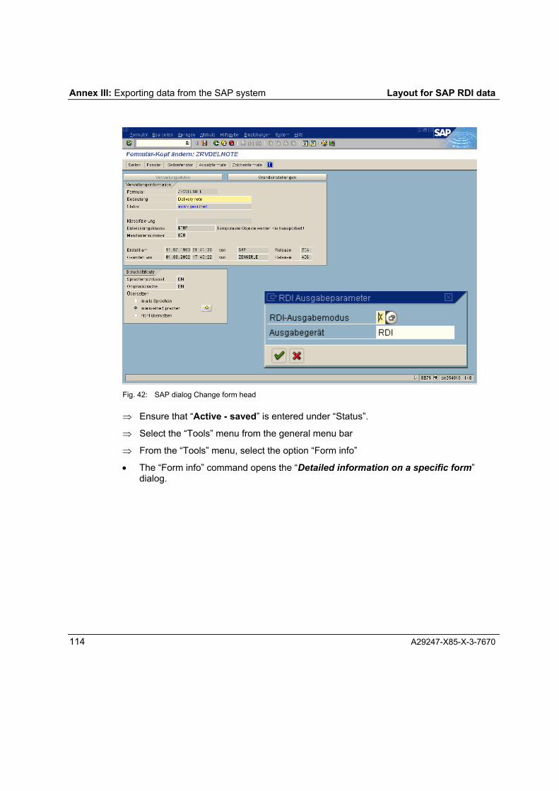
Annex III: Exporting data from the SAP system Layout for SAP RDI data
114 A29247-X85-X-3-7670
Fig. 42: SAP dialog Change form head
⇒ Ensure that �Active - saved� is entered under �Status�.
⇒ Select the �Tools� menu from the general menu bar
⇒ From the �Tools� menu, select the option �Form info�
• The �Form info� command opens the �Detailed information on a specific form�dialog.

Layout for SAP RDI data Annex III: Exporting data from the SAP system
A29247-X85-X-3-7670 115
Fig. 43: SAP dialog �Detailed information on a specific form�
⇒ From the �List� menu, select the �Save to PC file� option, which will open the �Save listto file� option window.
⇒ In the �Save list to file� option window, select the �Unconverted� option. Confirming theoption selection (click a) will open the dialog for selecting a target file.
Fig. 44: Transferring a list to a local file
⇒ Specify the folder where the file is to be transferred (ask the SAP systemadministrator for a suitable path) and start the transfer process by clicking �Transfer�.

Layout for SAP RDI data Annex III: Exporting data from the SAP system
A29247-X85-X-3-7670 116
III.2 Exporting an SAP RDI example file from the SAP system
To export an RDI example file from the SAP system, the same requirements need to bemet as for exporting an SAPscript form file. The requirements and the exit to the SAPsystem are described in Appendix II, Exporting an SAPscript form from the SAP system.
To export an RDI example file, enter the application-dependent transaction name for fileaccess into the command line of the general toolbar in the SAP system window. Therelevant transaction name is available from the SAP system administrator. Calling thistransaction opens the corresponding dialog. The following diagrams show dialogs from anSAP accounts application.
Fig. 45: Application-specific dialog �Change invoice�
⇒ Click the documents button for the invoice number in the dialog �Change invoice� toopen the dialog �Change invoice <invoice no.> (F2):

Layout for SAP RDI data Annex III: Exporting data from the SAP system
A29247-X85-X-3-7670 117
Fig. 46: SAP dialog Messages on the document
⇒ Enter the name of the message type in the overview of the messages under�Message��. The name of the relevant message type (in our example �RD00�) isavailable from the SAP system administrator.
⇒ In the toolbar specific to this dialog, click �Additional information� to open the dialog foradditional information.
⇒ Under �Send type� select �Send immediately� as the send time and return to theprevious dialog by clicking on the 3button in the general toolbar.
⇒ In the toolbar specific to this dialog, click �Communication methods� to open the dialogfor communication methods.
⇒ In the Communication Methods dialog, enter the name for the output to a file definedin the SAP system for �Logical Destination�, select the checkbox �Output Immediately�and enter the name of the relevant SAPscript form (Z...). You can return to theprevious dialog by clicking 3.
⇒ Start the data output process by clicking the Save button in the general toolbar.

Annex III: Exporting data from the SAP system Layout for SAP RDI data
118 A29247-X85-X-3-7670
Fig. 47: SAP dialog Additional information on messages
Fig. 48: SAP dialog Communication methods

Layout for SAP RDI data Annex IV
A29247-X85-X-3-7670 119
IV Functions in Océ Document Designer V1.06In Océ Document Designer V1.06 the following functions are available in the program�Layout for SAP RDI Data� with the functionality described:
Function Functionality Notes / comments
Page sequence Specifies the sequence ofthe page types
FIRST / FIRST % there is only one pagefor the applicationFIRST / NEXT % there are two pages forthe application;the page type FIRST is printed as thefirst page for each RDI document with thepage definitions and the page layout ofthis page type; the next pages of eachRDI document are printed with the pagedefinitions and the page layout of the 2nd
page (page type NEXT)Definition of the page size % Properties % Page typePage definitionSpecifies the page type Possible page types: FIRST, NEXT
Layers Any number of layers can be created foreach page type.Layers can contain images, barcodes,areas and text objects.Layers can be output or not outputdepending on the conditions.
Forms Only forms of the �AFP-Overlay� typePrint direction, position
% Insert % ImageTo be displayed in the Designview, theform must be in EMF format
Area An area defined with itsposition and dimensionsallows the floatingpositioning of fixed dataand float data on layersand in cells
Layer/cell % Insert % AreaArea% Properties % PositionArea% Properties % Position
Outputdefinitions
Print orientation % Properties % Page typeLandscape, portrait

Annex IV: V1.06 Scope of Functions Layout for SAP RDI data
120 A29247-X85-X-3-7670
Function Functionality Notes / comments
Single-/two-sided printing Single-sided; Two-sided; Two-sided,mirrored on short edge; Two-sided, 3rd
and 4th print pages reversed; Two-sided,mirrored on short edge, 3rd and 4th printpage reversed
Pages per sheet 1 page per sheet; 2 pages per sheetPosition of the print page For single-sided:
new sheetFor two-sided:
new sheetnext free partition, current sheetnext free partition, current front sidenext free partition, current back side
Input/output delivery tray Input tray number or input tray nameOutput tray number
Print direction Across, up, down, back % Properties % Text,% Properties % Barcode,% Properties % Image
Character size % Properties % Formatted Text Block
Superscript/Subscript In the range 0.1 to 4.0Character rotation 0 degrees, 90 degrees, 180 degrees, 270
degrees
Characterformatting
Foreground color CustomTone color model(1 = 2nd print unit,other values = 1st print unit)
CustomTone color valueverification number
% Properties % Document TemplateThis ensures that the desired color isavailable in the printer
Color
Text objects Specified in �Formatted Text Block�% Properties % Characters
Font type % Properties % Formatted Text BlockThe Unicode fonts contained in the .dbsfile set via Application Setup areavailable for selection
Font
Font size Unlimited, minimum of 2.0 point

Layout for SAP RDI data Annex IV: V 1.06 Scope of Functions
A29247-X85-X-3-7670 121
Function Functionality Notes / comments
Font style The font styles for the selected fontcontained in the .dbs file set viaApplication Setup are available forselection
Font type % Properties % Formatted Text BlockThe Unicode fonts contained in the .dbsfile set via Application Setup areavailable for selection
Font
Font style The font styles for the selected fontcontained in the .dbs file set viaApplication Setup are available forselection
Assignment of• constant texts• fields• system variables
Constant texts:Character sequence of any length, noline wrappingFields:Data references from design data;an additional preceding and/or followingspace is possible; a freely-selectedpartial string can be outputSystem variables:Page number, number of pages
Text objects
Positioning In a cell:fixed positioning by specifying the verticaland horizontal position in the cell, flushright or leftIn a layer:fixed positioning by specifying the verticaland horizontal position in the layer, flushright or leftIn a frame, float area or loop:vertical float position is determined byindicating the horizontal position andvertical distance to the prior element
Borders andLines
Availability Borders and lines can be drawn on thefollowing levels:
• Table• Row (header, base and footer rows)• Cell

Annex IV: V1.06 Scope of Functions Layout for SAP RDI data
122 A29247-X85-X-3-7670
Function Functionality Notes / comments
Scope The specifications apply to the following:• Top margin• Bottom margin• Right margin• Left margin
Line type border • None (i.e. for the margin where thisvalue is selected, no line is drawn.This can be used, for example, tounderline a header row or draw adividing line between two differentMAIN fieldgroups)
• SolidLine thicknessColor model per line CustomTone color model
(1 = 2nd print unit,other values = 1st print unit)
Availability The shading function is available on thefollowing levels:• Table• Row (header, base and footer rows)• Cell
Color coverage Specified in %
Shading
Color model, foreground CustomTone color model(1 = 2nd print unit,other values = 1st print unit)
Loops Group-defined tables:assignment of the group references tomap the repetition structureStatic tables:no loops
Header Printed at the beginning of a float area(also on subsequent pages)
Table
Row (base row) Static tables:each created row is only printed onceGroup-defined tables:Mapping of the repeated structure of agroup, i.e. the row is generated as manytimes as there are instances of this groupwithin an RDI document

Layout for SAP RDI data Annex IV: V 1.06 Scope of Functions
A29247-X85-X-3-7670 123
Function Functionality Notes / comments
Footer Printed at the end of a float area (on allpages over which the table extends)
Row height % Properties % Header/Row/FooterThe height of the row is defined for eachrow and each row type (header, base,footer row)
Position % Properties % TablePositioning of the table in the float area:specification of the horizontal positionand the vertical distance to the previouslypositioned element
Cells Division of a table row into columns withspecification of the cell width
Constant texts and fields The characters to be displayed as abarcode are produced by linking anynumber of constant texts and fields (datareferences).Data references can additionally bepreceded / followed by a space.
Parameters for code 128 The following parameters can be set bythe user:a) Print direction (across, up, back,
down)b) Module width [7mm, 254 mm]c) Module height [5mm, 1000mm]d) HRI (none / standard)The following are fixed for code 128:a) Generation with checksumb) Font of the HRI (print standard for
BCOCA)
Barcode
Positioning Barcodes can only be positioned fixed ona layer. The coordinates (X,Y) describethe position of the top left corner of thebarcode symbol on the page to which thelayer is assigned.

Annex IV: V1.06 Scope of Functions Layout for SAP RDI data
124 A29247-X85-X-3-7670
Function Functionality Notes / comments
Fixed data Fixed data are all design data that arenot below the MAIN group and itssubgroups, and are not defined in arepeating structure for implementinginclude statements.Fixed data can be referenced:• on the layer (ODD Layout Editor)• in the float area before tables, between
2 tables and after a table• in the float area in tables (in the cell)
Float data Float data (relative data references) areall the design data defined below theMAIN group or the fieldgroups of MAIN.Float data can be referenced in:• Loops• Group-defined tables (not static tables;
mapping of the repeated structure inloops).
Referencing ofdata fields
Include data Include data are data that appear in theRDI data via the SAPscript instruction�INCLUDE�.The include data can appear inside andoutside of MAIN and can contain anynumber of rows of data. These rows arenot assigned to a field reference in theRDI data. The include data are mappedin the design data via a repeatedstructure. Include data can be referencedin:• Loops• Group-defined tables (not static tables;
mapping of the repeated structure byloops).

Layout for SAP RDI data Annex IV: V 1.06 Scope of Functions
A29247-X85-X-3-7670 125
The current set of functions in the �Layout for SAP RDI Data� allows for example data-dependent address formatting adapted to country-specific standards.
Address formatting:With the aid of the frame object and the conditional formatting,
• addresses can be formatted for each country
• addresses can be formatted with a P.O. box or street depending on the RDI data,
• empty data references can be suppressed.
Layout for SAP RDI data
A29247-X85-X-3-7670 126
Index
Application frame 11Barcode 8CAP 18Constant string 8Default properties 31Designview 22Designview selection bar 23Editing properties 22Field 8Float area 6Formatted block 7General toolbar 15Graphic 8Head 8Insert object 45Layer 7Layout document window 18Layout program window 10Menu bar 11
NUM 18Object properties 31Object toolbar 16Paste bar 19Properties 31Properties dialog 24Rename 22Row 8SAPscript form 6Selection 21Status bar 18Table 8Tail 8Text 7Toolbar 15Treeview 18User interface 9Workspace 18

A29247-X85-X-3-7670 127