Modern Design Principles for Numerical Busbar Differential...
16
Modern Design Principles for Numerical Busbar Differential Protection Zoran Gajić, Hamdy Faramawy, Li He, Klas Koppari, Lee Max ABB AB Västerås, Sweden [email protected] Mike Kockott ABB Inc. Raleigh, NC, USA Summary For busbar protection, it is extremely important to have good security since an unwanted operation might have severe consequences. The unwanted operation of the bus differential relay will have the similar effect as simultaneous faults on all power system elements connected to the bus. On the other hand, the relay has to be dependable as well. Failure to operate or even slow operation of the differential relay, in case of an actual internal fault, can have fatal consequences. These two requirements are contradictory to each other. To design the differential relay to satisfy both requirements at the same time is not an easy task. Busbar protection shall also be able to dynamically include and/or exclude individual bay currents from differential zones. Therefore it must contain so-called dynamic zone selection in order to adapt to changing topology of substation for multi-zone applications. The software based dynamic zone selection ensures: 1. Dynamic linking of measured bay currents to the appropriate differential protection zone(s) as required by substation topology. Efficient merging of differential zones when required by substation topology (that is, zone interconnection or load-transfer). 2. Easy zone merging initiated externally by closing of bus-sectionalizing disconnectors. 3. Selective operation of busbar differential protection to ensure tripping only of circuit breakers connected to the faulty zone. 4. Selective tripping for circuit breaker failure protection. 5. Correct marshaling of backup-trip commands from internally integrated or external circuit breaker failure protections to all surrounding circuit breakers. 6. Easy incorporation of bus-section and/or bus-coupler bays (that is, tie-breakers) with one or two sets of CTs into the protection scheme. 7. Disconnector and/or circuit breaker status supervision. Modern design for a Busbar Differential Protection IED [10] containing six differential protection zones and fulfilling all of the above mentioned requirements will be presented in the paper. Keywords Busbar Protection, Differential Protection, Dynamic Zone Selection. I INTRODUCTION The bus zone protection has experienced several decades of changes. It is fair to say that the first introduction of bus zone protection in Europe started in Britain as early as 1904. This was known as the circulating current Merz-Price system [7]. Later, in the beginning of the 1940s, the high impedance differential protection scheme was introduced [1]. One of the main features of the high impedance differential scheme is that it permits the faulty line current transformer (CT) to be fully saturated in the event of a severe external fault and still keep the stability. However, in order to fulfil this requirement, it demands that all CT cores connected to one protection zone have to have the same ratio and the same magnetizing characteristics.
Transcript of Modern Design Principles for Numerical Busbar Differential...
Modern Design Principles for Numerical BusbarDifferential Protection
Zoran Gajić, Hamdy Faramawy, Li He, KlasKoppari, Lee MaxABB AB
Västerås, Sweden
Mike KockottABB Inc.
Raleigh, NC, USA
Summary
For busbar protection, it is extremely important to havegood security since an unwanted operation might have severeconsequences. The unwanted operation of the bus differentialrelay will have the similar effect as simultaneous faults on allpower system elements connected to the bus. On the otherhand, the relay has to be dependable as well. Failure to operateor even slow operation of the differential relay, in case of anactual internal fault, can have fatal consequences. These tworequirements are contradictory to each other. To design thedifferential relay to satisfy both requirements at the same timeis not an easy task.
Busbar protection shall also be able to dynamicallyinclude and/or exclude individual bay currents fromdifferential zones. Therefore it must contain so-calleddynamic zone selection in order to adapt to changing topologyof substation for multi-zone applications. The software baseddynamic zone selection ensures:
1. Dynamic linking of measured bay currents to theappropriate differential protection zone(s) as required bysubstation topology. Efficient merging of differential zoneswhen required by substation topology (that is, zoneinterconnection or load-transfer).
2. Easy zone merging initiated externally by closing ofbus-sectionalizing disconnectors.
3. Selective operation of busbar differential protection toensure tripping only of circuit breakers connected to the faultyzone.
4. Selective tripping for circuit breaker failureprotection.
5. Correct marshaling of backup-trip commands frominternally integrated or external circuit breaker failureprotections to all surrounding circuit breakers.
6. Easy incorporation of bus-section and/or bus-couplerbays (that is, tie-breakers) with one or two sets of CTs into theprotection scheme.
7. Disconnector and/or circuit breaker status supervision.
Modern design for a Busbar Differential Protection IED[10] containing six differential protection zones and fulfillingall of the above mentioned requirements will be presented inthe paper.
Keywords
Busbar Protection, Differential Protection, Dynamic ZoneSelection.
I INTRODUCTION
The bus zone protection has experienced several decadesof changes. It is fair to say that the first introduction of buszone protection in Europe started in Britain as early as 1904.This was known as the circulating current Merz-Price system[7]. Later, in the beginning of the 1940s, the high impedancedifferential protection scheme was introduced [1]. One of themain features of the high impedance differential scheme isthat it permits the faulty line current transformer (CT) to befully saturated in the event of a severe external fault and stillkeep the stability. However, in order to fulfil this requirement,it demands that all CT cores connected to one protection zonehave to have the same ratio and the same magnetizingcharacteristics.
As a result of the requirements from central Europe to copewith different CT ratios within one protection zone, thepercentage restrained differential protection scheme, based ona special analog circuit, was developed in the late 1960s [2].
Although successful in practice, both of the abovementioned analog differential relays have some shortcomingssuch as the need for auxiliary CTs to match the different CTratios, the lack of self-supervision, secondary CT switchingfor double or multiple busbar arrangements and relativelycomplicated scheme engineering.
II PRINCIPLES OF DIFFERENTIAL PROTECTION
The basic concept for any bus differential relay is that thesum of all currents, which flow into the protection zone, mustbe equal to the sum of all currents, which flow out of theprotection zone. If that is not the case, an internal fault hasoccurred. This is practically a direct use of Kirchhoff’s firstlaw, which is taught in the “Basics of Electricity” during thefirst year of electrical engineering studies. Unfortunately,practice is often different and more difficult than the theory inthe books.
Magnetic core current transformers
Bus differential relays do not measure directly the primarycurrent in the high voltage conductors, but instead thesecondary current from magnetic cores positioned inside CTs,which are installed in all high-voltage bays. Because thecurrent transformer is a non-linear measuring device, underhigh current conditions in the primary CT circuit thesecondary CT current can be drastically different from theoriginal primary current.
This is caused by CT saturation, a phenomenon that is wellknown to protection engineers [6]. It is especially relevant forbus differential protection applications, because it has thetendency to cause unwanted operation of the differential relay.
Remanence in the magnetic core of a current transformeris an additional factor, which can influence the secondary CTcurrent. It can improve or reduce the capability of the currenttransformer to properly transfer the primary current to thesecondary side. However the CT remanence is a randomparameter and it is not possible in practice to preciselydetermine it.
Analog differential protection
The high impedance differential relay generally solves allpractical problems caused by the CT non-linear characteristicsby using the galvanic connection between the secondarycircuits of all CTs connected to the protected zone. Thescheme is designed in such a way that the current distributionthrough the differential branch during all transient conditionscaused by nonlinearity of the CTs will not cause the unwantedoperation of the differential relay. This is achieved byconnecting a high impedance (usually resistance) in serieswith the operating element of the differential relay. Thisimpedance will then limit the level of false differential currentthrough the differential branch. To obtain the optimum relayperformance, the resistive burden in the individual CTsecondary circuits must be kept low and should have a similarvalue in all bays.
At the same time no other relays can be connected to thesame CT core. Due to the lack of any restraint quantity, it isstrongly required that all current transformers within onedifferential zone have to have the same ratio and the samemagnetizing characteristic. All these requirements imposeadditional expense to the power utility in order to purchasespecially made CT cores used for the bus differentialprotection only. However if all of the above conditions aremet, this scheme is quite reliable and very sensitive. Its usualoperating times for internal faults are below one power systemcycle [1].
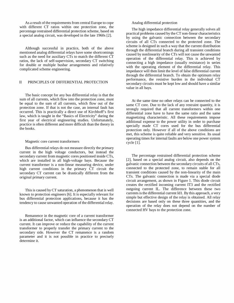
The percentage restrained differential protection scheme[2], based on a special analog circuit, also depends on thegalvanic connection between the secondary circuits of all CTs,connected to the protected zone, to remain stable for alltransient conditions caused by the non-linearity of the mainCTs. The galvanic connection is made via a special diodecircuit arrangement, as shown in Figure 1. This diode circuitcreates the rectified incoming current IT3 and the rectifiedoutgoing current IL. The difference between these twocurrents is the differential current Id1. By this approach, a verysimple but effective design of the relay is obtained. All relaydecisions are based only on these three quantities, and theoperation of the relay does not depend on the number ofconnected HV bays to the protection zone.
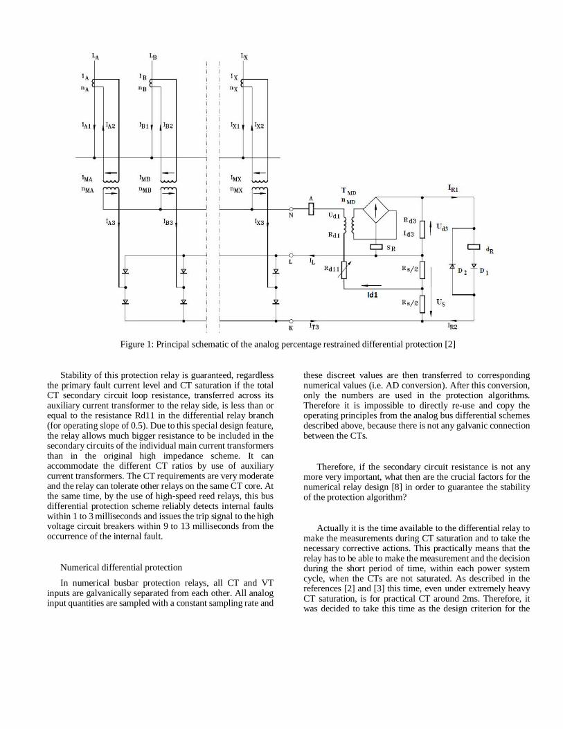
Figure 1: Principal schematic of the analog percentage restrained differential protection [2]
Stability of this protection relay is guaranteed, regardlessthe primary fault current level and CT saturation if the totalCT secondary circuit loop resistance, transferred across itsauxiliary current transformer to the relay side, is less than orequal to the resistance Rd11 in the differential relay branch(for operating slope of 0.5). Due to this special design feature,the relay allows much bigger resistance to be included in thesecondary circuits of the individual main current transformersthan in the original high impedance scheme. It canaccommodate the different CT ratios by use of auxiliarycurrent transformers. The CT requirements are very moderateand the relay can tolerate other relays on the same CT core. Atthe same time, by the use of high-speed reed relays, this busdifferential protection scheme reliably detects internal faultswithin 1 to 3 milliseconds and issues the trip signal to the highvoltage circuit breakers within 9 to 13 milliseconds from theoccurrence of the internal fault.
Numerical differential protection
In numerical busbar protection relays, all CT and VTinputs are galvanically separated from each other. All analoginput quantities are sampled with a constant sampling rate and
these discreet values are then transferred to correspondingnumerical values (i.e. AD conversion). After this conversion,only the numbers are used in the protection algorithms.Therefore it is impossible to directly re-use and copy theoperating principles from the analog bus differential schemesdescribed above, because there is not any galvanic connectionbetween the CTs.
Therefore, if the secondary circuit resistance is not anymore very important, what then are the crucial factors for thenumerical relay design [8] in order to guarantee the stabilityof the protection algorithm?
Actually it is the time available to the differential relay tomake the measurements during CT saturation and to take thenecessary corrective actions. This practically means that therelay has to be able to make the measurement and the decisionduring the short period of time, within each power systemcycle, when the CTs are not saturated. As described in thereferences [2] and [3] this time, even under extremely heavyCT saturation, is for practical CT around 2ms. Therefore, itwas decided to take this time as the design criterion for the
minimum acceptable time before saturation of a practicalmagnetic CT cores.
However, if the necessary preventive action has to betaken for every single HV bay connected to the protectionzone, the relay algorithm would be quite complex. Therefore,it was decided to try to re-use the important quantities fromthe analog percentage restrained differential protection relay,like incoming, outgoing and differential currents, within thenumerical design. These three quantities can be easilycalculated numerically from the raw sample values from allanalog CT inputs connected to the differential zone. At thesame time, they have extremely valuable physical meaning,which clearly describes the condition of the protected zoneduring all operating conditions.
By using the properties of only these three quantities, adifferential algorithm has been formed which is completelystable for all external faults and very fast for the internal faults.This differential algorithm is already proven in severalthousands of installations all over the world. All problemscaused by the nonlinearity of the CTs are solved in aninnovative numerical way on the basic principles describedabove. Detailed description of this algorithm is available inreference [8].
III DYNAMIC ZONE SELECTION FOR COMPLEXSTATION LAYOUTS
Efficient dynamic zone selection, referred also sometimesin the relay literature as busbar replica, is a key function forcomplex busbar arrangements where one bay can bedynamically associated with several differential protectionzones. In such installations CT connections towards theprotection zones will vary over time. Therefore it is importantthat CT connections towards the protection zones are properlyselected. Many methods have been developed to provideadvanced dynamic zone selection to cope with the increasedcomplexity and flexibility. For example graphicalrepresentation of busbar topology, zone selection based ongraph theory, etc. where proposed. New simple andcomputationally efficient alternative has been proposed in [9]and implemented in latest generation of numerical busbarprotection [10].
Main features of the new implemented algorithm are:
1. Applicable for up to six freely configurabledifferential protection zones and up to twenty-four freelyconfigurable CTs.
2. Applicable for single, double and triple busbararrangements with or without transfer bus.
3. Applicable for double circuit breaker or one-and-halfcircuit breaker stations.
4. Easy incorporation of bus-section and/or bus-couplerbays (that is, tie-breakers) with one or two sets of main CTs.
5. Easy incorporation of bus-sectionalizingdisconnectors.
6. Easy scheme engineering including even the futurebays.
The integrated zone selection component requiresinformation of several different types at different levels:
1. The static configuration information. It concerns, forinstance, the type and operation mode of each bay, themaximum number of used protection zones, etc.
2. Dynamic data which affects the interconnection of buszones dynamically. It concerns the operational status of thedisconnectors located at each individual bay and bussectionalizing disconnectors, together with operational statusof bays (e.g. bay out of service).
The integrated zone selection component ensures thedynamical adaptability to most common busbarconfigurations by:
1. Accurate dynamic linking of measured bay CTcurrents to appropriate differential protection zones.
2. Selective routing of busbar differential protectionzones trip commands to only the circuit breakers connected tothe faulty zone.
3. Selective tripping for circuit breaker failure protectionby correct marshaling of backup-trip commands frominternally integrated or externally located circuit breakerfailure protections to all surrounding circuit breakers.
4. Efficient zone interconnection (i.e. load-transfer),which in principle is a merging of the two or more differentialzones when required by substation actual topology.
5. Easy handling of bus-sectionalizing disconnectors.
6. Disconnector and/or circuit breaker status supervisionand alarming.
In addition, so-called parallel connection, which occurs ata bus-section bay or a bus-coupler bay when both of its endsare assigned to the same protection zone is also easily handledin new design. The zone selection algorithm then ensures thatboth currents from a bus-section bay or a bus-coupler bay are
taken out from the respective zone(s) of the differentialprotection. In addition, there is possibility for the end user todetermine by a setting if a tripping is allowed for the bus-section or bus-coupler circuit breaker while there is a parallelconnection in progress.
IV RTDS TEST SETUP
Real Time Digital Simulator, RTDS was used to createand run the test cases for new busbar protection (i.e. BBP)with six differential zones and new Zone Selection [10]. Theused network topologies and test cases are included in comingsections of this document.
RTDS is a Real Time Digital Simulator which has thecapability of simulating the power system in real time. Realtime means that we can operate a breaker, force a fault, ormake any change in the power system and evaluate BBPbehavior for the same disturbance in real time. This is possible
due to several processing units that are utilized in parallelwhich give the RTDS a high computational power. Thecalculations are done in every time step, with typical stepvalue lying between 50µs and 120µs. Testing is performed intwo parts: functional and dynamic.
Functional tests are intended to verify the ability of busbarprotection function to clear all internal faults with absoluteselectivity. Faults are simulated under different switchgearconfigurations and at different location. The protectionfunction has behaved correctly during all tests cases.
Substation switchgear arrangement used to run functionaltest cases is shown in Figure 3.
The dynamic tests are performed to evaluate BBPbehavior during different transient processes (e.g. CTsaturation).
Figure 2: RTDS setup
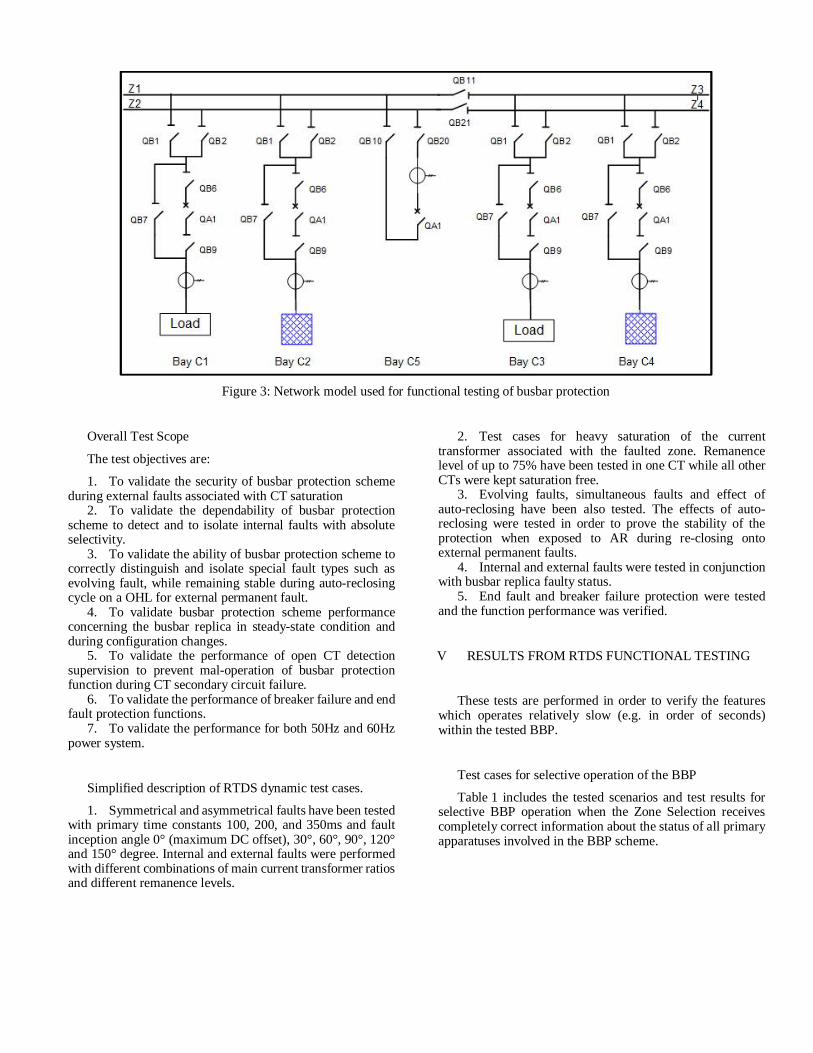
Figure 3: Network model used for functional testing of busbar protection
Overall Test Scope
The test objectives are:
1. To validate the security of busbar protection schemeduring external faults associated with CT saturation
2. To validate the dependability of busbar protectionscheme to detect and to isolate internal faults with absoluteselectivity.
3. To validate the ability of busbar protection scheme tocorrectly distinguish and isolate special fault types such asevolving fault, while remaining stable during auto-reclosingcycle on a OHL for external permanent fault.
4. To validate busbar protection scheme performanceconcerning the busbar replica in steady-state condition andduring configuration changes.
5. To validate the performance of open CT detectionsupervision to prevent mal-operation of busbar protectionfunction during CT secondary circuit failure.
6. To validate the performance of breaker failure and endfault protection functions.
7. To validate the performance for both 50Hz and 60Hzpower system.
Simplified description of RTDS dynamic test cases.
1. Symmetrical and asymmetrical faults have been testedwith primary time constants 100, 200, and 350ms and faultinception angle 0° (maximum DC offset), 30°, 60°, 90°, 120°and 150° degree. Internal and external faults were performedwith different combinations of main current transformer ratiosand different remanence levels.
2. Test cases for heavy saturation of the currenttransformer associated with the faulted zone. Remanencelevel of up to 75% have been tested in one CT while all otherCTs were kept saturation free.
3. Evolving faults, simultaneous faults and effect ofauto-reclosing have been also tested. The effects of auto-reclosing were tested in order to prove the stability of theprotection when exposed to AR during re-closing ontoexternal permanent faults.
4. Internal and external faults were tested in conjunctionwith busbar replica faulty status.
5. End fault and breaker failure protection were testedand the function performance was verified.
V RESULTS FROM RTDS FUNCTIONAL TESTING
These tests are performed in order to verify the featureswhich operates relatively slow (e.g. in order of seconds)within the tested BBP.
Test cases for selective operation of the BBP
Table 1 includes the tested scenarios and test results forselective BBP operation when the Zone Selection receivescompletely correct information about the status of all primaryapparatuses involved in the BBP scheme.
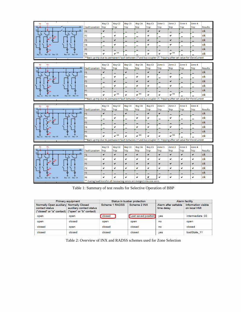
Table 1: Summary of test results for Selective Operation of BBP
Table 2: Overview of INX and RADSS schemes used for Zone Selection
Test cases with incorrect information into zone selectionlogic
Information about the topology of the protected station ismandatory for the proper assignment of current transformer tothe respective protection zones and selective clearance duringfaults. The tested BBP offers two different operatingprinciples to deduce the position of a primary apparatus (i.e.either disconnector or circuit breaker) in case when status oftwo auxiliary contacts is lost. Treatment of primary apparatusauxiliary contact status for the two principles available withinthe tested BBP is shown in Table 2.
Remarks on incorrect bus replica test results
As seen from Table 2 above, the difference between thetwo schemes used for bus replica is only how an intermediateposition (i.e. “00”) of any primary apparatus has beeninterpreted.
RADSS scheme works on the principle if not open thenclosed, while INX scheme uses the last saved valid position.
From the application point of view RADSS schememaintain security and lacks selectivity, as all the object withintermediate position is treated as closed, which typicallyresults in zone merging.
On the other hand, INX scheme maintain selectivity andlacks security under specific circumstances when the positionof the primary apparatus does not represent the actual positionanymore. Hence, INX scheme requires that while theswitchgear alarm signal is active, it shall not be permitted tooperate any other isolator or circuit-breaker in the station. Asthe isolators require a certain time to operated, alarm relatedto the position is time delayed.
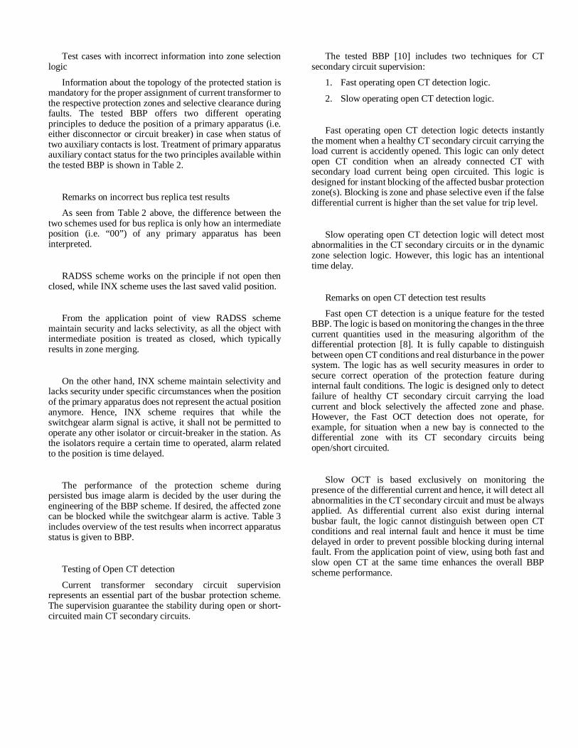
The performance of the protection scheme duringpersisted bus image alarm is decided by the user during theengineering of the BBP scheme. If desired, the affected zonecan be blocked while the switchgear alarm is active. Table 3includes overview of the test results when incorrect apparatusstatus is given to BBP.
Testing of Open CT detection
Current transformer secondary circuit supervisionrepresents an essential part of the busbar protection scheme.The supervision guarantee the stability during open or short-circuited main CT secondary circuits.
The tested BBP [10] includes two techniques for CTsecondary circuit supervision:
1. Fast operating open CT detection logic.
2. Slow operating open CT detection logic.
Fast operating open CT detection logic detects instantlythe moment when a healthy CT secondary circuit carrying theload current is accidently opened. This logic can only detectopen CT condition when an already connected CT withsecondary load current being open circuited. This logic isdesigned for instant blocking of the affected busbar protectionzone(s). Blocking is zone and phase selective even if the falsedifferential current is higher than the set value for trip level.
Slow operating open CT detection logic will detect mostabnormalities in the CT secondary circuits or in the dynamiczone selection logic. However, this logic has an intentionaltime delay.
Remarks on open CT detection test results
Fast open CT detection is a unique feature for the testedBBP. The logic is based on monitoring the changes in the threecurrent quantities used in the measuring algorithm of thedifferential protection [8]. It is fully capable to distinguishbetween open CT conditions and real disturbance in the powersystem. The logic has as well security measures in order tosecure correct operation of the protection feature duringinternal fault conditions. The logic is designed only to detectfailure of healthy CT secondary circuit carrying the loadcurrent and block selectively the affected zone and phase.However, the Fast OCT detection does not operate, forexample, for situation when a new bay is connected to thedifferential zone with its CT secondary circuits beingopen/short circuited.
Slow OCT is based exclusively on monitoring thepresence of the differential current and hence, it will detect allabnormalities in the CT secondary circuit and must be alwaysapplied. As differential current also exist during internalbusbar fault, the logic cannot distinguish between open CTconditions and real internal fault and hence it must be timedelayed in order to prevent possible blocking during internalfault. From the application point of view, using both fast andslow open CT at the same time enhances the overall BBPscheme performance.
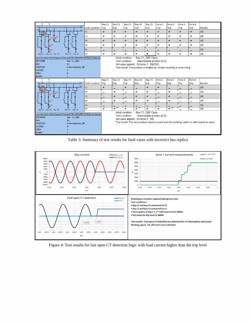
Table 3: Summary of test results for fault cases with incorrect bus replica
Figure 4: Test results for fast open CT detection logic with load current higher than the trip level
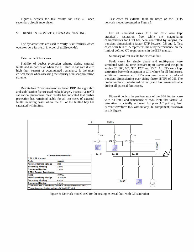
Figure 4 depicts the test results for Fast CT opensecondary circuit supervision.
VI RESULTS FROM RTDS DYNAMIC TESTING
The dynamic tests are used to verify BBP features whichoperates very fast (e.g. in order of milliseconds).
External fault test cases
Stability of busbar protection scheme during externalfaults and in particular when the CT start to saturate due tohigh fault current or accumulated remanence is the mostcritical factor when assessing the security of busbar protectionscheme.
Despite low CT requirement for tested BBP, the algorithmand stabilization feature used make it largely insensitive to CTsaturation phenomena. Test results has indicated that busbarprotection has remained stable for all test cases of externalfaults including cases where the CT of the faulted bay hassaturated within 2ms.
Test cases for external fault are based on the RTDSnetwork model presented in Figure 5.
For all simulated cases, CT1 and CT2 were keptpractically saturation free while the magnetizingcharacteristics for CT3 has been controlled by varying thetransient dimensioning factor KTF between 0.5 and 2. Testcases with KTF=0.5 represents the relay performance on thelimit of defined CT requirements in the BBP manual.
Summary of test results for external fault
Fault cases for single phase and multi-phase weresimulated with DC time constant up to 350ms and inceptionangles 0°, 30°, 60°, 90°, 120° and 150°. All CTs were keptsaturation free with exception of CT3 where for all fault cases,additional remanence of 75% was used even at a reducedtransient dimensioning over sizing factor (KTF) of 0.5. Theprotection function behaved correctly and has remained stableduring all external fault cases.
Figure 6 depicts the performance of the BBP for test casewith KTF=0.5 and remanence of 75%. Note that fastest CTsaturation is actually achieved for pure AC primary faultcurrent waveform (i.e. without any DC component) as shownin this figure.
Figure 5: Network model used for the testing external fault with CT saturation
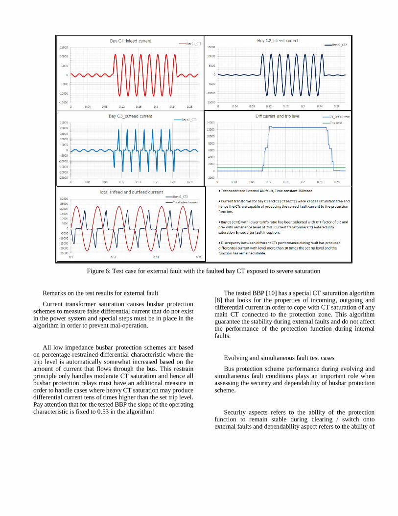
Figure 6: Test case for external fault with the faulted bay CT exposed to severe saturation
Remarks on the test results for external fault
Current transformer saturation causes busbar protectionschemes to measure false differential current that do not existin the power system and special steps must be in place in thealgorithm in order to prevent mal-operation.
All low impedance busbar protection schemes are basedon percentage-restrained differential characteristic where thetrip level is automatically somewhat increased based on theamount of current that flows through the bus. This restrainprinciple only handles moderate CT saturation and hence allbusbar protection relays must have an additional measure inorder to handle cases where heavy CT saturation may producedifferential current tens of times higher than the set trip level.Pay attention that for the tested BBP the slope of the operatingcharacteristic is fixed to 0.53 in the algorithm!
The tested BBP [10] has a special CT saturation algorithm[8] that looks for the properties of incoming, outgoing anddifferential current in order to cope with CT saturation of anymain CT connected to the protection zone. This algorithmguarantee the stability during external faults and do not affectthe performance of the protection function during internalfaults.
Evolving and simultaneous fault test cases
Bus protection scheme performance during evolving andsimultaneous fault conditions plays an important role whenassessing the security and dependability of busbar protectionscheme.
Security aspects refers to the ability of the protectionfunction to remain stable during clearing / switch ontoexternal faults and dependability aspect refers to the ability of
the protection function to detect and operate for all internalfaults even including the faults which may evolve fromexternal to internal.
Summary for fault cases and test results for evolving fault
Following are the test cases included in the test scope:
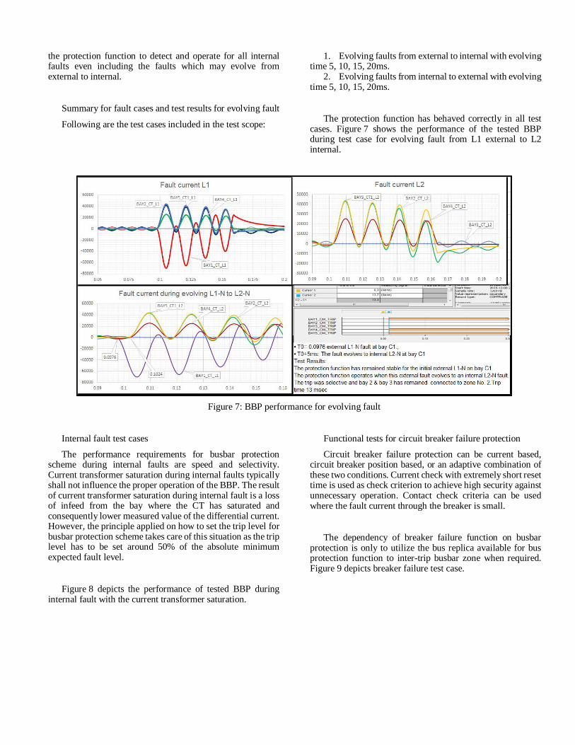
1. Evolving faults from external to internal with evolvingtime 5, 10, 15, 20ms.
2. Evolving faults from internal to external with evolvingtime 5, 10, 15, 20ms.
The protection function has behaved correctly in all testcases. Figure 7 shows the performance of the tested BBPduring test case for evolving fault from L1 external to L2internal.
Figure 7: BBP performance for evolving fault
Internal fault test cases
The performance requirements for busbar protectionscheme during internal faults are speed and selectivity.Current transformer saturation during internal faults typicallyshall not influence the proper operation of the BBP. The resultof current transformer saturation during internal fault is a lossof infeed from the bay where the CT has saturated andconsequently lower measured value of the differential current.However, the principle applied on how to set the trip level forbusbar protection scheme takes care of this situation as the triplevel has to be set around 50% of the absolute minimumexpected fault level.
Figure 8 depicts the performance of tested BBP duringinternal fault with the current transformer saturation.
Functional tests for circuit breaker failure protection
Circuit breaker failure protection can be current based,circuit breaker position based, or an adaptive combination ofthese two conditions. Current check with extremely short resettime is used as check criterion to achieve high security againstunnecessary operation. Contact check criteria can be usedwhere the fault current through the breaker is small.
The dependency of breaker failure function on busbarprotection is only to utilize the bus replica available for busprotection function to inter-trip busbar zone when required.Figure 9 depicts breaker failure test case.
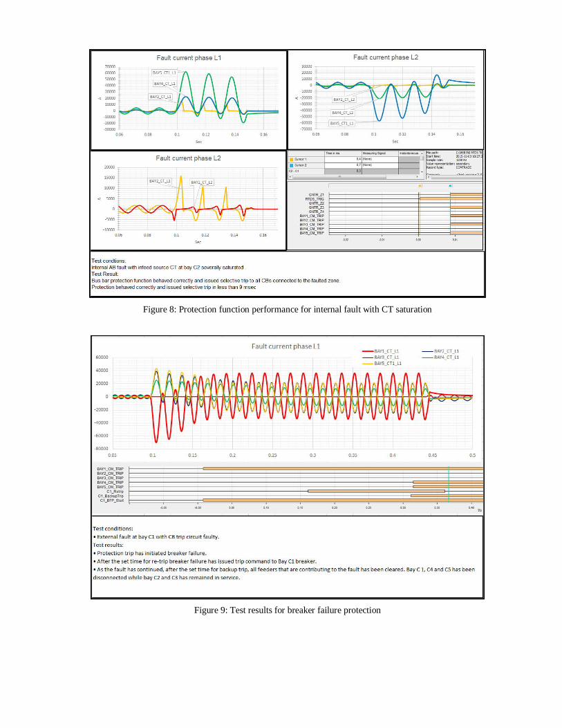
Figure 8: Protection function performance for internal fault with CT saturation
Figure 9: Test results for breaker failure protection
VII OPERATION EXPERIENCE IN THE FIELD
The used differential protection algorithm, which ispresented in more details in reference [8], has been applied formore than ten years in several thousands of BBP installationsall around the world. Many operations for actual internalfaults have been recorded and some of them will be presentedin this section.
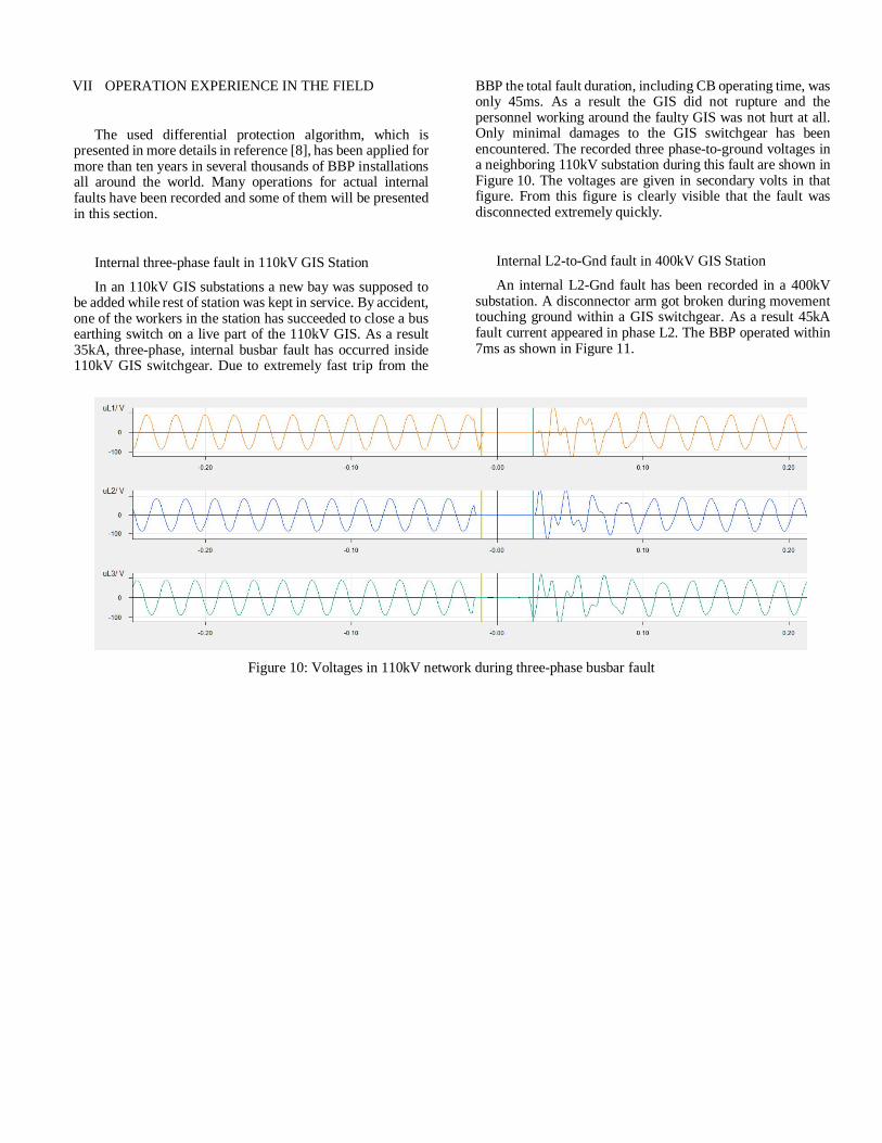
Internal three-phase fault in 110kV GIS Station
In an 110kV GIS substations a new bay was supposed tobe added while rest of station was kept in service. By accident,one of the workers in the station has succeeded to close a busearthing switch on a live part of the 110kV GIS. As a result35kA, three-phase, internal busbar fault has occurred inside110kV GIS switchgear. Due to extremely fast trip from the
BBP the total fault duration, including CB operating time, wasonly 45ms. As a result the GIS did not rupture and thepersonnel working around the faulty GIS was not hurt at all.Only minimal damages to the GIS switchgear has beenencountered. The recorded three phase-to-ground voltages ina neighboring 110kV substation during this fault are shown inFigure 10. The voltages are given in secondary volts in thatfigure. From this figure is clearly visible that the fault wasdisconnected extremely quickly.
Internal L2-to-Gnd fault in 400kV GIS Station
An internal L2-Gnd fault has been recorded in a 400kVsubstation. A disconnector arm got broken during movementtouching ground within a GIS switchgear. As a result 45kAfault current appeared in phase L2. The BBP operated within7ms as shown in Figure 11.
Figure 10: Voltages in 110kV network during three-phase busbar fault
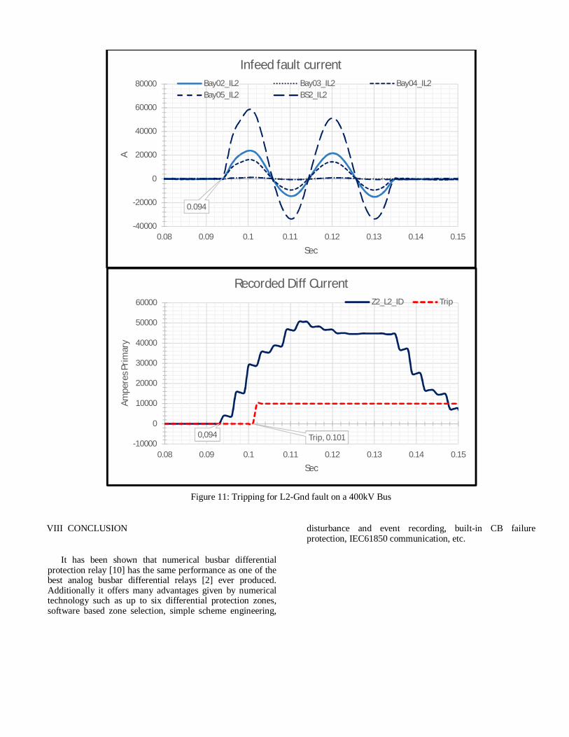
Figure 11: Tripping for L2-Gnd fault on a 400kV Bus
VIII CONCLUSION
It has been shown that numerical busbar differentialprotection relay [10] has the same performance as one of thebest analog busbar differential relays [2] ever produced.Additionally it offers many advantages given by numericaltechnology such as up to six differential protection zones,software based zone selection, simple scheme engineering,
disturbance and event recording, built-in CB failureprotection, IEC61850 communication, etc.
0.094
-40000
-20000
0
20000
40000
60000
80000
0.08 0.09 0.1 0.11 0.12 0.13 0.14 0.15
A
Sec
Infeed fault currentBay02_IL2 Bay03_IL2 Bay04_IL2Bay05_IL2 BS2_IL2
0,094 Trip, 0.101-10000
0
10000
20000
30000
40000
50000
60000
0.08 0.09 0.1 0.11 0.12 0.13 0.14 0.15
Ampe
res P
rimar
y
Sec
Recorded Diff CurrentZ2_L2_ID Trip
IX BIBLIOGRAPHY
[1] H.T. Seeley and F. Van Roeschlaub, “InstantaneousBus-Differential Protection Using Bushing CurrentTransformers”, AIEE Transaction, Vol. 67, 1948.
[2] T. Forford and J.R. Linders, “A Half Cycle BusDifferential Relay and its Application”, IEEE Transaction onPower Apparatus and Systems, Vol.PAS-93, July/Aug. 1974.
[3] T. Forford, “High Speed Differential Protection forLarge Generators”, IEE Conference on Developments inPower System Protection, London, UK, June 1980
[4] J. Esztergalyos, J. Bertsch and M. Ilar, “Performanceof a Busbar Differential Protection Based on EMTPSimulation and Digital System Tests”, 24th Annual WesternProtective Relay Conference, Spokane, Washington, Oct.1997.
[5] A. Kumar and P. Hansen, “Digital Bus ZoneProtection”, IEEE Computer Application in Power, Oct. 1993.
[6] V. Gharpure, J. Horak and B. Shulim, “Bus ProtectiveRelaying, Methods and Application”, 53rd Annual GeorgiaTech Protective Relay Conference, Atlanta, Georgia, May1999.
[7] Wright and C. Christopoulos, “Electrical PowerSystem Protection”, Chapman & Hall, first edition, 1993.
[8] Z. Gajic, “Design principles of high performancenumerical busbar differential protection”, Relay Protectionand Substation Automation of Modern Power Systems,Cheboksary-Russia, September 9-13, 2007
[9] Li He, “Method and device for protection zoneselection in a multiple busbar arrangement”.WO2012175108A1, 27 Dec. 2012
[10] ABB, “Technical Manual for Busbar ProtectionREB670 Version 2.2”
X AUTHORS
Zoran Gajić
Zoran is a Senior Application Engineer at ABB AB, GridAutomation Products in Vasteras, Sweden. He received hisMSEE degree with honors from the University of Belgrade,Serbia in 1990 and PhD degree in electrical engineering fromLund University, Sweden in 2008. Since 1993 he has beenworking in the area of power system protection and controlwithin ABB Group of companies, where he had variousengineering positions. From 2008 to 2015 he was ABB GlobalProduct Manager for Generator and Transformer Protection.He has published many technical papers in the relay protectionarea and holds more than fifteen patents. Zoran has participatedin different CIGRE, IEC and PSRC/IEEE working groups andwas the Convener for CIGRE Working Group “Moderntechniques for Protecting Busbars in HV Networks”. In 2014he received Technical Committee Award from Cigré StudyCommittee B5 (Protection and Automation). Zoran likesplaying chess and when time allows, he participates in chesstournaments and Swedish chess league competition.
Mike Kockott
Mike joined ABB Inc. in Raleigh, North Carolina as aSenior Applications / Product Specialist in November 2011.Prior to relocating to North America, Mike worked as a SeniorApplications Specialist / Senior Regional Technical Managerfor 12 years at the SA Product factory in Västerås, Sweden.Before joining ABB AB in Sweden in January 2000, Mikewas Senior Consultant, Protection (Transmission) at Eskom(national power utility, South Africa). Mike joined Eskom asa training engineer in 1983, and rose to Protection DesignManager (Line Protection), before switching to SeniorConsultant. Mike graduated from the University of CapeTown with BSc (electrical engineering) degree (with honors)in 1980.