Tutorial on the Protection of Three Single -Phase...
29
Tutorial on the Protection of Three Single - Phase Transformers Stéphan D. Picard – GE Grid Solutions Yujie Yin – GE Grid Solutions Nicholas Keough– Nalcor Energy 2019 Texas A&MProtective Relaying Conference
Transcript of Tutorial on the Protection of Three Single -Phase...

Tutorial on the Protection ofThree Single-Phase Transformers
Stéphan D. Picard – GE Grid Solutions
Yujie Yin – GE Grid Solutions
Nicholas Keough – Nalcor Energy
2019 Texas A&M Protective Relaying Conference
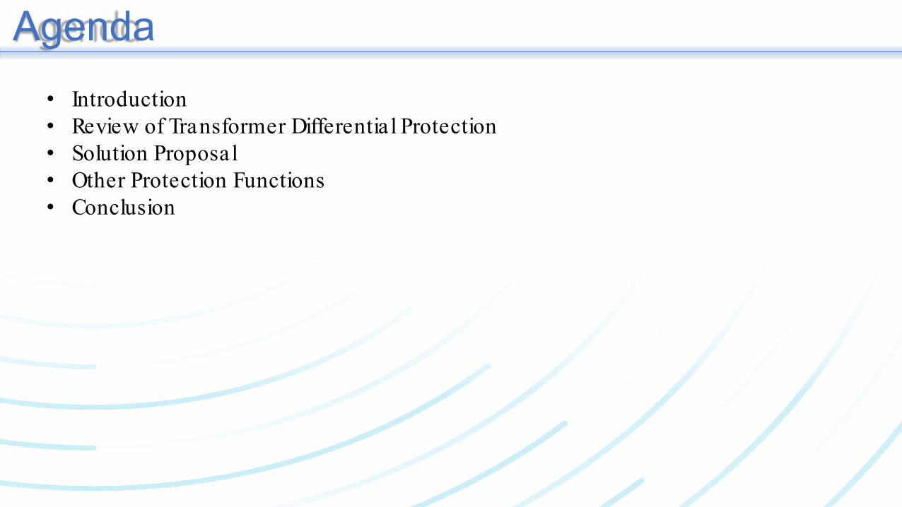
Agenda• Introduction• Review of Transformer Differentia l Protection• Solution Proposal• Other Protection Functions• Conclusion

IntroductionChurchill Falls Terminal Station 2 of theLower Churchill Project
Three new/extension sub:Muskrat FallsChurchill FallsSoldiers Pond
At Churchill Falls:3 Single-Phase Autotransformers3 x 280 MVA = 840 MVA735-315-13.8 kV

Review of Differential ProtectionKirchhoff's law“Teaching is the art of telling smaller and smaller lies”

Review of Differential ProtectionKirchhoff's law: Sum of Currents = Zero
Entering currents = Exiting currents
Asset Protected byDifferential Element
I 1 I 2
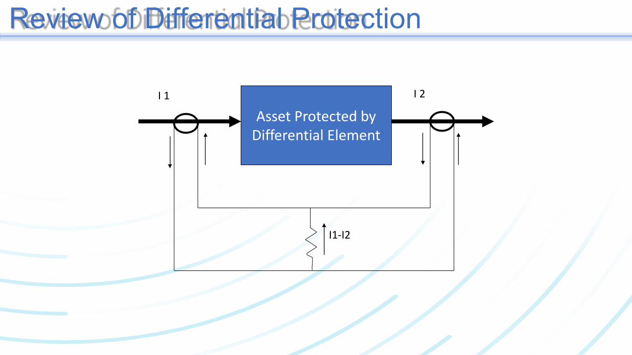
Review of Differential Protection
Asset Protected byDifferential Element
I 1 I 2
I1-I2

Review of Differential Protection
Asset Protected byDifferential Element
I 1 I 2
50/51

Review of Differential Protection
Asset Protected byDifferential Element
I 1 I 2
87

Review of Differential ProtectionBus Differentia lLine Differentia l
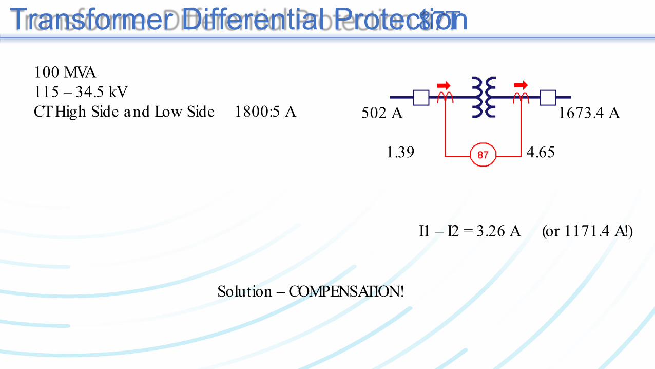
Transformer Differential Protection 87T
100 MVA115 – 34.5 kVCT High Side and Low Side 1800:5 A 502 A 1673.4 A
1.39 4.65
I1 – I2 = 3.26 A (or 1171.4 A!)
Solution – COMPENSATION!
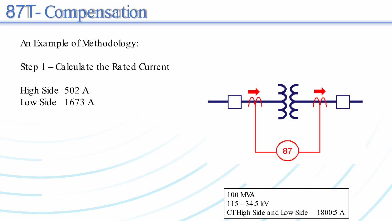
87T - CompensationAn Example of Methodology:
Step 1 – Calculate the Rated Current
High Side 502 ALow Side 1673 A
100 MVA115 – 34.5 kVCT High Side and Low Side 1800:5 A
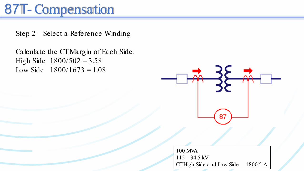
87T - CompensationStep 2 – Select a Reference Winding
Calculate the CT Margin of Each Side:High Side 1800/502 = 3.58Low Side 1800/1673 = 1.08
100 MVA115 – 34.5 kVCT High Side and Low Side 1800:5 A

Transformer Differential Protection 87T
Step 3 – Calculate the Magnitude Compensation
High Side I winding x V winding = 1800 x 115 = 3.33I ref x V ref 1800 x 34.5
Low Side =1.0
100 MVA115 – 34.5 kVCT High Side and Low Side 1800:5 A

87T - CompensationStep 4 – Apply the Compensation
I compensated = K winding x I measured
Example:Load 50 MVACurrent High Side: 251 ACurrent Low Side: 836.7 A
Compensated High Side: 3.33 x 251 = 835.8Compensated Low Side: 1.00 x 836.7 = 836.7
I1 – I2 ~ 0 A 100 MVA115 – 34.5 kVCT High Side and Low Side 1800:5 A

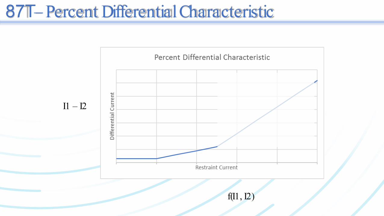
87T – Percent Differential Characteristic
I1 – I2
f(I1, I2)
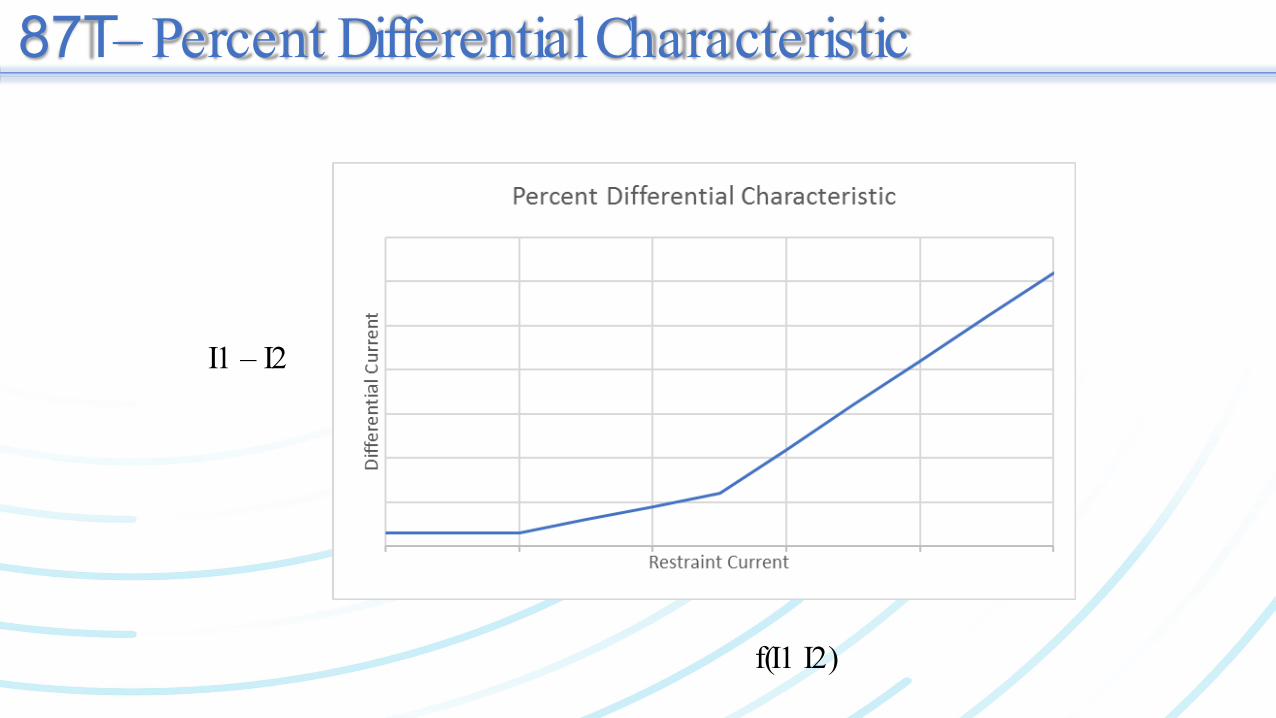
87T – Percent Differential Characteristic
I1 – I2
f(I1, I2)
87T – Percent Differential Characteristic
I1 – I2
f(I1 I2)

87T – Percent Differential Characteristic
Compensated High Side: 3.33 x 251 = 835.8Compensated Low Side: 1.00 x 836.7 = 836.7
I1 – I2 ~ 0 A I1 – I2 > Dynamic Threshold
I1 – I2
f(I1, I2)
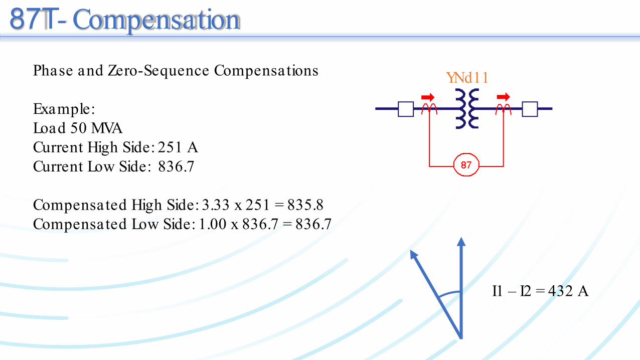
87T - CompensationPhase and Zero-Sequence Compensations
Example:Load 50 MVACurrent High Side: 251 ACurrent Low Side: 836.7
Compensated High Side: 3.33 x 251 = 835.8Compensated Low Side: 1.00 x 836.7 = 836.7
YNd11
I1 – I2 = 432 A

Transformer Differential Protection 87T
• The compensation method shown above is only one case.• There are different methods leading to different compensation factors.• Examples:

Churchill Falls Terminal Station 2• 840 MVA (3 x 280)• 735 kV / 315 kV / 13.8 kV• YNa0-D11
Single Phase Autotransformer T1, 3x280MVA
735 kVA B C
A B C A B C
13.8 kV315 kV
87T
Delta-Side CT inside the Delta

Churchill Falls Terminal Station 2• Detailed Transformer Parameters
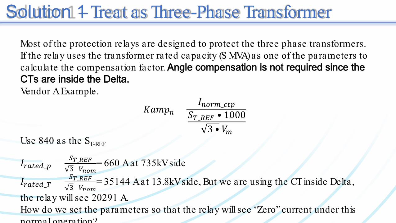
Solution 1 – Treat as Three-Phase TransformerMost of the protection relays are designed to protect the three phase transformers. If the relay uses the transformer ra ted capacity (S MVA) as one of the parameters to calculate the compensation factor. Angle compensation is not required since the CTs are inside the Delta.Vendor A Example.
𝐾𝐾𝐾𝐾𝐾𝐾𝐾𝐾𝑛𝑛 =𝐼𝐼𝑛𝑛𝑛𝑛𝑛𝑛𝑛𝑛_𝑐𝑐𝑐𝑐𝑐𝑐
𝑆𝑆𝑇𝑇_𝑅𝑅𝑅𝑅𝑅𝑅 • 10003 • 𝑉𝑉𝑛𝑛
Use 840 as the ST-REF
𝐼𝐼𝑛𝑛𝑟𝑟𝑐𝑐𝑟𝑟𝑟𝑟_𝑐𝑐 = 𝑆𝑆𝑇𝑇_𝑅𝑅𝑅𝑅𝑅𝑅3×𝑉𝑉𝑛𝑛𝑛𝑛𝑛𝑛
= 660 A at 735kV side
𝐼𝐼𝑛𝑛𝑟𝑟𝑐𝑐𝑟𝑟𝑟𝑟_𝑇𝑇 = 𝑆𝑆𝑇𝑇_𝑅𝑅𝑅𝑅𝑅𝑅3×𝑉𝑉𝑛𝑛𝑛𝑛𝑛𝑛
= 35144 A at 13.8kV side, But we are using the CT inside Delta , the relay will see 20291 A.How do we set the parameters so that the relay will see “Zero” current under this normal operation?

Solution 1 – Treat as Three-Phase TransformerSo the ra ted voltage on the Tertiary side has to be set “13.8x√3”, which is tricky since the ra ted voltage is 13.8 kV. Then the relay calculated compensation factor will be:
𝐾𝐾𝐾𝐾𝐾𝐾𝐾𝐾𝐻𝐻𝑉𝑉 = 3.031
𝐾𝐾𝐾𝐾𝐾𝐾𝐾𝐾𝑇𝑇𝑉𝑉 = 0.099
Now𝐼𝐼𝑛𝑛𝑟𝑟𝑐𝑐𝑟𝑟𝑟𝑟_𝑐𝑐*KampHV=660*3.031=2000.46𝐼𝐼𝑛𝑛𝑟𝑟𝑐𝑐𝑟𝑟𝑟𝑟_𝑇𝑇*KampTV=20291*3.031=2008.8
The relay will see zero differentia l current under normal load conditions.

Solution 2 – Treat as Single-Phase Transformer
Again, the relay will see “Zero” differential current under this normal operation condition!
𝐼𝐼𝑛𝑛𝑟𝑟𝑐𝑐𝑟𝑟𝑟𝑟_𝑐𝑐 =𝑆𝑆𝑇𝑇_𝑅𝑅𝑅𝑅𝑅𝑅𝑉𝑉𝑛𝑛𝑛𝑛𝑛𝑛
= 660A at 735kV side
𝐼𝐼𝑛𝑛𝑟𝑟𝑐𝑐𝑟𝑟𝑟𝑟_𝑇𝑇 =𝑆𝑆𝑇𝑇_𝑅𝑅𝑅𝑅𝑅𝑅𝑉𝑉𝑛𝑛𝑛𝑛𝑛𝑛
= 20289A at 13.8kV side
𝐾𝐾𝐾𝐾𝐾𝐾𝐾𝐾𝐻𝐻𝑉𝑉 = 5.242𝐾𝐾𝐾𝐾𝐾𝐾𝐾𝐾𝑇𝑇𝑉𝑉 = 0.171
Now𝐼𝐼𝑛𝑛𝑟𝑟𝑐𝑐𝑟𝑟𝑟𝑟_𝑐𝑐*KampHV = 660*5.242 = 3459.72 A𝐼𝐼𝑛𝑛𝑟𝑟𝑐𝑐𝑟𝑟𝑟𝑟_𝑇𝑇*KampTV = 20291*0.171 = 3469.76 A
Set the relay as ST-REF=280 MVA; VHV=424.4 kV, VLV=181.9 kV, VTV=13.8 kV

Restricted Earth Fault (REF)• Transformer Differentia l is often blind to faults near the neutral point .• REF is a differentia l protection function (I1-I2)
• I1 = Ia + Ib + Ic• I2 = Iground
Igd, pu
I = max(Ia,Ib,Ic), pu
Min. PKP
S lope
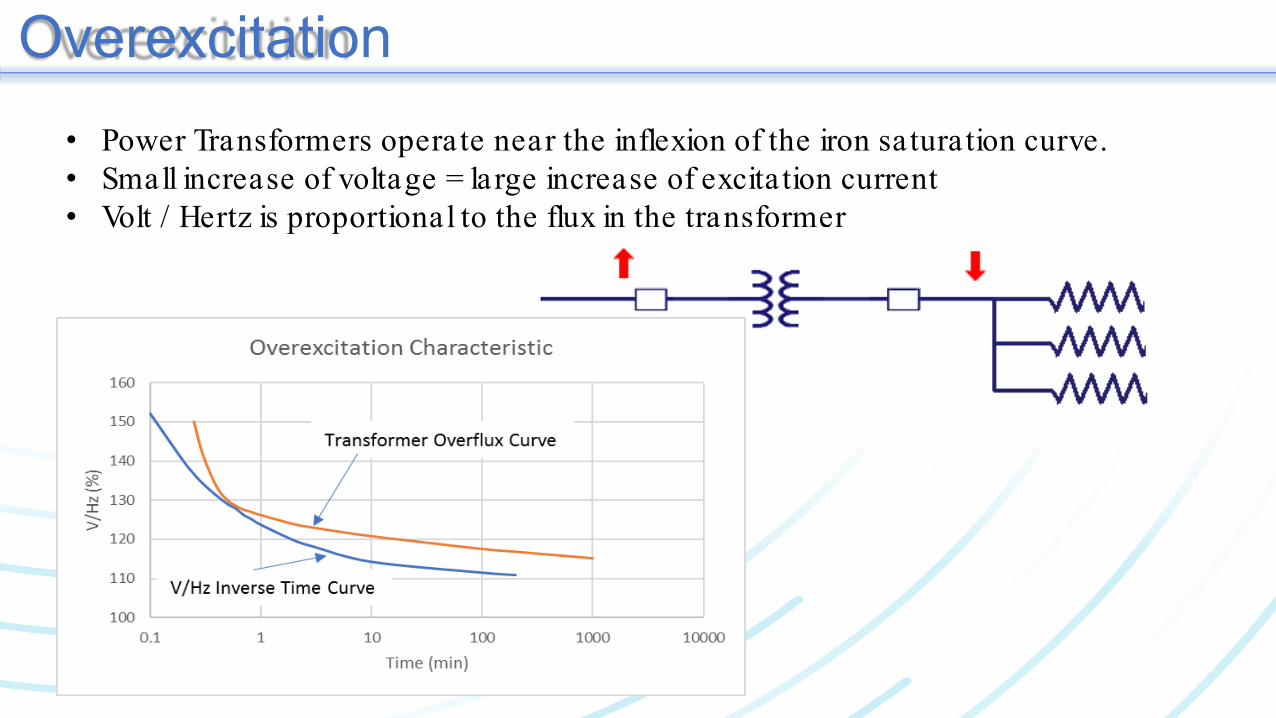
Overexcitation• Power Transformers operate near the inflexion of the iron saturation curve.• Small increase of voltage = large increase of excita tion current• Volt / Hertz is proportional to the flux in the transformer
Conclusions• Know your relay manufacturer• Know your relay model• Know why and how to protect your three single-phase power transformer

Thank You
Questions?