
Busbar and Multipurpose Differential Protection and Control ...
40
Relion ® 611 series Busbar and Multipurpose Differential Protection and Control REB611 Product Guide
Transcript of Busbar and Multipurpose Differential Protection and Control ...
Relion® 611 series
Busbar and Multipurpose DifferentialProtection and ControlREB611Product Guide
Contents
1. Description..................................................................... 3
2. Standardized configuration.............................................3
3. Protection functions........................................................6
4. Application..................................................................... 6
5. Supported ABB solutions............................................... 8
6. Control........................................................................... 9
7. Measurement................................................................. 9
8. Disturbance recorder......................................................9
9. Event log...................................................................... 10
10. Recorded data............................................................ 10
11. Trip circuit supervision ................................................10
12. Self-supervision...........................................................10
13. Access control............................................................ 10
14. Inputs and outputs...................................................... 10
15. Station communication................................................11
16. Technical data.............................................................16
17. Local HMI....................................................................28
18. Mounting methods...................................................... 28
19. Relay case and plug-in unit......................................... 29
20. Selection and ordering data.........................................30
21. Accessories and ordering data.................................... 31
22. Tools...........................................................................31
23. Cyber security............................................................. 32
24. Terminal diagram.........................................................33
25. Certificates.................................................................. 33
26. References..................................................................33
27. Functions, codes and symbols.................................... 34
28. Document revision history........................................... 35
Disclaimer
The information in this document is subject to change without notice and should not be construed as a commitment by ABB. ABB assumes no responsibility for any errors
that may appear in this document.
© Copyright 2016 ABB.
All rights reserved.
Trademarks
ABB and Relion are registered trademarks of the ABB Group. All other brand or product names mentioned in this document may be trademarks or registered trademarks
of their respective holders.
Busbar and Multipurpose Differential Protection and Control 1MRS757467 EREB611 Product version: 2.0
2 ABB
1. DescriptionREB611 is a dedicated busbar protection relay for phase-segregated short-circuit protection, control, and supervision ofsingle busbars. REB611 is intended for use in high-impedance-based applications within utility substations and industrialpower systems. In addition, the protection relay can be utilizedin restricted earth-fault and residual earth-fault applications forthe protection of generators, motors, transformers andreactors.
REB611 is a member of ABB’s Relion® product family and partof the 611 protection and control product series. The 611 seriesrelays are characterized by their compactness andwithdrawable-unit design.
The 611 series offers simplified yet powerful functionality formost applications. Once the application-specific parameter sethas been entered, the installed protection relay is ready to beput into service. The further addition of communicationfunctionality and interoperability between substationautomation devices offered by the IEC 61850 standard addsflexibility and value to end users as well as electrical systemmanufacturers.
The 611 series relays fully support the IEC 61850 standard forcommunication and interoperability of substation automationdevices, including fast GOOSE (Generic Object OrientedSubstation Event) messaging, and can now also benefit fromthe extended interoperability provided by Edition 2 of thestandard. The relays further support the parallel redundancyprotocol (PRP) and the high-availability seamless redundancy(HSR) protocol. The 611 series relays are able to use IEC 61850and Modbus® communication protocols simultaneously.
2. Standardized configurationREB611 is available in one configuration.
To increase the user-friendliness of the configuration and toemphasize the relay's simplicity of usage, only the application-specific parameters need setting within the relay's intendedarea of application.
The standard signal configuration can be altered by local HMI,Web HMI or optional application functionality of Protection andControl IED Manager PCM600.
Busbar and Multipurpose Differential Protection and Control 1MRS757467 EREB611 Product version: 2.0 Issued: 2016-02-22
Revision: E
ABB 3
3I>/Io>BF51BF/51NBF
Io>51N-1
Io>>51N-2
REMARKS
Optionalfunction
No. ofinstances
Alternative function to be defined when ordering
OR3×
Io/Uo
Calculatedvalue
CONDITION MONITORING AND SUPERVISION
CONTROL AND INDICATION 1) MEASUREMENT
- 3I, Io- Limit value supervision- Symmetrical components
BUSBAR AND MULTIPURPOSE DIFFERENTIAL PROTECTION RELAY STANDARD CONFIGURATION
LOCAL HMI
A
COMMUNICATION
Protocols: IEC 61850-8-1 Modbus®
Interfaces: Ethernet: TX (RJ-45), FX (LC) Serial: RS-485
Redundant protocols: HSR PRP RSTP
4
-
Analog interface types 1)
Current transformer
Voltage transformer1) Conventional transformer inputs
Object Ctrl 2) Ind 3)
CB
DC
ES
1 -
- -
- -1) Check availability of binary inputs/outputs from technical documentation2) Control and indication function for primary object3) Status indication function for primary object
PROTECTION
3I
ALSO AVAILABLE
- Disturbance and fault recorders- Event log and recorded data- Local/Remote push button on LHMI- Self-supervision- Time synchronization: IEEE 1588 v2, SNTP, IRIG-B- User management- Web-HMI
TCSTCM
2×
Io
REB611
MCS 1IMCS 1I
Master TripLockout relay
94/86
2×
3×dHi>87
3I
3×
RL
ESCI
O
AControlEventsMeasurementsDisturbance records
∆3I
GUID-57FB15B3-447A-4D9D-B342-C01EDA83D3F0 V1 EN
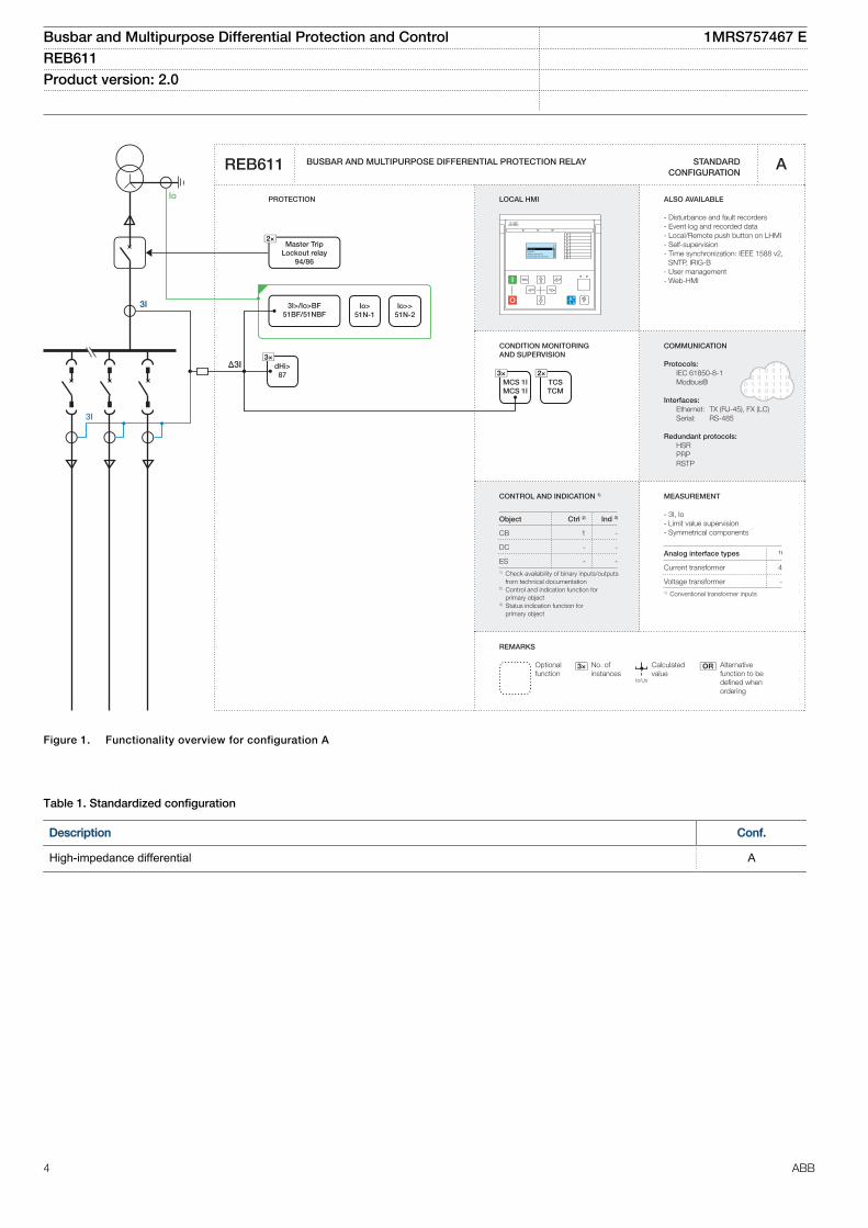
Figure 1. Functionality overview for configuration A
Table 1. Standardized configuration
Description Conf.
High-impedance differential A
Busbar and Multipurpose Differential Protection and Control 1MRS757467 EREB611 Product version: 2.0
4 ABB
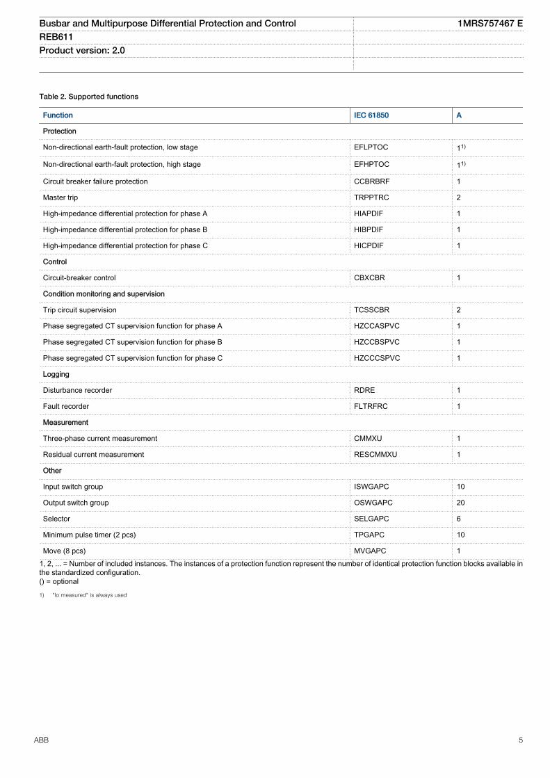
Table 2. Supported functions
Function IEC 61850 A
Protection
Non-directional earth-fault protection, low stage EFLPTOC 11)
Non-directional earth-fault protection, high stage EFHPTOC 11)
Circuit breaker failure protection CCBRBRF 1
Master trip TRPPTRC 2
High-impedance differential protection for phase A HIAPDIF 1
High-impedance differential protection for phase B HIBPDIF 1
High-impedance differential protection for phase C HICPDIF 1
Control
Circuit-breaker control CBXCBR 1
Condition monitoring and supervision
Trip circuit supervision TCSSCBR 2
Phase segregated CT supervision function for phase A HZCCASPVC 1
Phase segregated CT supervision function for phase B HZCCBSPVC 1
Phase segregated CT supervision function for phase C HZCCCSPVC 1
Logging
Disturbance recorder RDRE 1
Fault recorder FLTRFRC 1
Measurement
Three-phase current measurement CMMXU 1
Residual current measurement RESCMMXU 1
Other
Input switch group ISWGAPC 10
Output switch group OSWGAPC 20
Selector SELGAPC 6
Minimum pulse timer (2 pcs) TPGAPC 10
Move (8 pcs) MVGAPC 11, 2, ... = Number of included instances. The instances of a protection function represent the number of identical protection function blocks available inthe standardized configuration.() = optional
1) "Io measured" is always used
Busbar and Multipurpose Differential Protection and Control 1MRS757467 EREB611 Product version: 2.0
ABB 5
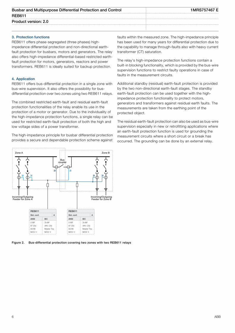
3. Protection functionsREB611 offers phase-segregated (three phases) high-impedance differential protection and non-directional earth-fault protection for busbars, motors and generators. The relayalso offers high-impedance differential-based restricted earth-fault protection for motors, generators, reactors and powertransformers. REB611 is ideally suited for backup protection.
4. ApplicationREB611 offers bus-differential protection in a single zone withbus-wire supervision. It also offers the possibility for bus-differential protection over two zones using two REB611 relays.
The combined restricted earth-fault and residual earth-faultprotection functionalities of the relay enable its use in theprotection of a motor or generator. Due to the individuality ofthe high-impedance protection functions, a single relay can beused for restricted earth-fault protection of both the high andlow voltage sides of a power transformer.
The high-impedance principle for busbar differential protectionprovides a secure and dependable protection scheme against
faults within the measured zone. The high-impedance principlehas been used for many years for differential protection due tothe capability to manage through-faults also with heavy currenttransformer (CT) saturation.
The relay's high-impedance protection functions contain abuilt-in blocking functionality, which is provided by the bus-wiresupervision functions to restrict faulty operations in case offaults in the measurement circuits.
Additional standby (residual) earth-fault protection is providedby the two non-directional earth-fault stages. The standbyearth-fault protection can be used together with the high-impedance protection functionality to protect motors,generators and transformers against residual earth faults. Themeasurements are taken from the earthing point of theprotected object.
The residual earth-fault protection can also be used as bus-wiresupervision especially in new or retrofitting applications wherean earth-fault protection function is used for grounding themeasurement circuits where a short circuit or a break hasoccurred. The grounding can be done by an external relay.
Zone A Zone B
3I3I
Incoming/OutgoingFeeder for Zone A
Incoming/OutgoingFeeder for Zone B
3I3I
Bus coupler
3I 3I
REB611
Std. conf.
ANSI IEC
51BF
87 (3x)
94/86
MCS 1I
3I>BF
dHi> (3x)
Master Trip
MCS 1I
A
REB611
Std. conf.
ANSI IEC
51BF
87 (3x)
94/86
MCS 1I
3I>BF
dHi> (3x)
Master Trip
MCS 1I
A
GUID-9D830E6D-F3C4-45D3-879E-FA6C6F140114 V2 EN
Figure 2. Bus-differential protection covering two zones with two REB611 relays
Busbar and Multipurpose Differential Protection and Control 1MRS757467 EREB611 Product version: 2.0
6 ABB
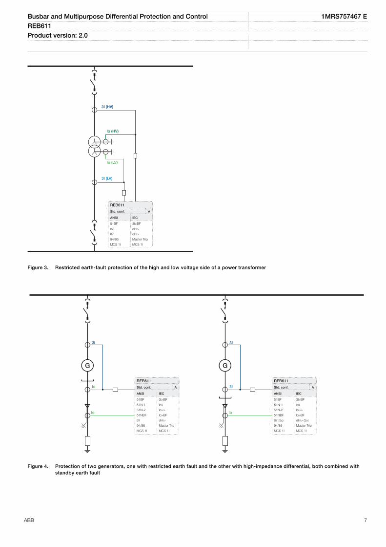
3I (HV)
Io (HV)
Io (LV)
3I (LV)
REB611
Std. conf.
ANSI IEC
51BF
87
87
94/86
MCS 1I
3I>BF
dHi>
dHi>
Master Trip
MCS 1I
A
GUID-9F68C879-2144-468C-9441-0BD7CB201E98 V2 EN
Figure 3. Restricted earth-fault protection of the high and low voltage side of a power transformer
REB611
Std. conf.
ANSI IEC
51BF
51N-1
51N-2
51NBF
87
94/86
MCS 1I
3I>BF
Io>
Io>>
Io>BF
dHi>
Master Trip
MCS 1I
AIo
G
Io
3I
3I
G
Io
3I
REB611
Std. conf.
ANSI IEC
51BF
51N-1
51N-2
51NBF
87 (3x)
94/86
MCS 1I
3I>BF
Io>
Io>>
Io>BF
dHi> (3x)
Master Trip
MCS 1I
A
GUID-55BADD92-9638-443A-9EB2-026DEA615AC3 V2 EN
Figure 4. Protection of two generators, one with restricted earth fault and the other with high-impedance differential, both combined withstandby earth fault
Busbar and Multipurpose Differential Protection and Control 1MRS757467 EREB611 Product version: 2.0
ABB 7
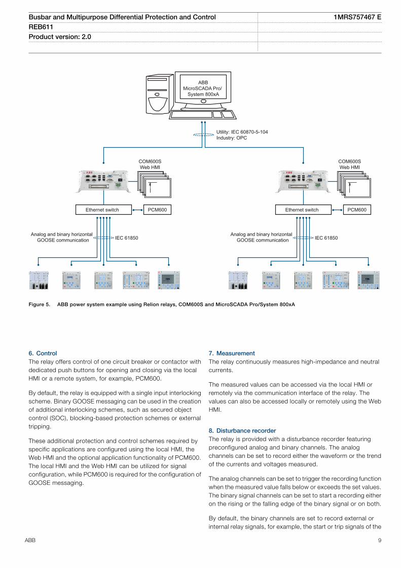
5. Supported ABB solutionsThe 611 series protection relays together with the SubstationManagement Unit COM600S constitute a genuine IEC 61850solution for reliable power distribution in utility and industrialpower systems. To facilitate the system engineering, ABB'srelays are supplied with connectivity packages. Theconnectivity packages include a compilation of software andrelay-specific information and a full relay data model. The datamodel includes event and parameter lists. With the connectivitypackages, the relays can be readily configured using PCM600and integrated with COM600S or the network control andmanagement system MicroSCADA Pro.
The 611 series relays offer native support for the IEC 61850standard, including limited binary GOOSE messaging.Compared to traditional hard-wired, inter-device signaling,peer-to-peer communication over a switched Ethernet LANoffers an advanced and versatile platform for power systemprotection. The implementation of the IEC 61850 substationautomation standard enables access to distinctive featuresincluding fast software-based communication, continuoussupervision of the protection and communication system'sintegrity, and inherent flexibility for reconfiguration andupgrades.
At substation level, COM600S uses the data content of the bay-level devices to enhance substation level functionality.
COM600S features a Web browser-based HMI, which providesa customizable graphical display for visualizing single-linemimic diagrams for switchgear bay solutions. The Web HMI ofCOM600S also provides an overview of the whole substation,including relay-specific single-line diagrams, which makesinformation easily accessible. Substation devices andprocesses can also be remotely accessed through the WebHMI, which improves personnel safety.
In addition, COM600S can be used as a local data warehousefor the substation's technical documentation and for thenetwork data collected by the devices. The collected networkdata facilitates extensive reporting and analyzing of networkfault situations by using the data historian and event handlingfeatures of COM600S. The historical data can be used foraccurate monitoring of process and equipment performance,using calculations based on both real-time and historicalvalues. A better understanding of the process dynamics isachieved by combining time-based process measurementswith production and maintenance events.
COM600S can also function as a gateway and provideseamless connectivity between the substation devices andnetwork-level control and management systems, such asMicroSCADA Pro and System 800xA.
Table 3. Supported ABB solutions
Product Version
Substation Management Unit COM600S 4.0 SP1 or later
4.1 or later (Edition 2)
MicroSCADA Pro SYS 600 9.3 FP2 or later
9.4 or later (Edition 2)
System 800xA 5.1 or later
Busbar and Multipurpose Differential Protection and Control 1MRS757467 EREB611 Product version: 2.0
8 ABB
PCM600Ethernet switch
Utility: IEC 60870-5-104Industry: OPC
COM600SWeb HMI
ABBMicroSCADA Pro/
System 800xA
Analog and binary horizontal GOOSE communication IEC 61850
PCM600Ethernet switch
COM600SWeb HMI
Analog and binary horizontal GOOSE communication IEC 61850
GUID-4D002AA0-E35D-4D3F-A157-01F1A3044DDB V3 EN
Figure 5. ABB power system example using Relion relays, COM600S and MicroSCADA Pro/System 800xA
6. ControlThe relay offers control of one circuit breaker or contactor withdedicated push buttons for opening and closing via the localHMI or a remote system, for example, PCM600.
By default, the relay is equipped with a single input interlockingscheme. Binary GOOSE messaging can be used in the creationof additional interlocking schemes, such as secured objectcontrol (SOC), blocking-based protection schemes or externaltripping.
These additional protection and control schemes required byspecific applications are configured using the local HMI, theWeb HMI and the optional application functionality of PCM600.The local HMI and the Web HMI can be utilized for signalconfiguration, while PCM600 is required for the configuration ofGOOSE messaging.
7. MeasurementThe relay continuously measures high-impedance and neutralcurrents.
The measured values can be accessed via the local HMI orremotely via the communication interface of the relay. Thevalues can also be accessed locally or remotely using the WebHMI.
8. Disturbance recorderThe relay is provided with a disturbance recorder featuringpreconfigured analog and binary channels. The analogchannels can be set to record either the waveform or the trendof the currents and voltages measured.
The analog channels can be set to trigger the recording functionwhen the measured value falls below or exceeds the set values.The binary signal channels can be set to start a recording eitheron the rising or the falling edge of the binary signal or on both.
By default, the binary channels are set to record external orinternal relay signals, for example, the start or trip signals of the
Busbar and Multipurpose Differential Protection and Control 1MRS757467 EREB611 Product version: 2.0
ABB 9
relay stages, or external blocking or control signals. Binary relaysignals, such as protection start and trip signals, or an externalrelay control signal via a binary input, can be set to trigger therecording. Recorded information is stored in a non-volatilememory and can be uploaded for subsequent fault analysis.
9. Event logTo collect sequence-of-events information, the relay has a non-volatile memory capable of storing 1024 events with theassociated time stamps. The non-volatile memory retains itsdata even if the relay temporarily loses its auxiliary supply. Theevent log facilitates detailed pre- and post-fault analyses offeeder faults and disturbances. The considerable capacity toprocess and store data and events in the relay facilitatesmeeting the growing information demand of future networkconfigurations.
The sequence-of-events information can be accessed either vialocal HMI or remotely via the communication interface of therelay. The information can also be accessed locally or remotelyusing the Web HMI.
10. Recorded dataThe relay has the capacity to store the records of the 128 latestfault events. The records can be used to analyze the powersystem events. Each record includes, for example, current,residual voltage and angle values, start times of the protectionblocks and a time stamp. The fault recording can be triggeredby the start or the trip signal of a protection block, or by both.The available measurement modes include DFT, RMS andpeak-to-peak. Fault records store relay measurement values atthe moment when any protection function starts. In addition,the maximum demand current with time stamp is separatelyrecorded. The records are stored in the non-volatile memory.
11. Trip circuit supervisionThe trip circuit supervision continuously monitors the availabilityand operation of the trip circuit. It provides two open-circuitmonitoring functions that can be used to monitor the circuitbreaker’s control signal circuits. It also detects loss of circuit-breaker control voltage.
The measurement circuit supervision function of the relayconstantly monitors the performance of the current
transformer. This is done with the phase-segregated CTsupervision function.
12. Self-supervisionThe relay’s built-in self-supervision system continuouslymonitors the state of the relay hardware and the operation ofthe relay software. Any fault or malfunction detected is used foralerting the operator.
A permanent relay fault blocks the protection functions toprevent incorrect operation.
13. Access controlTo protect the relay from unauthorized access and to maintaininformation integrity, the relay is provided with a four-level, role-based authentication system with administrator-programmableindividual passwords for the viewer, operator, engineer andadministrator levels. The access control applies to the localHMI, the Web HMI and PCM600.
14. Inputs and outputsThe relay is equipped with three phase-segregated differentialcurrent inputs and one residual current input. The differentialand the residual current inputs are rated 1/5 A, that is, theinputs can be connected to either 1 A or 5 A secondary currenttransformers. The optional residual current input rated 0.2/1 Ais normally used in applications requiring sensitive earth-faultprotection and featuring core-balance current transformers.
The rated currents of the analog inputs can be selected in therelay software. In addition, the binary input threshold (16…176V DC) can be selected by adjusting the relay’s parametersettings.
All binary input and output contacts are preconfiguredaccording to the configuration, but can be easily reconfiguredby setting application-based parameters using the signalconfiguration functionality of the local HMI and Web HMI.
See the input and output overview table and the terminaldiagram for more information about the inputs and outputs.
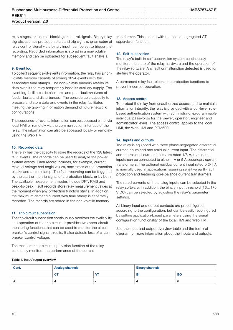
Table 4. Input/output overview
Conf. Analog channels Binary channels
CT VT BI BO
A 4 - 4 6
Busbar and Multipurpose Differential Protection and Control 1MRS757467 EREB611 Product version: 2.0
10 ABB
15. Station communicationThe 611 series protection relays support the IEC 61850 and
Modbus® communication protocols. Operational informationand controls are available through these protocols. However,some communication functionality, for example, horizontalcommunication between the protection relays, is enabled onlyby the IEC 61850 communication protocol.
The IEC 61850 protocol is a core part of the relay as theprotection and control application is fully based on standardmodelling. The relay supports Edition 1 and Edition 2 versionsof the standard. With Edition 2 support, the relay has the latestfunctionality modelling for substation applications and the bestinteroperability for modern substations. It incorporates also fullsupport for standard device mode functionality supportingdifferent test applications. Control applications can utilize thenew safe and advanced station control authority feature.
The IEC 61850 communication implementation supportsmonitoring and control functions. Additionally, parametersettings, disturbance recordings and fault records can beaccessed using the IEC 61850 protocol. Disturbancerecordings are available to any Ethernet-based application inthe standard COMTRADE file format. The relay supportssimultaneous event reporting to five different clients on thestation bus. The relay can exchange data with other devicesusing the IEC 61850 protocol.
The relay can send binary and analog signals to other devicesusing the IEC 61850-8-1 GOOSE (Generic Object OrientedSubstation Event) profile. Binary GOOSE messaging can beemployed, for example, for protection and interlocking-basedprotection schemes. The relay meets the GOOSE performance
requirements for tripping applications in distributionsubstations, as defined by the IEC 61850 standard (<10 msdata exchange between the devices).
For redundant Ethernet communication, the relay offers twogalvanic Ethernet network interfaces. A third port with galvanicEthernet network interface is also available providingconnectivity for any other Ethernet device to an IEC 61850station bus inside a switchgear bay, for example connection ofa remote I/O. Ethernet network redundancy can be achievedusing the high-availability seamless redundancy protocol (HSR)or the parallel redundancy protocol (PRP) or with a self-healingring using Rapid Spanning Tree Protocol (RSTP) in managedswitches. Ethernet redundancy can be applied to Ethernet-based IEC 61850 and Modbus protocols.
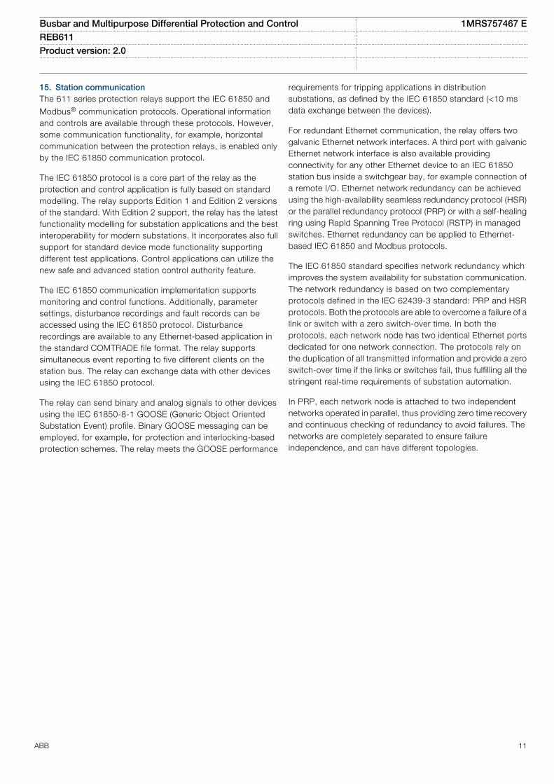
The IEC 61850 standard specifies network redundancy whichimproves the system availability for substation communication.The network redundancy is based on two complementaryprotocols defined in the IEC 62439-3 standard: PRP and HSRprotocols. Both the protocols are able to overcome a failure of alink or switch with a zero switch-over time. In both theprotocols, each network node has two identical Ethernet portsdedicated for one network connection. The protocols rely onthe duplication of all transmitted information and provide a zeroswitch-over time if the links or switches fail, thus fulfilling all thestringent real-time requirements of substation automation.
In PRP, each network node is attached to two independentnetworks operated in parallel, thus providing zero time recoveryand continuous checking of redundancy to avoid failures. Thenetworks are completely separated to ensure failureindependence, and can have different topologies.
Busbar and Multipurpose Differential Protection and Control 1MRS757467 EREB611 Product version: 2.0
ABB 11
Managed
Ethernet switchIEC 61850 PRP Managed
Ethernet switch
GUID-AA005F1B-A30B-48F6-84F4-A108F58615A2 V1 EN
Figure 6. Parallel redundancy protocol (PRP) solution
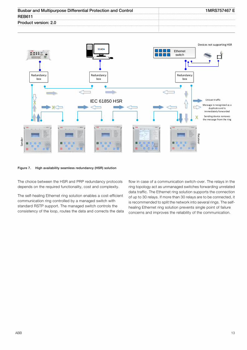
HSR applies the PRP principle of parallel operation to a singlering. For each message sent, the node sends two frames, onethrough each port. Both the frames circulate in oppositedirections over the ring. Every node forwards the frames itreceives from one port to another to reach the next node. Whenthe originating sender node receives the frame it sent, it
discards the frame to avoid loops. The HSR ring with the 611series relays supports the connection of up to 30 relays. If morethan 30 relays are to be connected, it is recommended to splitthe network into several rings to guarantee the performance forreal-time applications.
Busbar and Multipurpose Differential Protection and Control 1MRS757467 EREB611 Product version: 2.0
12 ABB
IEC 61850 HSR
Ethernet switch
Redundancy box
Redundancy box
Redundancy box
XX
Unicast traffic
Message is recognized as a duplicate and is
immediately forwarded
X Sending device removes the message from the ring
Devices not supporting HSR
Sen
der
Receiver
GUID-B24F8609-0E74-4318-8168-A6E7FCD0B313 V1 EN
Figure 7. High availability seamless redundancy (HSR) solution
The choice between the HSR and PRP redundancy protocolsdepends on the required functionality, cost and complexity.
The self-healing Ethernet ring solution enables a cost-efficientcommunication ring controlled by a managed switch withstandard RSTP support. The managed switch controls theconsistency of the loop, routes the data and corrects the data
flow in case of a communication switch-over. The relays in thering topology act as unmanaged switches forwarding unrelateddata traffic. The Ethernet ring solution supports the connectionof up to 30 relays. If more than 30 relays are to be connected, itis recommended to split the network into several rings. The self-healing Ethernet ring solution prevents single point of failureconcerns and improves the reliability of the communication.
Busbar and Multipurpose Differential Protection and Control 1MRS757467 EREB611 Product version: 2.0
ABB 13
Managed Ethernet switch
with RSTP support
Managed Ethernet switch
with RSTP support
Client A Client B
Network
Network
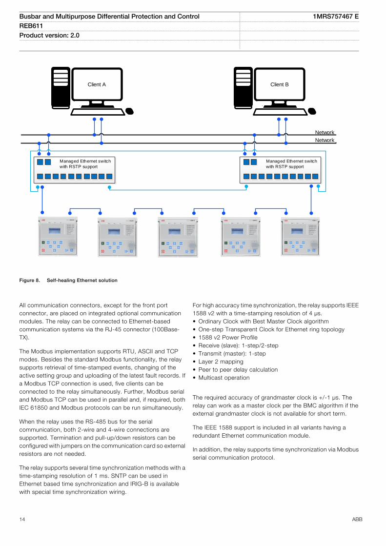
GUID-A19C6CFB-EEFD-4FB2-9671-E4C4137550A1 V2 EN
Figure 8. Self-healing Ethernet solution
All communication connectors, except for the front portconnector, are placed on integrated optional communicationmodules. The relay can be connected to Ethernet-basedcommunication systems via the RJ-45 connector (100Base-TX).
The Modbus implementation supports RTU, ASCII and TCPmodes. Besides the standard Modbus functionality, the relaysupports retrieval of time-stamped events, changing of theactive setting group and uploading of the latest fault records. Ifa Modbus TCP connection is used, five clients can beconnected to the relay simultaneously. Further, Modbus serialand Modbus TCP can be used in parallel and, if required, bothIEC 61850 and Modbus protocols can be run simultaneously.
When the relay uses the RS-485 bus for the serialcommunication, both 2-wire and 4-wire connections aresupported. Termination and pull-up/down resistors can beconfigured with jumpers on the communication card so externalresistors are not needed.
The relay supports several time synchronization methods with atime-stamping resolution of 1 ms. SNTP can be used inEthernet based time synchronization and IRIG-B is availablewith special time synchronization wiring.
For high accuracy time synchronization, the relay supports IEEE1588 v2 with a time-stamping resolution of 4 μs.• Ordinary Clock with Best Master Clock algorithm• One-step Transparent Clock for Ethernet ring topology• 1588 v2 Power Profile• Receive (slave): 1-step/2-step• Transmit (master): 1-step• Layer 2 mapping• Peer to peer delay calculation• Multicast operation
The required accuracy of grandmaster clock is +/-1 μs. Therelay can work as a master clock per the BMC algorithm if theexternal grandmaster clock is not available for short term.
The IEEE 1588 support is included in all variants having aredundant Ethernet communication module.
In addition, the relay supports time synchronization via Modbusserial communication protocol.
Busbar and Multipurpose Differential Protection and Control 1MRS757467 EREB611 Product version: 2.0
14 ABB
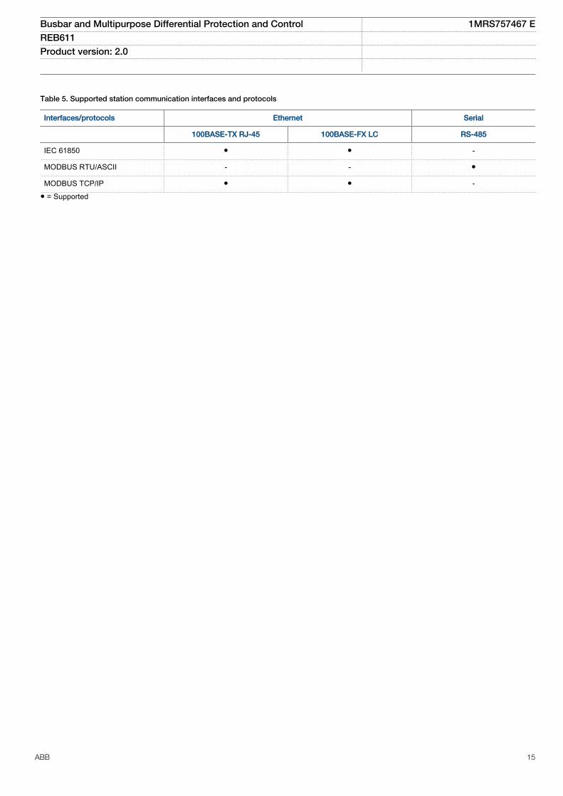
Table 5. Supported station communication interfaces and protocols
Interfaces/protocols Ethernet Serial
100BASE-TX RJ-45 100BASE-FX LC RS-485
IEC 61850 ● ● -
MODBUS RTU/ASCII - - ●
MODBUS TCP/IP ● ● -● = Supported
Busbar and Multipurpose Differential Protection and Control 1MRS757467 EREB611 Product version: 2.0
ABB 15
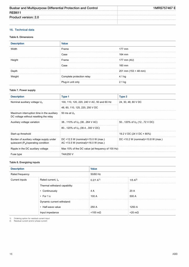
16. Technical data
Table 6. Dimensions
Description Value
Width Frame 177 mm
Case 164 mm
Height Frame 177 mm (4U)
Case 160 mm
Depth 201 mm (153 + 48 mm)
Weight Complete protection relay 4.1 kg
Plug-in unit only 2.1 kg
Table 7. Power supply
Description Type 1 Type 2
Nominal auxiliary voltage Un 100, 110, 120, 220, 240 V AC, 50 and 60 Hz 24, 30, 48, 60 V DC
48, 60, 110, 125, 220, 250 V DC
Maximum interruption time in the auxiliaryDC voltage without resetting the relay
50 ms at Un
Auxiliary voltage variation 38...110% of Un (38...264 V AC) 50...120% of Un (12...72 V DC)
80...120% of Un (38.4...300 V DC)
Start-up threshold 19.2 V DC (24 V DC × 80%)
Burden of auxiliary voltage supply underquiescent (Pq)/operating condition
DC <12.5 W (nominal)/<15.0 W (max.)AC <13.5 W (nominal)/<16.0 W (max.)
DC <10.2 W (nominal)/<10.8 W (max.)
Ripple in the DC auxiliary voltage Max 15% of the DC value (at frequency of 100 Hz)
Fuse type T4A/250 V
Table 8. Energizing inputs
Description Value
Rated frequency 50/60 Hz
Current inputs Rated current, In 0.2/1 A1) 1/5 A2)
Thermal withstand capability:
• Continuously 4 A 20 A
• For 1 s 100 A 500 A
Dynamic current withstand:
• Half-wave value 250 A 1250 A
Input impedance <100 mΩ <20 mΩ
1) Ordering option for residual current input2) Residual current and/or phase current
Busbar and Multipurpose Differential Protection and Control 1MRS757467 EREB611 Product version: 2.0
16 ABB
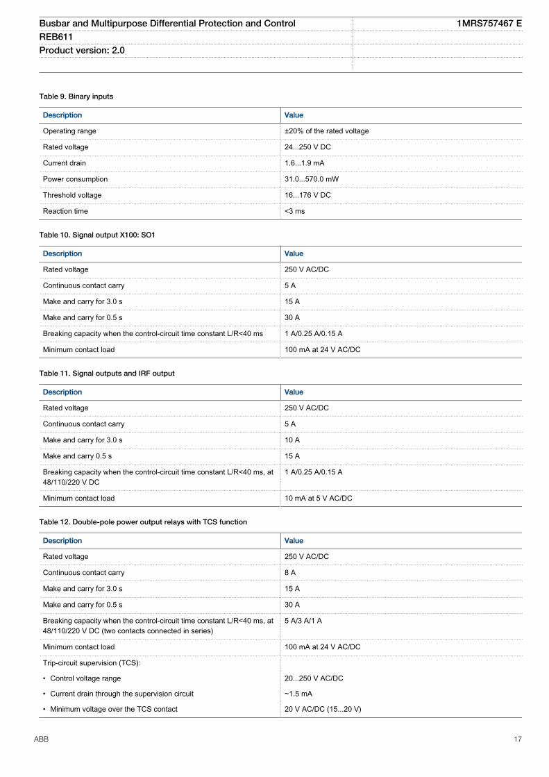
Table 9. Binary inputs
Description Value
Operating range ±20% of the rated voltage
Rated voltage 24...250 V DC
Current drain 1.6...1.9 mA
Power consumption 31.0...570.0 mW
Threshold voltage 16...176 V DC
Reaction time <3 ms
Table 10. Signal output X100: SO1
Description Value
Rated voltage 250 V AC/DC
Continuous contact carry 5 A
Make and carry for 3.0 s 15 A
Make and carry for 0.5 s 30 A
Breaking capacity when the control-circuit time constant L/R<40 ms 1 A/0.25 A/0.15 A
Minimum contact load 100 mA at 24 V AC/DC
Table 11. Signal outputs and IRF output
Description Value
Rated voltage 250 V AC/DC
Continuous contact carry 5 A
Make and carry for 3.0 s 10 A
Make and carry 0.5 s 15 A
Breaking capacity when the control-circuit time constant L/R<40 ms, at48/110/220 V DC
1 A/0.25 A/0.15 A
Minimum contact load 10 mA at 5 V AC/DC
Table 12. Double-pole power output relays with TCS function
Description Value
Rated voltage 250 V AC/DC
Continuous contact carry 8 A
Make and carry for 3.0 s 15 A
Make and carry for 0.5 s 30 A
Breaking capacity when the control-circuit time constant L/R<40 ms, at48/110/220 V DC (two contacts connected in series)
5 A/3 A/1 A
Minimum contact load 100 mA at 24 V AC/DC
Trip-circuit supervision (TCS):
• Control voltage range 20...250 V AC/DC
• Current drain through the supervision circuit ~1.5 mA
• Minimum voltage over the TCS contact 20 V AC/DC (15...20 V)
Busbar and Multipurpose Differential Protection and Control 1MRS757467 EREB611 Product version: 2.0
ABB 17
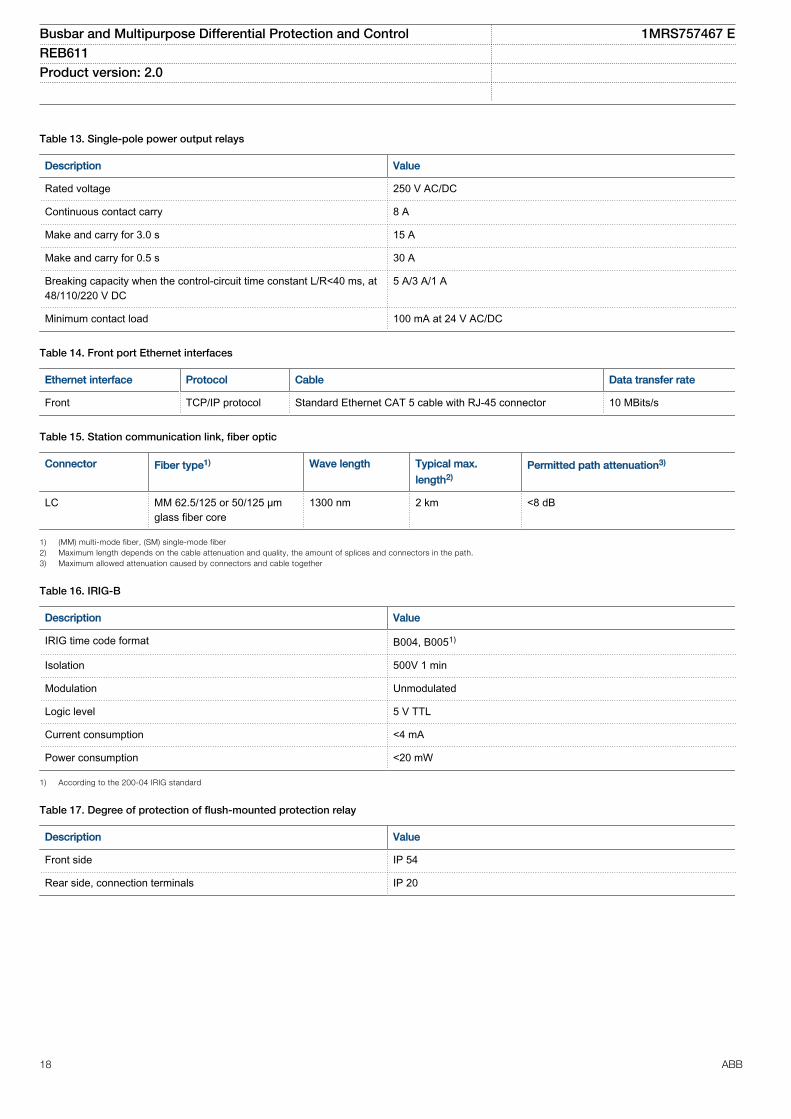
Table 13. Single-pole power output relays
Description Value
Rated voltage 250 V AC/DC
Continuous contact carry 8 A
Make and carry for 3.0 s 15 A
Make and carry for 0.5 s 30 A
Breaking capacity when the control-circuit time constant L/R<40 ms, at48/110/220 V DC
5 A/3 A/1 A
Minimum contact load 100 mA at 24 V AC/DC
Table 14. Front port Ethernet interfaces
Ethernet interface Protocol Cable Data transfer rate
Front TCP/IP protocol Standard Ethernet CAT 5 cable with RJ-45 connector 10 MBits/s
Table 15. Station communication link, fiber optic
Connector Fiber type1) Wave length Typical max.
length2)Permitted path attenuation3)
LC MM 62.5/125 or 50/125 μmglass fiber core
1300 nm 2 km <8 dB
1) (MM) multi-mode fiber, (SM) single-mode fiber2) Maximum length depends on the cable attenuation and quality, the amount of splices and connectors in the path.3) Maximum allowed attenuation caused by connectors and cable together
Table 16. IRIG-B
Description Value
IRIG time code format B004, B0051)
Isolation 500V 1 min
Modulation Unmodulated
Logic level 5 V TTL
Current consumption <4 mA
Power consumption <20 mW
1) According to the 200-04 IRIG standard
Table 17. Degree of protection of flush-mounted protection relay
Description Value
Front side IP 54
Rear side, connection terminals IP 20
Busbar and Multipurpose Differential Protection and Control 1MRS757467 EREB611 Product version: 2.0
18 ABB
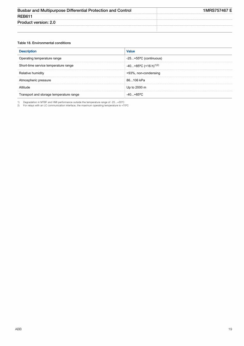
Table 18. Environmental conditions
Description Value
Operating temperature range -25...+55ºC (continuous)
Short-time service temperature range -40...+85ºC (<16 h)1)2)
Relative humidity <93%, non-condensing
Atmospheric pressure 86...106 kPa
Altitude Up to 2000 m
Transport and storage temperature range -40...+85ºC
1) Degradation in MTBF and HMI performance outside the temperature range of -25...+55ºC2) For relays with an LC communication interface, the maximum operating temperature is +70ºC
Busbar and Multipurpose Differential Protection and Control 1MRS757467 EREB611 Product version: 2.0
ABB 19
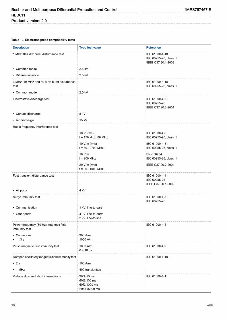
Table 19. Electromagnetic compatibility tests
Description Type test value Reference
1 MHz/100 kHz burst disturbance test IEC 61000-4-18IEC 60255-26, class IIIIEEE C37.90.1-2002
• Common mode 2.5 kV
• Differential mode 2.5 kV
3 MHz, 10 MHz and 30 MHz burst disturbancetest
IEC 61000-4-18IEC 60255-26, class III
• Common mode 2.5 kV
Electrostatic discharge test IEC 61000-4-2IEC 60255-26IEEE C37.90.3-2001
• Contact discharge 8 kV
• Air discharge 15 kV
Radio frequency interference test
10 V (rms)f = 150 kHz...80 MHz
IEC 61000-4-6IEC 60255-26, class III
10 V/m (rms)f = 80...2700 MHz
IEC 61000-4-3IEC 60255-26, class III
10 V/mf = 900 MHz
ENV 50204IEC 60255-26, class III
20 V/m (rms)f = 80...1000 MHz
IEEE C37.90.2-2004
Fast transient disturbance test IEC 61000-4-4IEC 60255-26IEEE C37.90.1-2002
• All ports 4 kV
Surge immunity test IEC 61000-4-5IEC 60255-26
• Communication 1 kV, line-to-earth
• Other ports 4 kV, line-to-earth2 kV, line-to-line
Power frequency (50 Hz) magnetic fieldimmunity test
IEC 61000-4-8
• Continuous• 1...3 s
300 A/m1000 A/m
Pulse magnetic field immunity test 1000 A/m6.4/16 µs
IEC 61000-4-9
Damped oscillatory magnetic field immunity test IEC 61000-4-10
• 2 s 100 A/m
• 1 MHz 400 transients/s
Voltage dips and short interruptions 30%/10 ms60%/100 ms60%/1000 ms>95%/5000 ms
IEC 61000-4-11
Busbar and Multipurpose Differential Protection and Control 1MRS757467 EREB611 Product version: 2.0
20 ABB
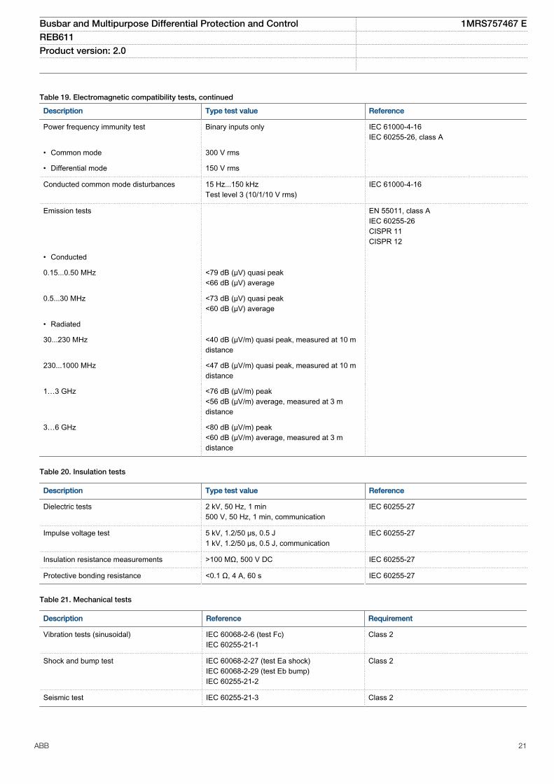
Table 19. Electromagnetic compatibility tests, continued
Description Type test value Reference
Power frequency immunity test Binary inputs only IEC 61000-4-16IEC 60255-26, class A
• Common mode 300 V rms
• Differential mode 150 V rms
Conducted common mode disturbances 15 Hz...150 kHzTest level 3 (10/1/10 V rms)
IEC 61000-4-16
Emission tests EN 55011, class AIEC 60255-26CISPR 11CISPR 12
• Conducted
0.15...0.50 MHz <79 dB (µV) quasi peak<66 dB (µV) average
0.5...30 MHz <73 dB (µV) quasi peak<60 dB (µV) average
• Radiated
30...230 MHz <40 dB (µV/m) quasi peak, measured at 10 mdistance
230...1000 MHz <47 dB (µV/m) quasi peak, measured at 10 mdistance
1…3 GHz <76 dB (µV/m) peak<56 dB (µV/m) average, measured at 3 mdistance
3…6 GHz <80 dB (µV/m) peak<60 dB (µV/m) average, measured at 3 mdistance
Table 20. Insulation tests
Description Type test value Reference
Dielectric tests 2 kV, 50 Hz, 1 min500 V, 50 Hz, 1 min, communication
IEC 60255-27
Impulse voltage test 5 kV, 1.2/50 μs, 0.5 J1 kV, 1.2/50 μs, 0.5 J, communication
IEC 60255-27
Insulation resistance measurements >100 MΩ, 500 V DC IEC 60255-27
Protective bonding resistance <0.1 Ω, 4 A, 60 s IEC 60255-27
Table 21. Mechanical tests
Description Reference Requirement
Vibration tests (sinusoidal) IEC 60068-2-6 (test Fc)IEC 60255-21-1
Class 2
Shock and bump test IEC 60068-2-27 (test Ea shock)IEC 60068-2-29 (test Eb bump)IEC 60255-21-2
Class 2
Seismic test IEC 60255-21-3 Class 2
Busbar and Multipurpose Differential Protection and Control 1MRS757467 EREB611 Product version: 2.0
ABB 21
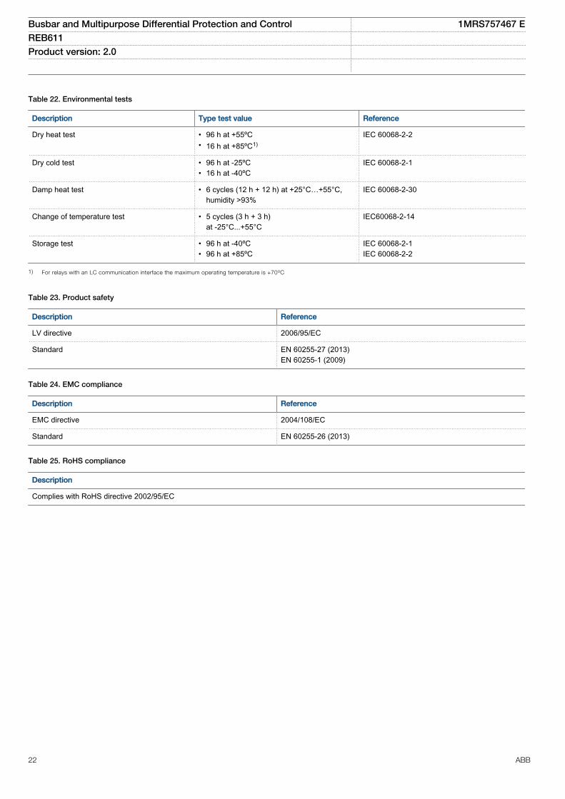
Table 22. Environmental tests
Description Type test value Reference
Dry heat test • 96 h at +55ºC• 16 h at +85ºC1)
IEC 60068-2-2
Dry cold test • 96 h at -25ºC• 16 h at -40ºC
IEC 60068-2-1
Damp heat test • 6 cycles (12 h + 12 h) at +25°C…+55°C,humidity >93%
IEC 60068-2-30
Change of temperature test • 5 cycles (3 h + 3 h)at -25°C...+55°C
IEC60068-2-14
Storage test • 96 h at -40ºC• 96 h at +85ºC
IEC 60068-2-1IEC 60068-2-2
1) For relays with an LC communication interface the maximum operating temperature is +70oC
Table 23. Product safety
Description Reference
LV directive 2006/95/EC
Standard EN 60255-27 (2013)EN 60255-1 (2009)
Table 24. EMC compliance
Description Reference
EMC directive 2004/108/EC
Standard EN 60255-26 (2013)
Table 25. RoHS compliance
Description
Complies with RoHS directive 2002/95/EC
Busbar and Multipurpose Differential Protection and Control 1MRS757467 EREB611 Product version: 2.0
22 ABB
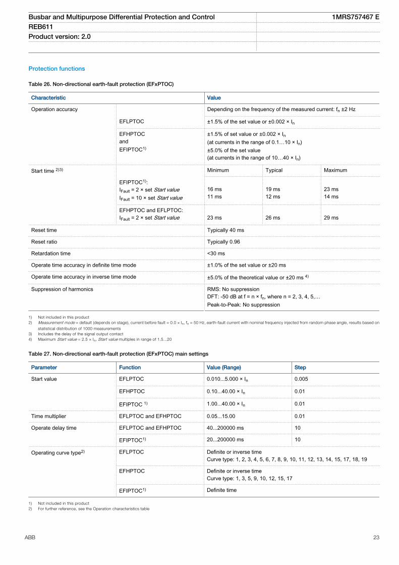
Protection functions
Table 26. Non-directional earth-fault protection (EFxPTOC)
Characteristic Value
Operation accuracy Depending on the frequency of the measured current: fn ±2 Hz
EFLPTOC ±1.5% of the set value or ±0.002 × In
EFHPTOCandEFIPTOC1)
±1.5% of set value or ±0.002 × In(at currents in the range of 0.1…10 × In)±5.0% of the set value(at currents in the range of 10…40 × In)
Start time 2)3) Minimum Typical Maximum
EFIPTOC1):IFault = 2 × set Start valueIFault = 10 × set Start value
16 ms11 ms
19 ms12 ms
23 ms14 ms
EFHPTOC and EFLPTOC:IFault = 2 × set Start value
23 ms
26 ms
29 ms
Reset time Typically 40 ms
Reset ratio Typically 0.96
Retardation time <30 ms
Operate time accuracy in definite time mode ±1.0% of the set value or ±20 ms
Operate time accuracy in inverse time mode ±5.0% of the theoretical value or ±20 ms 4)
Suppression of harmonics RMS: No suppressionDFT: -50 dB at f = n × fn, where n = 2, 3, 4, 5,…Peak-to-Peak: No suppression
1) Not included in this product2) Measurement mode = default (depends on stage), current before fault = 0.0 × In, fn = 50 Hz, earth-fault current with nominal frequency injected from random phase angle, results based on
statistical distribution of 1000 measurements3) Includes the delay of the signal output contact4) Maximum Start value = 2.5 × In, Start value multiples in range of 1.5...20
Table 27. Non-directional earth-fault protection (EFxPTOC) main settings
Parameter Function Value (Range) Step
Start value EFLPTOC 0.010...5.000 × In 0.005
EFHPTOC 0.10...40.00 × In 0.01
EFIPTOC 1) 1.00...40.00 × In 0.01
Time multiplier EFLPTOC and EFHPTOC 0.05...15.00 0.01
Operate delay time EFLPTOC and EFHPTOC 40...200000 ms 10
EFIPTOC1) 20...200000 ms 10
Operating curve type2) EFLPTOC Definite or inverse timeCurve type: 1, 2, 3, 4, 5, 6, 7, 8, 9, 10, 11, 12, 13, 14, 15, 17, 18, 19
EFHPTOC Definite or inverse timeCurve type: 1, 3, 5, 9, 10, 12, 15, 17
EFIPTOC1) Definite time
1) Not included in this product2) For further reference, see the Operation characteristics table
Busbar and Multipurpose Differential Protection and Control 1MRS757467 EREB611 Product version: 2.0
ABB 23
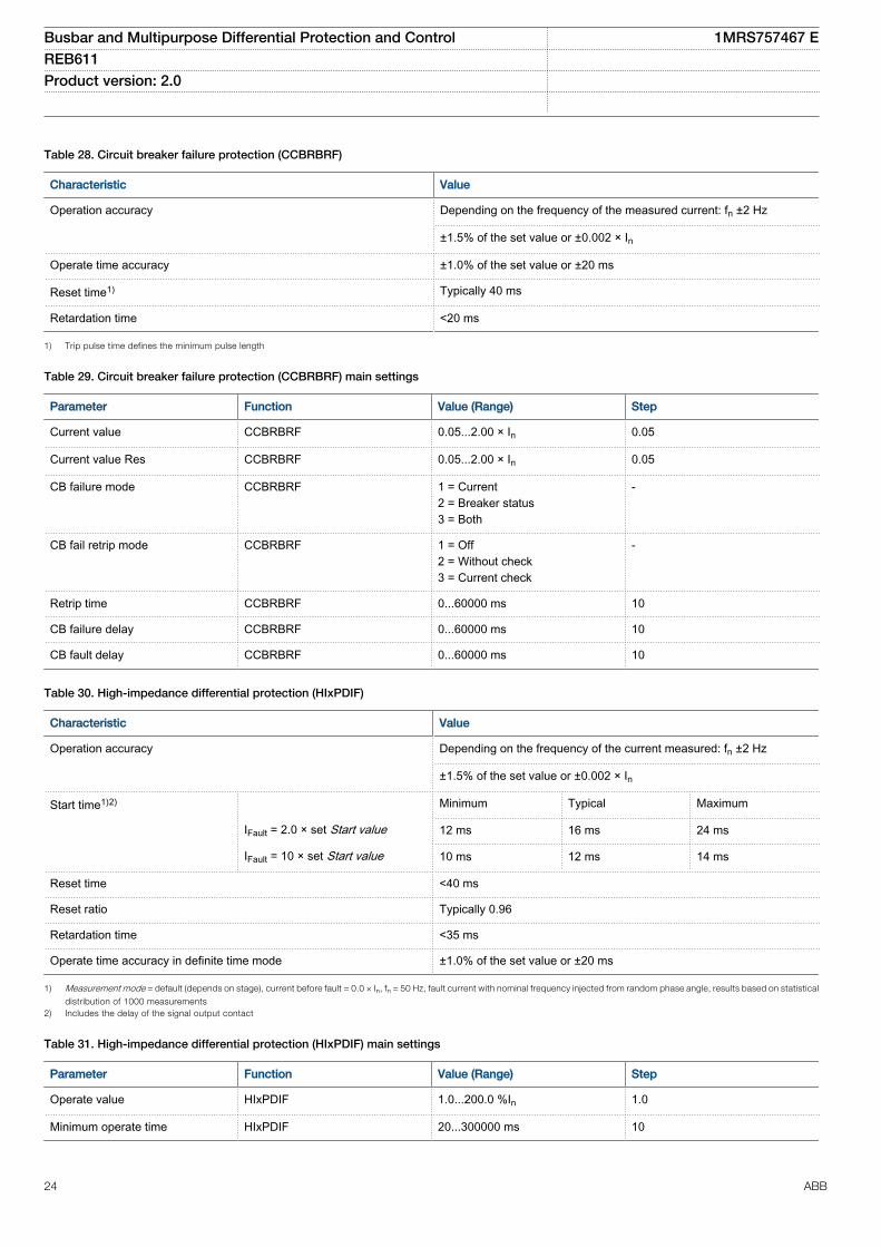
Table 28. Circuit breaker failure protection (CCBRBRF)
Characteristic Value
Operation accuracy Depending on the frequency of the measured current: fn ±2 Hz
±1.5% of the set value or ±0.002 × In
Operate time accuracy ±1.0% of the set value or ±20 ms
Reset time1) Typically 40 ms
Retardation time <20 ms
1) Trip pulse time defines the minimum pulse length
Table 29. Circuit breaker failure protection (CCBRBRF) main settings
Parameter Function Value (Range) Step
Current value CCBRBRF 0.05...2.00 × In 0.05
Current value Res CCBRBRF 0.05...2.00 × In 0.05
CB failure mode CCBRBRF 1 = Current2 = Breaker status3 = Both
-
CB fail retrip mode CCBRBRF 1 = Off2 = Without check3 = Current check
-
Retrip time CCBRBRF 0...60000 ms 10
CB failure delay CCBRBRF 0...60000 ms 10
CB fault delay CCBRBRF 0...60000 ms 10
Table 30. High-impedance differential protection (HIxPDIF)
Characteristic Value
Operation accuracy Depending on the frequency of the current measured: fn ±2 Hz
±1.5% of the set value or ±0.002 × In
Start time1)2) Minimum Typical Maximum
IFault = 2.0 × set Start value 12 ms 16 ms 24 ms
IFault = 10 × set Start value 10 ms 12 ms 14 ms
Reset time <40 ms
Reset ratio Typically 0.96
Retardation time <35 ms
Operate time accuracy in definite time mode ±1.0% of the set value or ±20 ms
1) Measurement mode = default (depends on stage), current before fault = 0.0 × In, fn = 50 Hz, fault current with nominal frequency injected from random phase angle, results based on statistical
distribution of 1000 measurements2) Includes the delay of the signal output contact
Table 31. High-impedance differential protection (HIxPDIF) main settings
Parameter Function Value (Range) Step
Operate value HIxPDIF 1.0...200.0 %In 1.0
Minimum operate time HIxPDIF 20...300000 ms 10
Busbar and Multipurpose Differential Protection and Control 1MRS757467 EREB611 Product version: 2.0
24 ABB
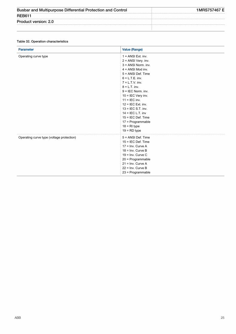
Table 32. Operation characteristics
Parameter Value (Range)
Operating curve type 1 = ANSI Ext. inv.2 = ANSI Very. inv.3 = ANSI Norm. inv.4 = ANSI Mod inv.5 = ANSI Def. Time6 = L.T.E. inv.7 = L.T.V. inv.8 = L.T. inv.9 = IEC Norm. inv.10 = IEC Very inv.11 = IEC inv.12 = IEC Ext. inv.13 = IEC S.T. inv.14 = IEC L.T. inv15 = IEC Def. Time17 = Programmable18 = RI type19 = RD type
Operating curve type (voltage protection) 5 = ANSI Def. Time15 = IEC Def. Time17 = Inv. Curve A18 = Inv. Curve B19 = Inv. Curve C20 = Programmable21 = Inv. Curve A22 = Inv. Curve B23 = Programmable
Busbar and Multipurpose Differential Protection and Control 1MRS757467 EREB611 Product version: 2.0
ABB 25
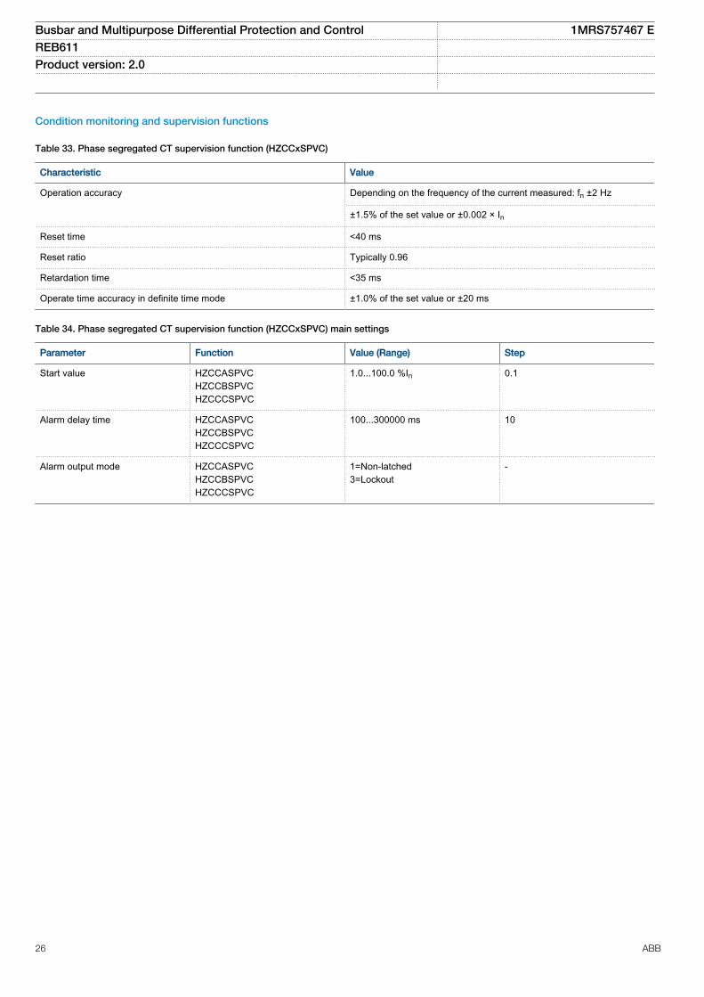
Condition monitoring and supervision functions
Table 33. Phase segregated CT supervision function (HZCCxSPVC)
Characteristic Value
Operation accuracy Depending on the frequency of the current measured: fn ±2 Hz
±1.5% of the set value or ±0.002 × In
Reset time <40 ms
Reset ratio Typically 0.96
Retardation time <35 ms
Operate time accuracy in definite time mode ±1.0% of the set value or ±20 ms
Table 34. Phase segregated CT supervision function (HZCCxSPVC) main settings
Parameter Function Value (Range) Step
Start value HZCCASPVCHZCCBSPVCHZCCCSPVC
1.0...100.0 %In 0.1
Alarm delay time HZCCASPVCHZCCBSPVCHZCCCSPVC
100...300000 ms 10
Alarm output mode HZCCASPVCHZCCBSPVCHZCCCSPVC
1=Non-latched3=Lockout
-
Busbar and Multipurpose Differential Protection and Control 1MRS757467 EREB611 Product version: 2.0
26 ABB
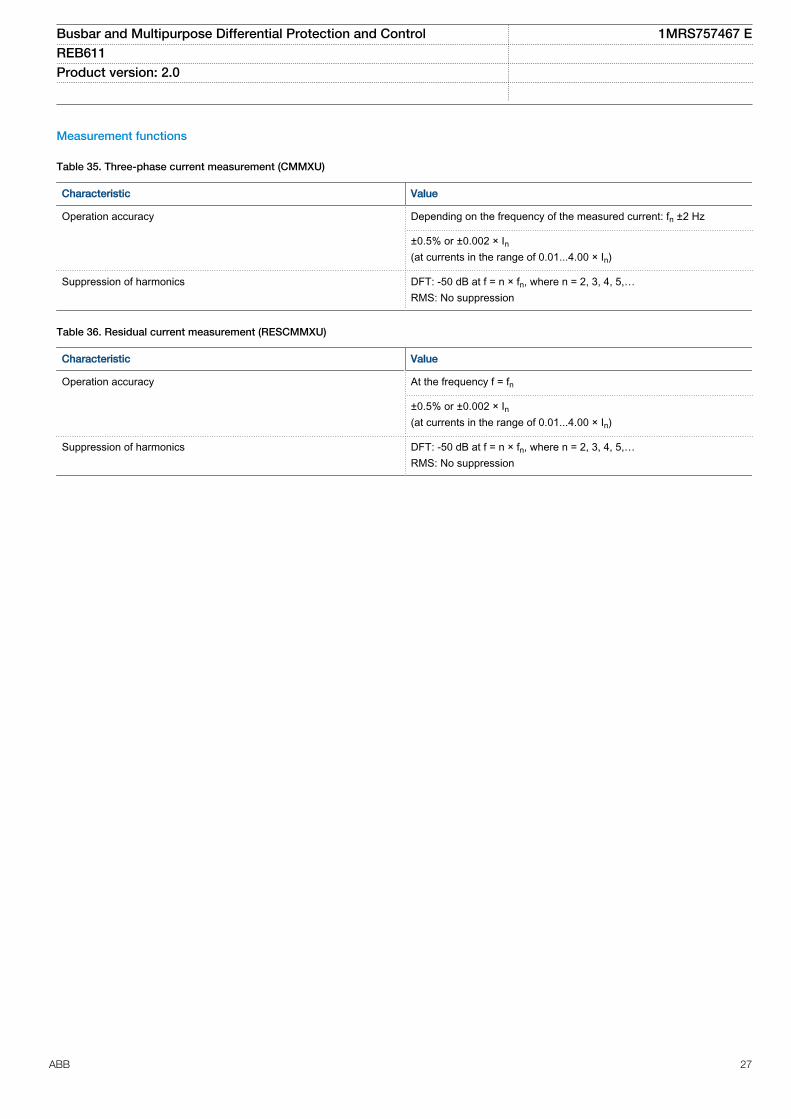
Measurement functions
Table 35. Three-phase current measurement (CMMXU)
Characteristic Value
Operation accuracy Depending on the frequency of the measured current: fn ±2 Hz
±0.5% or ±0.002 × In(at currents in the range of 0.01...4.00 × In)
Suppression of harmonics DFT: -50 dB at f = n × fn, where n = 2, 3, 4, 5,…RMS: No suppression
Table 36. Residual current measurement (RESCMMXU)
Characteristic Value
Operation accuracy At the frequency f = fn
±0.5% or ±0.002 × In(at currents in the range of 0.01...4.00 × In)
Suppression of harmonics DFT: -50 dB at f = n × fn, where n = 2, 3, 4, 5,…RMS: No suppression
Busbar and Multipurpose Differential Protection and Control 1MRS757467 EREB611 Product version: 2.0
ABB 27
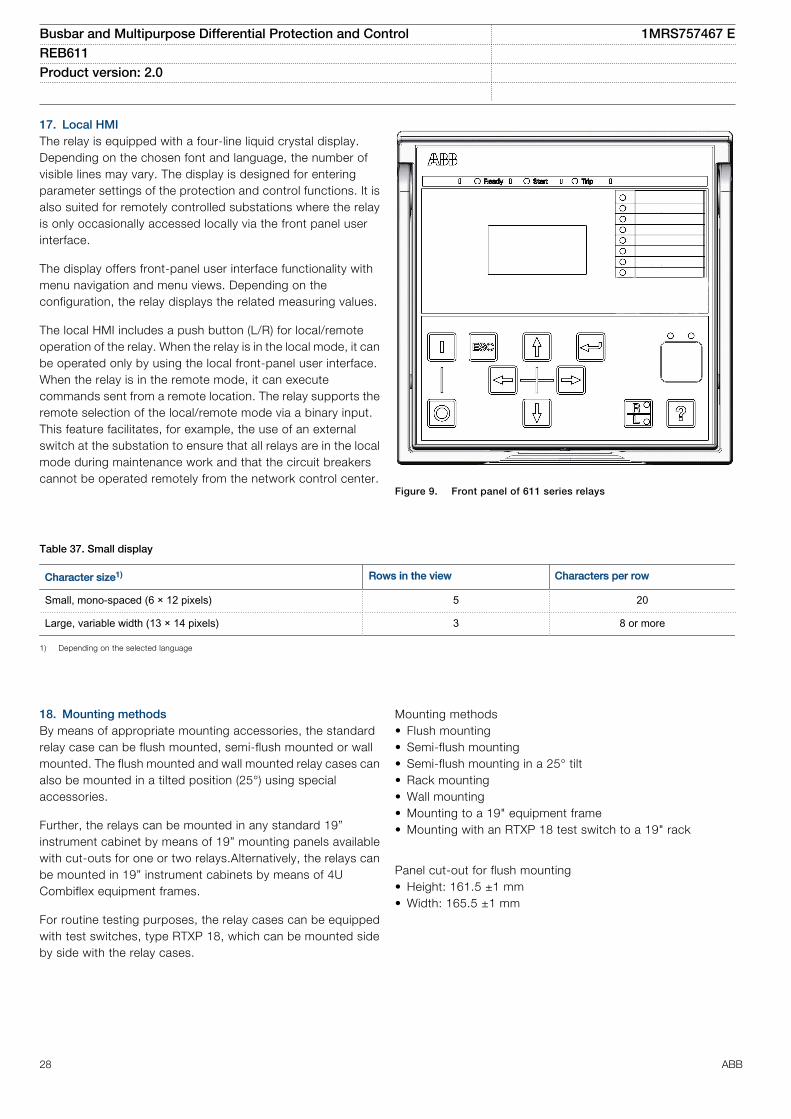
17. Local HMIThe relay is equipped with a four-line liquid crystal display.Depending on the chosen font and language, the number ofvisible lines may vary. The display is designed for enteringparameter settings of the protection and control functions. It isalso suited for remotely controlled substations where the relayis only occasionally accessed locally via the front panel userinterface.
The display offers front-panel user interface functionality withmenu navigation and menu views. Depending on theconfiguration, the relay displays the related measuring values.
The local HMI includes a push button (L/R) for local/remoteoperation of the relay. When the relay is in the local mode, it canbe operated only by using the local front-panel user interface.When the relay is in the remote mode, it can executecommands sent from a remote location. The relay supports theremote selection of the local/remote mode via a binary input.This feature facilitates, for example, the use of an externalswitch at the substation to ensure that all relays are in the localmode during maintenance work and that the circuit breakerscannot be operated remotely from the network control center.
GUID-8DC31119-E1C4-42DA-848B-968FBF8F8F53 V1 EN
Figure 9. Front panel of 611 series relays
Table 37. Small display
Character size1) Rows in the view Characters per row
Small, mono-spaced (6 × 12 pixels) 5 20
Large, variable width (13 × 14 pixels) 3 8 or more
1) Depending on the selected language
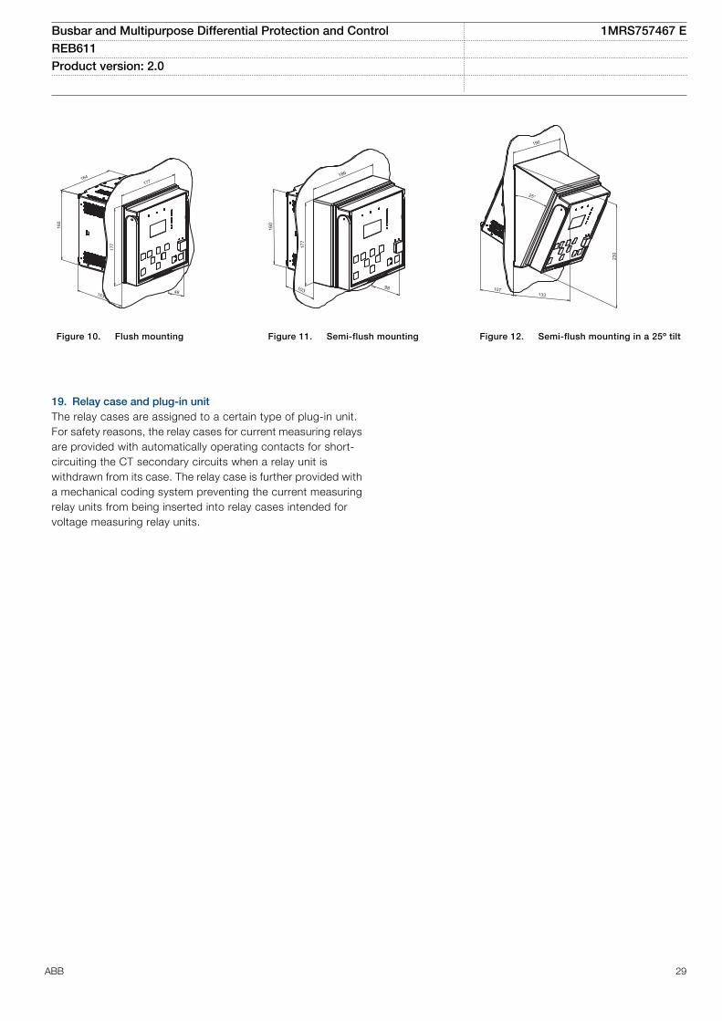
18. Mounting methodsBy means of appropriate mounting accessories, the standardrelay case can be flush mounted, semi-flush mounted or wallmounted. The flush mounted and wall mounted relay cases canalso be mounted in a tilted position (25°) using specialaccessories.
Further, the relays can be mounted in any standard 19”instrument cabinet by means of 19” mounting panels availablewith cut-outs for one or two relays.Alternatively, the relays canbe mounted in 19” instrument cabinets by means of 4UCombiflex equipment frames.
For routine testing purposes, the relay cases can be equippedwith test switches, type RTXP 18, which can be mounted sideby side with the relay cases.
Mounting methods• Flush mounting• Semi-flush mounting• Semi-flush mounting in a 25° tilt• Rack mounting• Wall mounting• Mounting to a 19" equipment frame• Mounting with an RTXP 18 test switch to a 19" rack
Panel cut-out for flush mounting• Height: 161.5 ±1 mm• Width: 165.5 ±1 mm
Busbar and Multipurpose Differential Protection and Control 1MRS757467 EREB611 Product version: 2.0
28 ABB
48153
160
177
177164
GUID-0ED32BE0-C610-4171-81A9-321735932451 V1 EN
Figure 10. Flush mounting
98
160
186
177
103
GUID-2B67CC71-7A0E-4EC8-86AA-9E94EE3C0BAF V1 EN
Figure 11. Semi-flush mounting
230
133107
25°
190
GUID-78E3ECC3-F2C7-4EFE-BC94-CAF89B5CA6D0 V1 EN
Figure 12. Semi-flush mounting in a 25º tilt
19. Relay case and plug-in unitThe relay cases are assigned to a certain type of plug-in unit.For safety reasons, the relay cases for current measuring relaysare provided with automatically operating contacts for short-circuiting the CT secondary circuits when a relay unit iswithdrawn from its case. The relay case is further provided witha mechanical coding system preventing the current measuringrelay units from being inserted into relay cases intended forvoltage measuring relay units.
Busbar and Multipurpose Differential Protection and Control 1MRS757467 EREB611 Product version: 2.0
ABB 29
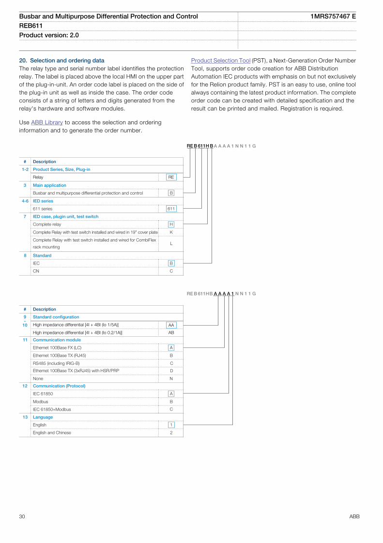
20. Selection and ordering dataThe relay type and serial number label identifies the protectionrelay. The label is placed above the local HMI on the upper partof the plug-in-unit. An order code label is placed on the side ofthe plug-in unit as well as inside the case. The order codeconsists of a string of letters and digits generated from therelay's hardware and software modules.
Use ABB Library to access the selection and orderinginformation and to generate the order number.
Product Selection Tool (PST), a Next-Generation Order NumberTool, supports order code creation for ABB DistributionAutomation IEC products with emphasis on but not exclusivelyfor the Relion product family. PST is an easy to use, online toolalways containing the latest product information. The completeorder code can be created with detailed specification and theresult can be printed and mailed. Registration is required.
# Description
1-2 Product Series, Size, Plug-in
Relay RE
3 Main application
Busbar and multipurpose differential protection and control B
4-6 IED series
611 series 611
7 IED case, plugin unit, test switch
Complete relay H
Complete Relay with test switch installed and wired in 19” cover plate K
Complete Relay with test switch installed and wired for CombiFlex
rack mountingL
8 Standard
IEC B
CN C
RE B 611 H B A A A A 1 N N 1 1 G
GUID-3CD1BE4B-5A40-4687-9C87-FA8150C2B732 V4 EN
# Description
9-
10
Standard configuration
High impedance differential [4I + 4BI (Io 1/5A)] AA
11 Communication module
Ethernet 100Base FX (LC) A
RS485 (including IRIG-B) C
12 Communication (Protocol)
IEC 61850 A
Modbus B
IEC 61850+Modbus C
13 Language
English 1
English and Chinese 2
RE B 611H B A A A A 1 N N 1 1 G
High impedance differential [4I + 4BI (Io 0.2/1A)] AB
Ethernet 100Base TX (RJ45)
None N
Ethernet 100Base TX (3xRJ45) with HSR/PRP
B
D
GUID-06A17D23-AA08-49DE-BBE6-1E4E058065E9 V4 EN
Busbar and Multipurpose Differential Protection and Control 1MRS757467 EREB611 Product version: 2.0
30 ABB
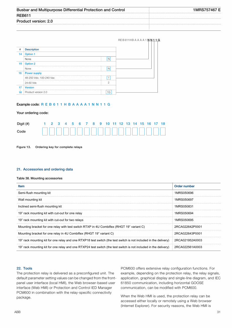
# Description
14 Option 1
None
15 Option 2
None N
16 Power supply
48-250 Vdc; 100-240 Vac 1
24-60 Vdc 2
17-
18
Version
Product version 2.0 1G
RE B 611H B A A A A 1 N N 1 1 G
N
GUID-295664AE-A576-42FC-B535-CCD4DBBC726F V3 EN
Example code: R E B 6 1 1 H B A A A A 1 N N 1 1 G
Your ordering code:
Digit (#) 1 2 3 4 5 6 7 8 9 10 11 12 13 14 15 16 17 18
Code
GUID-2680DAE0-3BF4-458D-97EF-9D141CEB7EC2 V3 EN
Figure 13. Ordering key for complete relays
21. Accessories and ordering data
Table 38. Mounting accessories
Item Order number
Semi-flush mounting kit 1MRS050696
Wall mounting kit 1MRS050697
Inclined semi-flush mounting kit 1MRS050831
19” rack mounting kit with cut-out for one relay 1MRS050694
19” rack mounting kit with cut-out for two relays 1MRS050695
Mounting bracket for one relay with test switch RTXP in 4U Combiflex (RHGT 19” variant C) 2RCA022642P0001
Mounting bracket for one relay in 4U Combiflex (RHGT 19” variant C) 2RCA022643P0001
19” rack mounting kit for one relay and one RTXP18 test switch (the test switch is not included in the delivery) 2RCA021952A0003
19” rack mounting kit for one relay and one RTXP24 test switch (the test switch is not included in the delivery) 2RCA022561A0003
22. ToolsThe protection relay is delivered as a preconfigured unit. Thedefault parameter setting values can be changed from the front-panel user interface (local HMI), the Web browser-based userinterface (Web HMI) or Protection and Control IED ManagerPCM600 in combination with the relay-specific connectivitypackage.
PCM600 offers extensive relay configuration functions. Forexample, depending on the protection relay, the relay signals,application, graphical display and single-line diagram, and IEC61850 communication, including horizontal GOOSEcommunication, can be modified with PCM600.
When the Web HMI is used, the protection relay can beaccessed either locally or remotely using a Web browser(Internet Explorer). For security reasons, the Web HMI is
Busbar and Multipurpose Differential Protection and Control 1MRS757467 EREB611 Product version: 2.0
ABB 31
enabled by default but it can be enabled via the local HMI. TheWeb HMI functionality can be limited to read-only access.
The relay connectivity package is a collection of software andspecific relay information, which enables system products andtools to connect and interact with the protection relay. Theconnectivity packages reduce the risk of errors in system
integration, minimizing device configuration and setup times.Further, the connectivity packages for protection relays of thisproduct series include a flexible update tool for adding oneadditional local HMI language to the protection relay. Theupdate tool is activated using PCM600, and it enables multipleupdates of the additional HMI language, thus offering flexiblemeans for possible future language updates.
Table 39. Tools
Description Version
PCM600 2.7 or later
Web browser IE 8.0, IE 9.0, IE 10.0 or IE 11.0
REB611 Connectivity Package 2.0 or later
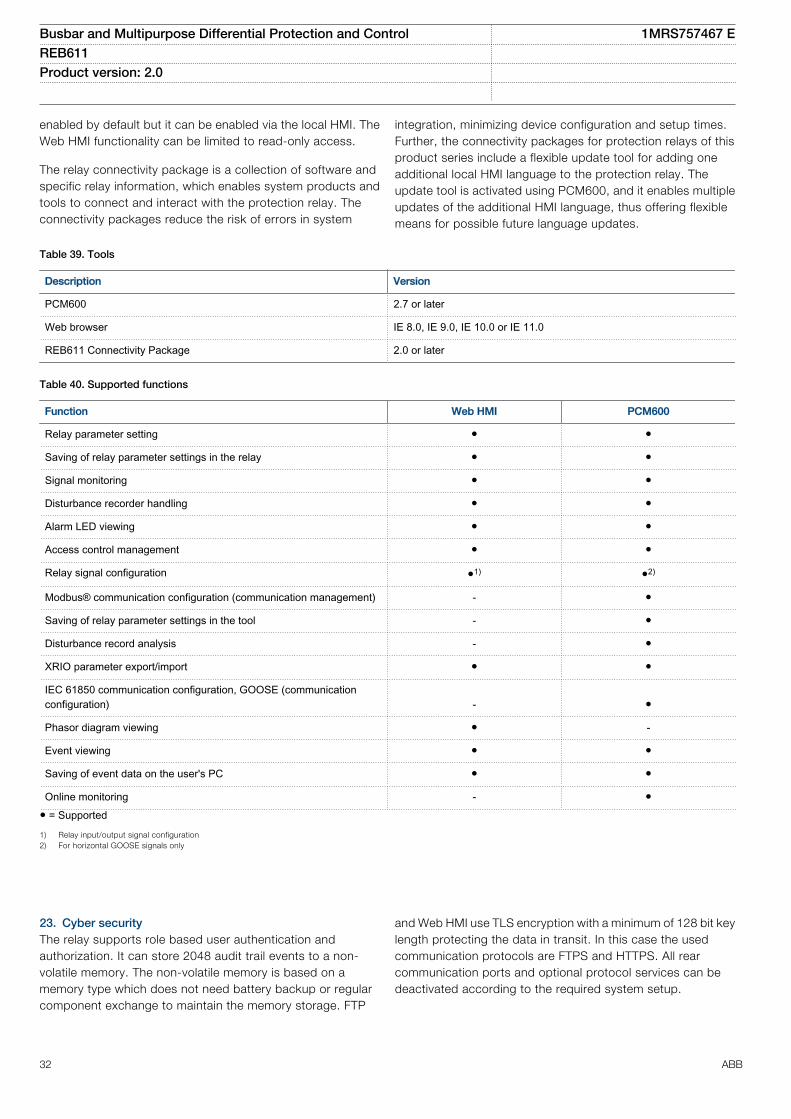
Table 40. Supported functions
Function Web HMI PCM600
Relay parameter setting ● ●
Saving of relay parameter settings in the relay ● ●
Signal monitoring ● ●
Disturbance recorder handling ● ●
Alarm LED viewing ● ●
Access control management ● ●
Relay signal configuration ●1) ●2)
Modbus® communication configuration (communication management) - ●
Saving of relay parameter settings in the tool - ●
Disturbance record analysis - ●
XRIO parameter export/import ● ●
IEC 61850 communication configuration, GOOSE (communicationconfiguration) - ●
Phasor diagram viewing ● -
Event viewing ● ●
Saving of event data on the user's PC ● ●
Online monitoring - ●● = Supported
1) Relay input/output signal configuration2) For horizontal GOOSE signals only
23. Cyber securityThe relay supports role based user authentication andauthorization. It can store 2048 audit trail events to a non-volatile memory. The non-volatile memory is based on amemory type which does not need battery backup or regularcomponent exchange to maintain the memory storage. FTP
and Web HMI use TLS encryption with a minimum of 128 bit keylength protecting the data in transit. In this case the usedcommunication protocols are FTPS and HTTPS. All rearcommunication ports and optional protocol services can bedeactivated according to the required system setup.
Busbar and Multipurpose Differential Protection and Control 1MRS757467 EREB611 Product version: 2.0
32 ABB
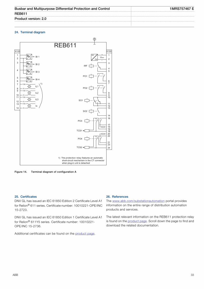
24. Terminal diagram
REB611
16
17
1918
X100
67
89
10
111213
15
14
2
1
3
45
22
212324
SO2
TCS2
PO4
SO1
TCS1
PO3
PO2
PO1
IRF
+
-Uaux
20
1) The protection relay features an automatic short-circuit mechanism in the CT connector when plug-in unit is detached
1)
X120
12
3
4
567
89
1011
12
14Io
IL1
IL2
BI 4
BI 3
BI 2
BI 1
IL3
1/5A
N1/5A
N1/5A
N1/5A
N
13
GUID-BA0109A6-62B2-43A2-90B5-E3636790E5AF V2 EN
Figure 14. Terminal diagram of configuration A
25. CertificatesDNV GL has issued an IEC 61850 Edition 2 Certificate Level A1
for Relion® 611 series. Certificate number: 10010221-OPE/INC15-2723.
DNV GL has issued an IEC 61850 Edition 1 Certificate Level A1
for Relion® 611Y5 series. Certificate number: 10010221-OPE/INC 15-2736.
Additional certificates can be found on the product page.
26. ReferencesThe www.abb.com/substationautomation portal providesinformation on the entire range of distribution automationproducts and services.
The latest relevant information on the REB611 protection relayis found on the product page. Scroll down the page to find anddownload the related documentation.
Busbar and Multipurpose Differential Protection and Control 1MRS757467 EREB611 Product version: 2.0
ABB 33
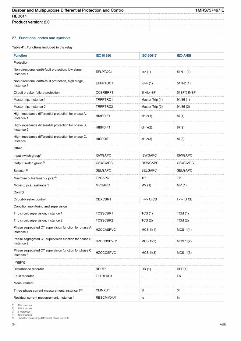
27. Functions, codes and symbols
Table 41. Functions included in the relay
Function IEC 61850 IEC 60617 IEC-ANSI
Protection
Non-directional earth-fault protection, low stage,instance 1 EFLPTOC1 Io> (1) 51N-1 (1)
Non-directional earth-fault protection, high stage,instance 1 EFHPTOC1 Io>> (1) 51N-2 (1)
Circuit breaker failure protection CCBRBRF1 3I>/Io>BF 51BF/51NBF
Master trip, instance 1 TRPPTRC1 Master Trip (1) 94/86 (1)
Master trip, instance 2 TRPPTRC2 Master Trip (2) 94/86 (2)
High-impedance differential protection for phase A,instance 1 HIAPDIF1 dHi>(1) 87(1)
High-impedance differential protection for phase B,instance 2 HIBPDIF1 dHi>(2) 87(2)
High-impedance differential protection for phase C,instance 3 HICPDIF1 dHi>(3) 87(3)
Other
Input switch group1) ISWGAPC ISWGAPC ISWGAPC
Output switch group2) OSWGAPC OSWGAPC OSWGAPC
Selector3) SELGAPC SELGAPC SELGAPC
Minimum pulse timer (2 pcs)4) TPGAPC TP TP
Move (8 pcs), instance 1 MVGAPC MV (1) MV (1)
Control
Circuit-breaker control CBXCBR1 I <-> O CB I <-> O CB
Condition monitoring and supervision
Trip circuit supervision, instance 1 TCSSCBR1 TCS (1) TCM (1)
Trip circuit supervision, instance 2 TCSSCBR2 TCS (2) TCM (2)
Phase segregated CT supervision function for phase A,instance 1 HZCCASPVC1 MCS 1I(1) MCS 1I(1)
Phase segregated CT supervision function for phase B,instance 2 HZCCBSPVC1 MCS 1I(2) MCS 1I(2)
Phase segregated CT supervision function for phase C,instance 3 HZCCCSPVC1 MCS 1I(3) MCS 1I(3)
Logging
Disturbance recorder RDRE1 DR (1) DFR(1)
Fault recorder FLTRFRC1 - FR
Measurement
Three-phase current measurement, instance 15) CMMXU1 3I 3I
Residual current measurement, instance 1 RESCMMXU1 Io In
1) 10 instances2) 20 instances3) 6 instances4) 10 instances5) Used for measuring differential phase currents
Busbar and Multipurpose Differential Protection and Control 1MRS757467 EREB611 Product version: 2.0
34 ABB
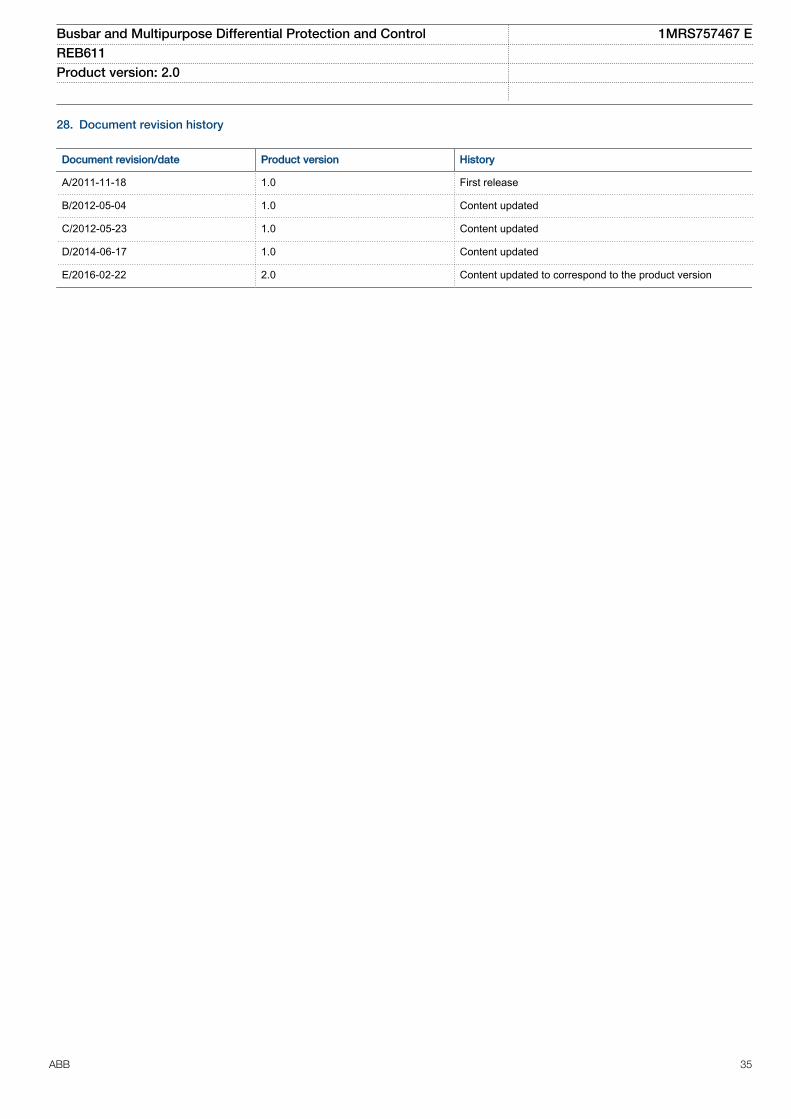
28. Document revision history
Document revision/date Product version History
A/2011-11-18 1.0 First release
B/2012-05-04 1.0 Content updated
C/2012-05-23 1.0 Content updated
D/2014-06-17 1.0 Content updated
E/2016-02-22 2.0 Content updated to correspond to the product version
Busbar and Multipurpose Differential Protection and Control 1MRS757467 EREB611 Product version: 2.0
ABB 35

36


Contact us
ABB OyMedium Voltage Products,Distribution AutomationP.O. Box 699FI-65101 VAASA, FinlandPhone +358 10 22 11Fax +358 10 22 41094
www.abb.com/mediumvoltage
www.abb.com/substationautomation
1MR
S75
7467
E©
Cop
yrig
ht 2
016
AB
B. A
ll rig
hts
rese
rved
.