1mrk505172-Ben a en Busbar Differential Protection Ied Reb670 Pre-configured
36
Page 1 Buyer's Guide Busbar differential protection IED REB 670 Pre-configured 1MRK 505 172-BEN Revision: A Issued: February 2007 Data subject to change without notice Features • IED for differential protection of busbars, meshed corners and T-protection • Three-phase version of the IED with two low-impedance differential protection zones and four or eight three-phase CT inputs • One-phase version of the IED with two low-impedance differential protection zones and twelve or twenty-four CT inputs. Three IEDs per protection scheme are usually required, one for each phase • Three configuration alternatives are available – ready to connect • Two low-impedance differential protection zones with: - High speed tripping for internal faults. Typical operating time 12 ms - Complete stability for through faults, with heavy CT saturation, and a maximum rema- nence in the CT core at auto-reclosing - Low CT requirement, only 2 milliseconds to saturation needed for correct operation - Intelligent detection for open or shorted CT secondary circuits and configurable blocking of differential protection zone - Different CT ratios can be easily adjusted via built-in HMI or from PC with the software tool PCM 600 - Sensitive differential protection stage for power systems with limited earth-fault current • Software driven dynamic Zone Selection (i.e. busbar replica) ensures: - No switching in CT secondary circuits neither interposing CTs are required - Easy adaptation to different substation lay- outs such as: single or double bus (with transfer bus), one-and-half or double breaker, etc. - Simple adaptation to buses with only one set of CTs in the bus-section or bus-coupler bays - Selective tripping i.e. routing of busbar differ- ential protection trip commands to all circuit breakers connected to the faulty zone - Marshaling of integrated or external breaker failure protection backup-trip commands to all surrounding circuit breakers - Merging of the two differential zones when required (i.e. during load transfer in double busbar stations) - Disconnector and/or circuit breaker status supervision • Integrated overall check zone independent from any disconnector position is included for increased security for complex station layouts • Breaker failure protection is optionally available for every CT input. Main features of integrated breaker failure functions are: - Operation mode settable as current based, breaker contact based or combination of the two - Single- or three-phase starting - Re-trip facility to the faulty feeder breaker with or without current check • Non-directional, inverse or definite time delayed overcurrent protection with four steps is option- ally available for every CT input. It can be used as: - End-fault or blind-spot protection - Main or back-up protection for the feeder or bus-tie bays • Built-in data communication modules for station bus IEC 61850-8-1 • Data communication modules for station bus IEC 60870-5-103, LON and SPA • Programmable logic gates as AND, OR, INV, Timers etc. are available for customized solu- tions • On screen display of all measured bay currents and all calculated differential currents • On screen display of bay-to-zone allocations and status of connected switchgear devices • Cost effective summation type differential princi- ple is available for less demanding applications
-
Upload
bijaya-kumar-mohanty -
Category
Documents
-
view
92 -
download
5
Transcript of 1mrk505172-Ben a en Busbar Differential Protection Ied Reb670 Pre-configured

Buyer's GuidePre-configured
Busbar differential protection IED REB 670
1MRK 505 172-BENRevision: A
Page 1
Issued: February 2007Data subject to change without notice
Features • IED for differential protection of busbars, meshed corners and T-protection
• Three-phase version of the IED with two low-impedance differential protection zones and four or eight three-phase CT inputs
• One-phase version of the IED with two low-impedance differential protection zones and twelve or twenty-four CT inputs. Three IEDs per protection scheme are usually required, one for each phase
• Three configuration alternatives are available – ready to connect
• Two low-impedance differential protection zones with:
- High speed tripping for internal faults. Typical operating time 12 ms
- Complete stability for through faults, with heavy CT saturation, and a maximum rema-nence in the CT core at auto-reclosing
- Low CT requirement, only 2 milliseconds to saturation needed for correct operation
- Intelligent detection for open or shorted CT secondary circuits and configurable blocking of differential protection zone
- Different CT ratios can be easily adjusted via built-in HMI or from PC with the software tool PCM 600
- Sensitive differential protection stage for power systems with limited earth-fault current
• Software driven dynamic Zone Selection (i.e. busbar replica) ensures:
- No switching in CT secondary circuits neither interposing CTs are required
- Easy adaptation to different substation lay-outs such as: single or double bus (with transfer bus), one-and-half or double breaker, etc.
- Simple adaptation to buses with only one set of CTs in the bus-section or bus-coupler bays
- Selective tripping i.e. routing of busbar differ-ential protection trip commands to all circuit breakers connected to the faulty zone
- Marshaling of integrated or external breaker failure protection backup-trip commands to all surrounding circuit breakers
- Merging of the two differential zones when required (i.e. during load transfer in double busbar stations)
- Disconnector and/or circuit breaker status supervision
• Integrated overall check zone independent from any disconnector position is included for increased security for complex station layouts
• Breaker failure protection is optionally available for every CT input. Main features of integrated breaker failure functions are:
- Operation mode settable as current based, breaker contact based or combination of the two
- Single- or three-phase starting- Re-trip facility to the faulty feeder breaker
with or without current check• Non-directional, inverse or definite time delayed
overcurrent protection with four steps is option-ally available for every CT input. It can be used as:
- End-fault or blind-spot protection- Main or back-up protection for the feeder or
bus-tie bays• Built-in data communication modules for station
bus IEC 61850-8-1
• Data communication modules for station bus IEC 60870-5-103, LON and SPA
• Programmable logic gates as AND, OR, INV, Timers etc. are available for customized solu-tions
• On screen display of all measured bay currents and all calculated differential currents
• On screen display of bay-to-zone allocations and status of connected switchgear devices
• Cost effective summation type differential princi-ple is available for less demanding applications

Busbar differential protection IED REB 670 Buyer's GuidePre-configured
1MRK 505 172-BENRevision: A, Page 2
• Apparatus position indications can be sent between single phase REB 670 with optional LDCM optical communicaton module
• Auto Reclose scheme for busbar restoration
• Integrated disturbance and event recorder for up to 40 analog and 96 binary signals
• Time synchronization over IEC 61850-8-1, LON, SPA, binary input or with optional GPS module
• Analog measurements accuracy up to below 0.25% for current and voltage and with site cali-bration to optimize total accuracy
• Versatile local human-machine interface
• Extensive self-supervision with internal event recorder
• Six independent groups of complete setting parameters with password protection
• Powerful software PC tool for setting, distur-bance evaluation and configuration
Application REB 670 is designed for the selective, reliable and fast differential protection of busbars, T-connec-tions and meshed corners. REB 670 can be used for protection of single and double busbar with or without transfer bus, double circuit breaker or one-and-half circuit breaker stations. The IED is applicable for the protection of medium voltage (MV), high voltage (HV) and extra high voltage (EHV) installations at a power system frequency of 50Hz or 60Hz. The IED can detect all types of internal phase-to-phase and phase-to-earth faults in solidly earthed or low impedance earthed power systems, as well as all internal multi-phase faults in isolated or high-impedance earthed power sys-tems.
REB 670 has very low requirements on the main current transformers (i.e. CTs) and no interposing current transformers are necessary. For all applica-tions, it is possible to include and mix main CTs with 1A and 5A rated secondary current within the same protection zone. Typically, CTs with up to 10:1 ratio difference can be used within the same differential protection zone. Adjustment for differ-ent main CT ratios is achieved numerically by a parameter setting.
The numerical, low-impedance differential protec-tion function is designed for fast and selective pro-tection for faults within protected zone. All connected CT inputs are provided with a restraint feature. The minimum pick-up value for the differ-ential current is set to give a suitable sensitivity for all internal faults. For busbar protection applica-
tions typical setting value for the minimum differ-ential operating current is from 50% to 150% of the biggest CT. This setting is made directly in pri-mary amperes. The operating slope for the differ-ential operating characteristic is fixed to 53% in the algorithm.
The fast tripping time of the low-impedance differ-ential protection function is especially advantages for power system networks with high fault levels or where fast fault clearance is required for power system stability.
The advanced open CT detection algorithm detects instantly the open CT secondary circuits and pre-vents differential protection operation without any need for additional check zone.
Differential protection zones in REB 670 include a sensitive operational level. This sensitive opera-tional level is designed to be able to detect internal busbar earth faults in low impedance earthed power systems (i.e. power systems where the earth-fault current is limited to a certain level, typ-ically between 300A and 2000A primary by a neu-tral point reactor or resistor). Alternatively this sensitive level can be used when high sensitivity is required from busbar differential protection (i.e. energizing of the bus via long line).
Overall operating characteristic of the differential function in REB 670 is shown in the following fig-ure.

Busbar differential protection IED REB 670 Buyer's GuidePre-configured
1MRK 505 172-BENRevision: A, Page 3
Figure 1: REB 670 operating characteristic
Integrated overall check zone feature, independent from any disconnector position, is available. It can be used in double busbar stations to secure stabil-ity of the busbar differential protection in case of entirely wrong status indication of busbar discon-nector in any of the feeder bays.
Flexible, software based dynamic Zone Selection enables easy and fast adaptation to the most com-mon substation arrangements such as single busbar with or without transfer bus, double busbar with or without transfer bus, one-and-a-half breaker sta-tions, double busbar-double breaker stations, ring busbars, etc. The software based dynamic Zone Selections ensures:
• Dynamic linking of measured CT currents to the appropriate differential protection zone as required by substation topology
• Efficient merging of the two differential zones when required by substation topology (i.e. load-transfer)
• Selective operation of busbar differential pro-tection ensures tripping only of circuit break-ers connected to the faulty zone
• Correct marshaling of backup-trip commands from internally integrated or external circuit breaker failure protections to all surrounding circuit breakers
• Easy incorporation of bus-section and/or bus-coupler bays (i.e. tie-breakers) with one or two sets of CTs into the protection scheme
• Disconnector and/or circuit breaker status supervision
Advanced Zone Selection logic accompanied by optionally available end-fault and/or circuit breaker failure protections ensure minimum possi-ble tripping time and selectivity for faults within the blind spot or the end zone between bay CT and bay circuit breaker. Therefore REB 670 offers best possible coverage for such faults in feeder and bus-section/bus-coupler bays.
Optionally available circuit breaker failure protec-tion, one for every CT input into REB 670, offers secure local back-up protection for the circuit breakers in the station.
Optionally available four-stage, non-directional overcurrent protections, one for every CT input into REB 670, provide remote backup functional-ity for connected feeders and remote-end stations.
It is normal practice to have just one set of busbar protection relays per busbar. Nevertheless some utilities do apply two independent busbar protec-tion relays per zone of protection. REB 670 IED fits both solutions.
A simplified bus differential protection for multi-phase faults and earth faults can be obtained by using a single, one-phase REB 670 IED with external auxiliary summation current transformers.
The wide application flexibility makes this product an excellent choice for both new installations and the refurbishment of existing installations.
Description of 3 ph variant A20Three-phase version of the IED with two low-impedance differential protection zones and four three-phase CT inputs (A20). This version is
Differential protectionoperation characteristic
Operateregion
Diff Oper Level
I d [P
rimar
y Am
ps]
Iin [Primary Amps]
s=0.53
I d=I in
Sensitivedifferentialprotection
en06000142.vsd
Sensitive Oper Level Sens Iin Block

Busbar differential protection IED REB 670 Buyer's GuidePre-configured
1MRK 505 172-BENRevision: A, Page 4
available in 1/2 of 19” case. The version is intended for simpler applications such as T-con-nections, meshed corners, etc.
Description of 3 ph variant A31Three-phase version of the IED with two low-impedance differential protection zones and eight three-phase CT inputs (A31). This version is available in full 19” case. The version is intended for applications on smaller busbars, with up to two zones and eight CT inputs.
Description of 1 ph variants B20 and B21One-phase version of the IED with two low-impedance differential protection zones and twelve CT inputs (B20, B21).
• This version is available in either 1/2 of 19” (B20) or full 19” (B21) case.
• Due to three available binary input modules, the IED in 1/2 of 19” case (B20) is intended for applications without need for dynamic Zone Selection such typical examples are sub-stations with single busbar with or without bus-section breaker, one-and-half breaker or double breaker arrangements. Three such IEDs offer cost effective solutions for such simple substation arrangements with up to twelve CT inputs.
• The IED in full 19” case (B21) is intended for applications in substations where dynamic Zone Selection or bigger number of binary inputs and outputs is needed. Such stations for example are double busbar station with or without transfer bus with up to 12 CT inputs.
• This version can be optionally used with exter-nal auxiliary summation transformers.
Description of 1 ph variant B31One-phase version of the IED with two low-impedance differential protection zones and twenty-four CT inputs (B31).
• This version is available in full 19” case. The IED is intended for busbar protection applica-tions in big substations where dynamic Zone Selection, quite large number of binary inputs and outputs and many CT inputs are needed. The IED includes two differential zones and twenty-four CT inputs.
• This version can be optionally used with exter-nal auxiliary summation transformers.
Available configurations for pre-configured REB 670Three configurations has been made available for pre-configured REB 670 IED. It shall be noted
that all three configurations include the following features:
• fully configured for the total available number of bays in each REB 670 variant
• facility to take any bay out of service via built-in HMI or externally via binary input
• facility to block any of the two zones via built-in HMI or externally via binary input
• facility to block all bay trips via built-in HMI or externally via binary input, but leaving all other function in service (i.e. BBP Zones, BFP and OCP where applicable)
• facility to externaly start built-in disturbance recorder
• facility to connect external breaker failure backup trip signal from every bay
• facility to connect external bay trip signal
Configuration #1 Called X01• This configuration includes just busbar protec-
tion for simple stations layouts (i.e. One-and-a-half breaker, Double Breaker or Single Breaker stations). Additionaly it can be used for double busbar-single breaker stations where disconnector replica is done by using just b auxiliary contact from every disconnec-tor and/or circuit breakers. As a consequence no disconnector/breaker supervision will be avavaible. It is as well possible to adapt this configuration by SMT to be used as direct replacement of RED 521*1.0 terminals. This configuration is avaiable for all five REB 670 variants (i.e. A20, A31, B20, B21 & B31). It shall be noted that optional functions breaker failure protection RBRF, end fault protection and overcurrent protection POCM can be ordered together with this configuration, but they will not be pre-configured! Thus these optional functions shall be configured by the end user.
Configuration #2 Called X02• This configuration includes just busbar protec-
tion for double busbar-single breaker stations, where Zone Selection is done by using a and b auxiliary contacts from every disconnectors and/or circuit breakers. Thus full disconnec-tor/breaker supervision is avaiable. This con-figuration is avaiable for only three REB 670 variants (i.e. A31, B21 and B31). It shall be noted that optional functions breaker failure protection RBRF, end fault protection and overcurrent protection POCM can be ordered together with this configuration, but they will not be pre-configured! Thus these optional functions shall be configured by the end user.

Busbar differential protection IED REB 670 Buyer's GuidePre-configured
1MRK 505 172-BENRevision: A, Page 5
Configuration #3 Called X03• This configuration includes BBP with breaker
failure protection RBRF, end fault protection and overcurrent protection POCM for double busbar-single breaker stations, where Zone Selection is done by using a and b auxiliary contacts from every disconnectors and/or cir-cuit breakers. Thus full disconnector/breaker supervision is avaiable. This configuration is avaiable for only three REB 670 variants (i.e. A31, B21 and B31).
Application examples of REB 670Examples of typical station layouts, which can be protected with REB 670 are given below:
Figure 2: Example of T-connection
Figure 3: Example of single bus station
Figure 4: Example of single bus station with transfer bus
Figure 5: Example of double bus-single breaker station
xx06000009.vsd
BI1 BI1 BI1 BI1 BI1 BI1 BI1
QA1 QA1 QA1 QA1 QA1 QA1 QA1
QB1ZA ZB
xx06000012.vsd
BI1
QA1
QB1 QB7
BI1
QB7QB1
QA1
BI1
QB7QB1
QA1
BI1
QB7QB1
QA1
BI1
QB7QB1
QA1
ZA
ZB
BI1
QB7QB1
QA1
xx06000013.vsd
BI1
QA1
QB1 QB2
BI1
QA1
QB1 QB2
BI1
QA1
QB1 QB2
BI1
QA1
QB1 QB2
BI1
QA1
QB1 QB2BI1
QA1
BI1
QB1 QB2
QA1
ZA
ZB
xx06000014.vsd

Busbar differential protection IED REB 670 Buyer's GuidePre-configured
1MRK 505 172-BENRevision: A, Page 6
Figure 6: Example of double bus-single breaker station with transfer bus
Figure 7: Example of double bus-single breaker station with two bus-section and two bus-coupler break-ers
Figure 8: Example of one-and-a-half breakar station
BI1
QB1 QB2 QB7
BI1
QB1 QB2 QB7
BI1
QB1 QB2 QB7
BI1
QB1 QB2 QB7
BI1
QB20QB2 QB7QB1
QA1 QA1 QA1 QA1 QA1
ZAZB
xx06000015.vsd
BI1
QA1
QB1 QB2
BI1
QA1
QB1 QB2
BI1
QA1
QB1 QB2
BI1
QA1
QB1 QB2
BI1
QA1
QB1 QB2
BI1
QA1
QB1 QB2
BI1
QA1
QB1 QB2
BI1
QA1
QB1 QB2BI1
QA1
BI1 QA1
BI1 QA1
BI1
QB1 QB2
QA1
BI1
QA1
ZA1
ZB1
ZA2
ZB2
xx06000016.vsd
BI3
BI1
QA1
BI2
QA2
QA3
BI3
BI1
QA1
BI2
QA2
QA3
BI3
BI1
QA1
BI2
QA2
QA3
BI3
BI1
QA1
BI2
QA2
QA3
BI3
BI1
QA1
BI2
QA2
QA3
ZA
ZB
xx06000017.vsd

Busbar differential protection IED REB 670 Buyer's GuidePre-configured
1MRK 505 172-BENRevision: A, Page 7
Figure 9: Example of double bus-double breaker station
Figure 10: Example of mesh or ring bus station
QA1
BI1 BI2
QA2 QA1
BI1 BI2
QA2 QA1
BI1 BI2
QA2 QA1
BI1 BI2
QA2 QA1
BI1 BI2
QA2
ZA
ZB
xx06000018.vsd
QB32
QB12BI1
QA3BI3
BI8
QA4
BI4
QA2
BI2
BI5
BI6BI7
QB5QB8
QB6QB7
QB31
QB11
QB42 QB22
QB21QB41
QA1ZA1 ZA2
ZB1 ZB2
xx06000019.vsd
Busbar differential protection IED REB 670 Buyer's GuidePre-configured
1MRK 505 172-BENRevision: A, Page 8
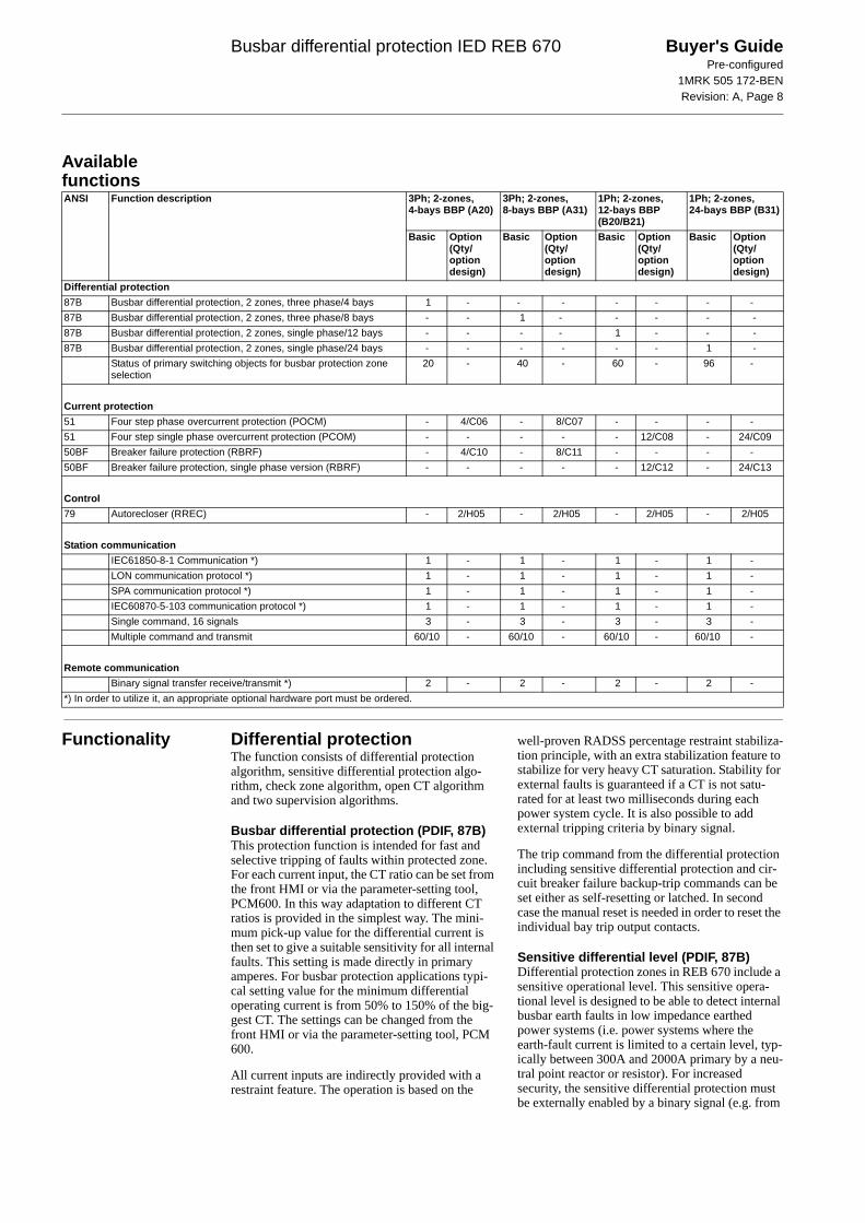
Available functions
Functionality Differential protectionThe function consists of differential protection algorithm, sensitive differential protection algo-rithm, check zone algorithm, open CT algorithm and two supervision algorithms.
Busbar differential protection (PDIF, 87B)This protection function is intended for fast and selective tripping of faults within protected zone. For each current input, the CT ratio can be set from the front HMI or via the parameter-setting tool, PCM600. In this way adaptation to different CT ratios is provided in the simplest way. The mini-mum pick-up value for the differential current is then set to give a suitable sensitivity for all internal faults. This setting is made directly in primary amperes. For busbar protection applications typi-cal setting value for the minimum differential operating current is from 50% to 150% of the big-gest CT. The settings can be changed from the front HMI or via the parameter-setting tool, PCM 600.
All current inputs are indirectly provided with a restraint feature. The operation is based on the
well-proven RADSS percentage restraint stabiliza-tion principle, with an extra stabilization feature to stabilize for very heavy CT saturation. Stability for external faults is guaranteed if a CT is not satu-rated for at least two milliseconds during each power system cycle. It is also possible to add external tripping criteria by binary signal.
The trip command from the differential protection including sensitive differential protection and cir-cuit breaker failure backup-trip commands can be set either as self-resetting or latched. In second case the manual reset is needed in order to reset the individual bay trip output contacts.
Sensitive differential level (PDIF, 87B)Differential protection zones in REB 670 include a sensitive operational level. This sensitive opera-tional level is designed to be able to detect internal busbar earth faults in low impedance earthed power systems (i.e. power systems where the earth-fault current is limited to a certain level, typ-ically between 300A and 2000A primary by a neu-tral point reactor or resistor). For increased security, the sensitive differential protection must be externally enabled by a binary signal (e.g. from
ANSI Function description 3Ph; 2-zones, 4-bays BBP (A20)
3Ph; 2-zones, 8-bays BBP (A31)
1Ph; 2-zones, 12-bays BBP (B20/B21)
1Ph; 2-zones, 24-bays BBP (B31)
Basic Option (Qty/ option design)
Basic Option (Qty/ option design)
Basic Option (Qty/ option design)
Basic Option (Qty/ option design)
Differential protection87B Busbar differential protection, 2 zones, three phase/4 bays 1 - - - - - - -87B Busbar differential protection, 2 zones, three phase/8 bays - - 1 - - - - -87B Busbar differential protection, 2 zones, single phase/12 bays - - - - 1 - - -87B Busbar differential protection, 2 zones, single phase/24 bays - - - - - - 1 -
Status of primary switching objects for busbar protection zone selection
20 - 40 - 60 - 96 -
Current protection51 Four step phase overcurrent protection (POCM) - 4/C06 - 8/C07 - - - -51 Four step single phase overcurrent protection (PCOM) - - - - - 12/C08 - 24/C0950BF Breaker failure protection (RBRF) - 4/C10 - 8/C11 - - - -50BF Breaker failure protection, single phase version (RBRF) - - - - - 12/C12 - 24/C13
Control79 Autorecloser (RREC) - 2/H05 - 2/H05 - 2/H05 - 2/H05
Station communicationIEC61850-8-1 Communication *) 1 - 1 - 1 - 1 -LON communication protocol *) 1 - 1 - 1 - 1 -SPA communication protocol *) 1 - 1 - 1 - 1 -IEC60870-5-103 communication protocol *) 1 - 1 - 1 - 1 -Single command, 16 signals 3 - 3 - 3 - 3 -Multiple command and transmit 60/10 - 60/10 - 60/10 - 60/10 -
Remote communicationBinary signal transfer receive/transmit *) 2 - 2 - 2 - 2 -
*) In order to utilize it, an appropriate optional hardware port must be ordered.

Busbar differential protection IED REB 670 Buyer's GuidePre-configured
1MRK 505 172-BENRevision: A, Page 9
external open delta VT overvoltage relay or exter-nal power transformer neutral point overcurrent relay). Finally it is as well possible to set a time delay before the trip signal from the sensitive dif-ferential protection is given. This sensitive level can be alternatively used in special applications when high sensitivity is required from busbar dif-ferential protection (i.e. energizing of dead bus via a long line).
Operation and operating characteristic of the sensi-tive differential protection can be set indepen-dently from the operating characteristic of the main differential protection. However, the sensi-tive differential level is blocked as soon as the total incoming current exceeds the pre-set level or when differential current exceed the set minimum pickup current for the usual differential protection. There-fore, by appropriate settings it can be ensured that this sensitive level is blocked for all external multi-phase faults, which can cause CT saturation. Operating characteristic of sensitive differential characteristics is shown in figure 1.
Check zone (PDIF, 87B)For busbar protection in double busbar stations when dynamic zone selection is needed, it is some-times required to include the overall differential zone (i.e. check zone). Hence, the built-in, overall check zone is available in REB 670. Because the built-in check zone current measurement is not dependent on the disconnector status, this feature ensures stability of the busbar differential protec-tion even for completely wrong status indication from the busbar disconnectors. It shall be noted that the overall check zone, only supervise the usual differential protection operation. The exter-nal trip commands, breaker failure backup-trip commands and sensitive differential protection operation is not supervised by the overall check zone.
The overall check zone in REB 670 has simple current operating algorithm, which ensures check zone operation for all internal faults regardless the fault current distribution. In order to achieve this the outgoing current from the overall check zone is used as restraint quantity. If required, the check zone operation can be activated externally by a binary signal.
Open CT detectionThe innovative measuring algorithm provides sta-bility for open or short-circuited main CT second-ary circuits, which means that no separate check zone is actually necessary. Pick-up current level for open CT detection can usually be set to detect the open circuit condition for the smallest CT. This built-in feature allows the protection terminal to be set very sensitive, even to a lower value than the maximum CT primary rating in the station. At detection of problems in CT secondary circuits, the differential protection can be instantly blocked and an alarm is given. Alternatively the differential protection can be automatically desensitized in order to ensure busbar differential protection sta-
bility during normal through-load condition. When problems in CT secondary circuits has been found and associate error has been corrected a manual reset must be given to the IED. This can be done locally from the front HMI, or remotely via binary input or communication link.
However, it shall be noted that this feature can be only partly utilized when the summation principle is used.
Differential protection supervisionDual monitoring of differential protection status is available. The first monitoring feature operates after settable time delay when differential current is higher than the user settable level. This feature can be for example used to design automatic reset logic for previously described open CT detection feature. The second monitoring feature operates immediately when the busbar through-going cur-rent is bigger than the user settable level. Both of these monitoring features are phase segregated and they give out binary signals, which can be either used to trigger disturbance recorder or for alarm-ing purposes.
Zone selectionTypically CT secondary circuits from every bay in the station are connected to the busbar protection. The built-in software feature called “Zone Selec-tion” gives a simple but efficient control over the connected CTs to busbar protection IED in order to provide fully operational differential protection scheme for multi-zone applications on both small and large buses.
The function consists of dedicated disconnec-tor/circuit breaker status monitoring algorithm, bay dedicated CT-connection control algorithm and zone interconnection algorithm.
Switch status monitoringFor stations with complex primary layout (i.e. dou-ble busbar single breaker station with or without transfer bus) the information about busbar discon-nector position in every bay is crucial information for busbar protection. The positions of these dis-connectors then actually determine which CT input (i.e. bay) is connected to which differential protection zone. For some more advanced features like end-fault or blind-spot protection the actual status of the circuit breaker in some or even all bays can be vital information for busbar protection as well. The switch function block is used in REB 670 to take the status of two auxiliary con-tacts from the primary device, evaluate them and then to deliver the device primary contact position to the rest of the zone selection logic.
For such applications typically two auxiliary con-tacts (i.e. normally open and normally closed aux-iliary contacts) from each relevant primary switching object shall be connected to the IED. Then the status for every individual primary switching object will be determined. In REB 670

Busbar differential protection IED REB 670 Buyer's GuidePre-configured
1MRK 505 172-BENRevision: A, Page 10
dedicated function block for each primary switch-ing object is available in order to determine the status of the object primary contacts. By a parame-ter setting one of the following two logical schemes can be selected for each primary object individually by the end user:
• If not open then closed (i.e. as in RADSS schemes)
• Open or closed only when clearly indicated by aux contact status (i.e. as in INX schemes)
Table1 gives quick overview about both schemes
It shall be noted that the first scheme only requires fast breaking normally closed auxiliary contact (i.e. b contact) for proper operation. The timing of normally open auxiliary contact is not critical because it is only used for supervision of the pri-mary object status. The second scheme in addition requires properly timed-adjusted, early-making
normally open auxiliary contact (i.e. early making a contact) for proper operation.
Regardless which scheme is used the time-delayed disconnector/circuit breaker status supervision alarm is available (i.e. 00 or 11 auxiliary contact status). How two integrated differential protection zones behave when disconnector alarm appears is freely configurable by the end user.
It is as well possible by a parameter setting to override the primary object status as either perma-nently open or permanently closed. This feature can be useful during testing, installation and com-missioning of the busbar protection scheme. At the same time, separate alarm is given to indicate that the actual object status is overwritten by a setting parameter.
It shall be noted that it is as well possible to use only normally closed auxiliary contacts for Zone Selection logic. In that case the Switch function blocks are not used at all.
Table 1: Treatment of primary object auxiliary contact status within BBP in REB 670
BayEach CT input into REB 670 is allocated to one dedicated bay function block. This function block is used to provide complete user interface for all signals from and towards this bay. It is also used to influence bay measured current.
First of all it is possible by a parameter setting CTConnection to connect or disconnect the CT input to the bay function block. Once the CT input is connected to the bay function block this associ-ated current input can be included to or excluded from the two internally available differential func-tions in software. This can be done by a parameter setting for simple station layouts (i.e. one-and-a-half breaker stations) or alternatively via dedicated logical scheme (i.e. double busbar stations). For each bay the end user have to select one of the following five alternatives:
• Permanently connect this bay current to zone A (i.e. ZA)
• Permanently connect this bay current to zone B (i.e. ZB)
• Permanently connect this bay current to zone A and inverted bay current to ZB (i.e. ZA and-ZB)
• Connect this bay current to ZA or ZB depend-ing on the logical status of the two input binary signals available on this bay function block. These two input signals will include measured current to the respective zone when their logi-cal value is one (i.e. CntrlIncludes). This option is used together with above described Switch function blocks in order to provide complete Zone Selection logic
• Connect the bay current to ZA or ZB depend-ing on the logical status of the two input binary signals available on this bay function block. These two signals will include measured cur-rent to the respective zone when their logical value is zero (i.e. CntrlExcludes). This option is typically used when only normally closed auxiliary contacts from the busbar disconnec-tor are available to the Zone Selection logic
Primary equipment Status in BBP Alarm facilityNormally Open auxiliary contact status(i.e. “closed” or “a” contact)
Normally Closed auxiliary contact status (i.e. “open” or “b” contact)
when “Scheme 1 RADSS”is selected
when “Scheme 2 INX”is selected
Alarm after settable time delay
Information visible on built-in front HMI
open open closed Last position saved yes intermediate_00open closed open open no open
closed open closed closed no closed
closed closed closed closed yes badState_11

Busbar differential protection IED REB 670 Buyer's GuidePre-configured
1MRK 505 172-BENRevision: A, Page 11
At the same time, an additional feature for instan-taneous or time delayed disconnection or even inversion of the connected bay current via separate logical signals is also available. This feature is pro-vided in order to facilitate for bus-section or bus-coupler CT disconnection for tie-breakers with a CT only on one side of the circuit breaker. This ensures correct and fast fault clearance of faults between the CT and the circuit breaker within these bays. The same feature can be individually used in any feeder bay as well in order to optimize busbar differential protection performance, when feeder circuit breaker is open. Thus, the end-fault protection for faults between circuit breaker and the CT is available in REB 670. However to use this feature circuit breaker auxiliary contacts and closing command to the circuit breaker shall be wired to the binary inputs of the IED. Therefore REB 670 offers best possible coverage for these special faults between CT and circuit breaker in feeder and bus-section/bus-coupler bays.
Within the Bay function block it is decided by a parameter setting how this bay should behave dur-ing zone interconnection (i.e. load transfer). For each bay individually one of the following three options can be selected:
• Bay current is forced out from both zones dur-ing zone interconnection (used for bus-coupler bays)
• Bay current is unconditionally forced into both zones during zone interconnection (used in special applications)
• Bay current is connected to both zones during zone interconnection if the bay was previously connected to one of the two zones (typically used for feeder bays)
The third option ensures that the feeder, which is out of service, is not connected to any of the two zones during zone interconnection.
Within the Bay function block it is as well decided by a parameter setting whether this bay should be connected to the check zone or not. In this way the end user has simple control over the bays, which shall be connected to the overall check zone.
By appropriate configuration logic it is possible to take any bay (i.e. CT input) out of service. This can be done from the built-in HMI or externally via binary signal. In that case all internal current measuring functions (i.e. differential protection, sensitive differential protection, check zone, breaker failure protection and overcurrent protec-tion) are disabled. At the same time, any trip com-mand to this bay circuit breaker can be inhibited.
Via two dedicated binary input signals it is possi-ble to:
• Trip only the bay circuit breaker (used for inte-grated OC protection tripping)
• Trip the whole differential zone to which this bay is presently connected (used for backup-trip command from either integrated or external bay circuit breaker failure protection)
Finally dedicated trip binary output from the Bay function block is available in order to provide common trip signal to the bay circuit breaker from busbar differential protection, breaker failure pro-tection, backup overcurrent protection, etc.
In this way the interface to the user is kept as sim-ple as possible and IED engineering work is quite straight forward.
Zone interconnection (Load transfer)When this feature is activated the two integrated differential protection zones are merged into one common, overall differential zone. This future is required in double busbar stations when in any of the feeder bays both busbar disconnectors are closed at the same time (i.e. load transfer). As explained in above section Bay each CT input will then behave in the pre-set way in order to ensure proper current balancing during this special condi-tion. This feature can be started automatically (when Zone Selection logic determines that both busbar disconnectors in one feeder bay are closed at the same time) or externally via dedicated binary signal. If this feature is active for longer time than the pre-set vale the alarm signal is given.
Current protection
Four step phase overcurrent protection (POCM, 51)The four step phase overcurrent function has an inverse or definite time delay independent for each step separately.
All IEC and ANSI time delayed characteristics are available together with an optional user defined time characteristic.
This function can be used as a backup bay protec-tion (e.g. for transformers, reactors, shunt capaci-tors and tie-breakers). A special application is to use this phase overcurrent protection to detect short-circuits between the feeder circuit breaker and feeder CT in a feeder bay when the circuit breaker is open. This functionality is called end-fault protection. In such case unnecessarily operation of the busbar differential protection can be prevented and only fast overcurrent trip signal can be sent to the remote line end. In order to uti-lize this functionality the circuit breaker status and CB closing command must be connected to the REB 670. One of the overcurrent steps can be set and configured to act as end-fault protection in REB 670.

Busbar differential protection IED REB 670 Buyer's GuidePre-configured
1MRK 505 172-BENRevision: A, Page 12
Breaker failure protection (RBRF, 50BF)The circuit breaker failure function ensures fast back-up tripping of surrounding breakers. The breaker failure protection operation can be current based, contact based or adaptive combination between these two principles.
A current check with extremely short reset time is used as a check criteria to achieve a high security against unnecessary operation.
The breaker failure protection can be single- or three-phase started to allow use with single phase tripping applications. For the three-phase version of the breaker failure protection the current criteria can be set to operate only if two out of four e.g. two phases or one phase plus the residual current starts. This gives a higher security to the back-up trip command.
The function can be programmed to give a single- or three phase re-trip of the own breaker to avoid unnecessary tripping of surrounding breakers at an incorrect starting due to mistakes during testing.
Control
Autorecloser (RREC, 79)The autoreclosing function provides high-speed and/or delayed three pole autoreclosing. In REB 670 the autoreclosing can be used for delayed bus-bar restoration. One AR per zone can be made available.
Logic
Configurable logic blocksA high number of logic blocks and timers are available for user to adapt the configuration to the specific application needs.
Fixed signal function blockThe fixed signals function block generates a num-ber of pre-set (fixed) signals that can be used in the configuration of an IED, either for forcing the unused inputs in the other function blocks to a cer-tain level/value, or for creating a certain logic.
Monitoring
Event counter (GGIO)The function consists of six counters which are used for storing the number of times each counter has been activated. It is also provided with a com-mon blocking function for all six counters, to be used for example at testing. Every counter can sep-arately be set on or off by a parameter setting.
Disturbance report (RDRE)Complete and reliable information about distur-bances in the primary and/or in the secondary sys-tem together with continuous event-logging is
accomplished by the disturbance report functional-ity.
The disturbance report, always included in the IED, acquires sampled data of all selected ana-logue input and binary signals connected to the function block i.e. maximum 40 analogue and 96 binary signals.
The disturbance report functionality is a common name for several functions:
• Event List (EL)• Indications (IND)• Event recorder (ER)• Trip Value recorder (TVR)• Disturbance recorder (DR)
The function is characterized by great flexibility regarding configuration, starting conditions, recording times and large storage capacity.
A disturbance is defined as an activation of an input in the DRAx or DRBy function blocks which is set to trigger the disturbance recorder. All sig-nals from start of pre-fault time to the end of post-fault time, will be included in the recording.
Every disturbance report recording is saved in the IED in the standard Comtrade format. The same applies to all events, which are continuously saved in a ring-buffer. The Local Human Machine Inter-face (LHMI) is used to get information about the recordings, but the disturbance report files may be uploaded to the PCM 600 (Protection and Control IED Manager) and further analysis using the dis-turbance handling tool.
Event list (RDRE)Continuous event-logging is useful for monitoring of the system from an overview perspective and is a complement to specific disturbance recorder functions.
The event list logs all binary input signals con-nected to the Disturbance report function. The list may contain of up to 1000 time-tagged events stored in a ring-buffer.
Indications (RDRE)To get fast, condensed and reliable information about disturbances in the primary and/or in the secondary system it is important to know e.g. binary signals that have changed status during a disturbance. This information is used in the short perspective to get information via the LHMI in a straightforward way.
There are three LEDs on the LHMI (green, yellow and red), which will display status information about the IED and the Disturbance Report function (trigged).
The Indication list function shows all selected binary input signals connected to the Disturbance

Busbar differential protection IED REB 670 Buyer's GuidePre-configured
1MRK 505 172-BENRevision: A, Page 13
Report function that have changed status during a disturbance.
Event recorder (RDRE)Quick, complete and reliable information about disturbances in the primary and/or in the second-ary system is vital e.g. time tagged events logged during disturbances. This information is used for different purposes in the short term (e.g. corrective actions) and in the long term (e.g. Functional Analysis).
The event recorder logs all selected binary input signals connected to the Disturbance Report func-tion. Each recording can contain up to 150 time-tagged events.
The event recorder information is available for the disturbances locally in the IED.
The event recording information is an integrated part of the disturbance record (Comtrade file).
Trip value recorder (RDRE)Information about the pre-fault and fault values for currents and voltages are vital for the disturbance evaluation.
The Trip value recorder calculates the values of all selected analogue input signals connected to the Disturbance report function. The result is magni-tude and phase angle before and during the fault for each analogue input signal.
The trip value recorder information is available for the disturbances locally in the IED.
The trip value recorder information is an inte-grated part of the disturbance record (Comtrade file).
Disturbance recorder (RDRE)The Disturbance Recorder function supplies fast, complete and reliable information about distur-bances in the power system. It facilitates under-standing system behavior and related primary and secondary equipment during and after a distur-bance. Recorded information is used for different purposes in the short perspective (e.g. corrective actions) and long perspective (e.g. Functional Analysis).
The Disturbance Recorder acquires sampled data from all selected analogue input and binary signals connected to the Disturbance Report function (maximum 40 analog and 96 binary signals). The binary signals are the same signals as available under the event recorder function.
The function is characterized by great flexibility and is not dependent on the operation of protection functions. It can record disturbances not detected by protection functions.
The disturbance recorder information for the last 100 disturbances are saved in the IED and the
Local Human Machine Interface (LHMI) is used to view the list of recordings.
Event function (EV)When using a Substation Automation system with LON or SPA communication, time-tagged events can be sent at change or cyclically from the IED to the station level. These events are created from any available signal in the IED that is connected to the Event function block. The event function block is used for LON and SPA communication.
Analog and double indication values are also transferred through the event block.
Basic IED functions
Time synchronizationUse the time synchronization source selector to select a common source of absolute time for the IED when it is a part of a protection system. This makes comparison of events and disturbance data between all IEDs in a SA system possible.
Human machine interfaceSix SLD pages can be defined.
The local human machine interface is equipped with an LCD that is used among other things to locally display the following crucial information:
• Connection of each bay with respect to the two differential protection zones and the check zone. The user can freely set in PST the indi-vidual bay names in order to make easy identi-fication of each primary bay for station personnel
• Status of each individual primary switchgear device (i.e. open, closed, 00 as intermediate and 11 as bad state). The user can freely set in PCM 600 the individual primary switchgear object names in order to make easy identifica-tion of each switchgear device for station per-sonnel
The local human-machine interface is simple and easy to understand – the whole front plate is divided into zones, each of them with a well-defined functionality:
• Status indication LEDs• Alarm indication LEDs which consists of 15
LEDs (6 red and 9 yellow) with user printable label. All LEDs are configurable from the PCM 600 tool
• Liquid crystal display (LCD)• Keypad with push buttons for control and nav-
igation purposes, switch for selection between local and remote control and reset
• An isolated RJ45 communication port

Busbar differential protection IED REB 670 Buyer's GuidePre-configured
1MRK 505 172-BENRevision: A, Page 14
Figure 11: Example of medium graphic HMI
Figure 12: Bay to zone connection example
1 User settable bay name2 Internally used bay FB3 Connections to internal zones

Busbar differential protection IED REB 670 Buyer's GuidePre-configured
1MRK 505 172-BENRevision: A, Page 15
Figure 13: Example of status of primary switchgear objects
Station communication
OverviewEach IED is provided with a communication inter-face, enabling it to connect to one or many substa-tion level systems or equipment, either on the Substation Automation (SA) bus or Substation Monitoring (SM) bus.
Following communication protocols are available:
• IEC 61850-8-1 communication protocol• LON communication protocol• SPA or IEC 60870-5-103 communication pro-
tocol
Theoretically, several protocols can be combined in the same IED.
IEC 61850-8-1 communication protocolSingle or double optical Ethernet ports for the new substation communication standard IEC61850-8-1 for the station bus are provided. IEC61850-8-1 allows intelligent devices (IEDs) from different vendors to exchange information and simplifies SA engineering. Peer- to peer communication according to GOOSE is part of the standard. Dis-turbance files uploading is provided.
Serial communication, LONExisting stations with ABB station bus LON can be extended with use of the optical LON interface. This allows full SA functionality including peer-to-peer messaging and cooperation between existing ABB IED's and the new IED 670.
SPA communication protocolA single glass or plastic port is provided for the ABB SPA protocol. This allows extensions of sim-ple substation automation systems but the main use is for Substation Monitoring Systems SMS.
IEC 60870-5-103 communication protocolA single glass or plastic port is provided for the IEC60870-5-103 standard. This allows design of simple substation automation systems including equipment from different vendors. Disturbance files uploading is provided.
Single command, 16 signalsThe IEDs can receive commands either from a substation automation system or from the local human-machine interface, LHMI. The command function block has outputs that can be used, for example, to control high voltage apparatuses or for other user defined functionality.
1 User settable switchgear names2 Switchgear object status

Busbar differential protection IED REB 670 Buyer's GuidePre-configured
1MRK 505 172-BENRevision: A, Page 16
Multiple command and transmitWhen 670 IED's are used in Substation Automa-tion systems with LON, SPA or IEC60870-5-103 communication protocols the Event and Multiple Command function blocks are used as the commu-nication interface for vertical communication to station HMI and gateway and as interface for hori-zontal peer-to-peer communication (over LON only).
Remote communication
Binary signal transfer to remote end, 6 x 32 signalsEach of the six binary signal transfer function blocks can be used for sending and receiving of 32 binary signals, transfer trip and/or other binary sig-nals between local and/or remote IEDs. An IED
can communicate with up to two IEDs by means of the data communication module (LDCM). For REB 670 primary apparatus position indication can be sent between the single phase IEDs.
Line data communication module, short, medium and long range (LDCM)The line data communication module (LDCM) is used for communication between the IEDs situated at distances <150 km or from the IED to optical to electrical converter with G.703 or G.703E1 inter-face located on a distances <3 km away. The LDCM module sends and receives data, to and from another LDCM module. The IEEE/ANSI C37.94 standard format is used.
The line data communication module is used for binary signal transfer. The module has one optical port with ST connectors.
Hardware description
Hardware modules
Power supply module (PSM)The power supply module is used to provide the correct internal voltages and full isolation between the terminal and the battery system. An internal fail alarm output is available.
Binary input module (BIM)The binary input module has 16 optically isolated inputs and is available in two versions, one stan-dard and one with enhanced pulse counting capa-bilities on the inputs to be used with the pulse counter function. The binary inputs are freely pro-grammable and can be used for the input of logical signals to any of the functions. They can also be included in the disturbance recording and event-recording functions. This enables extensive monitoring and evaluation of operation of the IED and for all associated electrical circuits.
Binary output modules (BOM)The binary output module has 24 independent out-put relays and is used for trip output or any signal-ling purpose.
Binary input/output module (IOM)The binary input/output module is used when only a few input and output channels are needed. The ten standard output channels are used for trip out-put or any signalling purpose. The two high speed signal output channels are used for applications where short operating time is essential. Eight opti-cally isolated binary inputs cater for required binary input information.
Optical ethernet module (OEM)The optical fast-ethernet module is used to connect an IED to the communication buses (like the sta-tion bus) that use the IEC 61850-8-1 protocol. The module has one or two optical ports with ST con-nectors.
Serial SPA/IEC 60870-5-103 and LON communication module (SLM)The optical serial channel and LON channel mod-ule is used to connect an IED to the communica-tion that use SPA, LON, or IEC60870–5–103. The module has two optical ports for plastic/plastic, plastic/glass, or glass/glass.
Line data communication module (LDCM)The line data communication module is used for binary signal transfer. Each module has one optical port, one for each remote end to which the IED communicates.
Alternative cards for Short range (900 nm multi mode) are available.
GPS time synchronization module (GSM)This module includes the GPS receiver used for time synchronization. The GPS has one SMA con-tact for connection to an antenna.
Transformer input module (TRM)The transformer input module is used to galvani-cally separate and transform the secondary cur-rents and voltages generated by the measuring transformers. The module has twelve inputs in dif-ferent combinations.

Busbar differential protection IED REB 670 Buyer's GuidePre-configured
1MRK 505 172-BENRevision: A, Page 17
Layout and dimensions
Dimensions
Mounting alternativesFollowing mounting alternatives (IP40 protection from the front) are available:
• 19” rack mounting kit- 1/2 case size (h) 254.3 mm (w) 210.1 mm- 1/1 case size (h) 254.3 mm (w) 434.7mm
• Wall mounting kit
See ordering for details about available mounting alternatives.
Figure 14: 1/2 x 19” case with rear cover Figure 15: Side-by-side mounting
Case size A B C D E F6U, 1/2 x 19” 265.9 223.7 201.1 242.1 252.9 205.76U, 1/1 x 19” 265.9 448.1 201.1 242.1 252.9 430.3
(mm)
xx05000003.vsd
CB
E
F
A
D
xx05000004.vsd

Busbar differential protection IED REB 670 Buyer's GuidePre-configured
1MRK 505 172-BENRevision: A, Page 18
Connection diagrams
Table 2: Designations for 1/2 x 19” casing with 1 TRM slot
Table 3: Designations for 1/1 x 19” casing with 2 TRM slots
Module Rear PositionsPSM X11BIM, BOM or IOM X31 and X32 etc. to X51 and X52GSM X51SLM X301:A, B, C, DOEM X311:A, B, C, DLDCM X312:A, BLDCM X313:A, BTRM X401
Module Rear PositionsPSM X11BIM, BOM or IOM X31 and X32 etc. to X131 and X132MIM X31, X41, etc. or X131GSM X131SLM X301:A, B, C, DOEM X311:A, B, C, DLDCM X312:A, BLDCM X313:A, BTRM 1 X401TRM 2 X411

Busbar differential protection IED REB 670 Buyer's GuidePre-configured
1MRK 505 172-BENRevision: A, Page 19
Figure 16: Transformer input module (TRM)
CT/VT-input designation according to figure 16Current/voltage configuration (50/60 Hz)
AI01 AI02 AI03 AI04 AI05 AI06 AI07 AI08 AI09 AI10 AI11 AI12
12I, 1A 1A 1A 1A 1A 1A 1A 1A 1A 1A 1A 1A 1A12I, 5A 5A 5A 5A 5A 5A 5A 5A 5A 5A 5A 5A 5A
Figure 17: Binary input module (BIM). Input contacts named XA corresponds to rear position X31, X41, etc. and input contacts named XB to rear position X32, X42, etc.

Busbar differential protection IED REB 670 Buyer's GuidePre-configured
1MRK 505 172-BENRevision: A, Page 20
Figure 18: Binary in/out module (IOM). Input contacts named XA corresponds to rear position X31, X41, etc. and output contacts named XB to rear position X32, X42, etc.
Figure 19: Communication interfaces (OEM, LDCM, SLM and HMI)
Note to figure 191) Rear communication port IEC 61850, ST-connector2) Rear communication port C37.94, ST-connector3) Rear communication port SPA/ IEC 60870-5-103,
ST connector for glass alt. HFBR Snap-in connector for plastic as ordered
4) Rear communication port LON, ST connector for glass alt. HFBR Snap-in connector for plastic as ordered
5) Front communication port, Ethernet, RJ45 connector
Figure 20: Power supply module (PSM)
Figure 21: GPS time synchronization module (GSM)
Busbar differential protection IED REB 670 Buyer's GuidePre-configured
1MRK 505 172-BENRevision: A, Page 21
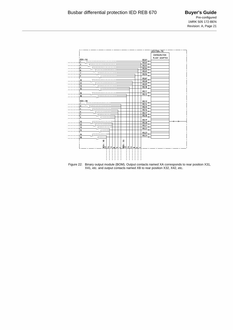
Figure 22: Binary output module (BOM). Output contacts named XA corresponds to rear position X31, X41, etc. and output contacts named XB to rear position X32, X42, etc.

Busbar differential protection IED REB 670 Buyer's GuidePre-configured
1MRK 505 172-BENRevision: A, Page 22
Technical data General
Definitions
Energizing quantities, rated values and limits
Analog inputsTable 4: TRM - Energizing quantities, rated values and limits
Auxiliary DC voltageTable 5: PSM - Power supply module
Binary inputs and outputsTable 6: BIM - Binary input module
Table 7: BIM - Binary input module with enhanced pulse counting capabilities
Reference value:The specified value of an influencing factor to which are referred the characteristics of the equipment.Nominal range:The range of values of an influencing quantity (factor) within which, under specified conditions, the equipment meets the specified requirements.Operative range:The range of values of a given energizing quantity for which the equipment, under specified conditions, is able to perform its intended functions according to the specified requirements.
Quantity Rated value Nominal rangeCurrent Ir = 1 or 5 A (0.2-40) × IrOperative range (0.02-100) x IrPermissive overload 4 × Ir cont.
100 × Ir for 1 s *)
Frequency fr = 50/60 Hz ± 5%*) max. 350 A for 1 s when COMBITEST test switch is included.
Quantity Rated value Nominal rangeAuxiliary dc voltage, EL (input) EL = (24 - 60) V
EL = (90 - 250) VEL ± 20%EL ± 20%
Power consumption 50 W typically -Auxiliary DC power in-rush < 5 A during 0.1 s -
Quantity Rated value Nominal rangeBinary inputs 16 -DC voltage, RL RL24 (24/40) V
RL48 (48/60) VRL110 (110/125) VRL220 (220/250) V
RL ± 20%RL ± 20%RL ± 20% RL ± 20%
Power consumptionRL24 = (24/40) VRL48 = (48/60) VRL110 = (110/125) VRL220 = (220/250) V
max. 0.05 W/inputmax. 0.1 W/inputmax. 0.2 W/inputmax. 0.4 W/input
-
Counter input frequency 10 pulses/s max -Oscillating signal discriminator Blocking settable 1–40 Hz
Release settable 1–30 Hz
Quantity Rated value Nominal rangeBinary inputs 16 -DC voltage, RL RL24 (24/40) V
RL48 (48/60) VRL110 (110/125) VRL220 (220/250) V
RL ± 20%RL ± 20%RL ± 20% RL ± 20%
Power consumptionRL24 = (24/40) VRL48 = (48/60) VRL110 = (110/125) VRL220 = (220/250) V
max. 0.05 W/inputmax. 0.1 W/inputmax. 0.2 W/inputmax. 0.4 W/input
-

Busbar differential protection IED REB 670 Buyer's GuidePre-configured
1MRK 505 172-BENRevision: A, Page 23
Table 8: IOM - Binary input/output module
Table 9: IOM - Binary input/output module contact data (reference standard: IEC 61810-2)
Table 10: BOM - Binary output module contact data (reference standard: IEC 61810-2)
Influencing factorsTable 11: Temperature and humidity influence
Counter input frequency 10 pulses/s max -Balanced counter input frequency 40 pulses/s max -Oscillating signal discriminator Blocking settable 1–40 Hz
Release settable 1–30 Hz
Quantity Rated value Nominal rangeBinary inputs 8 -DC voltage, RL RL24 = (24/40) V
RL48 = (48/60) VRL110 = (110/125) VRL220 = (220/250) V
RL ± 20%RL ± 20%RL ± 20%RL ± 20%
Power consumptionRL24 = (24/40) VRL48 = (48/60) VRL110 = (110/125) VRL220 = (220/250) V
max. 0.05 W/inputmax. 0.1 W/inputmax. 0.2 W/inputmax. 0.4 W/input
-
Function or quantity Trip and signal relays Fast signal relays (parallel reed relay)Binary outputs 10 2Max system voltage 250 V AC, DC 250 V AC, DCTest voltage across open contact, 1 min 1000 V rms 800 V DCCurrent carrying capacityContinuous1 s
8 A10 A
8 A10 A
Making capacity at inductive load with L/R>10 ms0.2 s1.0 s
30 A10 A
0.4 A0.4 A
Breaking capacity for AC, cos ϕ > 0.4 250 V/8.0 A 250 V/8.0 ABreaking capacity for DC with L/R < 40 ms
48 V/1 A110 V/0.4 A220 V/0.2 A250 V/0.15 A
48 V/1 A110 V/0.4 A220 V/0.2 A250 V/0.15 A
Maximum capacitive load - 10 nF
Function or quantity Trip and Signal relaysBinary outputs 24Max system voltage 250 V AC, DCTest voltage across open contact, 1 min 1000 V rmsCurrent carrying capacityContinuous1 s
8 A10 A
Making capacity at inductive load with L/R>10 ms0.2 s1.0 s
30 A10 A
Breaking capacity for AC, cos ϕ>0.4 250 V/8.0 ABreaking capacity for DC with L/R < 40 ms 48 V/1 A
110 V/0.4 A220 V/0.2 A250 V/0.15 A
Quantity Rated value Nominal range
Parameter Reference value Nominal range InfluenceAmbient temperature, oper-ate value
+20 °C -10 °C to +55 °C 0.02% /°C
Relative humidityOperative range
10%-90%0%-95%
10%-90% -
Storage temperature -40 °C to +70 °C - -

Busbar differential protection IED REB 670 Buyer's GuidePre-configured
1MRK 505 172-BENRevision: A, Page 24
Table 12: Auxiliary DC supply voltage influence on functionality during operation
Table 13: Frequency influence (reference standard: IEC 60255–6)
Type tests according to standardsTable 14: Electromagnetic compatibility
Table 15: Insulation
Table 16: Environmental tests
Dependence on Reference value Within nominal range InfluenceRipple, in DC auxiliary voltageOperative range
max. 2%Full wave rectified
12% of EL 0.01% /%
Auxiliary voltage dependence, operate value ± 20% of EL 0.01% /%Interrupted auxiliary DC voltage 24-60 V DC ± 20%
90-250 V DC ± 20%Interruption interval
0–50 ms No restart0–∞ s Correct behaviour at
power downRestart time <140 s
Dependence on Within nominal range InfluenceFrequency dependence, operate value fr ± 2.5 Hz for 50 Hz
fr ± 3.0 Hz for 60 Hz± 1.0% / Hz
Frequency dependence for differential protection
fr ± 2.5 Hz for 50 Hzfr ± 3.0 Hz for 50 Hz
± 2.0% / Hz
Harmonic frequency dependence (20% content)
2nd, 3rd and 5th harmonic of fr ± 1.0%
Harmonic frequency dependence for differential protection (10% content)
2nd, 3rd and 5th harmonic of fr ± 6.0%
Test Type test values Reference standards1 MHz burst disturbance 2.5 kV IEC 60255-22-1, Class III100 kHz disturbance 2.5 kV IEC 61000-4-12, Class IIIElectrostatic dischargeDirect applicatonIndirect application
15 kV air discharge8 kV contact discharge8 kV contact discharge
IEC 60255-22-2, Class IV
IEC 61000-4-2, Class IVFast transient disturbance 4 kV IEC 60255-22-4, Class ASurge immunity test 1-2 kV, 1.2/50 μs
high energyIEC 60255-22-5
Power frequency immunity test 150-300 V, 50 Hz
IEC 60255-22-7, Class A
Power frequency magnetic field test 1000 A/m, 3 s IEC 61000-4-8, Class VRadiated electromagnetic field disturbance 20 V/m, 80-1000 MHz IEC 60255-22-3Radiated electromagnetic field disturbance 20 V/m, 80-2500 MHz EN 61000-4-3Radiated electromagnetic field disturbance 35 V/m
26-1000 MHzIEEE/ANSI C37.90.2
Conducted electromagnetic field distur-bance
10 V, 0.15-80 MHz IEC 60255-22-6
Radiated emission 30-1000 MHz IEC 60255-25Conducted emission 0.15-30 MHz IEC 60255-25
Test Type test values Reference standardDielectric test 2.0 kV AC, 1 min. IEC 60255-5Impulse voltage test 5 kV, 1.2/50 μs, 0.5 JInsulation resistance >100 MΩ at 500 VDC
Test Type test value Reference standardCold test Test Ad for 16 h at -25°C IEC 60068-2-1Storage test Test Ad for 16 h at -40°C IEC 60068-2-1Dry heat test Test Bd for 16 h at +70°C IEC 60068-2-2Damp heat test, steady state Test Ca for 4 days at +40 °C and humidity
93%IEC 60068-2-3
Damp heat test, cyclic Test Db for 6 cycles at +25 to +55 °C and humidity 93 to 95% (1 cycle = 24 hours)
IEC 60068-2-30

Busbar differential protection IED REB 670 Buyer's GuidePre-configured
1MRK 505 172-BENRevision: A, Page 25
Table 17: CE compliance
Table 18: Mechanical tests
Differential protectionTable 19: Busbar differential protection (PDIF, 87B)
Current protectionTable 20: Four step phase overcurrent protection (POCM, 51/67)
Table 21: Four step single phase overcurrent protection (POCM, 51)
Test According toImmunity EN 61000-6-2Emissivity EN 61000-6-4Low voltage directive EN 50178
Test Type test values Reference standardsVibration Class I IEC 60255-21-1Shock and bump Class I IEC 60255-21-2Seismic Class I IEC 60255-21-3
Function Range or value AccuracyOperating characteristic S=0.53 fixed ± 2.0% of Ir for I < Ir
± 2.0% of I for I > IrReset ratio > 95% -Differential current operating level (1-100000) A ± 2.0% of Ir for I < Ir
± 2.0% of I for I > IrSensitive differential operation level (1-100000) A ± 2.0% of Ir for I < Ir
± 2.0% of I for I < IrCheck zone operation level (0-100000) A ± 2.0% of Ir for I < Ir
± 2.0% of I for I > IrCheck zone slope (0.0-0.9) -Timers (0.000-60.000) s ± 0.5% ± 10 msTimers (0.00-6000.00) s ± 0.5% ± 10 msOperate time 19 ms typically at 0 to 2 x Id
12 ms typically at 0 to 10 x Id-
Reset time 21 ms typically at 2 to 0 x Id29 ms typically at 10 to 0 x Id
-
Critical impulse time 8 ms typically at 0 to 2 x Id -
Function Setting range AccuracyOperate current (1-2500)% of lbase ± 1.0% of Ir at I ≤ Ir
± 1.0% of I at I > IrReset ratio > 95% -Min. operating current (1-100)% of lbase ± 1.0% of IrMaximum forward angle (40.0–70.0) degrees ± 2.0 degreesMinimum forward angle (75.0–90.0) degrees ± 2.0 degreesSecond harmonic blocking (5–100)% of fundamental ± 2.0% of IrIndependent time delay (0.000-60.000) s ± 0.5% ± 10 msMinimum operate time (0.000-60.000) s ± 0.5% ± 10 msInverse characteristics, see table 42 and table 43
19 curve types See table 42 and table 43
Operate time, start function 25 ms typically at 0 to 2 x Iset -Reset time, start function 25 ms typically at 2 to 0 x Iset -Critical impulse time 10 ms typically at 0 to 2 x Iset -Impulse margin time 15 ms typically -
Function Setting range AccuracyOperate current (1-2500)% of lbase ± 1.0% of Ir at I ≤ Ir
± 1.0% of I at I > IrReset ratio > 95% -Second harmonic blocking (5–100)% of fundamental ± 2.0% of IrIndependent time delay (0.000-60.000) s ± 0.5% ± 10 msMinimum operate time (0.000-60.000) s ± 0.5% ± 10 msInverse characteristics, see table 42 and table 43
19 curve types See table 42 and table 43
Operate time, start function 25 ms typically at 0 to 2 x Iset -

Busbar differential protection IED REB 670 Buyer's GuidePre-configured
1MRK 505 172-BENRevision: A, Page 26
Table 22: Breaker failure protection (RBRF, 50BF)
Table 23: Breaker failure protection, single phase version (RBRF, 50BF)
ControlTable 24: Autorecloser (RREC, 79)
Reset time, start function 25 ms typically at 2 to 0 x Iset -Critical impulse time 10 ms typically at 0 to 2 x Iset -Impulse margin time 15 ms typically -
Function Range or value AccuracyOperate phase current (5-200)% of lbase ± 1.0% of Ir at I ≤ Ir
± 1.0% of I at I > IrReset ratio, phase current > 95% -Operate residual current (2-200)% of lbase ± 1.0% of Ir at I ≤ Ir
± 1.0% of I at I > IrReset ratio, residual current > 95% -Phase current level for blocking of con-tact function
(5-200)% of lbase ± 1.0% of Ir at I ≤ Ir± 1.0% of I at I > Ir
Reset ratio > 95% -Timers (0.000-60.000) s ± 0.5% ± 10 msOperate time for current detection 10 ms typically -Reset time for current detection 15 ms maximum -
Function Range or value AccuracyOperate phase current (5-200)% of lbase ± 1.0% of Ir at I ≤ Ir
± 1.0% of I at I > IrReset ratio, phase current > 95% -Phase current level for blocking of con-tact function
(5-200)% of lbase ± 1.0% of Ir at I ≤ Ir± 1.0% of I at I > Ir
Reset ratio > 95% -Timers (0.000-60.000) s ± 0.5% ± 10 msOperate time for current detection 10 ms typically -Reset time for current detection 15 ms maximum -
Function Setting range Accuracy
Function Range or value AccuracyNumber of autoreclosing shots 1 - 5 -Number of autoreclosing programs 8 -Autoreclosing open time:shot 1 - t1 1Phshot 1 - t1 2Phshot 1 - t1 3PhHSshot 1 - t1 3PhDld
(0.000-60.000) s ± 0.5% ± 10 ms
shot 2 - t2shot 3 - t3shot 4 - t4shot 5 - t5
(0.00-6000.00) s
Extended autorecloser open time (0.000-60.000) sAutorecloser maximum wait time for sync (0.00-6000.00) sMaximum trip pulse duration (0.000-60.000) sInhibit reset time (0.000-60.000) sReclaim time (0.00-6000.00) sMinimum time CB must be closed before AR becomes ready for autoreclosing cycle
(0.00-6000.00) s
Circuit breaker closing pulse length (0.000-60.000) sCB check time before unsuccessful (0.00-6000.00) sWait for master release (0.00-6000.00) sWait time after close command before pro-ceeding to next shot
(0.000-60.000) s
Busbar differential protection IED REB 670 Buyer's GuidePre-configured
1MRK 505 172-BENRevision: A, Page 27
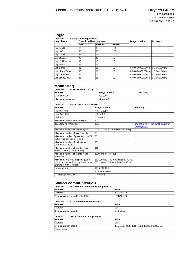
LogicTable 25: Configurable logic blocks
MonitoringTable 26: Event counter (GGIO)
Table 27: Disturbance report (RDRE)
Station communicationTable 28: IEC 61850-8-1 communication protocol
Table 29: LON communication protocol
Table 30: SPA communication protocol
Logic block Quantity with update rate Range or value Accuracyfast medium normal
LogicAND 90 90 100 - -LogicOR 90 90 100 - -LogicXOR 15 15 10 - -LogicInverter 45 45 50 - -LogicSRMemory 15 15 10 - -LogicGate 15 15 10 - -LogicTimer 15 15 10 (0.000–90000.000) s ± 0.5% ± 10 msLogicPulseTimer 15 15 10 (0.000–90000.000) s ± 0.5% ± 10 msLogicTimerSet 15 15 10 (0.000–90000.000) s ± 0.5% ± 10 msLogicLoopDelay 15 15 10 (0.000–90000.000) s ± 0.5% ± 10 ms
Function Range or value AccuracyCounter value 0-10000 -Max. count up speed 10 pulses/s -
Function Range or value AccuracyPre-fault time (0.05–0.30) s -Post-fault time (0.1–5.0) s -Limit time (0.5–6.0) s -Maximum number of recordings 100 -Time tagging resolution 1 ms See Table 41: "Time synchronization,
time tagging".Maximum number of analog inputs 30 + 10 (external + internally derived) -Maximum number of binary inputs 96 -Maximum number of phasors in the Trip Value recorder per recording
30 -
Maximum number of indications in a disturbance report
96 -
Maximum number of events in the Event recording per recording
150 -
Maximum number of events in the Event list
1000, first in - first out -
Maximum total recording time (3.4 s recording time and maximum number of channels, typical value)
340 seconds (100 recordings) at 50 Hz, 280 seconds (80 recordings) at 60 Hz
-
Sampling rate 1 kHz at 50 Hz1.2 kHz at 60 Hz
-
Recording bandwidth (5-300) Hz -
Function ValueProtocol IEC 61850-8-1Communication speed for the IEDs 100BASE-FX
Function ValueProtocol LONCommunication speed 1.25 Mbit/s
Function ValueProtocol SPACommunication speed 300, 1200, 2400, 4800, 9600, 19200 or 38400 BdSlave number 1 to 899

Busbar differential protection IED REB 670 Buyer's GuidePre-configured
1MRK 505 172-BENRevision: A, Page 28
Table 31: IEC 60870-5-103 communication protocol
Table 32: SLM – LON port
Table 33: SLM – SPA/IEC 60870-5-103 port
Remote communicationTable 34: Line data communication module (LDCM)
Hardware
IEDTable 35: Case
Table 36: Water and dust protection level according to IEC 60529
Table 37: Weight
Connection systemTable 38: CT circuit connectors
Function ValueProtocol IEC 60870-5-103Communication speed 9600, 19200 Bd
Quantity Range or valueOptical connector Glass fibre: type ST
Plastic fibre: type HFBR snap-inFibre, optical budget Glass fibre: 11 dB (1000 m typically *)
Plastic fibre: 7 dB (10 m typically *)Fibre diameter Glass fibre: 62.5/125 μm
Plastic fibre: 1 mm*) depending on optical budget calculation
Quantity Range or valueOptical connector Glass fibre: type ST
Plastic fibre: type HFBR snap-inFibre, optical budget Glass fibre: 11 dB (1000 m typically *)
Plastic fibre: 7 dB (25 m typically *)Fibre diameter Glass fibre: 62.5/125 μm
Plastic fibre: 1 mm*) depending on optical budget calculation
Quantity Range or valueType of fibre Graded-index multimode 62.5/125 μm or 50/125 μmWave length 820 nmOptical budgetGraded-index multimode 62.5/125 μmGraded-index multimode 50/125 μm
13 dB (typical distance 3 km *)9 dB (typical distance 2 km *)
Optical connector Type STProtocol C37.94Data transmission SynchronousTransmission rate 64 kbit/sClock source Internal or derived from received signal*) depending on optical budget calculation
Material Steel sheetFront plate Steel sheet profile with cut-out for HMISurface treatment Aluzink preplated steelFinish Light grey (RAL 7035)
Front IP40 (IP54 with sealing strip)Rear, sides, top and bottom IP20
Case size Weight6U, 1/2 x 19” ≤ 10 kg6U, 1/1 x 19” ≤ 18 kg
Connector type Rated voltage and current Maximum conductor areaTerminal blocks of feed through type 250 V AC, 20 A 4 mm2

Busbar differential protection IED REB 670 Buyer's GuidePre-configured
1MRK 505 172-BENRevision: A, Page 29
Table 39: Binary I/O connection system
Basic IED functionsTable 40: Self supervision with internal event list
Table 41: Time synchronization, time tagging
Inverse characteristicsTable 42: Inverse time characteristics ANSI
Table 43: Inverse time characteristics IEC
Connector type Rated voltage Maximum conductor areaScrew compression type 250 V AC 2.5 mm2
2 × 1 mm2
Data ValueRecording manner Continuous, event controlledList size 1000 events, first in-first out
Function ValueTime tagging resolution, Events and Sampled Measurement Values
1 ms
Time tagging error with synchronization once/min (minute pulse synchronization), Events and Sampled Measurement Values
± 1.0 ms typically
Time tagging error with SNTP synchronization, Sampled Measurement Values
± 1.0 ms typically
Function Range or value AccuracyOperate characteristic:
Reset characteristic:
I = Imeasured/Iset
k = 0.05-999 in steps of 0.01 unless otherwise stated
-
ANSI Extremely Inverse no 1 A=28.2, B=0.1217, P=2.0, tr=29.1
ANSI/IEEE C37.112, class 5 + 30 ms
ANSI Very inverse no 2 A=19.61, B=0.491, P=2.0, tr=21.6
ANSI Normal Inverse no 3 A=0.0086, B=0.0185, P=0.02, tr=0.46
ANSI Moderately Inverse no 4 A=0.0515, B=0.1140, P=0.02, tr=4.85
ANSI Long Time Extremely Inverse no 6 A=64.07, B=0.250, P=2.0, tr=30ANSI Long Time Very Inverse no 7 A=28.55, B=0.712, P=2.0,
tr=13.46ANSI Long Time Inverse no 8 k=(0.01-1.20) in steps of 0.01
A=0.086, B=0.185, P=0.02, tr=4.6
Function Range or value AccuracyOperate characteristic:
I = Imeasured/Iset
k = (0.05-1.10) in steps of 0.01 -
Time delay to reset, IEC inverse time (0.000-60.000) s ± 0.5% of set time ± 10 ms
( )1= + ⋅
−
⎛ ⎞⎜ ⎟⎜ ⎟⎝ ⎠
P
At B k
I
( )2 1= ⋅
−
trt kI
( )1= ⋅
−
⎛ ⎞⎜ ⎟⎜ ⎟⎝ ⎠
P
At k
I
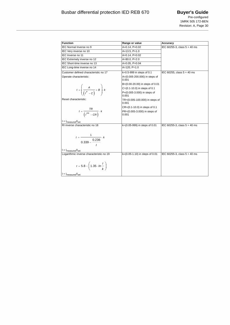
Busbar differential protection IED REB 670 Buyer's GuidePre-configured
1MRK 505 172-BENRevision: A, Page 30
IEC Normal Inverse no 9 A=0.14, P=0.02 IEC 60255-3, class 5 + 40 msIEC Very inverse no 10 A=13.5, P=1.0IEC Inverse no 11 A=0.14, P=0.02IEC Extremely inverse no 12 A=80.0, P=2.0IEC Short-time inverse no 13 A=0.05, P=0.04IEC Long-time inverse no 14 A=120, P=1.0
Customer defined characteristic no 17Operate characteristic:
Reset characteristic:
I = Imeasured/Iset
k=0.5-999 in steps of 0.1A=(0.005-200.000) in steps of 0.001B=(0.00-20.00) in steps of 0.01C=(0.1-10.0) in steps of 0.1P=(0.005-3.000) in steps of 0.001TR=(0.005-100.000) in steps of 0.001CR=(0.1-10.0) in steps of 0.1PR=(0.005-3.000) in steps of 0.001
IEC 60255, class 5 + 40 ms
RI inverse characteristic no 18
I = Imeasured/Iset
k=(0.05-999) in steps of 0.01 IEC 60255-3, class 5 + 40 ms
Logarithmic inverse characteristic no 19
I = Imeasured/Iset
k=(0.05-1.10) in steps of 0.01 IEC 60255-3, class 5 + 40 ms
Function Range or value Accuracy
( )= + ⋅
−
⎛ ⎞⎜ ⎟⎜ ⎟⎝ ⎠
P
At B k
I C
( )= ⋅
−PR
TRt k
I CR
1
0.2360.339
= ⋅
−
t k
I
5.8 1.35= − ⋅⎛ ⎞⎜ ⎟⎝ ⎠
tI
Ink

Busbar differential protection IED REB 670 Buyer's GuidePre-configured
1MRK 505 172-BENRevision: A, Page 31
Ordering REB 670, Busbar differential protection IED
GuidelinesCarefully read and follow the set of rules to ensure problem-free order management. Please refer to the function matrix for included software functions given in each software option package. Please observe that the character length of the software option section varies depending on the included options.Enter option codes in the shaded spaces to complete the ordering number. To obtain the complete ordering code, please combined code from sheet 1 and sheet 2, as given in the example below. 1 BIM and 1 BOM in A20, A31, B20 and 2 BIM and 1 BOM in B21, B31 is basic. Order futher I/O as required.
Sheet 1 Sheet 2REB 670* - - - - - - -
SOFTWARE Notes and RulesVersion number
Latest version XXVersion No 1.0
Configuration alternatives3 phase, 4 bays A203 phase, 8 bays A311 phase, 12 bays, 1/2 19” case B201 phase, 12 bays, 1/1 19” case B211 phase, 24 bays B31
CAP configurationSimple station layout, 1 1/2CB, 2CB, 1CB, b-contacts, PDIF only
X01
Double bus-single breaker, a and b contacts, PDIF only
X02 Note: Only for A31, B21 and B31
Double bus-single breaker, a and b contacts, PDIF, RBRF and POCM
X03 Note: Only for A31, B21 and B31
Software options All fields in the ordering form do not need to be filled inNo option X00Four step phase overcurrent protection, 4 bays C06 Note: Only for A20Four step phase overcurrent protection, 8 bays C07 Note: Only for A31Four step single phase overcurrent protection, 12 bays
C08 Note: Only for B20 and B21
Four step single phase overcurrent protection, 24 bays
C09 Note: Only for B31
Breaker failure protection, 4 bays C10 Note: Only for A20Breaker failure protection, 8 bays C11 Note: Only for A31Breaker failure protection, 12 bays, single phase
C12 Note: Only for B20 and B21
Breaker failure protection, 24 bays, single phase
C13 Note: Only for B31
Autorecloser, 2 circuit breakers H05Additional HMI language
No second HMI language X0German A1Russian A2French A3Spanish A4Italian A5Polish A6Hungarian A7Czech A8Swedish A9
Casing1/2 19” case A Must be used for A20 and B201/1 19” case 2TRM slots E Must be used for A31, B21 and B31
Mounting details with IP40 of protection from the front19” rack mounting kit for 1/2 19” case or 2xRHGS6 or RHGS12
A
19” rack mounting kit for 1/1 19” case CWall mounting kit DFlush mounting kit EFlush mounting kit + IP54 mounting seal F
Auxiliary power supply24-60 VDC A90-250 VDC B
Human machine interfaceSmall size - text AMedium size B

Busbar differential protection IED REB 670 Buyer's GuidePre-configured
1MRK 505 172-BENRevision: A, Page 32
Sheet 1 (Enter option codes from sheet 1 in spaces below) Sheet 2REB 670* - - - - - - - - - * A - -
Analog system (First module X401, second module X411)First Transformer input module, 12I, 1A A1First Transformer input module, 12, 5A A2No second TRM included X0 Note: 2 TRM only in A31 and B31Second Transformer input module, 12I, 1A A1Second Transformer input module, 12I, 5A A2
Binary input and output, mA and time synchronizating boards. Note! Basic 1 BIM and 1 BOM included.Slot position (rear view) Note! Max 3 positins in 1/2 rack
and 11 in 1/1 rack with 2 TRM and 14 in 1/1 rack wiht 1 TRM
-
X31
X41
X51
X61
X71
X81
X91
X10
1
X11
1
X12
1
X13
1 - -
1/2 Case with 1 TRM (A20 and B20) Note! Only for A30 and B30. Only position X31 to X51 can be selected
1/1 Case with 2 TRMNo board in this slot X X X X X X X X XBinary output module 24 output relays (BOM)
Note! Maximum 4 BOM boardsNote! Basic configuration in A20, A31 and B20 adapted for 1BIM and 1 BOMNote! Basic configuration in B21and B31 adapted for 2 BIM and 1 BOM
A A A A A A A A A A Note! Not in B21/B31
BIM 16 inputs, RL24-30 VDC B B B B B B B B B BBIM 16 inputs, RL48-60 VDC C C C C C C C C C CBIM 16 inputs, RL110-125 VDC D D D D D D D D D DBIM 16 inputs, RL220-250 VDC E E E E E E E E E EBIMp 16 inputs, RL24-30 VDC for pulse counting
F F F F F F F F F
BIMp 16 inputs, RL48-60 VDC for pulse counting
G G G G G G G G G
BIMp 16 inputs, RL110-125 VDC for pulse counting
H H H H H H H H H
BIMp 16 inputs, RL220-250 VDC for pulse counting
K K K K K K K K K
IOM 8 inputs, 10+2 output, RL24-30 VDC L L L L L L L L LIOM 8 inputs, 10+2 output, RL48-60 VDC M M M M M M M M MIOM 8 inputs, 10+2 output, RL110-125 VDC
N N N N N N N N N
IOM 8 inputs, 10+2 output, RL220-250 VDC
P P P P P P P P P
GPS on GCM card (in last slot) S SSerial communication unit for remote end communicationSlot position (rear view)
X31
2
X31
3No remote communication board included
X X
C37.94 single channel 3 km A ASerial communication unit for station communicationSlot position (rear view)
X30
1
X31
1
No first communication board included XNo second communication board included
X
Serial SPA/IEC 60870-5-103 and LON communication module (plastic)
A
Serial SPA /IEC 60870-5-103 (plastic) and LON (glass) communication module
B
Serial SPA/IEC 60870-5-103 and LON communication module (glass)
C
Optical ethernet module, 1 channel glass DOptical ethernet module, 2 channel glass E
Example:REB 670*1.0-A20X01-C06C10-X0-A-A-B-A-A1-X0-DAX-XX-XD

Busbar differential protection IED REB 670 Buyer's GuidePre-configured
1MRK 505 172-BENRevision: A, Page 33
Accessories
External current transformer unit
GPS antenna and mounting details
Test switchThe test system COMBITEST intended for use with the IED670 products is described in 1MRK 512 001-BEN and 1MRK 001024-CA. Please refer to the website www.abb.com/substationautomation and ABB Product Guide > High Voltage Products > Protection and Control > Modular Relay > Test Equipment for detailed information
Due to the high flexibility of our product and the wide variety of applications possible the test switches needs to be selected for each specific application.
Select your suitable test switch based on the avail-able contacts arrangements shown in the reference documentation.
However our proposal for suitable variants are:
RK926 315-CA is provided with four three-phase CT inputs with current shorting and with six trip output blocking contacts. It is suitable when inter-nal CT earthing is acceptable both for the three-phase version and single-phase versions. When more than four feeders are available or
expected in future several test switches are required and tripping must be blocked either by series connection of the trip test switch contacts, and/or blocking of tripping with the input contact 29-30 and configuration logic.
RK926 315- AV is provided with one three-phase CT input with current shorting and with sixteen trip output blocking contacts. It is suitable when external CT earthing is required both for the three-phase version and single-phase versions. One such switch is then used per bay. With such arrangement the best possible test facilities for BBP & integrated BFP are available
Test switches type RTXP 24 are ordered sepa-rately. Please refer to Section "Related documents" for reference to corresponding documents.
RHGS 6 Case or RHGS 12 Case with mounted RTXP 24 and the on/off switch for dc-supply are ordered separately. Please refer to Section "Related documents" for reference to corresponding docu-ments.
Mounting details
3 pcs SLCE 8–1 summation transformers on apparatus plate (2U high), 1/1 A
Quantity: 1MRK 000 643-EA
3 pcs SLCE 8–1 summation transformers on apparatus plate (2U high), 5/1 A
Quantity: 1MRK 000 643-FA
3 pcs SLCE 8–1 summation transformers on apparatus plate (2U high), 2/1 A
Quantity: 1MRK 000 643-GA
GPS antenna, including mounting kits
Quantity: 1MRK 001 640-AA
Cable for antenna, 20 m
Quantity: 1MRK 001 665-AA
Cable for antenna, 40 m
Quantity: 1MRK 001 665-BA
19” rack mounting kit for one test switch
Quantity: 1MRK 002 420-BE
19” rack mounting kit for two test switches
Quantity: 1MRK 002 420-BB

Busbar differential protection IED REB 670 Buyer's GuidePre-configured
1MRK 505 172-BENRevision: A, Page 34
Protection cover
Combiflex
Configuration and monitoring tools
Manuals
Protective cover for rear side of RHGS6, 6U, 1/4 x 19”
Quantity: 1MRK 002 420-AE
Protective cover for rear side of IED, 6U, 3/4 x 19”
Quantity: 1MRK 002 420-AB
Protective cover for rear side of IED, 6U, 1/1 x 19”
Quantity: 1MRK 002 420-AA
Key switch for lock-out of settings via LCD-HMI
Quantity: 1MRK 000 611-A
Note: To connect the key switch, leads with 10 A Combiflex socket on one end must be used.
Side-by-side mounting kit
Quantity: 1MRK 002 420-Z
Front connection cable between LCD-HMI and PC
Quantity: 1MRK 001 665-CA
LED Label special paper A4, 1 pc
Quantity: 1MRK 002 038-CA
LED Label special paper Letter, 1 pc
Quantity: 1MRK 002 038-DA
Protection and control IED manager PCM 600PCM 600 ver. 1.1, IED Manager
Quantity: 1MRK 003 395-AA
PCM 600 ver. 1.1, Engineering, IED Manager + CAP 531
Quantity: 1MRK 003 395-BA
PCM 600 ver. 1.1, Engineering Pro, IED Manager + CAP 531 + CCT for IEC 61850-8-1 configuration of IED
Quantity: 1MRK 003 395-CA
Note: One (1) IED Connect CD containing user documentation (Operator’s manual, Technical reference manual, Installa-tion and commissioning manual, Application manual and Getting started guide), Connectivity packages and LED label tem-plate is always included for each IED.
Rule: Specify additional quantity of IED Connect CD requested
Quantity: 1MRK 002 290-AA
Rule: Specify the number of printed manuals requestedOperator’s manual
Quantity: 1MRK 505 168-UENTechnical reference manual
Quantity: 1MRK 505 167-UEN

Busbar differential protection IED REB 670 Buyer's GuidePre-configured
1MRK 505 172-BENRevision: A, Page 35
Reference information
Sample specificationNumerical IED with differential, circuit breaker failure, end fault and overcurrent protection is intended for the selective, reliable and fast protec-tion of busbars, T-connections and meshed cor-ners. The IED shall be applicable for the protection of medium voltage (MV), high voltage (HV) and extra high voltage (EHV) installations at a power system frequency of 50Hz or 60Hz. The IED shall be able to detect all types of internal phase-to-phase and phase-to-ground faults in sol-idly grounded or low impedance grounded power systems, as well as all internal phase-to-phase faults in isolated or high-impedance grounded power systems. For power systems with limited earth fault current a sensitive differential protec-tion shall be available.
For all applications, it shall be possible to connect main CTs with different ratios (e.g 10:1) within the same differential protection zone. There shall be no requirements for any auxiliary CTs. Compensa-tion of different main CT ratios shall be achieved numerically by parameter settings.
The differential protection function shall have completely phase-segregated measurements. The typical operating time in case of internal faults shall be around 12 milliseconds, with guaranteed stability of the differential function for all external faults even with very high short-circuit currents and heavy CT saturation.
The IED shall include the ability to detect CT open circuit condition. No incorrect operation of the protection IED shall occur for CT open circuit condition and an alarm shall be issued to the super-visory system. Stability of the differential function must be guaranteed even for the case when only two feeders are connected to the zone of protection and then one of the two CTs is accidentally open circuited under full through-load condition. It shall be possible to reset the CT open circuit condition locally or remotely via the communication. Reset of the CT open circuit condition shall only be pos-sible if there is no differential current detected in the protected zone.
It shall be possible to engineer the complete busbar differential protection, zone selection logic, circuit
breaker failure and end fault protection scheme by using a graphical configuration tool. The graphical configuration tool shall be easy to use and intuitive for experienced protection engineers. It shall be possible to engineer the complete scheme includ-ing future extension feeders, such that at a latter stage they can be activated one by one. The inte-grated disconnector replica shall insure busbar dif-ferential protection and circuit breaker failure protection selective bay tripping. Disconnector and circuit breaker status supervision shall be pro-vided. Integrated overall check zone shall be avail-able in order to provide full busbar differential protection stability in case of completely wrong status indication of individual bay disconnectors. The facility to selectively block any integrated protection functions or alternatively to take a bay out of service shall be provided. Autoreclosing facility for delayed busbar restoration after busbar differential protection operation shall be available.
Comprehensive and continuous self-monitoring of the IED shall ensure no incorrect operations of the differential function in case of internal relay fail-ure. The front mounted, menu driven human-machine-interface shall display:
• Magnitude and phase angle of all individual bay currents per phase
• Magnitude of differential and total through-load currents for each phase and zone of protection
• Internal software connections between bay currents and individual zones
• Actual status of each primary switchgear object
• Tripping and open CT indications• Self supervision information
Integrated disturbance recorder and event list shall be available. Communication to the station control system via IEC 61850-8-1 and/or IEC 60870-5-103 shall be available.
Time synchronization of the internal real time clock via minute-pulse or alternatively via GPS shall be available.
Installation and commissioning manual
Quantity: 1MRK 505 169-UENApplication manual
Quantity: 1MRK 505 170-UENEngineering guide IED 670 products
Quantity: 1MRK 511 179-UEN
For our reference and statistics we would be pleased to be provided with the following application data:
Country: End user:
Station name: Voltage level: kV

Busbar differential protection IED REB 670 Buyer's GuidePre-configured
1MRK 505 172-BENRevision: A, Page 36
Related documents
Manufacturer
Documents related to REB 670 Identity numberOperator's manual 1MRK 505 168-UENInstallation and commissioning manual 1MRK 505 169-UENTechnical reference manual 1MRK 505 167-UENApplication manual 1MRK 505 170-UENBuyer's guide 1MRK 505 172-BEN
Connection and Installation components 1MRK 013 003-BENTest system, COMBITEST 1MRK 512 001-BENAccessories for IED 670 1MRK 514 012-BENGetting started guide IED 670 1MRK 500 065-UENSPA and LON signal list for IED 670 1MRK 500 075-WENIEC 61850 Data objects list for IED 670 1MRK 500 077-WENGeneric IEC 61850 IED Connectivity package 1KHA001027–UENProtection and Control IED Manager PCM 600 Installation sheet 1MRS755552Engineering guide IED 670 products 1MRK 511 179–UEN
Latest versions of the described documentation can be found on www.abb.com/substationautomation
ABB Power Technologies ABSubstation Automation ProductsSE-721 59 VästeråsSwedenTelephone: +46 (0) 21 34 20 00Facsimile: +46 (0) 21 14 69 18Internet: www.abb.com/substationautomation