

Metal Structures II Lecture III Crane supporting ...footbridge.pl/stud/z/se2/lec203.pdf · Photo:...
95
Metal Structures II Lecture III Crane supporting structures Loads
-
Upload
nguyenkhanh -
Category
Documents
-
view
218 -
download
1
Transcript of Metal Structures II Lecture III Crane supporting ...footbridge.pl/stud/z/se2/lec203.pdf · Photo:...
Metal Structures II
Lecture III
Crane supporting structures
Loads

Contents
Structure of lectures → #t / 3
General information about loads → #t / 4
Types of wheels → #t / 21
Loads and factors - values → #t / 27
Combinations of loads → #t / 82
Examination issues → #t / 93

Loads → Lecture #3
Beams: geometry of cross-section, resistance, instability prevention, local
effects, transverse stiffeners bumpers → Lecture #4
Beams: fatigue resistance, deformations; Columns: geometry of cross-section,
resistance, instability, deformations; Bracings → Lecture #5
Parts important for IInd design project
Structure of lectures
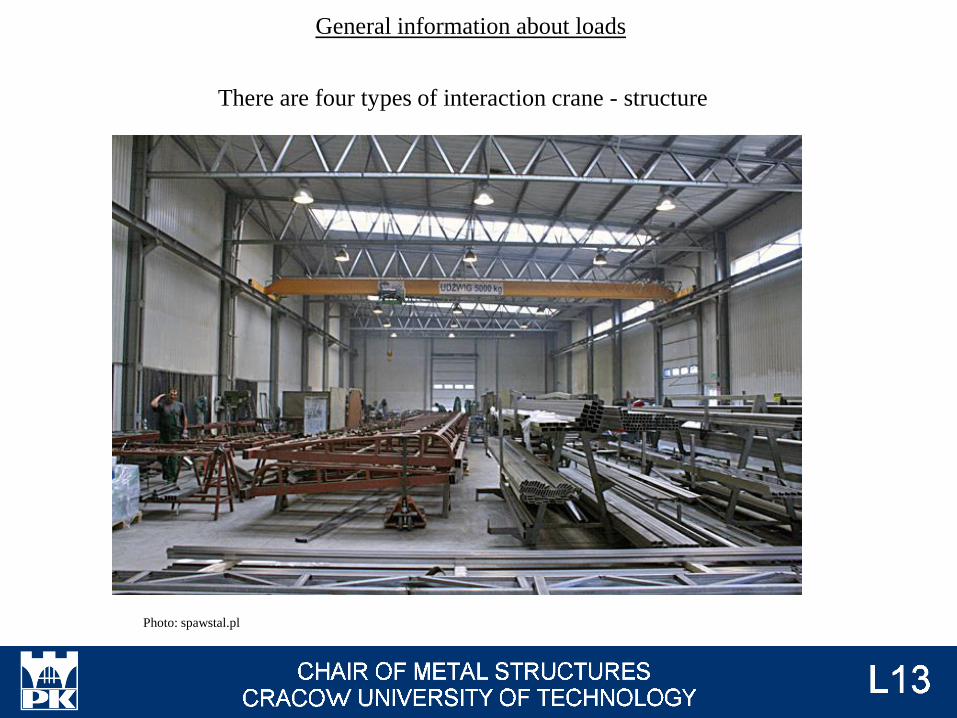
There are four types of interaction crane - structure
General information about loads
Photo: spawstal.pl
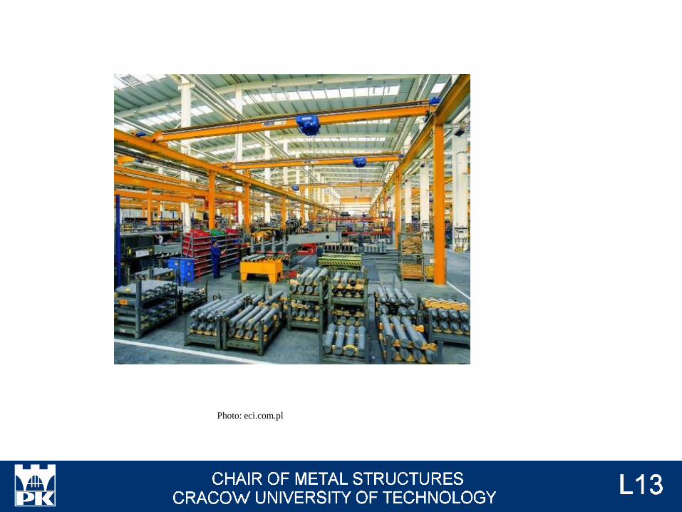
Photo: eci.com.pl
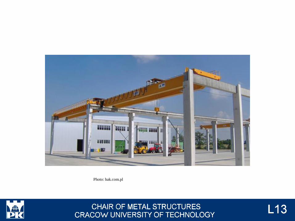
Photo: hak.com.pl
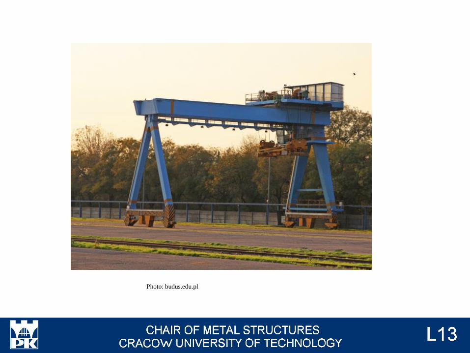
Photo: budus.edu.pl
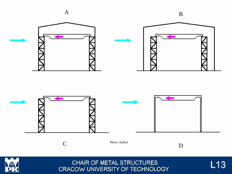
A B
C DPhoto: Author
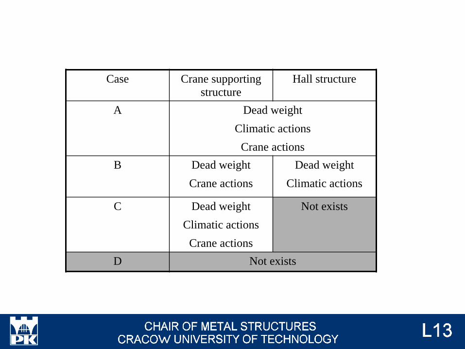
Case Crane supporting
structure
Hall structure
A Dead weight
Climatic actions
Crane actions
B Dead weight
Crane actions
Dead weight
Climatic actions
C Dead weight
Climatic actions
Crane actions
Not exists
D Not exists
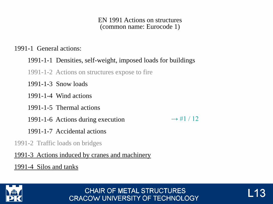
EN 1991 Actions on structures(common name: Eurocode 1)
1991-1 General actions:
1991-1-1 Densities, self-weight, imposed loads for buildings
1991-1-2 Actions on structures expose to fire
1991-1-3 Snow loads
1991-1-4 Wind actions
1991-1-5 Thermal actions
1991-1-6 Actions during execution
1991-1-7 Accidental actions
1991-2 Traffic loads on bridges
1991-3 Actions induced by cranes and machinery
1991-4 Silos and tanks
→ #1 / 12
Monorail hoist block
Overhead travelling crane:
underslung crane
top-mounted crane
There are three possibilities of loads from crane:
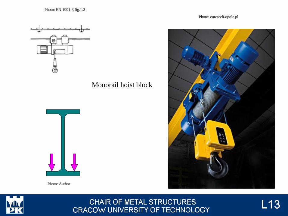
Monorail hoist block
Photo: eurotech-opole.pl
Photo: Author
Photo: EN 1991-3 fig.1.2
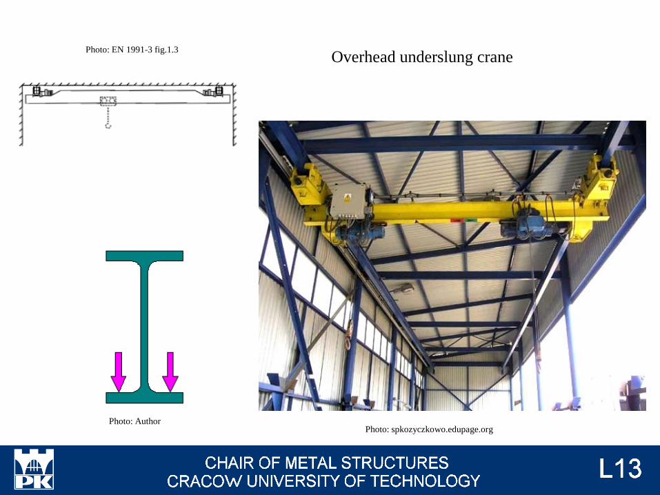
Overhead underslung crane
Photo: spkozyczkowo.edupage.orgPhoto: Author
Photo: EN 1991-3 fig.1.3
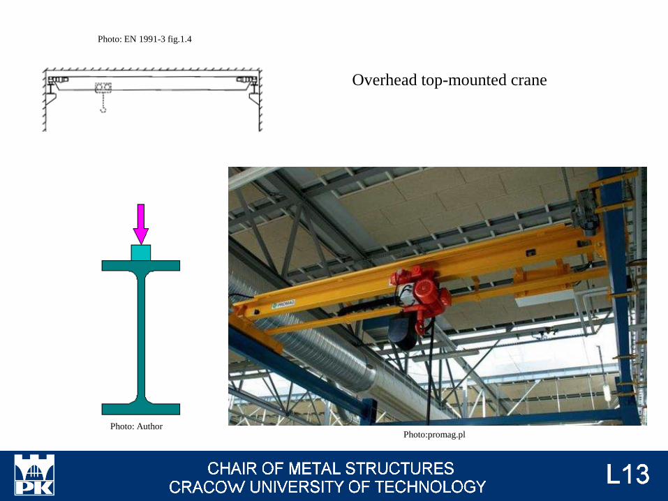
Overhead top-mounted crane
Photo:promag.plPhoto: Author
Photo: EN 1991-3 fig.1.4
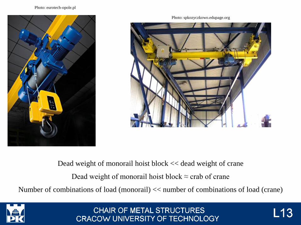
Dead weight of monorail hoist block << dead weight of crane
Dead weight of monorail hoist block ≈ crab of crane
Number of combinations of load (monorail) << number of combinations of load (crane)
Photo: eurotech-opole.pl
Photo: spkozyczkowo.edupage.org
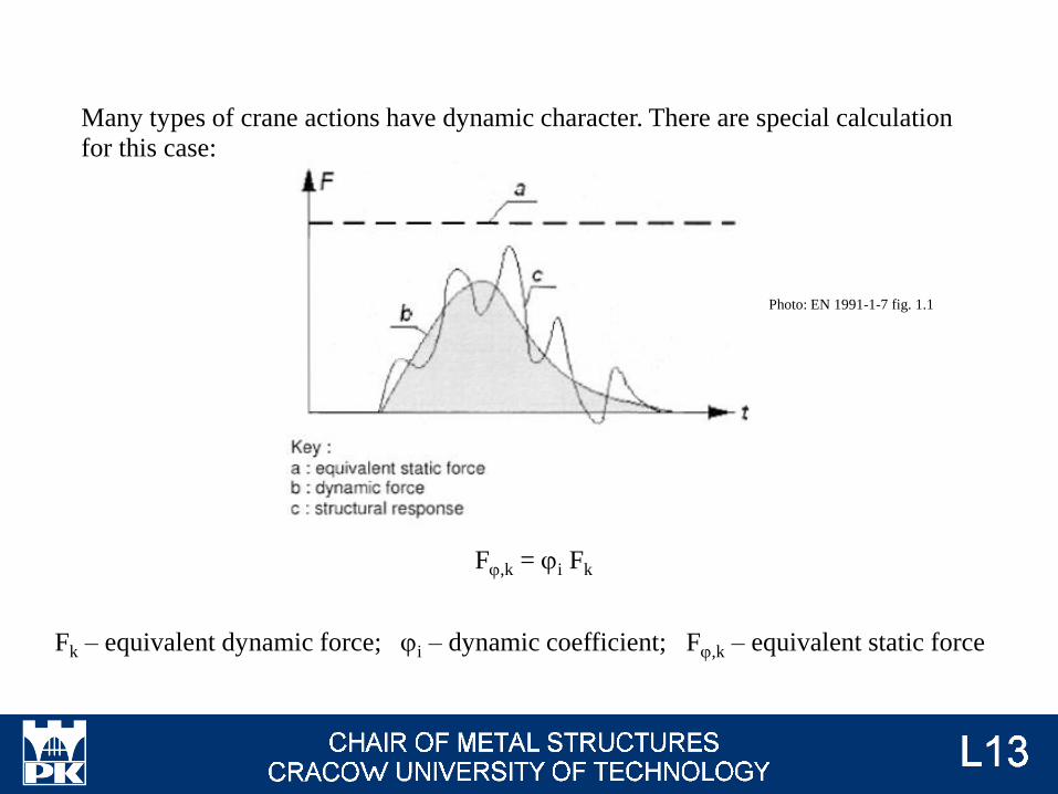
Fj,k = ji Fk
Fk – equivalent dynamic force; ji – dynamic coefficient; Fj,k – equivalent static force
Many types of crane actions have dynamic character. There are special calculation
for this case:
Photo: EN 1991-1-7 fig. 1.1
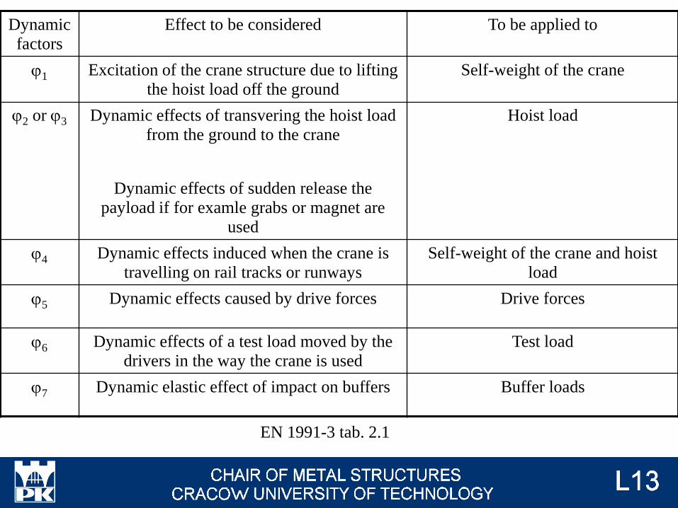
Dynamic
factors
Effect to be considered To be applied to
j1 Excitation of the crane structure due to lifting
the hoist load off the ground
Self-weight of the crane
j2 or j3 Dynamic effects of transvering the hoist load
from the ground to the crane
Dynamic effects of sudden release the
payload if for examle grabs or magnet are
used
Hoist load
j4 Dynamic effects induced when the crane is
travelling on rail tracks or runways
Self-weight of the crane and hoist
load
j5 Dynamic effects caused by drive forces Drive forces
j6 Dynamic effects of a test load moved by the
drivers in the way the crane is used
Test load
j7 Dynamic elastic effect of impact on buffers Buffer loads
EN 1991-3 tab. 2.1
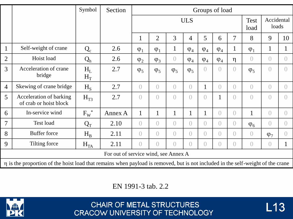
Symbol Section Groups of load
ULS Test
load
Accidental
loads
1 2 3 4 5 6 7 8 9 10
1 Self-weight of crane Qc 2.6 j1 j1 1 j4 j4 j4 1 j1 1 1
2 Hoist load Qh 2.6 j2 j3 0 j4 j4 j4 h 0 0 0
3 Acceleration of crane
bridgeHL
HT
2.7 j5 j5 j5 j5 0 0 0 j5 0 0
4 Skewing of crane bridge HS 2.7 0 0 0 0 1 0 0 0 0 0
5 Acceleration of barking
of crab or hoist blockHT3 2.7 0 0 0 0 0 1 0 0 0 0
6 In-service wind FW* Annex A 1 1 1 1 1 0 0 1 0 0
7 Test load QT 2.10 0 0 0 0 0 0 0 j6 0 0
8 Buffer force HB 2.11 0 0 0 0 0 0 0 0 j7 0
9 Tilting force HTA 2.11 0 0 0 0 0 0 0 0 0 1
For out of service wind, see Annex A
h is the proportion of the hoist load that remains when payload is removed, but is not included in the self-weight of the crane
EN 1991-3 tab. 2.2
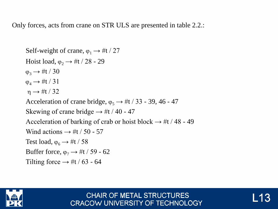
Only forces, acts from crane on STR ULS are presented in table 2.2.:
Self-weight of crane, j1 → #t / 27
Hoist load, j2 → #t / 28 - 29
j3 → #t / 30
j4 → #t / 31
h → #t / 32
Acceleration of crane bridge, j5 → #t / 33 - 39, 46 - 47
Skewing of crane bridge → #t / 40 - 47
Acceleration of barking of crab or hoist block → #t / 48 - 49
Wind actions → #t / 50 - 57
Test load, j6 → #t / 58
Buffer force, j7 → #t / 59 - 62
Tilting force → #t / 63 - 64
There are separated rules for monorail hoist block.
Additionally, there must be taken into consideration actions:
from workers on walkways, stairs, platforms and guardrails;
for FAT ULS;
for SLS.
Monorail hoist block → #t / 65
Workers activity → #t / 66
Fatigue actions → #t / 67 - 79
SLS → #t / 80
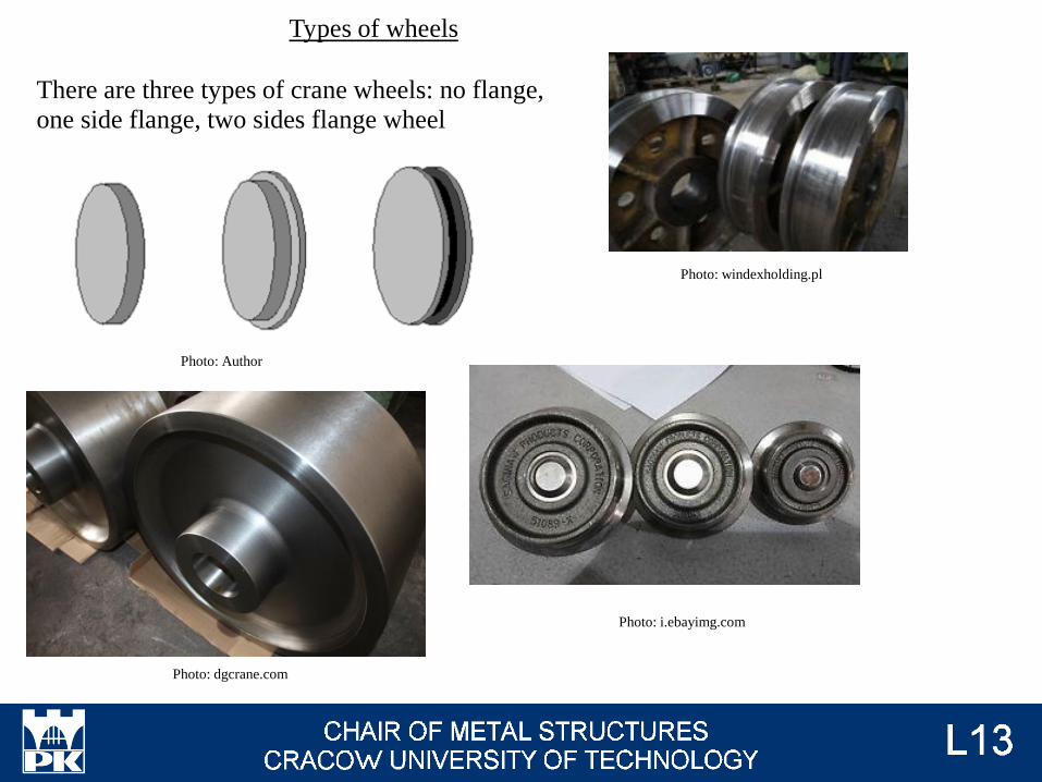
There are three types of crane wheels: no flange,
one side flange, two sides flange wheel
Photo: Author
Photo: dgcrane.com
Photo: i.ebayimg.com
Photo: windexholding.pl
Types of wheels
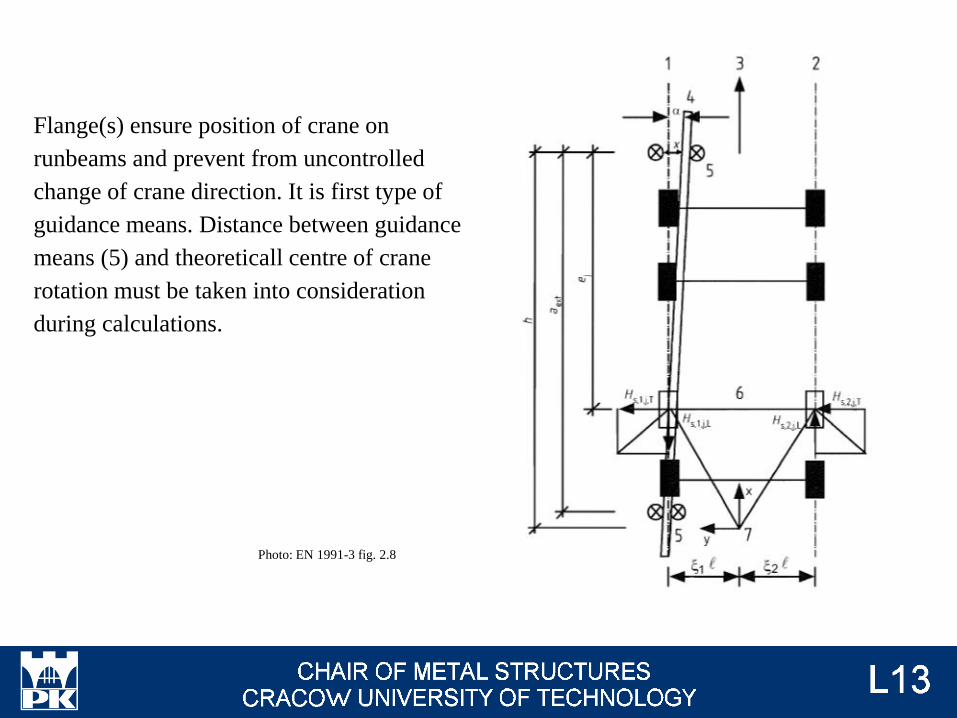
Photo: EN 1991-3 fig. 2.8
Flange(s) ensure position of crane on
runbeams and prevent from uncontrolled
change of crane direction. It is first type of
guidance means. Distance between guidance
means (5) and theoreticall centre of crane
rotation must be taken into consideration
during calculations.
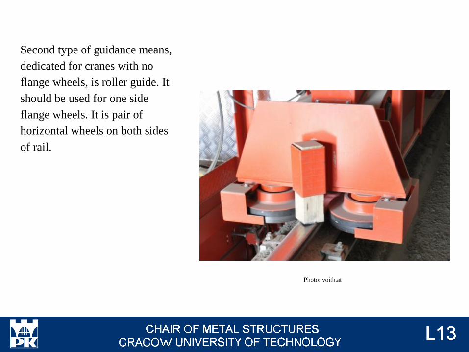
Photo: voith.at
Second type of guidance means,
dedicated for cranes with no
flange wheels, is roller guide. It
should be used for one side
flange wheels. It is pair of
horizontal wheels on both sides
of rail.
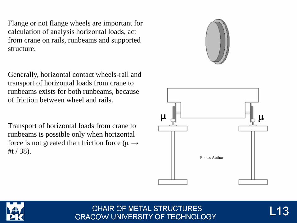
Flange or not flange wheels are important for
calculation of analysis horizontal loads, act
from crane on rails, runbeams and supported
structure.
Generally, horizontal contact wheels-rail and
transport of horizontal loads from crane to
runbeams exists for both runbeams, because
of friction between wheel and rails.
Transport of horizontal loads from crane to
runbeams is possible only when horizontal
force is not greated than friction force (m →
#t / 38).Photo: Author
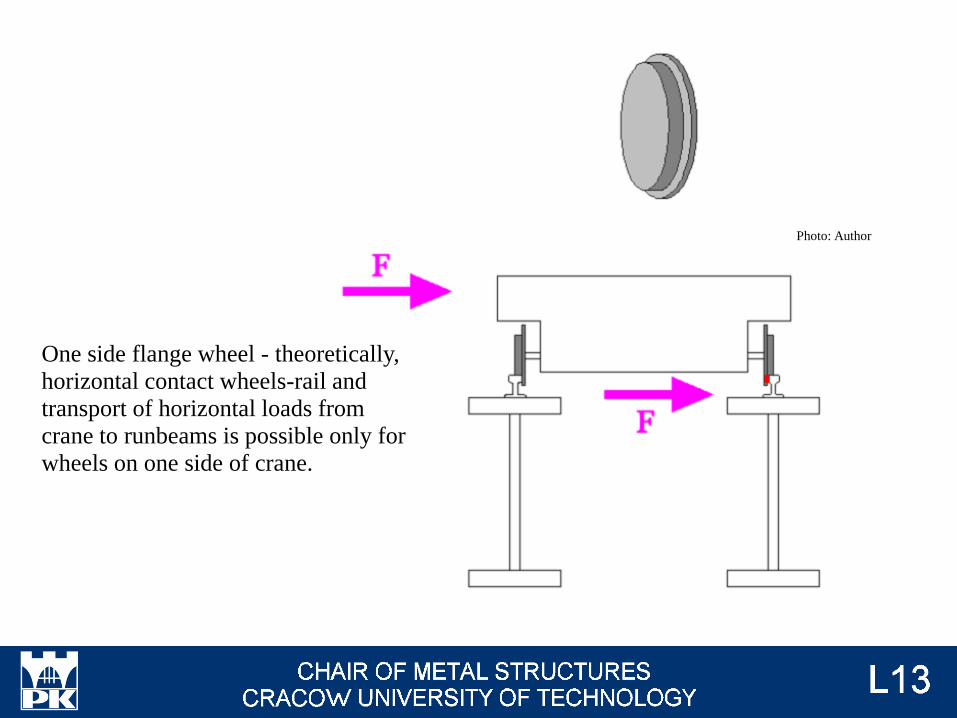
One side flange wheel - theoretically,
horizontal contact wheels-rail and
transport of horizontal loads from
crane to runbeams is possible only for
wheels on one side of crane.
Photo: Author
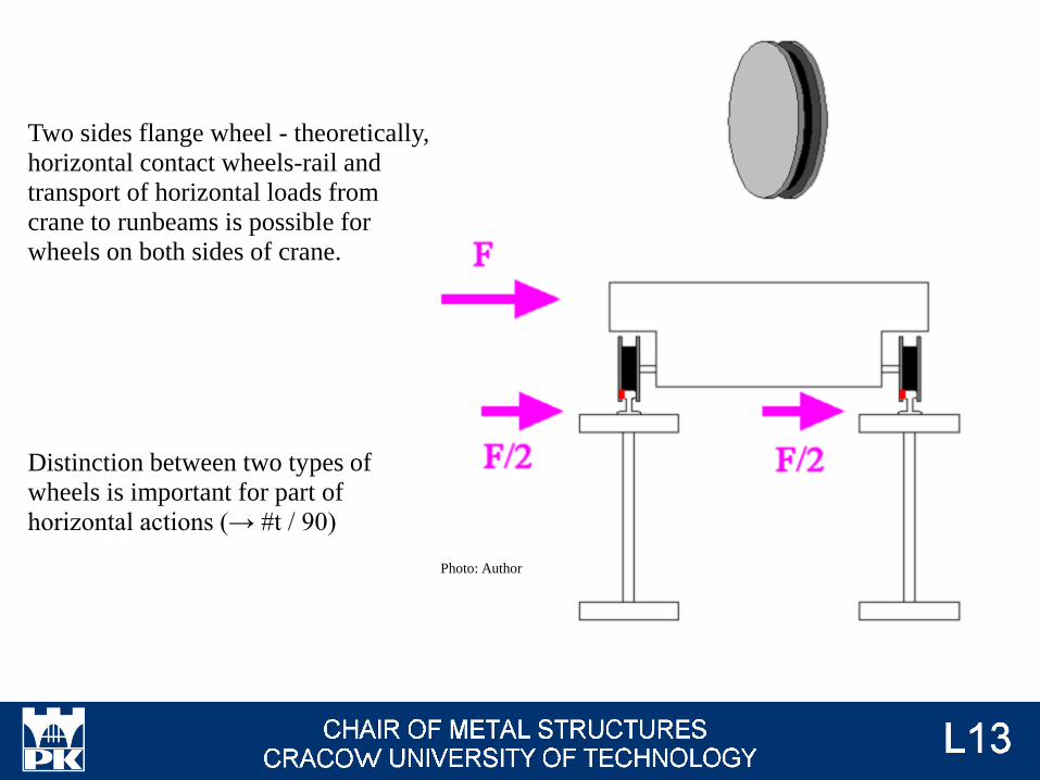
Two sides flange wheel - theoretically,
horizontal contact wheels-rail and
transport of horizontal loads from
crane to runbeams is possible for
wheels on both sides of crane.
Photo: Author
Distinction between two types of
wheels is important for part of
horizontal actions (→ #t / 90)
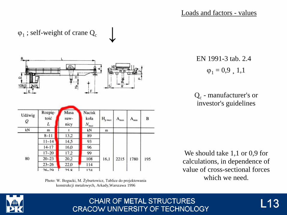
j1 ; self-weight of crane Qc
j1 = 0,9 ¸ 1,1
Qc - manufacturer's or
investor's guidelines
We should take 1,1 or 0,9 for
calculations, in dependence of
value of cross-sectional forces
which we need.
EN 1991-3 tab. 2.4
↓
Loads and factors - values
Photo: W. Bogucki, M. Żyburtowicz, Tablice do projektowania
konstrukcji metalowych, Arkady,Warszawa 1996
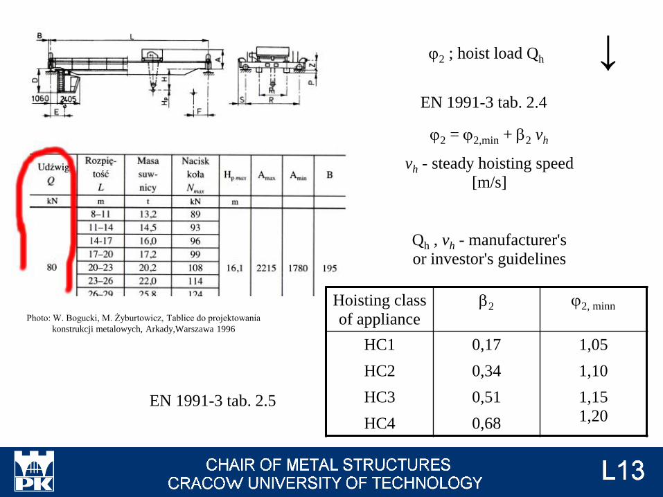
j2 = j2,min + b2 vh
vh - steady hoisting speed
[m/s]
Qh , vh - manufacturer's
or investor's guidelines
j2 ; hoist load Qh
EN 1991-3 tab. 2.4
EN 1991-3 tab. 2.5
↓
Photo: W. Bogucki, M. Żyburtowicz, Tablice do projektowania
konstrukcji metalowych, Arkady,Warszawa 1996
Hoisting class
of applianceb2 j2, minn
HC1
HC2
HC3
HC4
0,17
0,34
0,51
0,68
1,05
1,10
1,15
1,20

Hoisting class of appliance → EN 1991-3 Appendix B
...
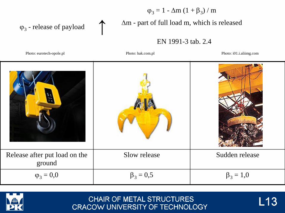
j3 = 1 - Dm (1 + b3) / m
Dm - part of full load m, which is released
Release after put load on the
ground
Slow release Sudden release
j3 = 0,0 b3 = 0,5 b3 = 1,0
j3 - release of payload
EN 1991-3 tab. 2.4
↑
Photo: eurotech-opole.pl Photo: hak.com.pl Photo: i01.i.aliimg.com
j4 = 1
provided that the tolerances for rail tracks as specified in EN 1993-6 are observed
othervise
→ EN 13001-2
j4 - dynamic effects induced when the crane is travelling;
EN 1991-3 tab. 2.4
↓
Parameter h - proportion of the hoist load that remains when payload is removed, but
is not included in the self-weight of the crane
No information in Eurocode about value, manufacturer's or investor's guidelines only.
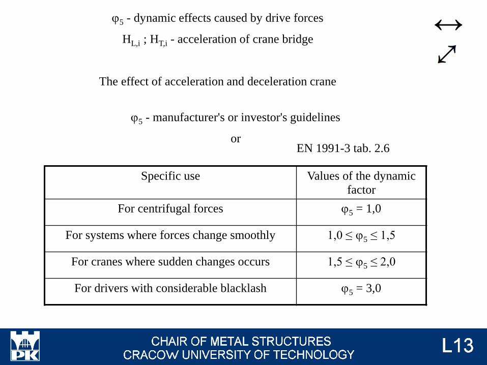
j5 - manufacturer's or investor's guidelines
or
j5 - dynamic effects caused by drive forces
HL,i ; HT,i - acceleration of crane bridge
The effect of acceleration and deceleration crane
EN 1991-3 tab. 2.6
↔
Specific use Values of the dynamic
factor
For centrifugal forces j5 = 1,0
For systems where forces change smoothly 1,0 ≤ j5 ≤ 1,5
For cranes where sudden changes occurs 1,5 ≤ j5 ≤ 2,0
For drivers with considerable blacklash j5 = 3,0
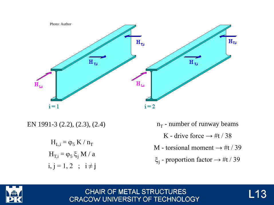
HL,i = j5 K / nT
HT,i = j5 xj M / a
i, j = 1, 2 ; i ≠ j
EN 1991-3 (2.2), (2.3), (2.4) nT - number of runway beams
K - drive force → #t / 38
M - torsional moment → #t / 39
xj - proportion factor → #t / 39
Photo: Author
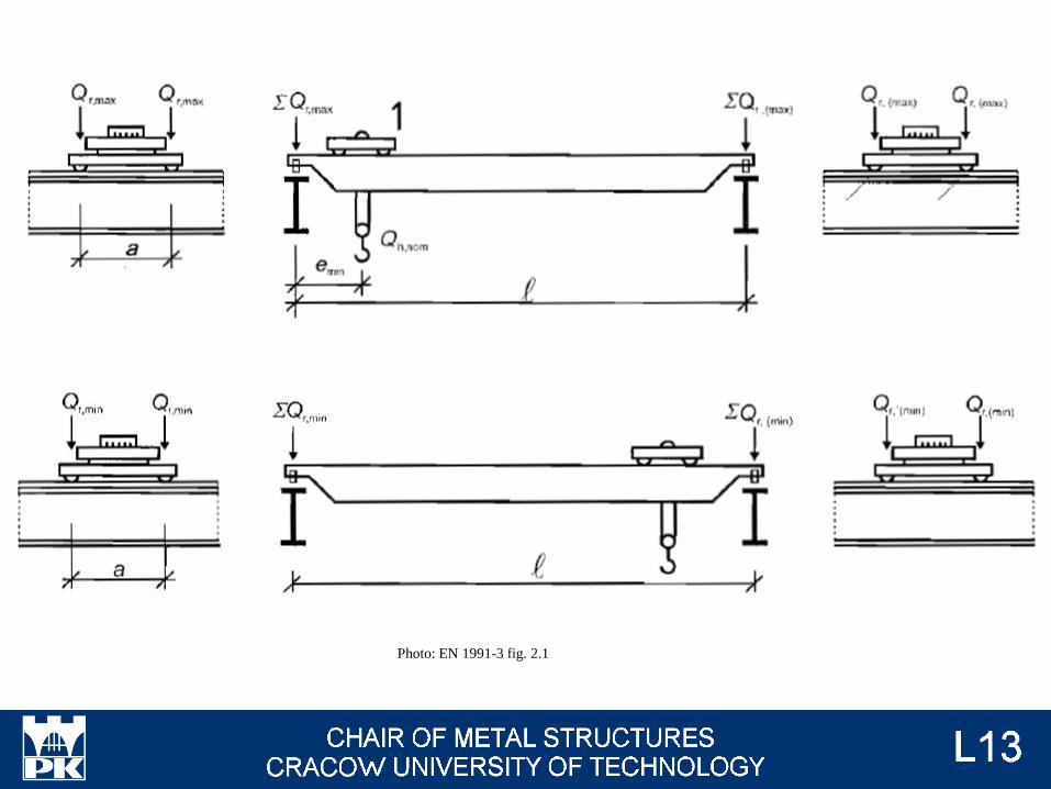
Photo: EN 1991-3 fig. 2.1
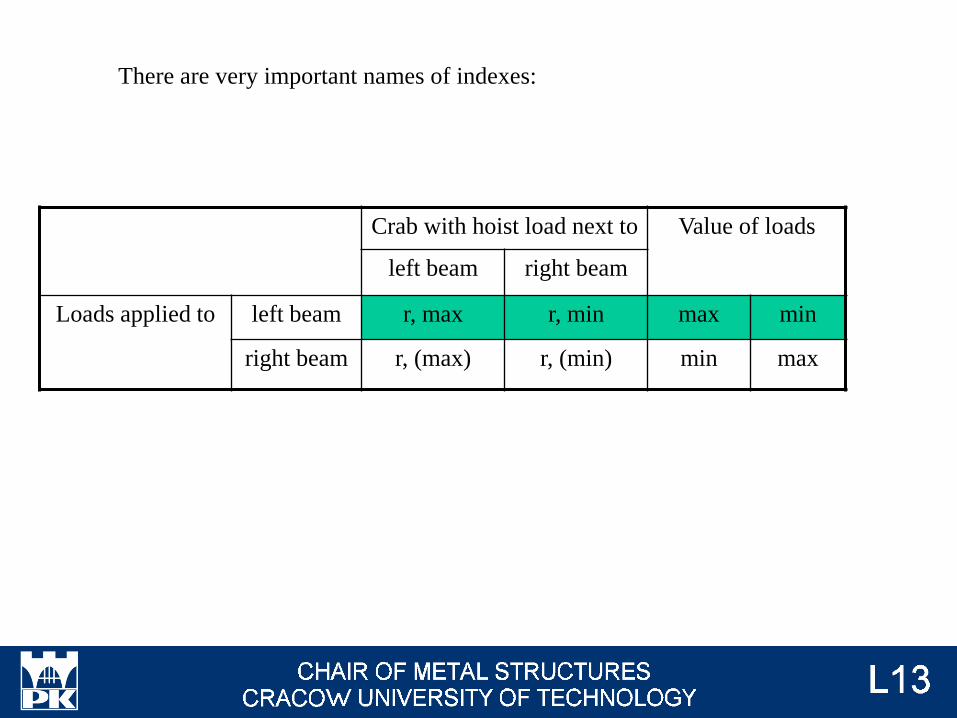
There are very important names of indexes:
Crab with hoist load next to Value of loads
left beam right beam
Loads applied to left beam r, max r, min max min
right beam r, (max) r, (min) min max
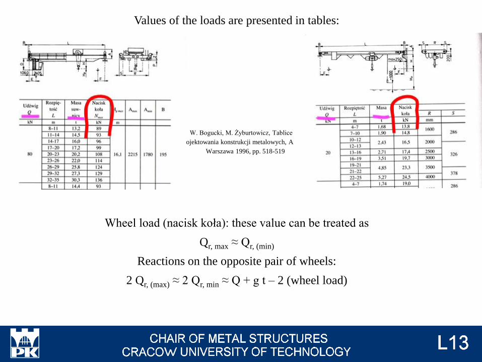
Values of the loads are presented in tables:
W. Bogucki, M. Żyburtowicz, Tablice do
projektowania konstrukcji metalowych, Arkady,
Warszawa 1996, pp. 518-519
Wheel load (nacisk koła): these value can be treated as
Qr, max ≈ Qr, (min)
Reactions on the opposite pair of wheels:
2 Qr, (max) ≈ 2 Qr, min ≈ Q + g t – 2 (wheel load)
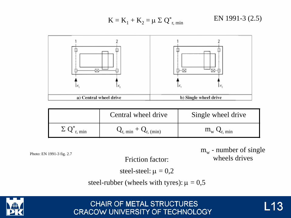
K = K1 + K2 = m S Q*r, min
Central wheel drive Single wheel drive
S Q*r, min Qr, min + Qr, (min) mw Qr, min
Photo: EN 1991-3 fig. 2.7
EN 1991-3 (2.5)
mw - number of single
wheels drivesFriction factor:
steel-steel: m = 0,2
steel-rubber (wheels with tyres): m = 0,5
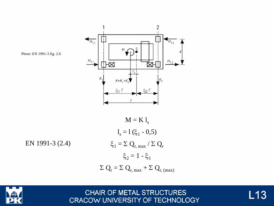
M = K ls
ls = l (x1 - 0,5)
x1 = S Qr, max / S Qr
x2 = 1 - x1
S Qr = S Qr, max + S Qr, (max)
Photo: EN 1991-3 fig. 2.6
EN 1991-3 (2.4)
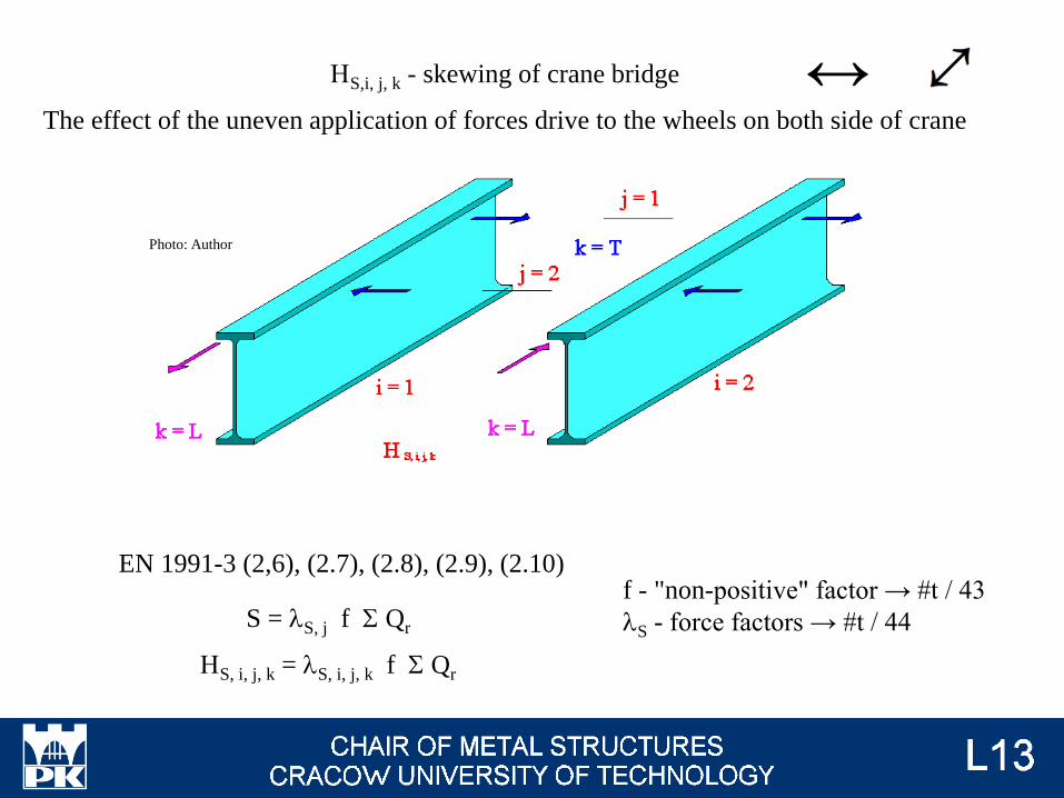
S = lS, j f S Qr
HS, i, j, k = lS, i, j, k f S Qr
HS,i, j, k - skewing of crane bridge
The effect of the uneven application of forces drive to the wheels on both side of crane
EN 1991-3 (2,6), (2.7), (2.8), (2.9), (2.10)f - "non-positive" factor → #t / 43
lS - force factors → #t / 44
↔
Photo: Author
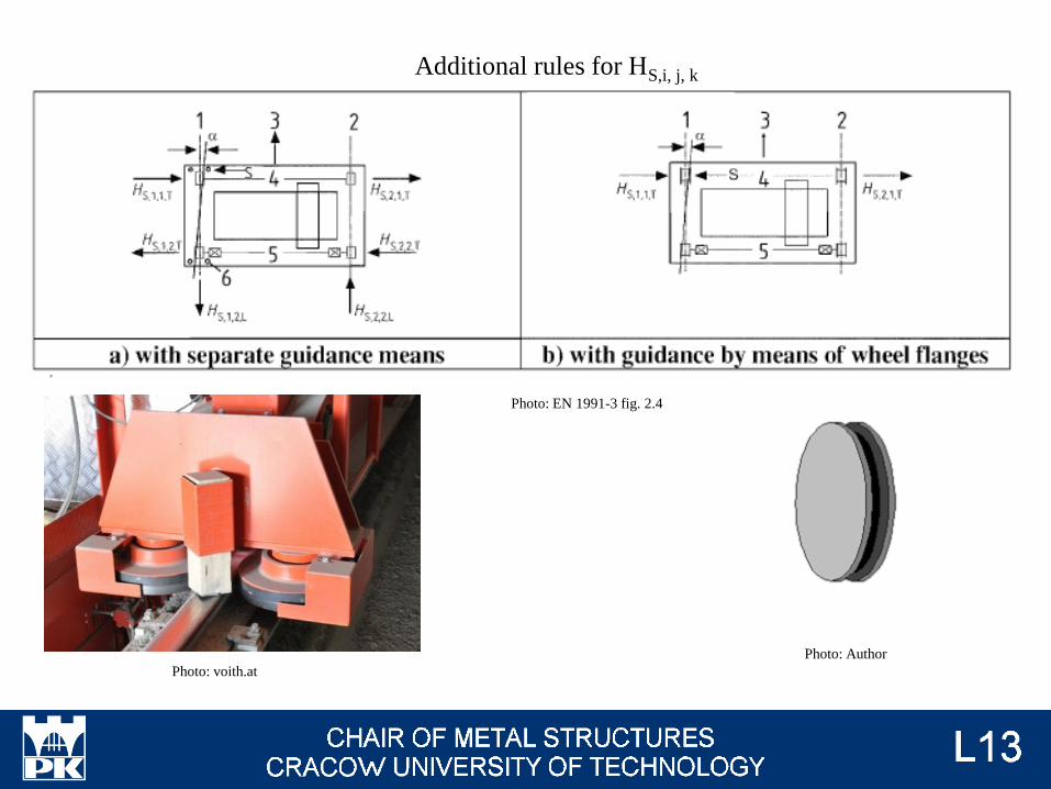
Photo: EN 1991-3 fig. 2.4
Additional rules for HS,i, j, k
Photo: Author
Photo: voith.at
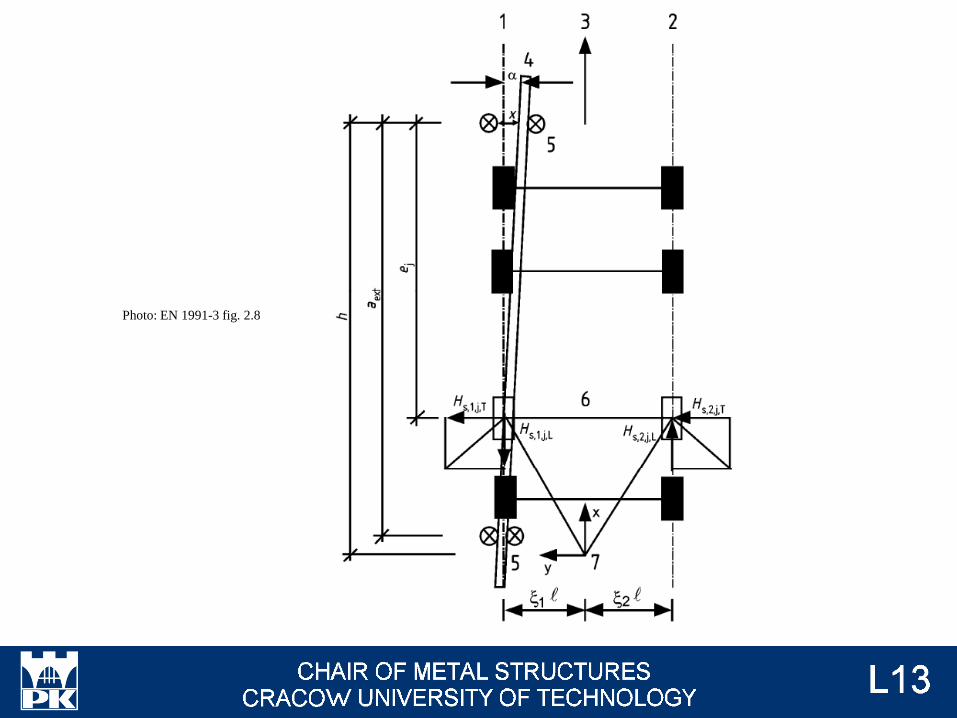
Photo: EN 1991-3 fig. 2.8
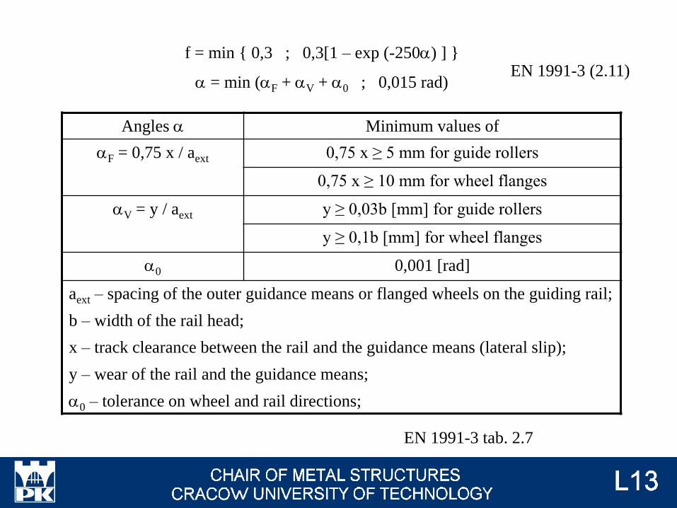
f = min { 0,3 ; 0,3[1 – exp (-250a) ] }
a = min (aF + aV + a0 ; 0,015 rad)
EN 1991-3 tab. 2.7
EN 1991-3 (2.11)
Angles a Minimum values of
aF = 0,75 x / aext 0,75 x ≥ 5 mm for guide rollers
0,75 x ≥ 10 mm for wheel flanges
aV = y / aext y ≥ 0,03b [mm] for guide rollers
y ≥ 0,1b [mm] for wheel flanges
a0 0,001 [rad]
aext – spacing of the outer guidance means or flanged wheels on the guiding rail;
b – width of the rail head;
x – track clearance between the rail and the guidance means (lateral slip);
y – wear of the rail and the guidance means;
a0 – tolerance on wheel and rail directions;
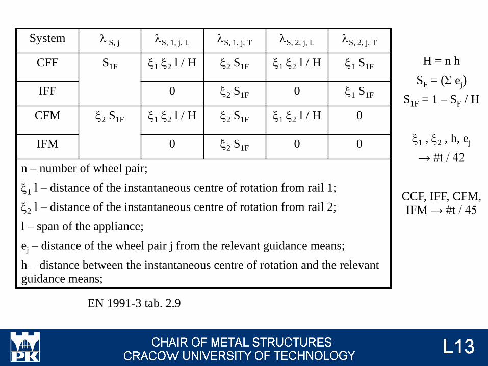
EN 1991-3 tab. 2.9
H = n h
SF = (S ej)
S1F = 1 – SF / H
x1 , x2 , h, ej
→ #t / 42
CCF, IFF, CFM,
IFM → #t / 45
System l S, j lS, 1, j, L lS, 1, j, T lS, 2, j, L lS, 2, j, T
CFF S1F x1 x2 l / H x2 S1F x1 x2 l / H x1 S1F
IFF 0 x2 S1F 0 x1 S1F
CFM x2 S1F x1 x2 l / H x2 S1F x1 x2 l / H 0
IFM 0 x2 S1F 0 0
n – number of wheel pair;
x1 l – distance of the instantaneous centre of rotation from rail 1;
x2 l – distance of the instantaneous centre of rotation from rail 2;
l – span of the appliance;
ej – distance of the wheel pair j from the relevant guidance means;
h – distance between the instantaneous centre of rotation and the relevant
guidance means;
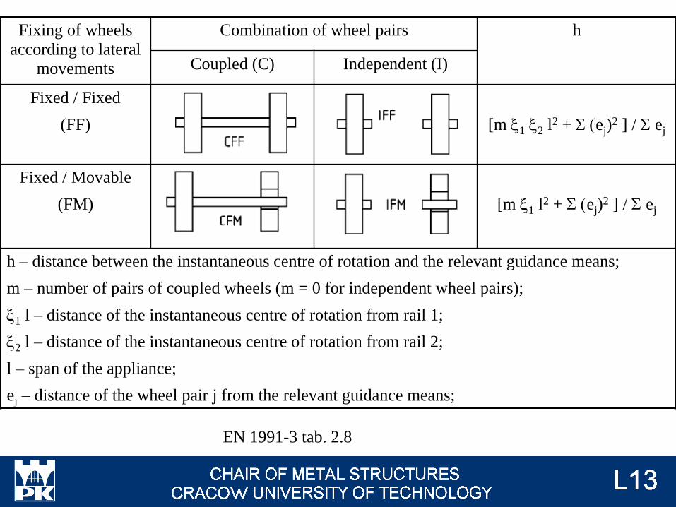
EN 1991-3 tab. 2.8
Fixing of wheels
according to lateral
movements
Combination of wheel pairs h
Coupled (C) Independent (I)
Fixed / Fixed
(FF) [m x1 x2 l2 + S (ej)2 ] / S ej
Fixed / Movable
(FM) [m x1 l2 + S (ej)2 ] / S ej
h – distance between the instantaneous centre of rotation and the relevant guidance means;
m – number of pairs of coupled wheels (m = 0 for independent wheel pairs);
x1 l – distance of the instantaneous centre of rotation from rail 1;
x2 l – distance of the instantaneous centre of rotation from rail 2;
l – span of the appliance;
ej – distance of the wheel pair j from the relevant guidance means;
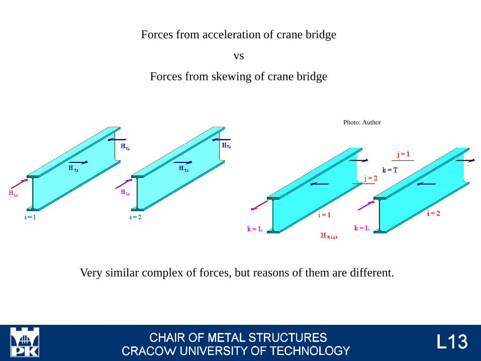
Forces from acceleration of crane bridge
vs
Forces from skewing of crane bridge
Photo: Author
Very similar complex of forces, but reasons of them are different.
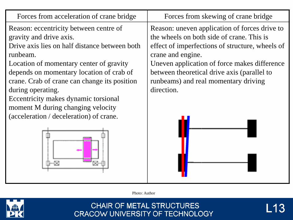
Forces from acceleration of crane bridge Forces from skewing of crane bridge
Reason: eccentricity between centre of
gravity and drive axis.
Drive axis lies on half distance between both
runbeam.
Location of momentary center of gravity
depends on momentary location of crab of
crane. Crab of crane can change its position
during operating.
Eccentricity makes dynamic torsional
moment M during changing velocity
(acceleration / deceleration) of crane.
Reason: uneven application of forces drive to
the wheels on both side of crane. This is
effect of imperfections of structure, wheels of
crane and engine.
Uneven application of force makes difference
between theoretical drive axis (parallel to
runbeams) and real momentary driving
direction.
Photo: Author
HT3 - acceleration or braking of crab or hoist block
EN 1991-3 2.7.5
↔
Acceleration or braking of crab or hoist block can be covered by horizontal force HB,2
(buffer forces related to movements of crab), given in EN 1991-3 2.11.2 → #t / 49
EN 1991-3 2.11.2
Buffer forces related to movements of crab HB,2 ↔
• Buffer forces related to movements of crab can be assumed as:
0,1 (self-weight of crab + hoist load);
• In other case, this force should be determined as for the crane movement → #t / 59;
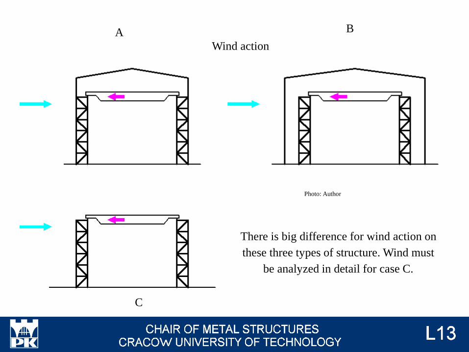
A B
C
There is big difference for wind action on
these three types of structure. Wind must
be analyzed in detail for case C.
Wind action
Photo: Author
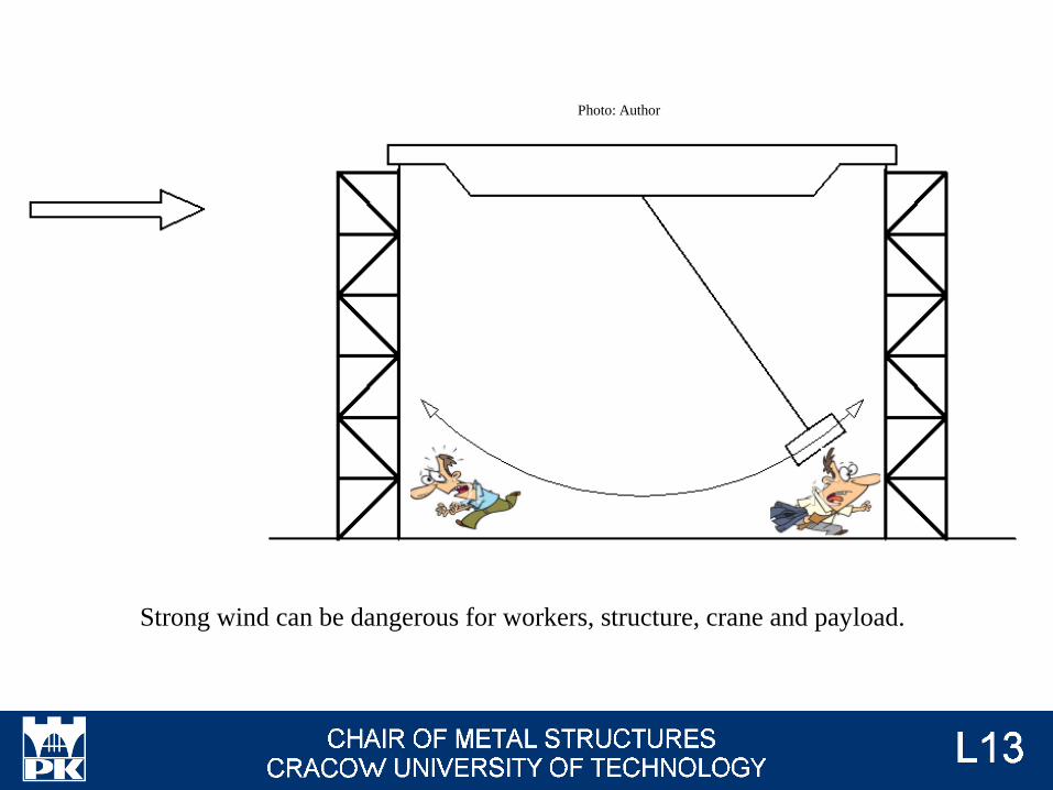
Strong wind can be dangerous for workers, structure, crane and payload.
Photo: Author
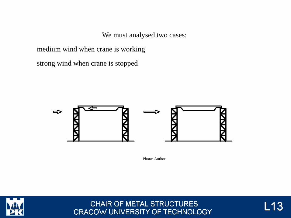
We must analysed two cases:
medium wind when crane is working
strong wind when crane is stopped
Photo: Author
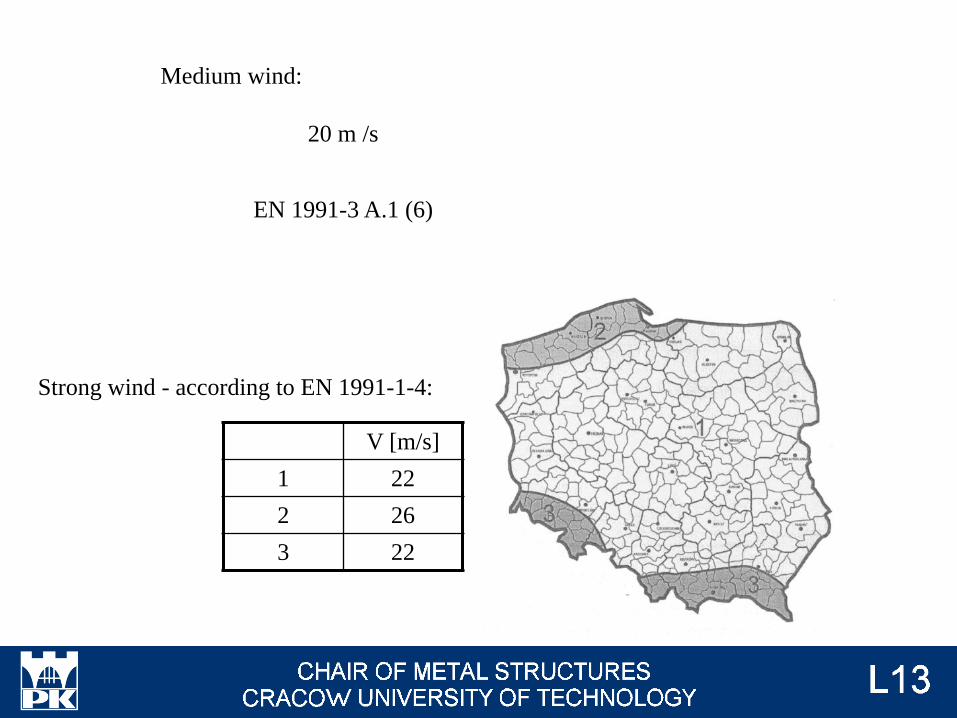
V [m/s]
1 22
2 26
3 22
20 m /s
EN 1991-3 A.1 (6)
Strong wind - according to EN 1991-1-4:
Medium wind:
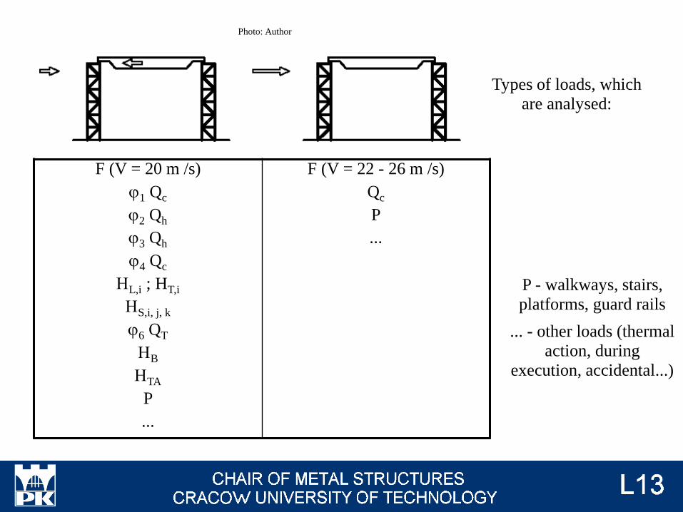
F (V = 20 m /s)
j1 Qc
j2 Qh
j3 Qh
j4 Qc
HL,i ; HT,i
HS,i, j, k
j6 QT
HB
HTA
P
...
F (V = 22 - 26 m /s)
Qc
P
...
Types of loads, which
are analysed:
P - walkways, stairs,
platforms, guard rails
... - other loads (thermal
action, during
execution, accidental...)
Photo: Author
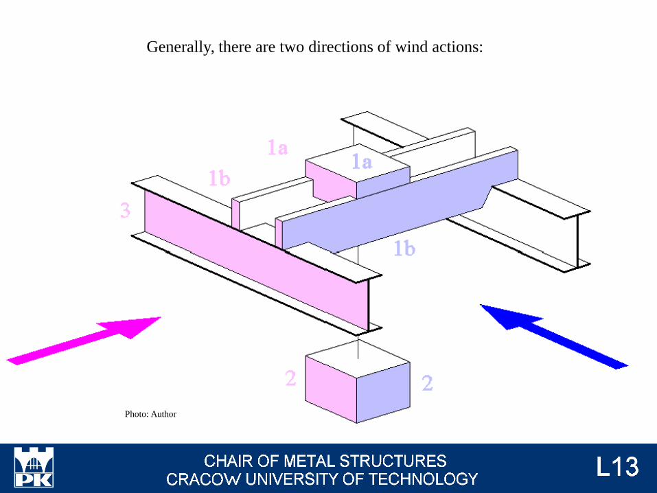
Generally, there are two directions of wind actions:
Photo: Author
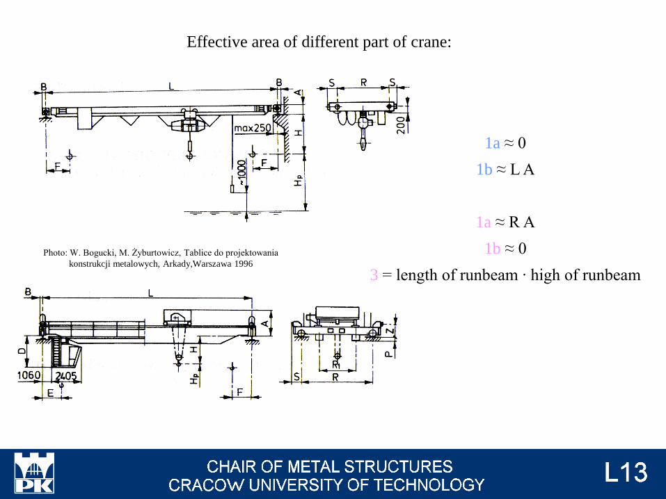
Effective area of different part of crane:
1a ≈ 0
1b ≈ L A
1a ≈ R A
1b ≈ 0
3 = length of runbeam ∙ high of runbeam
Photo: W. Bogucki, M. Żyburtowicz, Tablice do projektowania
konstrukcji metalowych, Arkady,Warszawa 1996

Aref,x - manufacturer's or investor's guidelines
or
PN-M 06514
Aref,x [m2] = Qh [t] Qh ≤ 12,5 t
Aref,x [m2] = 3,5 √Qh [t] Qh > 12,5 t
Area of payload (2):
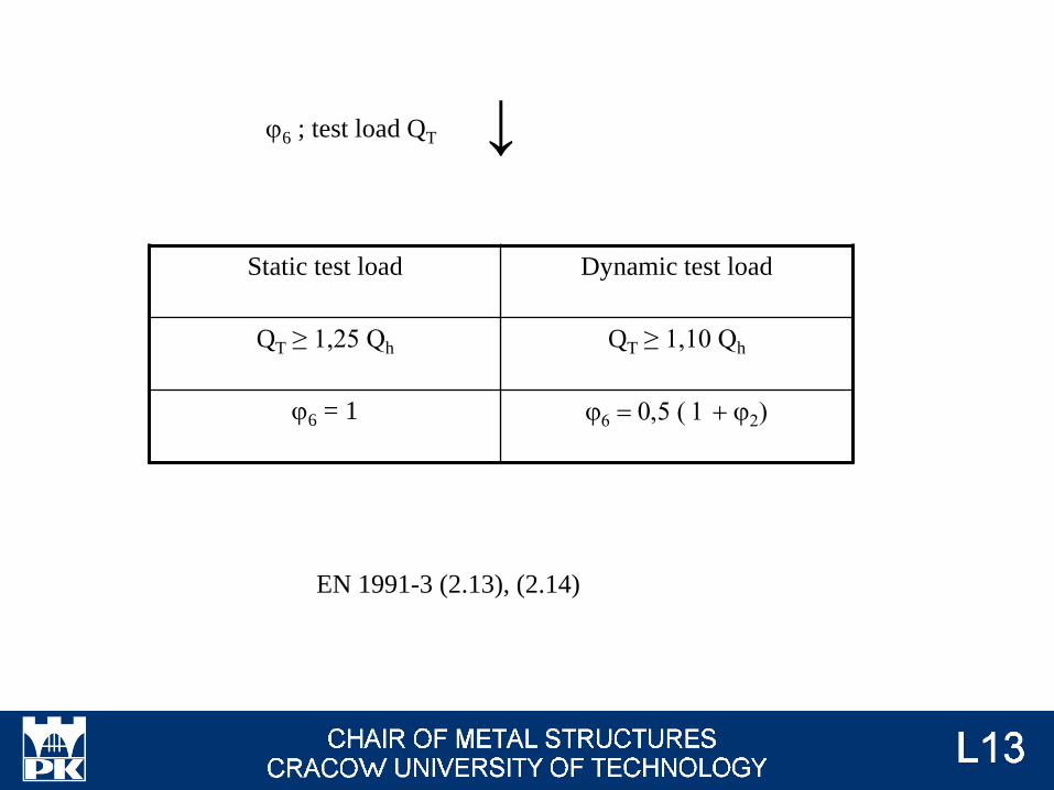
Static test load Dynamic test load
QT ≥ 1,25 Qh QT ≥ 1,10 Qh
j6 = 1 j6 = 0,5 ( 1 + j2)
j6 ; test load QT
EN 1991-3 (2.13), (2.14)
↓
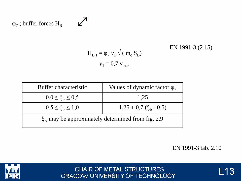
HB,1 = j7 v1 √ ( mc SB)
v1 = 0,7 vmax
j7 ; buffer forces HB
EN 1991-3 (2.15)
EN 1991-3 tab. 2.10
↔
Buffer characteristic Values of dynamic factor j7
0,0 ≤ xb ≤ 0,5 1,25
0,5 ≤ xb ≤ 1,0 1,25 + 0,7 (xb - 0,5)
xb may be approximately determined from fig. 2.9
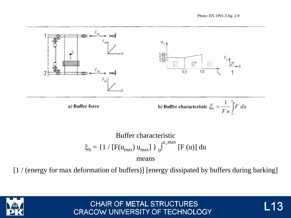
Photo: EN 1991-3 fig. 2.9
Buffer characteristic
xb = {1 / [F(umax) umax] } 0∫u_max
[F (u)] du
means
[1 / (energy for max deformation of buffers)] [energy dissipated by buffers during barking]
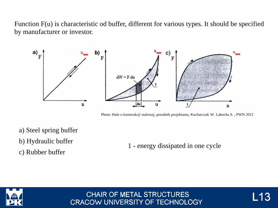
Function F(u) is characteristic od buffer, different for various types. It should be specified
by manufacturer or investor.
a) Steel spring buffer
b) Hydraulic buffer
c) Rubber buffer
Photo: Hale o konstrukcji stalowej, poradnik projektanta, Kucharczuk W. Labocha S. , PWN 2012
1 - energy dissipated in one cycle
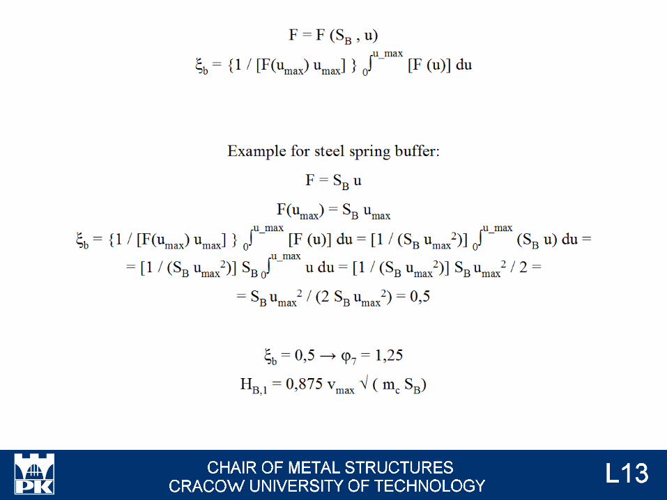
F = F (SB , u)
xb = {1 / [F(umax) umax] } 0∫u_max
[F (u)] du
Example for steel spring buffer:
F = SB u
F(umax) = SB umax
xb = {1 / [F(umax) umax] } 0∫u_max
[F (u)] du = [1 / (SB umax2)]
0∫u_max
(SB u) du =
= [1 / (SB umax2)] SB 0
∫u_max
u du = [1 / (SB umax2)] SB umax
2 / 2 =
= SB umax2 / (2 SB umax
2) = 0,5
xb = 0,5 → j7 = 1,25
HB,1 = 0,875 vmax √ ( mc SB)
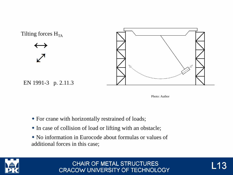
Tilting forces HTA
EN 1991-3 p. 2.11.3
↔
Photo: Author
For crane with horizontally restrained of loads;
In case of collision of load or lifting with an obstacle;
No information in Eurocode about formulas or values of
additional forces in this case;

Photo: manulift.com.pl
Photo: manulift.com.pl
Tilting forces should be analysed first of all in
case of rigid lifting.
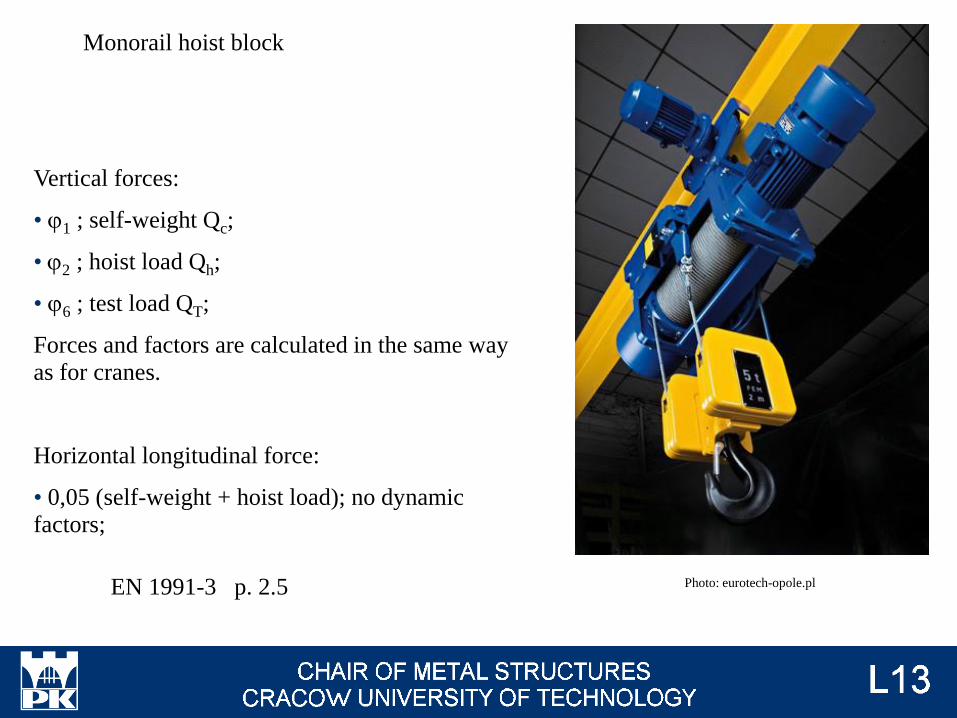
Monorail hoist block
EN 1991-3 p. 2.5 Photo: eurotech-opole.pl
Vertical forces:
• j1 ; self-weight Qc;
• j2 ; hoist load Qh;
• j6 ; test load QT;
Forces and factors are calculated in the same way
as for cranes.
Horizontal longitudinal force:
• 0,05 (self-weight + hoist load); no dynamic
factors;
EN 1991-3 p. 2.9
Photo: megatem-ec.pl
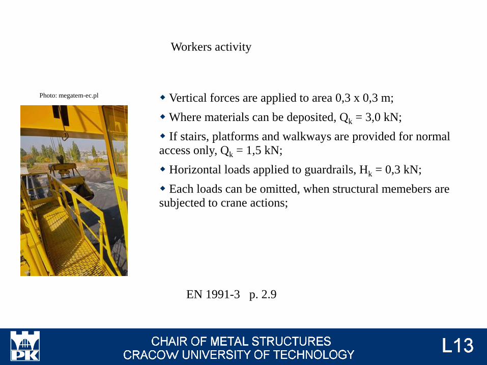
Workers activity
Vertical forces are applied to area 0,3 x 0,3 m;
Where materials can be deposited, Qk = 3,0 kN;
If stairs, platforms and walkways are provided for normal
access only, Qk = 1,5 kN;
Horizontal loads applied to guardrails, Hk = 0,3 kN;
Each loads can be omitted, when structural memebers are
subjected to crane actions;

gFf DsE / (sR / gMf) ≤ 1,0
gFf DtE / (tR / gMf) ≤ 1,0
Checking of fatugue resistance will be presented on lecture #5, at now only
calculation of load is presented.
Fatigue loads
EN 1991-1-9 (8.2)
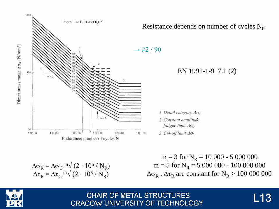
DsR = DsCm√ (2 ∙ 106 / NR)
DtR = DtCm√ (2 ∙ 106 / NR)
Resistance depends on number of cycles NR
m = 3 for NR = 10 000 - 5 000 000
m = 5 for NR = 5 000 000 - 100 000 000
DsR , DtR are constant for NR > 100 000 000
EN 1991-1-9 7.1 (2)
Photo: EN 1991-1-9 fig.7.1
→ #2 / 90
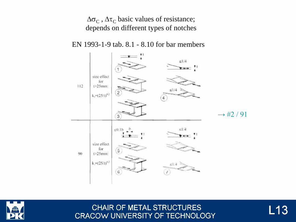
EN 1993-1-9 tab. 8.1 - 8.10 for bar members
DsC , DtC basic values of resistance;
depends on different types of notches
→ #2 / 91
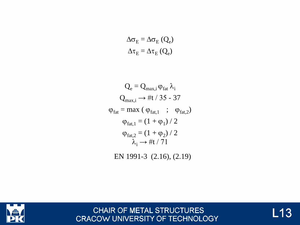
DsE = DsE (Qe)
DtE = DtE (Qe)
Qe = Qmax,i jfat li
Qmax,i → #t / 35 - 37
jfat = max ( jfat,1 ; jfat,2)
jfat,1 = (1 + j1) / 2
jfat,2 = (1 + j2) / 2
li → #t / 71
EN 1991-3 (2.16), (2.19)
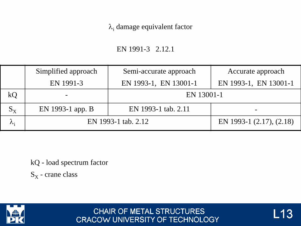
li damage equivalent factor
Simplified approach
EN 1991-3
Semi-accurate approach
EN 1993-1, EN 13001-1
Accurate approach
EN 1993-1, EN 13001-1
kQ - EN 13001-1
SX EN 1993-1 app. B EN 1993-1 tab. 2.11 -
li EN 1993-1 tab. 2.12 EN 1993-1 (2.17), (2.18)
EN 1991-3 2.12.1
kQ - load spectrum factor
SX - crane class
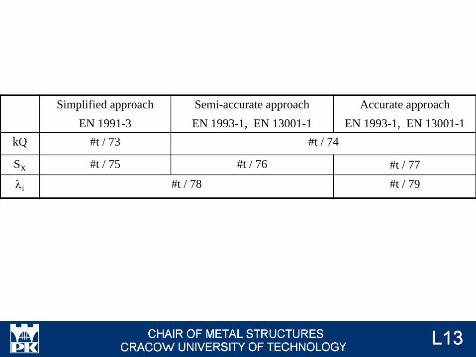
Simplified approach
EN 1991-3
Semi-accurate approach
EN 1993-1, EN 13001-1
Accurate approach
EN 1993-1, EN 13001-1
kQ #t / 73 #t / 74
SX #t / 75 #t / 76 #t / 77
li #t / 78 #t / 79

Not exists
kQ, load spectrum factor - simplified approach
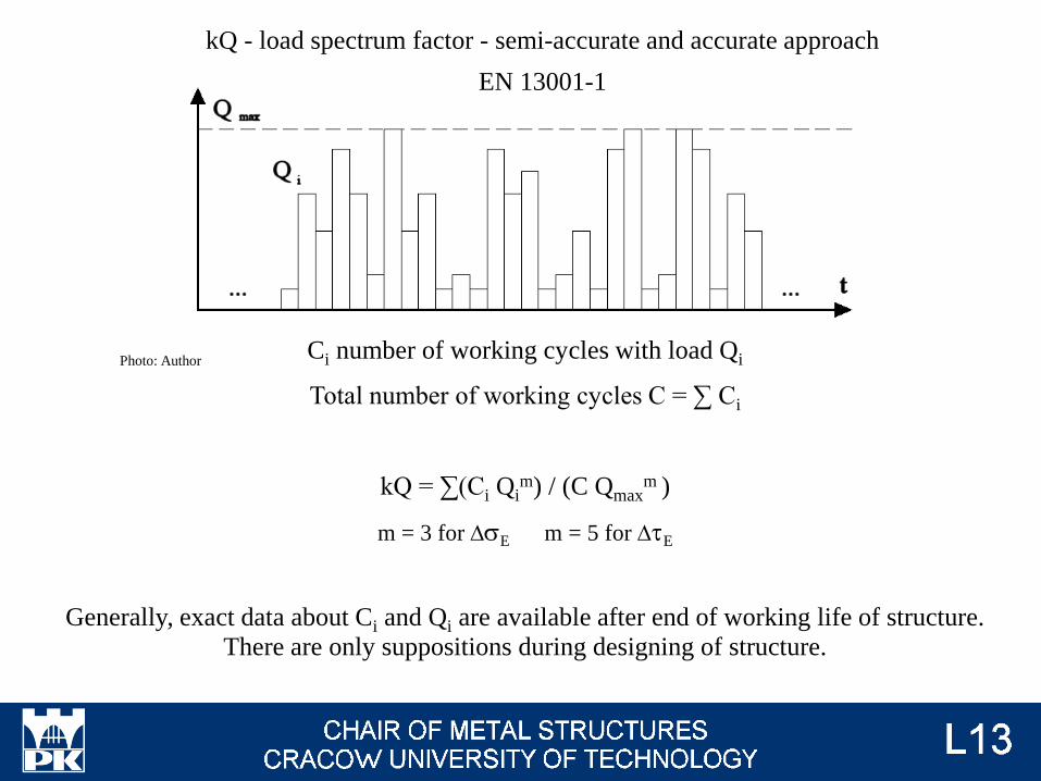
Ci number of working cycles with load Qi
Total number of working cycles C = ∑ Ci
kQ = ∑(Ci Qim) / (C Qmax
m )
m = 3 for DsE m = 5 for DtE
Generally, exact data about Ci and Qi are available after end of working life of structure.
There are only suppositions during designing of structure.
kQ - load spectrum factor - semi-accurate and accurate approach
EN 13001-1
Photo: Author
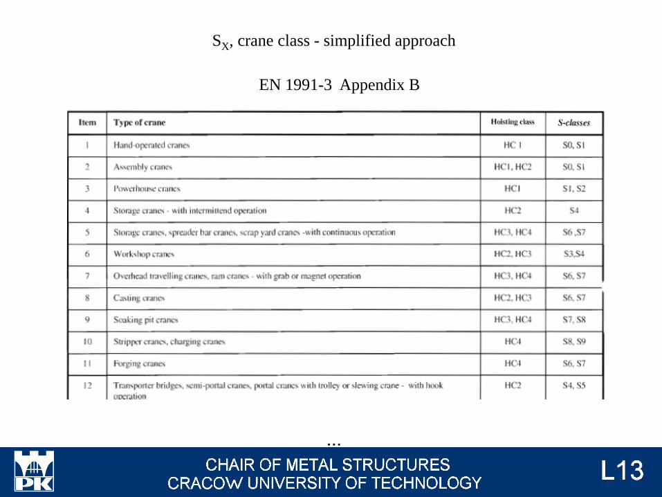
EN 1991-3 Appendix B
...
SX, crane class - simplified approach
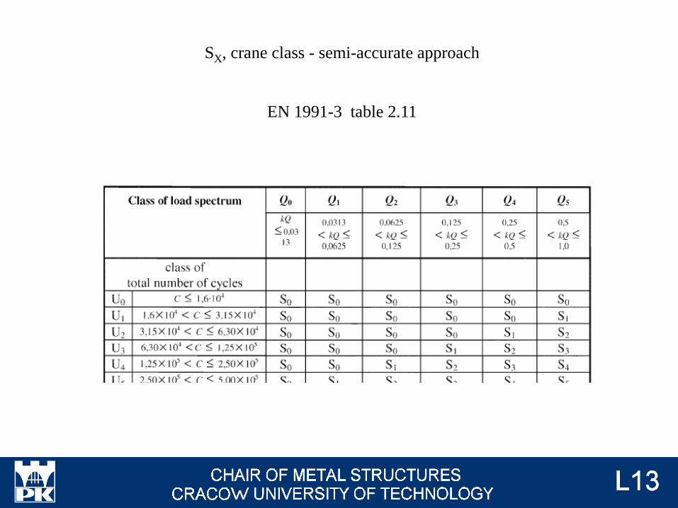
SX, crane class - semi-accurate approach
EN 1991-3 table 2.11

Not exists
SX, crane class - accurate approach
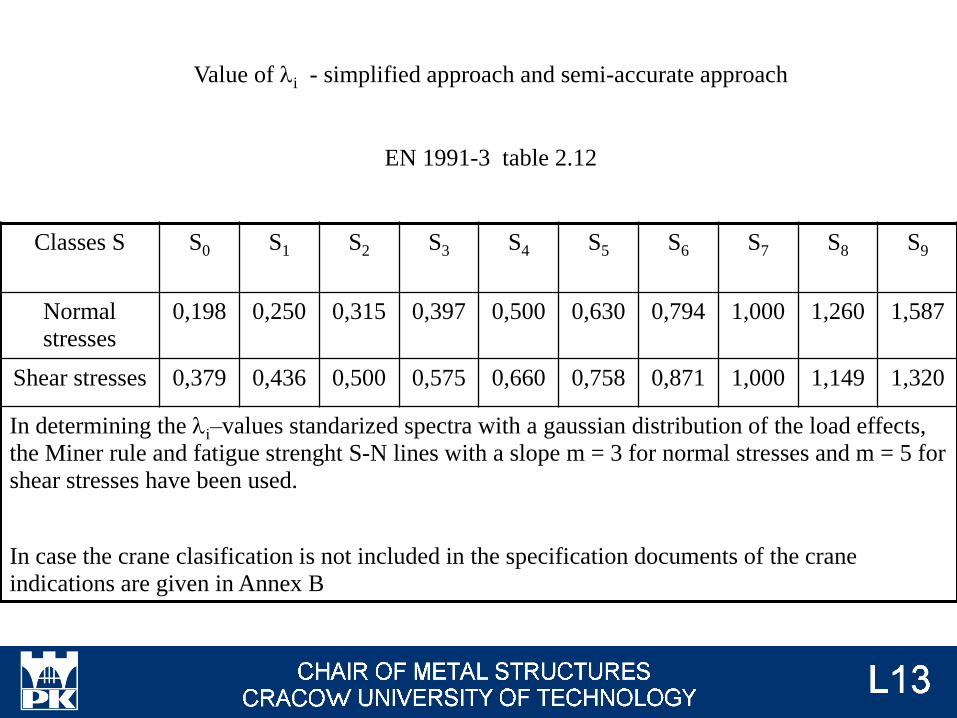
Value of li - simplified approach and semi-accurate approach
EN 1991-3 table 2.12
Classes S S0 S1 S2 S3 S4 S5 S6 S7 S8 S9
Normal
stresses
0,198 0,250 0,315 0,397 0,500 0,630 0,794 1,000 1,260 1,587
Shear stresses 0,379 0,436 0,500 0,575 0,660 0,758 0,871 1,000 1,149 1,320
In determining the li–values standarized spectra with a gaussian distribution of the load effects,
the Miner rule and fatigue strenght S-N lines with a slope m = 3 for normal stresses and m = 5 for
shear stresses have been used.
In case the crane clasification is not included in the specification documents of the crane
indications are given in Annex B

li = m√(kQ C / N)
kQ → #t / 74
C → #t / 74
N = 2 ∙ 106
m = 3 for DsE
m = 5 for DtE
EN 1991-3 (2.17), (2.18)
Value of li - accurate approach
Serviceability Limit States
g = 1,0
Acceptable values of deflections and deformations of crane supporting structures
will be presented on lecture #5.
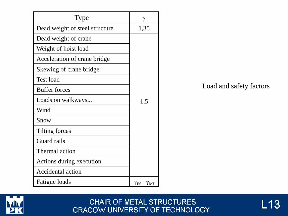
Load and safety factors
Type g
Dead weight of steel structure 1,35
Dead weight of crane
1,5
Weight of hoist load
Acceleration of crane bridge
Skewing of crane bridge
Test load
Buffer forces
Loads on walkways...
Wind
Snow
Tilting forces
Guard rails
Thermal action
Actions during execution
Accidental action
Fatigue loads gFf gMf

Combinations of loads
How many cranes we should take into consideration? → #t / 83
For which position of cranes on runbeam we have max values of cross-sectional
forces? → #t / 84 - 88
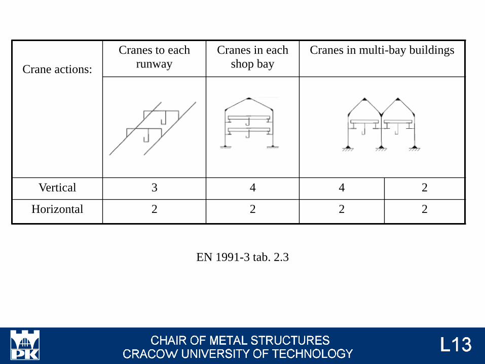
EN 1991-3 tab. 2.3
Crane actions:
Cranes to each
runway
Cranes in each
shop bay
Cranes in multi-bay buildings
Vertical 3 4 4 2
Horizontal 2 2 2 2
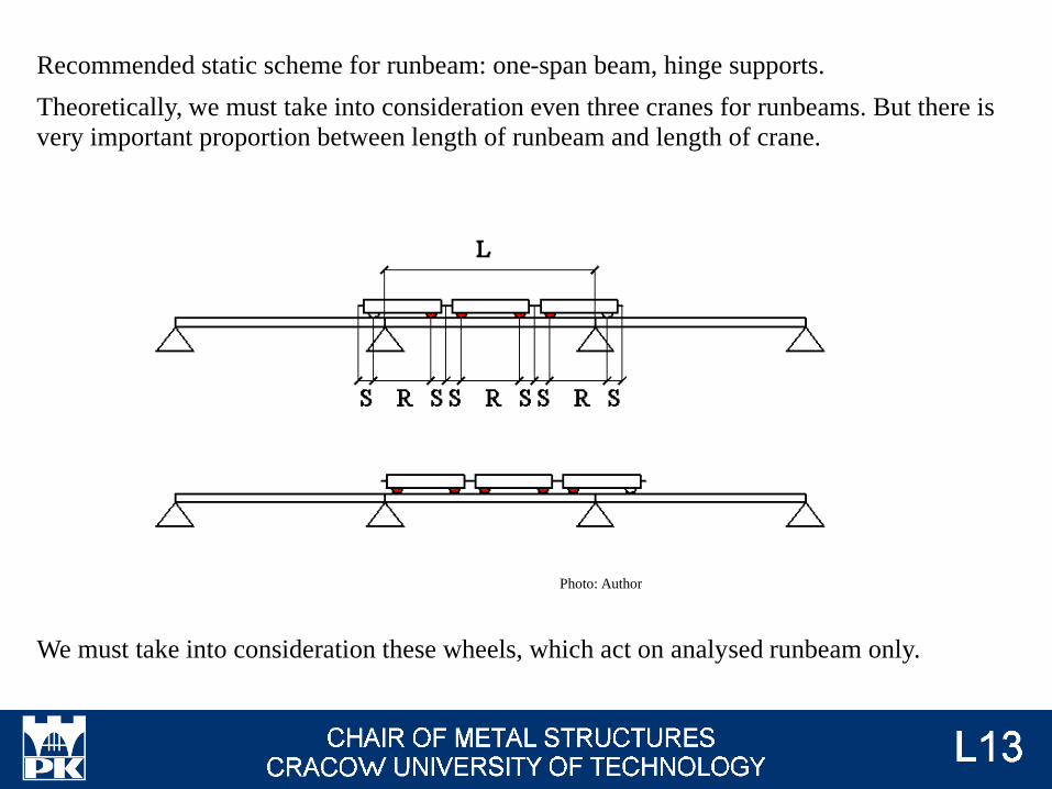
Recommended static scheme for runbeam: one-span beam, hinge supports.
Theoretically, we must take into consideration even three cranes for runbeams. But there is
very important proportion between length of runbeam and length of crane.
We must take into consideration these wheels, which act on analysed runbeam only.
Photo: Author
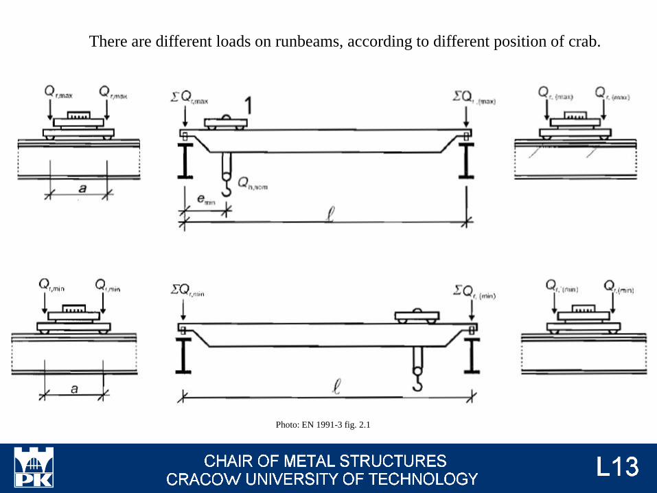
Photo: EN 1991-3 fig. 2.1
There are different loads on runbeams, according to different position of crab.
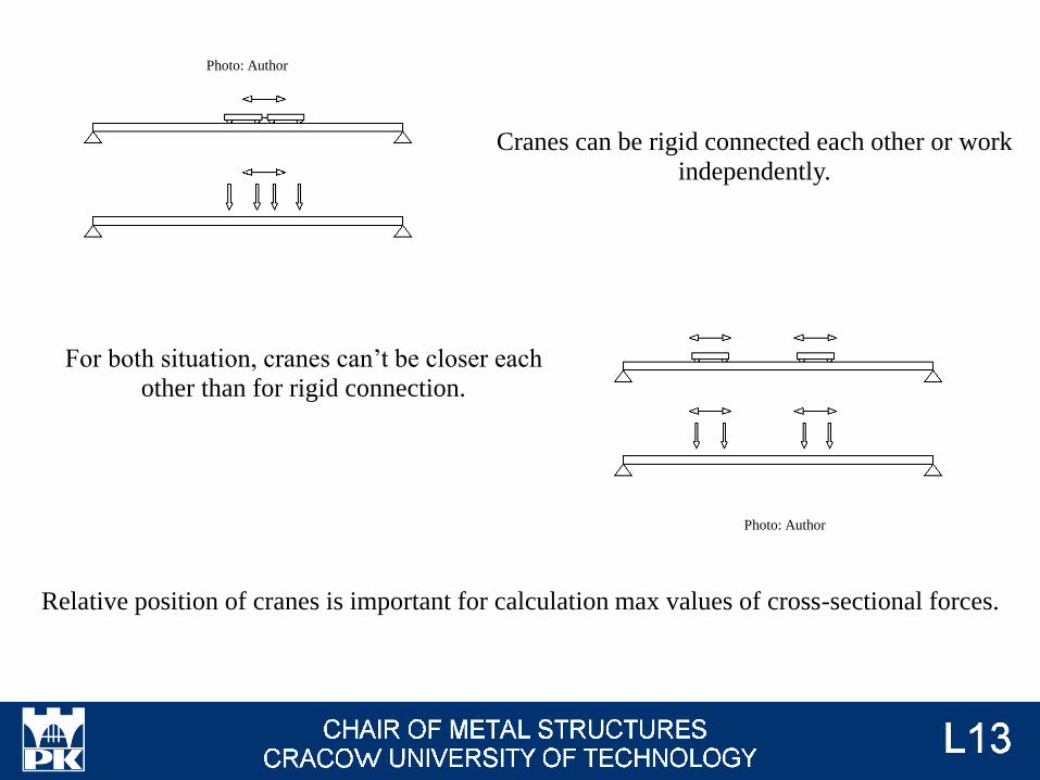
Cranes can be rigid connected each other or work
independently.
For both situation, cranes can’t be closer each
other than for rigid connection.
Relative position of cranes is important for calculation max values of cross-sectional forces.
Photo: Author
Photo: Author
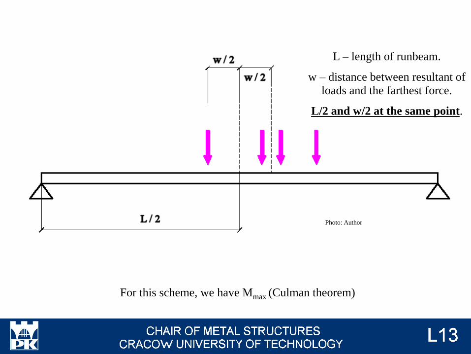
For this scheme, we have Mmax (Culman theorem)
L – length of runbeam.
w – distance between resultant of
loads and the farthest force.
L/2 and w/2 at the same point.
Photo: Author
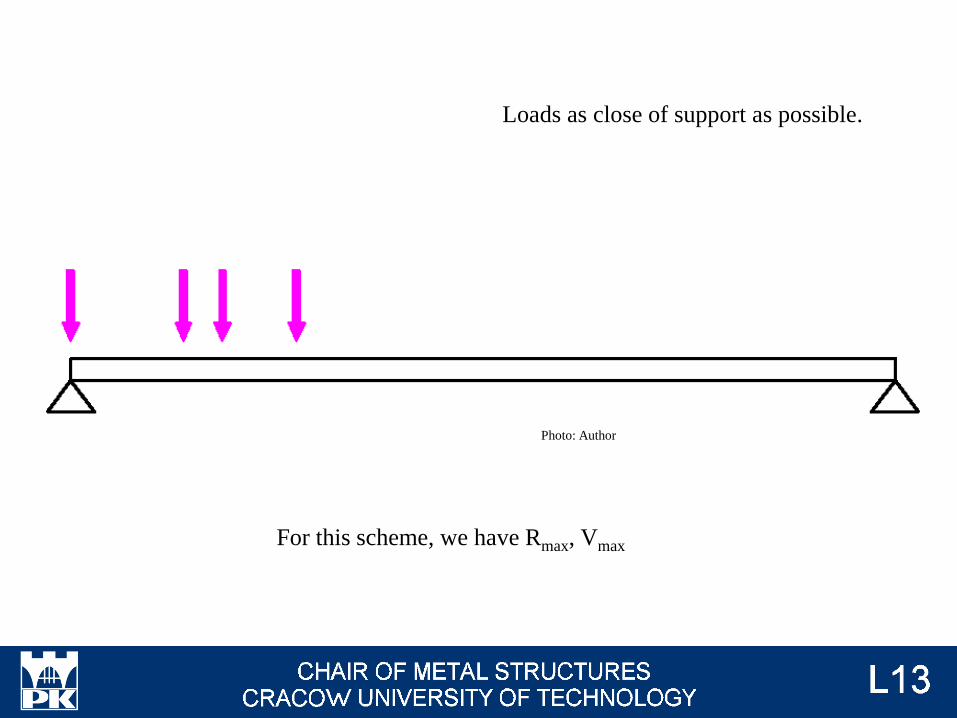
For this scheme, we have Rmax, Vmax
Loads as close of support as possible.
Photo: Author
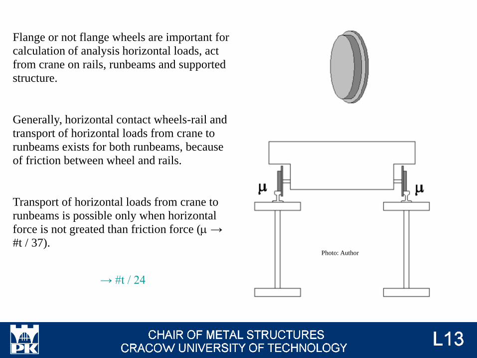
Flange or not flange wheels are important for
calculation of analysis horizontal loads, act
from crane on rails, runbeams and supported
structure.
Generally, horizontal contact wheels-rail and
transport of horizontal loads from crane to
runbeams exists for both runbeams, because
of friction between wheel and rails.
Transport of horizontal loads from crane to
runbeams is possible only when horizontal
force is not greated than friction force (m →
#t / 37).Photo: Author
→ #t / 24
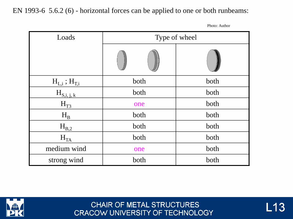
EN 1993-6 5.6.2 (6) - horizontal forces can be applied to one or both runbeams:
Loads Type of wheel
HL,i ; HT,i both both
HS,i, j, k both both
HT3 one both
HB both both
HB,2 both both
HTA both both
medium wind one both
strong wind both both
Photo: Author
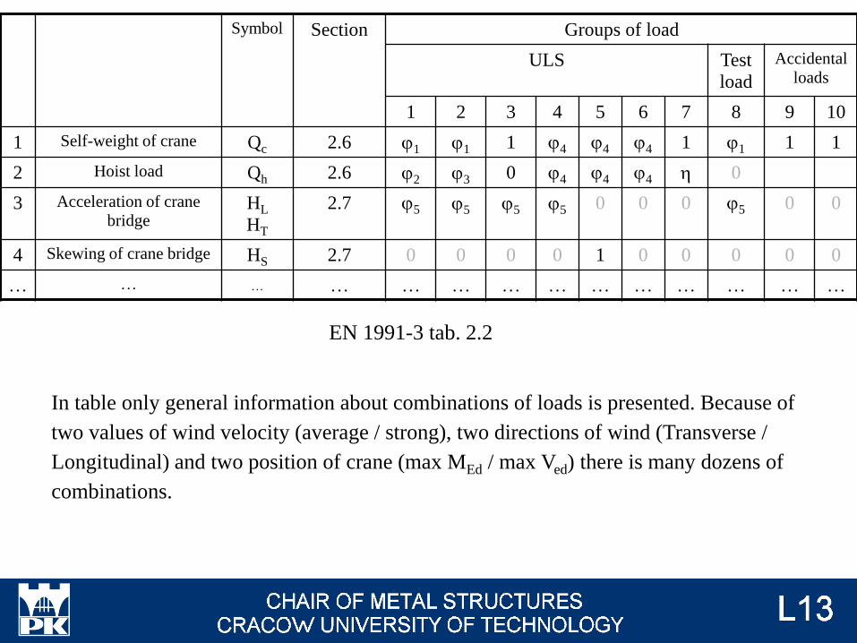
Symbol Section Groups of load
ULS Test
load
Accidental
loads
1 2 3 4 5 6 7 8 9 10
1 Self-weight of crane Qc 2.6 j1 j1 1 j4 j4 j4 1 j1 1 1
2 Hoist load Qh 2.6 j2 j3 0 j4 j4 j4 h 0
3 Acceleration of crane
bridgeHL
HT
2.7 j5 j5 j5 j5 0 0 0 j5 0 0
4 Skewing of crane bridge HS 2.7 0 0 0 0 1 0 0 0 0 0
… … … … … … … … … … … … … …
EN 1991-3 tab. 2.2
In table only general information about combinations of loads is presented. Because of
two values of wind velocity (average / strong), two directions of wind (Transverse /
Longitudinal) and two position of crane (max MEd / max Ved) there is many dozens of
combinations.
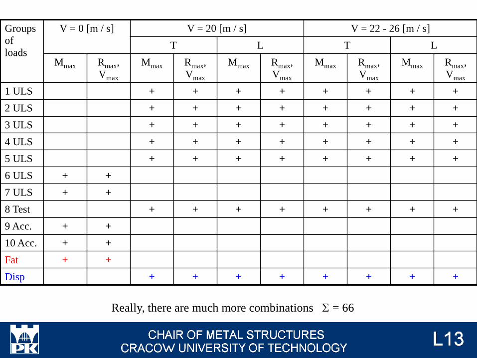
Groups
of
loads
V = 0 [m / s] V = 20 [m / s] V = 22 - 26 [m / s]
T L T L
Mmax Rmax,
Vmax
Mmax Rmax,
Vmax
Mmax Rmax,
Vmax
Mmax Rmax,
Vmax
Mmax Rmax,
Vmax
1 ULS + + + + + + + +
2 ULS + + + + + + + +
3 ULS + + + + + + + +
4 ULS + + + + + + + +
5 ULS + + + + + + + +
6 ULS + +
7 ULS + +
8 Test + + + + + + + +
9 Acc. + +
10 Acc. + +
Fat + +
Disp + + + + + + + +
Really, there are much more combinations S = 66

Dynamic factors, enumeration and explanation
Loads, enumeration and explanation
Wind action on crane supporting structures
Way of calculations of fatigue actions
Examination issues

Hoist block - wciągnikOverhead travelling crane - suwnica pomostowaUnderslung crane - suwnica podwieszonaTop-mounted crane - suwnica natorowaCrab - wózek suwnicyCrane bridge - pomost suwnicyGuidance means - elementy prowadząceGantry crane - suwnica bramowaCrane supporting structure - estakada podsuwnicowaHoist load - podnoszony ładunekGrab - chwytakDriver - napędBuffer - zderzakSkewing - zukosowanieTilting - wychylenie Resultant - wypadkowaBay - nawaSpectrum factor - współczynnik widma obciążeń