Metal Structures Lecture VII Rules of forming of steel ...footbridge.pl/stud/z/se1/lec107.pdf ·...
99
Metal Structures Lecture VII Rules of forming of steel structures
Transcript of Metal Structures Lecture VII Rules of forming of steel ...footbridge.pl/stud/z/se1/lec107.pdf ·...

Metal Structures
Lecture VII
Rules of forming of steel structures

Contents
Philosophy of design → #t / 3
Types and parts of structures → #t / 9
Roofing and housing → #t / 21
Purlins → #t / 29
Girts → #t / 41
Bracings → #t / 47
Modern trusses → #t / 48
Beams, girders and columns → #t / 49
Joints → #t / 55
From assembly room to construction site → #t / 77
Examination issues → #t / 97

Philosophy of design
Philosophy of design is the result of three factors:
Photo: Author

Standards
What is acceptable by standards?
Ist design project: E / R ≤ 1,0 for each plates, bolts and welds;
Economy
What is the cheapest?
Ist design project: : minimalization of bolts number, plates dimensions and welds
dimensions;
Experience
What is the most useful / the simplest?
Ist design project: initial assumption of plates dimensions and distribution of cross-
sectional forces;

There are several important differences between philosophy for old Polish Standards and Eurocodes
Differences Comparisons Comments
Yield strength and ultimate
tensile strength of steel
In Eurocode a little higher
(quantile 5%) than in old Polish
Standard (2%)
Higher values of loads can be
applied to the same structure
(economy↑)
Limits between classes of
cross-sections
In Eurocode a little higher than
in old Polish StandardHigher values of loads can be
applied to wider range of cross-
sections (economy↑)
Interaction between axial
force and (bi-) axial bending
Formulas in Eurocode are much
more complicated than in old
Polish Standard
Mathematical model is closer to
reality (economy↑ ; safety↑)
Resistance for IVth class of
cross-section
Formulas in Eurocode are much
more complicated than in old
Polish Standard
More accuracy analysis
(economy↑ ; safety↑)

Differences Comparisons Comments
Calculations of welded I-
beam
Formulas in Eurocode are
much-much more complicated
than in old Polish Standard
Much more phenomenon must
be analysed (economy↑ ;
safety↑)
Calculations of stiffeners Formulas in Eurocode are much
more complicated than in old
Polish Standard
Much more phenomenon must
be analysed (economy↑ ;
safety↑)
Imperfections Almost does not occur in old
Polish Standards, frequently
occur in Eurocodes
There are no ideal structures in
real world (safety↑)
Multi-chords members Formulas in Eurocode are much
more complicated than in old
Polish Standard
Much phenomenon must be
analysed (economy↑ ; safety↑)
Stiffness of joints Not analysed in old Polish
Standard
Experience shows, that it is
very important question for
resistance of structure
(economy↑ ; safety↑)

Differences Comparisons Comments
Resistance of joints between
column and beam
Formulas in Eurocode are
much-much-much more
complicated than in old Polish
Standard
More accuracy analysis
(safety↑)
Resistance of truss joints Not analysed in old Polish
Standard
Experience shows, that it is
very important question for
resistance of structure (safety↑)
Resistance of welds In Eurocode much higher than
in old Polish Standard
Mathematical model is closer to
reality (economy↑)
Joints without stiffeners Preferred in Eurocode Less number of elements,
shorter welds (economy↑)
Anti-buckling protection for
members from roofing and
housing
Not analysed in old Polish
Standard
Corrugated sheet prevents
buckling of purlins; less cross-
sections of purlins (economy↑)

Generally:
Old Polish Standard Eurocode
Mathematical model less accurate;
Part of phenomenons are not
analysed;
Simple calculations;
Structures are a little more
expensive.
Mathematical model more accurate;
All known phenomenons are
analysed;
Complicated calculations;
Structures are cheaper, but in the
same way safe.

Types of structures
Photo: Author

Shell structures
EN 1993-3-2EN 1993-4-1EN 1993-4-2EN 1993-4-3
Photo: wakro.com.plPhoto: carrasquilloassociates.com
Photo: iniekt-system.pl
Photo: kbpomorze.pl

Tension structuresEN 1993-1-11
Photo: us.archello.com
Photo: wikipediaPhoto: wikipedia
Masts and towersEN 1993-3-1

Electro-energetic towers
EN 50341-1
PilingEN 1993-5
Cold-formed members and
sheetingEN 1993-1-3
Photo:galeria.plock24.pl
Photo:e-plytawarstwowa.pl Photo: inzynieria.com
Photo:promag.pl
Crane supporting
structures
EN 1993-3-6

"Normal" steel structuresEN 1993-1-1EN 1993-1-5EN 1993-1-8
Photo: hale.info
Photo: metroland.com.au
Photo: civilengineerspk.com

Parts of structure
Each steel structure can be divided
into three parts:
• members
• connections
• joints
Photo: Author
→ #3 / 66

Members
Bars, beams, purlins, rafters, girders, columns,
bracings - calculations according to level of cross-
section and level of element.
Example from Ist design project: resistance of cross-
section is basic level for calculation of cross-
sectional forces in joint
MEd = a fy Wpl, y
NEd = b fy A
VEd = g fy AV / √3
Photo: Author
→ #3 / 67

Connections
Welds and shank of bolts - calculation according to
level of point (for welds) or cross-section (shearing
resistance or tension resistance of shank of bolts)
Example from Ist design project: σHMH for welds,
shearing resistance for shank, tension resistance (during
calculations of preloaded force) for shank of bolts.
Photo: Author
→ #3 / 68

Joints
Small parts of members, where are contact between two or
more members. There are many specific phenomenons on
there short part of beams, columns, etc. Calculation
according to level of cross-section and level of element.
Example from Ist design project: bearing resistance and
punching resistance (effects of contact between bolts and
plates and memebers), slip resistance and block tearing
(effect of contact between plates and members).
→ #3 / 69
Photo: Author

βi ≥ 30o
General requirement:
angles between axis of members and internal angles for plates can't be too small
(EN 1090-2)
Photo: Author

Reflex angles in plates we must make in special way to avoid cracking.
Wrong
Well
Well
β > 180o
Photo: Author

Generally, structures analysed on Ist step of study, can be divided into different
parts, which have different roles:
• roofing and housing → #t / 21 - 28
• purlins → #t / 29 - 40
• girts → #t / 41 - 46
• bracings → #t / 47
• truss → #t / 48
• beams, girders, columns → #t / 49 - 54
• joints → #t / 55 - 76

Roofing and housing
Sandwich panels, cladding panels or corrugated sheets; steel or aluminum
Photo: steelprofil.pl
Photo: pruszynski.com.pl
Photo: elewacje-stalowe.pl
Photo: amarodachy.pl

Thermal isolation Factory-made
connecting latch
Anti-buckling
protection for purlins
according to EN
J J L
L J L
L L J
(per 5 - 10 years from
erection)
Photo: steelprofil.pl
Photo: amarodachy.pl
Photo: pruszynski.com.pl

Accuracy of calculations Comments
Dead weight only The simples and most popular way of calculations
(each type)
Dead weight + anti-buckling
protection
According to EN 1993-1-3 (corrugated sheet only ;
→Lecture #15)
or
FEM calculations according to results of tests and
experiments (sandwich panels, cladding panels)
Dead weight + anti-buckling
protection + cooperation with
structure in bearing of loads
FEM calculations according to results of tests and
experiments (each type);
Roofing and housing can be calculated as one of three levels of accuracy:

Calculations of roofing (and housing) - we must choose from table thickness of sandwich
or
thickness of sheet and high of waves for value of loads and distance between purlins.
Photo: pruszynski.com.plPhoto: concretescrews.org
For joints between roofing / housing and
structure we use special self-tapping screw.
Photo: plyty-abo.pl

Modern type of roofing - sandwich panels - very light.
Old type of roofing - concrete channel slab - very heavy.
Photo: elbet.pl
Photo: fdbogucin.pl
Photo: r3.forconstructionpros.com
Photo: steelprofil.pl

Load Old type Modern type
Roofing
(sandwich panels or channel slab + additional layers)
~ 3,70 kN / m2 ~ 0,15 kN / m2
Snow ~ 1,44 kN / m2 ~ 1,44 kN / m2
Wind ~ 0,60 kN / m2 ~ 0,60 kN / m2
Sum ~ 5,74 kN / m2 ~ 2,19 kN / m2
Example - comparison of loads:
Purlin - one-span, 6,00 m length, 3,00 m distance between purlins, S235:
Calculation Old type Modern type
I-beam IPE 240 IPE 180
Dead-weight of purlin 0,36 kN / m 0,18 kN / m
Sum ~ 17,58 kN / m ~ 6,72 kN / m
Effort ~ 93 % ~ 84 %

Of course, modern roofing is much more lighter, so dead weight will be smaller and
structure will be cheaper.
But...
Snow it is climatic load; there is possible, that its value can be much more greater than
according to standard.
For example: there is 30% more snow.
Load Old type Modern type
Roofing
(sandwich panels or channel slab + additional layers)
~ 3,70 kN / m2 ~ 0,15 kN / m2
Snow + 30% ~ 1,87 kN / m2 ~ 1,87 kN / m2
Wind ~ 0,60 kN / m2 ~ 0,60 kN / m2
Sum ~ 6,17 kN / m2 ~ 2,62 kN / m2

Purlin - one-span, 6,00 m length, 3,00 m distance between purlins, S235:
Calculation Old type Modern type
I-beam IPE 240 IPE 180
Dead-weight of purlin 0,36 kN / m 0,18 kN / m
Sum (snow +30%) ~ 18,97 kN / m ~ 8,01 kN / m
Effort (snow +30%) ~ 100 % ~ 100 %
Effort ~ 93 % ~ 84 %
Change of effort 7% 16%
Increasing of snow load up 30% means ~7% for old type and ~16% for modern type.
Structure with old type of roofing is less sensitive for unforseen change of load.

Dead weight of roofing
Dead weight of purlin
Snow
Wind
Imposed loads
Thermal actions
Accidental actions
Actions durin execution
Purlins
Loads:

Continous multispan beam - rather cold-formed cross-section
One-span beam - rather hot-rolled cross-section (recommended IPE)
Static schemes of purlins:
Photo: Author

Purlins: bi-axial bending and bi-axial deflection
Bending about strong axis (y) - high value of
sectional modulus, not very big effort;
Bending about weak axis (z) - low value of
sectional modulus, big effort;
effort (z) >> effort (y)
Deflection about strong axis (y) - high value of
moment of inertia, not very big displacement;
Deflection about weak axis (z) - low value of
moment of inertia, big displacement;
displacement (z) >> displacement (y)
Is possible, that purlin will be designed for
resistance about weak axis
Photo: M. Łubiński, W. Żółtowski, Konstrukcje
Metalowe t. II, Arkady, Warszawa 2004

"Normal" purlin - in both direction the same length (ly = lz = l )
MEd, y ≈ qz l2 MEd, z ≈ qy l2
qz < qy → MEd, z < MEd, y but
Jz << Jy → Wz << Wy → MRd, z << MRd, y
there is possible, that MEd, z / MRd, z > MEd, y / MRd, y
fy ≈ qy l4 / EJz ≈ fz ≈ qz l4 / EJy
Big efforts in both directions, big deflections in both
directions. Is possible, that cross-section must be
much very massive because of problems with weak
axis. MEd, y
MEd, zf y
f z
Photo: Author
xy
z a
x
x
z
y
qV
qz = qV cos a → MEd, y
qy = qV sin a → MEd, z

Suspended purlin: hangers = additional support on y-direction (weak axis is supported).
At now, for weak axis l1 = l / 2
MEd, y1 ≈ qz l12 = qz l2 / 4 = MEd, y / 4
fy1 ≈ qy l14 / EJz = qy l4 / EJz / 16 = fy /16
Much smaller bending moments and deflections
about weal axis. Very economical design projec:
big effort for strong axis, small effort for weak
axis.MEd, y
MEd, z
f z
f y
Photo: Author
x
z
y
a
qV
z
x
y
x

Photo: smodiinfrasteel.com
Photo: Author
Compression and tension in
hangers for:
wind pressure wind suction
Photo: Author

Photo: A. Biegus, Przyczyny przedawaryjnego stanu technicznego płatwi
hali stalowej, Budownictwo i Architektura 12 / 2013, 173-180
Photo: dromet.pl
Purlin Purlin
Hanger after buckling
There is possible compression in part of hangers. There will be permanently deformations as
the effect of buckling.
We need rigging screws to repair hangers.

Castellated beam
Photo: gunungsteel.com
Photo: zremb-wojkowice.pl
Photo: Author
The same dead weight; much greater moment of inertia and sectional
modulus about strong axis; no change about weak axis.
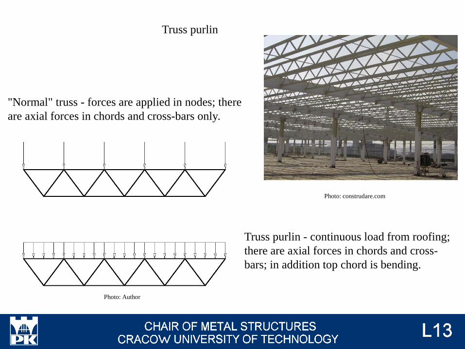
"Normal" truss - forces are applied in nodes; there
are axial forces in chords and cross-bars only.
Truss purlin - continuous load from roofing;
there are axial forces in chords and cross-
bars; in addition top chord is bending.
Photo: Author
Truss purlin
Photo: construdare.com

I-beam purlin: bi-axial bending.
Wind
Dead weight
Snow
Imposed load
a
(D + S + I) cos a + W
(D + S + I) sin a
Wind
Dead weight
Snow
Imposed load
D + S + I + W cos a
W sin a
Truss purlin: horizontal force
W sin a
has very small value and can be neglected
(acts on roofing, not purlins). All loads act in
plane of truss. There is need wedge to install
truss purlin in vertical position.
a
Photo: Author

Recommended types of purlins for different length of span (distance betwen supports):
Lenght Continous,
cold-formed
Continous,
suspended,
cold formed
One-span
hot-rolled
Castellated Truss
< 3
C
D D D
D3 – 4
C4 – 6
C
C6 – 8
D8 – 9
D D C9 – 12
12 – 18D

Photo: Author
Photo: M. Gwóźdź, M. Maślak, Przykłady projektowania wybranych stalowych
konstrukcji prętowych, Politechnika Krakowska 2003
Photo: Author
Support for
purlins
Hot-rolled Cold-formed

Loads:
Dead weight of housing
Dead weight of girt
Wind
Imposed loads
Thermal actions
Accidental actions
Actions durin execution
Girts
Photo: cobouw.pl

Horizontal elements
Vertical elements (for
example additional
columns)
There is no snow load for girts; cross-sections of girts is much more lighter than for purlins.
Photo: calgor.com.plPhoto: everfaithsteel.cnPhoto: newsteelconstruction.com
Photo: wggstal.pl Photo: wistal.pl

Wall girts, purlins, roof bracings and side wall
bracings make specific system for wind action.
Front wall housing columns must be connected
with purlins and roof bracings at one point. The
same, girts on front and side walls.
Photo: steelconstruction.info
Photo: greenterrahomes.com

Wind acts on housing (p, [kN / m2]). Housing is support on
wall girts; loads from housing act on girts as continous
loads (q, kN / m). Girts are under bending (mono- or bi-
axial). Loads from girts act on main frames as forces,
applied in points of connection girts - main columns.
Photo: Author
p
q = p a
al
F = q l
Wind acts on front wall: the same way of recalculation p → q → F. Forces are applied to
main frames (perpendiculary to theirs plane) and to housing columns. In case of doors (in
front / side wall), wind action from door is applied to girts and housing columns around
doors.
Photo: Author

Loads from housing columns finally act on bases of housing
column and main frames (main golumns, roof girders),
perpendiculary to theirs planes. It potentially makes bi-axial
bending in main frames.
Photo: Author
Main frames are supported in
perpendicular direction by bracings,
purlins and side wall girts. It prevent
from bi-axial bending.
Photo: Author
Roof bracings and purlins make horizontal truss. Roof girders are
chords of truss. The effect is, that loads perpendicular to main
frames make additional axial forces in roof girders. Additionally,
there are axial forces in purlins.

Roof: loads are transported through longitudinal broof bracings.
Wall: loads are transported by side wall girts.
Photo: Author
Photo: Author
Finally, loads act on vertical bracings on side walls, vertical trusses. Main columns are
chords of truss. Depending on location of girts on side walls, there is possible bi-axial
bending in these four of columns (loads out of nodes of truss).

Bracings - recommended cross-sections
(→ Lec # 15)
Photo: stalhart.pl
Photo: calgor.com.pl
Photo: rafstal-inox.pl
Photo: rafstal-inox.pl
Photo: EN 1993-1-1 fig. 6.13

Chords : hot-rolled I-beams or pipes
Truss bracing: pipes
Each element at Ist or IInd classs of cross-section
Modern trusses
(→ Lec # 13, 14)
Photo: wikipedia

Beams, girders and columns
(→ Lec # 16-19)
Photo: metroland.com.au
Photo: traskostal.pl

Hot rolled:
I H
IP HE
IPN IPE, IPE-A, IPE-AA IPE-O HEB, HEA, HEAA, HEM
Photo: hmsteel.plPhoto: hmsteel.pl
Photo: optimax.pl
→ Lab #1 / 44

Proportion of cross-sections
Cross-sections Jz / Jy
100 - 300 > 300
IP ~ 1 / 13 ~ 1 / 13 - 1 / 30
HE ~ 1 / 3 ~ 1 / 3 - 1 / 40
Photo: hmsteel.pl

IP HE
NEd C
My, Ed C
Mz, Ed D
My, Ed + Mz, Ed C C
NEd + My, Ed C
NEd + Mz, Ed D C
NEd + My, Ed + Mz, Ed D C
For which type of loads are recommended different types of cross-sections:

L < 25 - 30 m → hot rolled I-beam IP
L > 25 - 30 m → welded I-beam IK
Frames for steel halls
Photo: setrometalgroup.com
Photo: traskostal.pl

Beams, girders → hot rolled IP, welded IK
Colums → hot rolled IP, HE, welded IK, HK
Steel skeletons (3d frames)
Photo: metroland.com.au

Φ
M
Joints
For joints important is their stifeness (relationship M-F)
Photo: Author
Theory:
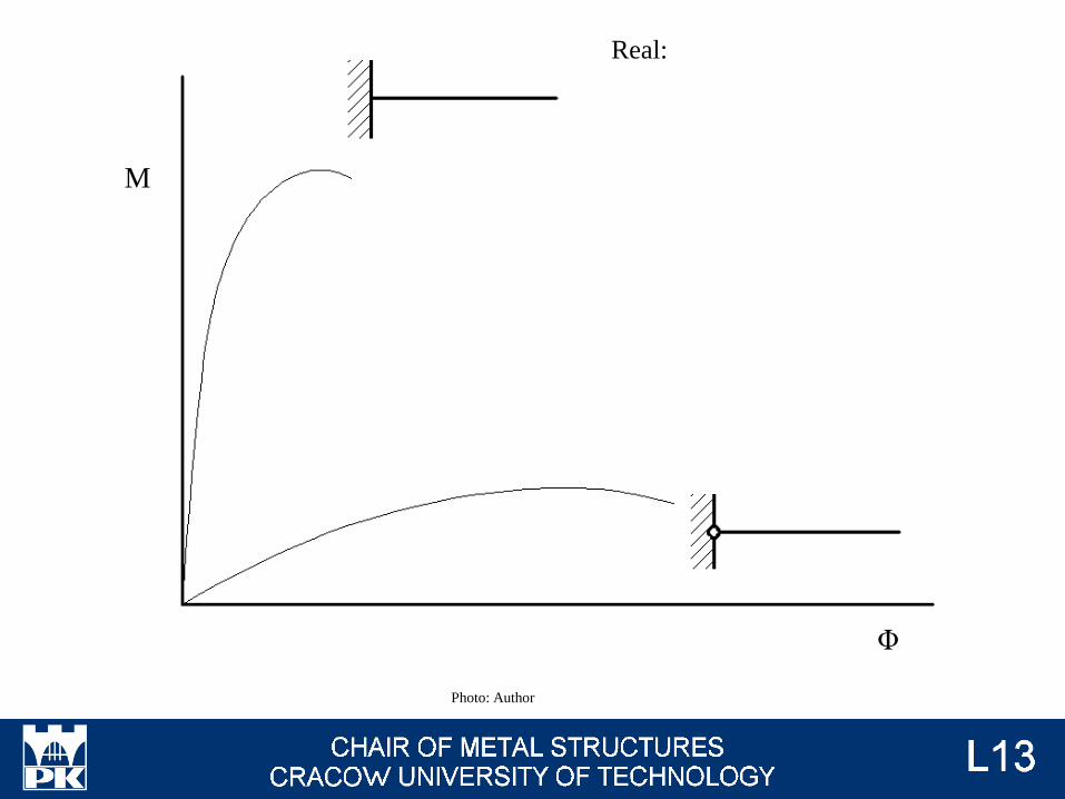
Φ
M
Real:
Photo: Author

Calculations (→ Lec # 20, 21):
What are limits 1-2 and 2-3?
What is stiffness of analysed joint?
What about comparison between limits and stiffness?
Photo: EN 1993-1-8 fig 5.4
Range 1
Range 3
Photo: Author
Range 2

Bolted joint
Welded joint
Information about differences between these two types of joint will be
presented on lecture #7.
Photo: ventia.pl
Photo: stelmet.net
→ Des #1 / 3

Quasi-welded joints (→ Lec # 8)
Soldering - additional metal only
Pressure welding - fusion in few points only
Welding - fusion and additional metal
Photo: Author
Photo: stelmet.net

Quasi-bolted joints (→ Lec # 10)
Bolt
Rivet
Pin
Photo: Author
Photo: ventia.pl

Aspect Bolted
connection
Welded
connection
Page
Influence of weather J L #t / 62
Susceptibility to worker’s qualifications J L #t / 63 – 64
Combination with other materials J L #t / 65
Possibility to disassembly J L #t / 66
Independence from the electricity J L #t / 67
Destruction of corrosion protection J L #t / 68
Influence on the mechanical properties of the
materialJ L #t / 69
Residual deformation and stress J L #t / 70
Fire J L #t / 71
Versatility of the relative position of plates L J #t / 72 - 74
Uniformity of connection L J #t / 745
Time of connection L J #t / 76
Negative and positive aspects

Weather
Work quality for welded connections is much
more important, than for bolted connections.
Bad weather can significantly
decreases ability of workers → and
quality of welded connections.
Bolted connections are not such
susceptible.
Photo: pytamy.wp.pl
Photo: blog-medyczny.pl
Photo: kobieta.onet.pl
Photo: polskiekrajobrazy.pl

Workers qualifications
Everybody can put bolts in holes and screw...
(almost everybody)
Photo: metalmeet.com
Photo: pinterest.com

...but only a small part of people can make welds of high quality.
Photo: weldingtipsandtricks.com
Photo: bbs.homeshopmachinist.net
Photo: gadzetomania.pl
Photo: weldreality.com
Photo: weldreality.com

Other material
We can't weld steel to concrete. We can join them by bolts.
Photo: Author
Photo: civil-engg-world.blogspot.com

Disassembly
We can disassemble bolted connection without destruction - and use members once again in
other place. There is possible only total destruction in case of welded joints.
Photo: panoramasilesia.pl
Photo: stockfresh.com

Electricity
We can't weld without energy. But we can screw bolts.
Photo: stelmet.net
Photo: narzedzia.pl
Photo: theoildrum.com

Corrosion protection
Protection is destructed by high temperature.
Photo: archinect.com
Photo: wikipedia

Influence on the mechanical properties
Photo: M. Łubiński, W. Żółtowski, Konstrukcje
Metalowe t. II, Arkady, Warszawa 2004

Residual stresses and strains (→ Lec # 8)
There are non-zero value of stress and strain after welding.
Photo: M. Łubiński, W. Żółtowski, Konstrukcje
Metalowe t. II, Arkady, Warszawa 2004
Photo: intechopen.com

Fire
Photo: safetylifethailand.com
Photo: kaieteurnewsonline.com

Relative position of plates
~100 and more years ago, I-beams were constructed as plates connected
by L-sections and rivets.
Photo: wikipedia

L-sections enable to joint elements by angle 90o only.
Flat bars enable to joint elements by angle 0o only.
CHS can’t be conected.
Photo: Author
Photo: fotoszoko.blox.pl
Photo: tuwroclaw.com

Because of welding, we can connect members by various angles. We can
connected CHS, too.
Photo: whatsontheare.com
Photo: weiku.com
Photo: tboake.com
Photo: tatasteelconstruction.com

Uniformity
We can't notice borders between elements in well-done weld.
Photo: roadking.riders.pl
Photo: weldingtipsandtricks.com
Photo: bakertesting.com

Time
Sometimes we need much more time to put and screw bolts than to make welds.
Photo: steelconstruction.info

From assemby room to construction site
Steel structures are made by members, welded in assembly room and connected on
construction site by bolts.
Photo: Author

Assembly room → welded connections Construction site → bolted connections
no weather influence;
specialized companies → high workers
qualifications;
possibility of accuracy reconstruction of
corrosion protection;
possibility of wide range of NDT of welds;
possibility of annealing (reduction of welded
stresses and strains);
good fire protection;
no susceptibility on weather;
everybody (even CEO) can connected
members by bolts;

Structure will be transported in pieces from assembly room to construction site. This means,
already at the design stage, designers must think about structure as about complex of transport
members. There must be predicted and designed splice joints between transport members.
Photo: Author Photo: rolstal-hale.pl
Photo: nh-trans.eu

Design project should be idiot-proof.
Photo: Author
There are two identical steel columns. Beam is attached only to one of them, but both have in
the same place transverse stiffeners. It does not matter, if someone makes a mistake and turn
columns places. Both will fit into the rest of the structure.
Members of structures should be unified.

Photo: Author
Design documentation:
Initial drawing - first concept of structure, important for designer (for internal use only). Based
on its, designer calculate loads, length of members and splice joints.
Overall drawing - official global drawing of structure. Important for workers on construction
site. There are presented most important dimensions and names of members. Generally, can
look the same as initial drawing.

Photo: Author
Workshop drawing - drawing of transport member. Important for workers in assembly room
(diameter of holes for bolts, type and length of welds, dimensions of components of transport
member).
Assembly drawing - drawing of splice joints. Important for workers on construction site (type
of bolts, type and length ow welds if there are welded splice joints).
For small structures, both
imformation can be
presented on one drawing.

List of materials:
Photo: Author
• Total mass of structure →
cost of material;
• Mass of transport members
(modulus) → cost of transport;
• Mass of welds, bolts and
moduluses → labor cost.

Trial erection in assemby room before transport to construction site: check geometry.
Photo: steelkonstruction.info
Photo: panama.uela.it
Errors or mistakes are repaired after this step.

Transport:
• by road
• by rail
• by ship
• by helicopter
• on foot
Photo: lotnictwo.netPhoto: rent-helicopters.com
Photo: dailymail.co.uk
Photo: inbud.pl
Photo: flickriver.com

Road loading gauge 12,00 m
Length of the I-beams produced 12,00
(sometimes 15,00) m
Rail loading gauge
18,00 m
Length of elements: beams - to few dozens m;
columns - to few hundreds m
Why this type of joint is used?
Photo: Author
→ Des #1 / 7

Photo: petronor.eus
We can transport even enormous huge structures, but it is very, very expensive (closing
road for normal traffic, organisation bypass, monitoring of transport). Because of this,
better way is transport not very big members of structure.

There are three types of limits according to loading gauge:
• max width of member;
• max length of member;
• max mass of member;
Max with of member depends on class of road or
railroad:
Photo: drogi.com
Photo: kolej.krb.com.pl
Max length for rail and road is defined by few law rules.
Max mass depends, first of all, on capacity of truck or rail platform.

Additionally, there are
important many local
limits.Photo: sklepdrogowy.pl
Photo: Author
Assembly room
Construction site
Transport by rail is more popular than transpotr by
ship, air or on foot. But, because only a part of
assemby rooms and construction sites are next to
railroad, the most popular is tranport by cars.
Photo: profinfo.pl

According Road Traffic Law, we no need additional permissions, when each total dimensions
(structure + vehicle) are not exceeded:
• width ≤ 3,20 m;
• length ≤ 15,0 m (one vehicle) or ≤ 23,0 m (team of two vehicles) ;
• height ≤ 4,0 m;
• axe load ≤ 11,5 t;
Generally, there’s no problem, when
transport membes is no longer than
12,0 m in road transport and 18,0 in
rail transport.
Photo: leosped.eu

Construction site: there must be analyse, how many cranes and what kind we need to
erected structure. Two most important information about crane are length of arm and
lifting capcity.
Photo: focus.pl
Photo: najem-wynajem.pl
Photo: willbros.com

Assembly anchoring of steel column:
stabilization and plumbing on bolts or steel
wedges and plates.
Photo: studio-tm.com
Photo: inzynierbudownictwa.pl
Photo: elcosh.org
Then the gap between structure and concrete
base is primed by mortar.

Assembly of structure – first step: mounting the first and the second segment with the
temporary supports.
Photo: spaceevanston.blogspot.com
Photo: srt251clji.blogspot.com

Second step: two adjacent frames (first and second segments) connected by bracings
form of a rigid body, to which are being added to next frames.
Photo: makosz.com.pl
Last step: hall is enclosed by
roofing and housing.

There is possible of change static
scheme during execution of structure.
Photo: eaglecrane.ca
Photo: Author
For example: vertical longitudinal
bracings work for wind load in execution
stage. Final area of wind action (covered
structure) and temporary - not covered
truss - there are two completely different
areas.
Photo: aecom.com

The element is often not protected against
instability during lifting by crane. Clumsy
transport can lead to flexural, torsional and
lateral buckling.
Photo: helpstud2.narod.ru
Photo: wisegeek.com
Photo: Author
a
gR = g L / (2 sin a)
Mmax = g L2 / 8
R = g L / (2 sin a)
Nc = (g L cos a) / (2 sin a)

Negative and positive aspects of bolted and welded connections
Transport members, ways of transport and their limitations for transport
Examination issues

Pilings - palowanie, grodze
Roofing - poktycie dachu
Housing - obudowa ścian
Wall laminboard / sandwich panel - panel obudowy ściennej
Self-tapping screw - wkręty samogwintujące
Purlin - płatew
Rigging screw - śruba rzymska
Girt - rygiel obudowy
Castellated beam - belka ażurowa
Closely spaced build-up members - pręt wielogałęziowy
Frame - rama
Girder - dźwigar
Pinned joint - węzeł przegubowy
Rigid joint - węzeł sztywny
Semi-rigid joint - węzeł podatny
Welding - spawanie
Pressure welding - zgrzewanie
Soldering - lutowanie
Bolt - śruba
Rivet - nit
Pin - sworzeń
Anchor bolt - kotew
Plumbing - wypionowanie
Mortar - zaprawa