Metal Structures Lecture VI Imperfections - footbridge.plfootbridge.pl/stud/z/se1/lec106.pdf ·...
99
Metal Structures Lecture VI Imperfections
Transcript of Metal Structures Lecture VI Imperfections - footbridge.plfootbridge.pl/stud/z/se1/lec106.pdf ·...

Metal Structures
Lecture VI
Imperfections

Contents
Introduction → #t / 3
Structural imperfections → #t / 13
Geometrical imperfections and technical requirements → #t / 36
Execution classes → #t / 50
Design proces → #t / 60
Example → #t / 85
Examination issues → #t / 97
Introduction
Photo: joemonster.org
Photo: raider55.blog.pl

Photo: fishki.pl
Photo: smartevil111.wordpress.com

Photo: fishki.pl
Photo: demotywatory.pl

Photo: popularne.pl
Photo: prikol.ru

Idiots everywhere?
IMPERFECTIONS
Imperfections everywhere
Photo: fabrykamemow.pl
Photo: hourdose.com

Imperfections in steel structures are rather not such picturesque...
Photo: ccj-online.com Photo: mig-welding.co.uk
Photo: image.slidesharecdn.com
Photo: panama.uela.it

Photo.: Autor
First labratory, measurements:
hI :
524 mm
522 mm
523 mm
525 mm
524 mm
523 mm
524 mm
…
b :
198 mm
202 mm
199 mm
199 mm
200 mm
201 mm
200 mm
…
tf :
11,6 mm
12,2 mm
11,8 mm
11,9 mm
12,0 mm
12,1 mm
11,9 mm
…
tw :
2,88 mm
3,04 mm
3,13 mm
2,77 mm
2,90 mm
2,36 mm
2,48 mm
…
Some of these divergences are measurement
errors. But because of imperfection, the actual
dimensions of the measured I-beam may differ
from the ideal dimensions shown in the design
tables.

We can’t avoid imperfections. In real world not exist ideal structures.
Imperfections origin from microdamages of material, from uncertainly of mathematical models used for calculations and from human factor (confusions, errors).
Part of them we eliminate because of technical requirements for prefabrication process or for erection of structures. Next part of them we can remove by heat treating. Rest of them
we must taken into account during calculations.
For calculations we take ideal geometry (no geometrical imperfections), ideal material (no structural imperfections) and additional load schemes and dimensionless parameters,
which represent real imperfections.

Photo: Author

Imperfections can be divided into two groups:
structural
geometrical
Photo: Author

Analysis of material
Structural imperfections
Structural imperfections can be divided into two kinds:
• natural features of material;
• secondary effects of material processing (hot-rolling, cold-forming, cutting to requireddimensions, welding…)

Natural features of material
1. For metals, molecular structure is important. We have no ideal crystals – lack of molecule, shift of molecules, molecules of other chemical elements. Each of these situation
changes internal structure of metal and locally decreases its mechanical parameters.
Photo: wikipedia

2. Crystals form in random places and in random directions. Their dimensions have random values. Microstresses and microdamages concentrate on borders of crystals.
Photo: zasoby.open.agh.edu.pl

3. Ferrite, austenite, cementite, ledeburite,
pearlite, martensite, bainite, sorbite,
spheroidyte – different forms of steel
have different mechanical parameters.
Steel consist from iron and carbon – as mixture or chemical compound. Additionally, there are different types of crystals. The effect: various local strength in various
points of element.
Photo: wikipedia
Photo: wikipedia

4. Pollutions
Inside each type of steel exists microscopic impurities of sulphur, phosphorus, gases and slags. They have destructive influence on mechanical parameters of steel
(corrosion, microcracking)
C Mn Si P
(max)
S
(max)
Cr Ni Cu
(max)
Al N
(max)t < 16
mm
16 < t <
40 mm
t > 40
mm
0,170 0,170 0,200 1,400 0,000 0,035 0,035 0,000 0,000 0,550 0,000 0,012
S 235 JR [%]

Effect: different speciments of steel can have different mechanical parameters = different amount of microdamages in different part of material
Photo: Author
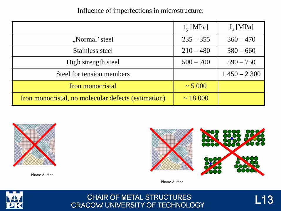
fy [MPa] fu [MPa]
„Normal’ steel 235 – 355 360 – 470
Stainless steel 210 – 480 380 – 660
High strength steel 500 – 700 590 – 750
Steel for tension members 1 450 – 2 300
Iron monocristal ~ 5 000
Iron monocristal, no molecular defects (estimation) ~ 18 000
Influence of imperfections in microstructure:
Photo: Author
Photo: Author

tw ≠ tf
DTw / tw ≠ DTf / tf [oC/s]
Secondary effects of material processing
1. Hot-rolled cross-section: different thickness of web and flange, but the same temperature. Rate of temperature decreasing is different. Because of this, thermal stresses occur. This is type of residual stresses. Non-zero values of residual stresses change behaviour of member
under loads.
Photo: Author
Photo: preetgroup.com

Residual stresses are self-balanced: each cross-sectional forces caused by them (axial force, bending moment, shear force, torsional moment) are equal 0,00 but their local values could be very big. Their sum with stresses from loads could be locally equal strength of material even for not big value of loads. This phenomenon could significantly decreases resistance of cross-section in comparison to teoretical assumption about lack of stresses in not-loaded element.
Photo: Global sensitivity analysis of lateral-torsional buckling resistance based on finite
element simulations, ZdeněkKala JanValeš

2. Similar situation: cold-formed cross-sections; big deformations during formation of shape of cross-section. The same situation: non-zero values of self-balanced residual stresses.
Photo: Author
Photo: Design of cold-formed steel structures, D. Dubina, V. Ungureanu, R. Landolfo
Photo: ciecieplazma.pl

Plates and quasi-plates:
Photo: steelstrap.en.ecplaza.net
Photo: corten.com
Hoop iron (t = 1-5 mm; s = 20-85 mm)
Flat steel (t = 6-55 mm; s = 20-150 mm)
Photo: threadedstainlesssteelpipe.com
Plate in coils
Plate sheets
Photo: corten.com
→ #1 / 74

Plate sheetss:
Flat
Photo: corten.com
Photo: checker-plate.com
Riffled
Flat plate sheetss:
• cut from the coils;
• rolled in one direction;
• rolled in two directions (universal plate); Photo: Author
→ #1 / 75

4. Crystals are deformated during rolling.
This deformation followed by one direction.
Steel plates rolled in one direction can have
different mechanical characteristics in both
directions.
Photo: Author Photo: paws.wcu.edu
Photo: threadedstainlesssteelpipe.com
3. Plate in coils: plates must be straight from the roll after
transport. The effect are plastic deformations and residual
stresses.
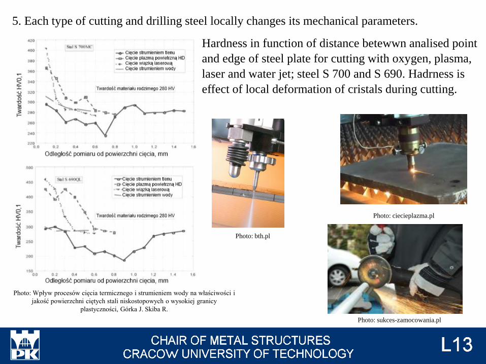
Photo: bth.pl
Photo: Wpływ procesów cięcia termicznego i strumieniem wody na właściwości i
jakość powierzchni ciętych stali niskostopowych o wysokiej granicy
plastyczności, Górka J. Skiba R.
5. Each type of cutting and drilling steel locally changes its mechanical parameters.
Hardness in function of distance betewwn analised point
and edge of steel plate for cutting with oxygen, plasma,
laser and water jet; steel S 700 and S 690. Hadrness is
effect of local deformation of cristals during cutting.
Photo: ciecieplazma.pl
Photo: sukces-zamocowania.pl

Initial deformations during cutting (type of plastic deformation) of steel plate – another
effect of local deformations of cristals.
Photo: steelconstruction.info
Photo: ndt.net
Hardened steel is very susceptible to brittle fracture. Each element on all cut edges has a certain amount of microcracks.

6. Welded elements: different temperature for different part of elements, different thermal deformations. Non-zero value of residual stresses.
Photo: Author
T = 20 oC T = 1 500
oC
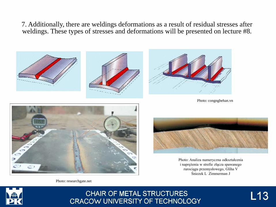
7. Additionally, there are weldings deformations as a result of residual stresses after weldings. These types of stresses and deformations will be presented on lecture #8.
Photo: congnghehan.vn
Photo: researchgate.net
Photo: Analiza numeryczna odkształcenia
i naprężenia w strefie złącza spawanego
rurociągu przemysłowego, Gliha V
Śniezek L Zimmerman J

8. The side effect of the local remelting of the material is the re-crystallization process. This
causes local changes in the mechanical parameters of the material.
Photo: Konstrukcje stalowe, K. Rykaluk,
Dolnośląskie Wydawnictwo Edukacyjne
Wrocław 2001
Photo: struers.com

9. Last reason of imperfections during welding process: secondary pollutions and
microdamages. This is the reason for the greatest number of imperfections.
Photo: manufacturingscience.asmedigitalcollection.asme.org
The number of imperfections generated
during welding proces is much greater than
during other machining processes.

Approximation: average number of imperfections:
„normal” structural imperfections in steel plate
effect of material processing (cuting, making holes…)
effect of welding process
Photo: scottmetals.com.au
Photo: Author
Photo: Author
Example: bar bracing with gusset plate

Structural imperfections in steel plate (#t / 14 – 19)
Additional effects of material processing (#t / 20 – 27): plastic deformations, local hardening
of steel, local cracking…
Photo: wikipedia
Photo: omicsonline.org
Photo: zasoby.open.agh.edu.pl
Photo: pmpaspeakingofprecision.com

Additional effects of welding process (#t / 28 – 31): secondary pollutions (gas bubbles, ash)
introduced during welding, local deformation of plates, cracks as effect of thermal shrinkage...
Photo: figel.pl
Ability and experience of worker ↓ → number of welding imperfection ↑ → quality level of
welds ↓
Accepted number of welding imperfection is limited by Execution Class. (→ #t / 50).

Annealing – increasing of temeprature, keeping element in this temperature for long time (it’s need to change internal structure), very slow decreasing of temperature;
Annealing 1100o C → homogeneous internal structure (chemical and crystalline), homogenize the mechanical characteristics;
Annealing 800 - 100o C → fragmentation of crystals, increasing strength;
Annealing 500 - 600o C → reduction of residual stresses;
Quenching – increasing of temeprature, keeping element in this temperature for long time (it’s need to change internal structure), very quick decreasing of temperature → increasing hardness and fragility;
Tempering – increasing of temeprature, keeping element in this temperature for long time (it’s need to change internal structure), slow decreasing of temperature;
Tempering 600o C → high strength, decreasing hardness;
Tempering 400o C → high strength, high plasticity, decreasing hardness;
Tempering 200o C → reduction of quenching stresses and fragility, high hardness;
More information → lab. #5 → #1 / 89

EN 1090 Execution of steel and aluminum structures:
1090-1 Requirements for conformity assessment of structural components
1090-2 Technical requirements for steel structures
1090-3 Technical requirements for alumnium structures
Geometrical imperfections and technical requirements
How big values of deformations are acceptable?
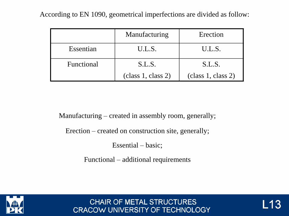
Manufacturing Erection
Essentian U.L.S. U.L.S.
Functional S.L.S.
(class 1, class 2)
S.L.S.
(class 1, class 2)
According to EN 1090, geometrical imperfections are divided as follow:
Manufacturing – created in assembly room, generally;
Erection – created on construction site, generally;
Essential – basic;
Functional – additional requirements

Examples of Essential – Manufacturing
Photo: EN 1090-2 tab. D.1.1

Photo: EN 1090-2 tab. D.1.1

Photo: EN 1090-2 tab. D.1.2

Photo: EN 1090-2 tab. D.1.5

Photo: EN 1090-2 tab. D.1.7

Examples of Essential – Erection
Photo: EN 1090-2 tab. D.1.11

Examples of Functional – Manufacturing
Photo: EN 1090-2 tab. D.2.1

Examples of Functional – Erection
Photo: EN 1090-2 tab. D.2.23

Photo: EN 1090-2 tab. D.2.24

Example
h = 800 mm
Class D Manufacturing Erection
EssentialNot
applicable
+ 0 mm
Not applicable
- h / 50 = 16 mm
Functional
1
+ 3 mm
- 3 mm
2
+ 2 mm
- 2 mm
Conclusion: +0mm, -2 mm or -3 mm according to class
Photo: EN 1090-2 tab. D.1.1

The dimensions of the bolts are subject to other standards. The minimum and maximum allowable dimensions are given, for
example, in the design tables.
Photo: Tablice do projektowania konstrukcji metalowych, W. Bogucki, M. Żyburtowicz

EN 1993-1-1 2.4.2 (1)
If geometrical imperfections do not exceed the permissible values, nominal dimensions are assumed for the calculation (assumed in the design project).

Consequences classes CC1 CC2 CC3
Service categories SC1 SC2 SC1 SC2 SC1 SC2
Production
categories
PC1 EXC1 EXC2 EXC2 EXC3 EXC3 EXC3
PC2 EXC2 EXC2 EXC2 EXC3 EXC3 EXC4
Class of imperfection 1 2
There are two classes of imperfections for functional geometrical imperfections. They
depend on execution class.
What is the way to determine type of execution class?
EN 1090-2 tab B.3
If we can't make accurate analysis, we assume EXC2.
Execution class
II
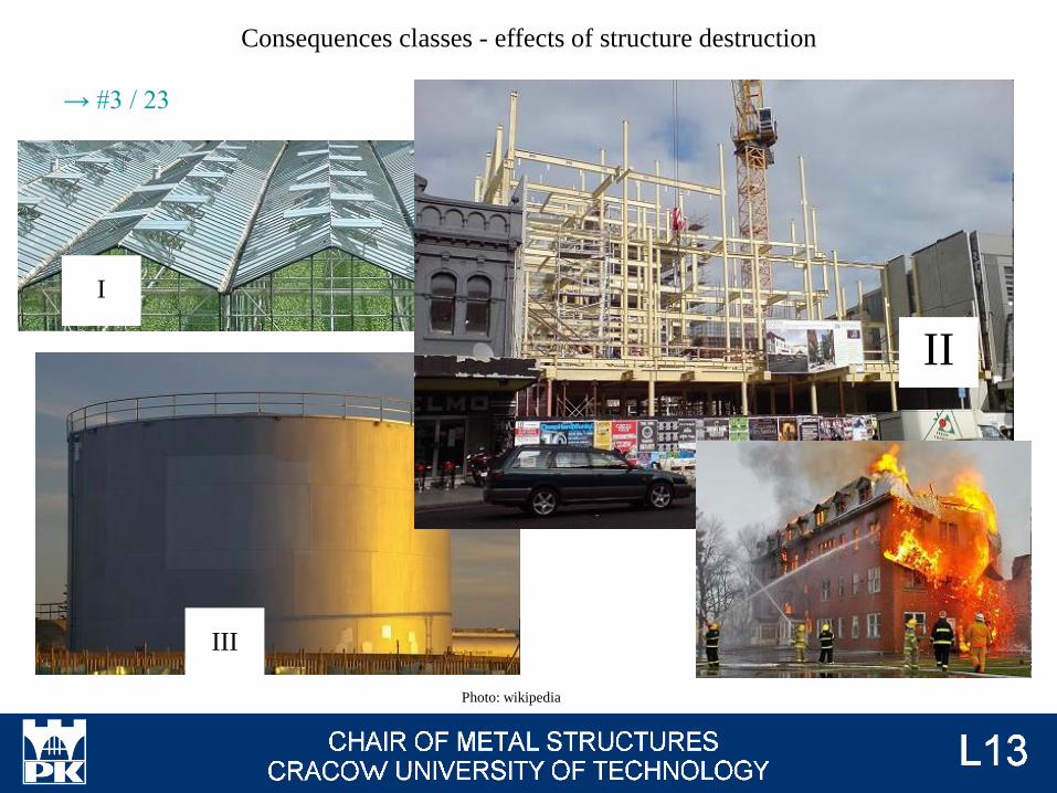
Consequences classes - effects of structure destruction
III
I
Photo: wikipedia
→ #3 / 23

EN 1990 tab B1
Consequences
calsses
Description Examples
CC3 High consequence for loss of
human life
or
economic, social or environmental
conequences very heavy
Grandstands; public buildings where
consequences of failure are high
CC2 Medium for loss of human life
or
economic, social or environmental
conequences considerable
Residential; office buildings; public
buildings where consequences of failure
are medium
CC1 Low for loss of human life
and
economic, social or environmental
conequences small or neglegible
Agricultural buildings where people do
not normally enter; greenhouses
→ #3 / 24

Service categories: EN 1090-2 tab. B.1
Categories Criteria
SC1 Structures and components designed for quasi static actions only (example:
buildings);
Structures and components with their connections designed for seismic actions in
regions with low seismic activity and in DCL*;
Structures and components designeg for fatigue actions from cranes (class S0)**;
SC2 Structures and components designed for fatigue actions according to EN 1993
(examples" roads and railway bridges, cranes (class S1 to S9)**, structures
susceptible to vibrations induced by wind, crowd or rotaring machinery);
Structures and components with their conections designed for seismic actions in
regions with medium or risk seismic activity and in DCM* and DCH*;
* DCL, DCM, DCH: ductility calsses according to EN 1998-1;
** For classification of fatigue actions from cranes, see EN 1991-3 and EN 13 001-1

Production categories: EN 1090-2 tab. B.2
Categories Criteria
PC1 Non welded components manufactured from any steel grade products;
Welded components manufactures from steel grade products below S355;
PC2 Welded components manufactured from steel grade products from S355 and
above;
Components essential for structural integrity that are assembled by welding on
construction site;
Components with hot forming manufacturing or receiving thermic treatment
during manufacturing;
Components of CHS lattice girders requiring end profile cuts;

Execution classes Quality level for welded joints
EXC1 D
EXC2 C (generally)
D (undercut, overlap, stray arc, end crater pipe)
EXC3 B
EXC4 B+
Welds quality as a function of Execution Class (EN 1090-2 tab 7.6)

EN ISO 5817 tab. 1 - limits of imperfections for quality level
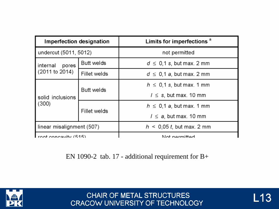
EN 1090-2 tab. 17 - additional requirement for B+

EN 1090-2 tab. 24 – range of non-destructive tests (NDT), for example X-ray,
made for determining the real level of imperfections.
For good-quality weld: real level of imprerfections limit.
Otherwise weld must be deleted and made once again.

Consequence Class
Reliability Class
Service Categories
Production Categories
Execution Class
Geometrical Imperfection
Class
Design Supervision
Level
Inspection Level
Photo: Author
Quality level of welds
Accepted values of geometrical imperfections
Supervision during design
Supervision during
erection
Safety factors for
loads
A system to minimize
the possibility of error
during design proces
A system to minimize
the possibility of error
during manufacturing
and erection
Differentiation of
loads for more or less
important structures
System protection of the structure against errors and imperfections includes design,
manufacturing and assembly. For the more responsible structure (CC ↑ SC ↑ PC ↑ ) high
quality of welds, small geometrical imperfections and detailed supervision of design and
assembly are necessary.
Welds with too low quality or elements with too big imperfections must be removed and
made again.
Design proces
Imperfections are taken into consideration in many various way during design proces.
Generally: we analyse ideal geometry, ideal material and effect of imperfections by one of
few methods.
These methods can be divided as follows:
• general principles for design and erection, based on the experience of many generations of
engineers;
• additional parameters describing the impact of imperfection on the material;
• indirect consideration of imperfections in calculations;
• equivalent loads from imperfections in calculations.
Equivalent forces are based on geometry of structure and cross-sectional forces in elements.
The cross-sectional forces are calculated taking into account the safety factors g for loads.
Therefore, equivalent forces do not have to be multiplied once again by the factors g.
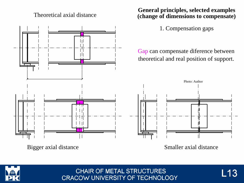
Gap can compensate diference between
theoretical and real position of support.
Bigger axial distance Smaller axial distance
Theoretical axial distance
Photo: Author
General principles, selected examples (change of dimensions to compensate)
1. Compensation gaps

Effect of compensation: bolts holes in I-beam
and plates are in different places.
Photo: Author
Because of this, slotted holes are applied in
steel structures.
Photo: tekla-detailed-structural-fabrication.com
Oversize and slotted holes are not accepted fot preloaded bolts. Better solution are
holes made on construction site, after measuring the actual bolts position.
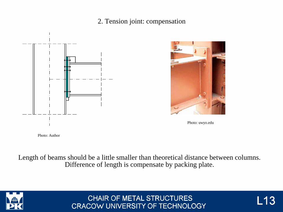
2. Tension joint: compensation
Photo: Author
Photo: uwyo.edu
Length of beams should be a little smaller than theoretical distance between columns. Difference of length is compensate by packing plate.

Accuracy for steel structures - to 1 mm. Accuracy for concrete structures (also for position of
anchor bolts) - to 10 mm. Diameter of hols for bolts must be very big to enable compensate
imperfection for position of anchor bolts.
Photo: Author
Photo: nees.org
3. Support of columns

5t5t
t
There are zones of residual stress concentration for different types of cross-sections. We should avoid or limit welds on black parts of cross-sections.
It’s important for geometry of welds.
Photo: Author
4. Recommendations for welds

Theoretical weld quality by mathematical model
Initial part - launch of
the welding machine Final part - possibility
of premature shutdown
Real weld quality
Real weld quality by mathematical model - too short weld in comparison to load
Weld qualityPhoto: Author
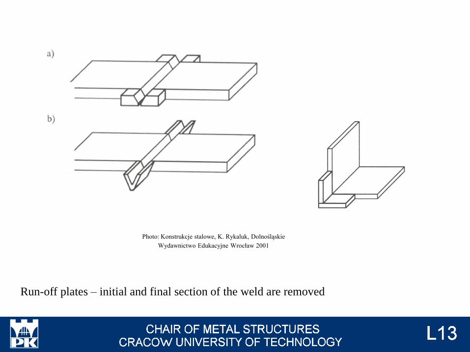
Run-off plates – initial and final section of the weld are removed
Photo: Konstrukcje stalowe, K. Rykaluk, Dolnośląskie
Wydawnictwo Edukacyjne Wrocław 2001

a
2a
2a
l
a
l(calculations) = l or l - 2a or l + 2a - 2a
Filled welds – length of welds without run-off plates
Photo: Author

Additional parameters
1. Safety factors
Photo: EN 1990 fig. C3
Uncertainty in material propertiws means unknown influence of material imperfections
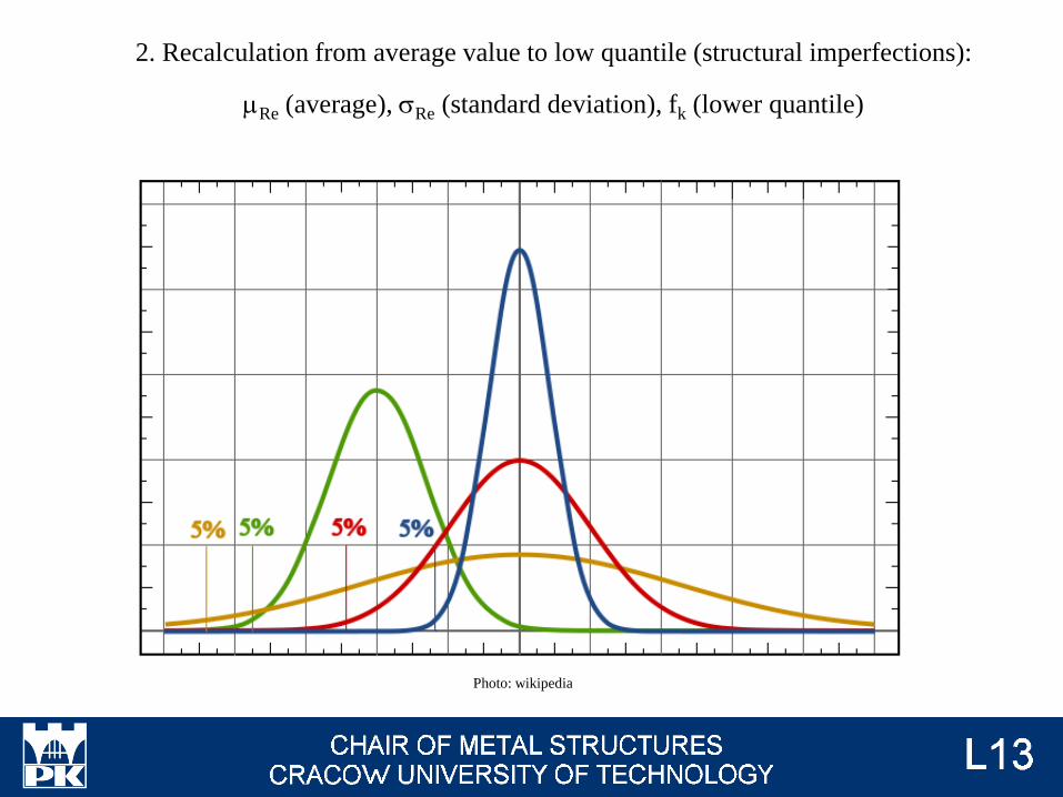
2. Recalculation from average value to low quantile (structural imperfections):
mRe (average), sRe (standard deviation), fk (lower quantile)
Photo: wikipedia
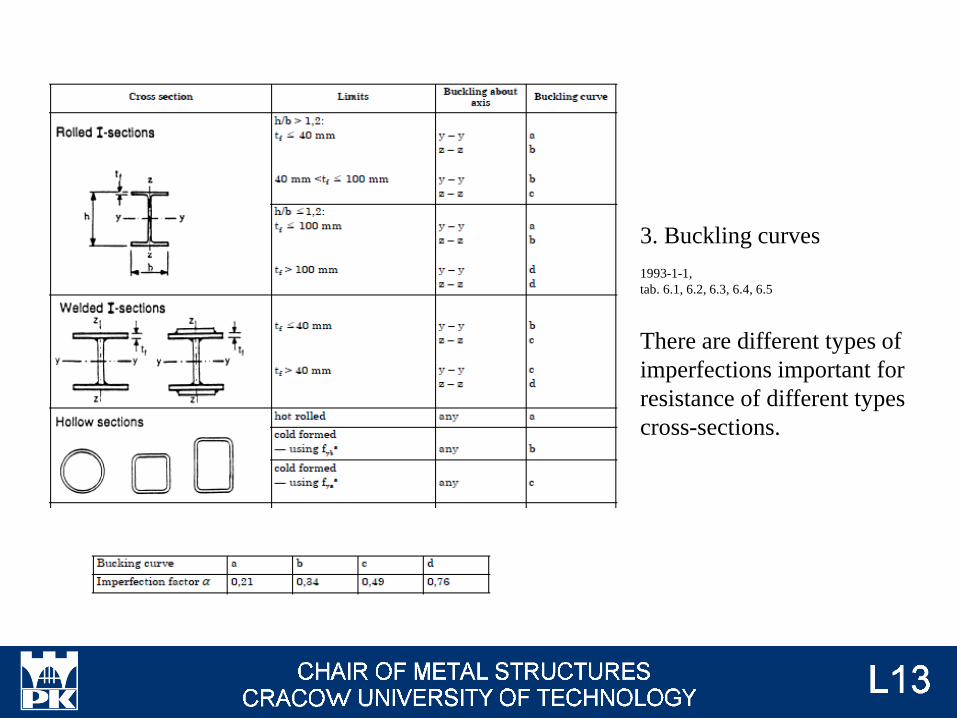
3. Buckling curves
1993-1-1,
tab. 6.1, 6.2, 6.3, 6.4, 6.5
There are different types of
imperfections important for
resistance of different types
cross-sections.

Imperfections affect the behavior of the compression bars. Generally: increasing of
imperfections makes less critical force and the resistance to instability.
Photo: chodor-projekt.net
1 – axial compression
2 – axial compression + bending due
to eccentricity (imperfection)
Photo: chodor-projekt.net
ideal bar
imperfected bar

Buckling curves according to Eurocode and for ideal
(no geometrical and no material imperfections)
compressed bar.
Photo: Zagadnienia stateczności konstrukcji metalowych,
K. Rykaluk, DWE Wrocław 2012
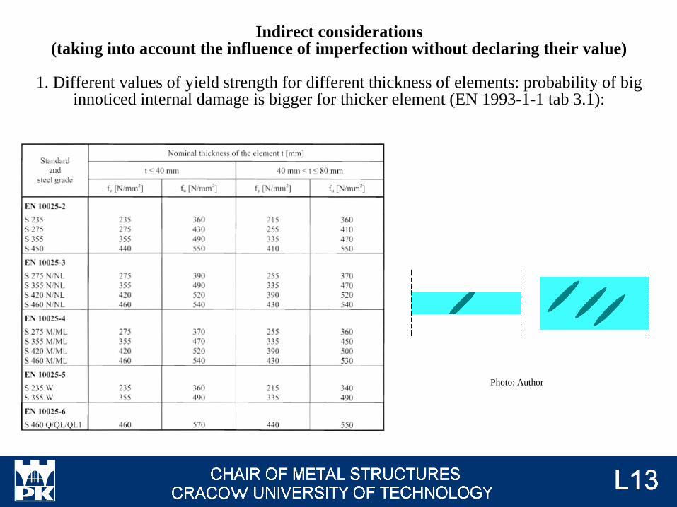
Indirect considerations(taking into account the influence of imperfection without declaring their value)
1. Different values of yield strength for different thickness of elements: probability of big innoticed internal damage is bigger for thicker element (EN 1993-1-1 tab 3.1):
Photo: Author
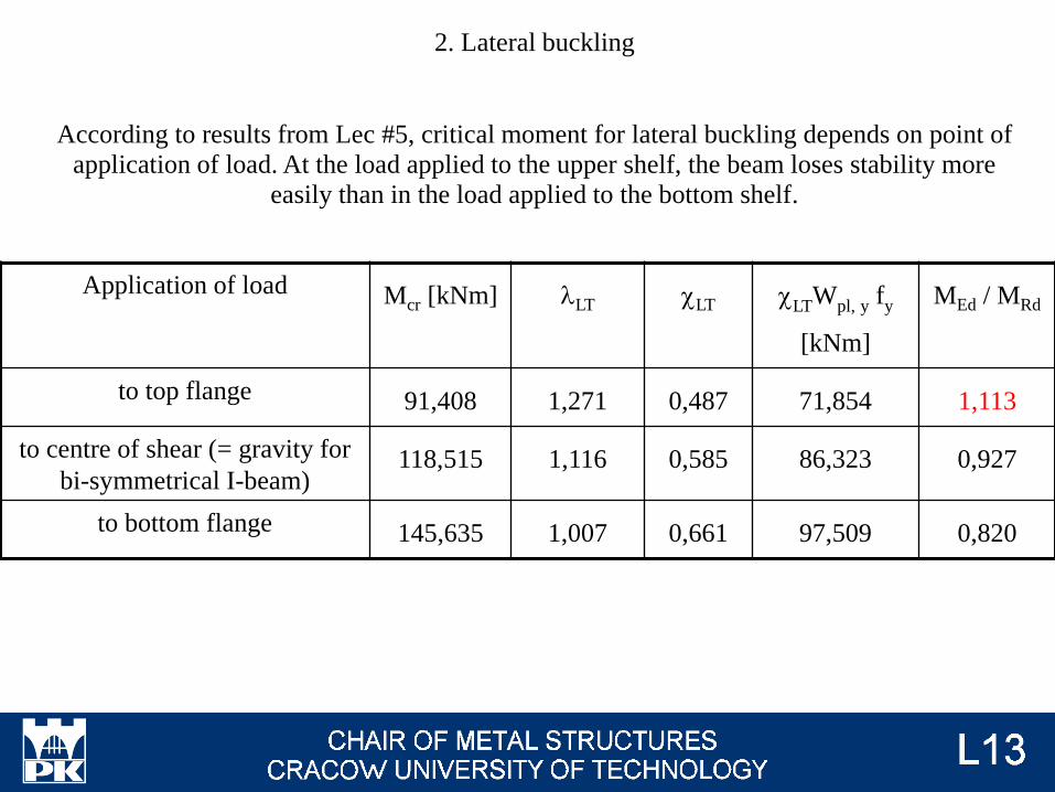
2. Lateral buckling
According to results from Lec #5, critical moment for lateral buckling depends on point of
application of load. At the load applied to the upper shelf, the beam loses stability more
easily than in the load applied to the bottom shelf.
Application of load Mcr [kNm] lLT cLT cLTWpl, y fy
[kNm]
MEd / MRd
to top flange 91,408 1,271 0,487 71,854 1,113
to centre of shear (= gravity for
bi-symmetrical I-beam)118,515 1,116 0,585 86,323 0,927
to bottom flange 145,635 1,007 0,661 97,509 0,820

Photo: Author
Support at the end
Support at the end
Even a small displacement of the load gives
an additional twisting moment, facilitating
the loss of stability.
Imperfections for load on
the bottom shelf are not
such dangerous.

3. Fatigue calculations
Photo: figel.pl
Photo: pmpaspeakingofprecision.com
Imperfections originating from machining (cutting, drilling holes) and re-formed during welding, are notches reducing fatigue resistance. They must be taken into account in the case of high-cyclic and dynamic loads. Initial fatigue resistance, depending on the type of notch
(i.e. its origin), is described in EN 1993-1-11. Initial fatigue resistance decreases with increasing of load cycles number.
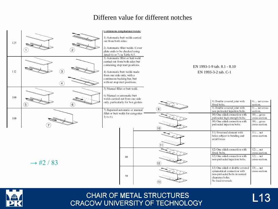
Differen value for different notches
EN 1993-1-9 tab. 8.1 - 8.10
EN 1993-3-2 tab. C-1
→ #2 / 83

laced compression members,
battened compression members,
closely spaced build-up compression members
Direct considerations
(equivalent values of imperfections in formulas)
1. We must analysed initial deformations for members with two or more chords
(according to EN 1993-1-1 p.6.4). This means, these elements are always bent,
even if axial force acts only.
MEdII = eimperf NEd
More information will be presented on lecture #13 and # 19
Photo: EN 1993-1-1 fig 6.13
Photo: EN 1993-1-1 fig 6.7

2. Stiffeners
Because of initial imperfections, we
increase value of axial force and add
prependicular load. Both depend on eimperf
More information will be presented on lecture # 14
Photo: Author
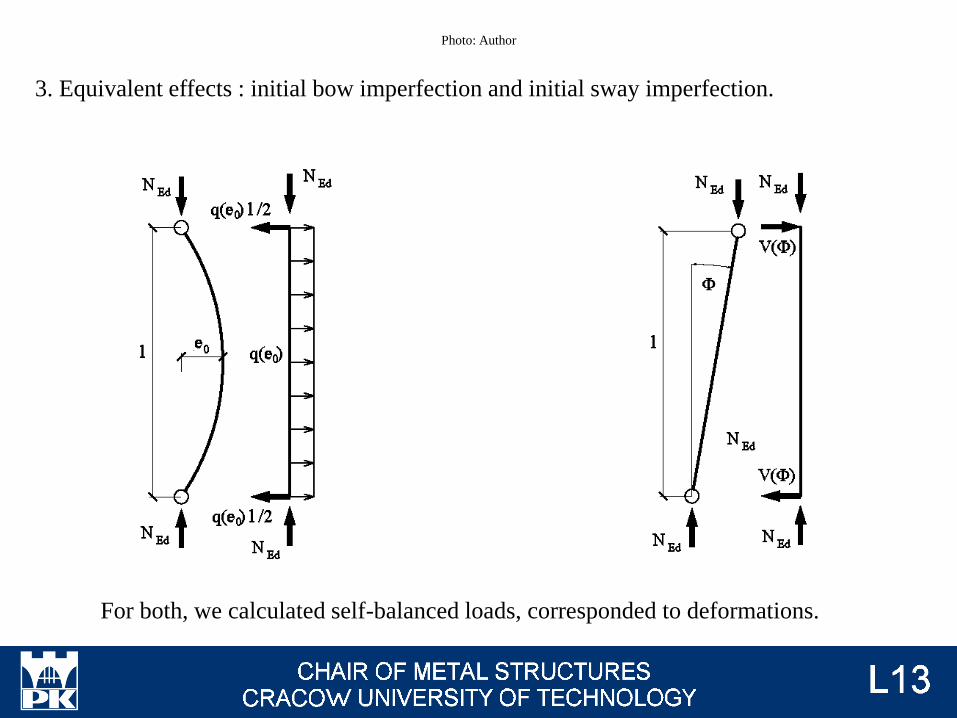
3. Equivalent effects : initial bow imperfection and initial sway imperfection.
For both, we calculated self-balanced loads, corresponded to deformations.
Photo: Author

roof girder, horizontal bracing
(roof)
horizontal bracing (ceiling)or
vertical bracing
columnand (mutually exclusive in
combinations)
We use different models for different members:
Photo: Author

Sway imperfection F = F0 ah am
F0 = 1 / 200
ah = max{ 2 / 3 ; min[ (2 / √h) ; 1,0]}
h – heigh of structure [m]
am = √[ 0,5 (1 + 1 / m)]
m - number of columns (elements) in a row,
including only those columns, which carry a
vertical load NEd not less than 50% of the average
value of the column in the vertical plane
considered
NEd – axial force in column or in braced member
(chord of truss, etc).
V(F) h = M = NEd h F
V(F) = NEd FEN 1993-1-1 fig. 5.4
h
Photo: Author

Bow imperfection
e0 depends on buckling curve (→ Lec #5)
Buckling curve Elastic analysis Plastic annalysis
a0 l / 350 l / 300
a l / 300 l / 250
b l / 250 l / 200
c l / 200 l / 150
d l / 150 l / 100
NEd – axial force in column or in braced member
(chord of truss, etc).
NEd e0 = M = q(e0) h2 / 8
q(e0) = 8 NEd e0 / h2
EN 1993-1-1 fig. 5.4
h
Photo: Author

Comparision of imperfections values [m]
Essentian imperfection - functional imperfection - design imperfection
Sway imperfection for entire structure - sway imperfection for one storey - bow imperfection
Example
Columns HEB 300, S235, buckling about axis y, elastic analysis
Photo: Author
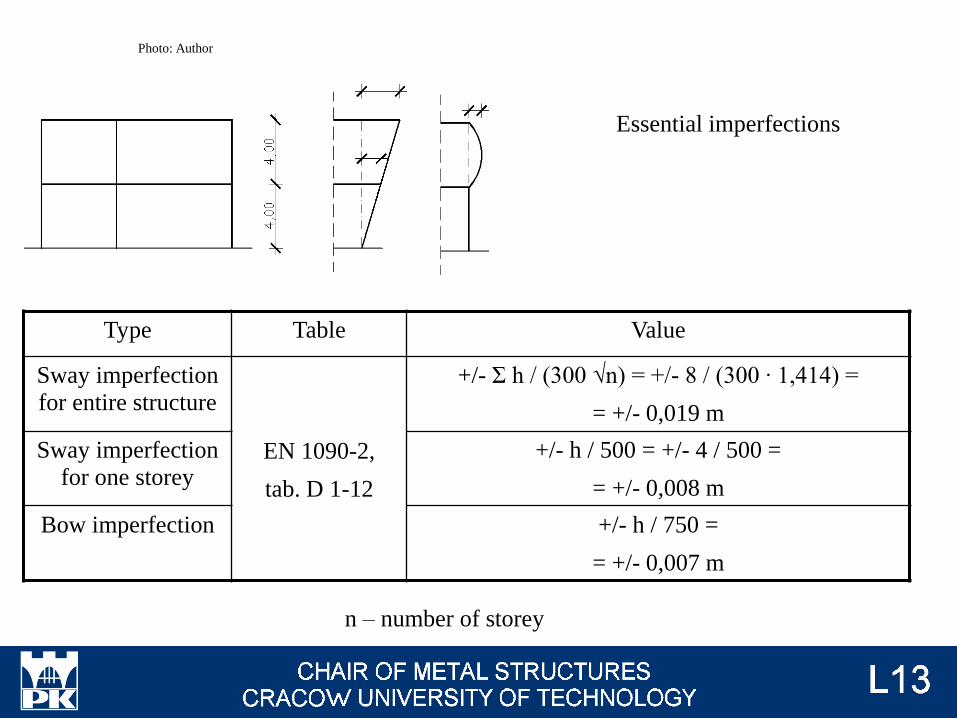
Essential imperfections
Type Table Value
Sway imperfection
for entire structure
EN 1090-2,
tab. D 1-12
+/- Σ h / (300 √n) = +/- 8 / (300 ∙ 1,414) =
= +/- 0,019 m
Sway imperfection
for one storey
+/- h / 500 = +/- 4 / 500 =
= +/- 0,008 m
Bow imperfection +/- h / 750 =
= +/- 0,007 m
n – number of storey
Photo: Author

Functional imperfections,
Class 1
Type Table Value
Sway imperfection
for entire structure
EN 1090-2,
tab. D 2-24
+/- Σ h / (300 √n) = +/- 8 / (300 ∙ 1,414) =
= +/- 0,019 m
Sway imperfection
for one storey
+/- h / 500 = +/- 4 / 500 =
= +/- 0,008 m
Bow imperfection +/- h / 750 =
= +/- 0,007 m
n – number of storey
Photo: Author
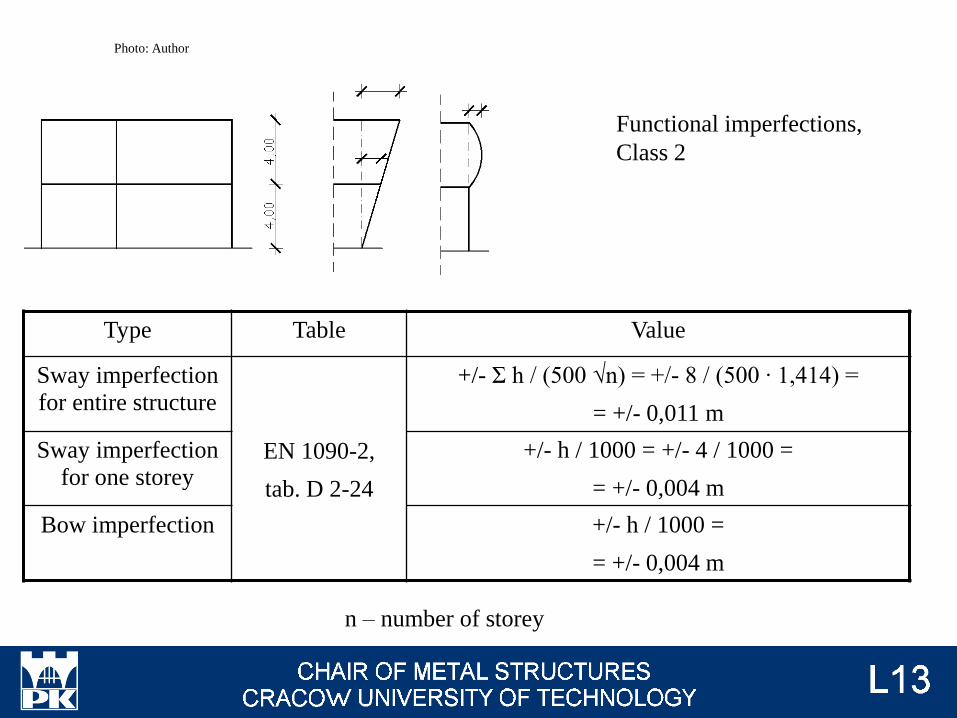
Functional imperfections,
Class 2
Type Table Value
Sway imperfection
for entire structure
EN 1090-2,
tab. D 2-24
+/- Σ h / (500 √n) = +/- 8 / (500 ∙ 1,414) =
= +/- 0,011 m
Sway imperfection
for one storey
+/- h / 1000 = +/- 4 / 1000 =
= +/- 0,004 m
Bow imperfection +/- h / 1000 =
= +/- 0,004 m
n – number of storey
Photo: Author

Sway imperfection - design
F = F0 ah am
F0 = 1 / 200
ah = max{ 2 / 3 ; min[ (2 / √h) ; 1,0]}
h – heigh of structure [m]
The maximum possible value of ah = 1,0
am = √[ 0,5 (1 + 1 / m)]
m - number of columns
The maximum possible value of am → 1,0
The maximum possible value of Fmax = 1 / 200
h
Photo: Author
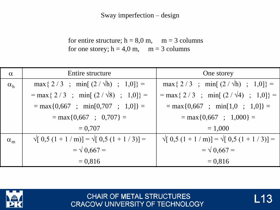
Sway imperfection – design
for entire structure; h = 8,0 m, m = 3 columns
for one storey; h = 4,0 m, m = 3 columns
a Entire structure One storey
ah max{ 2 / 3 ; min[ (2 / √h) ; 1,0]} =
= max{ 2 / 3 ; min[ (2 / √8) ; 1,0]} =
= max{0,667 ; min[0,707 ; 1,0]} =
= max{0,667 ; 0,707} =
= 0,707
max{ 2 / 3 ; min[ (2 / √h) ; 1,0]} =
= max{ 2 / 3 ; min[ (2 / √4) ; 1,0]} =
= max{0,667 ; min[1,0 ; 1,0]} =
= max{0,667 ; 1,000} =
= 1,000
am √[ 0,5 (1 + 1 / m)] = √[ 0,5 (1 + 1 / 3)] =
= √ 0,667 =
= 0,816
√[ 0,5 (1 + 1 / m)] = √[ 0,5 (1 + 1 / 3)] =
= √ 0,667 =
= 0,816

Sway imperfection – design
for entire structure; h = 8,0 m, m = 3 columns
for one storey; h = 4,0 m, m = 3 columns
Number of
storeys
Value
For analysed structure The maximum possible value
Entire structure +/- h F0 ah am =
= +/- 8 ∙ 0,707 ∙ 0,816 / 200 =
+ /- 0,023 m
+/- h Fmax = +/- 8 / 200 =
= +/- 0,040 m
One storey +/- h F0 ah am =
= +/- 4 ∙ 1,000 ∙ 0,816 / 200 =
+ /- 0,016 m
+/- h Fmax = +/- 4 / 200 =
= +/- 0,020 m

Bow imperfection - designBuckling curve Elastic analysis Plastic annalysis
a0 l / 350 l / 300
a l / 300 l / 250
b l / 250 l / 200
c l / 200 l / 150
d l / 150 l / 100
Columns HEB 300, S235, buckling about axis y, elastic
analysis → EN 1993-1-1 tab 6.2 → buckling curve b →
→ +/- h / 250 = +/- 4 / 250 = +/- 0,016 m
The maximum possible value +/- h / 100 = +/- 0,040 m
h
Photo: Author
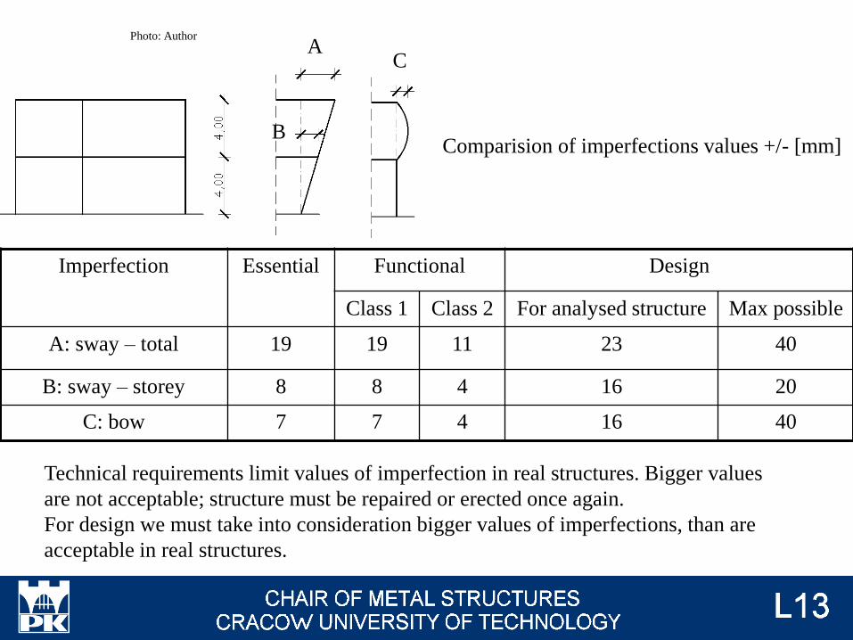
Comparision of imperfections values +/- [mm]
Imperfection Essential Functional Design
Class 1 Class 2 For analysed structure Max possible
A: sway – total 19 19 11 23 40
B: sway – storey 8 8 4 16 20
C: bow 7 7 4 16 40
Technical requirements limit values of imperfection in real structures. Bigger values
are not acceptable; structure must be repaired or erected once again.
For design we must take into consideration bigger values of imperfections, than are
acceptable in real structures.
Photo: Author
AC
B
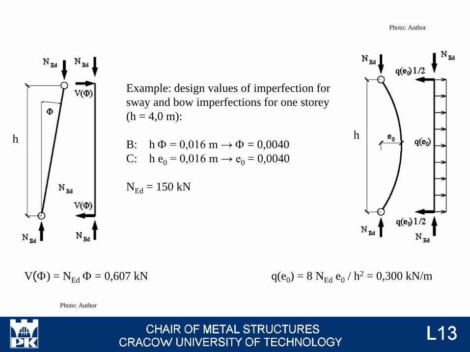
V(F) = NEd F = 0,607 kN
Example: design values of imperfection for
sway and bow imperfections for one storey
(h = 4,0 m):
B: h F = 0,016 m → F = 0,0040
C: h e0 = 0,016 m → e0 = 0,0040
NEd = 150 kN
q(e0) = 8 NEd e0 / h2 = 0,300 kN/m
h h
Photo: Author
Photo: Author

Multistorey frame - sway
imperfections
Level i
Level i-1
Level i+1 F i+1
h i
h i-1
F i
F i-1
h i+1Ni+1
Ni
Ni-1
Vi+1 - Vi+2
Vi - Vi+1
Vi-1 - Vi
Vi-2 - Vi-1
Photo: Author
Equivalent loads should be
applied in accordance with the
modes of instability.
Global = sway

Multistorey frame - bow
imperfections
Level i
Level i-1
Level i+1
e i+1
h i
h i-1
e i
e i-1
h i+1 Ni+1
Ni
Ni-1
(qi+1 hi+1 - qi+2 hi+2)/2
q i+1
q i
q i-1
(-qi hi + qi+1 hi+1)/2
(qi-1 hi-1 - qi hi)/2
(-qi-2 hi-2 + qi-1 hi-1)/2
Photo: Author
Local = bow

Types and examples of imperfections
Importance of exectuion class
Equivalent forces of imperfections
Examination issues

Stiffener - żeberko
Footing - stopa fundamentowa
Bracing – stężenie


![Karty Przedmiotów Subject Cards - wis.pwr.edu.plwis.pwr.edu.pl/fcp/6GBUKOQtTKlQhbx08SlkTVwRQX2o8DAoHNiwFE1... · PWN, Warszawa 1983 [2] Pikoń J.: Podstawy konstrukcji aparatury](https://static.fdocuments.us/doc/165x107/5c779d6909d3f291718c840c/karty-przedmiotow-subject-cards-wispwreduplwispwreduplfcp6gbukoqttklqhbx08slktvwrqx2o8daohniwfe1.jpg)