
Metal Structures II Lecture V Crane supporting …footbridge.pl/stud/z/se2/lec205.pdf · or...
139
Metal Structures II Lecture V Crane supporting structures Beams, columns, bracings
Transcript of Metal Structures II Lecture V Crane supporting …footbridge.pl/stud/z/se2/lec205.pdf · or...
Metal Structures II
Lecture V
Crane supporting structures
Beams, columns, bracings

Contents
Structure of lectures → #t / 3
Fatigue resistance → #t / 4
Deformations → #t / 26
Connections → #t / 38
Columns → #t / 42
Example 1 → #t / 78
Example 2 → #t / 102
Bracings → #t / 134
Examination issues → #t / 137

Loads → Lecture #3
Beams: geometry of cross-section, resistance, instability prevention, local
effects, transverse stiffeners bumpers → Lecture #4
Beams: fatigue resistance, deformations; Columns: geometry of cross-section,
resistance, instability, deformations; Bracings → Lecture #5
Parts important for IInd design project
Structure of lectures
→ #3 / 3
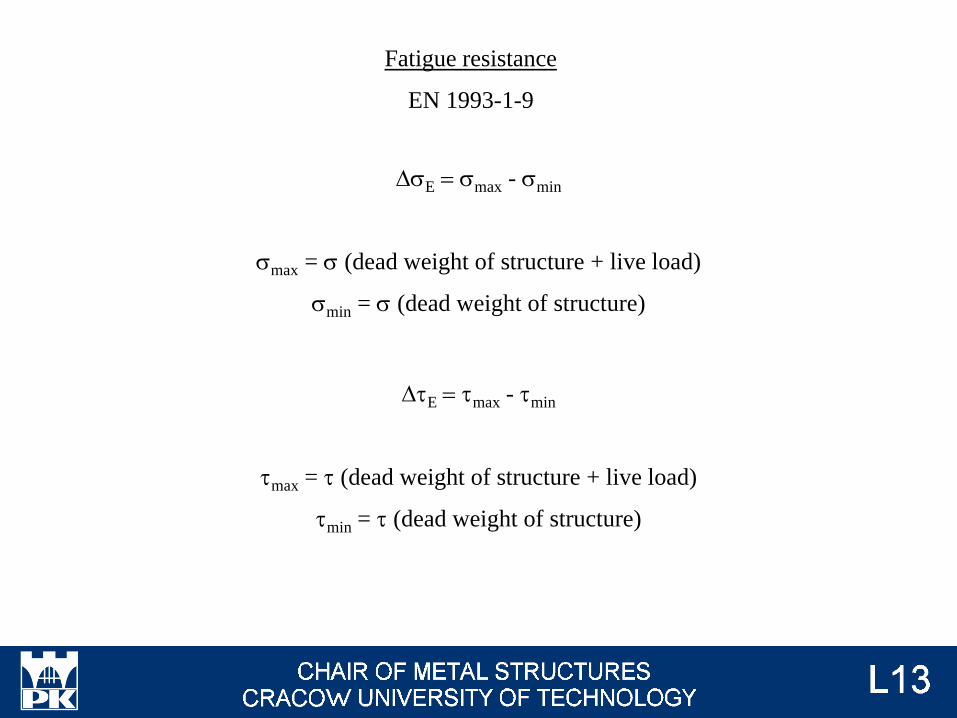
DsE = smax - smin
smax = s (dead weight of structure + live load)
smin = s (dead weight of structure)
DtE = tmax - tmin
tmax = t (dead weight of structure + live load)
tmin = t (dead weight of structure)
Fatigue resistance
EN 1993-1-9

gFf DsE / (sR / gMf) ≤ 1,0
gFf DtE / (tR / gMf) ≤ 1,0
Checking of fatugue resistance will be presented on lecture #5, at now only
calculation of load is presented.
Fatigue loads
EN 1991-1-9 (8.2)
→ #3 / 67
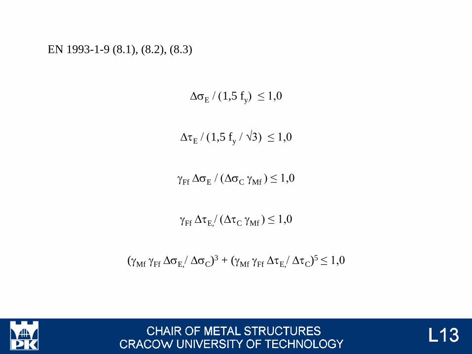
DsE / (1,5 fy) ≤ 1,0
DtE / (1,5 fy / √3) ≤ 1,0
gFf DsE / (DsC gMf ) ≤ 1,0
gFf DtE,/ (DtC gMf ) ≤ 1,0
(gMf gFf DsE,/ DsC)3 + (gMf gFf DtE,/ DtC)5 ≤ 1,0
EN 1993-1-9 (8.1), (8.2), (8.3)
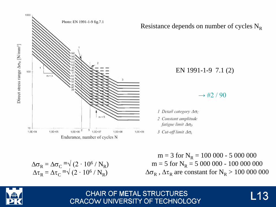
DsR = DsCm√ (2 ∙ 106 / NR)
DtR = DtCm√ (2 ∙ 106 / NR)
Resistance depends on number of cycles NR
m = 3 for NR = 100 000 - 5 000 000
m = 5 for NR = 5 000 000 - 100 000 000
DsR , DtR are constant for NR > 100 000 000
EN 1991-1-9 7.1 (2)
Photo: EN 1991-1-9 fig.7.1
→ #2 / 90
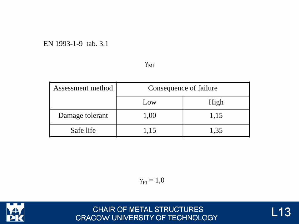
gMf
gFf = 1,0
EN 1993-1-9 tab. 3.1
Assessment method Consequence of failure
Low High
Damage tolerant 1,00 1,15
Safe life 1,15 1,35

EN 1993-1-9 3(7)
Damage tolerant method
• selecting details, materials and stress level so that in the event of the formation of
cracks a low rate of crack propagation and a long critical crack length would result
• provision of multiple load path
• provision of crack-arresting details
• provision of readily inspectable details during regular inspections
Safe-life method
• selecting details and stress levels resulting in a fatigue life sufficient to achieve the b-
values to be at least equal to those required for ultimate limit state verifications at the end
of the design service life
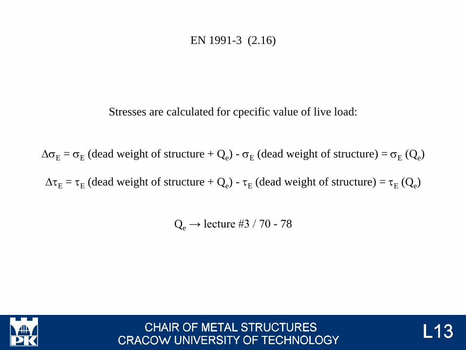
Stresses are calculated for cpecific value of live load:
DsE = sE (dead weight of structure + Qe) - sE (dead weight of structure) = sE (Qe)
DtE = tE (dead weight of structure + Qe) - tE (dead weight of structure) = tE (Qe)
Qe → lecture #3 / 70 - 78
EN 1991-3 (2.16)

EN 1991-3 (2.16), (2.19)
→ #3 / 70
DsE = DsE (Qe)
DtE = DtE (Qe)
Qe = Qmax,i jfat li
Qmax,i → #3 / 35, 36
jfat = max ( jfat,1 ; jfat,2)
jfat,1 = (1 + j1) / 2
jfat,2 = (1 + j2) / 2
li → #3 / 68

li damage equivalent factor
Simplified approach
EN 1991-3
Semi-accurate approach
EN 1993-1, EN 13001-1
Accurate approach
EN 1993-1, EN 13001-1
kQ - EN 13001-1
SX EN 1993-1 app. B EN 1993-1 tab. 2.11
li EN 1993-1 tab. 2.12 EN 1993-1 (2.17), (2.18)
EN 1991-3 2.12.1
kQ - load spectrum factor
SX - crane class
→ #3 / 71
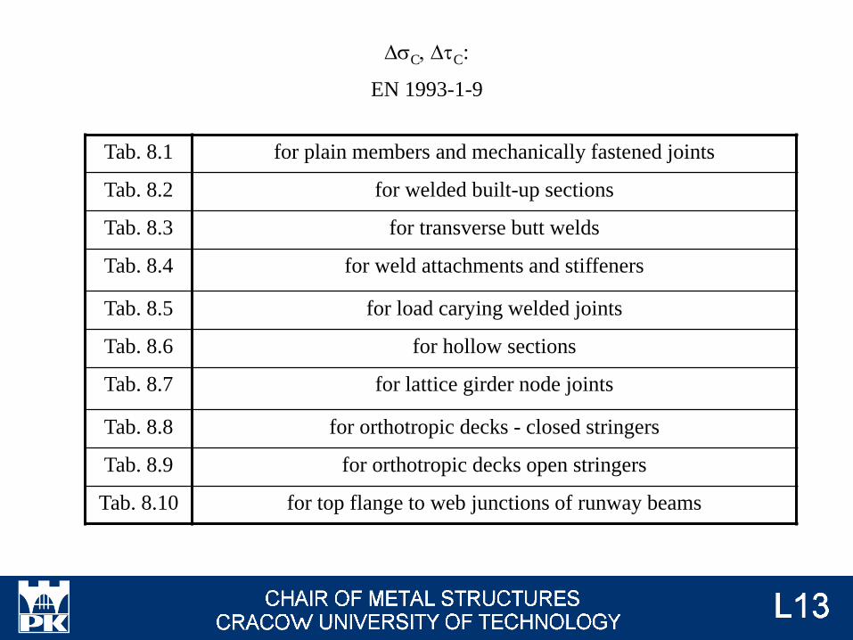
Tab. 8.1 for plain members and mechanically fastened joints
Tab. 8.2 for welded built-up sections
Tab. 8.3 for transverse butt welds
Tab. 8.4 for weld attachments and stiffeners
Tab. 8.5 for load carying welded joints
Tab. 8.6 for hollow sections
Tab. 8.7 for lattice girder node joints
Tab. 8.8 for orthotropic decks - closed stringers
Tab. 8.9 for orthotropic decks open stringers
Tab. 8.10 for top flange to web junctions of runway beams
DsC, DtC:
EN 1993-1-9
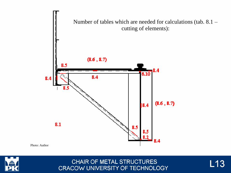
Number of tables which are needed for calculations (tab. 8.1 –
cutting of elements):
Photo: Author
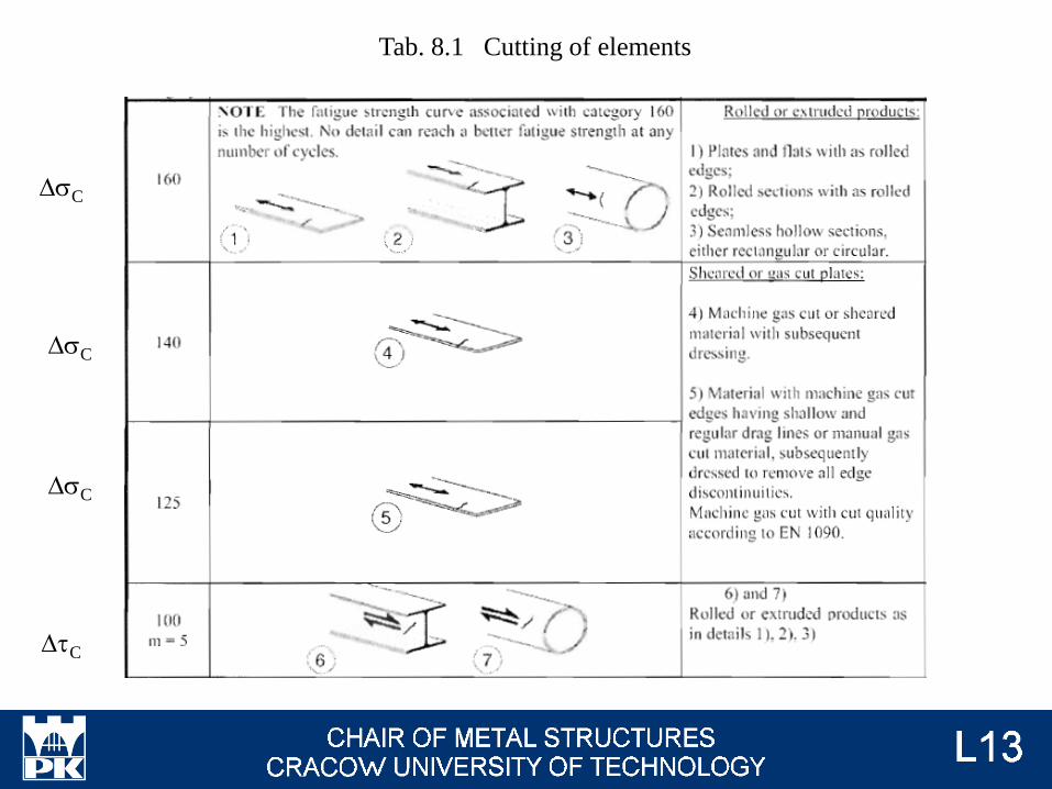
Tab. 8.1 Cutting of elements
DsC
DsC
DsC
DtC
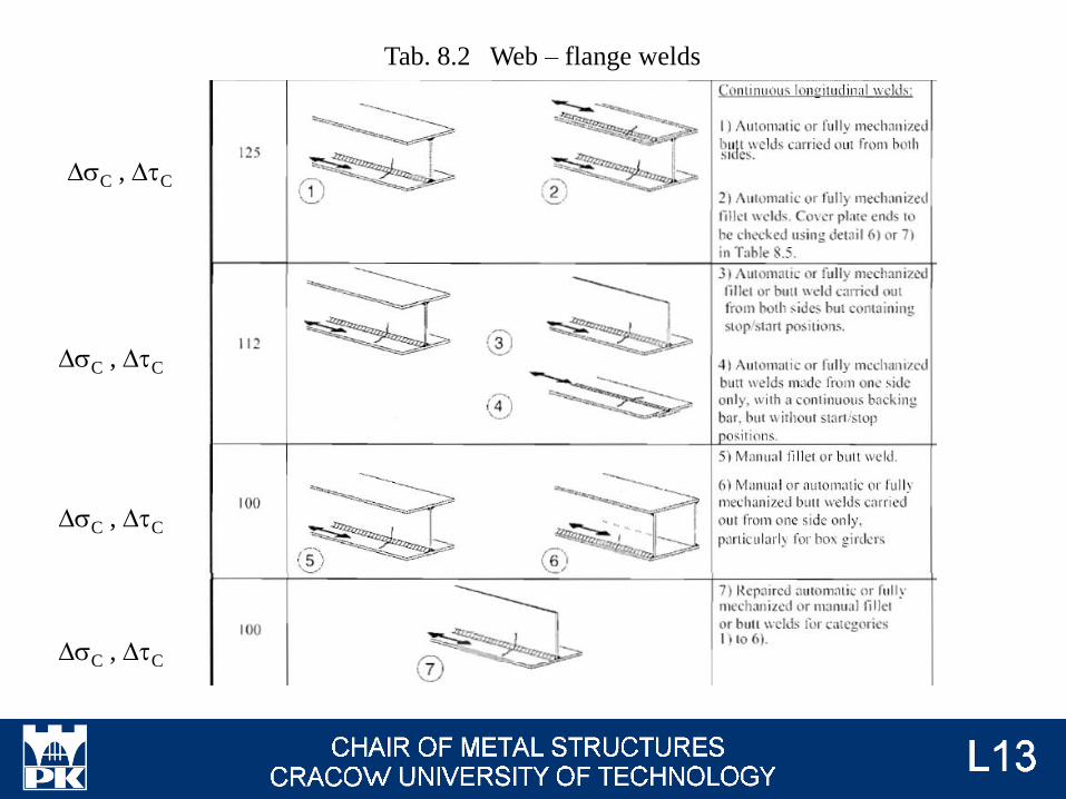
Tab. 8.2 Web – flange welds
DsC , DtC
DsC , DtC
DsC , DtC
DsC , DtC
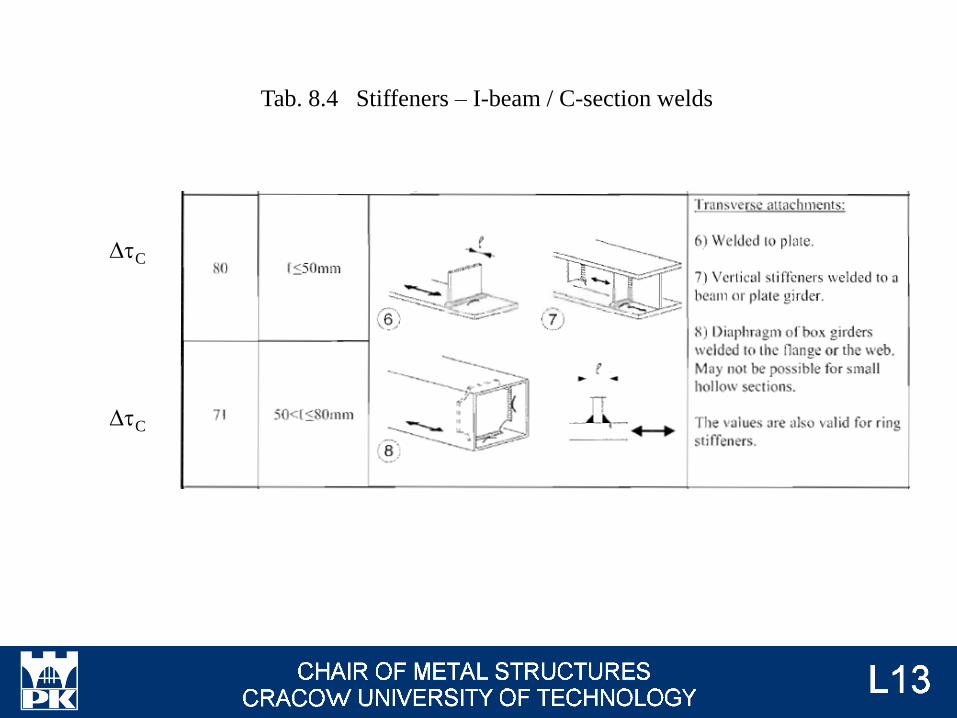
Tab. 8.4 Stiffeners – I-beam / C-section welds
DtC
DtC
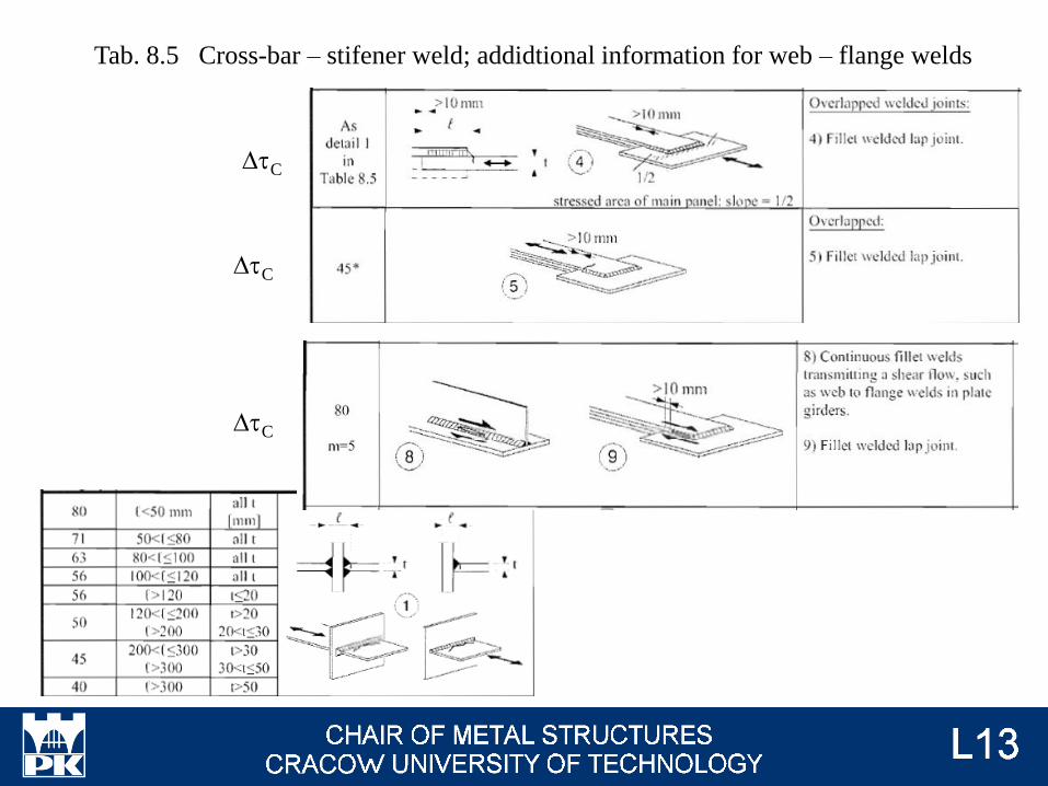
Tab. 8.5 Cross-bar – stifener weld; addidtional information for web – flange welds
DtC
DtC
DtC

Tab. 8.6 Hollow section
Tab. 8.7 Lattice girder
For lattice surge girder and
truss beam

Tab. 8.10 Web – flange welds for top flange
DsC , DtC
DsC , DtC
DsC , DtC
DsC , DtC
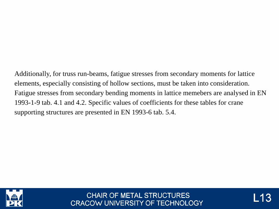
Additionally, for truss run-beams, fatigue stresses from secondary moments for lattice
elements, especially consisting of hollow sections, must be taken into consideration.
Fatigue stresses from secondary bending moments in lattice memebers are analysed in EN
1993-1-9 tab. 4.1 and 4.2. Specific values of coefficients for these tables for crane
supporting structures are presented in EN 1993-6 tab. 5.4.

EN 1993-6 8.2
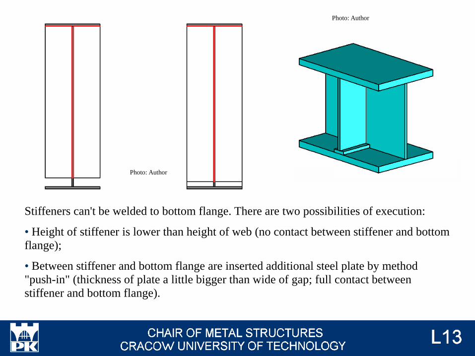
Stiffeners can't be welded to bottom flange. There are two possibilities of execution:
• Height of stiffener is lower than height of web (no contact between stiffener and bottom
flange);
• Between stiffener and bottom flange are inserted additional steel plate by method
"push-in" (thickness of plate a little bigger than wide of gap; full contact between
stiffener and bottom flange).
Photo: Author
Photo: Author
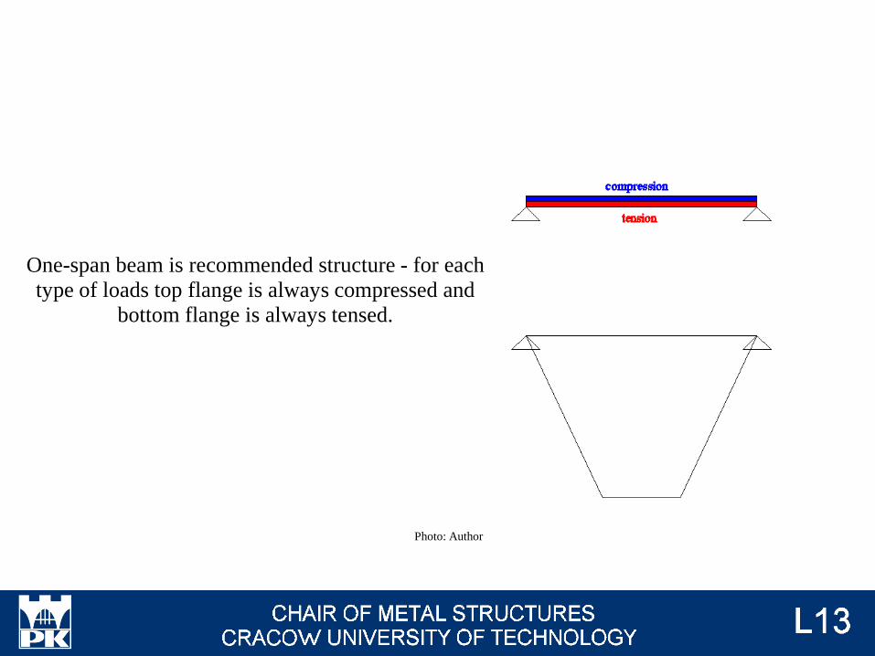
One-span beam is recommended structure - for each
type of loads top flange is always compressed and
bottom flange is always tensed.
Photo: Author
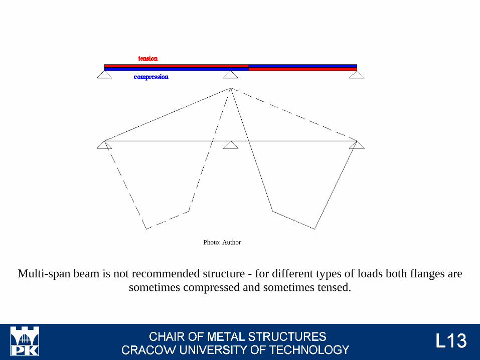
Multi-span beam is not recommended structure - for different types of loads both flanges are
sometimes compressed and sometimes tensed.
Photo: Author
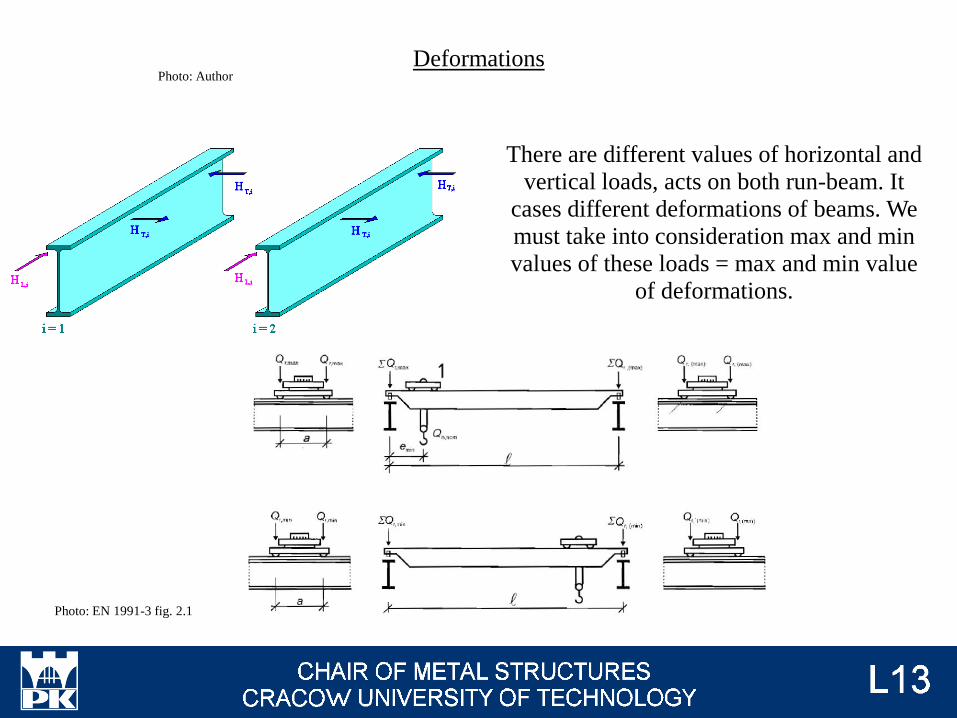
Deformations
There are different values of horizontal and
vertical loads, acts on both run-beam. It
cases different deformations of beams. We
must take into consideration max and min
values of these loads = max and min value
of deformations.
Photo: Author
Photo: EN 1991-3 fig. 2.1
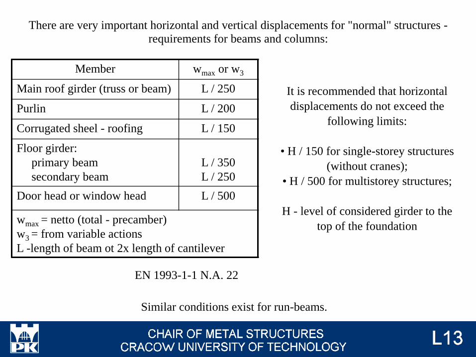
There are very important horizontal and vertical displacements for "normal" structures -
requirements for beams and columns:
Similar conditions exist for run-beams.
Member wmax or w3
Main roof girder (truss or beam) L / 250
Purlin L / 200
Corrugated sheel - roofing L / 150
Floor girder:
primary beam
secondary beam
L / 350
L / 250
Door head or window head L / 500
wmax = netto (total - precamber)
w3 = from variable actions
L -length of beam ot 2x length of cantilever
EN 1993-1-1 N.A. 22
It is recommended that horizontal
displacements do not exceed the
following limits:
• H / 150 for single-storey structures
(without cranes);
• H / 500 for multistorey structures;
H - level of considered girder to the
top of the foundation

Additionally, there must be analysed relative deformations of two run-beams:
Photo: Author

dz ≤ min( L / 600 ; 25 mm)
dpay ≤ L / 500
EN 1993-6 tab. 7.1
Vertical deformation, crane:
Vertical deformation, monorail hoist block:
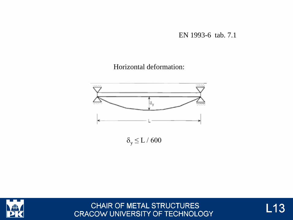
dy ≤ L / 600
EN 1993-6 tab. 7.1
Horizontal deformation:
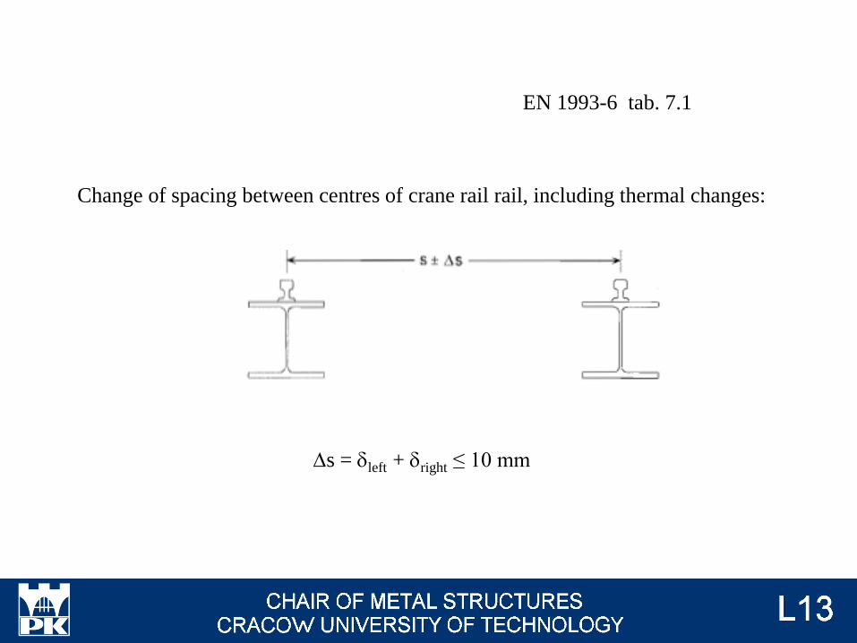
Ds = dleft + dright ≤ 10 mm
EN 1993-6 tab. 7.1
Change of spacing between centres of crane rail rail, including thermal changes:

EN 1993-6 tab. 7.1
Horizontal deflections and deviations of crane runways are considered together in crane
design. Acceptable deflections and tolerances demepn on the details and clearances in
guidance means. Provided that the clearance c between the crane wheel flanges and the
crane rail (or between the alternative guidance means and the crane beam) is also sufficent
to accomodate the necessary tolerance, larger deflection limits can be specified for each
project if agreed with the crane supplier and the client.

j4 = 1
provided that the tolerances for rail tracks as specified in EN 1993-6 are observed
othervise
→ EN 13001-2
j4 - dynamic effects induced when the crane is travelling;
EN 1991-3 tab. 2.4
↓
→ #3 / 31
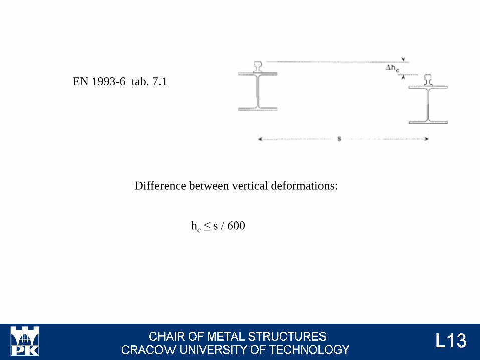
hc ≤ s / 600
EN 1993-6 tab. 7.1
Difference between vertical deformations:
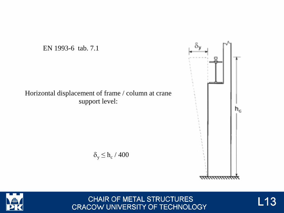
dy ≤ hc / 400
EN 1993-6 tab. 7.1
Horizontal displacement of frame / column at crane
support level:
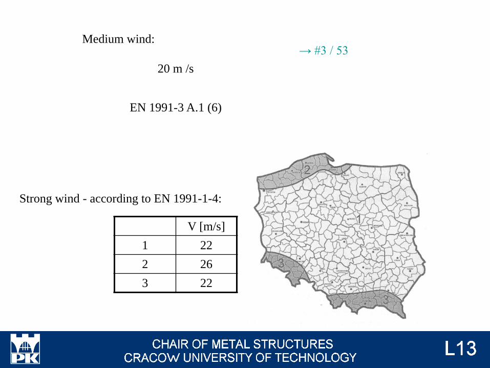
V [m/s]
1 22
2 26
3 22
20 m /s
EN 1991-3 A.1 (6)
Strong wind - according to EN 1991-1-4:
Medium wind:→ #3 / 53

dy ≤ L / 600
dy ≤ L / 400
EN 1993-6 tab. 7.1
Difference between horizontal
displacements of adjaced frames / columns)
• out-off-service wind load (outdoor crane only):
• indoor crane (max wind load);
• outdoor crane (in-service wind load);
• combination: wind (max or in-service, respectively) + lateral
crane forces;

Connections
Surge connectors attaching the top flange of a runway beam to the supporting structure
should be capable of accommodating the rotation movements and vertical movements;
should take into account the possible need for lateral and vertical adjustment of the runway
beams.
Photo: EN 1993-6 fig. 8.1

Photo: EN 1993-6 fig 8.2
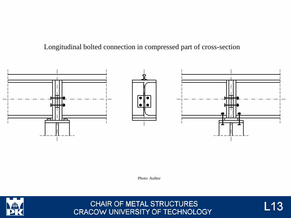
Photo: Author
Longitudinal bolted connection in compressed part of cross-section

Rail fixings
Photo: EN 1993-6 fig. 8.3
Joint of rails oblique and offset from the joint of beams

Columns
Photo: konar.eu
Photo: stabud.eu
Photo: zksgrzelak.eu
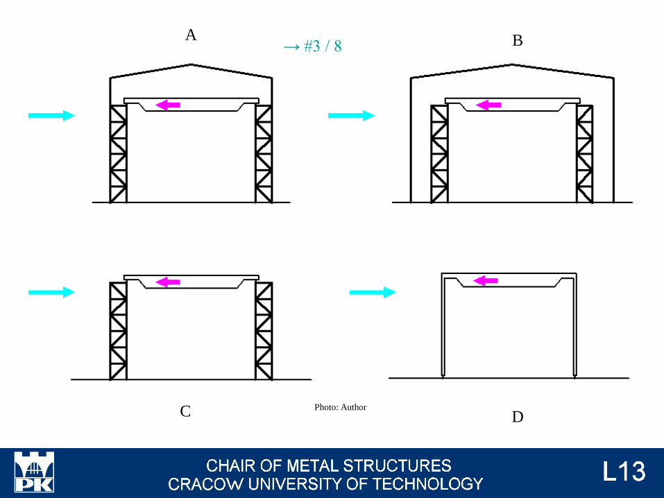
A B
C DPhoto: Author
→ #3 / 8
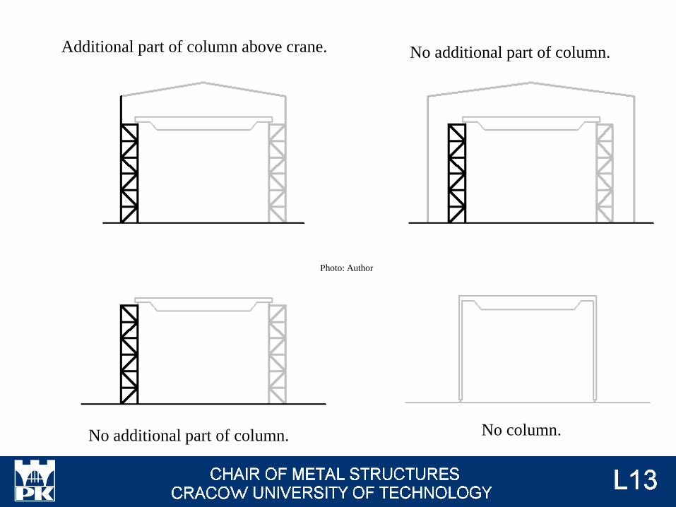
Additional part of column above crane. No additional part of column.
No additional part of column. No column.
Photo: Author
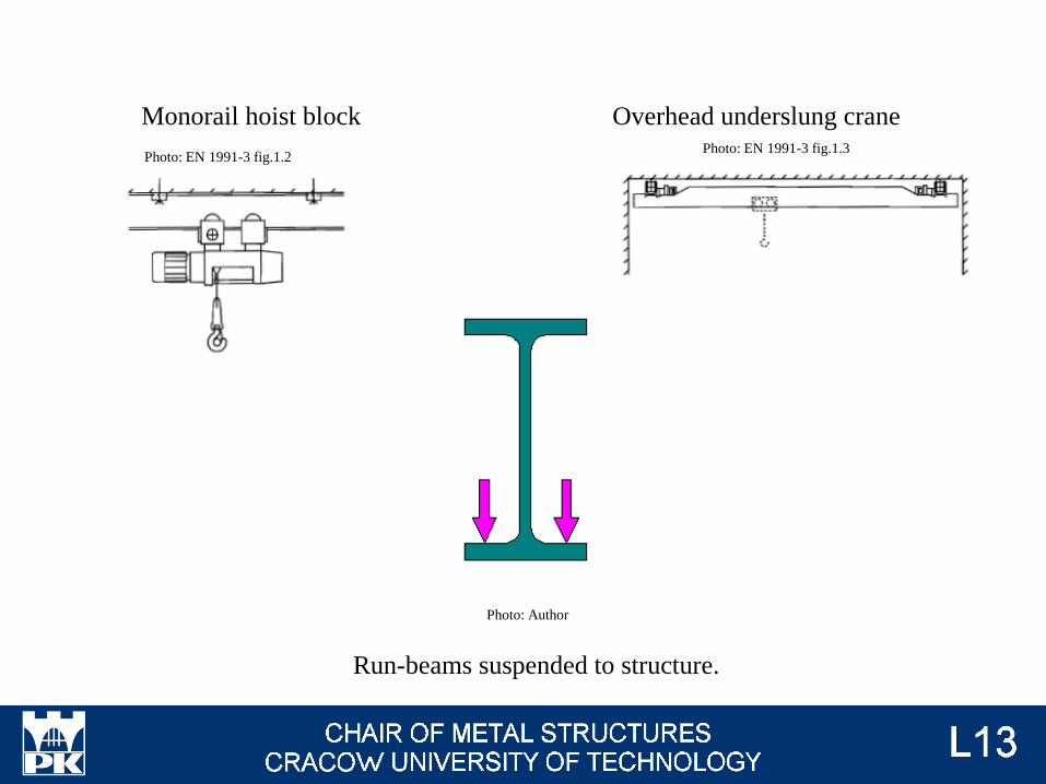
Monorail hoist block Overhead underslung crane
Run-beams suspended to structure.
Photo: Author
Photo: EN 1991-3 fig.1.2 Photo: EN 1991-3 fig.1.3
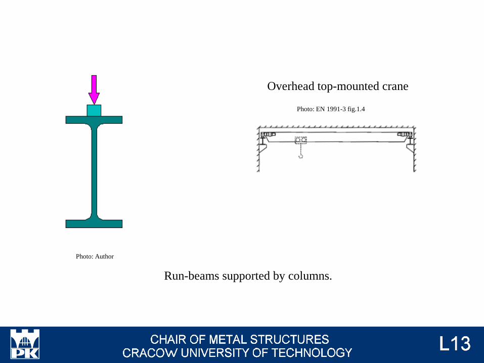
Run-beams supported by columns.
Overhead top-mounted crane
Photo: Author
Photo: EN 1991-3 fig.1.4
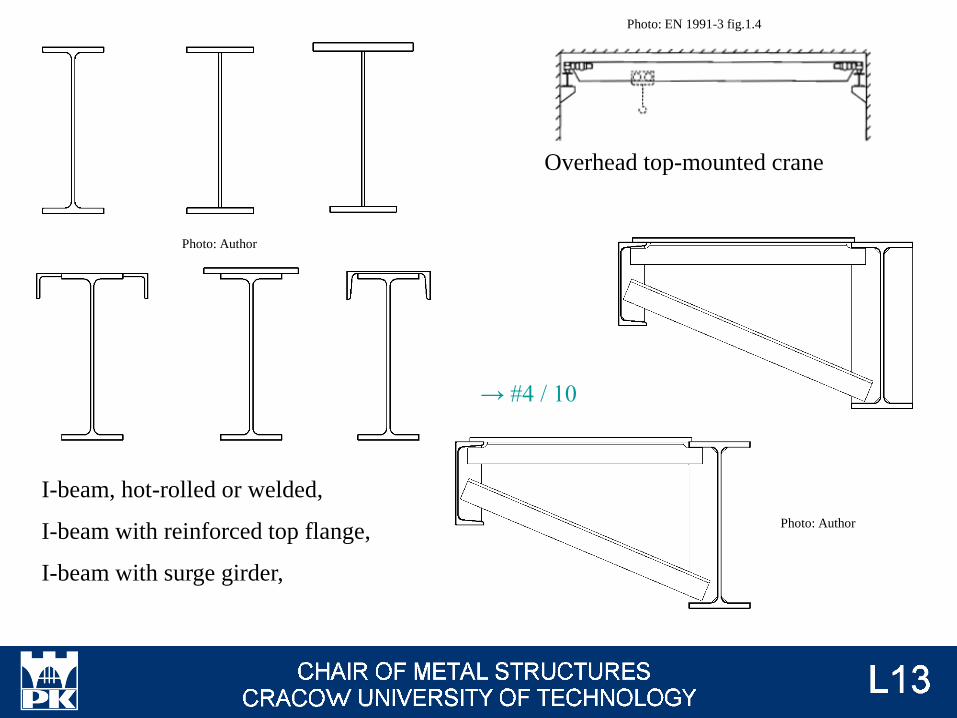
Overhead top-mounted crane
I-beam, hot-rolled or welded,
I-beam with reinforced top flange,
I-beam with surge girder,
Photo: Author
Photo: Author
Photo: EN 1991-3 fig.1.4
→ #4 / 10

Photo: crscranesystems.com
Photo: abuscranes.pl
Monorail hoist block and underslung crane - the most often solution is suspension run-
beams to structure of hall or additional portal frame.
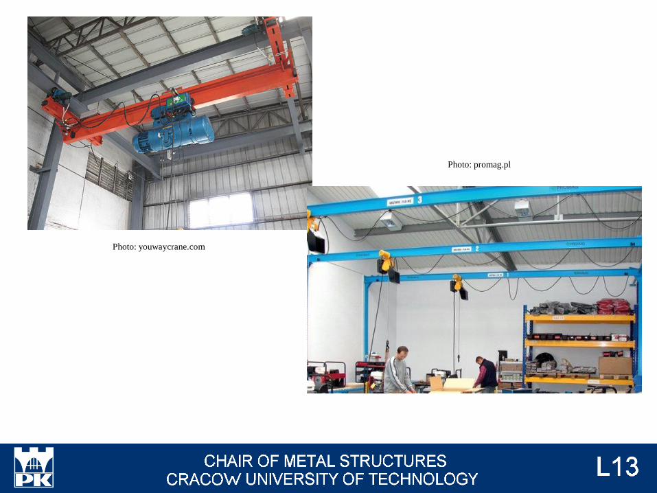
Photo: youwaycrane.com
Photo: promag.pl

Top-mounted crane
Hot-rolled I-beam
Welded I-beam (plates)
Hot-rolled I-beam
Welded I-beam (plates)
On cantilever
Different cross-section for boht part of
column
Welded I-beam (C-sections, I-
beams, plates)
Laced members
Battened members
Welded I-beam (C-sections, I-beams,
plates)
Laced members
Battened members
Different cross-section for boht part of
column
Photo: Author

Cantilever, change of cross-section.
Photo: konar.eu

Cantilever, no change of cross-section.
Photo: udhavind.com
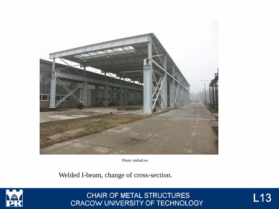
Welded I-beam, change of cross-section.
Photo: stabud.eu
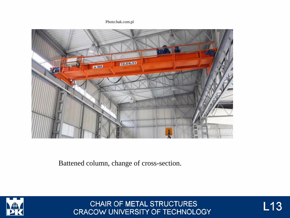
Battened column, change of cross-section.
Photo:hak.com.pl

Laced column.
Photo: zksgrzelak.eu
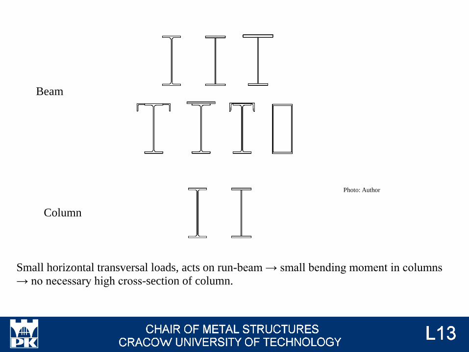
Beam
Column
Small horizontal transversal loads, acts on run-beam → small bending moment in columns
→ no necessary high cross-section of column.
Photo: Author

Beam
Column
Big horizontal transversal loads, acts on run-beam → big bending moment in columns →
there is necessary high cross-section of column.
or battened or laced columnPhoto: Author

Change of column cross-section → problem with calculations of stability. There is no
information in Eurocode for this case. There is proposal of calculations according to
"Tablice do projektowania konstrukcji metalowych", W. Bogucki, M. Żyburtowicz, Arkady,
Warszawa 1984
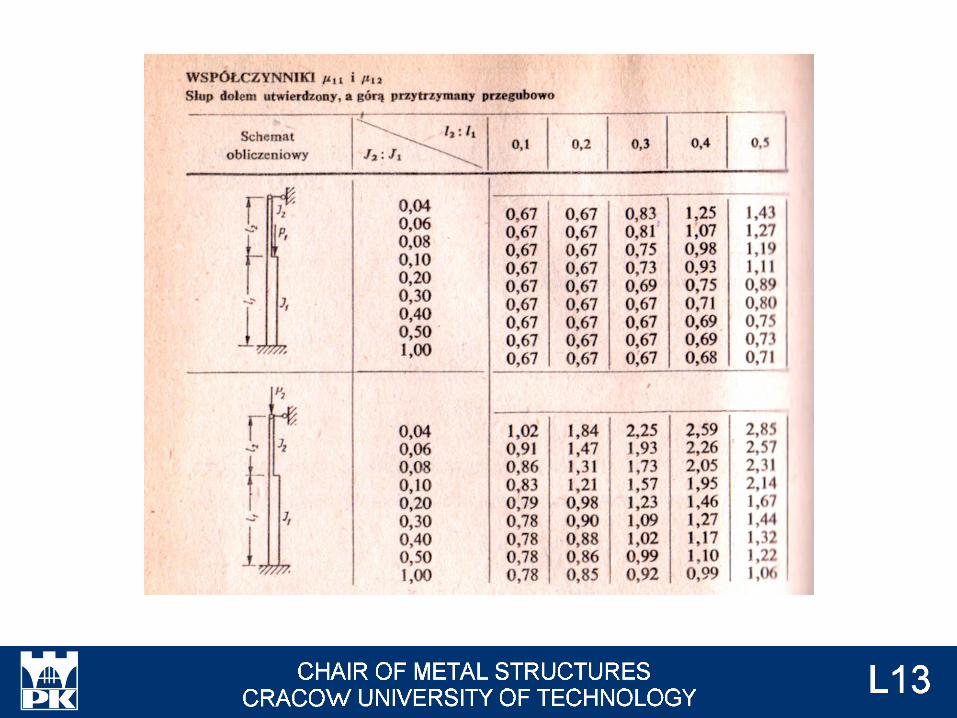

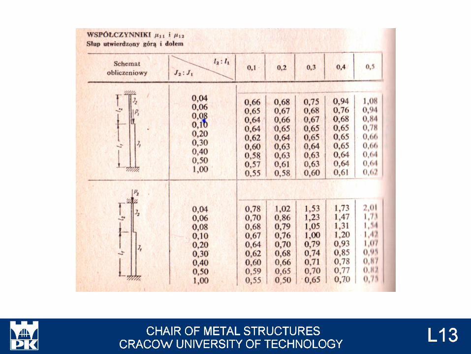
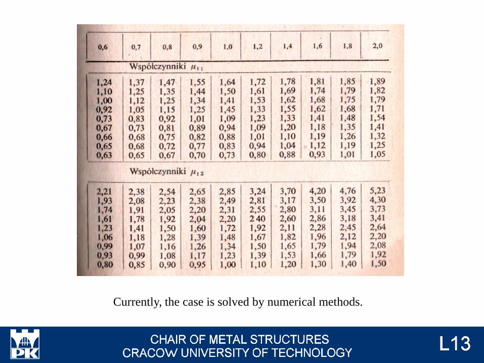
Currently, the case is solved by numerical methods.

There is special way of calculations for laced columns and battened columns according to
Eurocode.
Photo: EN 1993-1-1 fig 6.7
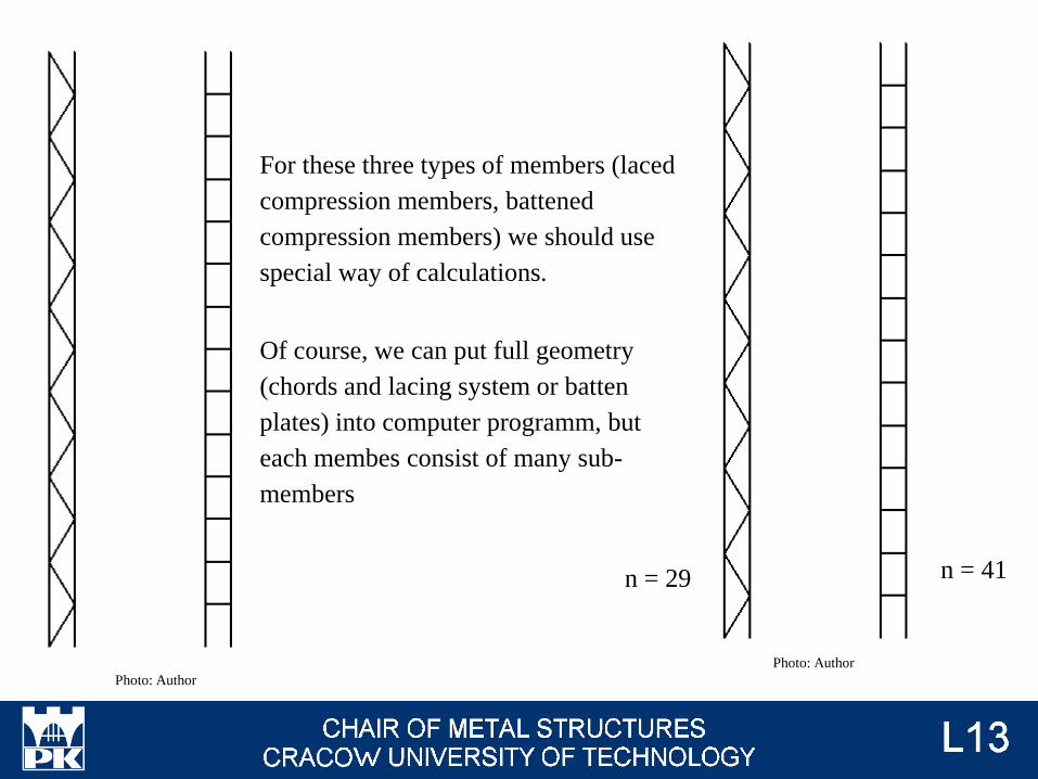
n = 29 n = 41
For these three types of members (laced
compression members, battened
compression members) we should use
special way of calculations.
Of course, we can put full geometry
(chords and lacing system or batten
plates) into computer programm, but
each membes consist of many sub-
members
Photo: Author
Photo: Author
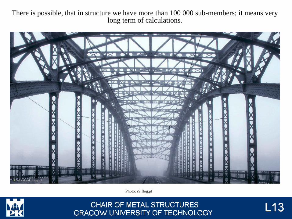
There is possible, that in structure we have more than 100 000 sub-members; it means very long term of calculations.
Photo: s9.flog.pl
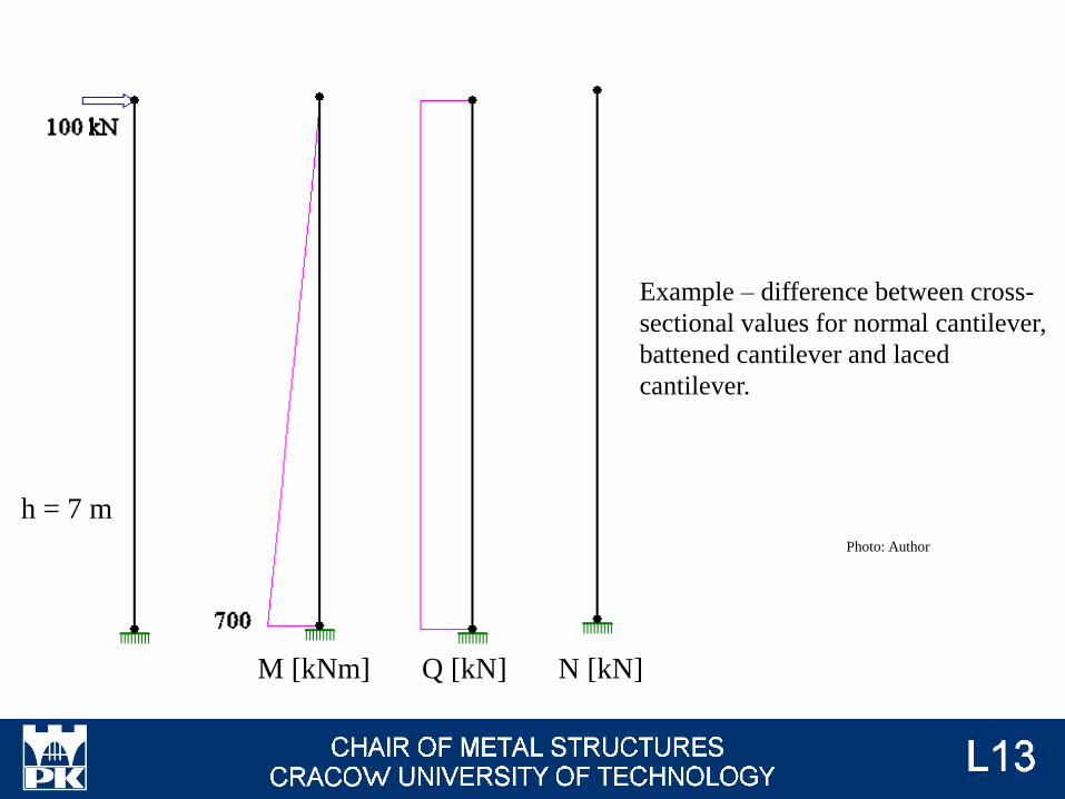
h = 7 m
Example – difference between cross-
sectional values for normal cantilever,
battened cantilever and laced
cantilever.
Photo: Author
M [kNm] Q [kN] N [kN]

h0 = 30 cm
Photo: Author
M [kNm] Q [kN] N [kN]

h0 = 100 cm Photo: Author
M [kNm] Q [kN] N [kN]
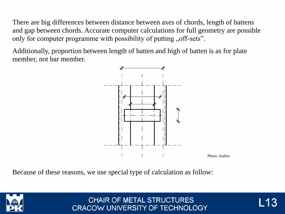
There are big differences between distance between axes of chords, length of battens
and gap between chords. Accurate computer calculations for full geometry are possible
only for computer programme with possibility of putting „off-sets”.
Additionally, proportion between length of batten and high of batten is as for plate
member, not bar member.
Because of these reasons, we use special type of calculation as follow:
Photo: Author
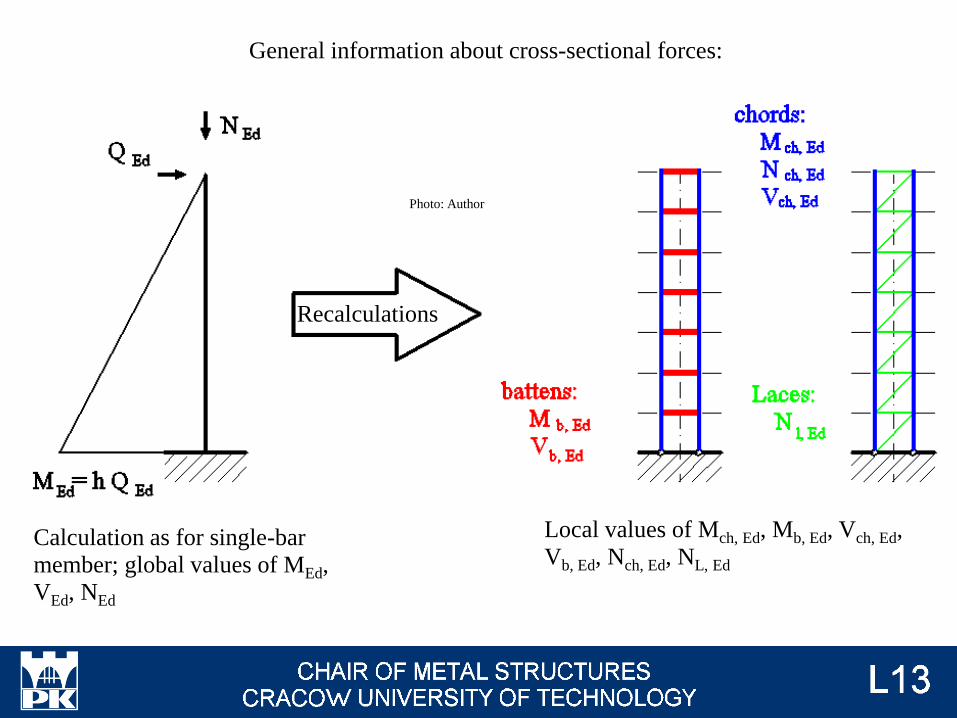
General information about cross-sectional forces:
Recalculations
Photo: Author
Calculation as for single-bar
member; global values of MEd,
VEd, NEd
Local values of Mch, Ed, Mb, Ed, Vch, Ed,
Vb, Ed, Nch, Ed, NL, Ed

Photo: Author
Variuos modes of instability must be taken into consideration:

SV L / 2 L L / [ 1 + Ad h03 / AV d3 ) ] min {
24 X / [1 + 2 Jch h0 / (n Jb a )] ;
2 p X }
Jeff 0,5 h02 Ach 0,5 h0
2 Ach + 2 meff Jch

L = n E Ad a h02 / d3
X = E Jch / a2
n = 4 n = 2
l = m L / i0
i0 = √ [ J1 / ( 2 Ach ) ]
J1 = 0,5 h02 Ach + 2 Jch
l meff
0
2 - l / 75
1,0
≥ 150
≤ 75
75 - 150
EN 1993-1-1 tab. 6.8
↑ EN 1993-1-1 fig 6.7, 6.9, (6.72), (6.73), (6.74)
n - number of battens planes
h0 - distance between centres of
gravity of chords
Xch - geometical characteristic of
one chord
Jb - moment of inertia for cross-
section of batten
J = 2 zs2 Ach + 2 Jch
Photo: Author

VEd = p MEdII / (n L)
h0 = 2 zs
For chord:
Vch, Ed = VEd / 2
Mch, Ed = a VEd / 4
For batten:
Vb, Ed = VEd a / (2 h0)
Mb, Ed = a VEd / 2
EN 1993-1-1 fig 6.11
Nch, Ed = NEd / 2 + 2 MEdII zs Ach / (2 Jeff)
MEd II = NEd e0 / [1 - (NEd / Ncr) - (NEd / SV)]
e0 = L / 500
Ncr = p2 E Jeff, / (m L)2
EN 1993-1-1 6.4.1

For laces:
VEd = p MEd / (n L)
Nl, Ed = VEd / cos a = p MEd / (n L cos a)
Photo: Author
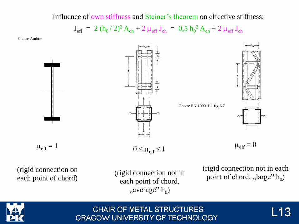
Influence of own stiffness and Steiner’s theorem on effective stiffness:
Jeff = 2 (h0 / 2)2 Ach + 2 meff Jch = 0,5 h02 Ach + 2 meff Jch
meff = 1
(rigid connection on
each point of chord)
meff = 0
(rigid connection not in each
point of chord, „large” h0)
0 ≤ meff ≤ 1
(rigid connection not in
each point of chord,
„average” h0)
Photo: Author
Photo: EN 1993-1-1 fig 6.7

There is inconsequence in Eurocode: according EN 1993-1-1 p.6.4.1.(1) - general
information - olny compressed members can be calculated acording to presented
procedure. On the other hand, in EN 1993-1-1 p.6.4.1.(6), global bending moment
is analysed. But there is no information, if resistance on global bending moment and
lateral buckling should be taken into consideration. For safety, these aspects should
be taken into account.

Example 1
300 kN
50 kN
Photo: Author
S 235
C 300
Ach = A (C 300) = 58,8 cm2
Jch, y = Jy (C 300) = 7 640 cm4
Jch, z = Jz1 (C 300) = 473 cm4
L = 7,000 m
h0 = 246 mm
a = 1,000 m
NEd = 300,000 kN
VEd = 50,000 kN
Mz, Ed, max = 50 ∙ 7 = 350,000 kNm
n = 2

Algorithm of analysis:
General calculations → #t / 80
Glogal behaviour of column → #t / 82
Local behaviour of one chord → #t / 92
Batten → #t / 99
Welds between battens and chords → #t / 101
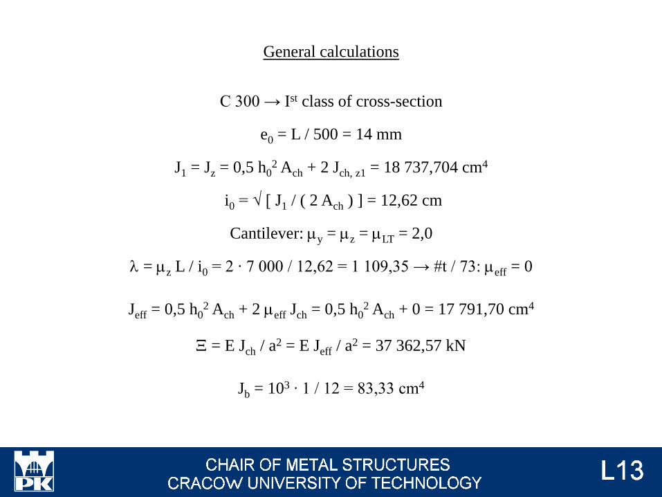
General calculations
C 300 → Ist class of cross-section
e0 = L / 500 = 14 mm
J1 = Jz = 0,5 h02 Ach + 2 Jch, z1 = 18 737,704 cm4
i0 = √ [ J1 / ( 2 Ach ) ] = 12,62 cm
Cantilever: my = mz = mLT = 2,0
l = mz L / i0 = 2 ∙ 7 000 / 12,62 = 1 109,35 → #t / 73: meff = 0
Jeff = 0,5 h02 Ach + 2 meff Jch = 0,5 h0
2 Ach + 0 = 17 791,70 cm4
X = E Jch / a2 = E Jeff / a2 = 37 362,57 kN
Jb = 103 ∙ 1 / 12 = 83,33 cm4
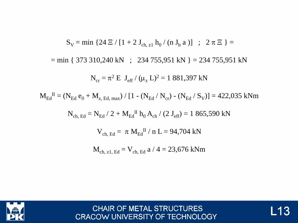
SV = min {24 X / [1 + 2 Jch, z1 h0 / (n Jb a )] ; 2 p X } =
= min { 373 310,240 kN ; 234 755,951 kN } = 234 755,951 kN
Ncr = p2 E Jeff / (mz L)2 = 1 881,397 kN
MEdII = (NEd e0 + Mz, Ed, max) / [1 - (NEd / Ncr) - (NEd / SV)] = 422,035 kNm
Nch, Ed = NEd / 2 + MEdII h0 Ach / (2 Jeff) = 1 865,590 kN
Vch, Ed = p MEdII / n L = 94,704 kN
Mch, z1, Ed = Vch, Ed a / 4 = 23,676 kNm
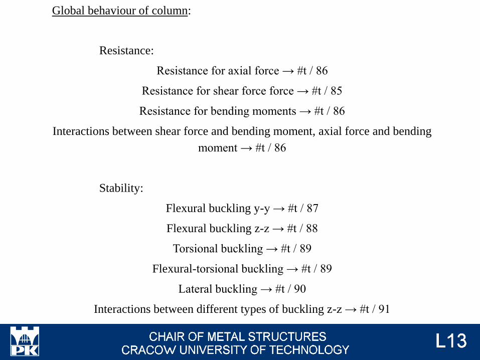
Global behaviour of column:
Resistance:
Resistance for axial force → #t / 86
Resistance for shear force force → #t / 85
Resistance for bending moments → #t / 86
Interactions between shear force and bending moment, axial force and bending
moment → #t / 86
Stability:
Flexural buckling y-y → #t / 87
Flexural buckling z-z → #t / 88
Torsional buckling → #t / 89
Flexural-torsional buckling → #t / 89
Lateral buckling → #t / 90
Interactions between different types of buckling z-z → #t / 91

Analysed cross-section consists of two completely separated parts. There in no information
about:
formulas for interaction between aial force and bending moment;
way of calculations of Jw for torsional and lateral buckling.
Cross-section is rough approximated by I-beam. With of flanges is equal depth of C-section.
Area of flange is equal area of C-section. Flanges centres of gravity are at the same points as
centres of grawity for C-sections. Thickness of web tends to 0. Resistance for shear force
will be calculated for four flanges of C-section.
Photo: Author

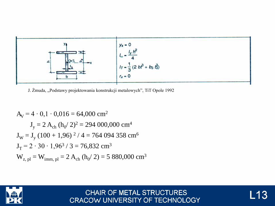
J. Żmuda, „Podstawy projektowania konstrukcji metalowych”, TiT Opole 1992
AV = 4 ∙ 0,1 ∙ 0,016 = 64,000 cm2
Jy = 2 Ach (h0/ 2)2 = 17 791,704 cm4
JW = Jy (24,6 + 1,96) 2 / 4 = 3 137 716 cm6
JT = 2 ∙ 30 ∙ 1,963 / 3 = 76,832 cm3
Wz, pl = Wimm, pl = 2 Ach (h0/ 2) = 1 446,480 cm3

NRd = 2 Ach fy / gM0 = 2 763,600 kN
VRd = AV fy / (gM0 √3) = 868,335 kN
Mz, Rd = Wimm, pl fy / gM0 = 339,923 kNm
VEd / VRd = 50,000 / 868,335 = 0,058 < 0,5 → no interaction between VEd and Mz, Ed

a = 2 b = max (5n ; 1,0)
n = NEd / Npl, Rd = 300,000 / 2 763,600 = 0,109 → b = 1,0
a = min [ 0,5 ; (A - 2 b tf) / A]
(A - 2 b tf) / A = (for approximation, thickness of web → 0) = 0,0
a = min [ 0,5 ; 0,0] = 0,0
min ( 0,25 Npl, Rd ; 0,5 hw tw fy / gM0 ) = (for approximation, thickness of web → 0) = 0 kN
NEd > 0 kN → interaction between NEd and Mz, Ed.
MN,z, Rd = min [Mz, Rd ; Mz, Rd (1 - n) / (1 - 0,5 a) ] =
= [339,923 kNm ; 339,923 kNm (1 - 0,109) / (1 - 0,5 ∙ 0,0)] = 302,871 kNm
Mz, Ed / MN, z, Rd = 1,156 WRONG

y- y (material axis) flexural buckling
NEd = 300,000 kN (→ #t / 78)
NRd = 2 763,600 kN (→ #t / 85)
Jy = 2 Jch, y = 15 280 cm4
Lcr = 2 L = 14,000 m
iy = √ (Jy / A) = √ (2 Jch, y / 2 Ach) = 11,40 cm
ly = 1,308
Buckling curve c → a = 0,49
Fy = 1,627
cy = 0,385
NEd / (cy NRd) = 0,262 < 1,000 ok
Photo: Author
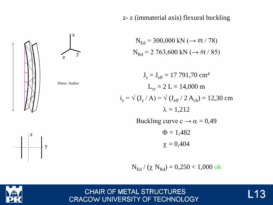
z- z (immaterial axis) flexural buckling
NEd = 300,000 kN (→ #t / 78)
NRd = 2 763,600 kN (→ #t / 85)
Jz = Jeff = 17 791,70 cm4
Lcr = 2 L = 14,000 m
iz = √ (Jz / A) = √ (Jeff / 2 Ach) = 12,30 cm
l = 1,212
Buckling curve c → a = 0,49
F = 1,482
c = 0,404
NEd / (c NRd) = 0,250 < 1,000 ok
Photo: Author

Torsional buckling Ncr, T = [p2 EJw / (mT l0T)2 + GJT] / is2
i0 = √ (iy2 + iz
2) = 16,86 cm
is = √ (i02 + zs
2) = 16,86 cm
Ncr, T = 217 397,756 kN
Flexural-torsional buckling Ncr, z-T = {Ncr, i + Ncr, T - √ [(Ncr, i + Ncr, T)2 - 4 Ncr, i Ncr, T x] } / (2 x)
m = min [√ (mz / mLT) ; √ (mLT / mz)] = 1,0
x = 1 - (m zs2 / is
2) = 1
Ncr, i = min (Ncr, y ; Ncr, z) = Ncr, y = 1 615,795 kN
Ncr, z-T = 2 216,683 kN
Critical forces for torsional buckling and flexural-torsional buckling is bigger than
critical force for flexural buckling → flexural buckling is the most dangerous; there is
no need to control other modes.

Lateral buckling Mcr = is √ (Ncr, i Ncr, T) = 319,082 kNm
lLT = √ (MN,z, Rd / Mcr) = 0,974
aLT = 0,76
FLT = [1 + aLT (lLT - 0,2) + lLT2] / 2 = 1,267
cLT = min{ 1 / [FLT + √ (FLT2 - lLT
2)] ; 1,0} = 0,481
cLT, mod = 0,592
cLT, mod MN, z, Rd = 179,315 kNm
Cmy = Cmy = 0, 9
CmLT = 0,6
kyy = 1,035
kyz = 0,653
kzy = 0,902
kzz = 1,089

NEd / ( cy NRk / gM1) + kyy (My, Ed + DMy, Ed ) / ( cLT M y, Rk / gM1) +
+ kyz ( Mz, Ed + DMz, Ed ) / (M z, Rk / gM1) ≤ 1,0
0,262 + 1,035 ∙ 1,952 = 2,282 > 1,0 WRONG
NEd / ( cz NRk / gM1) + kzy (My, Ed + DMy, Ed ) / ( cLT M y, Rk / gM1) +
+ kzz ( Mz, Ed + DMz, Ed ) / (M z, Rk / gM1) ≤ 1,0
0,250 + 0,902 ∙ 1,952 = 2,011 > WRONG

Local behaviour of column:
Resistance:
Resistance for axial force → #t / 95
Resistance for shear force → #t / 94
Resistance for bending moments → #t / 95
Interactions between shear force and bending moment, axial force and bending
moment → #t / 95
Stability:
Flexural buckling z1-z1 → #t / 96
Torsional buckling → #t / 97
Flexural-torsional buckling → #t / 97
Lateral buckling → #t / 98
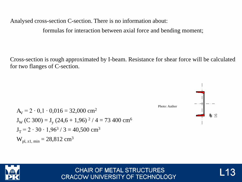
Analysed cross-section C-section. There is no information about:
formulas for interaction between axial force and bending moment;
Cross-section is rough approximated by I-beam. Resistance for shear force will be calculated
for two flanges of C-section.
Photo: Author
AV = 2 ∙ 0,1 ∙ 0,016 = 32,000 cm2
JW (C 300) = Jy (24,6 + 1,96) 2 / 4 = 73 400 cm6
JT = 2 ∙ 30 ∙ 1,963 / 3 = 40,500 cm3
Wpl, z1, min = 28,812 cm3
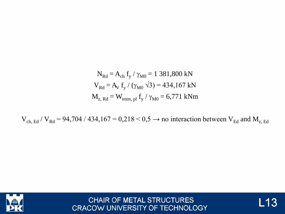
NRd = Ach fy / gM0 = 1 381,800 kN
VRd = AV fy / (gM0 √3) = 434,167 kN
Mz, Rd = Wimm, pl fy / gM0 = 6,771 kNm
Vch, Ed / VRd = 94,704 / 434,167 = 0,218 < 0,5 → no interaction between VEd and Mz, Ed

a = 2 b = max (5n ; 1,0)
n = NEd, ch / Npl, Rd = 1 865,590 / 1 381,800 = 1,350 → b = 6,751
a = min [ 0,5 ; (A - 2 b tf) / A]
(A - 2 b tf) / A = 0,456
a = min [ 0,5 ; 0,456] = 0,456
min ( 0,25 Npl, Rd ; 0,5 hw tw fy / gM0 ) = min (345,450 kN ; 352,500 kN) = 345,450 kN
NEd, ch > 345,450 kN → interaction between NEd and Mz, Ed.
MN,z, Rd = min [Mz, Rd ; Mz, Rd (1 - n) / (1 - 0,5 a) ] =
= [6,771 kNm ; 6,771 kNm (1 - 1,350) / (1 - 0,5 ∙ 0,456)] = lower than zero value; nonsense. It is result of NEd, ch > Npl, Rd
Mz, Ed / MN, z, Rd >> 1,0 WRONG
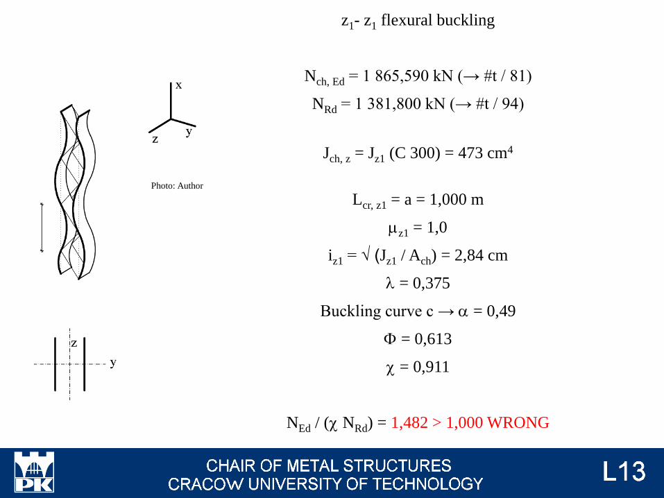
z1- z1 flexural buckling
Nch, Ed = 1 865,590 kN (→ #t / 81)
NRd = 1 381,800 kN (→ #t / 94)
Jch, z = Jz1 (C 300) = 473 cm4
Lcr, z1 = a = 1,000 m
mz1 = 1,0
iz1 = √ (Jz1 / Ach) = 2,84 cm
l = 0,375
Buckling curve c → a = 0,49
F = 0,613
c = 0,911
NEd / (c NRd) = 1,482 > 1,000 WRONG
Photo: Author

Torsional buckling Ncr, T = [p2 EJw / (mT l0T)2 + GJT] / is2
i0 = √ (iy2 + iz
2) = 12,05 cm
is = √ (i02 + zs
2) = 15,51 cm
Ncr, T = 141 009,672 kN
Flexural-torsional buckling Ncr, z-T = {Ncr, z1 + Ncr, T - √ [(Ncr, z1 + Ncr, T)2 - 4 Ncr, z1 Ncr, T x] }/(2 x)
m = min [√ (mz / mLT) ; √ (mLT / mz)] = 1,0
x = 1 - (m zs2 / is
2) = 0,954
Ncr, z1 = 9 336,646 kN
Ncr, z-T = 17 756,694 kN
Critical forces for torsional buckling and flexural-torsional buckling is bigger than
critical force for flexural buckling → flexural buckling is the most dangerous; there is
no need to control other modes.
Lateral buckling: bending moment acts about weak axis. Because of this, there is no laeral
buckling and no interaction between flexural and lateral buckling.
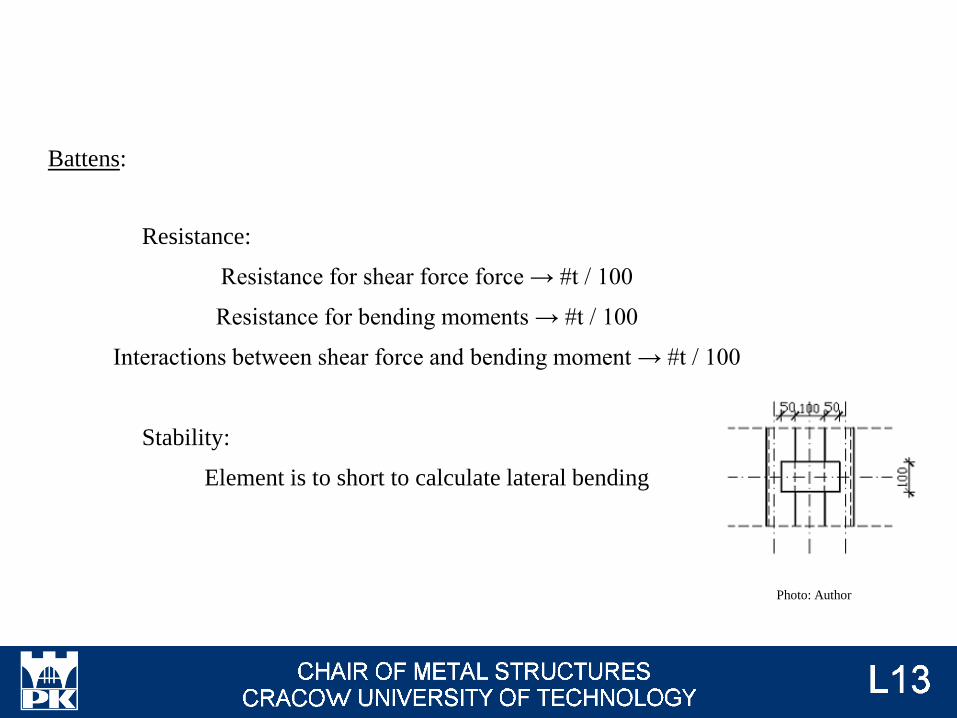
Battens:
Resistance:
Resistance for shear force force → #t / 100
Resistance for bending moments → #t / 100
Interactions between shear force and bending moment → #t / 100
Stability:
Element is to short to calculate lateral bending
Photo: Author

Nb,Ed = 0
Mb,Ed = Vch, Ed a / 2 = 47,352 kNm
Vb,Ed = Vch, Ed a / h0 = 384,975 kN
Cross section z-z: 2x rectangular 100 mm x 10 mm
Mch, Rd, z = 7,833 kNm
Vch, Rd = 271,354 kN
Calculations of resistances and interaction is made according to the
same way, as for other cross-section under shear force and bending
moment. But, at this example:
Vb,Ed / VRd > 1,0
Mb,Ed / MRd > 1,0
WRONGPhoto: Author
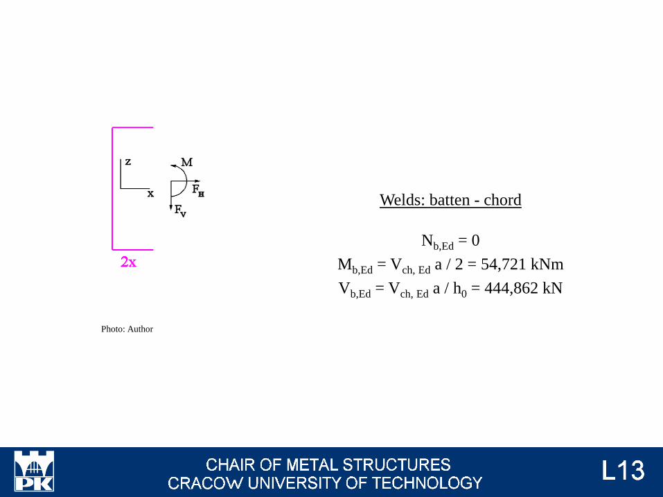
Welds: batten - chord
Nb,Ed = 0
Mb,Ed = Vch, Ed a / 2 = 54,721 kNm
Vb,Ed = Vch, Ed a / h0 = 444,862 kN
Photo: Author

S 235
C 300
Ach = A (C 300) = 58,8 cm2
Jch, y = Jy (C 300) = 7 640 cm4
Jch, z = Jz1 (C 300) = 473 cm4
L = 7,000 m
m = 2
h0 = 1,000 m
a = 1,000 m
NEd = 300,000 kN
VEd = 50,000 kN
Mz, Ed, max = 50 ∙ 7 = 350,000 kNm
n = 2
L 75x75x10
Ad = AV = A (L 75x75x10) =
= 14,1 cm2
d = 1,414 m
Example 2
Photo: Author
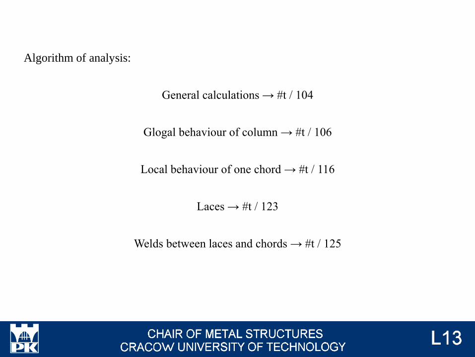
Algorithm of analysis:
General calculations → #t / 104
Glogal behaviour of column → #t / 106
Local behaviour of one chord → #t / 116
Laces → #t / 123
Welds between laces and chords → #t / 125
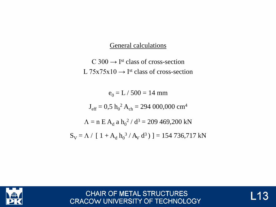
General calculations
C 300 → Ist class of cross-section
L 75x75x10 → Ist class of cross-section
e0 = L / 500 = 14 mm
Jeff = 0,5 h02 Ach = 294 000,000 cm4
L = n E Ad a h02 / d3 = 209 469,200 kN
SV = L / [ 1 + Ad h03 / AV d3 ) ] = 154 736,717 kN
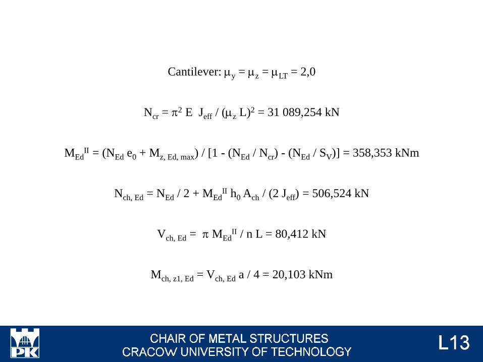
Cantilever: my = mz = mLT = 2,0
Ncr = p2 E Jeff / (mz L)2 = 31 089,254 kN
MEdII = (NEd e0 + Mz, Ed, max) / [1 - (NEd / Ncr) - (NEd / SV)] = 358,353 kNm
Nch, Ed = NEd / 2 + MEdII h0 Ach / (2 Jeff) = 506,524 kN
Vch, Ed = p MEdII / n L = 80,412 kN
Mch, z1, Ed = Vch, Ed a / 4 = 20,103 kNm

Global behaviour of column:
Resistance:
Resistance for axial force → #t / 110
Resistance for shear force → #t / 109
Resistance for bending moments → #t / 110
Interactions between shear force and bending moment, axial force and bending
moment → #t / 110
Stability:
Flexural buckling y-y → #t / 111
Flexural buckling z-z → #t / 112
Torsional buckling → #t / 113
Flexural-torsional buckling → #t / 113
Lateral buckling → #t / 114
Interactions between different types of buckling → #t / 115
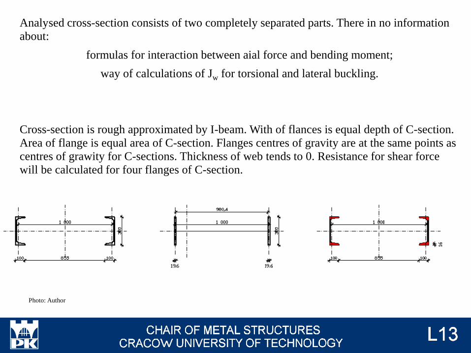
Analysed cross-section consists of two completely separated parts. There in no information
about:
formulas for interaction between aial force and bending moment;
way of calculations of Jw for torsional and lateral buckling.
Cross-section is rough approximated by I-beam. With of flances is equal depth of C-section.
Area of flange is equal area of C-section. Flanges centres of gravity are at the same points as
centres of grawity for C-sections. Thickness of web tends to 0. Resistance for shear force
will be calculated for four flanges of C-section.
Photo: Author
J. Żmuda, „Podstawy projektowania konstrukcji metalowych”, TiT Opole 1992
AV = 4 ∙ 0,1 ∙ 0,016 = 64,000 cm2
Jy = 2 Ach (h0/ 2)2 = 294 000,000 cm4
JW = Jy (100 + 1,96) 2 / 4 = 764 094 358 cm6
JT = 2 ∙ 30 ∙ 1,963 / 3 = 76,832 cm3
Wz, pl = Wimm, pl = 2 Ach (h0/ 2) = 5 880,000 cm3

NRd = 2 Ach fy / gM0 = 2 763,600 kN
VRd = AV fy / (gM0 √3) = 868,335 kN
Mz, Rd = Wimm, pl fy / gM0 = 1381,800 kNm
VEd / VRd = 50,000 / 868,335 = 0,058 < 0,5 → no interaction between VEd and Mz, Ed

a = 2 b = max (5n ; 1,0)
n = NEd / Npl, Rd = 300,000 / 2 763,600 = 0,109 → b = 1,0
a = min [ 0,5 ; (A - 2 b tf) / A]
(A - 2 b tf) / A = (for approximation, thickness of web → 0) = 0,0
a = min [ 0,5 ; 0,0] = 0,0
min ( 0,25 Npl, Rd ; 0,5 hw tw fy / gM0 ) = (for approximation, thickness of web → 0) = 0 kN
NEd > 0 kN → interaction between NEd and Mz, Ed.
MN,z, Rd = min [Mz, Rd ; Mz, Rd (1 - n) / (1 - 0,5 a) ] =
= [1381,800 kNm ; 1381,800 kNm(1 - 0,109) / (1 - 0,5 ∙ 0,0)] = 1231,184 kNm
Mz, Ed / MN, z, Rd = 0,284 ok

y- y (material axis) flexural buckling
NEd = 300,000 kN (→ #t / 102)
NRd = 2 763,600 kN (→ #t / 109)
Jy = 2 Jch, y = 15 280 cm4
Lcr = 2 L = 14,000 m
iy = √ (Jy / A) = √ (2 Jch, y / 2 Ach) = 11,40 cm
ly = 1,308
Buckling curve c → a = 0,49
Fy = 1,627
cy = 0,385
NEd / (cy NRd) = 0,262 < 1,000 ok
Photo: Author

z- z (immaterial axis) flexural buckling
NEd = 300,000 kN (→ #t / 102)
NRd = 2 763,600 kN (→ #t / 109)
Jz = Jeff = 294 000,000 cm4
Lcr = 2 L = 14,000 m
iz = √ (Jz / A) = √ (Jeff / 2 Ach) = 50,00 cm
l = 0,298
Buckling curve c → a = 0,49
F = 0,568
c = 0,951
NEd / (c NRd) = 0,106 < 1,000 ok
Photo: Author

Torsional buckling Ncr, T = [p2 EJw / (mT l0T)2 + GJT] / is2
i0 = √ (iy2 + iz
2) = 51,28 cm
is = √ (i02 + zs
2) = 51,28 cm
Ncr, T = 33 062,163 kN
Flexural-torsional buckling Ncr, z-T = {Ncr, i + Ncr, T - √ [(Ncr, i + Ncr, T)2 - 4 Ncr, i Ncr, T x] } / (2 x)
m = min [√ (mz / mLT) ; √ (mLT / mz)] = 1,0
x = 1 - (m zs2 / is
2) = 1
Ncr, i = min (Ncr, y ; Ncr, z) = Ncr, y = 1 615,795 kN
Ncr, z-T = 3 231,400 kN
Critical forces for torsional buckling and flexural-torsional buckling is bigger than
critical force for flexural buckling → flexural buckling is the most dangerous; there is
no need to control other modes.

Lateral buckling Mcr = is √ (Ncr, i Ncr, T) = 3 747,952 kNm
lLT = √ (MN,z, Rd / Mcr) = 0,607
aLT = 0,76
FLT = [1 + aLT (lLT - 0,2) + lLT2] / 2 = 0,839
cLT = min{ 1 / [FLT + √ (FLT2 - lLT
2)] ; 1,0} = 0,705
cLT, mod = 0,868
cLT, mod MN, z, Rd = 1 199,198 kNm
Cmy = Cmy = 0, 9
CmLT = 0,6
kyy = 1,141
kyz = 0,605
kzy = 0,302
kzz = 0,900
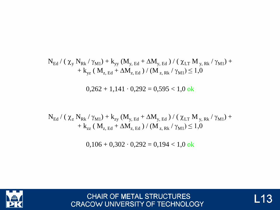
NEd / ( cy NRk / gM1) + kyy (My, Ed + DMy, Ed ) / ( cLT M y, Rk / gM1) +
+ kyz ( Mz, Ed + DMz, Ed ) / (M z, Rk / gM1) ≤ 1,0
0,262 + 1,141 ∙ 0,292 = 0,595 < 1,0 ok
NEd / ( cz NRk / gM1) + kzy (My, Ed + DMy, Ed ) / ( cLT M y, Rk / gM1) +
+ kzz ( Mz, Ed + DMz, Ed ) / (M z, Rk / gM1) ≤ 1,0
0,106 + 0,302 ∙ 0,292 = 0,194 < 1,0 ok

Local behaviour of column:
Resistance:
Resistance for axial force → #t / 119
Resistance for shear force → #t / 118
Resistance for bending moments → #t / 119
Interactions between shear force and bending moment, axial force and bending
moment → #t / 119
Stability:
Flexural buckling z1-z1 → #t / 120
Torsional buckling → #t / 121
Flexural-torsional buckling → #t / 121
Lateral buckling → #t / 122

Analysed cross-section C-section. There is no information about:
formulas for interaction between axial force and bending moment;
Cross-section is rough approximated by I-beam. Resistance for shear force will be calculated
for two flanges of C-section.
Photo: Author
AV = 2 ∙ 0,1 ∙ 0,016 = 32,000 cm2
JW (C 300) = Jy (24,6 + 1,96) 2 / 4 = 73 400 cm6
JT = 2 ∙ 30 ∙ 1,963 / 3 = 40,500 cm3
Wpl, z1, min = 28,812 cm3

NRd = Ach fy / gM0 = 1 381,800 kN
VRd = AV fy / (gM0 √3) = 434,167 kN
Mz, Rd = Wimm, pl fy / gM0 = 6,771 kNm
Vch, Ed / VRd = 80,412 / 434,167 = 0,185 < 0,5 → no interaction between VEd and Mz, Ed
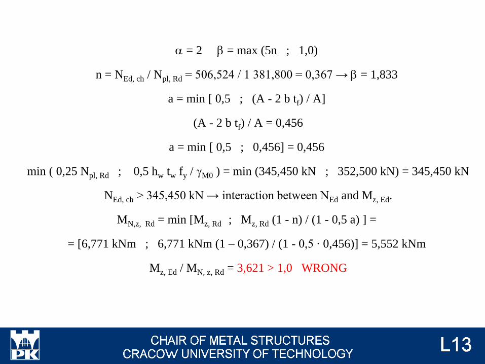
a = 2 b = max (5n ; 1,0)
n = NEd, ch / Npl, Rd = 506,524 / 1 381,800 = 0,367 → b = 1,833
a = min [ 0,5 ; (A - 2 b tf) / A]
(A - 2 b tf) / A = 0,456
a = min [ 0,5 ; 0,456] = 0,456
min ( 0,25 Npl, Rd ; 0,5 hw tw fy / gM0 ) = min (345,450 kN ; 352,500 kN) = 345,450 kN
NEd, ch > 345,450 kN → interaction between NEd and Mz, Ed.
MN,z, Rd = min [Mz, Rd ; Mz, Rd (1 - n) / (1 - 0,5 a) ] =
= [6,771 kNm ; 6,771 kNm (1 – 0,367) / (1 - 0,5 ∙ 0,456)] = 5,552 kNm
Mz, Ed / MN, z, Rd = 3,621 > 1,0 WRONG

z1- z1 flexural buckling
Nch, Ed = 506,524 kN (→ #t / 105)
NRd = 1 381,800 kN (→ #t / 118)
Jch, z = Jz1 (C 300) = 473 cm4
Lcr, z1 = a = 1,000 m
mz1 = 1,0
iz1 = √ (Jz1 / Ach) = 2,84 cm
l = 0,375
Buckling curve c → a = 0,49
F = 0,613
c = 0,911
NEd / (c NRd) = 0,402 < 1,000 ok
Photo: Author

Torsional buckling Ncr, T = [p2 EJw / (mT l0T)2 + GJT] / is2
i0 = √ (iy2 + iz
2) = 12,05 cm
is = √ (i02 + zs
2) = 15,51 cm
Ncr, T = 141 009,672 kN
Flexural-torsional buckling Ncr, z-T = {Ncr, z1 + Ncr, T - √ [(Ncr, z1 + Ncr, T)2 - 4 Ncr, z1 Ncr, T x] }/(2 x)
m = min [√ (mz / mLT) ; √ (mLT / mz)] = 1,0
x = 1 - (m zs2 / is
2) = 0,954
Ncr, z1 = 9 336,646 kN
Ncr, z-T = 17 756,694 kN
Critical forces for torsional buckling and flexural-torsional buckling is bigger than
critical force for flexural buckling → flexural buckling is the most dangerous; there is
no need to control other modes.

Lateral buckling: bending moment acts about weak axis. Because of this, there is no laeral
buckling and no interaction between flexural and lateral buckling.

Laces resistance
VEd = p MEdII / (n L) = 117,643 kN
Cross section: L 75x75x10
NRd = Ad fy = 331,350 kN
Compression:
Horizontal bar
Nl, Ed = VEd
Lcr = 1,000 m
m = 1,0
Cross bar
Nl, Ed = VEd / cos 45o
Lcr = 1,414 m
m = 1,0
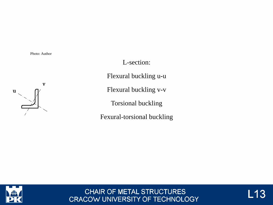
L-section:
Flexural buckling u-u
Flexural buckling v-v
Torsional buckling
Fexural-torsional buckling
Photo: Author

Welds: laces-chord
Nl, Ed
Ml,Ed = 0 kNm
Vl,Ed = 0 kN
l1 d1 = l2 d2Photo: Author
l1
l2
d1
d2

NEd / NRd C → #t / 86 C → #t / 110
VEd / VRd C → #t / 85 C → #t / 109
MEd / MRd D → #t / 86 C → #t / 110
VEd ↔ MEd C → #t / 85 C → #t / 109
NEd ↔ MEd D → #t / 86 C → #t / 110
Flexural buckling y-y C → #t / 87 C → #t / 111
Flexural buckling z-z C → #t / 88 C → #t / 112
Torsional buckling C → #t / 89 C → #t / 113
Flexural-torsional C → #t / 89 C → #t / 113
Lateral buckling D → #t / 90 C → #t / 114
Flexural ↔ lateral D → #t / 91 C → #t / 115
Conclusions – global behaviour
Photo: EN 1993-1-1 fig 6.7
NEd / NRd D → #t / 95 C → #t / 119
VEd / VRd C → #t / 94 C → #t / 118
MEd / MRd D → #t / 95 D → #t / 119
VEd ↔ MEd C → #t / 94 C → #t / 118
NEd ↔ MEd D → #t / 95 D → #t / 119
Flexural buckling z1-z1 D → #t / 96 C → #t / 120
Torsional buckling C → #t / 97 C → #t / 121
Flexural-torsional C → #t / 97 C → #t / 121
Lateral buckling C → #t / 97 C → #t / 122
Flexural ↔ lateral C → #t / 98 C → #t / 122
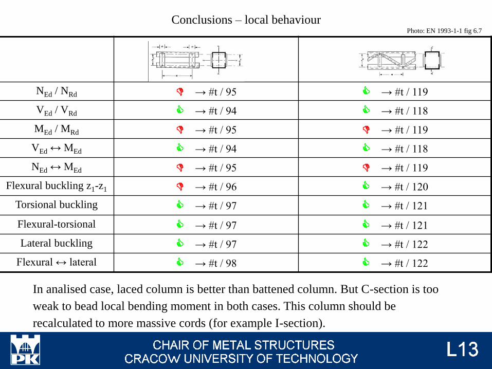
Conclusions – local behaviourPhoto: EN 1993-1-1 fig 6.7
In analised case, laced column is better than battened column. But C-section is too
weak to bead local bending moment in both cases. This column should be
recalculated to more massive cords (for example I-section).
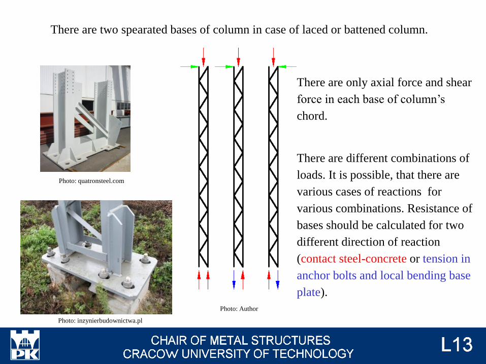
There are two spearated bases of column in case of laced or battened column.
Photo: Author
There are only axial force and shear
force in each base of column’s
chord.
There are different combinations of
loads. It is possible, that there are
various cases of reactions for
various combinations. Resistance of
bases should be calculated for two
different direction of reaction
(contact steel-concrete or tension in
anchor bolts and local bending base
plate).
Photo: quatronsteel.com
Photo: inzynierbudownictwa.pl
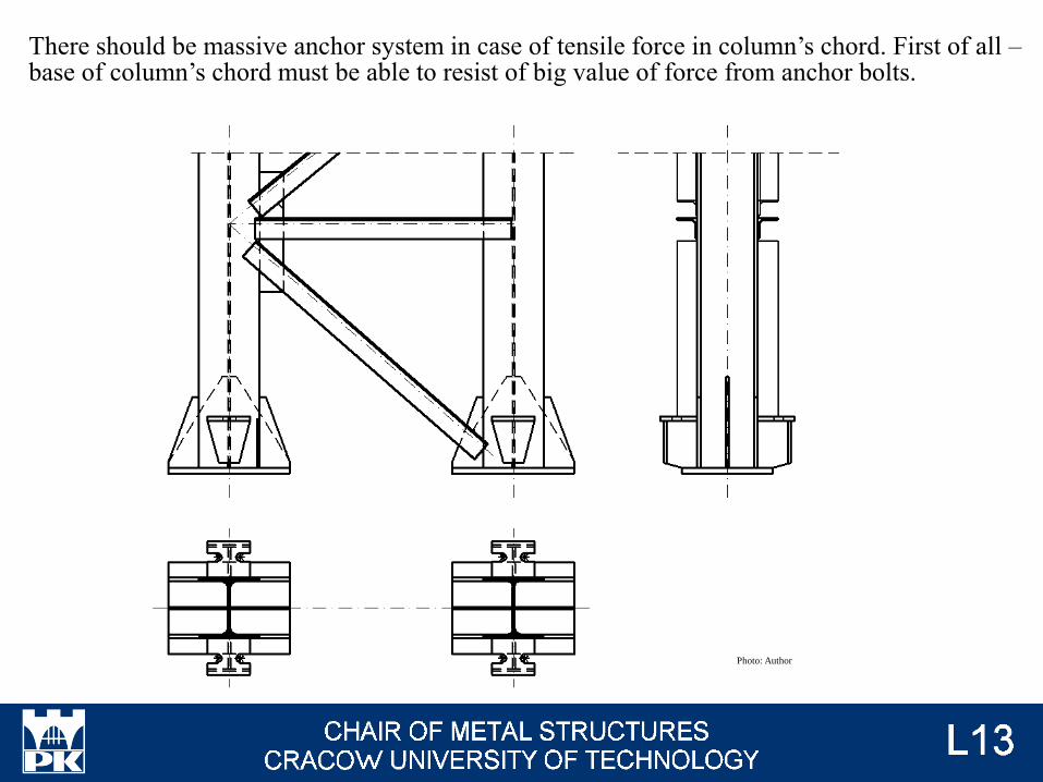
There should be massive anchor system in case of tensile force in column’s chord. First of all –base of column’s chord must be able to resist of big value of force from anchor bolts.
Photo: Author

Anchoring in the concrete foundation is solved in various ways. The easiest - for small
forces - it is the friction between anchor bolts and concrete and resistance of the extended
tip of the bolts.
Photo: Post-installed concrete anchors in nuclear power plants: Performance and qualification, Ph.
Mahrenholtz, R. Eligehausen Nuclear Engineering and Design 287 / 2015

There are used J-anchor bolts for big value of force. These anchors can be weld to the
reinforced steel of base
Photo: peikko.caPhoto: civil-engg-world.blogspot.com
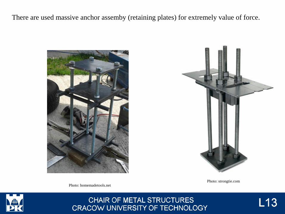
There are used massive anchor assemby (retaining plates) for extremely value of force.
Photo: homemadetools.netPhoto: strongtie.com

Resistance of bases are calculate constant value of stresses under base plate.
Loading Lever arms Resistance Mj, Rd
Left-C, Right-C, exampe:
MEd > 0 ; NEd < 0 z = zC, l + zC, r
e = MEd / NEd
NEd ≤ 0 0 < e < zC, l NEd ≤ 0 -zC, r < e ≤ 0
min [ -z FC, l, Rd / (1 + zC, r / e)
-z FC, r, Rd / (-1 + zC, l / e)]
min [ -z FC, l, Rd / (1 + zC, r /
e)
-z FC, r, Rd / (-1 + zC, l / e)]
Left-T, Right-T, exampe:
MEd > 0 ; NEd > 0 z = zT, l + zT, r
e = MEd / NEd
NEd > 0 0 < e < zT, l NEd > 0 -zT, r < e ≤ 0
min [ z FT, l, Rd / (1 + zT, r / e)
z FT, r, Rd / (-1 + zT, l / e)]
min [ z FT, l, Rd / (1 + zT, r / e)
z FT, l, Rd / (-1 + zT, l / e)]
EN 1993-1-8 tab. 6.7
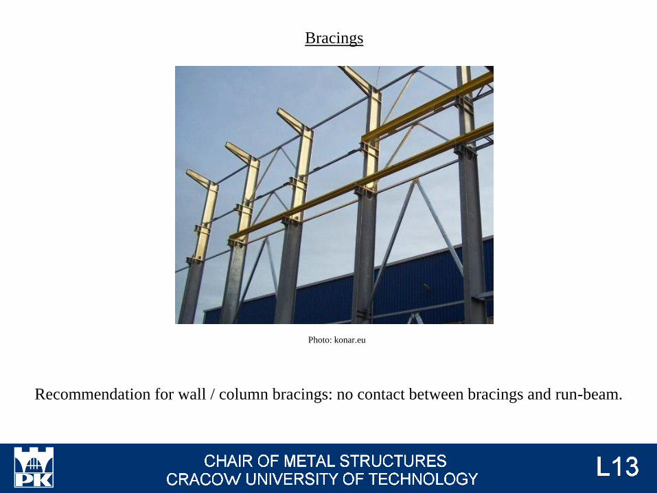
Bracings
Recommendation for wall / column bracings: no contact between bracings and run-beam.
Photo: konar.eu

Contact between bracings and run-beam → multi-span run-beam.
There is one-span run-beam recommended for fatigue calculations (#t / 24 - 25).
Additionally, on bracings act directly vertical loads from crane.
Photo: Author

Recommended shape of bracings
Distance between columns ≤ 6,0 m Distance between columns > 6,0 m
Photo: Author

Fatigue calculations for crane runbeams
Displacements and deformations of crane supporting structures
Laced column and battened column – similiarities and differeces
Algorithm of calculation for laced column
Algorithm of calculation for battened column
Examination issues

Surge connectors - podporowe elementy złączneButt weld - spoina czołowaFilled weld - spoina pachwinowaNotch - karb Laced members - słup wielogałęziowy skratowany Battened members - słup wielogałęziowy z przewiązkami Closely spaced build-up members - pręt wielogałęziowyShear stiffeness - sztywność postaciowaEfficency factor - wskaźnik efektywności