Instructions for Use - Krell Industries Five-Channel Power Amplifier Instructions for Use v 00.0...
28
Leaderin Audio Engineering KAV-1500 Five-Channel Power Amplifier Instructions for Use Owner’s Reference
Transcript of Instructions for Use - Krell Industries Five-Channel Power Amplifier Instructions for Use v 00.0...

Leader in Audio Engineering
KAV-1500Five-Channel Power Amplifier
Instructions for Use
Owner’s Reference

KAV-1500Five-Channel Power Amplifier
Instructions for Usev 00.0
Krell Industries, Inc.45 Connair RoadOrange, CT 06477-3650 USA
TEL 203-799-9954FAX 203-891-2028E-MAIL [email protected] http://www, krellonline.com
This product complies with the EMC directive (89/336/EEC) and the low-voltage directive (73/23/EEC).
WARNINGSThe amplifier must be placed on a firm,/eve/surface where it is not exposed to dt~pping or splashing.
The ventilation grids on the top of the amplifier and the space underneath the amplifier must be unobstructedat all times during operation. Do not place flammable material above or beneath the amplifier.
Contact your authorized Krel/ dealer, distributor, or Krell before using any devices designed to alter or stabi-lize the AC power for the KAV-1500.
Before connecting the KAV-1500, make sure the amplifier is turned off and any output device (such as preamplifier) is in mute or stand-by mode. Make sure all cable terminations are of the highest quality andfree from frayed ends, short circuits, or cold solder joints.
Use only one set of inputs to the amplifier at a time.
After reconfiguring for MAT, do not use more than one input at a time.
After bridging, one channel must remain unbridged.
THERE ARE NO USER SERVICEABLE PARTS INSIDE ANY KRELL PRODUCT.
Please contact your authorized Krell dealer, distributor, or Krell if you have any questions not addressed inthis reference manual.
This product is manufactured in the United States of Amedca. Krell® is a registered trademark of Krell Industries, Inc., and is restricted for use by KrellIndustries, Inc., its subsidiaries, and authorized agents. Multi Amp ThroughputTM is a trademark of Krell Industries, Inc. All other trademarks and tradenamesare registered to their respective companies.
© 2000 by Krell Industries, Inc. All rights reserved P/N 303961
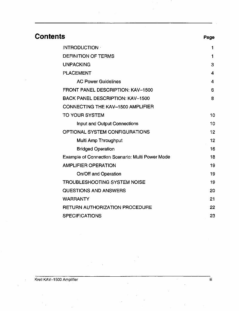
ContentsINTRODUCTION
DEFINITION OF TERMS
UNPACKING
PLACEMENT
AC Power Guidelines
FRONT PANEL DESCRIPTION: KAV-1500
BACK PANEL DESCRIPTION: KAV-1500
CONNECTING THE KAV-1500 AMPLIFIER
TO YOUR SYSTEM
Input and Output Connections
OPTIONAL SYSTEM CONFIGURATIONS
Multi Amp Throughput
Bridged Operation
Example of Connection Scenario: Multi Power Mode
AMPLIFIER OPERATION
On/Off and Operation
TROUBLESHOOTING SYSTEM NOISE
QUESTIONS AND ANSWERS
WARRANTY
RETURN AUTHORIZATION PROCEDURE
SPECIFICATIONS
Page
1
1
3
4
4
6
8
10
10
12
12
16
18
19
19
19
20
21
22
23
Krell KAV-1500 Amplifier iii

Illustrations
FIGURE 1
FIGURE 2
FIGURE 3
FIGURE 4
The KAV-1500 Front Panel
The KAV-1500 Back Panel
Reconfiguring the KAV-1500 for MAT Operation
Reconfiguring the KAV-1500 for Bridged Operation
Page
5
7
13
15
iv Krell KAV-1500 Amplifier

IntroductionThank you for your purchase of.the Krell KAV-1500 Five-Channel Power Amplifier.
The KAV-1500 amplifier provides substantial five-channel output power that deliversrealistic music reproduction at an exceptional value. The amplifier can be customizedwith a variety of optional system configurations, including a multi power mode using theMulti Amp Throughput (MAT) feature, and bridged operation. The KAV-1500 amplifierhas balanced and single-ended inputs for compatibility with other components. Themulti-channel (DB-25) input also allows you to integrate the amplifier easily andseamlessly into home theater or whole house systems. The amplifier can be operatedusing the 12 VDC power on/off (12 V trigger) signals from other components.
This reference manual contains important information on placement, installation, andoperation of the KAV-1500 amplifier. Please read this information carefully. A thoroughunderstanding of these details helps ensure satisfactory operation and long life for yourKAV-1500 amplifier and related system components.
Definition of Terms
Following are the definitions of key terms used in your owner’s reference manual.
CONNECTIONSBridgingA method of linking two amplifier channels by distributing the speaker load between thepositive binding posts. Bridging the channels quadruples the power rating at 8 Ohms.Bridged configurations should not be used with loads under 4 Ohms.
Krell Multi Amp Throughput (MAT)An internal connection option that sends the same music signal to all amplifier channelsusing one balanced or single-ended connection. MAT reduces installation complexityand cabling requirements in systems containing multiple amplifiers. MAT also allows avariety of connection scenarios, including powering multiple pairs of loudspeakers toextend the listening environment throughout your home.
INPUTS AND OUTPUTS
BalancedA symmetrical input or output circuit that has equal impedance from both input terminalsto a common ground reference point. The industry standard for professional and soundrecording installations, balanced connections have 6 dB more gain than single-endedconnections and allow the use ofr long interconnect cables.
Krell KAV-1500 Amplifier 1

Definition of Terms, continued
Single-endedA two-wire input or output circuit, Use care when using single-ended connections, inwhich the ground, connection is made last and broken first. Turn the system off prior tomaking or breaking single-ended connections. Single-ended connections are notrecommended for configurations requiring long cable runs.
Multi-channel (DB-25)A balanced input or output circuit that allows for the simultaneous connection of allaudio outputs plus one 5 VDC (5 Volt tdgger) via a single cable. DB-25 inputs andoutputs are becoming popular for connecting multi-channel AN processors and poweramplifiers, simplifying the integration of the two components into your system.
OPERATION
OffWhen the power button on the front panel is pressed and the blue power LED turns off,the component is off.
Operational ModeWhen the power button on the front panel is pressed and the blue power LEDilluminates, the component is in the operational mode and ready to play music.
Stand-by ModeA low power consumption status that keeps the audio and regulator circuits at idle. Krellrecommends leaving the component in the stand-by mode when it is not playing music.
2 Krell KAV-1500 Amplifier

Unpacking
Open the shipping box, which contains:1 amplifier unit (packed in foam end-caps)4 ribbon connection cablesFuses
2 AGC- ~ (~-amp) speaker fuse1 slow-blow (20 amp for 100/120V or 12 amp for 220/240V) line fuse
1 12 VDC output (12 V trigger) cable1 T-15 Torx wrench1 packet containing the owner’s reference manual and the warranty registrationcard.
IMPORTANTTwo people are needed to remove the amplifier from the shipping box.
1. One person grasps the underside of the foam end-caps at one end of the amplifier;at the same time, the second person grasps the underside of the foam end caps atthe other end of the amplifier.
2. Slowly lift the amplifier straight out of the shipping box.3. Place the amplifier in a safe location and remove the protective plastic wrapping.
Notes/f any of these items are not included in the shipping box, please contact yourauthorized Krell dealer, distributor, or Kre// for assistance.Save all packing materials. If you ship your amplifier in the future, repack the unit in itsoriginal packaging to prevent transit damage. See Return Authorization Procedure,on page 22, for more information.
Krell KAV-1500 Amplifier 3

Placement
Before you integrate the KAV-1500 into your system, review the following guidelines tochoose the location for the component. This will facilitate a clean, trouble-freeinstallation.
The KAV-1500 requires at least two inches (5 cm) of clearance on each side and least two inches (5 cm) of clearance above the component to provide adequateventilation.
The KAV-1500 does not require any type of special rack or cabinet for installation. Forthe dimensions of your amplifier see Specifications, on page 23.
Place the amplifier as close to the loudspeakers as possible and keep the speakercable length to a minimum. Speaker cable adds impedance to the load the amplifiermust drive, regardless of the cable’s gauge. Krell amplifiers drive the lowestimpedances with ease, but long speaker cables reduce the maximum power that isdelivered to the loudspeakers.
AC POWER GUIDELINESKrell recommends operating each amplifier from a dedicated 15-amp AC power line.For maximum power output, operate the KAV-1500 amplifier from a dedicated 20-ampAC power line.
4 Krell KAV-1500 Amplifier

FIGURE 1 THE KAV-1500 FRONT PANEL
KAV- 1500
1 Power Button2 Power LED

Front Panel Description: KAV-1500
See Figure 1 on page 5
1 Power ButtonUse this button to switch the KAV-1500 power from off to the operational mode andalso to switch the 12 VDC output (12 V trigger) on and off.2 Power LEDThe blue power LED illuminates when the amplifier is in the operational mode,
6 Krell KAV-1500 Amplifier

FIGURE 2 THE KAV-1500 BACK PANEL
3 8
AGC-12
20 23 19 14
9
INPUT---~
/
AGC-12
5 10/
r-~ ~ INPUT ~/
6 11 7 12
KAV-1500Power Amplifier
21 22
OUTPUT(LIEF’I" SURROUNO)
19 15 1916 1917
AGC42
OUTPUT(LEF’r)
1918
Balanced Inputs3 Right Surround Input4 Left Surround Input5 Center Input6 Right Input7 Left InputSingle-ended Inputs8 Right Surround Input9 Left Surround Input10 Center Input11 Right Input12 Left InputMulti-Channel Input13 Multi-channel Input
Amplifier Channel Outputs14 Right Surround Output15 Left Surround Output16 Center Output17 Right Output18 Left OutputFuses19 AGC-~uses "-,20 Line FuseRemote Connections21 12 VDC Remote
Power Out22 12 VDC Remote
Power InPower23 AC Power Cord

Back Panel Description: KAV-1500See Figure 2 on page 7The KAV-1500 back panel provides connections for all inputs and outputs, remoteconnection input and output links, and AC power supply.
Balanced Inputs3, 4, 5, 6, 7 InputsThese are the right surround (3), left surround (4), center (5), right (6), and KAV-1500 channel inputs for output devices with balanced XLR connectors.
Single-ended Inputs8, 9, 10, 11, 12 InputsThese are the right surround (8), left surround (9), center (10), right (11), and left KAV-1500 channel inputs for output devices with single-ended RCA connectors.
See Reconfiguring the KA V-1500 for MAT, on page 14, and Reconfiguring theKAV-1500 for Bridged Operation, on page 16, for information on optional systemconfigurations.
Multi-channel Input13 Multi-channel InputThis is the DB-25 input, for connecting to the DB-25 output of a preamp/processor. TheDB-25 input incorporates all five channels plus a 5 VDC (5 Volt trigger), and allows youto send all audio signals and turn the amplifier on and off via a single cable.
Amplifier Channel Outputs14, 15, 16, 17, 18 OutputsThese are the right surround (14), left surround (15), center (16), right (17), and left KAV-1500 amplifier channel outputs with five-way loudspeaker binding posts. Theloudspeaker binding post terminals accept spade lugs, bare wire, banana plugs, orpins. Use the red terminal for the positive connection and the black terminal for thenegative connection.
See Input and Output Connections, on page 10, Connecting the KA V-1500Reconfigured for MAT, on page 14, and Connecting the Bridged KA V-1500, onpage 17, for more information on amplifier channel output connections.
8 Krell KAV-1500 Amplifier

Back Panel Description, continued
Fuses19 AGC-12 FusesThe AGC 12 Volt loudspeaker fuses protect the KAV-1500 against short circuits inloudspeaker output.
20 Line FuseThe line fuse protects the KAV-1500 against short circuits in internal power supplies,
NoteFuses must be replaced with the fuse value specified on the KA V-1500 back panelUse a 20 amp slow-blow line fuse for 100/120 V systems or a 12 amp slow-blow linefuse for 220/240 V systems,
Remote Connections21 12 VDC Remote Power OutThe KAV-1500 is equipped with an output that sends 12 VDC power on/off (12 trigger) signals to other Krell components and other devices that incorporate a 12 trigger.
22 12 VDC Remote Power InThe KAV-1500 is equipped with an input that receives 12 VDC power on/off (12 trigger) signals from other Krell components and other devices that incorporate a 12 trigger. This allows you to turn the KAV-1500 on and off using a Krell or othercomponent in a custom installation.
Notes12 VDC Out~In (12 V trigger) remote power is limited to 30 ma.
Consult the owner’s manual of each component used in a custom installation to take fulladvantage of the KA V-1500 remote capability.
Power23 AC Power CordThe KAV-1500 is equipped with a hardwired AC power cord,
Krell KAV-1500 Amplifier

Connecting the KAV-1500 Amplifier to Your System
INPUT AND OUTPUT CONNECTIONS
Follow these steps to connect the KAV-1500 amplifier to your system.1. Make sure all power sources and components are off before connecting inputs and
outputs=2. Neatly organize the wiring between the amplifier and all system components.
Separate AC wires from audio cables to prevent hum or other unwanted noise frombeing introduced into the system,
3. Connect the interconnect cables from your output device to the amplifier inputs. TheKAV-1500 is equipped with balanced (3, 4, 5, 6, 7) or single-ended (8, 9, 10, 11, inputs located on the back panel. The balanced inputs use three-pin XLRconnectors; the single-ended inputs use RCA connectors.orUse the multi-channel (DB-25) connector to simplify the integration of the KAV-1500into your system.
Connect the DB-25 output on your preamp/processor to the DB-25 input (13)located on the back panel of the KAV-1500. The DB-25 cable simultaneouslytransmits audio outputs and Trigger 1 signals from the Krell Home Theater StandardSurround Preamp/processor (HTS) DB-25 output to all inputs and a 5 VDC (5 Volttrigger) on the KAV-1500 via the DB-25 input.
NoteYou need to configure Trigger 1 on the HTS before operation.
IMPORTANTDo not connect the multi-channel input and single-ended or balanced inputs at thesame time.
4. Connect the loudspeaker cables to the KAV-1500 amplifier channel output speakerbinding posts (14, 15, 16, 17, 18)located on the back panel.The amplifier channel outputs for the KAV-1500 use five-way loudspeaker bindingposts. The loudspeaker binding post terminals accept spade lugs, bare wire, bananaplugs, or pins. Use the red terminal for the positive connection and the blackterminal for the negative connection.
5. Plug the end of the AC power cord into the AC outlet.The amplifier is now ready for operation. See Amplifier Operation, on page 19.
1 o Krell KAV-1500 Amplifier

The KAV-1500 amplifier is shipped with shorting pins in the XLR inputs. These pinsshould remain in the XLR inputs if the amplifier is operating in the single-ended mode.When the shorting pin is insert,ed, pins 1 (lower left) and 3 (top) are shorted together.Remove the shorting pins to connect the amplifier for balanced operation.The XLR pin configuration is described below:
Pin 1 GroundPin 2 Non-inverting (0°)Pin 3 Inverting (180°)
Krell recommends using balanced interconnect cables. Balanced interconnect cablesnot only can minimize sonic loss but are also immune to induced noise, especially withinstallations using long cables. Balanced connections have 6 dB more gain than single-ended connections. When level matching is critical, keep this gain value in mind.
Krell KAV-1500 Amplifier 11

Optional System Configurations
The KAV-1500 can be reconfigured for either Multi Amp Throughput (MAT) or bridgedoperation.
IMPORTANTRemoving the cover to reconfigure for MAT or for bridged operation is the ONLYinstance you are authorized to remove the cover of ANY Krell component withoutvoiding your Warranty. For more information on product limitations and restrictions, seeWarranty, on page 21.
Before Reconfiguring for MAT or Bridged OperationRead the following important safety instructions before you attempt to reconfigure youramplifier for either MAT or bridged operation:1. Unplug the power cord. Unplug the AC power cord (23) from AC power.
2. Avoid the power supply. After removing the screws (see instructions below) andthe cover, locate and stay aware of the location of the power supply (round, silverstructures behind the amplifier front panel). Avoid making contact with that area ofthe amplifier.
3. Remove jewelry. Rings, necklaces, bracelets, and other pieces of metal jewelrycan conduct an electrical charge. Consider removing them before attempting anyreconfiguration.
4. Always replace cover, Make sure the amplifier’s cover is properly replaced andsecured by all 14 cover screws before resuming operation.
IMPORTANTOperating the amplifier without the cover properly replaced and secured mayvoid your warranty.
MULTI AMP THROUGHPUTMulti Amp Throughput (MAT) is an internal connection option for the KAV-1500 thatlets you send the same music signal to all amplifier channels using one balanced orsingle-ended connection. MAT reduces installation complexity and cabling requirementsin systems containing multiple amplifiers.
12 Krell KAV-1500 Amplifier

FIGURE 3 RECONFIGURING THE KAV-1500 FOR MAT OPERATI()N
PC Input Board showing MAT jumper configuration
Left To SlowChannel Start
J1M8oard
For J For ~,~eff. SurroundJ For~ RightBridging Surround
J6fl J4N ,,,J5 J7111 J12,, J11,llJ1,II J13,1, J1811 Jr6111 CRj17 I~L~piiTB~5/~ES J~i’ng J19~ ~J23 ~:0~i~2~ I]J29 IIIJ25
PRC - Permanent ribbon connections (Do Not Remove)
MAT - Multi Amp Throughput (MAT) ribbon connections
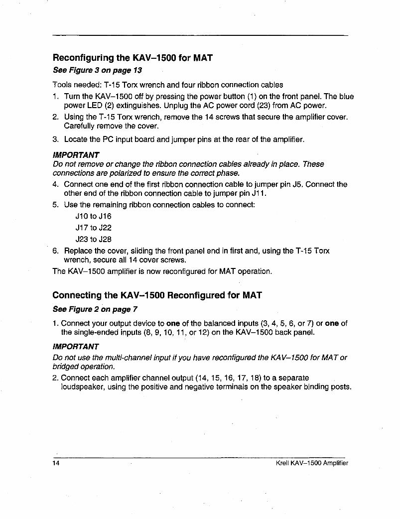
Reconfiguring the KAV-1500 for MATSee Figure 3 on page 13
Tools needed: T-15 Torx wrench and four ribbon connection cables
1. Turn the KAV-1500 off by pressing the power button (1) on the front panel. The bluepower LED (2) extinguishes. Unplug the AC power cord (23) from AC power.
2. Using the T-15 Torx wrench, remove the 14 screws that secure the amplifier cover.Carefully remove the cover.
3. Locate the PC input board and jumper pins at the rear of the amplifier.
IMPORTANTDo not remove or change the ribbon connection cables already in place. Theseconnections are polarized to ensure the correct phase.4. Connect one end of the first ribbon connection cable to jumper pin J5. Connect the
other end of the ribbon connection cable to jumper pin J11.
5. Use the remaining ribbon connection cables to connect:J10 to J16J 17 to J22
J23 to J286. Replace the cover, sliding the front panel end in first and, using the T-15 Torx
wrench, secure all 14 cover screws.The KAV-1500 amplifier is now reconfigured for MAT operation.
Connecting the KAV-1500 Reconfigured for MAT
See Figure 2 on page 7
1. Connect your output device to one of the balanced inputs (3, 4, 5, 6, or 7) or one the single-ended inputs (8, 9, 10, 11, or 12) on the KAV-1500 back panel.
IMPORTANTDo not use the multi-channel input if you have reconfigured the KA V-1500 for MAT orbridged operation.2. Connect each amplifier channel output (14, 15, 16, 17, 18) to a separate
loudspeaker, using the positive and negative terminals on the speaker binding posts.
14 Krell KAV-1500 Amplifier

FIGURE 4 RECONFIGURING THE KAV-1500 FOR BRIDGED OPERATI( )N
Do not attempt to bridge channels in any way other than specified below.
Opt I
Opt~ Opti°n 2
Right For Center For ForChannel Bridging Channel Bridging KRELLINDUSTRIES Bridging
J,~ J12fl J11~11(~] ,13~ J18H J16fl H J17 1"%7BOA05BRD J24N
!Left To Slow For
Channel Stad Bridgingm Board
Option 4i
Left Surround For Right
Option 1: Bridging r----BRGthe Left andRight Channels
,~ Bri~ (~l~;~e, Bri~ing~/ J6111 J411 IIJ5 J7111 J1211 J11111
~__~-- PRC
Option 3: Bridging I-~-BRGthe Center and Left ~....-L....~..~Surround Channels f
-~
1418111 J1611 II317 P10705B J2411 J19111J2211 111423 I
~__~--- PRC
Option 2: Bridging r----BRGthe Right and ~Center Channels
f ~I For / ..... =..X /
/ J12111 J1111J1qlJ13111 J1811 J1611 IIIJ17
Option 4: Bridging I---BRGthe Left Surround and ~Right Surround Channels /
~For ~ Left For~
~ Bridgin~"~Su~und n n Bd~]ing n~| 324111 31911132211 ii323 3301132811 iii329
~__~-PRC
PRC -- Permanent ribbon connections (Do Not Remove) BRG -- Bridging

BRIDGED OPERATION
The KAV-1500 can be reconfigured to bridge four of its amplifier channels to operateas two combined amplifier channels. The bridged amplifier channels each deliver 1,100Watts into an 8 Ohm load. The unbridged amplifier channel can be connected to aseparate loudspeaker.
IMPORTANTOne channel must remain unbridged.
Reconfiguring the KAV-1500 for Bridged Operation
See Figure 4 on page 15
Tools needed: T-15 Torx wrench and two ribbon connection cables1. Turn the KAV-1500 off by pressing the power button (1) on the front panel. The blue
power LED (2) extinguishes. Unplug the AC power cord (23) from AC power.2. Using the T-15 Torx wrench, remove all 14 cover screws that secure the amplifier
cover. Carefully remove the cover.3. Locate the PC input board and jumper pins at the rear of the amplifier.4. Follow the directions below. You may bridge channels using:
Options 1 and 3 or Options 1 and 4 or Options 2 and 4
IMPORTANTDo not attempt to bridge channels in any way other than specified in these directions.
Option 1: To bridge the left and right channels, connect one end of the ribbonconnection cable to jumper pin J6. Connect the other end of the ribbon connectioncable to jumper pin J11.Option 2: To bridge the right and center channels, connect one end of the ribbonconnection cable to jumper pin J12. Connect the other end of the ribbon connectioncable to jumper pin J17.Option 3: To bridge the center and left surround channels, connect one end of theribbon connection cable to jumper pin J18. Connect the other end of the ribbonconnection cable to jumper pin J23.Option 4: To bridge the left surround and right surround channels, connect oneend of the ribbon connection cable to jumper pin J24. Connect the other end of theribbon connection cable to jumper pin J29.
5. Replace the cover and, using the T-15 Torx wrench, secure all 14 cover screws.The KAV-1500 amplifier is now ready for bridged operation.
16 Krell KAV-1500 Amplifier

Connecting the Bridged KAV-1500See Figure 2 on page 7
Connect the bridged channels as follows:
Option 11. When the left and right channels are bridged, connect the output cable from the
output device to the appropriate balanced (7) or single-ended (12) left channel input.
2. Connect the positive loudspeaker lead (red) to the positive binding post on the leftamplifier channel (18), Connect the negative loudspeaker lead (black) to the positivebinding post of the right amplifier channel (17).
Option 2
1. When the right and center channels are bridged, connect the output cable from theoutput device to the appropriate balanced (6) or single-ended (1 1) right channeloutput.
2. Connect the positive loudspeaker lead (red) to the positive binding post on the rightamplifier channel (17). Connect the negative loudspeaker lead (black) to the positivebinding post of the center amplifier channel (16).
Option 3
1. When the center and left surround channels are bridged, connect the output cablefrom the output device to the appropriate balanced (5) or single-ended (10) centerchannel input.
2. Connect the positive loudspeaker lead (red) to the positive binding post on the centeramplifier channel (16). Connect the negative loudspeaker lead (black) to the positivebinding post of the left surround amplifier channel (15).
Option 41. When the left surround and right surround channels are bridged, connect the output
cable from the output device to the appropriate balanced (4) or single-ended (9) surround channel input.
2. Connect the positive loudspeaker lead (red) to the positive binding post on the leftsurround amplifier channel (15). Connect the negative loudspeaker lead (black) the positive binding post of the right surround amplifier channel (14).
For each option, the remaining unbridged channel may be connected to a separateloudspeaker for normal operation.
IMPORTANTWhen operating the amplifier in bridged mode and using an output device with asingle-ended RCA cable, be sure to remove the shorting pin from the balanced XLRinput.
Krell KAV-1500 Amplifier 17

Multi Power Mode ConnectionMulti power mode is one possible connection scenario using the KAV-1500’s Multi AmpThroughput (MAT) feature. With Multi Power Mode, you can use the KAV-1500 reconfig-ured for MAT to independently power multiple pairs of stereo loudspeakers, to extend thelistening environment throughout your home. When the KAV-1500 is reconfigured for MAT,each channel powers an individual loudspeaker, with one KAV-1500 dedicated to drivingoutputs to the left loudspeakers and one KAV-1500 driving outputs to the right loudspeak-ers.
The diagram below illustrates this connection scenario:
LivingRoom (L)
Kitchen (L)
Left Speakers
Patio (L)
+ -
Left Amplifier
Gym (L) Bedroom (L)
Right Amplifier
Right Speakers
Bedroom (R)
18 Krell KAV-1500 Amplifier

Amplifier Operation
ON/OFF AND OPERATION
When powering up your system, turn amplifiers on last. When powering down yoursystem, turn amplifiers off first. The procedures for amplifier operation follow.1. Press the power button (1) on the KAV-1500 front panel. The blue power LED (2)
illuminates and you hear a click. The amplifier is now ready for operation.2. With the output device muted or volume control fully lowered, select an output
device. Decrease or increase the volume control to the desired listening level.3. Before turning the system off, mute or lower the output device volume. Press the
front panel power button (1) to turn the amplifier off. It is now safe to turn off the restof the system.
IMPORTANTAlways tum off the amplifier before changing input connections, and mute or fullyattenuate the preamplifier/eve/when switching sources.
The KA V-1500 has tremendous reserves of power and safely drives loudspeakers toextremely high sound pressure levels. However, use care when setting high playbacklevels and lower the volume level at any sign of loudspeaker distress.
Troubleshooting System Noise
When you mix and match high-performance audio components, each with its ownground potential, a low frequency hum may occur in one or all loudspeakers. If thishappens when you place the KAV-1500 into your system, follow these simpletroubleshooting steps.
1. Check that all input and output connections are of sound construction.
2. With the amplifier off, remove the interconnect cables, then turn the amplifier on.If the hum disappears, turn the amplifier off and reinsert one of the interconnectcables. Turn the amplifier back on. Repeat this process for each cable.
3. If the hum reappears with one or both interconnect cables reinserted, the cableneeds to be replaced.
4. If the interconnect cables are sound, you may be experiencing a ground loop.Please contact your authorized Krell dealer, distributor, or Krell for suggestions onhow to eliminate it.
Krell KAV-1500 Amplifier 19

Questions and Answers
Q. Should I leave the KAV-1500 amplifier on at all times?
A. No. The amplifier does not have a stand-by mode. Leaving it on at all times wouldresult in considerable heat output and power consumption. For best results, turn theamplifier off when not in use, and allow a five minute warm-up after it is switched to theoperational mode. See Amplifier Operation, on page 19.
Q. When I turn the amplifier on there is a loud hum through the loudspeakers. Whatshould I do?
A. When a new component is introduced, a low frequency hum may occur in one orboth loudspeakers. Check that all input and output connections and cables are of soundconstruction. See Troubleshooting System Noise, on page 19. If the connections andcables are sound, you may be experiencing a ground loop. This can often be easilyeliminated. Please contact your authorized Krell dealer, distributor, or Krell forsuggestions.
Q. When I connect the amplifier to my system using the single-ended inputs, a loudbuzz comes from my loudspeakers. What is it?
A. Check that the shorting pins for the KAV-1500 are inserted into the XLR inputs (theunit is shipped with the pins in place). When using the single-ended inputs, theseshorting pins must be inserted between pins 1 and 3 to keep external noise fromcorrupting the signal. For more information, see Connecting the KAV-1500 Amplifierto Your System, on page 10.
Q. Can I bridge all the channels on my KAV-1500?
A. The KAV-1500 has five channels. You can bridge four of those channels to operateas two channels. One channel must remain unbridged. See Bridged Operation, onpage 16.Q. I want to bridge the channels on my KAV-1500 but when I open the amplifier, thereare ribbon connection cables already in place. Should I remove them?
A. No. Your amplifier is shipped with ribbon connection cables in place and polarized toensure the correct phase (see Figure 3, on page 13). Do not remove or change theseribbon connection cables. The KAV-1500 is not reconfigured for bridged or Multi AmpThroughput (MAT) operation when it is shipped to you. Use the additional ribbonconnection cables shipped with the amplifier and instructions on pages 12 and 16 toreconfigure the KAV-1500 for bridged or MAT operation.
20 Krell KAV-1500 Amplifier

WarrantyThis Krell product has a limited warranty =of five years forparts and labor on circuitry. Should this product fail to per-form at any time dudng the warranty, Krell will repair it at nocost to the owner, except as set forth in this warranty.
The warranty does not apply to damage caused by acts ofGod or nature.The warranty on this page shall be in lieu of any other war-ranty, expressed or implied, including, but not limited to, anyimplied warranty of merchantability or fitness for a particularpurpose. There are no warranties which exceed beyondthose described in this document. If this product does notperform as warranted herein, the owner’s sole remedy shallbe repair. In no event will Krell be liable for incidental or con-sequential damages arising from purchase, use, or inabilityto use this product, even if Krell has been advised of thepossibility of such damages.Proof of purchase in the form of a bill of sale or receiptedinvoice substantiating that the unit is within the warrantyperiod must be presented to obtain warranty service. Thewarranty begins on the date of retail purchase, as noted onthe bill of sale or receipted invoice from an authorized Krelldealer or distributor.The warranty for Krell products is valid only in the country towhich they were originally shipped, through the authorizedKrell distributor for that country, and at the factory. Theremay be restrictions on or changes to Krell’s warrantybecause of regulations within a specific country. Pleasecheck with your distributor for a complete understanding ofthe warranty in your country.If a unit is serviced by a distributor who did not import theunit, theR may be a charge for service, even if the productis within the warranty period.
FRight to the factory is your responsibility. Return freightwithin the United States (U.S.A.) is included in the warranty.If you have purchased your Krell product outside the U.S.A.and wish to have it serviced at the factory, all freight andassociated charges to the factory are your responsibility.
Krell will pay retum fright to the U.S.A.-based fright for-warder of your choice. Freight and other charges to ship theunit from the freight forwarder to you are also your respon-sibility.Krell is not responsible for any damage incurred in transit.Krell will file claims for damages as necessary for units dam-aged in transit to the factory. You are responsible for filingclaims for shipping damages during the retum shipment.Krell does not supply replacement parts and/or products tothe owner of the unit. Replacement parts and/or productswill be furnished only to the distributor performing service onthis unit on an exchange basis only; any parts and/or prod-ucts returned to Krell for exchange become the property ofKrell.No expressed or implied warranty is made for any Krellproduct damaged by accident, abuse, misuse, natural orpersonal disaster, or unauthorized modification.
Any unauthorized voltage conversion, disassembly,component replacement, perforation of chassis,updates, or modifications performed to the unit willvoid the warranty.The operating voltage of this unit is determined by the fac-tory and can only be changed by an authorized Krell distrib-utor or at the factory. The voltage for this product in theU.S.A. cannot be changed until six months from the originalpurchase date.In the event that Krell receives a product for warranty ser-vice that has been modified in any way without Krell autho-rization, all warranties on that product will be void. The prod-uct will be returned to odginal factory layout specifications atthe owner’s expense before it is repaired. All repairsrequired after the product has been returned to original fac-tory specifications will be charged to the customer, at cur-rent parts and labor rates.
All operational features, functions, and specifications andpolicies are subject to change without notification.
To register your product for warranty benefits,complete and return the WarrantyRegistration Card enclosed in the shippingbox within 15 days of purchase. Thank you.
Krell KAV-1500 Amplifier 21

Return AuthorizationProcedureIf you believe there is a problem with yourcomponent, please contact your dealer, dis-tributor, or the Krell factory to discuss theproblem before you return the component forrepair. To expedite service, you may wish tocomplete and e-mail the Service RequestForm in the Service Section of our websiteat:
http://www.krellonline.com
To contact the Krell Service De 3artment
TEL 203-799-9954Monday-Friday9:00 AM to 5:00 PM EST
FAX 203-799-9796
E-MAIL service@ krellonline.com
WEBSlTE http’J/www.krellonline.com
KAV-1500PRODUCT NAME SERIALNUMBER
To return this product to Krell, pleasefollow this procedure so that we mayserve you better:
1. Obtain a Return Authorization Number(R/A number) and shipping addressfrom the Krell Service Department.
2. Insure and accept all liability for loss ofor damage to this product during ship-ment to the Krell factory and prepay allshipping charges. Please see theWarranty page in this manual, concern-ing liability for shipping damage andshipping charges.
This product may also be hand delivered ifarrangements with the Service Departmenthave been made in advance. Proof of pur-chase will be required for warranty valida-tion at the time of hand delivery.
IMPORTANTUse the original packaging to ensure safetransit of this product to the dealer, distribu-tor, or facto~ Kre// may, at its discretion,return this product in new packaging and billthe owner for such packaging if the productreceived by Krell was boxed in non-stan-dard packaging or if the original packagingwas so damaged that it was unusable. IfKrel/ determines that new packaging isrequired, the owner will be notified beforethis product is returned.
To purchase additional packaging, pleasecontact your authorized Krell dealer, distrib-utor, or the Krell Service Department.
22 Krell KAV-1500 Amplifier

Specifications
KAV-1500 Five-Channel AmplifierFREQUENCY RESPONSE
SIGNAL TO NOISE RATIO
"A" WEIGHTED
TOTAL HARMONIC DISTORTION (THD)
GAIN
INPUT IMPEDANCE
INPUT SENSITIVITY
OUTPUT VOLTAGE
OUTPUT POWER, EACH CHANNEL
DRIVEN
BRIDGED
POWER CONSUMPTION
INPUTS
OUTPUTS
DIMENSIONS
WEIGHT
20 Hz to 20 kHz +0 dB, -0.2 dB
0.4 Hz to 112 kHz +0 dB, -3 dB
118dB
1 kHz < 0.06%
20 kHz < 0.25%
26.4 dB
100 kOhms
2.15 Vrms
Peak to Peak
RMS
8 Ohms
4 Ohms
8 Ohms
Idle
Max.
166 V
59 V
300 W
600 W
1,100 W
280 W
3,460 W
5 single-ended via RCA connectors
5 balanced via XLR connectors
5 via DB-25 connector
5 amplifier channels via five-way speaker
binding posts
19w x 6.3h x 20.25d in.
48.3w x 16h x 51.4d cm
Shipping 125 lb., 56.81 kg
Unit only 108 lb., 49.09 kg
All operational features, functions, specifications,and policies are subject to change without notification.
Krell KAV-1500 Amplifier 23

Krell Industries, Inc.45 Connair RoadOrange, CT 06477-3650 USA
TEL 203-799-9954FAX 203-891-2028E-MAIL krell@ krellonline.comWEBSITE http://www, krellonline.com
KAV-1500Five-Channel Power Amplifier
v 00.0