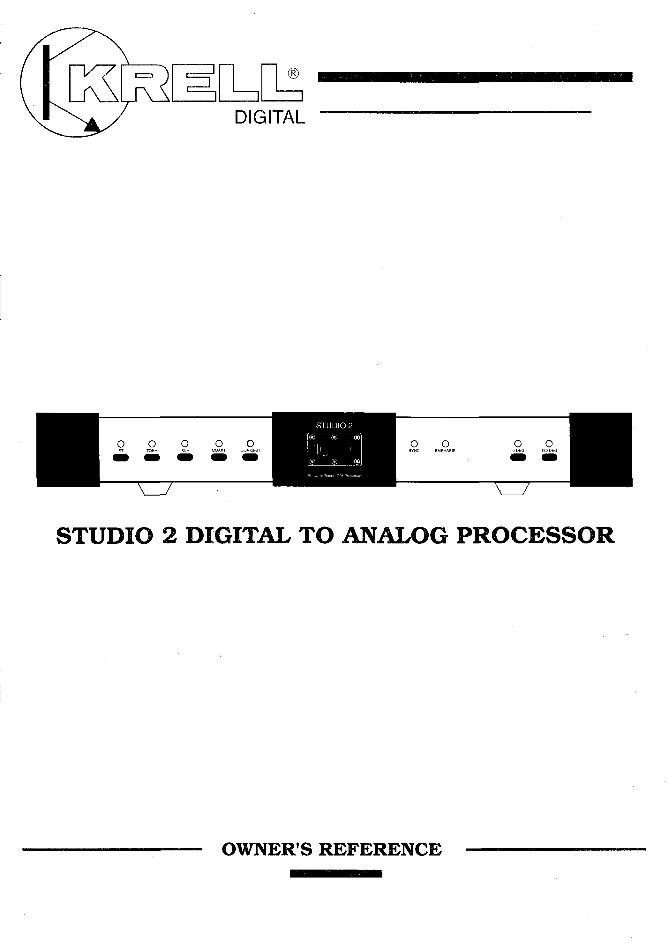
STUDIO 2 DIGITAL TO ANALOG PROCESSOR - Krell … · INTRODUCTION Thank you for your purchase of the...
20
STUDIO 2 O O 0 0 0 0 0 0 0 STUDIO 2 DIGITAL TO ANALOG PROCESSOR OWNER’S REFERENCE
Transcript of STUDIO 2 DIGITAL TO ANALOG PROCESSOR - Krell … · INTRODUCTION Thank you for your purchase of the...
STUDIO 2
O O 0 0 0 0 0 0 0
STUDIO 2 DIGITAL TO ANALOG PROCESSOR
OWNER’S REFERENCE
INTRODUCTION
Thank you for your purchase of the Krell STUDIO 2 Digital-to-Analog Processor and welcome to the Krell family of audiocomponents. Krell is dedicated to the development of technologi-cally advanced components for the reproduction of digitallyrecorded music. The STUDIO 2 continues the Krell tradition ofuncompromising performance through leading-edge technology.
To obtain the best performance from your STUDIO 2 Processor,careful attention should be paid to its placement, installation andoperation. A thorough understanding of these details will helpinsure satisfactory operation and long life for the STUDIO 2 andrelated system components.
This Owner’s Reference is divided into several sections whichdescribe the features and functions of the STUDIO 2. A Questionand Answer section is included to provide answers to commonquestions. Shouldyou have any questions or suggestions, pleasefeel free to contact your authorized dealer or the KRELL staff forassistance.
In the unlikely event that your STUDIO 2 should require service,you will be pleased to know that it is backed by a comprehensiveCustomer Satisfaction policy and one of the most advancedservice facilities in the industry. For detailed information on theterms and conditions of service, please consult the Warranty andService section of this Reference, Warranty Registration Card, orauthorized KRELL Dealer/Distributor.
PAGE 2

....... TABL~ OF CONTENTS
4 UNPACKING INSTRUCTIONS
5 PLACEMENT
6 AC POWER CONSIDERATIONS
7 INPUT AND OUTPUT CONNECTIONS
i i PROCESSOR OPERATION
13 OPERATING INSTRUCTIONS
15 QUESTIONS AND ANSWERS
18 SPECIFICATIONS
19 WARRANTY AND SERVICE INFORMATION
PAGE 3
UNPACKING
UNPACKING INSTRUCTIONS
1. Open the box and remove the top layer of foam. The followingitems will now be visible:
STUDIO 2 D/A ProcessorAC power cordPacket containing the Owner’s Reference and WarrantyCard
NOTE: If any of these items are not included, please contact yourauthorized dealer immediately for assistance.
2. Carefully remove the STUDIO 2 from the box. Remove theprotective plastic wrap from the Processor.
NOTE: Save all packing materials. If you must ship yourSTUDIO 2 in the future, repack the unit in its original packagingto prevent transit damage.
PAGE
PLACEMENT
PLACEMENT
Before you install the STUDIO 2 into your system, we recommendthat you follow these guidelines in choosing the location. This willfacilitate a clean, trouble-free installation.
1. Although well shielded, the STUDIO 2 should not be placed inclose proximity to hum-sensitive components (i.e. preamps,turntables, tuners, etc.) that can create interference and inducehum.
2. As with any high quality component, ensure that the ventopenings in the chassis are free from obstruction, allowing theProcessor to dissipate heat created by its power supply and ClassA output stage. Place the unit on a clean, level surface away fromexcessive dirt or moisture. Make sure the STUDIO 2 has at least2 inches of clearance on either side and 2-3 inches of space at thetop. Components that are heat sensitive should not sit directlyabove the unit.
3. The STUDIO 2 does not require additional mass coupling orisolation. You may experiment with feet or cones as long as theydo not permanently affix to the chassis. Any unauthorizedmodifications to the electronics or chassis will void the warranty.
PAGE 5

AC POWER
AC POWER CONSIDERATIONS
NOTE: While the STUDIO 2 has superb regulation and does notrequire a dedicated AC circuit, we strongly advise against anyconnections through extension cords or multiple AC adaptors.High quality 15 amp grounded AC strips are acceptable. Highquality AC line conditioners or filters can be utilized if they aregrounded and meet or exceed the unit’s power supply rating of150VA.
CAUTION: Do not remove or bypass the ground pin on the endof the AC cord. This may cause RFI (radio frequency interference)to be induced into your playback system.
PAGE 6
CONNECTIONS
INPUT AND OUTPUT CONNECTIONS
CAUTION: When making connections to this component or anyother, make sure the power amplifier is OFF and the preamplifieris in the MUTE or STANDBY mode.
1. Connect the power cord to the back of the STUDIO 2 and plugthe unit into the wall AC receptacle.
2. Connect the STUDIO 2 analog output to the line level input ofyour preamplifier.
The STUDIO 2 is equipped with two analog output configurations:Single-ended via RCA connectors and balanced via XLR connec-tors. If your preamplifier has high level balanced inputs, werecommend the balanced outputs of the Processor be used. Thereare considerable sonic benefits associated with the use of balancedinterconnection.
The XLR pin configuration is described below.
Pin 1Pin 2Pin 3
GroundNon-inverting (0°)
Inverting ( 180°)
NOTE: The two outputs can be used to simultaneously feeddifferent systems.
NOTE: If you decide to use the single-ended analog outputs, thetype of interconnect cable should be chosen carefully. Highquality shielded cable is suggested.
PAGE 7
CONNECTIONS
3. The Left and Right channel RCA outputs are labeled on theback panel. The balanced outputs are not labeled. The balancedconnector closest to the Left RCA output is for the left channeloutput and the connector closest to the RCA right output is theright balanced output. Care should be taken to insure that thechannel orientation between the Processor and the high levelinputs of your preamplifier is maintained.
4. Connect the digital output of your CD transport and otherdigital sources to the inputs of the STUDIO 2. If you are usingmultiple digital sources, take note of where each input andcorresponding switch setting is located.
The STUDIO 2 is equipped with the following inputs: two coaxial,one AT&T wide bandwidth fiber optic, standard TOSH fiber optic,and one AES/EBU. All inputs can accept a signal from any digitalsource such as Compact Disc players, Laser Disc players, DATsor satellite receivers. When a powered digital source is introducedto an input and that input is selected with the specific Inputswitch, the corresponding signal LED will illuminate. When thesource and the Processor have locked the SYNC indicator LEDwill illuminate.
The STUDIO 2 has a provision to add an additional AT&T input.The second AT&T input will replace the Coax 2 space on the backpanel and is selected by the COAX2/ST input switch. For furtherinformation contact KRELL.
NOTE: If the digital source is ON and the signal LED does notilluminate, check to make sure the digital interconnect cable issecure at both ends or is not in need of repair.
PAGE 8
CONNECTIONS
5. Once you have completed the necessary input and outputconnections, select the input of your choice. For each inputselected, the corresponding LED will illuminate. When a powereddigital input source and the Processor have linked, the SYNC LEDwill illuminate.
DIGITAL SOURCE TO D/A PROCESSOR INTERLINK CONSID~,ERATIONS
Care should be taken in selecting the type of cable used to link thedigital source to your Processor. We suggest the AT&T wide-bandwidth fiber optic cable be used. The AT&T format has abandwidth of approximately 50 MegaBit. This allows accuratetransmission of the digital bit stream without data corruptionand proves to be sonically superior. If the AT&T format is notavailable, a high quality quartz fiber optic cable (TOSH format)can work well. Using a fiber optic interconnect reduces groundloop problems often associated with quality audio systems.
If coaxial cable is used, it should be non-capacitive and have abandwidth in excess of 10MHz to prevent drop-out errors. Forbest results with coaxial cable we recommend the AES/EBUbalanced format. The AES/EBU format is a + 5 volt balanceddigital transmission. Because of the high voltage balanced for-mat, this system allows for accurate data transmission and hasgreat sonic advantages over standard single-ended coaxial orTosh fiber optic terminations. The AES/EBU coaxial cable musthave two conductors and a shield for balanced termination.
PAGE 9
CONNECTIONS
How to connect AT&T cables:
a. Remove the plastic cover from the outside of the AT&Ttransmitter (located on Transport) and receiver (located on Pro-eessor).
b. Locate the slot on the top of the AT&T receptacle.
e. Locate the key on the top of the AT&T cable.
d. Remove the plastic cap from both ends of the fiber optic cable.
e. Slide the cable connector into the AT&T receptacle with the keysliding into the designated slot.
f. Gently push the connector into place, depressing the internalspring, and twist the outer collar clockwise to secure the con-nection.
PAGE 10
OPERATION
INPUT SELECT SWITCHING
The STUDIO 2 has multiple digital inputs. Each input has its owninput switch and direct path to the digital Processor. When aninput is selected, the corresponding LED will illuminate.
AT&TTOSHXLRCOAX1COAX 2/ST
AT&T fiber optic inputToshiba fiber optic inputBalanced AES/EBU digital inputCoaxial inputCoaxial input or Optional-2nd AT&T ST input
SYNC INDICATOR
When the input signal locks with the Processor, the SYNC LEDwill illuminate. The input frequency is automatically selected bythe Processor. As an example, if you select the AT&T input froma CD transport, the 44.1 KHz frequency will automatically beselected and the SYNC LED will illuminate. The STUDIO 2 willaccept and automatically adjust to 38.0 KHz, 44.1 KHz, and 48.0KHz input frequency signals.
PAGE 11
OPERATION
0° and 180 ° PHASE SWITCHING
The absolute output phase of the STUDIO 2 can be changed. Insome recordings the master tape was recorded out of phase,creating unusually poor sounding recordings. The STUDIO 2 canshift the absolute output phase 180° to correct for this anomaly.To change the phase from 0° to 180°, press the 180 DEG button.To change back to normal phase, press the 0 DEG button.Utilizing the Phase Switching can, in some instances, restore lifeto a previously dull sounding recording.
EMPHASIS LED
Emphasis is a recording technique that accentuates the trebleregion of recorded music. Discs and/or Tracks that were recordedwith Pre-emphasis will cause the Emphasis LED to illuminate.When the Emphasis LED is lit, the appropriate complementarycircuitry (De-emphasis) is activated to provide a fiat outputresponse.
PAGE 12
OPERATION
OPERATING INSTRUCTIONS
1. Select an input with the Input switch. Notice the Signal LEDwill illuminate when the digital source is turned on and has linkedwith the Processor. Once this link is complete, the Processor isready to pass a signal.
2. Be sure that your preamplifier volume controlcompletely to the OFF (lowest volume) position.
is turned
3. Turn ON your components, remembering that the last compo-nent to be energized should be your amplifier. The amplifiershould only be turned ON after all other components in thesystem have been on for at least two minutes. This will insurethat no large pulse will be created when the amplifier is turned on.
4. Switch the source selector of your preamp to the positioncorrelating to your chosen input connection for the STUDIO 2.
5. You may now start playing your digital source, DAT, CD orsatellite.
6. Slowly turn the volume control up to the lowest level you canhear. Check to see that both channels are working correctlybefore advancing the volume.
PAGE 13
OPERATION ’ " ’"
NOTE: While your STUDIO 2 will perform beautifully from themoment you turn it on, it requires a minimum warm-up periodof 8 hours before it begins to show its strongest sonic qualities.It will continue to improve over time. Discrete components areutilized in the analog output stage and the warm-up period allowsthem to reach thermal equilibrium.
Your installation is now complete. Should you have any furtherquestions which are not covered in the remainder of this Refer-ence, contact your authorized Krell dealer. We wish you manyhours of listening fulfillment.
PAGE 14
QUESTIONS AND ANSWERS
Q. My CD player has both fiber optic and coaxial outputs. Whichone should I use?
A. Given a choice, we prefer the AT&T optical link due to its abilityto completely isolate the grounds between the digital sourcecomponent and the Processor. This minimizes the possibility ofground loops in the digital components. The AT&T format alsohas the added benefit of substantially higher bandwidth thancoax or the standard fiber optic interface. If a coax cable must beused, we suggest the AES/EBU balanced format. This inter-connection utilizes a + 5v digital format and the additionalbenefit of balanced termination.
Q o Will I damage my STUDIO 2 if I leave the power "ON" all thetime?
A. No. The Class A discrete analog circuits perform more consis-tently once they reach thermal equilibrium. This Processor hasbeen designed to be left On at all times. The STUDIO 2 draws lessthan 30 watts out of the AC mains socket.
NOTE: For the protection of your Processor, we recommenddisconnecting the AC cord from the wall outlet before anyelectrical storms or if you plan on being away from home forprolonged periods of time.
PAGE 15
QUESTIONS AND ANSWERS
Q. Do I have to switch the Sampling Frequency when I go betweenmy CD and DAT?
A. No. Your STUDIO 2 automatically senses the input frequencyand does all necessary switching.
Q. I am not getting any sound through the Processor. What couldbe wrong?
A. Most likely there has been a simple mistake in installation.Check all connections IN and OUT of the Processor. Is the digitalsource component powered? Check all power connections. Haveyou selected the correct source on the STUDIO 2 and preamp?Check the front panel LED’s for power supply stability. If you stillhave no sound, turn off the power and contact your dealer.
Q. I have some very fine audiophile interconnect.cable which hassuperior sonic characteristics. Can I use this for my coaxial digitalinput?
A. You may experiment with any high quality cable. Do note thatmost audio interconnect cable is not designed to carry the ultra-high frequency information of the digital bit stream.
NOTE: For the STUDIO 2, we recommend non-capacitive coaxialcable which has a bandwidth in excess of 10MHz and excellentshielding properties.
PAGE 16
QUESTIONS AND ANSWERS
Q. While listening to my STUDIO 2 I experience occasionalperiods of silence through my speakers. Is my Processor malfunc-tioning?
A. Drop outs are caused by two primary reasons. First, drop outscan be caused by data corruption. Corruption in the data may bedue to a poor input connection, damaged or dirty source material,or interconnects which do not have wide enough bandwidth. Thesecond item that causes the Processor to reset is the presence ofa transient spike on the incoming AC power line. The Processoris resetting all of its digital processing circuits so that it can beassured that all are properly synchronized. Try changing yoursource material and check your connections. If these are not thecause, speak with your dealer about obtaining different cabling.If you are using fiber optics, and source material and connectionsare not the problem, speak with your authorized dealer.
Q. Since I installed the Processor in my system I have a low levelhum that increases as I turn up the volume. There was no humin my system until I added the Processor. Is the Processormalfunctioning?
Ao The fact that there was no hum in your system until you addedthe Processor indicates that you have a ground-loop problem.Often changing the interconnect to a fiber optic cable willeliminate this problem. The way the digital Processor and digitalsource are connected to the AC mains often can be the cause ofgrounding problems. Check for loose interconnect cables and orbad electrical connections. Consult your dealer or Krell forindividual system suggestions if this hum persists.
PAGE 17
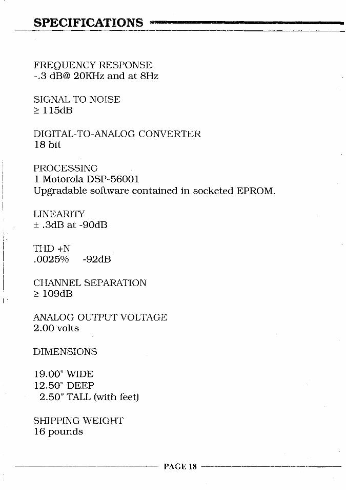
SPECIFICATIONS
FREQUENCY RESPONSE-.3 dB@ 20KHz and at 8Hz
SIGNAL TO NOISE> 115dB
DIGITAL-TO-ANALOG CONVERTER18 bit
PROCESSING1 Motorola DSP-56001Upgradable software contained in socketed EPROM.
LINEAt~TY+ .3dB at -90dB
THD +N.0025% -92dB
CHANNEL SEPARATION>_ 109dB
ANALOG OUTPUT VOLTAGE2.00 volts
DIMENSIONS
19.00" WIDE12.50" DEEP2.50" TALL (with feet)
SHIPPING WEIGHT16 pounds
PAGE 18

WARRANTY AND SERVICE
WARRANTY AND SERVICE INFORMATION
There are no user-serviceable parts inside the STUDIO 2. TheSTUDIO 2 has a limited warranty of five years parts and labor.Return freight is included in the warranty. The warranty periodbegins on the date of purchase and is activated with the returnof the enclosed Warranty Card and a copy of the Sales receipt.Please return the Warranty Card immediately after successfulinstallation and operation are completed.
The warranty for Krell products is valid only in the country towhich they were originally shipped and at the factory. If you thinkthere are problems with your unit, please contact your dealer,distributor or the factory immediately.
The operating voltage of this unit is determined by the factory andcan only be changed by an authorized KRELL distributor or theKRELL factory. Any unauthorized voltage conversion will void thewarranty. Should the operating voltage of your STUDIO 2 requirechanging, contact KRELL Industries.
Please do not return any unit to KRELL for repair without firstcalling to discuss the problem and to obtain a Return Authoriza-tion number. Freight to the factory or distributor is your re-sponsibility. Return freight to you will be paid by the factory ordistributor. Any unauthorized disassembly, updates or modifica-tions performed to the unit will void the warranty.
PAGE 19

KRELL35 Higgins Drive Milford CT 06460
SALES (203) 874-3139 FAX (203) 878-8373© 1993 KRELL DIGITAL
(STUDIO29303)