INSTRUCTION MANUAL VARTA pulse - AC Solar Warehouse · Legal notice Translation of the original...
158
VARTA Storage GmbH INSTRUCTION MANUAL VARTA pulse
Transcript of INSTRUCTION MANUAL VARTA pulse - AC Solar Warehouse · Legal notice Translation of the original...

VARTA Storage GmbH
INSTRUCTION MANUAL
VARTA pulse


Congratulations!
You have opted for an energy storage system from VARTA Storage GmbH! We are pleased that in doing so, you chose a durable system for which we considered quality paramount. Please read through these instructions carefully. They describe how to operate and use the battery.
Have fun storing power!
Guidance for the qualified electrician
The first part of this manual contains general information on how to use the VARTA pulse energy storage system.
Further information can be found in the “Installation”, “Operation in the password-protected area” and “Maintenance” sections.

Legal notice
Translation of the original instruction manual for VARTA pulse.
VARTA Storage GmbH Nürnberger Strasse 65 86720 Nördlingen Germany
www.varta-storage.com
Tel.: 0049 9081 240 86 60 [email protected]
Technical service: If you need help troubleshooting or installing your device, please contact your local VARTA storage's technical support team stated on our homepage https://www.varta-storage.com/kontakt/.
Document number: OM 850853
Updated: 8/2018
Version: 03

I
Contents
General ........................................................................................... 3
1. Information about this manual ..................................................... 3
1.1. Explanation of symbols .......................................................... 3
1.1.1 Safety instructions ............................................................. 3
1.1.2 Warning levels ................................................................... 4
1.1.3 General safety signs .......................................................... 5
1.1.4 Warning signs .................................................................... 6
2. Safety........................................................................................... 7
2.2. General information on safety ................................................ 7
2.3. Intended use .......................................................................... 8
2.4. Requirements regarding qualified electricians ....................... 9
2.5. General hazard sources....................................................... 10
2.5.1 Danger of electrical voltage ............................................. 10
2.5.2 Danger from water ........................................................... 11
2.5.3 Danger from oxidising and corrosive substances ........... 12
2.5.4 Danger from heat ............................................................ 13
2.5.5 Danger from misbehaviour .............................................. 14
2.6. Safety devices ...................................................................... 15
3. Function, scope of delivery and technical parameters .............. 16
3.1. Function ............................................................................... 16
3.2. Derating................................................................................ 17
3.3. Scope of delivery ................................................................. 18
3.4. Front view VARTA pulse ...................................................... 19
3.5. System overview .................................................................. 20
3.6. Rating plate .......................................................................... 21
3.7. Technical parameters .......................................................... 22

II
Operation ...................................................................................... 26
4. Switching on and off, web interface ........................................... 26
4.1. Switching on and off ............................................................. 27
4.2. LED ring indications .............................................................. 28
4.3. Web interface ........................................................................ 29
4.3.1 Access to the web interface ............................................. 29
4.3.2 Information on the welcome page (Home) ....................... 30
4.4. External relays (optional) ...................................................... 31
4.5. Portal (optional) .................................................................... 32
5. Maintenance and cleaning ......................................................... 33
5.1. Maintenance work ................................................................. 33
5.2. Cleaning ................................................................................ 34
6. Malfunction/event of damage ..................................................... 35
6.1. Malfunction indicators ........................................................... 36
6.1.1 Malfunction indicators of the LED ring ............................. 36
6.1.2 Malfunction indicators on the web interface ..................... 36
6.2. Behaviour in the event of damage ........................................ 36
Installation .................................................................................... 38
7. Transport and storage ................................................................ 38
7.1. Transport .............................................................................. 38
7.2. Transportation regulations and safety instructions ............... 39
7.3. Packaging/transport control .................................................. 41
7.4. Storage ................................................................................. 42
8. Assembly and installation ........................................................... 43
8.1. Check the components ......................................................... 43
8.2. Requirements for the installation location ............................ 44

III
8.3. Installation location .............................................................. 45
8.3.1 Dimensions and features................................................. 45
8.3.2 Environmental conditions ................................................ 46
8.3.3 Impermissible locations and environmental conditions ... 47
8.4. Warranty............................................................................... 47
8.5. Warranty registration ............................................................ 50
8.5.1 Warranty registration by the installation engineer ........... 50
8.5.2 Warranty registration by the customer ............................ 55
8.6. Preparation of the electrical connection ............................... 59
8.6.1 Connections to the distributor box ................................... 61
8.6.2 Preparation of the AC port for the building grid ............... 61
8.6.3 VARTA Split Core current sensor ................................... 63
8.7. Preparation of assembly ...................................................... 68
8.8. Installing and connecting the energy storage system .......... 69
8.9. Battery module assembly..................................................... 72
8.10. Inspecting the battery module ............................................ 73
8.11. Behaviour in the event of damage ..................................... 74
8.12. Installing and connecting the battery module .................... 75
8.12.1 Installing the battery module ......................................... 76
8.12.2 Closing the energy storage system ............................... 79
8.13. Initial commissioning .......................................................... 81
8.13.1 Switching on .................................................................. 81
8.13.2 Password entry .............................................................. 83
8.13.3 Entering the serial numbers of the battery module ....... 84
8.13.4 Portal connection ........................................................... 86
8.13.5 Setting the grid parameters for GS protection............... 87
8.13.6 Reboot ........................................................................... 89
8.13.7 Checks on the welcome page ....................................... 90

IV
8.13.8 Checks on the "System" page ....................................... 91
8.13.9 Exiting the password-protected area ............................. 92
8.14. Quick Install ........................................................................ 93
9. Operation in the password-protected area ................................. 95
9.1. The password-protected area ............................................... 95
9.1.1 Access to the web interface - password entry ................. 95
9.2. System .................................................................................. 96
9.3. Version .................................................................................. 96
9.4. Settings ................................................................................. 97
9.4.1 Basic settings ................................................................... 98
9.4.2 Network ............................................................................ 99
9.4.3 Service settings .............................................................. 100
9.4.4 Grid parameters for GS protection ................................. 101
9.4.5 Reactive power compensation ....................................... 103
9.5. Power limitation .................................................................. 110
9.6. Logging out ......................................................................... 110
Maintenance ................................................................................ 111
10. Maintenance basics ............................................................... 111
10.1. Safety instructions ............................................................ 111
10.2. Scope of maintenance work ............................................. 113
11. Service and repair work ......................................................... 114
11.1. Inspecting the energy storage system from outside ......... 114
11.2. Checking the system parameters (Service) ..................... 114
11.2.1 Checking the online status ........................................... 114
11.2.2 Error lists ...................................................................... 115
11.2.3 Checking the software version ..................................... 116
11.2.4 Software update ........................................................... 117

V
11.2.5 Air filter change: Resetting the time ............................ 117
11.2.6 Checking the fan ......................................................... 118
11.3. Checking the system parameters .................................... 119
11.3.1 Checking the current sensor values ............................ 119
11.3.2 Checking the battery inverter ...................................... 120
11.3.3 Checking the battery module....................................... 121
11.4. Service and maintenance: Housing interior ..................... 122
11.4.1 Opening the energy storage system ........................... 124
11.4.2 Installing the battery inverter ....................................... 127
11.4.3 Removing and installing the battery module ............... 128
11.4.4 Removing the battery module ..................................... 129
11.4.5 Installing the battery module ....................................... 131
11.4.6 Cleaning the fan and air filter ...................................... 131
11.4.7 Exchanging SD Card ................................................... 132
11.5. Completion of service and repair work ............................ 134
11.5.1 Checking the operating state ...................................... 135
11.5.2 Cleaning ...................................................................... 137
12. Malfunctions .......................................................................... 138
12.1. Malfunction indicators of the LED ring ............................. 138
12.2. Malfunction indicators on the web interface .................... 138
13. Disassembly and disposal ..................................................... 139
13.1. Planning disassembly ...................................................... 139
13.2. Disassembling .................................................................. 140
13.3. Disposal ........................................................................... 141
14. Relocation .............................................................................. 142
14.4. Planning a relocation ....................................................... 142
14.5. Relocating ........................................................................ 143

VI
Index
C
CTRL EMS State Energy-Management-System ......................................... 120
CTRL ENS State Network and Plant Protection ......................................... 120
CTRL WR State inverter ............................................................................ 120
D
DCEN DCDC-Converter ................................................................ 96, 116
E
EM E-Meter (intern) .................................................................. 96, 116
EMS Energy-Management-System ....................................96, 115, 116
EMS-Mode Energy-Management-System-Mode ........................................ 120
ENS Network and Plant Protection ................................................... 115
F
F Grid Power frequency ...................................................................... 120
Fan State of fan ............................................................................... 120
FGRID_MAX Maximum grid frequency .......................................................... 102
FGRID_MIN Minimum grid frequency ........................................................... 102

VII
I
I Grid Current measured at Grid-Sensor ............................. 92, 119, 120
I PV Current measured at PV-Sensor ............................... 92, 119, 120
IBatt Battery-Current ........................................................................ 121
P
P Grid Power at grid connection point ................................................ 120
P Inv Power at inverter output .......................................................... 120
P Request Requested Power .................................................................... 120
PIst Actual Power ........................................................................... 121
PSoll
Target Power ........................................................................... 121
R
RCMU Residual Current ...................................................................... 120
S
Sensor Phase
Connected Phase ...................................................... 92, 119, 120 SerNr
Serial Number .......................................................................... 121 SoC
State of Charge ............................................................... 120, 121

VIII
T
TBoard Temperature Mainboard ........................................................... 121
TempEMS Environment Temperature ....................................................... 120
TempHB Temperature H-Bridge.............................................................. 120
THT Temperature high step-down Converter .................................. 121
TTR Temperature Transformer ........................................................ 121
U
U Inv Voltage at inverter output ...........................................92, 119, 120
U N -> PE Voltage between N and PE wire .............................................. 120
UBatt
Battery-Voltage ......................................................................... 121 UGRID_MAX
Maximum grid voltage .............................................................. 102 UGRID_MAX10
Maximum grid voltage for 10 minutes ...................................... 102 UGRID_MIN
Minimum grid voltage ............................................................... 102 UVcc
Internal Supply Voltage ............................................................ 121 UZwk
Voltage of Intermediate-Circuit ......................................... 120, 121
W
WR Inverter .......................................................................96, 115, 116

1
About this manual
Please read this instruction manual before beginning any kind of work. It contains important information, in order to ensure trouble-free functioning of the VARTA pulse energy storage system.
The manual is structured in a way, so all work can be carried out by a qualified electrician certified by VARTA Storage.
Storage of the manual
The instruction manual should be kept in close proximity to the VARTA pulse and must be permanently available to all individuals involved in working on the energy storage system. If the owner changes, the instruction manual has to be handed over.
Target groups
This manual is intended for different target groups:
End customers
Qualified electrician who is responsible for installation, commissioning and maintenance.
Scope
This manual is part of the system and corresponds to the state-of-the-art at the time of publication. It is intended for the product VARTA pulse in the expansion stages pulse 3 and pulse 6.
i Please keep in mind that this instruction manual
also refers to optional components, which are not
included in the scope of delivery as standard.
These parts or components are designated
"optional" in this manual. Just skip these parts of
the manual if your energy storage is not
equipped with them.

2
Limitation of liability
VARTA Storage GmbH accepts no liability for personal injuries, material damage, damages at the product, as well as consequential damages arising from non-observance of this manual, improper use of the product, during repairs, opening of the storage cabinet and other activities carried out by unqualified electricians or electricians who were not certified by VARTA Storage. This limitation of liability also applies to the use of non-approved spare parts, as well as non-observance of the stated maintenance intervals.
It is prohibited to carry out unauthorised modifications or technical changes at the product.
© VARTA Storage GmbH 2018
Special attention required
ATTENTION
Energy storage system switched off!
Potential damage to the battery module due to deep discharge.
The energy storage system may be switched off temporarily only for maintenance purposes.
3
Ge
ne
ral
Op
era
tio
n
Insta
llation
Op
era
tio
n (
Serv
ice
) M
ain
ten
ance
General
1. Information about this manual
1.1. Explanation of symbols
This instruction manual uses the following types of safety instructions and tips:
i Indicates tips for handling the device.
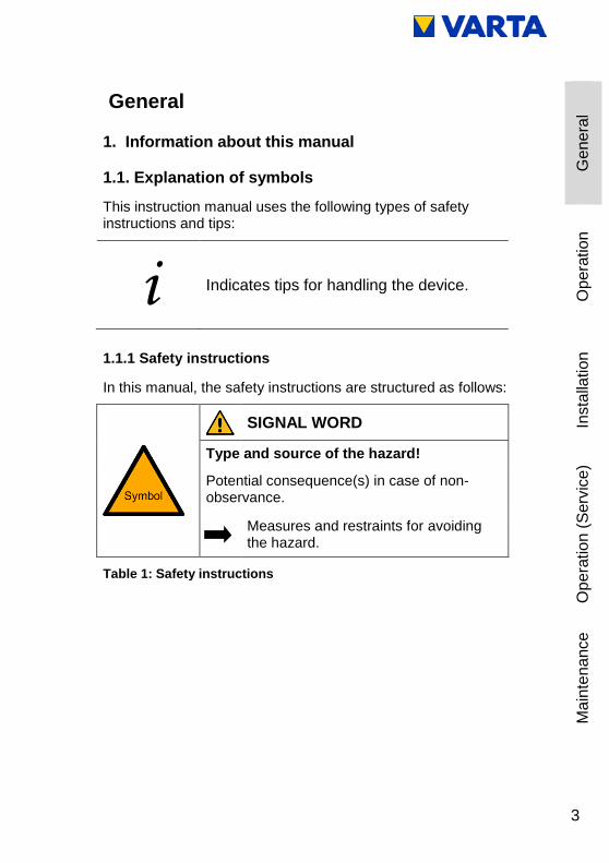
1.1.1 Safety instructions
In this manual, the safety instructions are structured as follows:
SIGNAL WORD
Type and source of the hazard!
Potential consequence(s) in case of non-observance.
Measures and restraints for avoiding the hazard.
Table 1: Safety instructions
4
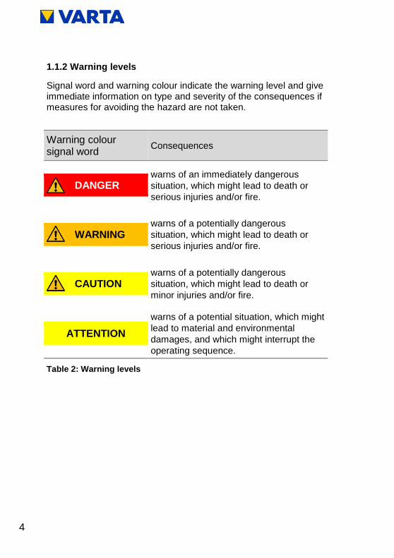
1.1.2 Warning levels
Signal word and warning colour indicate the warning level and give immediate information on type and severity of the consequences if measures for avoiding the hazard are not taken.
Warning colour signal word
Consequences
warns of an immediately dangerous
situation, which might lead to death or
serious injuries and/or fire.
DANGER
warns of a potentially dangerous
situation, which might lead to death or
serious injuries and/or fire. WARNING
warns of a potentially dangerous
situation, which might lead to death or
minor injuries and/or fire. CAUTION
warns of a potential situation, which might
lead to material and environmental
damages, and which might interrupt the
operating sequence.
ATTENTION
Table 2: Warning levels
5
Ge
ne
ral
Op
era
tio
n
Insta
llation
Op
era
tio
n (
Serv
ice
) M
ain
ten
ance
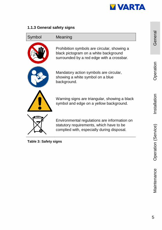
1.1.3 General safety signs
Symbol Meaning
Prohibition symbols are circular, showing a
black pictogram on a white background
surrounded by a red edge with a crossbar.
Mandatory action symbols are circular,
showing a white symbol on a blue
background.
Warning signs are triangular, showing a black
symbol and edge on a yellow background.
Environmental regulations are information on
statutory requirements, which have to be
complied with, especially during disposal.
Table 3: Safety signs

6
1.1.4 Warning signs
General warning sign
Warning of electrical voltage
Warning of oxidising substances
Warning of hand injuries
Warning of cut injuries
Warning of hazards due to batteries
Warning of non-observance of the discharge
time:
3 minutes!
Table 4: Warning signs

7
Ge
ne
ral
Op
era
tio
n
Insta
llation
Op
era
tio
n (
Serv
ice
) M
ain
ten
ance
2. Safety
2.2. General information on safety
Any person in charge of carrying out work on the system must have read and understood this manual.
WARNING
Non-observance of the safety instructions!
Improper use can lead to fatal injuries.
Prior to use, ensure that all protective
devices are functioning.
By observing the safety instructions and complying with the instructed health and safety measures, the risk will be limited.
Read the instruction manual.
This manual cannot describe every conceivable situation, therefore the currently applicable standards as well as the appropriate regulations for industrial safety and health protection always have priority.
Furthermore, the use of the energy storage system is associated with residual risks under the following circumstances:
Installation and maintenance work is not performed correctly.
Installation and maintenance work is performed by personnel who have not been trained and not been instructed.
The safety instructions provided in this manual are not observed.

8
All safety instructions have to be strictly followed, the observance is for your safety. The device must not be modified in any way.
2.3. Intended use
VARTA pulse as well as the components thereof, is built to state-of-the-art technology and to product-specific standards. This product is designed for storing electricity from renewable energy generating plants, such as photovoltaic systems or other energy sources such as CHPs. Any other use must be agreed in consultation with the manufacturer and the local energy supplier. The energy storage system may be operated only when hanging on a wall. The device is not designed to be used in three-phase combinations.
WARNING
Possible mortal danger due to wrong use!
Possible mortal danger.
The device accommodates parts
carrying hazardous voltages. Contact
with these parts can be fatal.
Any usage beyond or other than the
intended use of the energy storage
system or individual parts of it might
lead to life threatening situations.
Do not use VARTA pulse:
for mobile use at land, water or air.
for use at medical devices.
e.g. lying or standing on the floor or a table.

9
Ge
ne
ral
Op
era
tio
n
Insta
llation
Op
era
tio
n (
Serv
ice
) M
ain
ten
ance
2.4. Requirements regarding qualified electricians
WARNING
Insufficient qualification of the electrician!
Personal injuries and material damage.
Work on the VARTA pulse system (e.g.
installation and maintenance work) may
only be carried out by qualified
electricians who are certified by VARTA
Storage!
i The “Installation”, “Operation in the password-
protected area” and “Maintenance” sections
contain further information for qualified
electricians.

10
2.5. General hazard sources
If the following instructions for handling the device are not observed, this might lead to personal injury or material damage at the device, for which VARTA Storage will accept no liability.
2.5.1 Danger of electrical voltage
DANGER
Contact with electrical voltage!
Risk of fatal injury from electric shock.
Keep the energy storage system
always closed.
Pay attention to damage of the
electrical equipment! Eliminate defects
immediately.
Only the electrician is allowed to open
the energy storage system when it is
switched off.
Respect the waiting times.

11
Ge
ne
ral
Op
era
tio
n
Insta
llation
Op
era
tio
n (
Serv
ice
) M
ain
ten
ance
2.5.2 Danger from water
WARNING
Entry of water into electrical systems!
Possible mortal danger and material damage.
Do not use water for cleaning the
energy storage system.
Never put down containers with fluids
(beverage containers and the like) on
electrical systems.
The relative humidity at the installation
location must not exceed 80 %.
Do not put wet devices or components
into operation.
Do not put devices or components that
have become wet into operation.
Contact VARTA Storage.

12
2.5.3 Danger from oxidising and corrosive substances
WARNING
Storage and use of oxidising and corrosive substances!
Increases the risk of fire and the risk of
electric shocks.
Store the above mentioned substances
only at places that are intended for
them.
Do not clean the system with agents
containing acid, lye or solvents.

13
Ge
ne
ral
Op
era
tio
n
Insta
llation
Op
era
tio
n (
Serv
ice
) M
ain
ten
ance
2.5.4 Danger from heat
ATTENTION
Insufficient ventilation of the system!
Overheating of the system possible.
Keep the ventilation openings clear.
Ensure sufficient ventilation.
ATTENTION
Heat input due to direct sunlight or devices
emitting heat!
Overheating and damage of the system
possible!
Protect the system against direct
sunlight.
Do not use fan heaters or the like near
the system.

14
2.5.5 Danger from misbehaviour
ATTENTION
Energy storage system switched off!
Potential damage to the battery module due
to deep discharge.
The energy storage system may be
switched off temporarily only for
maintenance purposes.
ATTENTION
Objects on the system!
Risk of injury due to falling objects, and the
system might be damaged.
Do not put any objects on the energy
storage system.
ATTENTION
Blocked access!
In the event of damage, the system cannot be
switched off.
The access to the energy storage
system must always be ensured.
Access to the associated circuit-
breaker must be assured at all times

15
Ge
ne
ral
Op
era
tio
n
Insta
llation
Op
era
tio
n (
Serv
ice
) M
ain
ten
ance
2.6. Safety devices
WARNING
Defective safety devices!
Possible mortal danger.
Safety devices must not be damaged,
modified, removed, or
decommissioned.
The proper functioning of the safety
devices must be tested by qualified
electricians who are certified by VARTA
Storage after completion of installation
and commissioning.
The VARTA pulse energy storage system has multiple safety devices. Including grid and system protection to country-specific standards, e.g. VDE-AR-N 4105, closed electrical operating area, overtemperature cutout and a mechanical shutoff mechanism. This switches off the unit if an attempt is made to open the housing before the energy storage system has been de-energised.
Furthermore it is recommended to install a smoke detector at the installation location of the VARTA pulse.

16
3. Function, scope of delivery and technical parameters
3.1. Function
The VARTA pulse energy storage system is intended for use on a AC household electrical system and is capable of being connected to a separate grid-coupled photovoltaic system. This must be a generating unit which supplies to surplus rather than to full feed. There is also provision for storing renewable energy, for example from small wind turbines or other energy sources such as CHPs.
The energy stored system is intended to increase the in-house consumption percentage and the economy of a photovoltaic system. If the photovoltaic system generates more electricity than immediately needed, it can be stored temporarily in the energy storage system. The electricity will be fed into the building grid, as soon as the consumption rises again above the electricity generated by the photovoltaic system.
The energy storage system is integrated into the building grid as an AC connection and operates independently of the photovoltaic system. A current sensor controls the charge and discharge processes of the energy storage system. It is mounted in the fuse box, directly behind the consumption/feed-in meter, and measures all incoming and outgoing currents.
If the current sensor measures outgoing currents in case of available free charge capacity of the energy storage system, it will be charged. During the process, the battery inverter inside the energy storage system converts AC to DC and charges the battery module. If the maximum charge capacity is reached, or the solar electricity exceeds the maximum charging current, the surplus solar electricity is fed into the public grid. If the photovoltaic system is not able to cover the current electricity demand inside the building, the current sensor measures incoming currents. As a result, the energy storage system gives output into the building grid, in order to minimise the external electricity consumption and the associated costs.
Before the VARTA energy storage system is installed, the appropriate energy provider/grid operator must be asked whether it is necessary to register the system.

17
Ge
ne
ral
Op
era
tio
n
Insta
llation
Op
era
tio
n (
Serv
ice
) M
ain
ten
ance
3.2. Derating
Power reduction (derating) entails the temporary curtailment in the maximum power of the battery inverter in order to prevent excessive heating of components.
Frequent temperature-related derating can have the following causes:
The ambient temperature exceeds +30 °C.
The system cannot emit sufficient heat into the ambient air because the air filters are dirty or have failed.
The place of installation of the energy storage system does not offer the climatic conditions required.
Atypical operation that differs significantly from the photovoltaic cycle.

18
3.3. Scope of delivery
The VARTA energy storage system consists of:
Storage system:
1 x battery module,
1 x battery inverter,
1 x mounting plate,
1 x hood,
1 x pre-installed cable set,
1 x instruction manual.
Extra items:
1 x current sensor (50 A),
20 m sensor cable RJ12,
1 x AC connector,
4 x mounting screws for the battery module,
3 x mounting screws for the hood.

19
Ge
ne
ral
Op
era
tio
n
Insta
llation
Op
era
tio
n (
Serv
ice
) M
ain
ten
ance
3.4. Front view VARTA pulse
1 Rating plate
2 On/Off button
3 Position of the screws
Figure 1: Front view

20
3.5. System overview
Figure 2: System overview

21
Ge
ne
ral
Op
era
tio
n
Insta
llation
Op
era
tio
n (
Serv
ice
) M
ain
ten
ance
3.6. Rating plate
Figure 3: Rating plate (example)

22
3.7. Technical parameters
The device is not designed to be used in three-phase combinations. In accordance with the AS/NZS 4777.2:2015 rules,communication to DRED is necessary.
VARTA PULSE 3
Nominal capacity 3.3 kWh
AC charge power 1.8 kW
AC discharge power 1.6 kW
Battery inverter structure without isolation transformer
Dimensions in mm (W x H x D) 600 x 690 x 190
Weight (incl. battery module) 45 kg
Installation location inside protected space*
Grid connection 240 V AC, 50 Hz
Make current < max. operating current for
input and output
Maximum output residual
current
max. 11 A for 100 μs
Inrush current no inrush current
Internal consumption
optimisation
Automatically controlled
Power measurement 3-phase, via current sensor
System transport horizontally on a pallet
Packaging in mm (W x H x D) 620 x 700 x 210
Grid system fusing 16 A (B-character)
Table 5: Technical parameters - VARTA pulse 3
*A protected space is a structure that is not part of, but may be attached to, the main body of the house, that is a construction compromising roof and adjoining walls, that will provide adequate protection of the system against the direct impact of sunlight, rain, excessive dust, high air humidity and other external influences.

23
Ge
ne
ral
Op
era
tio
n
Insta
llation
Op
era
tio
n (
Serv
ice
) M
ain
ten
ance
VARTA PULSE 6
Nominal capacity 6.5 kWh
AC charge power 2.5 kW
AC discharge power 2.3 kW
Battery inverter structure without isolation transformer
Dimensions in mm (W x H x D) 600 x 690 x 190
Weight (incl. battery module) 65 kg
Installation location inside protected space*
Grid connection 240 V AC, 50 Hz
Make current < max. operating current for
input and output
Maximum output residual
current
max. 11 A for 100 μs
Inrush current no inrush current
Internal consumption
optimisation
Automatically controlled
Power measurement 3-phase, via current sensor
System transport horizontally on a pallet
Packaging in mm (W x H x D) 620 x 700 x 210
Grid system fusing 16 A (B-character)
Table 6: Technical parameters - VARTA pulse 6
*A protected space is a structure that is not part of, but may be attached to, the main body of the house, that is a construction compromising roof and adjoining walls, that will provide adequate protection of the system against the direct impact of sunlight, rain, excessive dust, high air humidity and other external influences.

24
BATTERY MODULE (VKB 56461701100)
Electrochemical cell Li-ion
Nominal module capacity 3.3 kWh
Discharge depth 90 %
Useful module capacity 3.0 kWh
Connection touch safe
Cell monitoring integrated
Dimensions in mm (W x H x D) 445 x 110 x 339
Weight 25 kg
Packaging in mm (W x H x D) 800 x 460 x 600
BATTERY MODULE (VKB 56462701100)
Electrochemical cell Li-ion
Nominal module capacity 6.5 kWh
Discharge depth 90 %
Useful module capacity 5.9 kWh
Connection touch safe
Cell monitoring integrated
Dimensions in mm (W x H x D) 445 x 110 x 587
Weight 45 kg
Packaging in mm (W x H x D) 800 x 460 x 600
Table 7: Technical parameters – battery modules
25
Ge
ne
ral
Op
era
tio
n
Insta
llation
Op
era
tio
n (
Serv
ice
) M
ain
ten
ance
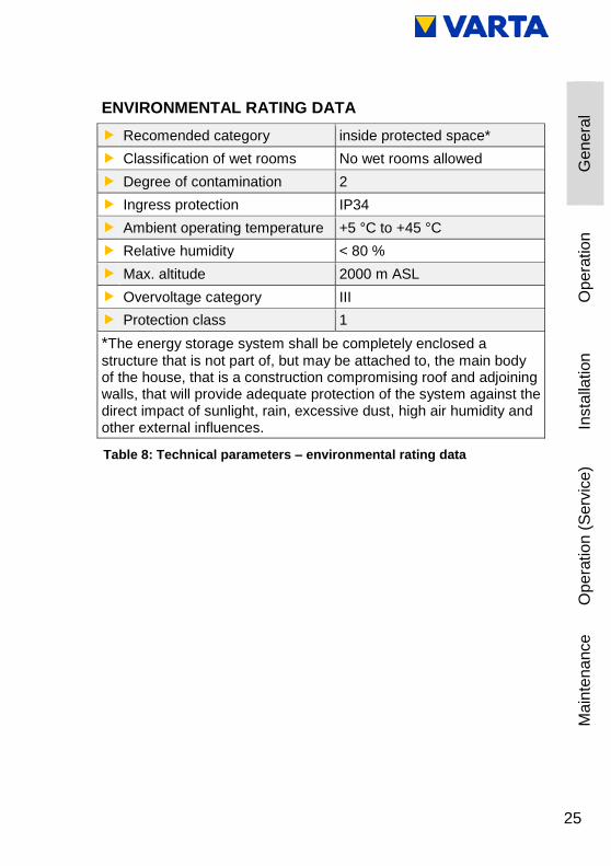
ENVIRONMENTAL RATING DATA
Recomended category inside protected space*
Classification of wet rooms No wet rooms allowed
Degree of contamination 2
Ingress protection IP34
Ambient operating temperature +5 °C to +45 °C
Relative humidity < 80 %
Max. altitude 2000 m ASL
Overvoltage category III
Protection class 1
*The energy storage system shall be completely enclosed a
structure that is not part of, but may be attached to, the main body of the house, that is a construction compromising roof and adjoining walls, that will provide adequate protection of the system against the direct impact of sunlight, rain, excessive dust, high air humidity and other external influences.
Table 8: Technical parameters – environmental rating data
26
Operation
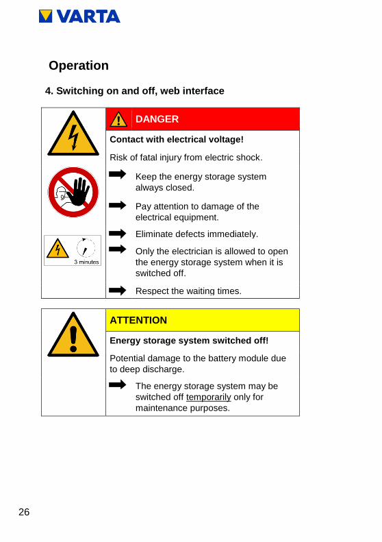
4. Switching on and off, web interface
DANGER
Contact with electrical voltage!
Risk of fatal injury from electric shock.
Keep the energy storage system
always closed.
Pay attention to damage of the
electrical equipment.
Eliminate defects immediately.
Only the electrician is allowed to open
the energy storage system when it is
switched off.
Respect the waiting times.
ATTENTION
Energy storage system switched off!
Potential damage to the battery module due
to deep discharge.
The energy storage system may be
switched off temporarily only for
maintenance purposes.
27
Ge
ne
ral
Op
era
tio
n
Insta
llation
Op
era
tio
n (
Serv
ice
) M
ain
ten
ance
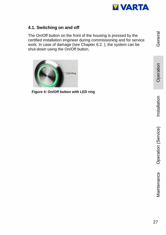
4.1. Switching on and off
The On/Off button on the front of the housing is pressed by the certified installation engineer during commissioning and for service work. In case of damage (see Chapter 6.2. ), the system can be shut-down using the On/Off button.
Figure 4: On/Off button with LED ring

28
4.2. LED ring indications
The LED ring at the On/Off button indicates the states and events which occur while the energy storage system is in operation.
LED ring colour LED action Operating state
Green
Flashes every second
(approx. 90 s) System check
Green
Steady light Ready
Green
Flashes every 3 s Standby
Green
Pulses with increasing
intensity Charge
Green
Pulses with decreasing
intensity Discharge
Green-
red
Flashes Update
Red
Steady light Error*
Red
Flashes every second Current sensor
check failed
*The i-button on the welcome page of the web interface displays information about current errors (see Chapter 4.3.2 ).
Table 9: LED ring indications at the On/Off button
29
Ge
ne
ral
Op
era
tio
n
Insta
llation
Op
era
tio
n (
Serv
ice
) M
ain
ten
ance
4.3. Web interface
The web interface offers the option of configuring settings, as well as monitoring and controlling the energy storage system functions.
4.3.1 Access to the web interface
To access the web interface, you will need the serial number of the energy storage system. The serial number can be found on the rating plate on the outside of the housing (top). See Figure 3: Rating plate.
Connect your storage system to the router of your home network by means of the network cable. The connection (RJ45 socket) is located on the right side of the housing. See Figure 15: Battery inverter sockets (bottom)
Enter into the address line of your browser after http://varta the serial number of the energy storage system. e.g.: http://varta130023456
The welcome page of the web interface will appear.
i Access to the web interface might require the browser to be refreshed.
The web interface is factory-tested with the following browsers: Firefox, Internet Explorer, Chrome and Opera.

30
4.3.2 Information on the welcome page (Home)
The welcome page provides an overview of the current power values and the states of the energy storage system:
(1) Charge power of the battery inverter in watt (W):
The energy storage system is charged with this power (power of the generating units, e.g. PV system, CHP, minus the direct internal consumption).
(2) Discharge power of the battery inverter in watt (W):
The energy storage system is discharged with this power.
Figure 5: Web interface: Welcome page

31
Ge
ne
ral
Op
era
tio
n
Insta
llation
Op
era
tio
n (
Serv
ice
) M
ain
ten
ance
(3) Power of the grid supply/grid draw (W):
The power supplied into the public grid or drawn from the public grid is displayed.
(4) Operating state of the energy storage system:
The operating state, e.g. standby, charging, error is displayed.
(5) The charging state of the energy storage system in %:
The charge level of the energy storage system is displayed.
(6) WWW:
Indicates whether the energy storage system is connected to the VARTA server (green = online, red = offline).
(7) Info button (i):
Displays information about the storage system, e.g. IP address, energy counter, or the most recent grid faults.
To see further explanations, move the cursor over the symbols.
4.4. External relays (optional)
Via the web interface, up to four external relays can be individually programmed for controlling special functions, such as switching consumers or generating units on/off. Clicking the Ext. relay button shows the corresponding page.
A download available from www.varta-storage.com provides further information.

32
4.5. Portal (optional)
The www.varta-storage-portal.com portal serves to monitor and visualise energy storage systems. To ensure continuous data transmission, the Internet connection must not be interrupted for longer than five days.
Access to the portal is activated once the "I wish to use the VARTA Storage Online Portal" prompt that appears during online login to the storage system is confirmed. A download is available from www.varta-storage.com for the online login to the storage system and for using the portal (see Chapter 8.5. Warranty registration).
Use of the Online Portal is free-of-charge. The Internet connection costs must be borne by the customer. However, there is no entitlement to access the portal (see the Terms and Conditions for the Online Portal in the download area).
i The data displayed on the VARTA Storage
portal cannot be used for billing purposes.

33
Ge
ne
ral
Op
era
tio
n
Insta
llation
Op
era
tio
n (
Serv
ice
) M
ain
ten
ance
5. Maintenance and cleaning
WARNING
Improper execution of maintenance and cleaning work!
Possible mortal danger.
Ensure that only qualified electricians
certified by VARTA Storage carry out
maintenance and cleaning work.
Only original parts are to be used for
maintenance work.
5.1. Maintenance work
Maintenance of the energy storage system includes:
Service (= inspection and maintenance)
Repair and technical improvements and any additions
To maintain the warranty entitlement (outside of Germany, Austria and Switzerland: to safeguard any warranty claims), the first service must be carried out within two years of the installation date. Subsequent servicing must be at three year intervals.
Please note that the SD card has a limited service life. To ensure continuous data storage, we recommend that you replace the SD card every two years. The SD card of the manufacturer: GOODRAM type No.: SDU4GCMGRB was successfully tested.

34
i Retain the service booklet together with the
instruction manual.
The extent of the maintenance work is described in the Chapter Maintenance.
5.2. Cleaning
WARNING
Entry of water into electrical systems!
Possible mortal danger.
Do not use water for cleaning the
energy storage system.
Never put down containers with fluids
(beverage containers and the like) on
electrical systems.
Cleaning agents
Do not use any cleaning agents containing acid, lye or solvents!
Cleaning the outside of the housing
clean with a vacuum cleaner.
wipe with a damp, not wet, cloth.

35
Ge
ne
ral
Op
era
tio
n
Insta
llation
Op
era
tio
n (
Serv
ice
) M
ain
ten
ance
6. Malfunction/event of damage
WARNING
Improper elimination of malfunctions!
Possible mortal danger.
Ensure that only qualified electricians certified by VARTA Storage carry out work at the energy storage system.
i In case of a malfunction, contact the qualified
electrician.

36
6.1. Malfunction indicators
6.1.1 Malfunction indicators of the LED ring
The LED ring of the On/Off button on the front of the housing indicates malfunctions. See Table 9, Chapter 4.2. .
6.1.2 Malfunction indicators on the web interface
Malfunctions are displayed on the welcome page of the web interface.
To do this, click on the i icon.
A window will open. Any pending system errors and the previous five grid faults can be read from this window.
6.2. Behaviour in the event of damage
WARNING
Improper handling in case of fire and flooding!
Possible mortal danger.
If possible, switch off the system and circuit-breakers.
Leave the hazard zone.
In case of fire, call the fire brigade immediately.
Inform the fire brigade about the lithium-ion batteries inside the energy storage system.

37
Ge
ne
ral
Op
era
tio
n
Insta
llation
Op
era
tio
n (
Serv
ice
) M
ain
ten
ance
i In the event of a fire or flooding, prudent
behaviour can limit the damage.
WARNING
Damaged battery module due to technical defect!
Pungent smell.
Avoid contact with possibly leaking fluid.
Avoid contact with possibly escaping vapours.
If possible, switch off the system and disconnect the fuses.
Avoid sparks and open flames.
Ventilate the installation room.
In case of a malfunction, contact the qualified electrician.

38
Installation
This section is intended for the qualified
electrician.
7. Transport and storage
7.1. Transport
Lithium-ion batteries are hazardous goods. The battery modules are constructed and tested in a way, so they are allowed to be transported up to a total weight of 333 kg by complying with the conditions of ADR 1.1.3.6 (transport not subject to labelling, as long as there are no other hazardous goods on or inside the vehicle). The other requirements of GGVSEB (ordinance on the national and international carriage of hazardous goods by road, rail, and inland waterways) and ADR (Agreement on Dangerous Goods by Road) also have to be fulfilled. Delivery is made in tested hazardous goods packaging.
Lithium-ion batteries were successfully tested according to UN 38.3 transport test (UN Manual of Tests and Criteria, Part III, subsection 38.3) and have passed.
The housing is packed separately from the battery module.

39
Ge
ne
ral
Op
era
tio
n
Insta
llation
Op
era
tio
n (
Serv
ice
) M
ain
ten
ance
7.2. Transportation regulations and safety instructions
WARNING
Improper transport due to lack of professional knowledge!
Possible mortal danger and material damage.
The transportation of the energy storage system and its components is only allowed to be carried out by the manufacturer and the electricians qualified and certified by him.
Be prudent during transport.
Adhere to the transportation regulations.
Energy storage system and battery modules
must not be temporarily stored in the transport vehicle.
The energy storage system must not be transported if a battery module has already been installed.
The driver or co-driver are not allowed to open the outer packaging of a battery module.

40
Energy storage system and battery modules
A tested ABC fire extinguisher with a minimum capacity of 2 kg has to be carried along.
Heed the symbols on the packaging.
Transport the parts only in enclosed vehicles.
The load has to be properly secured.
Transport the battery module only in its intended transport packaging.
Adhere to the requirements according to GGVSEB and ADR.
Use your personal protective equipment.
This reduces the risk of injuries during the mechanical work.
WARNING
Components are heavy!
This might lead to overburdened intervertebral discs, bruises and crushing.
Carry out the work described in this chapter with 2 persons or suitable equipment.

41
Ge
ne
ral
Op
era
tio
n
Insta
llation
Op
era
tio
n (
Serv
ice
) M
ain
ten
ance
i When exchanging a battery module, request
new hazardous goods packaging if required,
pack the battery module and have it picked up
by the supplier.
7.3. Packaging/transport control
DANGER
Installation of damaged components!
Mortal danger.
Do not accept clearly damaged packaging.
Contact VARTA Storage.
The housing and battery module (individually packaged) are delivered in separate and tested packaging units on pallets. The disposal of the packaging will be taken over by the installation engineer. Please examine the deliveries on completeness and damages:
If damages are already visible at the packaging, please note this down on the delivery documents and have the driver confirm this by signature.
If the packaging is severely damaged, reject the deliveries.
i Do not remove the packaging until immediately prior to installation. This prevents damage. Keep the packaging material, so the system can be properly packaged in case of a subsequent transport (relocation).

42
7.4. Storage
WARNING
Entry of water into electrical systems!
Short-circuit and corrosion due to condensation.
Adhere to the storage conditions.
The housing and the battery module
must not be temporarily stored in the transport vehicle.
must not be stored outdoors.
do not expose to abrupt temperature changes.
The housing and the battery module
are to be stored dry, at a humidity of < 80 %.
are to be stored at a temperature of 5-45 °C (optimum: +18 C).
ATTENTION
Material damage due to overly long storage!
Deep discharge of the battery module!
Adhere to the storage conditions.
The battery module
must be commissioned by the manufacturer or a qualified electrician certified by VARTA Storage within eleven weeks of being delivered.
43
Ge
ne
ral
Op
era
tio
n
Insta
llation
Op
era
tio
n (
Serv
ice
) M
ain
ten
ance
8. Assembly and installation
This section is intended for the qualified
electrician.
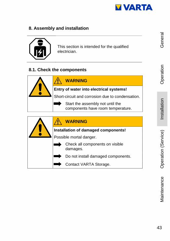
8.1. Check the components
WARNING
Entry of water into electrical systems!
Short-circuit and corrosion due to condensation.
Start the assembly not until the components have room temperature.
WARNING
Installation of damaged components!
Possible mortal danger.
Check all components on visible damages.
Do not install damaged components.
Contact VARTA Storage.

44
8.2. Requirements for the installation location
This section is intended for the qualified
electrician.
WARNING
Entry of water into electrical systems!
Mortal danger from electric shock.
Install the storage cabinet only inside a protected space.
Observe all requirements for the installation location.
CAUTION
Personal injury and material damage due to wrong installation and lack of space!
Crush injuries of limbs.
Place the cabinet, so a safe installation, operation, maintenance and disassembly are possible when used properly.

45
Ge
ne
ral
Op
era
tio
n
Insta
llation
Op
era
tio
n (
Serv
ice
) M
ain
ten
ance
8.3. Installation location
The following dimensions and framework conditions have to be complied with at the installation location.
8.3.1 Dimensions and features
Recommended volume of min. 30 m³, a vertical, flat wall surface of min. 200 cm x 90 cm (height x width). It must have sufficient load-bearing capacity, i.e. for 4 times the weight of the energy storage system itself.
Weight of the energy storage system Chapter 3.7. Technical parameters.
If necessary, have the statics tested.
The ground, the adjacent walls and ceiling must not consist of heat-sensitive material.
The distance to adjacent installations must be at least 15 cm to the right and left. A clear space of approx. 120 cm in depth is required in front of the device to carry out installation and maintenance work from the front. In order to secure the means of escape, doors must not swing into this clear space.
The screws for opening the housing must be accessible from below. Comply with the min. dimensions in Figure 14: "Dimensions on mounting plate (mm)."
46
A minimum clearance of 30 cm must be left above the housing. To ensure that the cooling air can exit the unit unhindered, the min. clearance of 15 cm to either side must be ensured.
8.3.2 Environmental conditions
The installation location must match a pollution degree 2.
A continuous air exchange, possibly via forced ventilation, e.g. window, air-conditioning system, ventilation or the like, has always to be ensured. The distance to the ventilation must be at least 100 cm.
The temperature at the installations location must always be
between 545 °C (optimum +18 °C), the relative humidity must be < 80 %.
Recommendation: well ventilated room without external heat sources.
Sufficient rodent protection must be provided.
Smoking is not allowed at the installation
location.

47
Ge
ne
ral
Op
era
tio
n
Insta
llation
Op
era
tio
n (
Serv
ice
) M
ain
ten
ance
8.3.3 Impermissible locations and environmental conditions
Altitudes above 2,000 metres or other places, at which the environmental conditions are not satisfied.
Locations:
with unsuitable climatic or geographical conditions,
with an explosive atmosphere,
at which flammable or oxidising substances are stored,
wet rooms,
with high fluctuations of the ambient temperature,
with direct sunlight,
with a humidity above 80 % and condensation,
in which the temperature might be below the freezing point,
in which salty humidity might enter,
with an ammonia-containing environment.
8.4. Warranty
For the warranty to be effective (to safeguard any warranty claims outside Germany, Austria and Switzerland), VARTA Storage must be in possession of the following data:
Commissioning report (including date of commissioning).
Serial number (SN number) of the VARTA system. The ID label (rating plate) of the system is affixed inside the storage cabinet.
Serial number of the battery module. The ID label of the battery module is enclosed in the packaging.
The installation engineer enters these data in the VARTA Storage installation engineer portal. Within four weeks of the installation date, the customer must register their data (name, address, email address, telephone number) at www.varta-storage-portal.com and enter the serial number (SN number) of the energy storage system

48
and the activation code. The installation engineer can also register the data, subject to the customer's consent.
The activation code label (Unlock Code) is affixed to the inside of the storage cabinet on the inside of the hood. This label is provided for the customer's personal documents.
Figure 6: Example of ID label for the system (in the hood)
Figure 7: ID label of the battery module (example)

49
Ge
ne
ral
Op
era
tio
n
Insta
llation
Op
era
tio
n (
Serv
ice
) M
ain
ten
ance
Figure 8: Activation code label (example)

50
8.5. Warranty registration
This online-based warranty registration consists of two parts:
Part 1: Registration of the energy storage system by the installation engineer incl. commissioning report (Chapter 8.5.1 )
Part 2: Warranty registration by the end customer incl. registration for the web portal (Chapter 8.5.2 )
8.5.1 Warranty registration by the installation engineer
Open page www.varta-storage.com Change to "energy storage systems"
Registration in the B2B area with login and password
On the welcome page, click on "Start VARTA-Portal" Change to "energy storage registration"
Entering the data for the battery storage:
o Initial installation/retrofit,
o Date,
o Installation engineer,
o Serial number,
o Activation code,
51
Ge
ne
ral
Op
era
tio
n
Insta
llation
Op
era
tio
n (
Serv
ice
) M
ain
ten
ance
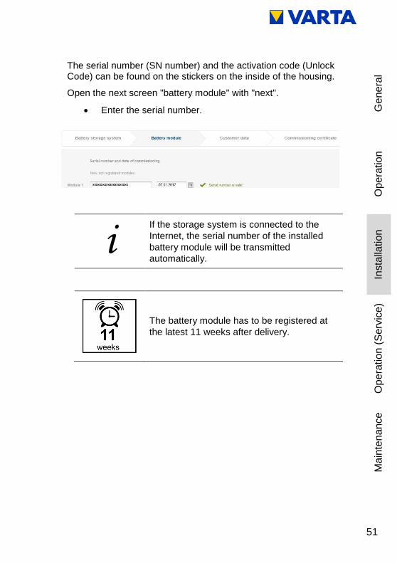
The serial number (SN number) and the activation code (Unlock Code) can be found on the stickers on the inside of the housing.
Open the next screen "battery module" with "next".
Enter the serial number.
i If the storage system is connected to the
Internet, the serial number of the installed
battery module will be transmitted
automatically.
The battery module has to be registered at
the latest 11 weeks after delivery.

52
Call up the next screen "customer data" with "next".
Determine whether the customer agrees that the installation engineer completes the following fields and transmits them to VARTA Storage.
If "Yes", continue with the next screen
If "No", the screen "customer data" will be skipped. In this case, the end customer has to enter these data in the 2nd part of the warranty registration himself.
Entering the customer data.
Mandatory fields are marked with an *.
Call up the next screen "commissioning" with "next".

53
Ge
ne
ral
Op
era
tio
n
Insta
llation
Op
era
tio
n (
Serv
ice
) M
ain
ten
ance
Details of the commissioning report.
54
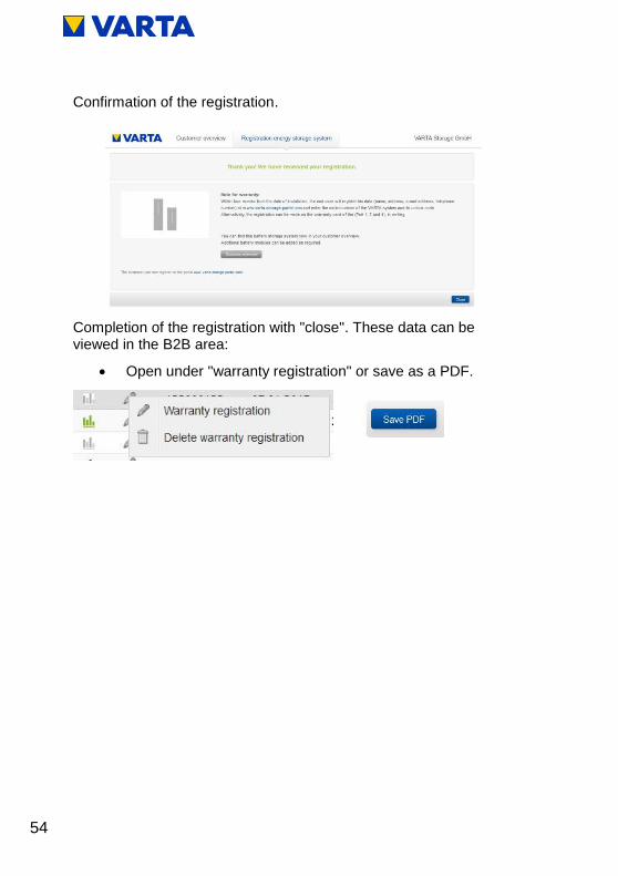
Confirmation of the registration.
Completion of the registration with "close". These data can be viewed in the B2B area:
Open under "warranty registration" or save as a PDF.

55
Ge
ne
ral
Op
era
tio
n
Insta
llation
Op
era
tio
n (
Serv
ice
) M
ain
ten
ance
8.5.2 Warranty registration by the customer
Open page www.varta-storage.com Change to "energy storage systems"
Registration in the portal
Under: "No access yet? Register now" with serial number and activation code.
Enter the following details:
Battery storage,
Contact data,
Declaration for contacting via telephone,
Declaration for the use of the online services plus contacting via telephone,
Cancellation right information,
Voluntary consents of the customer.

56

57
Ge
ne
ral
Op
era
tio
n
Insta
llation
Op
era
tio
n (
Serv
ice
) M
ain
ten
ance
Click the button "Send registration now".
After completion of the entries, the details of the warranty registration are displayed.
Correct the entries or send the registration now.

58
After registration, the customer receives an email with the access data.

59
Ge
ne
ral
Op
era
tio
n
Insta
llation
Op
era
tio
n (
Serv
ice
) M
ain
ten
ance
8.6. Preparation of the electrical connection
This section is intended for the qualified
electrician.
Use your personal protective equipment.
This reduces the risk of injuries during the mechanical work.
Observe the safety rules!
Disconnect.
Lock out.
Check for absence of voltage.
Before connecting up the power supply, make sure that no persons are in the hazard zone.

60
WARNING
Improper installation!
Personal injury and material damage.
The fuse for the energy storage system must meet the requirements for a disconnecting device.
Fuse the device connection at the energy storage system with a 16 A fuse type B.
Observe the disconnect conditions in accordance with VDE 0100-410.
Never connect the energy storage system without a PE and N connection.
The system is intended to have a permanent connection. Neutral and phase must not be interchanged. Otherwise, internal protection and metering devices might not function.
A suitable separator must be installed between power grid and customer system (e.g. selective automatic cut-out 'SAC'), which can be used for all-poles disconnection of the customer system from the grid during maintenance work.
Observe the specified conductor cross-sections.
For the position of the separators, see the connection diagrams (Figures 1 - 4) in the Appendix.

61
Ge
ne
ral
Op
era
tio
n
Insta
llation
Op
era
tio
n (
Serv
ice
) M
ain
ten
ance
8.6.1 Connections to the distributor box
The following connections must be prepared:
Device connection:
Recommendation: 3 x 2.5 mm²
Sensor cable: RJ12 (included in delivery)
LAN connection
i (1) Do not allow any mechanical load on the sensor
cable.
(2) In order to minimise losses, the wiring section between storage and connection should not be longer than 20 m.
8.6.2 Preparation of the AC port for the building grid
To connect to the building grid, the 3-wire AC cable must be connected to the supplied AC connector.
Strip the cable 55 mm at the end.
The PE conductor must be 8 mm longer than the other four conductors. Shorten these conductors accordingly.
Strip the insulation off the ends of the conductors in the cable for a length of approx. 9 mm.
Connection of a solid-wire conductor: Insert the stripped conductor as far as possible.
Figure 9: Stripping cables

62
Figure 10: AC connector
Connection of a stranded-wire conductor: Press the clamping springs with a screwdriver (2.5 mm blade width) Insert the stripped conductor as far as possible.
To release the conductor, press the springs with a screwdriver.
1 AC connector
2 Strain relief housing (lower part)
3 Strain relief housing (upper part)
Figure 11: AC connector with strain relief

63
Ge
ne
ral
Op
era
tio
n
Insta
llation
Op
era
tio
n (
Serv
ice
) M
ain
ten
ance
Form the connection cable.
Place the strain relief housing on the connection piece and insert the cable.
Snap the upper part of the strain relief into place and draw together with the screw.
8.6.3 VARTA Split Core current sensor
If the energy storage system to be installed is to be cascaded with further energy storage systems, the following step will not be carried out. Instead, see instruction manual for cascading (Optional add-on package required).
ATTENTION
Reversed phases!
Charging and discharging malfunction.
Conductors L1, L2, L3 for the building
connection and PV current sensor must
have the same phase assignment.
Make the connection for a clockwise
phase sequence.
ATTENTION
Contamination of the magnetic cores!
The current sensor will be damaged.
Do not touch the magnetic cores.
Ensure a clean working environment.
In order to ensure optimisation of in-house consumption, the current sensor must capture all values of consumption and infeed. Therefore, it is located directly behind the consumption and feed meter. The VARTA Split Core Stromsensor consists of a connection box and three folding transformers. Each has a nominal

64
current rating of 50 A (maximum current 100 A) per phase. The connection box is designed for top hat-rail mounting. The connection for the sensor cable provided for connecting to the energy storage system is located in the connection box. For the location of the "Current measurement" socket on the energy storage system, see Figure 15: "Battery inverter sockets (bottom)".
For the VARTA Split Core current sensor to detect the reference and in-fed power correctly, it is necessary to adhere to the following:
The phase assignment L1, L2, L3 must provide a clockwise phase sequence.
The arrows on the folding transformers must point in the sub-distribution direction.
1 VARTA pulse
2 VARTA Split Core current sensor
3 Grid
4 Optional a second one of VARTA Split Core current
sensor.

65
Ge
ne
ral
Op
era
tio
n
Insta
llation
Op
era
tio
n (
Serv
ice
) M
ain
ten
ance
To attach the folding transformer to the VARTA Split Core current sensor, guide the wire through the opening in the blue folding transformer. Open the latch on the back, place the folding transformer around the wire and close it again. The latch must engage audibly.
1 Current sensor
2 "Current measurement" connection socket
3 folding transformer (L1, L2, L3)
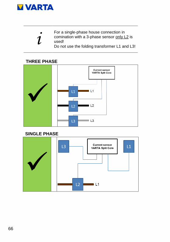
Figure 12: VARTA Split Core current sensor (Single Phase)
Figure 13: VARTA Split Core current sensor (Three Phase)
66
i For a single-phase house connection in comination with a 3-phase sensor only L2 is used!
Do not use the folding transformer L1 and L3!
THREE PHASE
SINGLE PHASE

67
Ge
ne
ral
Op
era
tio
n
Insta
llation
Op
era
tio
n (
Serv
ice
) M
ain
ten
ance
NOT PERMITTED
PV current transformer (optional)
VARTA pulse has a provision for connection of an additional VARTA Split Core current sensor for visualization of the power from the provider.
In this case:
The phases of the building's current sensor must match the phases of the PV current sensor.
The arrows on the folding transformers point in the sub-distribution direction.

68
8.7. Preparation of assembly
This section is intended for the qualified
electrician.
Read the instruction manual.
WARNING
Components are heavy!
This might lead to overburdened intervertebral discs, bruises and crushing.
Carry out the work described in this chapter with 2 persons or suitable equipment.
i The device is not designed to be used in
three-phase combinations.

69
Ge
ne
ral
Op
era
tio
n
Insta
llation
Op
era
tio
n (
Serv
ice
) M
ain
ten
ance
8.8. Installing and connecting the energy storage system
(1) Mark the positions of the upper right and left holes as shown in Figure 14 "Dimensions on mounting plate (mm)". (Position 1 in the drawing)
(2) Remove the mounting plate with battery inverter from the worksite.
Note: No dust from drilling must be allowed to get in or on the unit.
(3) Drill holes at both positions and screw in the screws so that there is a distance of approx. 3 mm between the wall and screw head.
(4) Remove the carrying straps from the mounting plate.
(5) Install the mounting plate.
Note: Make sure that the mounting plate slides down into the keyholes.
(6) Check that the mounting plate is level.
(7) Mark the remaining 4 holes (position 2 in the drawing).
(8) Remove the mounting plate.
(9) Drill the four holes.
(10) Install the mounting plate.
(11) Screw the mounting plate to the wall securely.
Connect the current sensor (Figure 13: VARTA Split Core current sensor (Three Phase)) to the energy storage system (Figure 15: Battery inverter sockets (bottom).
(1) Insert the AC connector into the AC grid socket.
(2) Insert the sensor cable and the network cable into the corresponding sockets.
i Use suitable fasteners!

70
Figure 14: Dimensions on mounting plate (mm)

71
Ge
ne
ral
Op
era
tio
n
Insta
llation
Op
era
tio
n (
Serv
ice
) M
ain
ten
ance
AC connection area
1 Micro-SD card slot
2 LAN
3 PV sensor (optional)
4 Grid sensor
5 AC grid
6 Main earth (PE) (2x)
i
Note that the specific country code must be set on
the country selector switch. Read the
accompanying bulletin.
Figure 15: Battery inverter sockets (bottom)

72
8.9. Battery module assembly
This section is intended for the qualified
electrician.
DANGER
Contact with live parts!
Mortal danger.
Adhere to the waiting times.
Make sure that the battery module is switched off and no LED indicator is lit.
The energy storage system must not be transported if a battery module has already been installed.
Keep unauthorised persons away.
WARNING
Contact with sharp-edged parts!
Cut injuries.
Wear your personal protective equipment.
73
Ge
ne
ral
Op
era
tio
n
Insta
llation
Op
era
tio
n (
Serv
ice
) M
ain
ten
ance
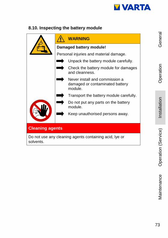
8.10. Inspecting the battery module
WARNING
Damaged battery module!
Personal injuries and material damage.
Unpack the battery module carefully.
Check the battery module for damages and cleanness.
Never install and commission a damaged or contaminated battery module.
Transport the battery module carefully.
Do not put any parts on the battery module.
Keep unauthorised persons away.
Cleaning agents
Do not use any cleaning agents containing acid, lye or
solvents.

74
8.11. Behaviour in the event of damage
WARNING
Improper handling in case of damaged battery module!
Personal injuries and material damage.
Do not open the battery module.
Do not attempt to repair it.
Avoid contact with possibly leaking
fluid.
Avoid contact with possibly escaping
vapours.
Damaged or contaminated battery module
Contact VARTA Storage.
First aid in case of contact with electrolyte
When inhaling: Leave the room.
Get medical attention immediately.
In case of skin contact: Thoroughly wash the affected area
with water and soap.
Get medical attention immediately.
In case of eye contact: Rinse eyes with running water for at
least 15 minutes.
Get medical attention immediately.

75
Ge
ne
ral
Op
era
tio
n
Insta
llation
Op
era
tio
n (
Serv
ice
) M
ain
ten
ance
8.12. Installing and connecting the battery module
ATTENTION
Overly long storage of the battery module!
Deep discharge of the battery module.
Once you started commissioning, it has to be carried out until finished.
ATTENTION
Reversed wires of error and warning messages.
Wrong error message to the control.
Observe the given colour-coding.
Figure 16: VARTA pulse battery module
76
8.12.1 Installing the battery module
WARNING
Improper handling of the battery module!
Personal injury and material damage.
Carry out the work described in this
chapter with 2 persons or suitable
equipment.
Do not lift the battery module by the
handle.
Use the handle to guide the battery
module during installation.
The battery module is positioned as shown in Figure 18: "Battery module fastening screws".
Lift the battery module onto the two mounting rails on the mounting plate.
The handle is intended only for guiding the battery module.
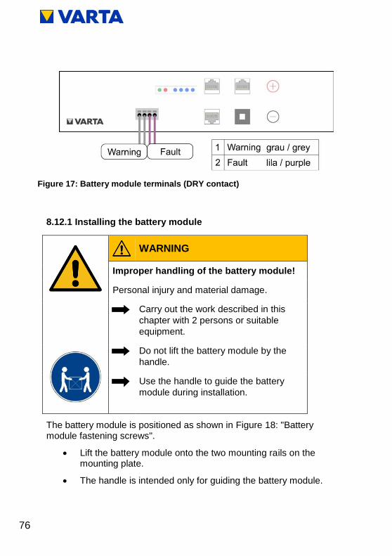
Figure 17: Battery module terminals (DRY contact)

77
Ge
ne
ral
Op
era
tio
n
Insta
llation
Op
era
tio
n (
Serv
ice
) M
ain
ten
ance
The oblong holes on the battery module serve to centre the battery module using the two preinstalled screws.
Push the battery module back and secure it by means of the four screws provided.
Make the connections to the battery module as shown in Figure 19: "Internal connections".
Figure 19: Internal connections
Figure 18: Battery module fastening screws

78
Battery power connection: Plug on both connectors with correct polarity.
Every connector must engage audibly.
Communication 1:
Insert the four communication cables into the openings in the clamping connector. The connections are self-clamping. For the pin assignment, see Figure 17: "Battery module terminals (DRY contact)"
Communication 2:
Plug in the communication cable (red, CAN).
Check readiness for operation: Press the activation button on the battery module.
The LED indicator on the battery module indicates that the unit is ready for operation.

79
Ge
ne
ral
Op
era
tio
n
Insta
llation
Op
era
tio
n (
Serv
ice
) M
ain
ten
ance
8.12.2 Closing the energy storage system
WARNING
Damaged cables due to improper assembly!
Electric shock!
Check all assembly steps before closing
the energy storage system.
Do not use any force when closing the
hood.
ATTENTION
On/Off switch could be damaged!
System cannot be put into operation.
Do not use any force when closing the
hood; the switch must fit in the opening
in the battery inverter.
Before you close the energy storage system, please check:
all tools removed?
is the interior clean?
o no loose parts in the interior?
o no small parts in the interior?
all cable connections correctly established?
all cable bushings installed correctly?
edge protection installed at the intended locations?
Make any necessary corrections.
80
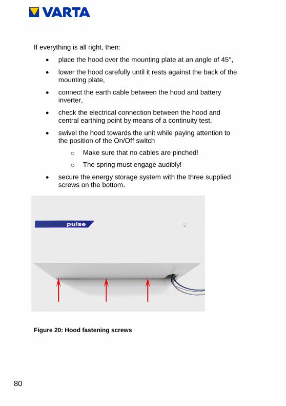
If everything is all right, then:
place the hood over the mounting plate at an angle of 45°,
lower the hood carefully until it rests against the back of the mounting plate,
connect the earth cable between the hood and battery inverter,
check the electrical connection between the hood and central earthing point by means of a continuity test,
swivel the hood towards the unit while paying attention to the position of the On/Off switch
o Make sure that no cables are pinched!
o The spring must engage audibly!
secure the energy storage system with the three supplied screws on the bottom.
Figure 20: Hood fastening screws

81
Ge
ne
ral
Op
era
tio
n
Insta
llation
Op
era
tio
n (
Serv
ice
) M
ain
ten
ance
8.13. Initial commissioning
This section is intended for the qualified electrician.
8.13.1 Switching on
The VARTA energy storage system is switched on as follows:
Housing closed and secured by screws.
Make sure that the network cable is connected.
Connect the fuse at the building grid.
Activate storage system using On/Off button. The button will be locked in the lower position.
Figure 21: On/Off button

82
The initialisation process can be tracked at the LED ring of the On/Off button.
LED ring colour LED action Operating state
Green
Flashes every
second
Duration approx.
90 s
System check
Green
Steady light Ready
Red
Steady light
Probable error:
The battery modules
have not yet been
configured.
Continue with commissioning!
LED ring colour Possible cause Remedy
White
On/Off button
not pressed Press On/Off button
Hood not
positioned
correctly
Open hood and then
position it as instructed
Fuse not
switched on Switch on fuse
No AC grid
connection
Check AC grid
connection and
establish, if necessary
Switch defective Check switch and
replace, if necessary
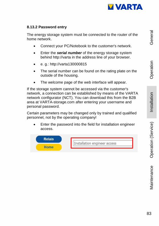
83
Ge
ne
ral
Op
era
tio
n
Insta
llation
Op
era
tio
n (
Serv
ice
) M
ain
ten
ance
8.13.2 Password entry
The energy storage system must be connected to the router of the home network.
Connect your PC/Notebook to the customer's network.
Enter the serial number of the energy storage system behind http://varta in the address line of your browser.
e. g.: http://varta130000815
The serial number can be found on the rating plate on the outside of the housing.
The welcome page of the web interface will appear.
If the storage system cannot be accessed via the customer's network, a connection can be established by means of the VARTA network configurator (NCT). You can download this from the B2B area at VARTA-storage.com after entering your username and personal password.
Certain parameters may be changed only by trained and qualified personnel, not by the operating company!
Enter the password into the field for installation engineer access.

84
Further tabs appear in the header.
For a simplified installation, you can use the menu Quick Install (see Chapter 8.14. ).
8.13.3 Entering the serial numbers of the battery module
Click on the Settings tab (1).
The Settings page opens.
Click on the Basic settings tab (4).
Enter an individual name (2) for the device. The maximum length is 20 characters.
Enter the serial number of the installed battery module (3).
Click on Apply.

85
Ge
ne
ral
Op
era
tio
n
Insta
llation
Op
era
tio
n (
Serv
ice
) M
ain
ten
ance
Once the correct serial numbers have been entered, the LED ring indicator changes from red to green.
If the LED remains red or flashes red, the following remedies have to be taken
Remedy: LED ring flashes red
Error:
The current sensor check failed. Please switch the battery storage
system off and back on again.
Check the connection to the current sensor. Check that the phase
assignment on the current sensor is for a clockwise phase
sequence.
If the LED ring continues to flash red after the restart (duration
approx. 3 minutes), check the connection to the current sensor.
If the LED ring continues to flash red, please contact VARTA
Storage.
i
The storage system cannot be commissioned
unless the correct serial number of the battery
module is provided.

86
8.13.4 Portal connection
Select the Network tab from Settings.
By default, the storage system uses the settings of the customer's network; for this, the selection field next to Activate DHCP is ticked (factory setting).
If the connection is not made automatically, use the parameters in the instructions for the network router. DNS and gateway address are usually identical for commercially available DSL routers. These addresses can differ for company networks. Moreover, ports 4500, 21 and 37 need to be enabled for the connection to the portal (does not apply for all users).
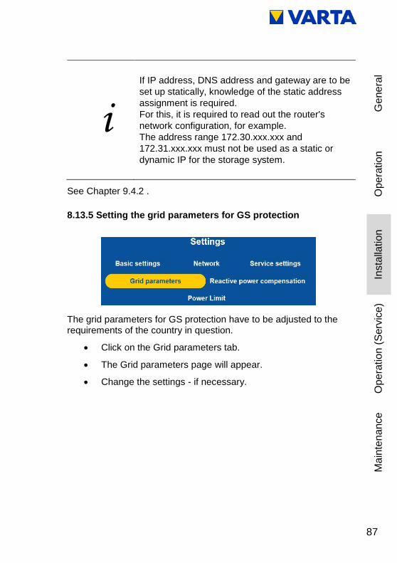
87
Ge
ne
ral
Op
era
tio
n
Insta
llation
Op
era
tio
n (
Serv
ice
) M
ain
ten
ance
i
If IP address, DNS address and gateway are to be
set up statically, knowledge of the static address
assignment is required.
For this, it is required to read out the router's
network configuration, for example.
The address range 172.30.xxx.xxx and
172.31.xxx.xxx must not be used as a static or
dynamic IP for the storage system.
See Chapter 9.4.2 .
8.13.5 Setting the grid parameters for GS protection
The grid parameters for GS protection have to be adjusted to the requirements of the country in question.
Click on the Grid parameters tab.
The Grid parameters page will appear.
Change the settings - if necessary.

88
Setting: Automatic
Check the Automatic option.
Select the country for which the settings are to apply from the dropdown list.
Click on Apply.
The Automatic setting uses the default values that are saved for the selected country (see Table 10).
For the individual grid parameter settings, see Chapter 9.4.4

89
Ge
ne
ral
Op
era
tio
n
Insta
llation
Op
era
tio
n (
Serv
ice
) M
ain
ten
ance
8.13.6 Reboot
A reboot is required after parameters are changed.
To do so, turn the storage system off and then back on again at the On/Off button.
Afterwards, checks on the welcome page and on the System page are necessary.
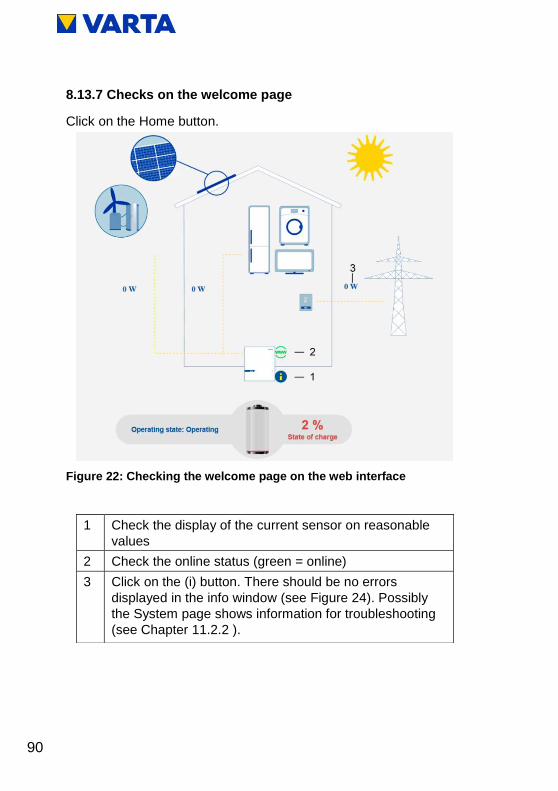
90
8.13.7 Checks on the welcome page
Click on the Home button.
Figure 22: Checking the welcome page on the web interface
1 Check the display of the current sensor on reasonable
values
2 Check the online status (green = online)
3 Click on the (i) button. There should be no errors
displayed in the info window (see Figure 24). Possibly
the System page shows information for troubleshooting
(see Chapter 11.2.2 ).

91
Ge
ne
ral
Op
era
tio
n
Insta
llation
Op
era
tio
n (
Serv
ice
) M
ain
ten
ance
8.13.8 Checks on the "System" page
Click on the System tab.
Checking the connections
Once the energy storage system has been setup and connected, it is necessary to check whether the system signals a current flow at all three phases (realistic currents).
Figure 23: Info window on the web interface

92
OVERVIEW BATTERY INVERTER
L1 L2 L3
I Grid -6,82 A -0,15 A -2,36 A
I PV 0.14 A -0.05 A 0.13 A
Sensor Phase
Phase 1
U Inv 0 V
An error has occurred if the value for the current (I grid) hovers between +0.01 and -0.01 on one of the connected phases. Check the cable connection to the current sensor.
If realistic values are not displayed, check whether the connection corresponds to a clockwise phase sequence.
Note: The system may need to have a large load at all three phases.
Checking the battery modules.
Check whether the Battery module serial number of the installed battery module is displayed.
Serial numbers oft the battery modules
EM048126P3S7BMA17031708023
8.13.9 Exiting the password-protected area
Finally, it is necessary to ensure that the customer is unable to access the password-protected area.
Click on the Logout tab.

93
Ge
ne
ral
Op
era
tio
n
Insta
llation
Op
era
tio
n (
Serv
ice
) M
ain
ten
ance
8.14. Quick Install
Click on the Quick Install tab.
Follow the wizard step by step.
Basic settings menu:
Enter the device name (2).
Enter the serial number of the battery module (3).
Click Next.

94
Network settings menu
The network settings will be applied unchanged.
Click Next.
Grid parameters menu
The grid parameters will be set to "Automatic". Select the appropriate country. For further information, see Chapter 9.4.4 .
Complete the Quick Install with Finish and switch the storage
system off and then back on again at the On/Off button.

95
Ge
ne
ral
Op
era
tio
n
Insta
llation
Op
era
tio
n (
Serv
ice
) M
ain
ten
ance
9. Operation in the password-protected area
This section is intended for the qualified electrician.
9.1. The password-protected area
9.1.1 Access to the web interface - password entry
The procedure for accessing the web interface is described in the Operation section. See Chapter 4.3.1 .
Certain parameters may be changed only by trained and qualified personnel, not by the operating company!
Enter the password into the field for installation engineer access.
Further tabs appear in the header.
Click on a tab.
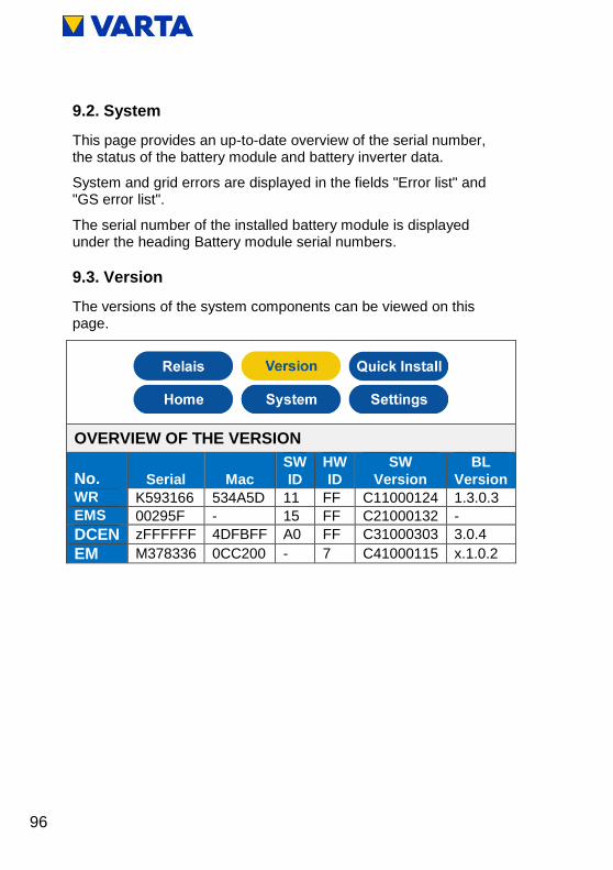
96
9.2. System
This page provides an up-to-date overview of the serial number, the status of the battery module and battery inverter data.
System and grid errors are displayed in the fields "Error list" and "GS error list".
The serial number of the installed battery module is displayed under the heading Battery module serial numbers.
9.3. Version
The versions of the system components can be viewed on this page.
OVERVIEW OF THE VERSION
No. Serial Mac
SW
ID
HW
ID
SW
Version
BL
Version
WR K593166 534A5D 11 FF C11000124 1.3.0.3
EMS 00295F - 15 FF C21000132 -
DCEN zFFFFFF 4DFBFF A0 FF C31000303 3.0.4
EM M378336 0CC200 - 7 C41000115 x.1.0.2

97
Ge
ne
ral
Op
era
tio
n
Insta
llation
Op
era
tio
n (
Serv
ice
) M
ain
ten
ance
9.4. Settings
The Settings page gives you access to other input screens.
Click on a tab.
Enter the parameters or check the corresponding selection box.
Confirm your entries by clicking on the Apply button.
Alternatively, you can restore the Factory settings or return to the previous operating state via Return.

98
9.4.1 Basic settings
Basic settings can be changed on this page:
Device name: Input during initial commissioning. The maximum length is 20 characters.
Date and time can be entered here. As a rule, these parameters are automatically synchronised via the time server.
Time zone: For Germany: GMT+1 (Greenwich Mean Time + 1 h).
Battery module serial number: Enter the serial number (SN) of the battery module here.
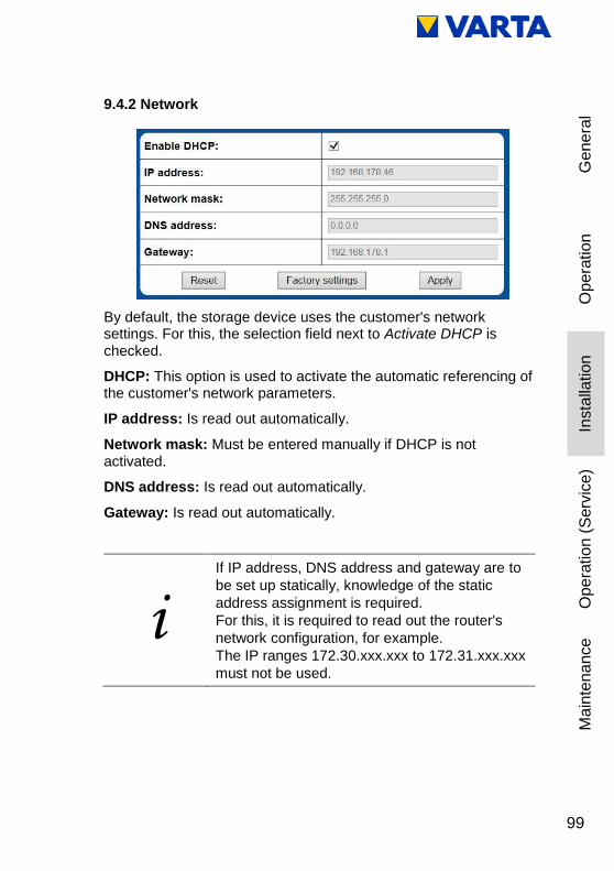
99
Ge
ne
ral
Op
era
tio
n
Insta
llation
Op
era
tio
n (
Serv
ice
) M
ain
ten
ance
9.4.2 Network
By default, the storage device uses the customer's network settings. For this, the selection field next to Activate DHCP is checked.
DHCP: This option is used to activate the automatic referencing of the customer's network parameters.
IP address: Is read out automatically.
Network mask: Must be entered manually if DHCP is not activated.
DNS address: Is read out automatically.
Gateway: Is read out automatically.
i
If IP address, DNS address and gateway are to
be set up statically, knowledge of the static
address assignment is required.
For this, it is required to read out the router's
network configuration, for example.
The IP ranges 172.30.xxx.xxx to 172.31.xxx.xxx
must not be used.

100
9.4.3 Service settings
The following parameters can be set on this page:
Reboot time: By default, the system reboots at between 3 and 4 o' clock. Any hour between 0 a.m. and 12 p.m. can be entered for the reboot time.
Manual fan actuation: Select between
Automatic (= 0), middle level (= 1) and highest level (= 2).
Resetting time of air filter change: The time until the next air filter change can be reset. To do so, check the selection field. It is assumed that the air filter is really replaced or cleaned.

101
Ge
ne
ral
Op
era
tio
n
Insta
llation
Op
era
tio
n (
Serv
ice
) M
ain
ten
ance
9.4.4 Grid parameters for GS protection
The grid parameters for GS protection for switching off have to be adjusted to the requirements of the respective country. This requires that the country selection switch be set to the correct position prior to commissioning. Read the accompanying bulletin.
Automatic: If the selection box is checked, the saved settings will be used for GS protection.
In the drop-down list, select the country to which the country selection switch is set. If the country displayed here does not match the switch setting, check the setting of the switch.
Minimum and maximum values: These values can be set in addition to the default values.

102
Standard values for some countries are stored in the device. These may be applied in the device (depends on the setting of the country selection switch). Some of the standard values are shown in Table 10 .
GRID PARAMETERS
Country FG
RID
_M
IN
(in H
z)
FG
RID
_M
AX
(in H
z)
UG
RID
_M
IN
(in V
)
UG
RID
_M
aX
(in
V)
UG
RID
_M
AX
10
(in V
)
Germany 47.50 51.50 184 264 253
Austria 47.50 51.50 184 264 258
Italy 46,00 52,00 160 280 280
Australia 47,00 52,00 180 260 255
New Zealand 45,00 52,00 180 260 248
Note: If the Automatic option is not selected, the following parameters can also be set to suit the individual requirements of the grid operator:
Minimum grid frequency (FGRID_MIN)
Maximum grid frequency (FGRID_MAX)
Minimum grid voltage (UGRID_MIN)
Maximum grid voltage (UGRID_MAX)
Maximum grid voltage for 10 minutes (UGRID_MAX10)
Table 10: Grid parameter default settings

103
Ge
ne
ral
Op
era
tio
n
Insta
llation
Op
era
tio
n (
Serv
ice
) M
ain
ten
ance
9.4.5 Reactive power compensation
Some of the following setting options depend on the position of the rotary selector switch.
The power factor cos φ for compensation of the reactive power is set to 1.00 at the factory. This value may have to be adjusted as specified by the relevant grid operator.
In the drop-down list reactive power function, manual input, input according to Q(P) characteristic and input according to Q(U) characteristic are available for adjusting the cos φ.

104
Manual input
Reactive power function: Select manual input from the drop-down list.
You can set the target value for cos(phi) between 0.9 under-excited and 0.9 over-excited. To do so, select the desired value from the drop-down list.
Time delay: Enter the time in s, after which the reactive power is to be adjusted.
Minimum power: Enter the minimum power in %, up to which the reactive current is not controlled.

105
Ge
ne
ral
Op
era
tio
n
Insta
llation
Op
era
tio
n (
Serv
ice
) M
ain
ten
ance
Setting as per Q(P) characteristic
Reactive power function: Select Q(P) characteristic from the drop-down list.
QPX1 QPX2: Enter the settings for QPX1 and QPX2 by using the numerical input fields. You can find the settings in Q(P) characteristic.
QPY1 QPY2: Enter the settings for QPY1 and QPY2 by using the numerical input fields. You can find the settings in Table 11.
Figure 24: Q(P) characteristic

106
Parameter Meaning
QPX1
Starting point of the Q(P) characteristic on the
power axis. The parameter is entered in %.
Example: QXP1 = 50 The characteristic
begins at 50 % of the rated maximum power.
QPY1
Power factor at the start of the Q(P)
characteristic. The setting can be found in
Table 10. Normally, the power factor at the
beginning of the characteristic is 1. According to
the table, the value of 0 has to be set for QPY1.
QPX2
End point of the Q(P) characteristic on the
power axis. The parameter is entered in %.
Example: QPX2 = 90 The characteristic ends
at 90 % of the rated maximum power.
QPY2
Power factor at the end of the Q(P)
characteristic. The setting can be found in
Table 10. Normally, the power factor at the end
of the characteristic is 0.95 under-excited.
According to the table, the value of -50 has to be
set for QPY2.
Time delay: Enter the time in s, after which the reactive power is to be adjusted.
Minimum power: Enter the minimum power in %, up to which the reactive current is not controlled.
Table 11: Setting as per Q(P) characteristic
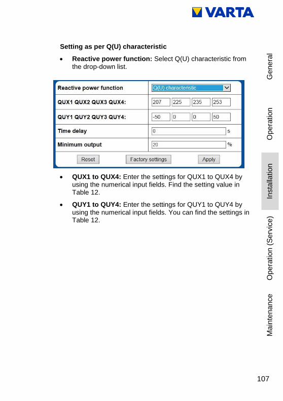
107
Ge
ne
ral
Op
era
tio
n
Insta
llation
Op
era
tio
n (
Serv
ice
) M
ain
ten
ance
Setting as per Q(U) characteristic
Reactive power function: Select Q(U) characteristic from the drop-down list.
QUX1 to QUX4: Enter the settings for QUX1 to QUX4 by using the numerical input fields. Find the setting value in Table 12.
QUY1 to QUY4: Enter the settings for QUY1 to QUY4 by using the numerical input fields. You can find the settings in Table 12.

108
Parameter Meaning
QUX1
Start of the first section of the Q(U) characteristic
on the voltage axis. The parameter is entered in
V. Example: The characteristic begins at 190 V
the value of QUX1 is 190.
QUY1
Power factor at the start of the Q(U)
characteristic. If the grid voltage falls below the
value defined by QUX1, the characteristic is
limited to the value set in QUY1. The setting is to
be found in Table 10.
QUX2
End of the first section of the Q(U) characteristic
on the voltage axis. The parameter is entered in
V. Example: The first section of the characteristic
ends at 220 V the value of QUX2 is 220.
QUY2
Power factor at the end of the first section of the
Q(U) characteristic. If the grid voltage increases
beyond the value defined by QUX2, the
characteristic is limited to the value set in QUY2.
The setting is to be found in Table 10. Normally
the parameter is set to 0, i.e. no reactive power is
produced.
QUX3
Start of the second section of the Q(U)
characteristic on the voltage axis. The parameter
is entered in V. Example: The characteristic
begins at 235 V the value of QUX3 is 235.
QUY3
Power factor at the start of the Q(U)
characteristic. If the grid voltage falls below the
value defined by QUX3, the characteristic is
limited to the value set in QUY3. The setting is to
be found in Table 10. Normally, the parameter is
set to 0, i.e. no reactive power is produced.

109
Ge
ne
ral
Op
era
tio
n
Insta
llation
Op
era
tio
n (
Serv
ice
) M
ain
ten
ance
Parameter Meaning
QUX4
End of the second section of the Q(U)
characteristic on the voltage axis. The parameter
is entered in V. Example: The second section of
the characteristic ends at 240 V the value of
QUX4 is 240.
QUY4
Power factor at the end of the first section of the
Q(U) characteristic. If the grid voltage increases
beyond the value defined by QUX4, the
characteristic is limited to the value set in QUY4.
The setting is to be found in Table 10.
Table 12: Setting as per Q(U) characteristic
Figure 25: Q(U) characteristic

110
i
When setting the parameters, the following
condition must be adhered to:
QUX1 ≤ QUX2 < QUX3 ≤ QUX4
Time delay: Enter the time in s, after which the reactive power is to be adjusted.
Minimum power: Enter the minimum power in %, up to which the reactive current is not controlled.
9.5. Power limitation
If you need the power limitation P(U) (TOR D4), you can select either characteristic A or B via the drop down list.
9.6. Logging out
Finally, it is necessary to ensure that the customer is unable to access the password-protected area.
Click on the Logout tab.

111
Ge
ne
ral
Op
era
tio
n
Insta
llation
Op
era
tio
n (
Serv
ice
) M
ain
ten
ance
Maintenance
10. Maintenance basics
This section is intended for the qualified
electrician.
10.1. Safety instructions
DANGER
Contact with live parts!
Mortal danger.
Adhere to the waiting times.
Make sure that the battery modules are
switched off and no LED indicator is lit.
The energy storage system must not
be transported if a battery module has
already been installed.

112
Observe the safety rules!
Disconnect.
Lock out.
Check for absence of voltage.
Before connecting up the power supply, make sure that no persons are in the hazard zone.
WARNING
Improper execution of maintenance and cleaning work!
Possible mortal danger.
Only original parts are to be used for
maintenance work.
When all work is complete, cleanly
remake and check the contacts and
connections and screw in place.
All work on the VARTA pulse system
must be documented by the qualified
electrician in the service book.

113
Ge
ne
ral
Op
era
tio
n
Insta
llation
Op
era
tio
n (
Serv
ice
) M
ain
ten
ance
WARNING
Contact with sharp-edged parts!
Cut injuries.
Wear your personal protective
equipment.
WARNING
Components are heavy!
This might lead to overburdened
intervertebral discs, bruises and crushing.
Carry out the work described in this
chapter with 2 persons or suitable
equipment.
10.2. Scope of maintenance work
Maintenance of the VARTA pulse energy storage system includes:
Service (= inspection and maintenance)
Repair and technical improvements and any additions
For documentation on the maintenance procedure, see Chapter 5. .
114
11. Service and repair work
This section is intended for the qualified electrician.
11.1. Inspecting the energy storage system from outside
Is the inlet opening for ventilation on the battery inverter blocked/clogged (see Chapter 11.4.6 )?
Is the temperature at the installation location between 5 °C and 45 °C assured throughout the year (+18 °C is the ideal temperature)?
Clarify with the customer as to how the temperature at the installation location can be maintained. If necessary, an active fan has to be installed.
Clarify with the customer whether any additional heat sources have been installed at the installation location since installation of the storage system or last maintenance.
Is the wall-mounting stable? Tighten or replace the screws as necessary.
11.2. Checking the system parameters (Service)
The system parameters are checked via the web interface. To do so, please observe Chapter 9.1. and the service booklet.
11.2.1 Checking the online status
On the web interface welcome page, the WWW icon indicates whether the energy storage system is connected to the VARTA server (green = online, red = offline).

115
Ge
ne
ral
Op
era
tio
n
Insta
llation
Op
era
tio
n (
Serv
ice
) M
ain
ten
ance
11.2.2 Error lists
Reading out error lists
Select the System button from the header.
The error lists for the storage system and the grid and system (GS) protection will be displayed.
Error rectification
Identify the errors using the error descriptions.
Check above all whether there are any temperature errors in the error list (error text with leading T…). This provides an indication of the maintenance that needs to be carried out (fan and ventilation openings) as well as improper ambient conditions.
Notes on troubleshooting can also be found in the overviews Battery module and Battery inverter. Over there, check the categories status, faults, as well as control WR, control EMS and control ENS.
Check the GS settings, if necessary (see Chapter 9.4.4 ) and eliminate the error.
Then restart the energy storage system. Turn the storage system off and then back on again at the On/Off button after waiting approx. 30 seconds.
If the errors cannot be rectified, notify VARTA Service.
Error list NA error list
No errors No NA errors

116
In case of storage systems operated offline, click on the Report button and send the report to VARTA Service.
Serial numbers oft the battery modules
EM048126P3S7BMA17031708023
11.2.3 Checking the software version
Select the Version tab from the header.
The software versions can be read.
OVERVIEW OF THE VERSION
No. Serial Mac
SW
ID
HW
ID
SW
Version
BL
Version
WR K593166 534A5D 11 FF C11000124 1.3.0.3
EMS 00295F - 15 FF C21000132 -
DCEN zFFFFFF 4DFBFF A0 FF C31000303 3.0.4
EM M378336 0CC200 - 7 C41000115 x.1.0.2
StateCheck
Report

117
Ge
ne
ral
Op
era
tio
n
Insta
llation
Op
era
tio
n (
Serv
ice
) M
ain
ten
ance
11.2.4 Software update
A software update is required if the energy storage system is operated offline or if an "Online Service by VARTA Storage" agreement has been concluded.
The software update can be carried out by using the VARTA network configurator (NCT). This is available for download in the B2B area of the page https://www.varta-storage.com after entering the username and the personal password.
i
Before you carry out a software update, please
check whether any errors are displayed on the
web interface. If yes, rectify them first and
restart. After this, the system is ready for a
software update
11.2.5 Air filter change: Resetting the time
The air filter must be replaced at every second service. See Chapter 11.4.6
From the Settings tab, select the Service settings item.
Check the Reset air filter box.
Click on Apply.

118
11.2.6 Checking the fan
From the Settings tab, select the Service settings item.
Use Manual fan control to toggle between settings 0 (= automatic), 1 (= medium setting) and 2 (= highest setting).
Check whether the fan is blowing out air at the top right and on the side. Wait for 10 to 15 s until the fan has reached a constant speed.
Note: It is possible that the fans are already running.
Pay attention to noises that indicate mechanical damage.
Reset to the Automatic (0) setting.
<
<

119
Ge
ne
ral
Op
era
tio
n
Insta
llation
Op
era
tio
n (
Serv
ice
) M
ain
ten
ance
11.3. Checking the system parameters
The system parameters are checked via the web interface. To do so, please observe Chapter 9.1.
11.3.1 Checking the current sensor values
Select the System page.
Check whether the current sensor values (I grid L1, I grid L2 and I grid L3) are realistic.
If a current sensor value is approx. 0, although the phase is currently loaded, the connection between current sensor and energy storage system might be faulty. If necessary, load all phases separately:
Switch on consumers deliberately.
If necessary, check the current through all three phases with the clamp-on ammeter!
Measures in case of suspicious current sensor values:
Check whether the connection corresponds to a clockwise phase sequence.
If the current sensor value of one or several phases is 0 in spite of a load, check the connection between energy storage system and current sensor. If necessary, replace the connecting cable (RJ12 cable).
OVERVIEW BATTERY INVERTER
L1 L2 L3
I Grid -6,82 A -0,15 A -2,36 A
I PV 0.14 A -0.05 A 0.13 A
Sensor Phase Phase 1
U Inv 0 V
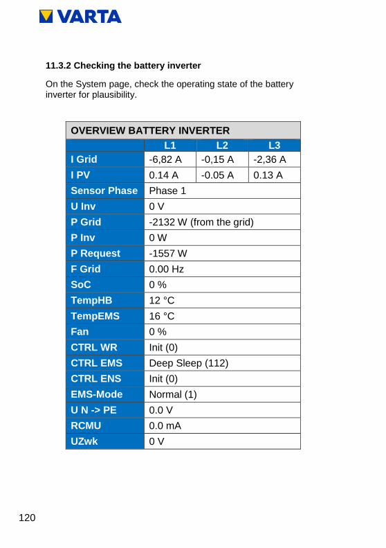
120
11.3.2 Checking the battery inverter
On the System page, check the operating state of the battery inverter for plausibility.
OVERVIEW BATTERY INVERTER
L1 L2 L3
I Grid -6,82 A -0,15 A -2,36 A
I PV 0.14 A -0.05 A 0.13 A
Sensor Phase Phase 1
U Inv 0 V
P Grid -2132 W (from the grid)
P Inv 0 W
P Request -1557 W
F Grid 0.00 Hz
SoC 0 %
TempHB 12 °C
TempEMS 16 °C
Fan 0 %
CTRL WR Init (0)
CTRL EMS Deep Sleep (112)
CTRL ENS Init (0)
EMS-Mode Normal (1)
U N -> PE 0.0 V
RCMU 0.0 mA
UZwk 0 V

121
Ge
ne
ral
Op
era
tio
n
Insta
llation
Op
era
tio
n (
Serv
ice
) M
ain
ten
ance
11.3.3 Checking the battery module
The warnings and errors regarding the battery module are displayed on the System page. Indicated errors are explained in the error list (see Chapter 11.2.2 ).
OVERVIEW BATTERY MODULE
SerNr UBatt IBatt PIst PSoll SoC zFFFFFF 48.39 V 0.00 A 0 W 0 W 0 %
OVERVIEW BATTERY MODULE
UZwk UVcc THT TTR TBoard Status 0 V 0.0 V 0 °C 0 °C 0 °C Off
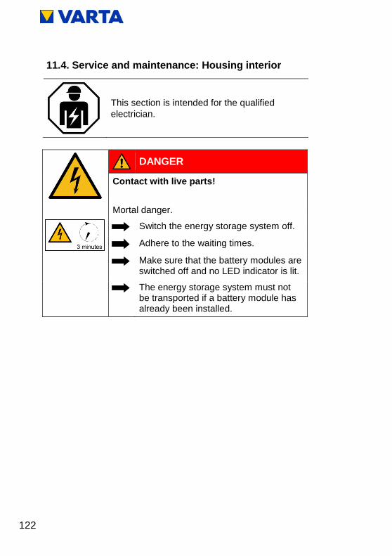
122
11.4. Service and maintenance: Housing interior
This section is intended for the qualified
electrician.
DANGER
Contact with live parts!
Mortal danger.
Switch the energy storage system off.
Adhere to the waiting times.
Make sure that the battery modules are switched off and no LED indicator is lit.
The energy storage system must not be transported if a battery module has already been installed.

123
Ge
ne
ral
Op
era
tio
n
Insta
llation
Op
era
tio
n (
Serv
ice
) M
ain
ten
ance
Observe the safety rules!
Disconnect.
Lock out.
Check for absence of voltage.
Before connecting up the power supply, make sure that no persons are in the hazard zone.
WARNING
Components are heavy!
This might lead to overburdened
intervertebral discs, bruises and crushing.
Carry out the work described in this
chapter with 2 persons or suitable
equipment.

124
11.4.1 Opening the energy storage system
Make sure that the On/Off button on the front of the housing is set to "Off" (= not depressed).
Remove the screws from the bottom of the hood to open the energy storage system.
Aid: Torx 20 screwdriver
Pull the bottom of the hood away from the wall (approx. 30 cm).
Figure 27: Latch on the earthing connector
Figure 26: Opening the energy storage system

125
Ge
ne
ral
Op
era
tio
n
Insta
llation
Op
era
tio
n (
Serv
ice
) M
ain
ten
ance
Disconnect the earthing connection between the hood and battery inverter. This requires opening the latch.
Lift off the hood (up).
Removing the battery inverter
Disconnect the electrical connections
Make sure no LEDs are lit on the battery module.
Loosen the screws 1-3
Lift the battery inverter up and out of the holder as shown (4).
i Make sure that no small parts drop into the battery
inverter.
Figure 28: Loosening the screws on the battery inverter

126
AC connection area
1 Micro-SD card slot
2 LAN
3 PV sensor (optional)
4 Grid sensor
5 AC grid
6 Main earth (PE) (2x)
Figure 29: Battery inverter sockets (bottom

127
Ge
ne
ral
Op
era
tio
n
Insta
llation
Op
era
tio
n (
Serv
ice
) M
ain
ten
ance
11.4.2 Installing the battery inverter
To reinstall, perform the working steps in reverse order. The battery inverter stops at the end position.
DC connection area
1 Air outlet
2 Batt (battery module)
3 Fan
4 CAN
5 DRY
Figure 30: Connections on the battery inverter (top)

128
11.4.3 Removing and installing the battery module
WARNING
Improper handling of the battery module!
Personal injuries and material damage.
Do not damage the battery module
during removal and installation.
Do not attempt to repair it.
Battery modules are maintenance-free
and must not be opened under any
circumstances.
Make sure that the battery modules are
switched off and no LED indicator is lit.

129
Ge
ne
ral
Op
era
tio
n
Insta
llation
Op
era
tio
n (
Serv
ice
) M
ain
ten
ance
11.4.4 Removing the battery module
WARNING
Improper handling of the battery module!
Personal injury and material damage.
Carry out the work described in this
chapter with 2 persons or suitable
equipment.
Do not lift the battery module by the
handle.
Use the handle to guide the battery
module during installation.
ATTENTION
Improper disconnection of the cables!
Damage to the connectors.
Press the latch on the connector; then
carefully pull the connector upwards.
Make sure that the battery module
is switched off and no LED indicator is lit.

130
If the battery module has not switched off automatically:
Switch off the battery module at the activation button (hold the button, until the LED goes off).
Then disconnect the following wires:
o Connections for battery current
o DRY contact
o CAN
Loosen the four mounting screws, see: Figure 31: Battery module fastening screws.
Lift the battery module off the mounting rails.
Figure 31: Battery module fastening screws
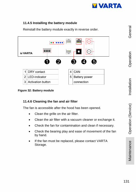
131
Ge
ne
ral
Op
era
tio
n
Insta
llation
Op
era
tio
n (
Serv
ice
) M
ain
ten
ance
11.4.5 Installing the battery module
Reinstall the battery module exactly in reverse order.
11.4.6 Cleaning the fan and air filter
The fan is accessible after the hood has been opened.
Clean the grille on the air filter.
Clean the air filter with a vacuum cleaner or exchange it.
Check the fan for contamination and clean if necessary.
Check the bearing play and ease of movement of the fan by hand.
If the fan must be replaced, please contact VARTA Storage.
Figure 32: Battery module

132
11.4.7 Exchanging SD Card
Removing SD Card
You can find the SD card in the connection area AC, position 1.
Preparing SD Card
Before inserting the new SD card into the battery inverter, you still have to prepare this.
I. To do so, insert the new SD card into a notebook, a computer or into a card reader connected to the computer.
Figure 33: Position of the SD card
We recommend using a new SD card. If there is data on the
SD card you have chosen, make a backup of this first.
Afterwards, format the SD card in FAT32 format.
133
Ge
ne
ral
Op
era
tio
n
Insta
llation
Op
era
tio
n (
Serv
ice
) M
ain
ten
ance
II. Download the "RES-Webserver-X.X.X.X.zip" file in the VARTA B2B area under downloads and unpack the contained "http" folder.
III. Copy the unpacked "http" folder to the SD card.
Installing SD card
I. Insert the prepared SD card into the battery inverter.
II. Close the slot again so that no unwanted air is sucked in.
After installing the SD card, you can restart the energy storage system as described in the instruction manual.
The entire "http" folder together with all files must be
present on the SD card.

134
11.5. Completion of service and repair work
DANGER
Contact with live parts!
Mortal danger.
Remove all tools and/or small parts
from the interior.
Establish all cable connections
correctly.
Check all cable ducts.
Check all safety devices.
No persons in the hazard zone before
connecting up the power supply.
ATTENTION
On/Off switch could be damaged!
System cannot be put into operation.
Do not use any force when closing the
hood.
The switch must fit in the opening in
the battery inverter.
Before you close the energy storage system, please check:
is the interior clean?
edge protection installed at the intended locations?
Make any necessary corrections.

135
Ge
ne
ral
Op
era
tio
n
Insta
llation
Op
era
tio
n (
Serv
ice
) M
ain
ten
ance
If everything is all right, then:
place the hood over the mounting plate at an angle of 45°,
lower the hood carefully until it rests against the back of the mounting plate,
connect the earth cable between the hood and battery inverter,
check the electrical connection between the hood and central earthing point by means of a continuity test,
swivel the hood towards the unit while paying attention to the position of the On/Off switch
o Make sure that no cables are pinched!
o The spring must engage audibly!
secure the energy storage system with the three supplied screws on the bottom.
11.5.1 Checking the operating state
Check whether the fuses have been re-connected.
Switch on the energy storage system using the On/Off button. The button will be locked in the lower position.
Figure 34: On/Off button with LED ring

136
Check whether the LED ring indicates the following operating states after the unit is switched on:
If necessary, check whether error messages appear on the web interface (see Chapters 4.3.2 and 9.2. ) and rectify the errors if possible.
Check the fan for proper operation (see Chapter 11.2.6 ).
If the battery module was exchanged, enter the serial number of the module on the Web interface (see Chapter 8.13.3 ).
LED ring colour
LED action Operating state
Green
Flashes every
second
(approx. 90 s)
System check
Green
Steady light Ready
Green
Flashes every 3 s Standby
Green
Pulses with
increasing intensity Charge
Green
Pulses with
decreasing intensity Discharge

137
Ge
ne
ral
Op
era
tio
n
Insta
llation
Op
era
tio
n (
Serv
ice
) M
ain
ten
ance
11.5.2 Cleaning
WARNING
Entry of water into electrical systems!
Possible mortal danger.
Do not use water for cleaning the
energy storage system.
Never put down containers with fluids
(beverage containers and the like) on
electrical systems.
Cleaning agents
Do not use any cleaning agents containing acid, lye or
solvents!
Cleaning the outside of the housing
clean with a vacuum cleaner.
wipe with a damp, not wet, cloth.

138
12. Malfunctions
WARNING
Improper troubleshooting due to lack of professional knowledge!
Personal injuries and material damage.
Only the qualified electrician is allowed
to rectify malfunctions.
12.1. Malfunction indicators of the LED ring
The LED ring at the On/Off switch indicates malfunctions. See Table 9.
12.2. Malfunction indicators on the web interface
Malfunctions are displayed on the System page of the web interface.
Select the System tab from the header.
The error lists for the storage system and the grid and system (GS) protection can be read out.

139
Ge
ne
ral
Op
era
tio
n
Insta
llation
Op
era
tio
n (
Serv
ice
) M
ain
ten
ance
13. Disassembly and disposal
13.1. Planning disassembly
WARNING
Improper disassembly due to lack of professional knowledge!
Personal injuries and environmental damage.
Only the qualified electrician is allowed
to disassemble the energy storage
system.
Read the instruction manual.
i If the original packaging is no longer
available, request suitable packaging for
hazardous goods.
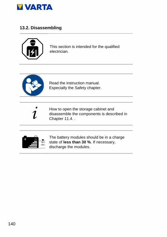
140
13.2. Disassembling
This section is intended for the qualified
electrician.
Read the instruction manual.
Especially the Safety chapter.
i How to open the storage cabinet and
disassemble the components is described in
Chapter 11.4. .
The battery modules should be in a charge
state of less than 30 %. If necessary,
discharge the modules.

141
Ge
ne
ral
Op
era
tio
n
Insta
llation
Op
era
tio
n (
Serv
ice
) M
ain
ten
ance
13.3. Disposal
i The packed battery modules will be collected by
VARTA Storage or by a company assigned by
them. For this purpose, please contact VARTA
Storage ([email protected]). If
necessary, also request packaging for hazardous
goods. Packaging and collection costs are taken
over by VARTA Storage.
The cabinet can be disposed of as electrical waste, for
instance at a recycling centre.
The VARTA pulse system must not be
disposed of via domestic waste.

142
14. Relocation
14.4. Planning a relocation
WARNING
Improper disassembly due to lack of professional knowledge!
Personal injuries and environmental damage.
Only the qualified electrician is allowed
to disassemble the energy storage
system.
Read the instruction manual.
i If the original packaging is no longer available,
request suitable packaging for hazardous goods.

143
Ge
ne
ral
Op
era
tio
n
Insta
llation
Op
era
tio
n (
Serv
ice
) M
ain
ten
ance
14.5. Relocating
This section is intended for the qualified
electrician.
WARNING
Improper transport due to lack of professional knowledge!
Possible mortal danger and material damage.
The transportation of the energy storage
system and its components is only
allowed to be carried out by the
manufacturer and the electricians
qualified and certified by him.
Be prudent during transport.
Adhere to the transportation regulations.
Read the instruction manual.

144
i How to open the storage cabinet and
disassemble the components is described in
Chapter 11.4. .
The battery modules should be in a charge
state of 20 to 30 % of their capacity.
If necessary, charge or discharge the battery
modules.
The battery modules must be commissioned
again by a qualified electrician certified by
VARTA Storage within 11 weeks after
removal.
Conformity with the relevant EU Directives for the device is verified by the CE mark.
Declaration of Conformity (DoC)
The components used have been developed and manufactured in compliance with applicable Directives and Standards. The complete Declaration of Conformity is available on our Internet page: www.varta-storage.com.
This instruction manual is not to be construed as a contract. Subject to errors, printing mistakes and modifications.

145
Figures
Figure 1: Front view ....................................................................... 19 Figure 2: System overview ............................................................ 20 Figure 3: Rating plate (example) ................................................... 21 Figure 4: On/Off button with LED ring ........................................... 27 Figure 5: Web interface: Welcome page ....................................... 30 Figure 6: Example of ID label for the system (in the hood) ........... 48 Figure 7: ID label of the battery module (example) ....................... 48 Figure 8: Activation code label (example) ..................................... 49 Figure 9: Stripping cables .............................................................. 61 Figure 10: AC connector ................................................................ 62 Figure 11: AC connector with strain relief ..................................... 62 Figure 12: VARTA Split Core current sensor (Single Phase) ........ 65 Figure 13: VARTA Split Core current sensor (Three Phase) ........ 65 Figure 14: Dimensions on mounting plate (mm) ........................... 70 Figure 15: Battery inverter sockets (bottom) ................................. 71 Figure 16: VARTA pulse battery module ....................................... 75 Figure 17: Battery module terminals (DRY contact) ...................... 76 Figure 18: Battery module fastening screws ................................. 77 Figure 19: Internal connections ..................................................... 77 Figure 20: Hood fastening screws ................................................. 80 Figure 21: On/Off button ................................................................ 81 Figure 22: Checking the welcome page on the web interface ...... 90 Figure 23: Info window on the web interface ................................. 91 Figure 24: Q(P) characteristic...................................................... 105 Figure 25: Q(U) characteristic ..................................................... 109 Figure 26: Opening the energy storage system .......................... 124 Figure 27: Latch on the earthing connector................................. 124 Figure 28: Loosening the screws on the battery inverter ............ 125 Figure 29: Battery inverter sockets (bottom ................................ 126 Figure 30: Connections on the battery inverter (top) ................... 127 Figure 31: Battery module fastening screws ............................... 130 Figure 32: Battery module ........................................................... 131 Figure 33: Position of the SD card .............................................. 132 Figure 34: On/Off button with LED ring ....................................... 135

146
Tables
Table 1: Safety instructions .............................................................. 3 Table 2: Warning levels .................................................................... 4 Table 3: Safety signs ........................................................................ 5 Table 4: Warning signs..................................................................... 6 Table 5: Technical parameters - VARTA pulse 3 ........................... 22 Table 6: Technical parameters - VARTA pulse 6 ........................... 23 Table 7: Technical parameters – battery modules ......................... 24 Table 8: Technical parameters – environmental rating data .......... 25 Table 9: LED ring indications at the On/Off button ........................ 28 Table 10: Grid parameter default settings .................................... 102 Table 11: Setting as per Q(P) characteristic ................................ 106 Table 12: Setting as per Q(U) characteristic ................................ 109
Appendix
Appendix 1: Connection diagram of TT system
Appendix 2: Connection diagram of TT system with data logger
Appendix 3: Connection diagram of TN-C system
Appendix 4: Connection diagram of TN-C system with data logger