H-Bridges Motor Drivers - NXP...
60
External Use TM H-Bridges Motor Drivers FTF-IND-F0332 MAY.2014 Sanyuan Ruan | System and Application Engineer Tom Zemites | Product Line Manager Pramit Nandy | System and Applications Engineer
Transcript of H-Bridges Motor Drivers - NXP...
External Use
TM
H-Bridges Motor Drivers
FTF-IND-F0332
M A Y . 2 0 1 4
Sanyuan Ruan | System and Application Engineer
Tom Zemites | Product Line Manager
Pramit Nandy | System and Applications Engineer

TM
External Use 1
Agenda
Overview of Freescale Analog Driver Group and Introduction to H-Bridge Product Portfolio (5 minutes)
Technology Review (5 minutes)
Motor Driver Basics (10 minutes)
Application Examples (10 minutes)
Portfolio Review (10 minutes)
Power Dissipation and Thermal Analysis (5 minutes)
Integration and Demonstration with FRDM Platform (10 minutes)
Wrap-up and Enablements (5 minutes)

TM
External Use 2
Freescale Analog
Analog Organization and Driver Products
Expanding Markets

TM
External Use 3
Microcontrollers and Digital Networking Processors
A Global Leader in
Five Core Product
Groups
Four Primary
Markets
Microcontrollers
Digital Networking
Automotive MCU
Analog & Sensors
RF
Automotive
Networking
Industrial
Consumer
• 50 Year Legacy
• 5,500 Engineers
• 6,100 Patent Families

TM
External Use 4
Analog & Sensor Group Organizational Chart
Deena Shipman Executive Assistant
Babak Taheri
Sensor
Solutions
Corporate Support
Brett Whitmire
Finance
Marc Paul Denamiel
HR
James Trimble
Legal
Bob Sulski
Quality
Jill Partridge
Communications
James Bates SVP & GM
Erwan Hemon
Design and Test
Eric Toulouse
Driver
Products
Jaime Pla
Power
Products
Patrick Morgan
Safety
Systems
Jorge Salhuana
Standard
Products
Mark Klatt
Product Engineering
Ronen Shtayer
Program Mgmt & Technology Development
Lisa Bradley
Corporate Marketing
Joe Bruen
Business
Operations
Rick Beale
Marketing &
Strategy
Product Team Support

TM
External Use 5
Freescale Analog in the World
Tempe, AZ - Design & Eng - Fab - Operations
Detroit, MI Design
Austin, TX
- Fab*2
Toulouse, France - Design & Eng - Operations
Moscow Design
Tianjin, China - Manufacturing - Operations
Korea ASM - Manufacturing

TM
External Use 6
Analog Drivers: High Level Portfolio
Product Type Market / Typical Application
H-Bridge
Automotive (engine management, throttle control, electronic gas
recirculation, turbo flap control, etc.)
Industrial (DC brushed & stepper motor)
Consumer (battery operated system)
3 Phase Gate Driver
Automotive (EPS, EGR, ETC, HVAC)
Industrial (fans, pumps, power tools, and general brushless DC motor
drive)
General Purpose Low Side
and High Side drivers
Automotive (engine management, body)
Industrial (general purpose load driver)
Solenoid Drivers & Controllers Automotive (engine control, transmission)
Industrial (small engine control, solenoid driver)
Networked Motor Driver Automotive (body electronic)
Industrial (gas valves, motor valves control)

TM
External Use 7
SMARTMOS Technology for Today and Tomorrow
SMOS Roadmap

TM
External Use 8
SMARTMOS™
MOS-Analog ICS
SMARTMOS Technology Integration
More than driving loads
• Cost-effective high voltage (105V) power analog embedded system process platform
• Low RDS(ON)*A (30 mΩ-mm2) for thermal efficiency in high current applications
• High precision for sensor interface integrated with power applications
• Advanced isolation capability (-40V) and robust system transient ESD/EMC immunity
• Low power devices to reduce overall system power consumption
• Extreme temperature operation for harsh application environments (-40ºC to +175ºC)
TM
External Use 9
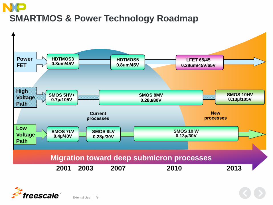
Migration toward deep submicron processes
2001 2003 2007 2010 2013
Migration toward deep submicron processes
Low
Voltage
Path
SMOS 7LV 0.4µ/40V
SMOS 8LV 0.28µ/30V
SMOS 10 W 0.13µ/30V
Current processes
High
Voltage
Path
SMOS 5HV+ 0.7µ/105V
SMOS 8MV 0.28µ/80V
SMOS 10HV 0.13µ/105V
Power
FET
HDTMOS3 0.8um/45V
HDTMOS5 0.8um/45V
New processes
LFET 65/45
0.28um/45V/65V
SMARTMOS & Power Technology Roadmap

TM
External Use 10
SMOS5HVP
2002
SMOS8MV
2003
SMOS5AP
1996 (0.8 µm)
SMOS10HV
2013 (0.13 µm)
Logic
Density
Voltage
Capability
45V Power
Rdson*A
Isolation
Voltage
1.1K 2.0K 25.0K 90.0K
65V 105V 45/80V 105 V
40 mW·mm² 30 mW·mm² 67 mW·mm² 90 mW·mm²
80 V
(Trench)
105 V
(Trench + SOI)
SMOS5HVP
2002 (0.7 µm) SMOS8MV
2006 (0.25 µm)
105 V
(Junction) 65 V
(Junction)
LVN NW
LVN o
HVNW
N+ N+
LVN P+ N+
LVN STI P+ P+ N+ P+ N+ STI N+ N+ Dee
p
Tre
nch
T
r
e
n
c
h
STI
T
r
e
n
c
h
P+ P+ STI N+ N+ P+ STI STI
T
r
e
n
c
h
SMARTMOS Evolution

TM
External Use 11
Motor Driver Basics DC Brushed and Stepper Motor Driver review
Basic operation
Internal architecture

TM
External Use 12
H-Bridge DC Brushed and Stepper Motor Drivers
Basic Operation With Brushed DC Motor
Several types of motors
• 3-phase AC, brushless AC, DC brushed,
stepper, etc.
• This presentation focus is on DC brushed
and stepper motor
Important considerations for motor drivers
• Number of outputs
• Voltage & current operation range; will vary
depending on load (motor)
• Low resistance path
• Switching frequency; trade-off between
noise and efficiency
Freescale integrates analog and digital an
power MOSFETs into a turnkey solution
An H-bridge is an electronic circuit
that enables a voltage to be applied
across a load in either direction.
HS1 HS2
LS1 LS2
ON
ON
ON
ON
Forward Reverse

TM
External Use 13
H-Bridge DC Brushed and Stepper Motor Drivers Basic Operation With Stepper Motor
HS1 HS2
LS1 LS2
ON
ON
ON
ON
HS1 HS2
LS1 LS2
ON
ON
ON
ON
• Dual H-Bridge required for stepper motor control
• Requires sequentially switched power

TM
External Use 14
DC Brushed and Stepper Motor Driver Control
Example H-Bridge Pin-out
• Inputs - typically from micro or PWM
• Outputs - motor control
• Enable
• Disable
• Status flag for errors OV, OC, UV, etc
• Current mirror output
• Powers
• Grounds
Example Dual H-Bridge Pin-out
• Dual input control from micro
• Dual output motor control
• Pin-out for external capacitors for charge pumps
• Powers
• Grounds
TM
External Use 15
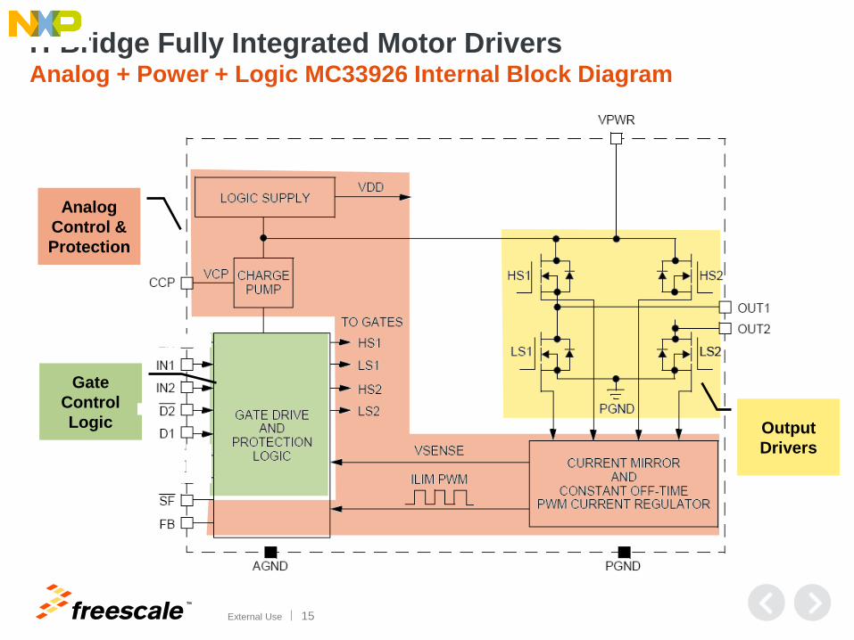
H-Bridge Fully Integrated Motor Drivers Analog + Power + Logic MC33926 Internal Block Diagram
Analog
Control &
Protection
Output
Drivers
Gate
Control
Logic EN/

TM
External Use 16
Application Examples DC Brushed and Stepper Motor Portfolio for Battery, 5V and 12V Bus
Review of device portfolio
One pagers of device features and benefits

TM
External Use 17
Portable Point of Sale Terminal
M
CPU:
i.MX25
i.MX7
6 DC/DC
PF0100
6 LDO I²C
OTP
5.0V
3.3V
2.5V
1.5V
Vdd
Charge
Pump
Control &
Monitoring
MPC17531
Vbatt
MPC17531 1.4A Dual
H-Bridge Driver IC
Protection
HS1
LS1
HS2
LS2
HS1
LS1
HS2
LS2
Paper handling
stepper motors
Connectors,
System
Wireless Module
Audio
Display
Logic
Control
Charge
Control
MC34675
Vin
Monit
or
Power
Source
MC34675 LiOn
battery charger IC
3.6V
Li-ion
battery
Vbatt

TM
External Use 18
Brushed DC Motor Control Application (12-24V)
MC34903
2 LDO Safety
SPI
12 or 24 V
5V Watch-dog
Reset
CAN
CAN
Charge
Pump
Control &
Monitoring
MC34931
12 or 24 V
SPI
MC34903 Power Management
and Safety System IC
MC34931 5A
H-Bridge Driver IC
Applications: Tube motor, cash counter, electric rolling door, robotics, medical, etc.
Protection
Cortex
M0+
core
PWM
ADC
Kinetis E
Kinetis E
Robust 5V MCU
M
HS1
LS1
HS2
LS2

TM
External Use 19
Battery Powered UPS Inverter
Applications: Home or office battery back-up uninterruptible power supply (UPS),
stationary and grid storage battery, battery powered vehicle
MC34903
2
LDO Safety
SPI
DSC
core PWM
ADC
MC56F84xxx
12 V
3.3V Watchdog
reset
CAN
CAN
Co
ntro
l
Charge
Pump
HS
drivers
MC33883
12 V
SPI
MCU
V, I, temp
sense
MM912J637
Sigma
Delta
ADC
12 V
SPI
AC
voltage
MC34903 Power Management
and Safety System IC
MC33883 H-bridge
gate driver IC
MC912J637 battery
sensor for 12V lead acid
MC56F84xxx Digital
Signal Controller MCU
12V
Pb
LS
drivers
110 /
220V
H External
MOSFET
H-bridge 14V
To 48V
LiOn MM9Z1J638
or

TM
External Use 20
Brushed DC Motor Control Application (3.6V Li-ion or 5V)
Applications: Digital camera, video conference, DVD player, small robots, toys, etc.
Cortex
M0+
core
PWM1
PWM2
Kinetis E
Kinetis E
Robust 5V MCU
M
Charge
Pump
Vcc Detect
Thermal
Detection
MC34933
Vbatt or 5V
MC34933 1A dual
H-bridge driver IC
Control
Logic
HS1
LS1
HS2
LS2
HS1
LS1
HS2
LS2
Stepper
motor
Logic
Control
Charge
Control
MC34674
Vin
Monitor
DC Power Source
(Wall charger, USB, etc.)
MC34674 LiOn
battery charger IC
3.6V
Li-ion
battery
Vbatt or 5V

TM
External Use 21
Multi Function Printer
M
CPU:
i.MX6
LS1021
6 DC/DC
PF0100
6 LDO I²C
OTP
5.0V
3.3V
2.5V
1.5V
Vdd Vcc
Charge
Pump
Control &
Monitoring
MC34932
12 or 24 V
MC34932 5A dual
H-bridge driver IC
Protection
HS1
LS1
HS2
LS2
HS1
LS1
HS2
LS2
Paper handling
stepper motors
Control
Vpower
Load
Protection,
Diagnostic
MC34981 24 V
MC34972 switch
monitoring IC
Printer
Head
MC34972
Memory
DDR
SPI Switch
Control Up to 22 switches
SPI
MC34981 low RDSon high
side switch
Connectors,
System

TM
External Use 22
IMM H-Bridge Design: Win and Opportunities
MPC17510 LV H-Bridge Stepper
Motor Driver
MC33926 MV H-Bridge Motor
Driver
WIN
• Simple interface
• 1.2A, small package
WIN
• Self protected for
continuous operation
OPPORTUNITY
• Safety features
• Sleep mode
PTZ Camera adjust
Postal Kiosk
Tube Motor Shades
MC34931 MV H-Bridge Motor
Driver
MPC17511 LV H-Bridge Stepper
Motor Driver
MPC17C724 LV H-Bridge Motor
Driver
WIN
• Integration
OPPORTUNITY
• Integration
Medicine auto-injector
Electric Shaver
TM
External Use 23
Low Voltage Portfolio DC Brushed and Stepper Motor Portfolio for Battery, 5V and 12V Bus
Review of device portfolio
One pagers of device features and benefits

TM
External Use 24
Low Voltage Motor Driver Selector Guide
Targeting Battery / 5 V / 12V Bus Applications
Base Part # Motor type Out
Operation
Voltage
(V)
Peak
Current
(A)
LL
(V)
Sleep
(µA)
Freq
(kHz)
Temp
Range (°C)
Package
(LxW mm)
Footprint
MPC17510EJ Brushed DC /
Actuator Drive 2+1 2.0-15 3.8 4.0-5.5 - 200 -30 to 65
TSSOPW 24
(7.8 x 7.6)
MPC17511EP Brushed DC /
Actuator Drive 2+1 2.0-6.8 3.0 2.7-5.7 - 200 -20 to 65
QFN 24
(4 x 4)
MPC17511EV Brushed DC /
Actuator Drive 2+1 2.0-6.8 3.0 2.7-5.7 - 200 -20 to 65
SOIC 16
(5.4 x 8.1)
MC34933EP Stepper /
Brushed DC 4 2.0-7.0 1.4 2.7-5.5 - 200 -20 to 85
QFN 16
(3 x3)
MPC17529EV Stepper /
Brushed DC 4 2.0-6.8 1.4 2.7-5.6 - 200 -20 to 65
SOIC 20
(7.4 x 8.1)
MPC17531ATEV Stepper /
Brushed DC 4 2.0-8.6 1.4 2.7-3.6 2 200
-20 to 65
SOIC 20
(7.4 x 8.1)
MPC17531ATEP Stepper /
Brushed DC 4 2.0-8.6 1.4 2.7-3.6 2 200 -20 to 65
QFN 24
(4 x 4)
MPC17533EV Stepper /
Brushed DC 4 2.0-6.8 1.4 2.7-5.7 - 200 -20 to 65
SOIC 16
(5.4 x 8.1)
MPC17C724EP Stepper /
Brushed DC 4 2.7-5.5 0.8 2.7-5.5 1 200 -20 to 85
QFN 16
(3 x 3)

TM
External Use 25
H-Bridge DC Motor Drivers
Features Benefits
Four operation modes Provides control in forward, reverse, braking and tri-state for
safe shut-down
200 kHz Pulse Width Modulation frequency capable High slew rates provide ability to program high resolution
micro-stepping and efficiency to drive micro-motors
TSWITCH output for driving an external MOSFET Integrated high side driver decreases part count
Offer in 3X3 mm QFN package (MC34933 &
MPC17C724) Ultra-small footprint for small and portable applications
Built-in shoot through current and under-voltage
protection Increases safety and reliability
Higher current outputs (0.8 to 3.8 Amps peak) Low RDS(ON)
Offering 2 and 4 outputs H-bridge For driving either DC brushed or stepper motors
Sleep mode with < 1 μA current draw (MPC17C724) Reduced power consumption, especially for battery
applications
TM
External Use 26
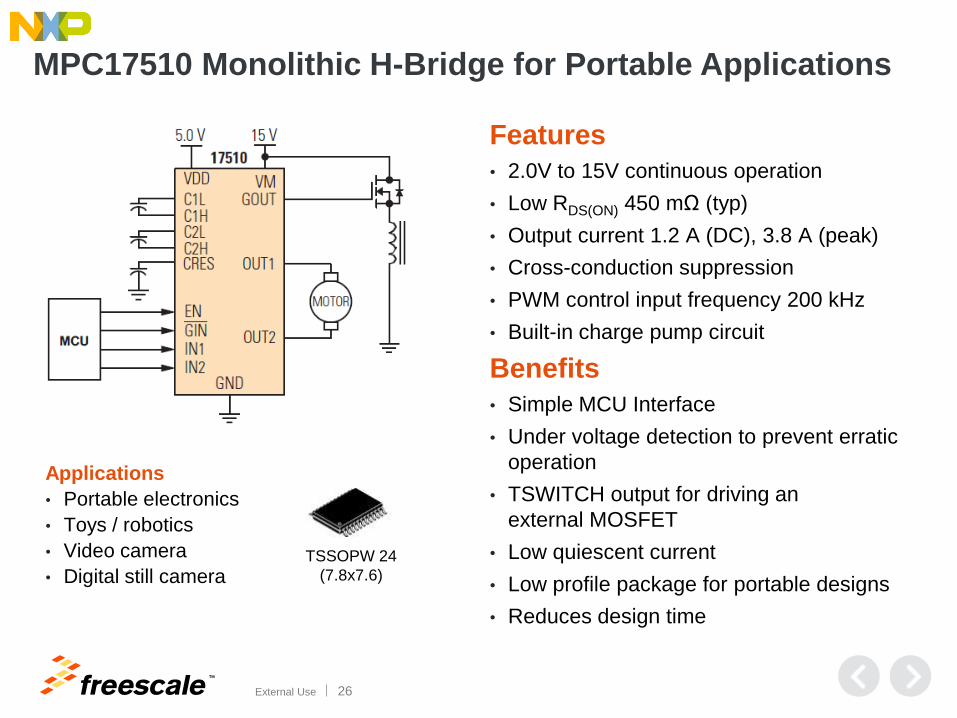
MPC17510 Monolithic H-Bridge for Portable Applications
Features
• 2.0V to 15V continuous operation
• Low RDS(ON) 450 mΩ (typ)
• Output current 1.2 A (DC), 3.8 A (peak)
• Cross-conduction suppression
• PWM control input frequency 200 kHz
• Built-in charge pump circuit
Benefits
• Simple MCU Interface
• Under voltage detection to prevent erratic
operation
• TSWITCH output for driving an
external MOSFET
• Low quiescent current
• Low profile package for portable designs
• Reduces design time
TSSOPW 24
(7.8x7.6)
Applications
• Portable electronics
• Toys / robotics
• Video camera
• Digital still camera

TM
External Use 27
MPC17511 Monolithic H-Bridge for Portable Applications
Features
• 2.0V to 6.8V continuous operation
• Low RDS(ON) 460 mΩ (typ)
• Output current 1.0 A (DC), 3.0 A (peak)
• 3.0V/5.0V TTL-/CMOS-compatible inputs
• Shoot-through current protection circuit
• PWM control input frequency 200 kHz
• Built-in charge pump circuit
Benefits
• Simple MCU interface
• Under voltage detection to prevent erratic
operation
• TSWITCH output for driving an external
MOSFET
• Low quiescent current
• Low profile package for portable designs
• Reduces design time
Applications
• Portable electronics
• Toys / robotics
• Video camera
• Digital still camera
QFN 24
(4x4) SOIC 16
(5.4x8.1)
TM
External Use 28
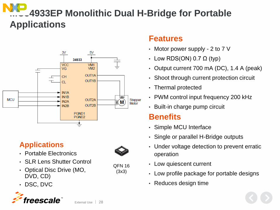
MC34933EP Monolithic Dual H-Bridge for Portable
Applications
Features • Motor power supply - 2 to 7 V
• Low RDS(ON) 0.7 Ω (typ)
• Output current 700 mA (DC), 1.4 A (peak)
• Shoot through current protection circuit
• Thermal protected
• PWM control input frequency 200 kHz
• Built-in charge pump circuit
Benefits • Simple MCU Interface
• Single or parallel H-Bridge outputs
• Under voltage detection to prevent erratic
operation
• Low quiescent current
• Low profile package for portable designs
• Reduces design time
Applications • Portable Electronics
• SLR Lens Shutter Control
• Optical Disc Drive (MO, DVD, CD)
• DSC, DVC
QFN 16
(3x3)

TM
External Use 29
MPC17529 Monolithic Dual H-Bridge for Portable Apps
Features
• Motor power supply - 2 to 6.8 V
• Low RDS(ON) 0.7 Ω (typ)
• Output current 700 mA (DC), 1.4 A (peak)
• Shoot through current protection circuit
• PWM control input frequency 200 kHz
• Built-in charge pump circuit
Benefits
• Simple MCU interface
• Single or parallel H-bridge outputs
• Under voltage detection to prevent erratic
operation
• Low quiescent current
• Low profile package for portable designs
• Reduces design time
Applications
• Portable electronics
• SLR lens shutter control
• Optical disc drive (MO, DVD, CD)
• DSC, DVC
SOIC 20
(7.4x8.1)

TM
External Use 30
MPC17531 Monolithic Dual H-Bridge for Portable Apps
Features
• Motor power supply - 2 to 8.6 V
• Low RDS(ON) 0.8 Ω (typ)
• Output current 700 mA (DC), 1.4 A (peak)
• Shoot through current protection circuit
• PWM control input frequency 200 kHz
• Built-in charge pump circuit
Benefits
• Simple MCU interface
• Single or parallel H-bridge outputs
• Under voltage detection to prevent erratic
operation
• Low quiescent current
• Low profile package for portable designs
• Reduces design time
Applications
• Portable electronics
• SLR lens shutter control
• Optical disc drive (MO, DVD, CD)
• DSC, DVC
SOIC 20
(7.4x8.1)
QFN 24
(4x4)

TM
External Use 31
MPC17533 Monolithic Dual H-Bridge for Portable Apps
Features • Motor power supply - 2 to 6.8 V
• Low RDS(ON) 0.8 Ω (typ), 1.4 Ω (peak)
• Output current 700 mA (DC), 1.4 A (peak)
• 3.0V/5.0V CMOS-compatible inputs
• Shoot through current protection circuit
• PWM control input frequency 200 kHz
• Charge pump circuit
Benefits • Simple MCU Interface
• Single or parallel H-bridge outputs
• Under voltage detection to prevent erratic
operation
• Low quiescent current
• Low profile package for portable designs
• Reduces design time
Applications
• Portable electronics
• Lens shutter camera
• Optical disc drive
SOIC 16
(5.4x8.1)

TM
External Use 32
MPC17C724 Monolithic Dual H-Bridge for Portable Apps
Features
• Motor power supply – 2.7 to 5.5 V
• RDS(ON) 1.0 Ω (typ), 1.5 Ω (peak)
• Output current 400 mA (DC)
• 3.0V/5.0V CMOS-compatible inputs
• Shoot through current protection circuit
• Low-voltage shutdown
• PWM control input frequency 200 kHz
• Charge pump circuit
Benefits
• Simple MCU interface
• Single or parallel H-bridge outputs
• Low quiescent current
• 3 x 3mm 16-pin QFN package for small
footprint
• Reduces design time
Applications
• Portable electronics
• Lens shutter camera
• Optical disc drive
QFN 16
(3 x 3)

TM
External Use 33
Medium Voltage Portfolio DC Brushed and Stepper Motor H-Bridge Motor Drivers for 5–28V Bus
Review of device portfolio
Review of device operations
One pagers outlining features and benefits
TM
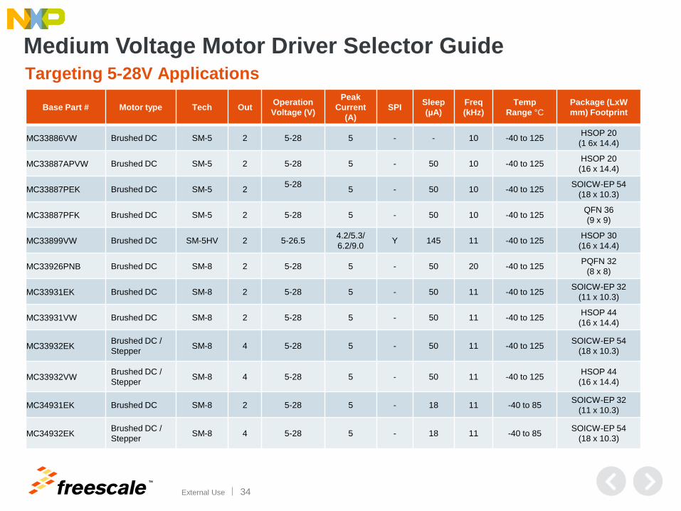
External Use 34
Base Part # Motor type Tech Out Operation
Voltage (V)
Peak
Current
(A)
SPI Sleep
(µA)
Freq
(kHz)
Temp
Range °C
Package (LxW
mm) Footprint
MC33886VW Brushed DC SM-5 2 5-28 5 - - 10 -40 to 125 HSOP 20
(1 6x 14.4)
MC33887APVW Brushed DC SM-5 2 5-28 5 - 50 10 -40 to 125 HSOP 20
(16 x 14.4)
MC33887PEK Brushed DC SM-5 2 5-28
5 - 50 10 -40 to 125
SOICW-EP 54
(18 x 10.3)
MC33887PFK Brushed DC SM-5 2 5-28 5 - 50 10 -40 to 125 QFN 36
(9 x 9)
MC33899VW Brushed DC SM-5HV 2 5-26.5 4.2/5.3/
6.2/9.0 Y 145 11 -40 to 125
HSOP 30
(16 x 14.4)
MC33926PNB Brushed DC SM-8 2 5-28 5 - 50 20 -40 to 125 PQFN 32
(8 x 8)
MC33931EK Brushed DC SM-8 2 5-28 5 - 50 11 -40 to 125 SOICW-EP 32
(11 x 10.3)
MC33931VW Brushed DC SM-8 2 5-28 5 - 50 11 -40 to 125 HSOP 44
(16 x 14.4)
MC33932EK Brushed DC /
Stepper SM-8 4 5-28 5 - 50 11 -40 to 125
SOICW-EP 54
(18 x 10.3)
MC33932VW Brushed DC /
Stepper SM-8 4 5-28 5 - 50 11 -40 to 125
HSOP 44
(16 x 14.4)
MC34931EK Brushed DC SM-8 2 5-28 5 - 18 11 -40 to 85 SOICW-EP 32
(11 x 10.3)
MC34932EK Brushed DC /
Stepper SM-8 4 5-28 5 - 18 11 -40 to 85
SOICW-EP 54
(18 x 10.3)
Medium Voltage Motor Driver Selector Guide Targeting 5-28V Applications

TM
External Use 35
H-Bridge DC Motor Drivers
Features Benefits
Automatic thermal back-off at high die temperatures Maintains operation at reduced current for continuous operation
Load current mirroring provides a proportional current
output (0.24% of the load current) Provides feedback to a microcontroller for control or protection
Robust thermally enhanced eSOIC or PQFN package Choice between smaller footprint or visual fillet inspection
MC33926 provides selectable slew rate control Allows tradeoff between higher efficiency or better EMC
Automatic maximum current regulation via pre-
determined MOSFET shut-off times Reduces safety and reliability risks
Integrated fault detection and interrupt flag for
under-voltage, over-current, and over-temperature Saves board space over discrete solution
Industrial parts with sleep mode < 12 μA current draw Reduced power consumption in standby mode
5.0V to 28V continuous operation, 40V transient Wide range of applications
MC33926R2 (PQFP)
MC33931EK & MC34931EK (SOIC) Single
MC33932EK & MC34932EK (SOIC) Dual

TM
External Use 36
• Integrated control, protection, fault detection, charge pump and MOSFETs in monolithic die
• Automatic fault flag interrupt for under-voltage, over-current, and over-temperature fault conditions
• Sleep mode automatic default with low current draw < 12 μA (each half with inputs floating or set to match default logic states on 34 series)
H-Bridge DC Motor Drivers
Product Differentiation
Thermal Efficiency Flexibility with Simplicity Integration
Easy system integration Best thermal performance in
proven robust process
• Thermally efficient package: 2X lower thermal impedance
• Automatic thermal back-off limits current at high temperatures to ensure continuous operation
• Low RDS(ON) for high efficiency operation
• Automotive grade SMARTMOS process for proven reliability with millions of application hours
• Current mirror for speed control, overload protection or diagnostics
• Large input voltage range for applications requiring 5 to 28 V
• Output short-circuit protection
• Over-current, over-voltage, over-temperature fault flag interrupt
• Selectable slew rate for improved EMC or increased efficiency on 926
Most thermally efficient 28V/5A H-bridge DC motor driver featuring real-time load current monitoring and automatic thermal current back-off for high availability operation in
demanding high current, high temperature automotive and industrial applications
Easy to use flexibility
MC33926R2 (PQFP)
MC33931EK & MC34931EK (SOIC) Single
MC33932EK & MC34932EK (SOIC) Dual

TM
External Use 37
MC33883 H-Bridge Gate Driver IC
Features
• -40ºC to 125ºC temperature range
• Vcc operating voltage range from
5.5V up to 55V
• Vcc2 operating voltage range from
5.5V up to 28V
• 1.0 A peak gate drive current
• Built-in high side charge pump
• CMOS/LSTTL compatible I/O
• Global enable with <10 µA sleep mode
• Supports PWM up to 100 kHz
Typical Applications
• Sine wave inverters
• Uninterruptable power supplies
• Motor control
-40 to 125ºC MC33883HEG
Product Options
Availability Samples: Now
Production: Now

TM
External Use 38
MC33926 Monolithic Single H-Bridge Motor Driver
32-Pin, PQFN
8x8 mm
Differentiating Points • Over temperature protection –
current fold back at 165ºC
• Current mirror – 1/400 out from current
flowing in MOSFET
• Selectable slew rate control
• Ultra-low thermal resistance < 1ºC/Watt, for superior
heat dissipation
• 235 mΩ maximum @ Tj=150°C , 120 mΩ typical
RDS(ON) @ Tj=25°C (for each H-bridge MOSFET)
• Over current limiting (regulation) via internal
constant-off-time PWM
• Output short circuit protection
(short to VPWR or ground)
• Temperature dependent current limit
threshold reduction
• 3 and 5V TTL/CMOS logic compatible inputs
Features • H-bridge configuration for bi-directional motors
• 5 to 28 Volt continuous; to 40 V transient operation
• 5 Amp peak output current
• Protected against common failure conditions

TM
External Use 39
MC33931/MC34931 Monolithic Single H-Bridge Motor Driver
Differentiating Points • Over temperature protection – current fold back at 165ºC
• Current mirror – 1/400 out from current flowing in
MOSFET
• Ultra-low thermal resistance < 1ºC/Watt for superior
heat dissipation
• Sleep mode current typical < 12 μA
• 235 mΩ maximum @ Tj=150°C , 120 mΩ typical
RDS(ON) @ Tj=25°C (for each H-bridge MOSFET)
• Over current limiting (regulation) via internal constant-off-
time PWM
• Output short circuit protection (short to VPWR or ground)
• Temperature dependent current limit threshold reduction
• 3 and 5V TTL/CMOS logic compatible inputs
Features • H-bridge configuration for bi-directional motors
• 5 to 28 Volt continuous; to 40 V transient operation
• 5 Amp peak output current
• Protected against common failure conditions
32-Pin, SOIC-EP
10x11 mm

TM
External Use 40
54-Pin, SOIC-EP
10x18 mm
MC33932/MC34932 Monolithic Dual H-Bridge Motor Driver
Differentiating Points
• Over temperature protection – current fold back at 165ºC
• Current mirror – 1/400 out from current flowing in MOSFET
• Ultra-low thermal resistance < 1ºC/Watt for superior heat
dissipation
• Sleep mode current typical < 12 μA
• 235 mΩ maximum @ Tj=150°C , 120 mΩ typical RDS(ON) @
Tj=25°C (for each H-bridge MOSFET)
• Over current limiting (regulation) via internal constant-off-time
PWM
• Output short circuit protection (short to VPWR or ground)
• Temperature dependent current limit threshold reduction
• 3 and 5V TTL/CMOS logic compatible inputs
Features
• H-bridge configuration for bi-directional motors
• 5 to 28 Volt continuous; to 40 V transient operation
• 5 Amp peak output current
• Protected against common failure conditions

TM
External Use 41
MC33899 Programmable Single H-Bridge Motor Driver
30-PIN SOIC-EP
14 x 16 mm
Differentiating Points • Designed to drive a DC motor in both forward and reverse
shaft rotation under PWM control of speed and torque
• SPI selectable current limit typical: 4.2 / 5.3 / 6.2 / 9.5 Amp
• SPI selectable slew rate
• SPI diagnostic reporting: open circuit, short-circuit to
PWR, short-circuit to GRN, die temperature range,
and under-voltage
• Current mirror output signal (gain selectable via external resistor)
• Short-circuit current limiting
• Over-temperature shutdown
Features • 5 to 28 Volt operation
• 5 Amp peak current
• Low RDS(ON) outputs at high junction temperature
(< 165mΩ @ TA = 125°C, VIGNP = 6.0V)
• Internal charge pump circuit for the internal
high side MOSFETs
• Outputs can be disabled to high-impedance state
• PWM-able up to 11 kHz @ 3.0A
• Outputs survive shorts to -1.0V

TM
External Use 42
Power Dissipation and
Thermal Analysis Tools
Power dissipation and thermal estimation with simulation
Power dissipation and thermal estimation with experimentation

TM
External Use 43
Factors Determining Power Dissipation
There are two cases: Steady state and dynamic.
Steady state (without switching)
• Type of load and current
• Change in RDS(ON)
• Body diode forward
voltage drop
Dynamic (with switching/PWM)
• Type of load and current
• Change in RDS(ON)
• Rise/fall time to the
system voltage
• Body diode forward
voltage drop

TM
External Use 44
RDS(ON) Vs Junction Temperature [°C]
0
20
40
60
80
100
120
140
160
180
200
-60 -40 -20 0 20 40 60 80 100 120 140
RD
S(O
N) [m
Ω]
Temperature [°C]

TM
External Use 45
Estimation of Power Dissipation Iload
PWM
Signal
Vout1
T1 T2 T3 T4
T
Switching Loss
PD_HS2 over T [W] = IOUT2*Rdson
PD_LS1 over T1 [W] = 0.5*(VPWR+VD- IOUT*Rdson)*IOUT*T1*FSW
PD_LS1 over T2 [W] = IOUT2*Rdson*T2*FSW
PD_LS1 over T3 [W] = 0.5*(VPWR+VD- IOUT*Rdson)*IOUT*T3*FSW
PD_HS1 over T4 [W] = IOUT2*Rdson*T4*FSW
Total Power Dissipation on the Die [W] = IOUT2*Rdson + 0.5*(VPWR+VD- IOUT*Rdson)*IOUT*T1*FSW+IOUT
2*Rdson*T2*FSW +0.5*(VPWR+VD- IOUT*Rdson)*IOUT*T3*FSW + IOUT
2*Rdson*T4*FSW

TM
External Use 46
Junction Temperature Estimation
Junction temperature (TJ) depends primarily on the following factors:
− Ambient temperature (TA)
− Thermal resistance from junction to ambient (RθJA) which depends on:
Number of layers in PCB
Amount of copper used on each layer
Thermal via size and number of vias
Type of solder used
Heat sink efficiency
Interface material
IC packaging
− Power dissipated on the die (PD)
Mathematically : TJ = TA + PD x RθJA

TM
External Use 47
Thermal Specifications for MC33931EK

TM
External Use 48
Transient Thermal Response (From Datasheet)

TM
External Use 49
Thermal Analysis Tools
• Tools to assist analyzing power dissipation
and thermal performance include:
• MC33887 Power Dissipation.xls
• MC33899 Power Dissipation.xls
• MC339xx H-Bridge Power Dissipation.xls
• MC339xx H-Bridge PWM Response.xls
• Available on the Freescale “Compass” site http://compass.freescale.net/livelink/livelink?func=ll&objId=208509673&objAction=browse&viewType=1

TM
External Use 50
Integration with FRDM Platform
Review and demonstration of evaluation boards

TM
External Use 51
Freescale FRDM-KL25Z
MKL25Z128VLK4
MCU Features • 48 MHz
• 128 KB flash
• 16 KB SRAM
• Capacitive touch “slider”
• MMA8451Q accelerometer
• Tri-color LED
• Easy access to MCU I/O
• Supports multiple IDE tools
• CodeWarrior
• IAR
• Keil
• Atollic
• Rowley
• Arrow Cloud Connect
• mbed

TM
External Use 52
FRDM Board FRDM Interface Connectors
Motor & Sensor Power Connector
Motor Connector
Sensor Connector
Motor Current
Sense Jumpers
Board ID Pins
Motor Control & Output Pins
- Test Pins
FRDM Board Connectivity with H-Bridge EVBs

TM
External Use 53
GUI Interface
GUI
Digital I/O
to
FRDM
(via USB)
EVB Ready OUT
IN
Board ID
Braking
CST / DYN Sens. Stop
ON / OFF
FWD / BCK
Speed #
EN/D2_b
Current FB
PWM and DC
Sample GUI
EVB Ready Fault Motor
Brushed Stepper
PWM Frequency
Duty Cycle
3.67 A
Current Display Ch1
EN/D2_b
Channel 1 Control
EN/D1
Fwd/Rev Coast/Dyn
Enabling/Disabling
Direction/Braking
5.0 A
Set max. current
PWM Frequency
Duty Cycle
2.5 A
Current Display Ch2
EN/D2_b EN/D1
Fwd/Rev Coast/Dyn
Enabling/Disabling
Direction/Braking
3.0 A
Set max. current
Channel 2 Control
Mode Auto Manual

TM
External Use 54
Enablements
Tools and Evaluation Boards

TM
External Use 55
KIT33887EKEVBE: Evaluation Kit – 33887
Evaluation Kit Includes The MC33887 monolithic power IC comprising control
logic, charge pump, gate drive, and low RDS(on)
MOSFET output H-bridge circuitry contained in a
small surface mount package.
Features
• Fully specified operation 5.0 V to 28 V
• Limited operation with reduced performance up to 40 V
• 120 mΩ RDS(ON) typical H-bridge MOSFETs
• TTL/CMOS compatible inputs
• PWM frequencies up to 10 kHz
• Active current limiting (regulation)
• Fault status reporting
• Sleep mode with current draw ≤50 μA (inputs floating or set to match default logic states)
• KIT33887EKEVBE

TM
External Use 56
KIT33926PNBEVBE: Evaluation Kit – 33926
The Evaluation Kit features the 33926, which is a monolithic H-Bridge Power IC designed primarily for automotive electronic throttle control, but is applicable to any low-voltage DC servo motor control application within the current and voltage limits stated.
Features • 8.0V to 28V continuous operation
(transient operation from 5.0 V to 40 V)
• 225 mΩ maximum RDS(ON) @ 150°C
(each H-bridge MOSFET)
• 3.0 V and 5.0 V TTL / CMOS
Logic compatible inputs
• Overcurrent limiting (regulation) via internal
constant-off-time PWM
• Output short circuit protection
(short to VPWR or ground)
• Temperature-dependant current-limit threshold
reduction
• All inputs have an internal source/sink to define the
default (floating input) states
• Sleep mode with current draw < 50 µA (with inputs
floating or set to match default logic states)
This Evaluation kit may be used with the
KITUSBSPIDGLEVME.
The MC33926 is a
SafeAssure functional safety solution
KIT33926PNBEVBE

TM
External Use 57
KIT33932VWEVBE: Evaluation Kit – 33932
The Evaluation Kit for the 33932 is a monolithic
H-bridge power IC in a robust thermally enhanced
package.
Features • 8.0 to 28V continuous operation
(transient operation from 5.0 to 40 V)
• 235 mΩ maximum RDS(ON) @ 150°C
(each H-bridge MOSFET)
• 3.0 V and 5.0 V TTL / CMOS
logic compatible inputs
• Over-current limiting (regulation) via internal
constant-off-time PWM
• Output short-circuit protection
(short to VPWR or GND)
• Temperature-dependent current-limit
threshold reduction
• All inputs have an internal source/sink to define
the default (floating input) states
• Sleep mode with current draw < 50 µA
(each H-bridge)
This Evaluation kit may be used with the
KITUSBSPIDGLEVME.
KIT33932VWEVBE

TM
External Use 58
KIT33932EKEVBE: Evaluation Kit – MC33932EK
The Evaluation Kit for the MC33932EK is a monolithic H-bridge power IC in a robust thermally enhanced package. The 33932 has two independent monolithic H-bridge power ICs in the same package.
Features • 8.0 to 28V continuous operation
(transient operation from 5.0 to 40 V)
• 235 mΩ maximum RDS(ON) @ 150 °C (each H-Bridge MOSFET)
• 3.0 V and 5.0 V TTL / CMOS logic compatible inputs
• Overcurrent limiting (regulation) via internal constant-off-time PWM
• Output short-circuit protection (short to VPWR or GND)
• Temperature-dependant current-limit threshold reduction
• All inputs have an internal source/sink to define the default (floating input) states
• Sleep mode with current draw < 50 μA (each H-bridge)
This Evaluation kit may be used with the
KITUSBSPIDGLEVME.
KIT33932EKEVBE
AN4833 - Parallel Configuration of H-Bridges

TM
© 2014 Freescale Semiconductor, Inc. | External Use
www.Freescale.com