Engineering Manual PCS 7 - industry.siemens.com · SIMATIC PCS7 V7.1 - GMP Engineering Manual...
136
GMP Engineering Manual Edition 06/2010 SIMATIC PCS 7 V7.1 Guidelines for Implementing Automation Projects in a GMP Environment p simatic p cs 7
Transcript of Engineering Manual PCS 7 - industry.siemens.com · SIMATIC PCS7 V7.1 - GMP Engineering Manual...
A5E02795571D-01 GN: 65000 - SIMATIC PCS 7 Pharma
GMP Engineering Manual Edition 06/2010
Siemens AG
Industry SectorIndustry Automation VMM Pharma76181 KARLSRUHEGERMANY
SIMATIC PCS 7 V7.1Guidelines for Implementing
Automation Projectsin a GMP Environment
[email protected]/simatic-pcs7
SIM
ATI
C P
CS
7 V
7.1
06
/20
10
GM
P En
gin
eeri
ng
Man
ual
psimatic pcs 7
A5E02795571-01
LANZENDO
low resolution
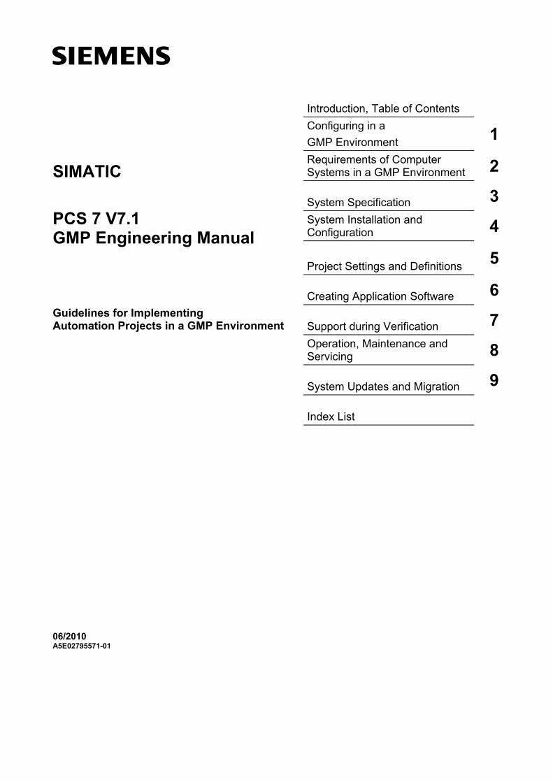
s Introduction, Table of Contents Configuring in a
GMP Environment 1
Requirements of Computer Systems in a GMP Environment 2 System Specification 3 System Installation and Configuration 4
Project Settings and Definitions 5
Creating Application Software 6 Support during Verification 7 Operation, Maintenance and Servicing 8 System Updates and Migration 9 Index List
SIMATIC
PCS 7 V7.1 GMP Engineering Manual
Guidelines for Implementing Automation Projects in a GMP Environment
06/2010 A5E02795571-01
Legal information Warning notice system
This manual contains notices you have to observe in order to ensure your personal safety, as well as to prevent damage to property. The notices referring to your personal safety are highlighted in the manual by a safety alert symbol, notices referring only to property damage have no safety alert symbol. These notices shown below are graded according to the degree of danger.
DANGER indicates that death or severe personal injury will result if proper precautions are not taken.
WARNING indicates that death or severe personal injury may result if proper precautions are not taken.
CAUTION with a safety alert symbol, indicates that minor personal injury can result if proper precautions are not taken.
CAUTION without a safety alert symbol, indicates that property damage can result if proper precautions are not taken.
NOTICE indicates that an unintended result or situation can occur if the corresponding information is not taken into account.
If more than one degree of danger is present, the warning notice representing the highest degree of danger will be used. A notice warning of injury to persons with a safety alert symbol may also include a warning relating to property damage.
Qualified Personnel The product/system described in this documentation may be operated only by personnel qualified for the specific task in accordance with the relevant documentation for the specific task, in particular its warning notices and safety instructions. Qualified personnel are those who, based on their training and experience, are capable of identifying risks and avoiding potential hazards when working with these products/systems.
Proper use of Siemens products Note the following:
WARNING Siemens products may only be used for the applications described in the catalog and in the relevant technical documentation. If products and components from other manufacturers are used, these must be recommended or approved by Siemens. Proper transport, storage, installation, assembly, commissioning, operation and maintenance are required to ensure that the products operate safely and without any problems. The permissible ambient conditions must be adhered to. The information in the relevant documentation must be observed.
Trademarks All names identified by ® are registered trademarks of the Siemens AG. The remaining trademarks in this publication may be trademarks whose use by third parties for their own purposes could violate the rights of the owner.
Disclaimer of Liability We have reviewed the contents of this publication to ensure consistency with the hardware and software described. Since variance cannot be precluded entirely, we cannot guarantee full consistency. However, the information in this publication is reviewed regularly and any necessary corrections are included in subsequent editions.
Siemens AG Industry Sector Industry Automation D-76181 KARLSRUHE GERMANY
A5E02795571-01 Ⓟ 06/2010
Copyright © Siemens AG 2010. Technical data subject to change
Introduction
SIMATIC PCS7 V7.1 - GMP Engineering Manual A5E02795571-01 3
Introduction
Purpose of this manual
This manual describes what is required, from the pharmaceutical, regulatory viewpoint in Good Manufacturing Practice (GMP environment), of the computer system, the software and the procedure for configuring such as system. The relationship between the requirements and implementation is explained with practical examples.
Target groups
This manual is intended for plant operators, those responsible for system designs for specific industries, project managers and programmers, servicing and mainte-nance personnel who use the automation and process control technology in the GMP environment.
Basic knowledge required
Basic knowledge about SIMATIC PCS 7 is required to understand this manual. Knowledge of GMP as practiced in the pharmaceutical industry is also an advan-tage.
Disclaimer of liability
This manual contains instructions for system users and project engineers for integrating SIMATIC PCS 7 process control systems into the GMP environment. It covers validation and takes into account special aspects such as the requirements of FDA 21 CFR Part 11 of the American Food and Drug Administration.
We have verified that the contents of this document correspond to the hardware and software described. However, since deviations cannot be precluded entirely, we cannot guarantee full consistency. The information in this document is checked regularly for system changes or changes to the regulations of the various organiza-tions and necessary corrections will be included in subsequent issues. We wel-come any suggestions for improvement and ask that they be sent to the I IA VMM Pharma in Karlsruhe (Germany).
Introduction
SIMATIC PCS7 V7.1 - GMP Engineering Manual 4 A5E02795571-01
Validity of the manual
The information in this manual applies to SIMATIC PCS 7 V7.1 including SP1. The components examined are the PCS 7-ES, PCS 7 OS, SIMATIC BATCH, as well as the Central Archive Server and StoragePlus add-ons. Refer to the CA01 catalog for detailed information on the compatibility of the individual components.
The catalog can be ordered over the Internet at www.siemens.com/automation/ca01.
A list relating to the compatibility of the various product versions is available at http://support.automation.siemens.com/DE/view/en/2334224.
Any questions about the compatibility of the add-on products for SIMATIC PCS 7 should be addressed directly to the suppliers, see http://www.automation.siemens.com/w2/automation-technology-simatic-pcs-7-add-ons-6811.htm.
Position in the information landscape
The system documentation of the SIMATIC PCS 7 V7.1 process control system is an integral part of the SIMATIC PCS 7 system software. It is available to every user as online help (HTML help) or as electronic documentation in PDF format.
This manual supplements the existing SIMATIC PCS 7 manuals. The guidelines are not only useful during configuration, they also provide an overview of the requirements for configuration and what is expected of computer systems in a GMP environment.
Structure of the manual
The regulations and guidelines, recommendations and mandatory specifications are explained. These provide the basis for configuration of computer systems.
All the necessary functions and requirements for hardware and software compo-nents are also described; this should make the selection of components easier.
Based on examples, the use of the hardware and software is explained briefly and how they are configured or programmed to meet the requirements. More detailed explanations can be found in the standard documentation.
Additional support
Contact your local Siemens representative and offices if you have any questions about the products described in this manual and do not find the right answers.
You will find your contact partner at:
http://www.siemens.com/automation/partner
A guide to the technical documentation of the various SIMATIC products and systems is available at:
http://www.siemens.com/simatic-tech-doku-portal
The online catalog and online ordering system are available at:
http://mall.automation.siemens.com/
Introduction
SIMATIC PCS7 V7.1 - GMP Engineering Manual A5E02795571-01 5
If you have questions on the manual, contact I IA VMM Pharma at:
E-mail: [email protected]
You can find additional information about the products, systems and services from Siemens for the pharmaceutical industry at:
http://www.siemens.com/pharma
Training center
We offer various courses for newcomers to SIMATIC PCS 7. Contact your regional Training Center or the central Training Center in D 90327 Nuremberg, Germany.
Internet: http://www.sitrain.com
Technical support
You can contact the Technical Support for all the I IA&DT products using the Web form for the support request
http://www.siemens.de/automation/support-request
Additional information about our technical support is available in the Internet at:
http://www.siemens.de/automation/service
Online service & support
In addition to our pool of documentation, we offer you a comprehensive online our knowledge base at:
http://www.siemens.com/automation/service&support
There you will find:
The newsletter that provides you with latest information relating to your product
The right documents for you, using our Service & Support search engine
A bulletin board in which users and specialists worldwide exchange their know-how
You local Siemens representative
Information about on-site services, repairs and spare parts. And much more under "Services".
Introduction
SIMATIC PCS7 V7.1 - GMP Engineering Manual 6 A5E02795571-01
Table of Contents
SIMATIC PCS7 V7.1 - GMP Engineering Manual A5E02795571-01 7
Table of Contents
Introduction.................................................................................................................................. 3
Table of Contents ........................................................................................................................ 7
1 Configuring in a GMP Environment................................................................................ 11 1.1 Regulations and Guidelines ....................................................................................... 11 1.2 Life Cycle Model......................................................................................................... 11 1.3 Responsibilities .......................................................................................................... 12 1.4 Approval and Change Procedure............................................................................... 13 1.5 Risk-Based Approach ................................................................................................ 13
2 Requirements of Computer Systems in a GMP Environment...................................... 14 2.1 Categorization of Hardware and Software................................................................. 14 2.2 Test Effort Depending on the Categorization............................................................. 14 2.3 Project Change and Configuration Management....................................................... 15 2.4 Software Creation ...................................................................................................... 15 2.5 Access Protection and User Management ................................................................ 16 2.5.1 Applying access protection to a system..................................................................... 16 2.5.2 Requirements of user IDs and passwords................................................................. 16 2.6 Requirements of Electronic Records ......................................................................... 17 2.7 Electronic Signatures ................................................................................................. 17 2.8 Audit Trail ................................................................................................................... 18 2.9 Reporting Batch Data................................................................................................. 18 2.10 Archiving Data............................................................................................................ 19 2.11 Data Backup............................................................................................................... 19 2.12 Retrieving Archived Data ........................................................................................... 19 2.13 Time Synchronization................................................................................................. 20 2.14 Use of Third-Party Components ................................................................................ 20
3 System Specification ....................................................................................................... 21 3.1 Specification of the System Hardware....................................................................... 21 3.1.1 Selecting the hardware components.......................................................................... 21 3.1.2 Hardware specification............................................................................................... 22 3.1.3 Hardware solutions for special automation tasks ...................................................... 23 3.2 System and Network Security.................................................................................... 23 3.3 Specification of the Basic Software............................................................................ 23 3.3.1 Operating system....................................................................................................... 24 3.3.2 Basic software for user administration....................................................................... 24 3.3.3 Engineering system software components ................................................................ 24 3.3.4 Operator control level software components ............................................................. 26
Table of Contents
SIMATIC PCS7 V7.1 - GMP Engineering Manual 8 A5E02795571-01
3.3.5 SIMATIC BATCH basics and options ........................................................................ 27 3.4 SIMATIC Additional Software .................................................................................... 28 3.4.1 SIMATIC PCS 7 add-ons ........................................................................................... 28 3.4.2 Long-term archiving with StoragePlus ....................................................................... 28 3.4.3 Long-term archiving with the Central Archive Server (CAS) ..................................... 28 3.5 Application Software Specifications ........................................................................... 28 3.6 Utilities and Drivers .................................................................................................... 29 3.6.1 Printer driver............................................................................................................... 29 3.6.2 Virus scanner ............................................................................................................. 29 3.6.3 Image & partition tools ............................................................................................... 30
4 System Installation and Configuration........................................................................... 31 4.1 Installation of the Operating System.......................................................................... 31 4.2 Installation of PCS 7................................................................................................... 31 4.3 Setting up User Administration .................................................................................. 31 4.3.1 User administration on the operating system level .................................................... 31 4.3.2 Security settings in Windows ..................................................................................... 33 4.3.3 SIMATIC user groups................................................................................................. 34 4.3.4 Configuring SIMATIC Logon ...................................................................................... 35 4.3.5 How access protection works .................................................................................... 35 4.4 Administration of User Rights .................................................................................... 36 4.4.1 Rights management on the ES.................................................................................. 36 4.4.2 Rights management on the OS.................................................................................. 39 4.4.3 Rights management in SIMATIC BATCH .................................................................. 41 4.5 Configuring Access Protection................................................................................... 42 4.5.1 Configuration settings in Windows............................................................................. 43 4.5.2 Configuration setting on SIMATIC PCS 7 OS............................................................ 43 4.5.3 Secure configuration .................................................................................................. 44 4.6 Information Security ................................................................................................... 44 4.6.1 SIMATIC Security Control (SSC) ............................................................................... 44 4.6.2 SCALANCE S ............................................................................................................ 44
5 Project Settings and Definitions ..................................................................................... 46 5.1 Multiproject Setup ...................................................................................................... 46 5.2 Referenced OS Stations ............................................................................................ 46 5.3 Using the Master Data Library ................................................................................... 47 5.3.1 Synchronizing shared declarations ............................................................................ 49 5.3.2 Synchronizing SFC types........................................................................................... 50 5.3.3 Synchronizing the plant hierarchy.............................................................................. 50 5.4 SIMATIC NET ............................................................................................................ 51 5.4.1 Configuring SIMATIC NET......................................................................................... 51 5.4.2 Plant bus and terminal bus ........................................................................................ 52 5.4.3 PROFIBUS................................................................................................................. 52 5.4.4 SIMATIC PDM............................................................................................................ 54 5.4.5 FOUNDATION Fieldbus (FF)..................................................................................... 55 5.5 OS Project Editor ....................................................................................................... 56 5.6 Time Synchronization................................................................................................. 57 5.7 Configuration Management........................................................................................ 59 5.8 Versioning Software Elements................................................................................... 60 5.8.1 Versioning AS elements in PCS 7 ............................................................................. 60
Table of Contents
SIMATIC PCS7 V7.1 - GMP Engineering Manual A5E02795571-01 9
5.8.2 Versioning OS elements in PCS 7 ............................................................................. 64 5.8.3 Additional information on versioning.......................................................................... 66
6 Creating Application Software ........................................................................................ 67 6.1 Software Modules, Types, and Typicals .................................................................... 67 6.1.1 Modules and typicals in PCS 7 .................................................................................. 67 6.1.2 Example of a process tag type................................................................................... 69 6.1.3 Automatic generation of block icons .......................................................................... 69 6.2 Bulk Engineering with the IEA.................................................................................... 71 6.3 Creating Process Diagrams ....................................................................................... 73 6.4 User-Specific Blocks and Scripts ............................................................................... 73 6.5 Interfaces to PCS 7.................................................................................................... 74 6.5.1 PCS 7 OS Web Option .............................................................................................. 74 6.5.2 Open PCS 7 ............................................................................................................... 75 6.5.3 SIMATIC BATCH API................................................................................................. 76 6.6 Recipe Control with SIMATIC Batch.......................................................................... 76 6.6.1 Batch definition of terms ............................................................................................ 76 6.6.2 Conformity with the ISA-88.01 standard .................................................................... 77 6.6.3 Important settings in SIMATIC BATCH...................................................................... 79 6.6.4 Creating batch reports ............................................................................................... 81 6.7 SIMATIC Route Control ............................................................................................. 82 6.8 Alarm Management.................................................................................................... 82 6.8.1 Specification............................................................................................................... 82 6.8.2 Message classes........................................................................................................ 83 6.8.3 Priorities ..................................................................................................................... 83 6.8.4 Suppressing, filtering, hiding...................................................................................... 84 6.8.5 Monitoring PCS 7 components .................................................................................. 85 6.8.6 Monitoring connected systems .................................................................................. 86 6.9 Audit Trail and Change Control.................................................................................. 86 6.9.1 PCS 7 ES ................................................................................................................... 87 6.9.2 PCS 7 OS................................................................................................................... 89 6.9.3 SIMATIC BATCH ....................................................................................................... 90 6.10 Configuration for Electronic Signatures ..................................................................... 92 6.10.1 Electronic signatures in SIMATIC BATCH................................................................. 92 6.10.2 Electronic signatures on PCS 7 OS........................................................................... 94 6.10.3 Electronic signatures on PCS 7 ES ........................................................................... 95 6.11 Data Backup............................................................................................................... 95 6.11.1 Backing up the system configuration ......................................................................... 95 6.11.2 Backing up the user software..................................................................................... 96 6.12 Recording and Archiving Data Electronically............................................................. 96 6.12.1 Determining the data to be archived.......................................................................... 96 6.12.2 Setting up process value archives ............................................................................. 97 6.12.3 Archiving batch data................................................................................................... 99 6.12.4 Long-term archiving with the Central Archive Server (CAS) ................................... 100 6.12.5 Long-term archiving with StoragePlus ..................................................................... 103 6.13 Uninterruptible Power Supply (UPS)........................................................................ 106 6.13.1 Configuration of a UPS ............................................................................................ 107 6.13.2 UPS configuration via digital inputs ......................................................................... 107 6.13.3 MASTERGUARD UPS systems .............................................................................. 108
7 Support during Verification ........................................................................................... 109 7.1 Test Planning ........................................................................................................... 109
Table of Contents
SIMATIC PCS7 V7.1 - GMP Engineering Manual 10 A5E02795571-01
7.2 Verification of Hardware........................................................................................... 110 7.3 Verification of Software ............................................................................................ 112 7.3.1 Software categorization according to GAMP Guide ................................................ 112 7.3.2 Verification of software products.............................................................................. 114 7.3.3 Verification of the application software .................................................................... 117 7.3.4 Simulation for test mode .......................................................................................... 118 7.4 Configuration Control ............................................................................................... 120 7.4.1 Versioning Projects with "Version Trail"................................................................... 120 7.4.2 Version comparison with Version Cross Manager (VXM)........................................ 122 7.4.3 Write protection for CFC/SFC charts and SFC types .............................................. 124
8 Operation, Maintenance and Servicing ........................................................................ 126 8.1 Operation and Monitoring ........................................................................................ 126 8.1.1 Process visualization................................................................................................ 126 8.1.2 Asset management .................................................................................................. 126 8.1.3 Regular Data Backups ............................................................................................. 127 8.2 Change Control during Operation ............................................................................ 128 8.3 Remote Maintenance............................................................................................... 128 8.4 System Recovery ..................................................................................................... 129
9 System Updates and Migration ..................................................................................... 131 9.1 Updates and Service Packs..................................................................................... 131 9.2 Migrating to PCS 7................................................................................................... 132
Index List.................................................................................................................................. 133
Configuring in a GMP Environment
SIMATIC PCS7 V7.1 - GMP Engineering Manual A5E02795571-01 11
1 Configuring in a GMP Environment
Before configuring computer systems in a GMP environment, approved specifica-tions must be available. Requirements contained in standards, recommendations, and guidelines must be observed when creating these specifications and when implementing and operating computer systems. This chapter deals with the most important sets of regulations and explains some of the basic ideas.
1.1 Regulations and Guidelines
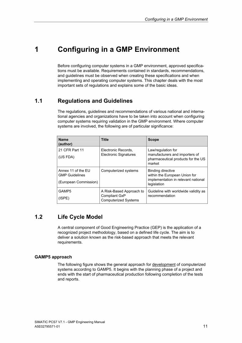
The regulations, guidelines and recommendations of various national and interna-tional agencies and organizations have to be taken into account when configuring computer systems requiring validation in the GMP environment. Where computer systems are involved, the following are of particular significance:
Name (author)
Title Scope
21 CFR Part 11
(US FDA)
Electronic Records, Electronic Signatures
Law/regulation for manufacturers and importers of pharmaceutical products for the US market
Annex 11 of the EU GMP Guidelines
(European Commission)
Computerized systems Binding directive within the European Union for implementation in relevant national legislation
GAMP5
(ISPE)
A Risk-Based Approach to Compliant GxP Computerized Systems
Guideline with worldwide validity as recommendation
1.2 Life Cycle Model
A central component of Good Engineering Practice (GEP) is the application of a recognized project methodology, based on a defined life cycle. The aim is to deliver a solution known as the risk-based approach that meets the relevant requirements.
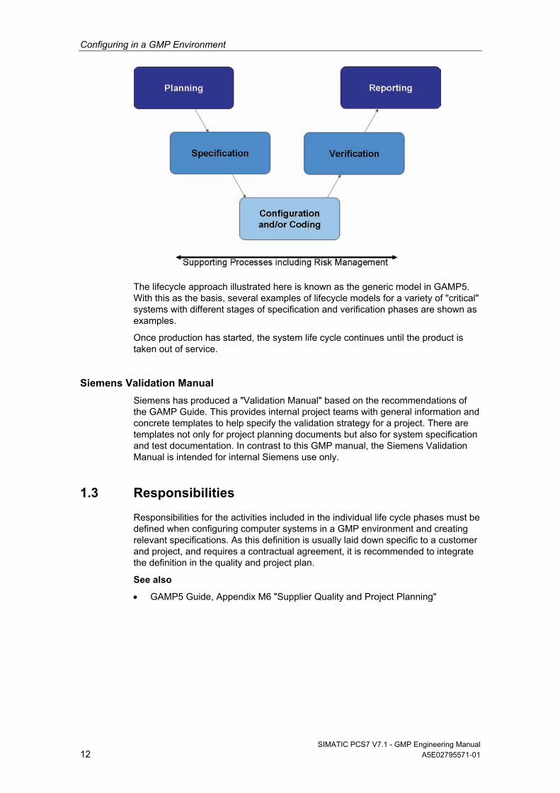
GAMP5 approach
The following figure shows the general approach for development of computerized systems according to GAMP5. It begins with the planning phase of a project and ends with the start of pharmaceutical production following completion of the tests and reports.
Configuring in a GMP Environment
SIMATIC PCS7 V7.1 - GMP Engineering Manual 12 A5E02795571-01
The lifecycle approach illustrated here is known as the generic model in GAMP5. With this as the basis, several examples of lifecycle models for a variety of "critical" systems with different stages of specification and verification phases are shown as examples.
Once production has started, the system life cycle continues until the product is taken out of service.
Siemens Validation Manual
Siemens has produced a "Validation Manual" based on the recommendations of the GAMP Guide. This provides internal project teams with general information and concrete templates to help specify the validation strategy for a project. There are templates not only for project planning documents but also for system specification and test documentation. In contrast to this GMP manual, the Siemens Validation Manual is intended for internal Siemens use only.
1.3 Responsibilities
Responsibilities for the activities included in the individual life cycle phases must be defined when configuring computer systems in a GMP environment and creating relevant specifications. As this definition is usually laid down specific to a customer and project, and requires a contractual agreement, it is recommended to integrate the definition in the quality and project plan.
See also
GAMP5 Guide, Appendix M6 "Supplier Quality and Project Planning"
Configuring in a GMP Environment
SIMATIC PCS7 V7.1 - GMP Engineering Manual A5E02795571-01 13
1.4 Approval and Change Procedure
When new systems requiring validation are set up or when existing systems requiring validation are changed, the top priority is to achieve or retain validated status, which means ensuring the traceability of the steps undertaken.
Before setting up or modifying a system, it is therefore necessary to plan and document the pending steps in terms functionality and time, and to obtain approval by the customer respectively by the plant operating company.
1.5 Risk-Based Approach
Both the US agency FDA ("cGMPs 21st Century", 2004) and the industry associa-tion ISPE/GAMP ("GAMP5" guidelines, 2008) recommend a risk-based approach to the validation of systems. This means that whether and to what extent a system should be validated depends on its complexity and its influence on the product quality.
Requirements of Computer Systems in a GMP Environment
SIMATIC PCS7 V7.1 - GMP Engineering Manual 14 A5E02795571-01
2 Requirements of Computer Systems in a GMP Environment
This chapter describes the essential requirements an automated system must meet in the GMP environment in terms of using computer systems. These require-ments must be defined in the specification and implemented during configuration. When subsequent modifications or interventions are made in the system, evidence must be provided at all times as to who has performed the change, what the change involved and the time the change took place (the "why" is optional). The requirements of this task are implemented in various functions and described in the following chapters.
Note
This chapter provides the general requirements for computer systems. How to meet these requirements with a specific system is dealt with starting at chapter 3.
2.1 Categorization of Hardware and Software
Hardware categorization
According to the GAMP Guide, hardware components of a system fall into two categories "standard hardware components" (category 1) and "custom built hardware components" (category 2).
Software categorization
According to the GAMP Guide, the software components of a system are divided into various software categories. These include commercially available and preconfigured "standard" software products that are simply installed, configured software products, right through to custom applications ("programmed software").
2.2 Test Effort Depending on the Categorization
The effort involved in validation (specification and testing) is much greater when using configured and, in particular, customized products compared to the effort for standard products (hardware and/or software). The overall effort for validation can therefore be significantly reduced by extensive use of standard products.
Requirements of Computer Systems in a GMP Environment
SIMATIC PCS7 V7.1 - GMP Engineering Manual A5E02795571-01 15
2.3 Project Change and Configuration Management
All the controlled elements of a system should be identified by name and version and any changes made to them should be checked. The transition to the opera-tional procedure should be decided in good time.
The procedure includes, for example:
Identification of the elements affected
Identification of the elements by name and version number
Change control
Control of the configuration (storage, release, etc.)
Periodic checks of the configuration
See also
GAMP5 Guide, Appendix M8 "Project Change and Configuration Management"
2.4 Software Creation
Certain guidelines must be followed during software creation and documented in the quality and project plan (GEP idea). Guidelines for software creation can be found in the GAMP Guide and other relevant standards and recommendations.
Using typicals for programming
While the validation of standard software only calls for the software name and version to be checked, customized software validation requires the entire range of functions to be checked and a supplier audit to be performed.
To keep the required level of validation work as low as possible, priority must be given to standardized function blocks (products, in-house standards, project standards) during configuration. Standard function blocks are used to create and test customized typicals in accordance with design specifications.
Identifying software modules/typicals
When software is created, the individual software modules must be assigned a unique name, a version, and a short description of the module.
Changing software modules/typicals
Changes to software modules should be appropriately documented. Apart from incrementing the version identifier, the date and the name of the person performing the change should be recorded, when applicable with a reference to the corre-sponding change request/order.
Requirements of Computer Systems in a GMP Environment
SIMATIC PCS7 V7.1 - GMP Engineering Manual 16 A5E02795571-01
2.5 Access Protection and User Management
To ensure that computer systems in a GMP environment are secure, such systems must be equipped with an access-control system. In addition to physical access control, access-control systems protect systems against unauthorized logical access. Users are assembled into groups, which are then used to manage user rights. Individual users can be granted access authorization in various ways:
A combination of unique user ID and password - a description of the configura-tion can be found in chapter 2.5.2 "Requirements of user IDs and passwords".
Smart cards together with a password
Evaluation of biometrics
2.5.1 Applying access protection to a system
In general, actions that can be executed on a computer system should be pro-tected against unauthorized access. Depending on a user's particular field of activity, a user can be assigned various rights. Access to user administration should only be given to the system owner or to a very limited number of employ-ees. Unauthorized access to electronically recorded data must also be prevented.
The use of an automatic logout function is advisable and provides additional access protection. This does not, however, absolve the user from the general responsibility of logging off when leaving the system. The automatic logout time should be agreed with the user and defined in the specification.
Note
Only authorized persons must be able to access PCs and the system. This can be ensured by using appropriate measures such as mechanical locks and hardware and software for remote access.
2.5.2 Requirements of user IDs and passwords
User ID:
The user ID for a system must be of a minimum length defined by the customer and be unique within the system.
Password:
When defining passwords, the minimum number of characters and the expiry period for the password should be defined. A password should generally comprise a combination of characters with a minimum length and should also meet at least three of the criteria listed below.
Use of uppercase letters
Use of lowercase letters
Use of numerals (0-9)
Use of special characters
The configuration is described in chapter 4.3, "Setting up User ".
Requirements of Computer Systems in a GMP Environment
SIMATIC PCS7 V7.1 - GMP Engineering Manual A5E02795571-01 17
2.6 Requirements of Electronic Records
When using electronic records for relevant data, the following requirements apply:
The system must be validated.
Only authorized persons must be able to enter or change data (access protection).
Changes to data or deletions must be recorded (audit trail).
Relevant electronic records for long-term storage must be archived securely and kept available for their retention period.
The initials and signatures required by the regulations must be implemented as electronic signatures.
"Relevant" production steps / processes, "significant" interim stages and "major" equipment must be defined in advance by the person responsible from a pharmaceutical perspective; this definition is often process-specific.
If an electronic manufacturing log is used, its structure and contents must match the structure and contents of the manufacturing formula / processing instructions. As an alternative, the manufacturing instructions and log can also be combined in one document.
See also
EU GMP Guidelines, chapter4.9
21 CFR Part 11 “Electronic Records, Electronic Signatures”
2.7 Electronic Signatures
An electronic signature is computer-generated information that acts as the legally binding equivalent of a handwritten signature.
Regulations concerning the use of electronic signatures are defined, for example, in US FDA 21 CFR Part 11.
Electronic signatures are of practical relevance, for example, when entering data and intervening manually during runtime, approving process actions and data reports, and changing recipes.
Each electronic signature must be uniquely assigned to one person and must not be used by any other person.
Note
The FDA regulations including 21 CFR Part 11 relating to electronic signatures must be satisfied in the manufacture of all pharmaceutical products and medical devices, that are intended for the US market.
Conventional electronic signatures
If electronic signatures are used that are not based on biometrics, they must be created so that persons executing signatures must identify themselves using at least two identifying components. This also applies in all cases where a smart card replaces one of the two identification components. These identification components can, for example, be a user ID and a password.
Requirements of Computer Systems in a GMP Environment
SIMATIC PCS7 V7.1 - GMP Engineering Manual 18 A5E02795571-01
The identification components must be assigned uniquely and must only be used by the actual owner of the signature.
Electronic signatures based on biometrics
An electronic signature based on biometrics must be created in such a way that it can only be used by one person. If the person making the signature does so using biometric methods, one identification component is adequate.
Biometric characteristics include fingerprints, iris structure, etc.
2.8 Audit Trail
The audit trail is a control mechanism of the system that allows the tracking of all data entered or modified. A secure audit trail is particularly important when GMP-relevant electronic records are created, modified or deleted.
Such an audit trail must document all the changes or actions made along with the date and time. The typical content of an audit trail describes who changed what and when (old value / new value), as an option it may also include "why".
2.9 Reporting Batch Data
When producing pharmaceuticals and medical devices, batch documentation takes on a special significance. For a pharmaceutical manufacturer, methodically created batch documentation is often the only documented evidence within the framework of product liability.
The components of batch documentation are as follows:
Manufacturing formula / processing instructions and manufacturing log
Packaging instructions and packaging log (from a pharmaceutical point of view, the packaging of the finished medicinal product is part of the manufacturing process)
Test instructions and test log (relating to quality checks, for example analysis)
The manufacturing log (or packaging log) has a central significance here and this is defined below:
The manufacturing log is always both product-related and batch-related.
It is always based on the relevant parts of the valid manufacturing formula and processing instructions.
It records all measurement and control procedures relevant to the process as actual values
It compares these with the specified target values
Requirements of Computer Systems in a GMP Environment
SIMATIC PCS7 V7.1 - GMP Engineering Manual A5E02795571-01 19
2.10 Archiving Data
Electronic archiving refers to the permanent safekeeping of electronic data and records in long-term storage.1
The customer is responsible for defining procedures and controls relating to the safekeeping of electronic data.
Based on predicate rules (EU GMP Guidelines, 21 CFR Part 210/211, etc.), the customer must decide how electronic data will be retained and, in particular, which data will be involved by this procedure. This decision must be founded on a sound and documented risk assessment, which also takes the relevance of the electronic data over the retention period into account.
If archived data is migrated or converted, the integrity of that data must be safe-guarded throughout the entire conversion process..2
2.11 Data Backup
In contrast to the archiving of electronic data, data backups are used to create backup copies that allow the system to be restored in case of original data loss or system breakdown.1
The backup procedure must include the periodic backup of volatile information to avoid total loss of data due to defective system components or inadvertent deletion of data. Backup procedures must be tested to ensure that data is saved correctly. Backup records should be labeled clearly and intelligibly, and dated.3 Backups are created on external media. The data media used should comply with the recommendations of the device manufacturer.
When backing up electronic data, the following distinctions are made
Backup of the installation, for example partition image
Backup of the application
Backup of archive data, for example process data
Here, particular attention is paid to the storage of data backup media (storage of the copy and original in different locations, protection from magnetic fields, and natural hazards).
2.12 Retrieving Archived Data
Archived/backed up data must be retrievable at all times. If the system is updated, care must be taken that the data transferred to archive prior to the update remains compatible.
1 "Good Practice and Compliance for Electronic Records and Signatures. Part 1, Good Electronic Records Management". ISPE/PDA 2001 2 "Good Practice and Compliance for Electronic Records and Signatures. Part 3, Models for Systems Implementation and Evolution". PDA 2004 3 "Electronic Records and Electronic Signatures Assessment", Chris Ride & Barbara Mullendore. PDA 2001
Requirements of Computer Systems in a GMP Environment
SIMATIC PCS7 V7.1 - GMP Engineering Manual 20 A5E02795571-01
2.13 Time Synchronization
A uniform time reference (including a time zone reference) must be guaranteed within a system, to be able to assign an unequivocal time stamp for archiving messages, alarms etc.
Time synchronization is especially important for archiving data and analysis of faults. UTC (Universal Time Coordinated, defined in ISO 8601) is recommended as the time base for saving data. The time can be displayed in local time with a note regarding daylight saving time and standard time.
2.14 Use of Third-Party Components
When third-party components (hardware and software) are used, their compatibility to other components in use must be confirmed. If components specifically "tailored" (customized) to individual projects are used, a supplier audit should be considered in order to check the supplier and their quality management system.
See also
GAMP5 Guide, Appendix M2 "Supplier Assessment"
System Specification
SIMATIC PCS7 V7.1 - GMP Engineering Manual A5E02795571-01 21
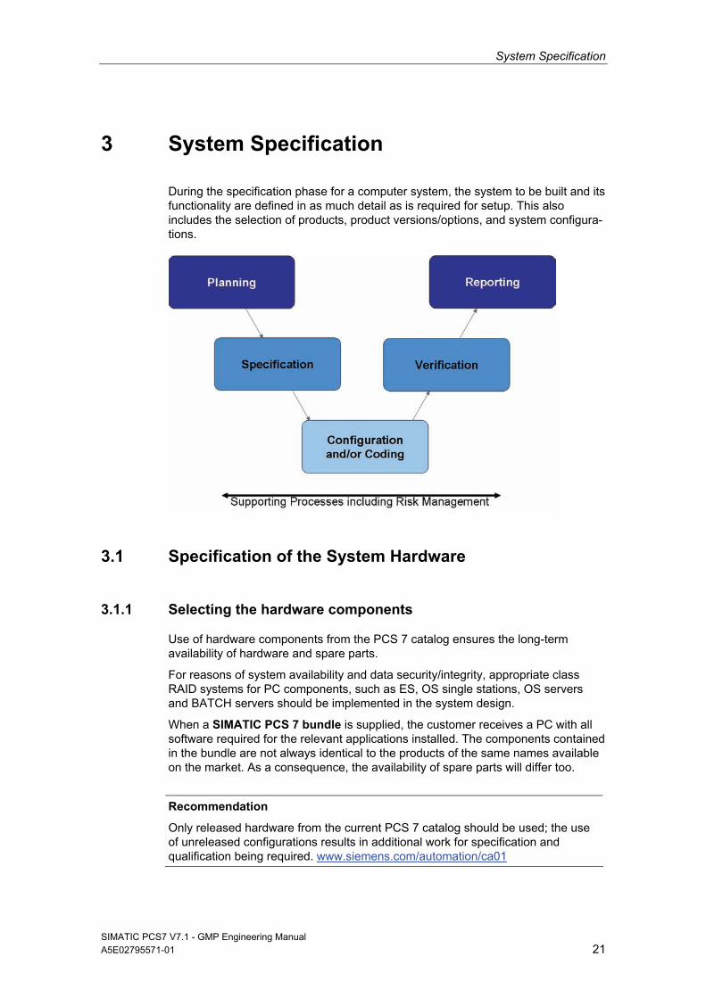
3 System Specification
During the specification phase for a computer system, the system to be built and its functionality are defined in as much detail as is required for setup. This also includes the selection of products, product versions/options, and system configura-tions.
3.1 Specification of the System Hardware
3.1.1 Selecting the hardware components
Use of hardware components from the PCS 7 catalog ensures the long-term availability of hardware and spare parts.
For reasons of system availability and data security/integrity, appropriate class RAID systems for PC components, such as ES, OS single stations, OS servers and BATCH servers should be implemented in the system design.
When a SIMATIC PCS 7 bundle is supplied, the customer receives a PC with all software required for the relevant applications installed. The components contained in the bundle are not always identical to the products of the same names available on the market. As a consequence, the availability of spare parts will differ too.
Recommendation
Only released hardware from the current PCS 7 catalog should be used; the use of unreleased configurations results in additional work for specification and qualification being required. www.siemens.com/automation/ca01
System Specification
SIMATIC PCS7 V7.1 - GMP Engineering Manual 22 A5E02795571-01
Note
If PCs are placed in control cabinets, make sure that provision is made for the use of suitable hardware components, such as operator channel extensions.
There are different types of automation systems.
Standard automation system
Fault-tolerant automation system The user programs loaded in both CPUs are fully identical and are run syn-chronously by both CPUs. The failover has no effect on the ongoing process because it is bumpless.
Fail-safe automation system Such systems automatically bring the plant to a safe state in the event of a fault. The relevant national regulations must be observed when configuring, commissioning, and operating fail-safe systems. S7 F-systems provide a refer-ence sum of the fail-safe program section available. This sum is recorded to enable the detection of changes in the fail-safe program.
See also
Manual "PCS 7 PC Configuration and Authorization"
3.1.2 Hardware specification
The Hardware Design Specification (acronym: HDS) describes the hardware architecture and configuration. The HDS should, for example define the points listed below. This specification is used later as a test basis for the IQ and OQ.
Hardware overview diagram
Network structure
PC components for server and client
Automation system with CPUs, I/O cards, etc.
Field devices
The HDS can be formulated as part of the Functional Specification or in a separate document.
Note
The information in the hardware overview diagram and the naming of hardware components must be unequivocal.
See also
GAMP5 Guide, Appendix D3 "Configuration and Design"
System Specification
SIMATIC PCS7 V7.1 - GMP Engineering Manual A5E02795571-01 23
3.1.3 Hardware solutions for special automation tasks
Additional device-specific solutions are required to integrate hardware components which are not offered in the SIMATIC hardware manager. These components are interfaced using special device master data (GSD). Integration examples for such hardware components include:
Integration of weighing modules (SIWAREX)
Integration of frequency inverters for drives (Masterdrives, Micromaster, etc.)
Integration of user-specific field devices
To keep validation work to a minimum, hardware components from the PCS 7 add-on catalog (ST PCS 7.A) should be given preference.
3.2 System and Network Security
In the field of modern process control systems, the boundaries between the office and automation environments are disappearing at an ever increasing rate.
Automation solutions linked to WEB clients, MES applications, and customer-specific office networks and applications are gaining in importance. To satisfy these demands and ensure as high a level of data security as possible, the planning and structure of networked PCS 7 automation solutions are highly important.
See also
Manual "Security Concept PCS 7 and WinCC"
Opportunities for improving plant security
PCS 7 offers several ways to improve information security within a plant. These include:
Staggered user, group, and role concept
SIMATIC Security Control (SSC)
SCALANCE S firewall and VPN modules
For more information, see chapter 4.6 "Information Security".
3.3 Specification of the Basic Software
The Software Design Specification (acronym: SDS) describes the software’s architecture and configuration. It includes a description of the application software, as well as a definition of the standard software components used in the system, which are specified by means of their name, version number, etc. This description serves as a reference when performing subsequent tests (FAT, SAT, IQ, OQ).
Commercially available standard software components include automation soft-ware components and software provided by third parties, see also chapter 7.3 "Verification of Software".
System Specification
SIMATIC PCS7 V7.1 - GMP Engineering Manual 24 A5E02795571-01
3.3.1 Operating system
Information regarding the operating system installation can be found in the latest "PCS 7 – PC Configuration and Authorization" manual. Information on hardware and software requirements is also provided in the readme file on the PCS 7 Toolset DVD.
3.3.2 Basic software for user administration
Access to the SIMATIC PCS 7 system components is controlled via SIMATIC Logon. More information on the installation and configuration of the various SIMATIC Logon components can be found in chapter 4.3 "Setting up User " and in the configuration manual for SIMATIC Logon.
3.3.3 Engineering system software components
Some of the most important functions of the SIMATIC PCS 7 engineering software are described below.
Multiproject engineering
See chapter 5.1 "Multiproject Setup" for information on how multiprojects are set up and used.
Process control libraries
The process control libraries contain ready-made, tested objects (blocks, face-plates, and symbols). When these libraries are used, engineering is usually limited to the configuration of the relevant objects. One major advantage of using prede-fined objects when project engineering automated systems in the pharmaceutical industry is the lower-level software categorization (see chapter 7.3.1 "Verification of Software") and the possibility of implementing updates. Therefore, the validation work required is less than that for user-specific blocks.
CFC (Continuous Function Chart)
The CFC editor provides a graphic interface for configuring automation and control functions. Drag & drop is used to move function blocks from libraries to a CFC chart, where they are interconnected and configured in accordance with require-ments.
SFC (Sequential Function Chart)
The SFC Editor facilitates the graphic configuration and commissioning of sequen-tial controls. The most important components are steps and transitions, as well as simultaneous and alternative branches.
System Specification
SIMATIC PCS7 V7.1 - GMP Engineering Manual A5E02795571-01 25
Import/Export Assistant
The Import/Export Assistant is a tool used to configure systems which feature recurring functions and/or plant units. Process tag lists or CAD charts previously created in the planning phase are used during configuration to create CFC charts for process tags, for the most part automatically. During this process, replicas of the modules are generated and then supplied with specific data.
For more information on the configuration and use of the IEA, see chapter 6.2 "Bulk Engineering with the IEA".
Version Trail
SIMATIC PCS 7 Version Trail enables multiprojects, single projects, and project-specific libraries to be backed up together with the assignment of unique version ID for the archived projects.
For more information on the configuration and use of "Version Trail", see chapter 7.4.1 "Versioning Projects with "Version Trail"".
Version Cross Manager
The Version Cross Manager is an add-on package for PCS 7, which allows two PCS 7 user projects or libraries to be compared and any differences to be dis-played. Multiprojects cannot be compared.
For more information on the configuration and use of the VXM, see chapter 7.4.2 "Version comparison with Version Cross Manager (VXM)".
Route Control
The SIMATIC Route Control add-on package is used to configure, monitor, and diagnose materials handling (paths) within a plant. It is fully integrated in SIMATIC PCS 7 and SIMATIC BATCH.
For more information on the configuration and use of "SIMATIC Route Control", (see chapter 6.7 "SIMATIC Route Control".
Simulation with S7-PLCSIM
S7 PLCSIM is a simulation tool for S7 user programs. This software component, which is available as an option, simulates a SIMATIC S7-CPU on a programming device or PC. The configured application software can be tested without the use of AS hardware (CPU and/or signal modules). Only one CPU can be simulated at a given time. Communications processors and Route Control cannot be simulated.
Note
The use of S7 PLCSIM is of particular interest for the test system, e. g. for typical tests. For a subsequent operation with an Ethernet network, the Ethernet connection should already be chosen in PLCSIM, since in the case of MPI all communication links would have to be reconfigured.
System Specification
SIMATIC PCS7 V7.1 - GMP Engineering Manual 26 A5E02795571-01
3.3.4 Operator control level software components
Basic software for operator system (OS)
Systems for the operator control and monitoring of the plant are implemented either as single or multiple station systems.
With a single station system, all operator control and monitoring tasks can be handled on one PC.
A multiple station system (client/server architecture) consists of operator stations (OS clients) and one or more OS servers, which supply the OS clients with data.
Redundant systems can be set up to increase availability.
Note
The number of licenses for the operator stations can be increased at a later time using suitable power packs. When extending/updating a license, the existing license must be available, i.e. runtime cannot be active. Online extension is only possible for redundant servers.
OS archiving
Process values and messages are stored in a short-term archive based on Microsoft SQL server technology. The data saved in the short-term archive can be moved to long-term archives, see chapter 6.12.2 "Setting up process value archives".
SFC Visualization add-on software
An SFC (sequential function chart) is used for the sequential control (also known as a sequencer) of processes. SFCs consist of a sequence of steps that are separated from one another in each case by step enabling conditions (or transi-tions). Using SFC Visualization, the configured SFCs can be displayed on the operator station and operated in manual mode. Processes can be clearly displayed by showing their different process actions.
No additional effort is necessary to configure the SFC visualization.
Open PCS 7 add-on software
Open PCS 7 can be used to exchange data with external systems, such as the plant management and production control level, MES level, or ERP level via the OPC interface, without knowledge of the PCS 7 project topology being required. OPC (OLE for Process Control) refers to a uniform, vendor-independent software interface, the standard of which was defined by the OPC Foundation. The OPC Foundation is an alliance of leading companies in the field of industrial automation. Information on OPC can be found on the Internet at http://www.opcfoundation.org; the use of "Open PCS 7" is described in more detail in chapter 6.5.2 "Open PCS 7".
System Specification
SIMATIC PCS7 V7.1 - GMP Engineering Manual A5E02795571-01 27
OS Web Client add-on software
The PCS7 OS Web option enables the PCS 7 plant to be operator controlled and monitored via the Intranet or Internet.
Note
Use of the Web option in a controlled environment must be thoroughly discussed with the customer. Issues such as access to the web client, critical or non-critical operator control and monitoring functions, Logon, and audit trail, as well as a secure data connection, must be considered during these discussions.
For more information on the use and configuration of the Web option, refer to chapter 6.5.1 "PCS 7 OS Web Option", and to the manual "PCS 7 OS Web Option".
3.3.5 SIMATIC BATCH basics and options
The SIMATIC BATCH software is integrated in SIMATIC PCS 7. It can be operated as a single user station system or a client/server system and can be used in various different plants, thanks to its modular architecture and scalability. SIMATIC BATCH servers can be configured redundantly.
Basic SIMATIC BATCH components include the "Batch Control Center" (BatchCC), used for the operator control and monitoring of the recipe control strategy, and the Recipe Editor (recipe system), used for creating and managing master recipes and library operations.
Several useful add-on packages are available in addition to the basic configuration:
ROP Library Managing recipe operations from a central location ensures that changes can be made centrally and that any such changes are passed on to all instances. The reference to the master module can be resolved later in the project.
Hierarchical Recipe Recipe procedures, recipe unit procedures, and recipe operations to perform the process engineering task can be clearly structured.
Separation of Procedures and Formulas Separating the procedure and the parameter sets further increases flexibility by means of recipes which are not specific to a particular unit.
SIMATIC BATCH API The SIMATIC BATCH application programming interface (API) is an open in-terface, which enables the user to access SIMATIC BATCH data and functions via the plant control level, for example.
Batch Planning Batch planning and control are supported in a user-friendly manner and simpli-fied, thanks to special displays such as the order category list, production order list, batch planning list, batch status list, or batch results list.
Refer to the system documentation for more information on using and configuring the add-on packages.
System Specification
SIMATIC PCS7 V7.1 - GMP Engineering Manual 28 A5E02795571-01
3.4 SIMATIC Additional Software
3.4.1 SIMATIC PCS 7 add-ons
The SIMATIC PCS 7 Add-On catalog contains solutions for various areas of application or special branches, such as the process industries. The addresses of the relevant contacts for these add-ons are listed in the catalog.
Recommendation
When implementing functions that go beyond the standard scope of PCS 7, priority should be given to add-ons from the current catalogues. https://pcs.khe.siemens.com/index_pcs_7_add_ons-6811.htm
3.4.2 Long-term archiving with StoragePlus
StoragePlus (see also chapter 6.12.5 "Long-term archiving with ") is used for the long-term archiving of process values, messages, batch data, and reports from up to four servers. The archives managed using StoragePlus can be cataloged and transferred to external media. Process values can be read at a maximum rate of 1,000 per second per server. If data is read from more than one server at once, the maximum rate is 1,600 per second.
3.4.3 Long-term archiving with the Central Archive Server (CAS)
The central archive server (CAS) is used for the long-term archiving of process values, messages, batch data, and reports from up to 11 servers; see also chapter 6.12.3 "Archiving batch data". The archives managed using the CAS (process values, messages, batch data) can be cataloged and transferred to external media. Process values can be read at a maximum rate of 1,000 per second per server. If data is read from more than one server at once, the maximum rate is 10.000 per second.
The CAS server can also have a redundant design if required.
3.5 Application Software Specifications
In addition to defining the standard software components used, another essential task of the Software Design Specification (SDS) is to specify the application software. This is then used as a basis for subsequent testing of the application software (FAT, SAT, IQ, OQ).
The SDS can be integrated in other specification documents (FS, DS). However, part of this specification usually is covered in other, separate documents, such as a process tag list, I/O list, parameter list, P&I, etc. The status of these documents (version, release) must be uniquely defined, as it must for other specification documents (URS, FS, DS).
System Specification
SIMATIC PCS7 V7.1 - GMP Engineering Manual A5E02795571-01 29
The SDS includes the following, for example:
Plant hierarchy
Software structure
Archiving, messages, trends, etc.
Module specification, possibly in a separate document,
provided that these have not already been adequately defined in the FS.
See also
GAMP5 Guide, Appendix D3 "Configuration and Design"
Note
As a basis for configuring batch control, SIMATIC PCS 7 uses the model of ANSI/ISA-88.01, see also chapter 6.6.2 “Conformity with the ISA-88.01 standard“.
3.6 Utilities and Drivers
3.6.1 Printer driver
It is advisable to use the printer drivers integrated in the operating system and approved for PCS 7. If external drivers are used, no guarantee of proper system operation can be provided.
3.6.2 Virus scanner
The use of virus scanners in process mode (runtime) is permitted. You can find additional information regarding the selection and configuration of virus scanners as well as their updating in the PCS 7 readme files, in the product support http://support.automation.siemens.com/DE/view/de/2334224 and in the manual "PCS 7 Setting up antivirus software".
When virus scanners are used, the following settings must be observed:
The real-time search is one of the most important functions. It is sufficient, however, to restrict the analysis to incoming data traffic.
The time-controlled search should be deactivated, as it significantly limits system performance in process mode.
The manual search should not be executed during process mode. It can be run at regular intervals, e.g. during maintenance cycles.
These specifications must be laid down in an SOP.
System Specification
SIMATIC PCS7 V7.1 - GMP Engineering Manual 30 A5E02795571-01
3.6.3 Image & partition tools
Add-on software for a disk "image" and "partition" enables you to backup the entire contents of hard disks by making an image of the disk, as well as to partition disks. Backing up system and application software by means of such an image can be used to quickly restore a system. Backed up hard drive contents can also be exported to devices with identical construction. This simplifies the replacement of computers.
Siemens provides the software package "SIMATIC Image and Partition Creator (IPC)" to perform these tasks. This can even be done without separate installation by starting the program directly from CD or USB Flash Drive.
Note
The created images are used to restore the installed system, but not to back up online data.
Administration skills are required for the selection and configuration of this software component.
System Installation and Configuration
SIMATIC PCS7 V7.1 - GMP Engineering Manual A5E02795571-01 31
4 System Installation and Configuration
4.1 Installation of the Operating System
When selecting the operating system, observe the information given in chapter 3 and the sources named therein.
See also
Installation instructions for the operating system
Manual "PCS 7 PC Configuration and Authorization"
4.2 Installation of PCS 7
To install SIMATIC PCS 7, follow the instructions of the setup program. When required, approved third-party components (e.g. Office) must be installed prior to installing PCS 7. More installation information is contained in the
Manual "Security Concept PCS 7 and WinCC"
Manual PCS 7 "PC Configuration and Authorization"
Manual PCS 7 "Released Modules"
PCS 7 Installation DVD, Readme
Note
SIMATIC Logon must be selected in the installation setup.
4.3 Setting up User Administration
An automated production plant is safeguarded against unauthorized access by implementing access protection, which protects against access on the operator control level and the ES and OS configuration level, and protects backup copies and archives as well. A user-specific logon/logoff procedure for operator actions is another important basic feature for meeting the requirements in a pharmaceutical environment.
4.3.1 User administration on the operating system level
Administration of user rights using SIMATIC Logon is based on the mechanisms of the Windows operating system. There are two user adminstration options here:
Centralized adminstration in a domain structure
Administration on one computer of a work group
When using multiple servers or when there are redundant servers, the domain structure must be used to ensure that users will still be able to perform operations
System Installation and Configuration
SIMATIC PCS7 V7.1 - GMP Engineering Manual 32 A5E02795571-01
and log on even if one domain server fails. However, the domain server functional-ity may not be installed on a PCS 7 system.
Note
The complete name for each user must be entered under "Local users and groups" in the Windows Computer Management. This name is used for the displayin SIMATIC PCS 7 after logon to the application. Therefore, this field must not be left blank.
See also
Manual "Security Concept PCS 7 and WinCC"
Manual "PCS 7 Compendium Part A", Chapter 1.2 "Workgroup and domain"
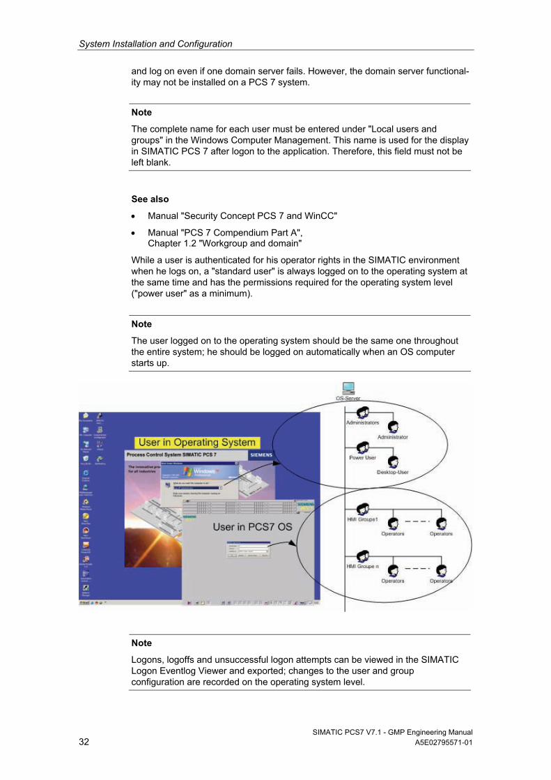
While a user is authenticated for his operator rights in the SIMATIC environment when he logs on, a "standard user" is always logged on to the operating system at the same time and has the permissions required for the operating system level ("power user" as a minimum).
Note
The user logged on to the operating system should be the same one throughout the entire system; he should be logged on automatically when an OS computer starts up.
Note
Logons, logoffs and unsuccessful logon attempts can be viewed in the SIMATIC Logon Eventlog Viewer and exported; changes to the user and group configuration are recorded on the operating system level.
System Installation and Configuration
SIMATIC PCS7 V7.1 - GMP Engineering Manual A5E02795571-01 33
4.3.2 Security settings in Windows
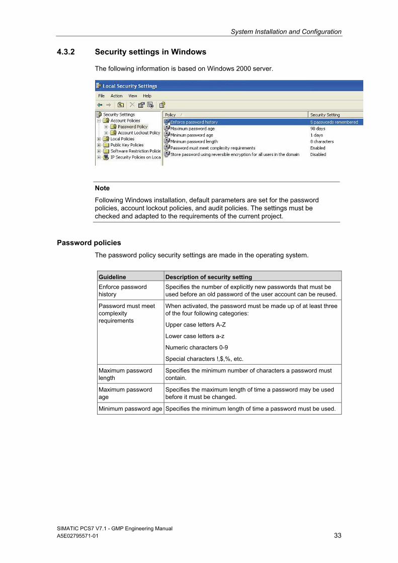
The following information is based on Windows 2000 server.
Note
Following Windows installation, default parameters are set for the password policies, account lockout policies, and audit policies. The settings must be checked and adapted to the requirements of the current project.
Password policies
The password policy security settings are made in the operating system.
Guideline Description of security setting
Enforce password history
Specifies the number of explicitly new passwords that must be used before an old password of the user account can be reused.
Password must meet complexity requirements
When activated, the password must be made up of at least three of the four following categories:
Upper case letters A-Z
Lower case letters a-z
Numeric characters 0-9
Special characters !,$,%, etc.
Maximum password length
Specifies the minimum number of characters a password must contain.
Maximum password age
Specifies the maximum length of time a password may be used before it must be changed.
Minimum password age Specifies the minimum length of time a password must be used.
System Installation and Configuration
SIMATIC PCS7 V7.1 - GMP Engineering Manual 34 A5E02795571-01
Account lockout policies
The security mechanisms for account lockout policies, such as the number of permissible failed logon attempts, are set in the operating system.
Guideline Description of security setting
Account lockout threshold Specifies the number of failed attempted logons before the user account is locked out.
Account lockout duration Specifies how long an account is to remain locked out before the lockout is lifted automatically. If the value is set to 0, the account will remain locked out until it has been explicitly released by an administrator. This is the recommended setting.
Reset account lockout counter after
Specifies how many minutes must elapse after failed logon attempts before the account lockout counter is reset again.
Audit policies
The security mechanisms for audit policies relating to logon attempts, account management activities, etc. are set in the operating system.
Guideline Description of security setting
Audit logon attempts Specifies whether or not the instance of a user logging on to a computer is audited.
Audit account management
Specifies whether or not the individual events of account management are audited (creating or changing a user account, changing or setting passwords).
Audit logon events Specifies whether each instance of a user who has logged onto or logged off a computer will be audited.
Audit policy change Specifies whether or not changes to user rights policies, audit policies, or trust policies are to be audited.
Note
In order to enable logon activities to be traced at a later date, the required settings must be made in the audit policy of the local policies of Window, as well as those in SIMATIC Logon as described in chapter 4.3.4 “Configuring SIMATIC Logon”.
4.3.3 SIMATIC user groups
When PCS 7 is installed, default SIMATIC user groups are automatically created in the operating system (SIMATIC HMI, etc.). These must not be changed or deleted.
See also
Manual "Security Concept PCS 7 and WinCC"
System Installation and Configuration
SIMATIC PCS7 V7.1 - GMP Engineering Manual A5E02795571-01 35
Note
The defined users and user groups must be made members of the SIMATIC user groups which have the appropriate authorization.
4.3.4 Configuring SIMATIC Logon
The basic settings for configuring SIMATIC Logon are made with the "Configure SIMATIC Logon" dialog. The available settings are described in "SIMATIC Logon" configuration manual.
Note
Events, such as successful and failed logons and logoffs, password changes, etc. are stored in the EventLog database of SIMATIC Logon. This must be taken into account when backing up data.
Automatic logoff (Auto-Logoff)
To prevent the logged on user from accessing parts of the system for which he is not authorized, the "Auto-Logoff" function must be enabled in the SIMATIC Logon configuration for a defined period of time.
Note
The "Auto-Logoff" function must be disabled on the operating system level, otherwise the user interface will close down completely.
A screen saver should also be disabled when SIMATIC Logon is used.
Default user after user logs off
In the "General" tab, you can define whether a default user should be logged on after a user logs off.
Unlike all other users, the "Default User" user does not have to be created as a Windows user. The "Default User" is a member of the "DefaultGroup" and "Emer-gency_Operator" roles. The permissions assigned to these groups are specified in the respective PCS 7 OS (server/client) applications.
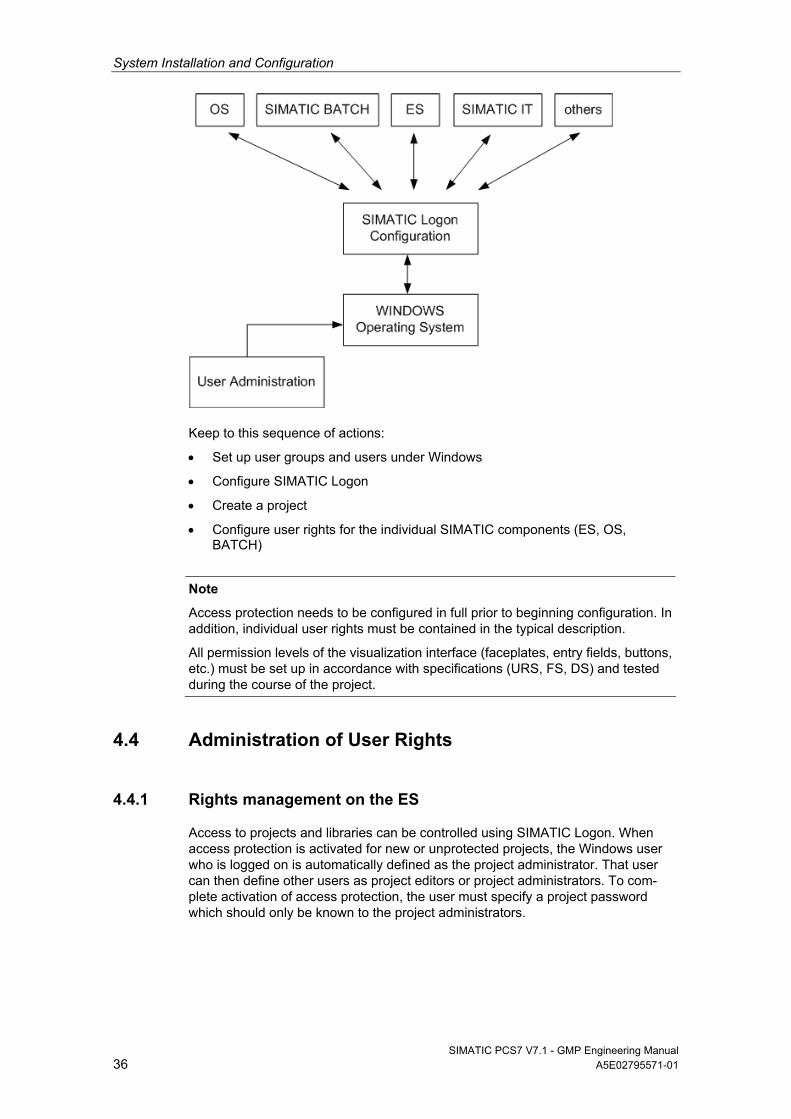
4.3.5 How access protection works
SIMATIC Logon Service must be installed in order to enable access protection. SIMATIC Logon maintains users and user groups by means of the operating system’s user administration. The rights of the various users (user groups) to operator actions and the way in which they are logged on to the system are assigned on the operator control level in SIMATIC OS and SIMATIC BATCH and on the engineering level in SIMATIC ES, according to the system specification.
System Installation and Configuration
SIMATIC PCS7 V7.1 - GMP Engineering Manual 36 A5E02795571-01
Keep to this sequence of actions:
Set up user groups and users under Windows
Configure SIMATIC Logon
Create a project
Configure user rights for the individual SIMATIC components (ES, OS, BATCH)
Note
Access protection needs to be configured in full prior to beginning configuration. In addition, individual user rights must be contained in the typical description.
All permission levels of the visualization interface (faceplates, entry fields, buttons, etc.) must be set up in accordance with specifications (URS, FS, DS) and tested during the course of the project.
4.4 Administration of User Rights
4.4.1 Rights management on the ES
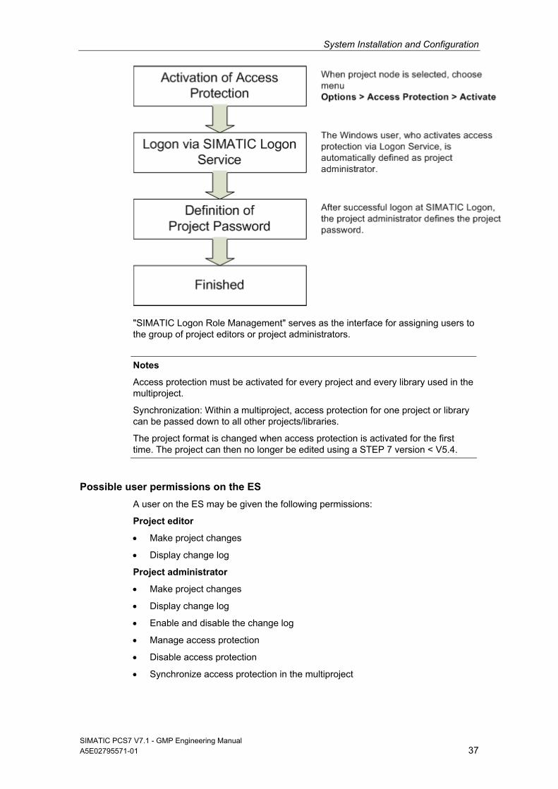
Access to projects and libraries can be controlled using SIMATIC Logon. When access protection is activated for new or unprotected projects, the Windows user who is logged on is automatically defined as the project administrator. That user can then define other users as project editors or project administrators. To com-plete activation of access protection, the user must specify a project password which should only be known to the project administrators.
System Installation and Configuration
SIMATIC PCS7 V7.1 - GMP Engineering Manual A5E02795571-01 37
"SIMATIC Logon Role Management" serves as the interface for assigning users to the group of project editors or project administrators.
Notes
Access protection must be activated for every project and every library used in the multiproject.
Synchronization: Within a multiproject, access protection for one project or library can be passed down to all other projects/libraries.
The project format is changed when access protection is activated for the first time. The project can then no longer be edited using a STEP 7 version < V5.4.
Possible user permissions on the ES
A user on the ES may be given the following permissions:
Project editor
Make project changes
Display change log
Project administrator
Make project changes
Display change log
Enable and disable the change log
Manage access protection
Disable access protection
Synchronize access protection in the multiproject
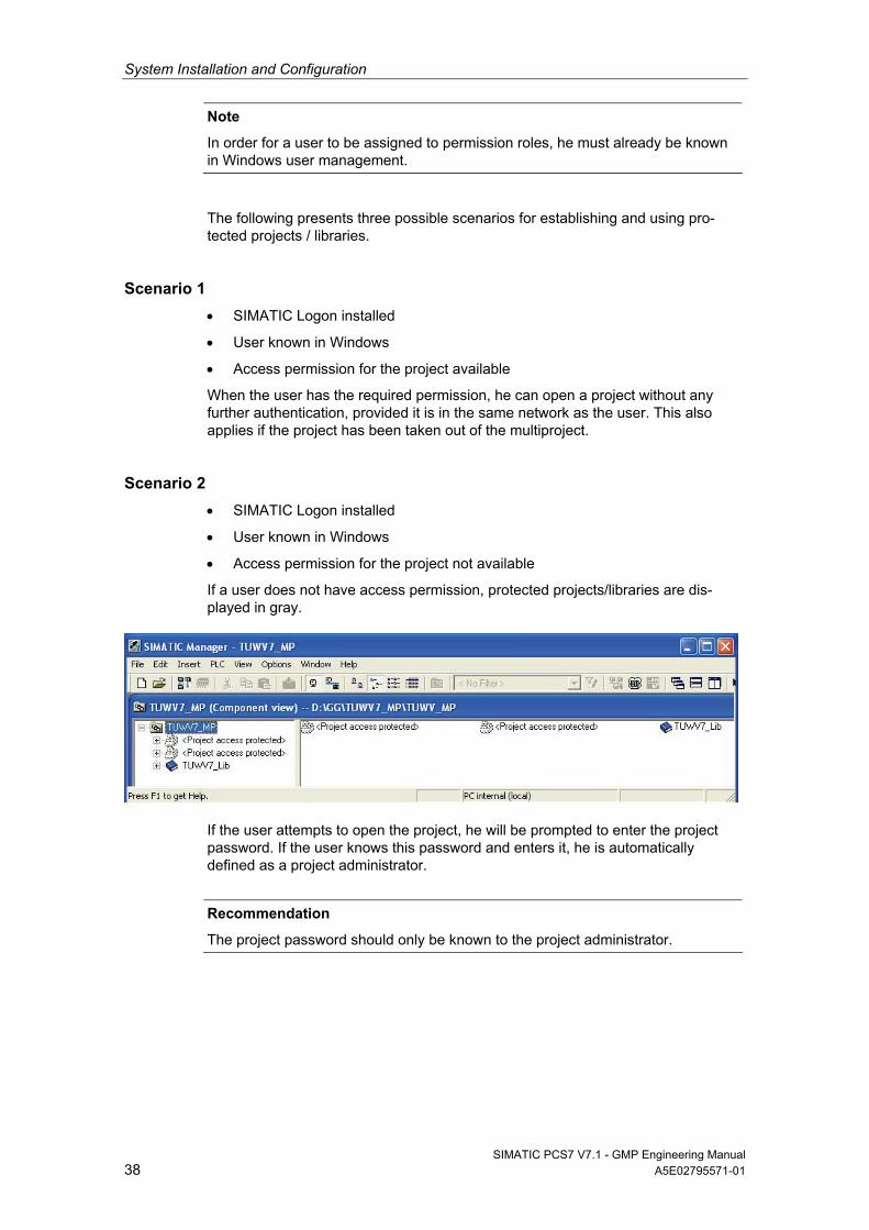
System Installation and Configuration
SIMATIC PCS7 V7.1 - GMP Engineering Manual 38 A5E02795571-01
Note
In order for a user to be assigned to permission roles, he must already be known in Windows user management.
The following presents three possible scenarios for establishing and using pro-tected projects / libraries.
Scenario 1
SIMATIC Logon installed
User known in Windows
Access permission for the project available
When the user has the required permission, he can open a project without any further authentication, provided it is in the same network as the user. This also applies if the project has been taken out of the multiproject.
Scenario 2
SIMATIC Logon installed
User known in Windows
Access permission for the project not available
If a user does not have access permission, protected projects/libraries are dis-played in gray.
If the user attempts to open the project, he will be prompted to enter the project password. If the user knows this password and enters it, he is automatically defined as a project administrator.
Recommendation
The project password should only be known to the project administrator.
System Installation and Configuration
SIMATIC PCS7 V7.1 - GMP Engineering Manual A5E02795571-01 39
Scenario 3
SIMATIC Logon not installed
If SIMATIC Logon is not installed, there is no project administration function. Each time a protected project/library is opened, the project password must be entered. Also in this case, the project password should only be known by the relevant group of people. If the protected project has been provided by a customer, they must decide whether or not the existing password should be changed in their system.
Recommendation
The way in which the project password is used and the time at which access protection is to be activated on the ES level should be given careful consideration and defined at an early stage.
See also
Configuration manual “PCS 7 Engineering System”
4.4.2 Rights management on the OS
Windows user groups are assigned to PCS 7 OS groups by creating groups of the same names. For example, if you want to assign an "Operator" Windows group, an identically named "Operator" group must be created in the PCS 7 OS User Administration and the required rights assigned. The following procedure must be followed for this:
Open PCS 7 OS project
Open user management via WinCC Control Center
Create the group(s)
Assign the permissions for each group
The figure below shows how operator rights are assigned to individual groups.
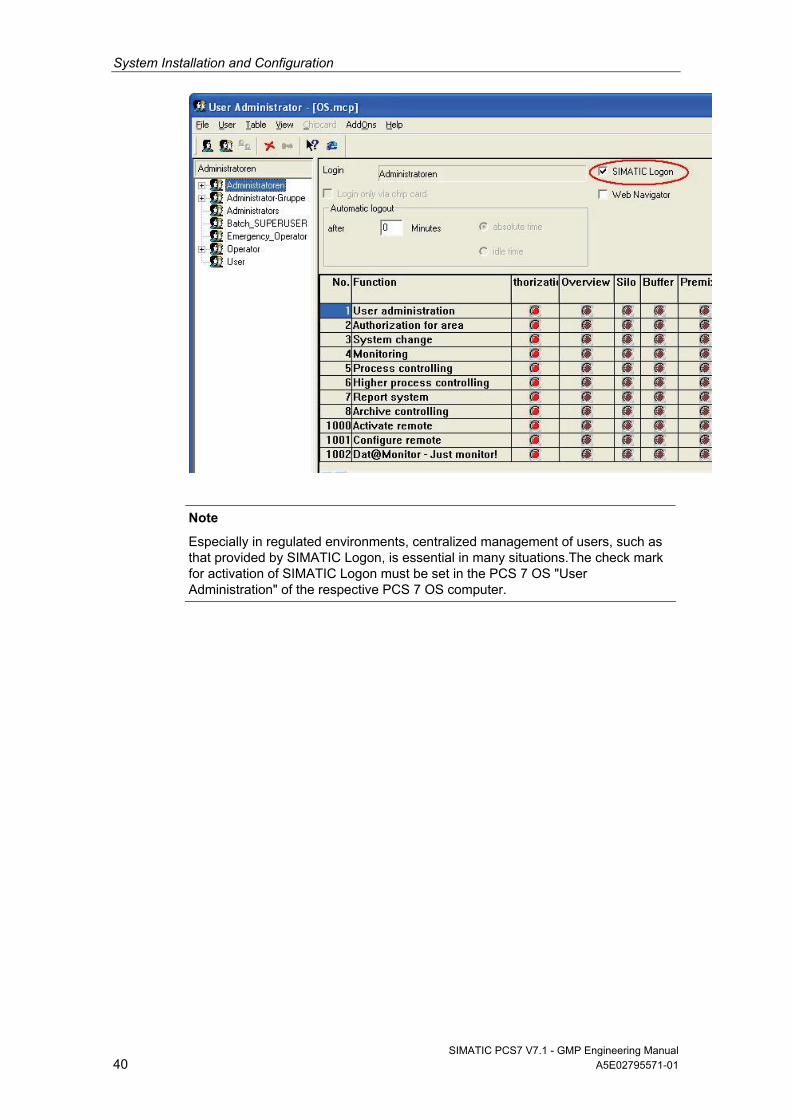
System Installation and Configuration
SIMATIC PCS7 V7.1 - GMP Engineering Manual 40 A5E02795571-01
Note
Especially in regulated environments, centralized management of users, such as that provided by SIMATIC Logon, is essential in many situations.The check mark for activation of SIMATIC Logon must be set in the PCS 7 OS "User Administration" of the respective PCS 7 OS computer.
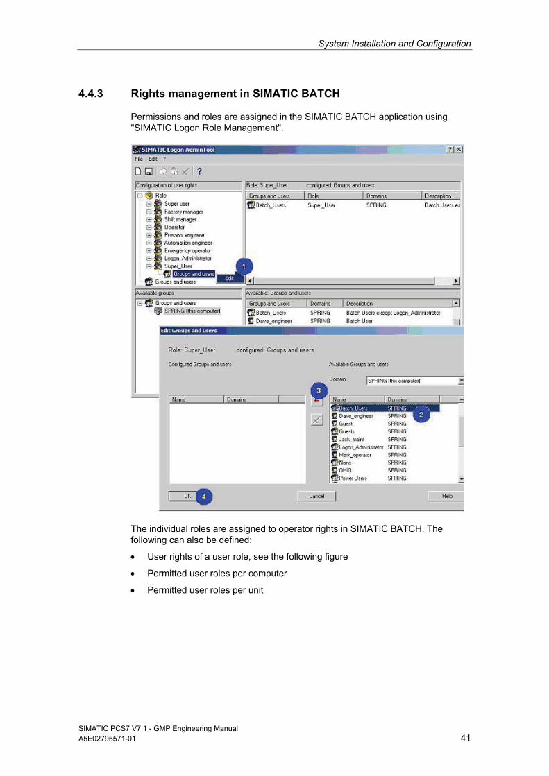
System Installation and Configuration
SIMATIC PCS7 V7.1 - GMP Engineering Manual A5E02795571-01 41
4.4.3 Rights management in SIMATIC BATCH
Permissions and roles are assigned in the SIMATIC BATCH application using "SIMATIC Logon Role Management".
The individual roles are assigned to operator rights in SIMATIC BATCH. The following can also be defined:
User rights of a user role, see the following figure
Permitted user roles per computer
Permitted user roles per unit
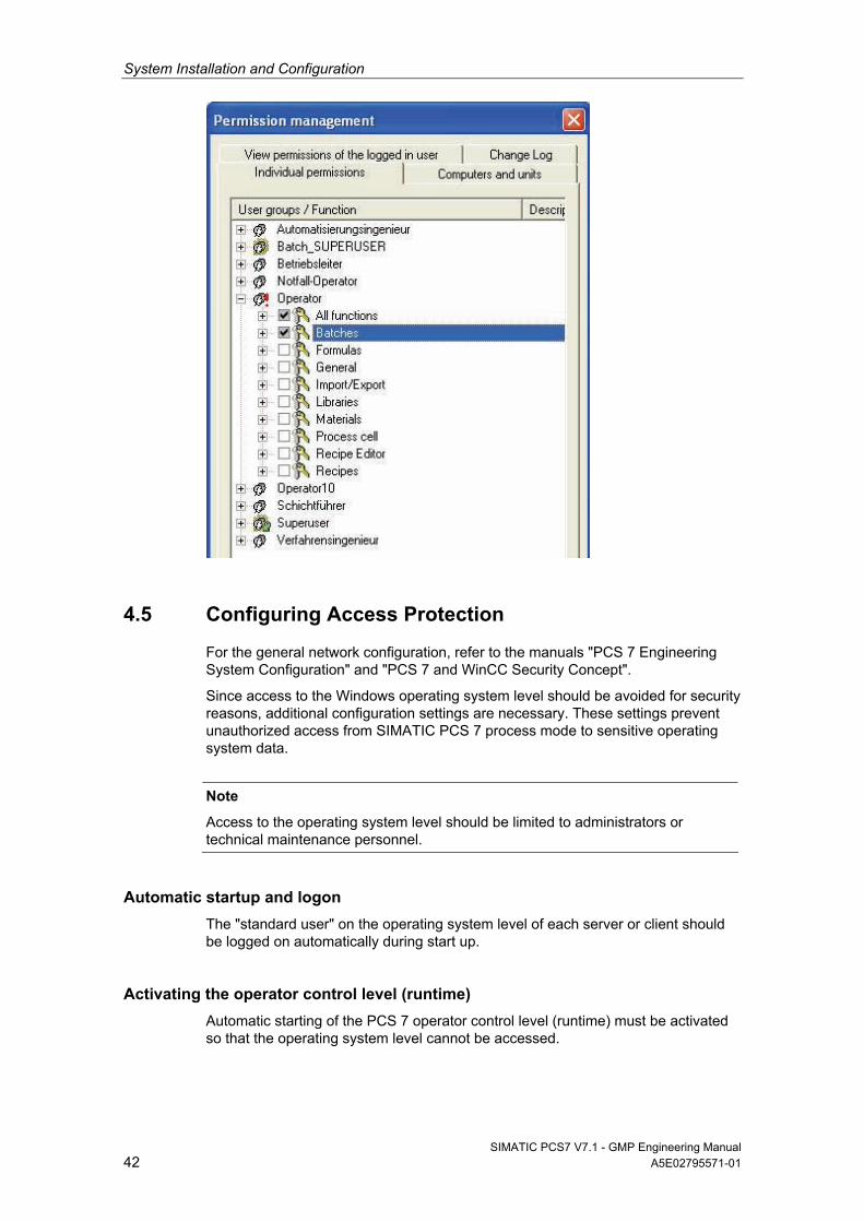
System Installation and Configuration
SIMATIC PCS7 V7.1 - GMP Engineering Manual 42 A5E02795571-01
4.5 Configuring Access Protection
For the general network configuration, refer to the manuals "PCS 7 Engineering System Configuration" and "PCS 7 and WinCC Security Concept".
Since access to the Windows operating system level should be avoided for security reasons, additional configuration settings are necessary. These settings prevent unauthorized access from SIMATIC PCS 7 process mode to sensitive operating system data.
Note
Access to the operating system level should be limited to administrators or technical maintenance personnel.
Automatic startup and logon
The "standard user" on the operating system level of each server or client should be logged on automatically during start up.
Activating the operator control level (runtime)
Automatic starting of the PCS 7 operator control level (runtime) must be activated so that the operating system level cannot be accessed.
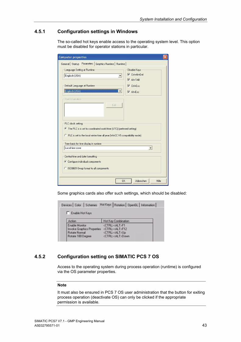
System Installation and Configuration
SIMATIC PCS7 V7.1 - GMP Engineering Manual A5E02795571-01 43
4.5.1 Configuration settings in Windows
The so-called hot keys enable access to the operating system level. This option must be disabled for operator stations in particular.
Some graphics cards also offer such settings, which should be disabled:
4.5.2 Configuration setting on SIMATIC PCS 7 OS
Access to the operating system during process operation (runtime) is configured via the OS parameter properties.
Note
It must also be ensured in PCS 7 OS user administration that the button for exiting process operation (deactivate OS) can only be clicked if the appropriate permission is available.
System Installation and Configuration
SIMATIC PCS7 V7.1 - GMP Engineering Manual 44 A5E02795571-01
4.5.3 Secure configuration
If possible, no OLE objects should be configured, as such objects often allow unauthorized access to folders, files, and programs.
4.6 Information Security
4.6.1 SIMATIC Security Control (SSC)
Using SIMATIC Security Control increases the level of computer security. The application can be run either when PCS 7 installation is completed or at a later point in time. The following settings are configured automatically for specific functions (OS client/server, ES, etc.):
Configuration of the Windows Firewall exception list for PCS 7 communication (firewall can be activated)
DCOM settings for PCS 7 (Distributed Component Object Model)
Security-related registry entries
Following installation, the Start > SIMATIC > SimaticSecurityControl menu com-mand can be used to perform configuration at any time. SSC also enables the settings made in the system to be documented.
Note
If the SIMATIC PC station is integrated into a different working environment (domain or workgroup), it must be reconfigured.
4.6.2 SCALANCE S
The increasing integration of plant networks into office networks brings with it a rise in associated security risks, from network problems such as the duplicate assign-ment of network addresses, to problems with viruses, and even the possibility of attacks by computer hackers.
In certain applications, the SCALANCE S security modules can be used to coun-teract these risks. They basically offer two different functions:
Firewall
If a firewall is used, only registered nodes can communicate over the network.
See also
Product Support http://support.automation.siemens.com/DE, FAQs on the topic "Communication/Networks"
Product Support http://support.automation.siemens.com/DE/view/de/22376747 "Protection of an Automation Cell using the Security Module SCALANCE S602 via Firewall" and the document attached there
System Installation and Configuration
SIMATIC PCS7 V7.1 - GMP Engineering Manual A5E02795571-01 45
VPN
A virtual private network (VPN) links external computers to the local network and is also capable of encrypting the transferred data. A VPN connection enables external systems to perform secure remote access over the Internet. To do this, SCALANCE S technology uses the IPSec protocol, which provides an extremely high level of security in tunnel mode (VPN tunnel).
See also
Product Support http://support.automation.siemens.com/DE, FAQs on the topic "Communication/Networks"
Product Support http://support.automation.siemens.com/DE/view/de/22056713 "Industrial Security with SCALANCE S Modules Over IPSec VPN Tunnels" and the document attached there
Note
SCALANCE S technology offers various applications. More information can be found in the manuals of the SCALANCE product series.
Project Settings and Definitions
SIMATIC PCS7 V7.1 - GMP Engineering Manual 46 A5E02795571-01
5 Project Settings and Definitions
5.1 Multiproject Setup
Multiproject engineering allows a project to be divided into several sub-projects so that it can be worked on by more than one person. A higher-level "multiproject", which contains the individual projects (AS, OS, SIMATIC BATCH) and the master data library, is defined in the SIMATIC Manager. Projects can be added to and removed from the multiproject. The master data library supports consistent data management within the multiproject.
Note
In a controlled environment in particular, it is essential to use the master data library to centrally manage process tag types, models, SFC types, and shared declarations.
The SIMATIC PCS 7 "New project" wizard assists you in creating projects. It automatically creates a multiproject. The project name to be assigned must be previously defined in the software specification, as it can be difficult to subse-quently rename a project.
See also
Manual "PCS 7 Compendium Part A", chapter 2.2 "Required settings in the SIMATIC Manager" and 2.3 "Automatically creating a multiproject"
A new (sub-)project can be added to an existing multiproject as an empty or a preconfigured project:
For projects whose size means they are suitable candidates for division into several multiprojects, the project structure and modes of operation must be carefully planned and documented. Your usual Service & Support contacts would be happy to assist you with this.
5.2 Referenced OS Stations
Using a referenced OS station allows you to create a reference to an existing OS station. Several OS types can be configured as samples and all other OS stations derived from these samples, similar to the way the type/instance concept works.
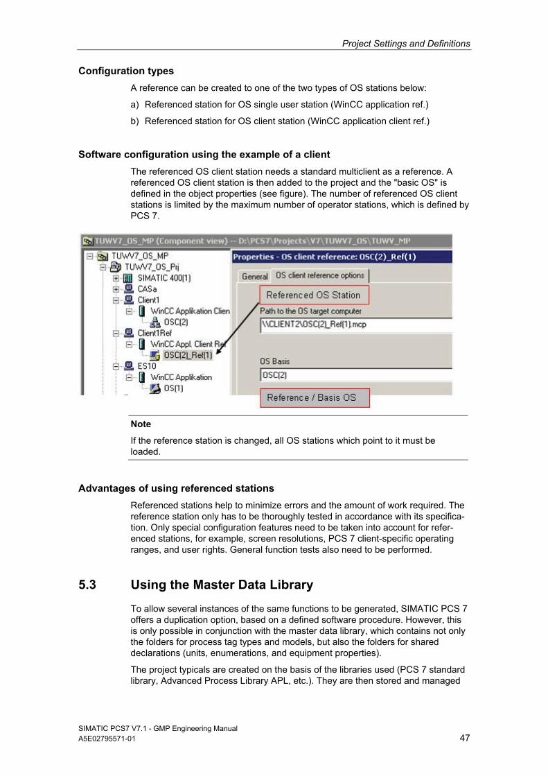
Project Settings and Definitions
SIMATIC PCS7 V7.1 - GMP Engineering Manual A5E02795571-01 47
Configuration types
A reference can be created to one of the two types of OS stations below:
a) Referenced station for OS single user station (WinCC application ref.)
b) Referenced station for OS client station (WinCC application client ref.)
Software configuration using the example of a client
The referenced OS client station needs a standard multiclient as a reference. A referenced OS client station is then added to the project and the "basic OS" is defined in the object properties (see figure). The number of referenced OS client stations is limited by the maximum number of operator stations, which is defined by PCS 7.
Note
If the reference station is changed, all OS stations which point to it must be loaded.
Advantages of using referenced stations
Referenced stations help to minimize errors and the amount of work required. The reference station only has to be thoroughly tested in accordance with its specifica-tion. Only special configuration features need to be taken into account for refer-enced stations, for example, screen resolutions, PCS 7 client-specific operating ranges, and user rights. General function tests also need to be performed.
5.3 Using the Master Data Library
To allow several instances of the same functions to be generated, SIMATIC PCS 7 offers a duplication option, based on a defined software procedure. However, this is only possible in conjunction with the master data library, which contains not only the folders for process tag types and models, but also the folders for shared declarations (units, enumerations, and equipment properties).
The project typicals are created on the basis of the libraries used (PCS 7 standard library, Advanced Process Library APL, etc.). They are then stored and managed
Project Settings and Definitions
SIMATIC PCS7 V7.1 - GMP Engineering Manual 48 A5E02795571-01
in the master data library. The PCS 7 standard libraries include templates that can be used.
Recommendation
The modules and typicals must be verified with a module test and approved by the customer prior to instantiation.
Not only must the same versions of faceplates, SFC types, and typicals be used in all projects within a multiproject, but such projects must also be based on a common plant hierarchy and shared declarations. The individual projects must be synchronized with the master data library for this.
See also
Product Support http://support.automation.siemens.com/DE, FAQs
Product Support http://support.automation.siemens.com/DE/view/de/22258951 "Multiproject Engineering"
Product Support http://support.automation.siemens.com/DE/view/de/23785345 "Multiproject Engineering with SIMATIC BATCH"
Note
SIMATIC Version Trail is used to clearly archive and organize versions of the master data library during the course of the project.
The faceplates, SFC types, and shared declarations are the smallest user software modules. These are used in creating process tag types and models, which are then duplicated either manually or via the IEA interface , see also chapter 6.2 "Bulk Engineering with the IEA" for more on this.
See also
Manual "PCS 7 Compendium Part A", chapter 5.2.1 "Process tag types (templates)"
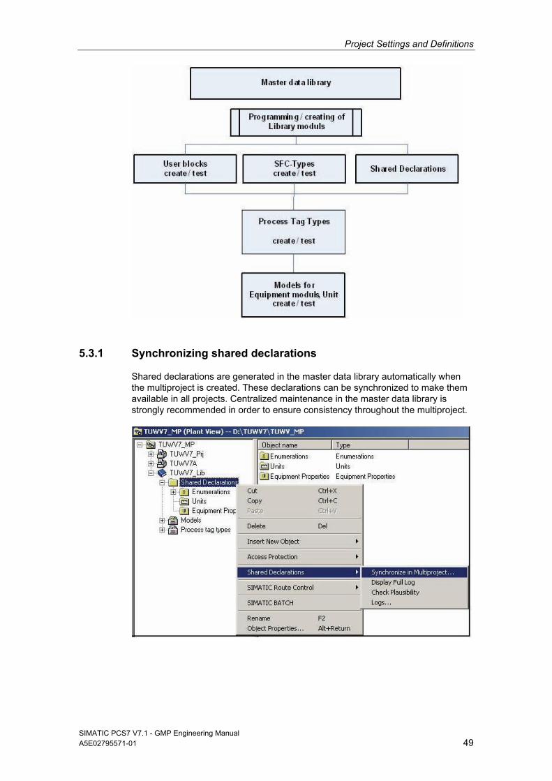
Project Settings and Definitions
SIMATIC PCS7 V7.1 - GMP Engineering Manual A5E02795571-01 49
5.3.1 Synchronizing shared declarations
Shared declarations are generated in the master data library automatically when the multiproject is created. These declarations can be synchronized to make them available in all projects. Centralized maintenance in the master data library is strongly recommended in order to ensure consistency throughout the multiproject.
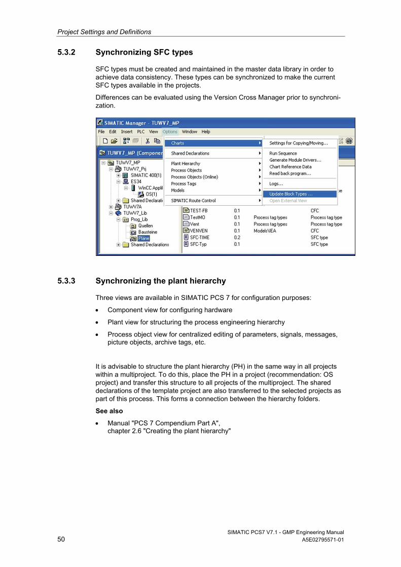
Project Settings and Definitions
SIMATIC PCS7 V7.1 - GMP Engineering Manual 50 A5E02795571-01
5.3.2 Synchronizing SFC types
SFC types must be created and maintained in the master data library in order to achieve data consistency. These types can be synchronized to make the current SFC types available in the projects.
Differences can be evaluated using the Version Cross Manager prior to synchroni-zation.
5.3.3 Synchronizing the plant hierarchy
Three views are available in SIMATIC PCS 7 for configuration purposes:
Component view for configuring hardware
Plant view for structuring the process engineering hierarchy
Process object view for centralized editing of parameters, signals, messages, picture objects, archive tags, etc.
It is advisable to structure the plant hierarchy (PH) in the same way in all projects within a multiproject. To do this, place the PH in a project (recommendation: OS project) and transfer this structure to all projects of the multiproject. The shared declarations of the template project are also transferred to the selected projects as part of this process. This forms a connection between the hierarchy folders.
See also
Manual "PCS 7 Compendium Part A", chapter 2.6 "Creating the plant hierarchy"
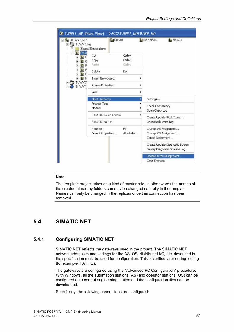
Project Settings and Definitions
SIMATIC PCS7 V7.1 - GMP Engineering Manual A5E02795571-01 51
Note
The template project takes on a kind of master role, in other words the names of the created hierarchy folders can only be changed centrally in the template. Names can only be changed in the replicas once this connection has been removed.
5.4 SIMATIC NET
5.4.1 Configuring SIMATIC NET
SIMATIC NET reflects the gateways used in the project. The SIMATIC NET network addresses and settings for the AS, OS, distributed I/O, etc. described in the specification must be used for configuration. This is verified later during testing (for example, FAT, IQ).
The gateways are configured using the "Advanced PC Configuration" procedure. With Windows, all the automation stations (AS) and operator stations (OS) can be configured on a central engineering station and the configuration files can be downloaded.
Specifically, the following connections are configured:
Project Settings and Definitions
SIMATIC PCS7 V7.1 - GMP Engineering Manual 52 A5E02795571-01
AS/OS connections
AS/AS connections
ES/AS connections
Remote I/O connections
These connections can also be designed to be fault-tolerant.
More information can be found in the SIMATIC NET documentation.
5.4.2 Plant bus and terminal bus
Industrial Ethernet offers a comprehensive range of network components for electrical and optical data transmission. In SIMATIC PCS 7, a distinction is made between a plant bus and a terminal bus. To guarantee a high degree of security and performance, it is advisable to install these two buses separately.
Industrial Ethernet plant bus
Industrial Ethernet is used as the plant bus. The Industrial Ethernet network operates according to the access method CSMA/CD (Carrier sense multiple access with collision detection) as defined in IEEE 802.3.
The automation stations are connected with the OS servers and the engineering station over the plant bus. The ISO protocol is generally used as the transport protocol.
See also
Manual "PCS 7 Compendium Part A", chapter 1.3.2 "Configuring the plant bus"
Ethernet terminal bus
The PCS 7 servers are connected with the clients, archive servers, and higher-level MES systems over the terminal bus. The TCP/IP protocol is normally used as the transport protocol.
See also
Manual "PCS 7 Compendium Part A", chapter 1.3.1 "Configuring the terminal bus"
5.4.3 PROFIBUS
Reliable communication with the field level must be in place in order to ensure trouble-free plant operation. Such communication is based on a high-performance real-time bus system such as PROFIBUS versions DP and PA.
See also
System manual "SIMATIC NET PROFIBUS Network Manual"
Manual "PCS 7 Engineering System (V7.1)", chapter 4.5.6 "Fieldbus with PROFIBUS"
Manual "PCS 7 Compendium Part A", chapter 3.4 "PROFIBUS settings on the CP 443-5 Ext"
Project Settings and Definitions
SIMATIC PCS7 V7.1 - GMP Engineering Manual A5E02795571-01 53
Note
The configuration of the PROFIBUS devices/communication is integrated into the overall project in the SIMATIC Manager. A backup of the engineering project therefore contains the entire user software. This has corresponding advantages in terms of regular data backups and verification of the software within the framework of the test phases.
PROFIBUS DP
Remote I/O stations such as ET 200 can have a simple or a redundant design over electrical or optical PROFIBUS DP networks.
With the help of an isolating transformer (RS 485iS coupler) used as a barrier and the intrinsically safe ET 200iSP, PROFIBUS DP can even be used in hazardous zone 1. This makes data transfer rates of up to 1.5 Mbps possible, even in hazard-ous areas.
Complex process I/O devices such as those listed below can be linked to PCS 7 using predefined add-on blocks:
SIMOCODE pro motor management system
MICROMASTER 4 frequency inverters
SIWAREX weighing system
Also available:
Function modules (e.g. closed-loop controllers, motor starters, etc.)
HART modules (for integrating HART field devices)
F-modules (for fail-safe applications)
Ex modules (connection of actuators/sensors from zone 0 or 1)
All HART modules can be configured via the PDM, see chapter 5.4.4 "SIMATIC PDM".
PROFIBUS PA
Profibus PA can also be easily implemented or designed redundant.
See also
Operating instructions "Bus links DP/PA coupler, DP/PA link and Y link"
Note
When configured as a diagnostic slave, the FDC 157-0 DP/PA coupler is fully integrated into plant-level PCS 7 Asset Management.
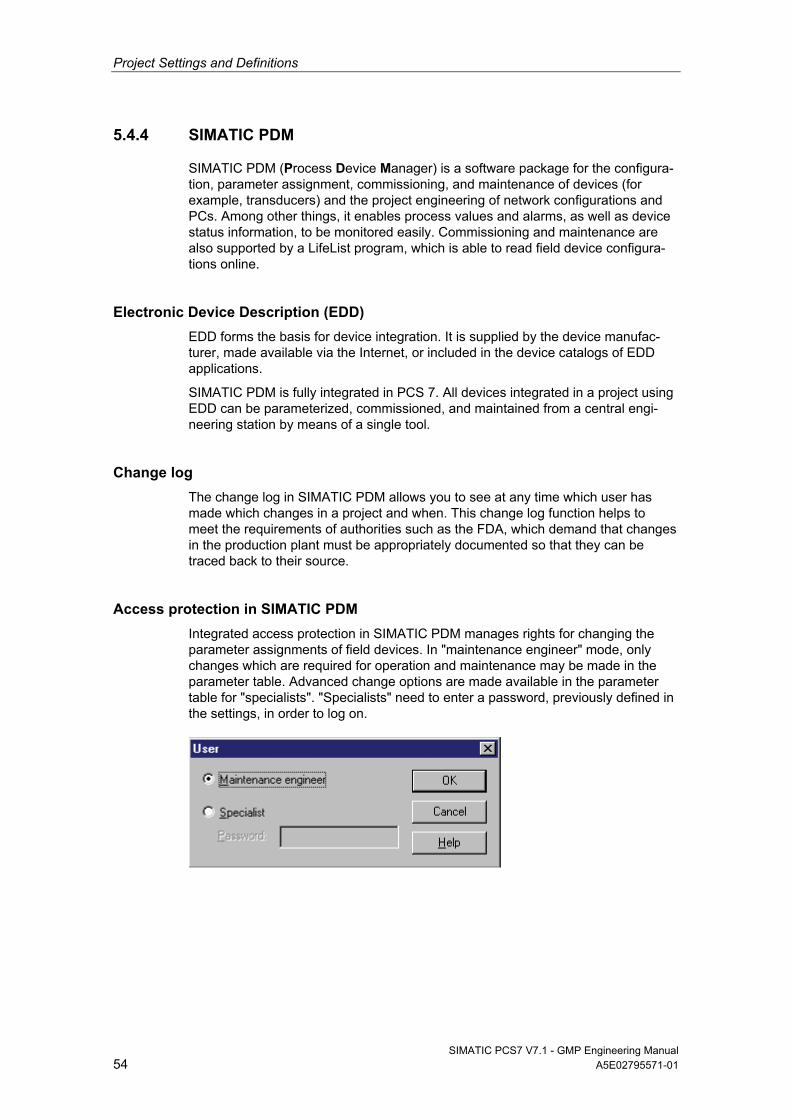
Project Settings and Definitions
SIMATIC PCS7 V7.1 - GMP Engineering Manual 54 A5E02795571-01
5.4.4 SIMATIC PDM
SIMATIC PDM (Process Device Manager) is a software package for the configura-tion, parameter assignment, commissioning, and maintenance of devices (for example, transducers) and the project engineering of network configurations and PCs. Among other things, it enables process values and alarms, as well as device status information, to be monitored easily. Commissioning and maintenance are also supported by a LifeList program, which is able to read field device configura-tions online.
Electronic Device Description (EDD)
EDD forms the basis for device integration. It is supplied by the device manufac-turer, made available via the Internet, or included in the device catalogs of EDD applications.
SIMATIC PDM is fully integrated in PCS 7. All devices integrated in a project using EDD can be parameterized, commissioned, and maintained from a central engi-neering station by means of a single tool.
Change log
The change log in SIMATIC PDM allows you to see at any time which user has made which changes in a project and when. This change log function helps to meet the requirements of authorities such as the FDA, which demand that changes in the production plant must be appropriately documented so that they can be traced back to their source.
Access protection in SIMATIC PDM
Integrated access protection in SIMATIC PDM manages rights for changing the parameter assignments of field devices. In "maintenance engineer" mode, only changes which are required for operation and maintenance may be made in the parameter table. Advanced change options are made available in the parameter table for "specialists". "Specialists" need to enter a password, previously defined in the settings, in order to log on.
Project Settings and Definitions
SIMATIC PCS7 V7.1 - GMP Engineering Manual A5E02795571-01 55
Export functions in SIMATIC PDM
In SIMATIC PDM, the following field device data can be backed up via an export procedure:
Device parameters
Change log, changes sorted according to object
Calibration report, contains information relating to commissioning and mainte-nance, as well as test results
Note
Version information can be saved in the device’s comment field. This information is then exported together with the device data. In addition, a version can be identified by the name given to the export file.
As the export file contains a reference to an appropriate transformation file, the content of the export file is displayed in the Web browser in a readable HTML format. The corresponding transformation file ("PDMExportEddl.XSL" for the device parameters and change log or "PDMExportCalibration.XSL" for the calibration report) is copied to the export file location as part of the export procedure.
Note
If the export file is copied to a different directory or computer and the HTML display is to be used, the corresponding transformation file must also be copied.
5.4.5 FOUNDATION Fieldbus (FF)
As well as facilitating communication via PROFIBUS or HART, SIMATIC PCS 7 also offers interfaces for FOUNDATION Fieldbus (H1), allowing a wide range of FF instruments and positioners to be integrated into the process control system. The FOUNDATION Fieldbus H1 is connected to PROFIBUS DP via the DP/FF link.
This concept offers:
Central engineering of the DP/FF link and FF field devices without the need for additional tools
FF drivers in the PCS 7 library and the support of the driver wizard
Integration in PCS 7 Asset Management
Cyclic and acyclic communication
Cyclic diagnostic information provided by the DP/FF link and the FF field devices
See also
Manual "DP/FF Link"
Project Settings and Definitions
SIMATIC PCS7 V7.1 - GMP Engineering Manual 56 A5E02795571-01
Diagnostics with PCS 7 Asset Management
A diagnostic symbol is created on the PROFIBUS DP device level in the diagnostic area for each AnyBus DP link. It is advisable to insert a status indicator and a button for switching to the user diagnostics of the connected FF field devices for each AnyBus DP link.
Configuration and diagnostics via the Web interface
The connected FF field devices are configured and diagnosed via the supplied web interface.
5.5 OS Project Editor
The OS Project Editor serves as the basic tool for configuring the user interface, for example, for setting the screen layout, screen resolution, etc.
When an OS project is created in the SIMATIC PCS 7 ES, the OS Project Editor is initialized with the default settings.
Many of these default settings can and should be retained in projects. Any devia-tions must be defined in the specification and require very special attention in every update of the system.
Some settings are always project-specific. These settings and any changes in response to customer requirements are defined in the specification.
The layout of the runtime is configured in the "Layout" tab. This includes the screen formats, number of monitors per OS station and the display of the user name or user ID in runtime.
Message classes, message types, message blocks, and the PCS 7 standard messages are configured in the "Message configuration" tab.
Messaging response is configured in the "Message display" tab. This includes the display of messages in the message pages and the group display, mes-sage filters and Smart Alarm Hiding.
Under "Area" the representation of area and server keys (for example, process cell, unit, functions, etc.) are configured for the overview area.
The number and arrangement of picture windows is configured in the "Runtime window" tab. The pictures (graphics) and faceplates are opened in the runtime in the picture windows.
In the "Basic data" tab, you can specify which modified files of the project are to be overwritten by factory state files. However, you should always ensure when making this configuration change that runtime operation remains consis-tent and safe.
The "General" tab contains settings for the OS Project Editor.
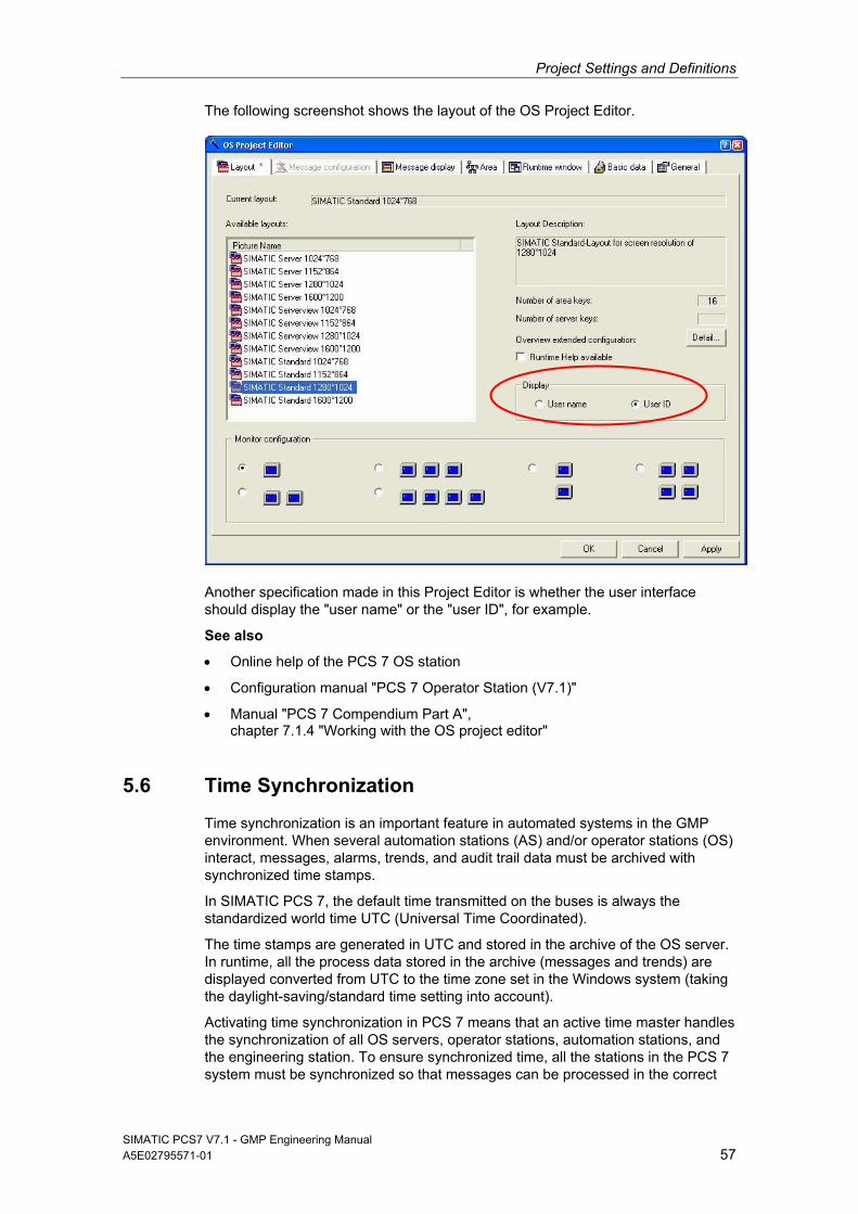
Project Settings and Definitions
The following screenshot shows the layout of the OS Project Editor.
Another specification made in this Project Editor is whether the user interface should display the "user name" or the "user ID", for example.
See also
• Online help of the PCS 7 OS station
• Configuration manual "PCS 7 Operator Station (V7.1)"
• Manual "PCS 7 Compendium Part A", chapter 7.1.4 "Working with the OS project editor"
5.6 Time Synchronization
Time synchronization is an important feature in automated systems in the GMP environment. When several automation stations (AS) and/or operator stations (OS) interact, messages, alarms, trends, and audit trail data must be archived with synchronized time stamps.
In SIMATIC PCS 7, the default time transmitted on the buses is always the standardized world time UTC (Universal Time Coordinated).
The time stamps are generated in UTC and stored in the archive of the OS server. In runtime, all the process data stored in the archive (messages and trends) are displayed converted from UTC to the time zone set in the Windows system (taking the daylight-saving/standard time setting into account).
Activating time synchronization in PCS 7 means that an active time master handles the synchronization of all OS servers, operator stations, automation stations, and the engineering station. To ensure synchronized time, all the stations in the PCS 7 system must be synchronized so that messages can be processed in the correct
SIMATIC PCS7 V7.1 - GMP Engineering Manual A5E02795571-01 57
Project Settings and Definitions
SIMATIC PCS7 V7.1 - GMP Engineering Manual 58 A5E02795571-01
chronological order throughout the plant (archiving of trends, messages, redun-dancy synchronization of servers).
Time synchronization in a Windows work group:
In a workgroup environment, the plant bus is synchronized via the central plant clock (SICLOCK, for example). The OS servers obtain the time from the plant bus; they are configured as "cooperative time masters". If no SICLOCK timer is avail-able, an OS server becomes the active time master. The automation stations obtain the time from SICLOCK; they are configured as time slaves. The OS clients obtain the time from an OS server; they only receive the time from OS servers whose server data they have also loaded.
Time synchronization in a Windows domain
If the automation system is operated in a Windows domain, the domain controller with the PDC role serves as the time master on the terminal bus. It obtains its time from a SICLOCK connected in series, for example. The OS servers receive the time from this domain controller via the terminal bus. The OS clients obtain the time from a selected OS sever. The plant bus and, as a result, the connected automa-tion stations (AS) are also synchronized by this OS server (the first server to enter process mode). The server then becomes the active time master.
When high-precision time stamping is required, the automation stations also have to be synchronized directly by a SICLOCK TM via the plant bus.
If the plant uses components, such as BATCH servers on which no operator station is installed, these also need to be synchronized. This can be done via an additional DCF77 or GPS service or by means of software over the network or the Internet.
Time synchronization for package units
Package units may be integrated in many PCS 7 environments. These package units can obtain their time from the Windows domain through the standardized Network Time Protocol (NTP). It is also possible to send the time signal from one Siemens Automation system to another via the S7 protocol.
Notes
It must be ensured that the automatic daylight-saving/standard time adjustment is set correctly in the operating system.
If a SICLOCK is used as the timer and the operator station display is adjusted to daylight-saving time, the SICLOCK must also be configured to daylight-saving time to ensure that all messages are archived with the correct time stamps. This adjustment must be activated on the operator station in the Control Panel > Date and Time > Time Zone tab.
See also
Function manual "PCS 7 Time Synchronization"
Configuration manual PCS 7 Engineering System, chapter "Configuring time synchronization"
Configuration manual PCS 7 Operator Station, chapter "Time-of-day synchronization"
Project Settings and Definitions
SIMATIC PCS7 V7.1 - GMP Engineering Manual A5E02795571-01 59
Manual Security Concept PCS 7 and WinCC
Manual "PCS 7 Compendium Part A", chapter 7.1.7 "Time synchronization"
Product Support http://support.automation.siemens.com/DE/view/de/19693801 "DCF77"
Product Support http://support.automation.siemens.com/DE/view/de/16622135 "Industrial Ethernet"
Product Support http://support.automation.siemens.com/DE/view/de/16620294 "Windows Domains"
Product Support http://support.automation.siemens.com/DE/view/de/16622902 "Settings"
FDA Guidance 21 CFR Part 11 – Time Stamps, 2002, withdrawn
5.7 Configuration Management
The configuration of a process control system consists of various hardware and software components, which may be of varying complexity, from standard com-ponents through to specially customized user components. A clear and complete overview of the current system configuration must always be available. This is achieved by dividing the system into configuration elements, which can be identi-fied by a unique designation and a version number and can be distinguished from the previous version.
Defining configuration elements
In terms of hardware, standard components are usually used, which are defined by and documented with their type designation, version number, etc. If customer-specific hardware is used, more work is required, see chapter 3.1 "Specification of the System Hardware" for more on this.
Such "standard components" are used at least in part for the software, for example, SIMATIC PCS 7 system software, its libraries and add-ons. Just like the hardware, these are defined and documented with designation, version number, etc.
User software is configured and programmed on the basis of standard software. It is not possible to give a blanket definition of the individual configuration elements which the user software must be divided into, due to differing customer require-ments and system designs.
Versioning of configuration elements
Although users/project engineers cannot modify the version ID of standard soft-ware, application-software configuration calls for work instructions which specify, among other things, the assignment of version numbers and a change control procedure. All configuration elements must be maintained in a transparent manner right from the start of system's creation.
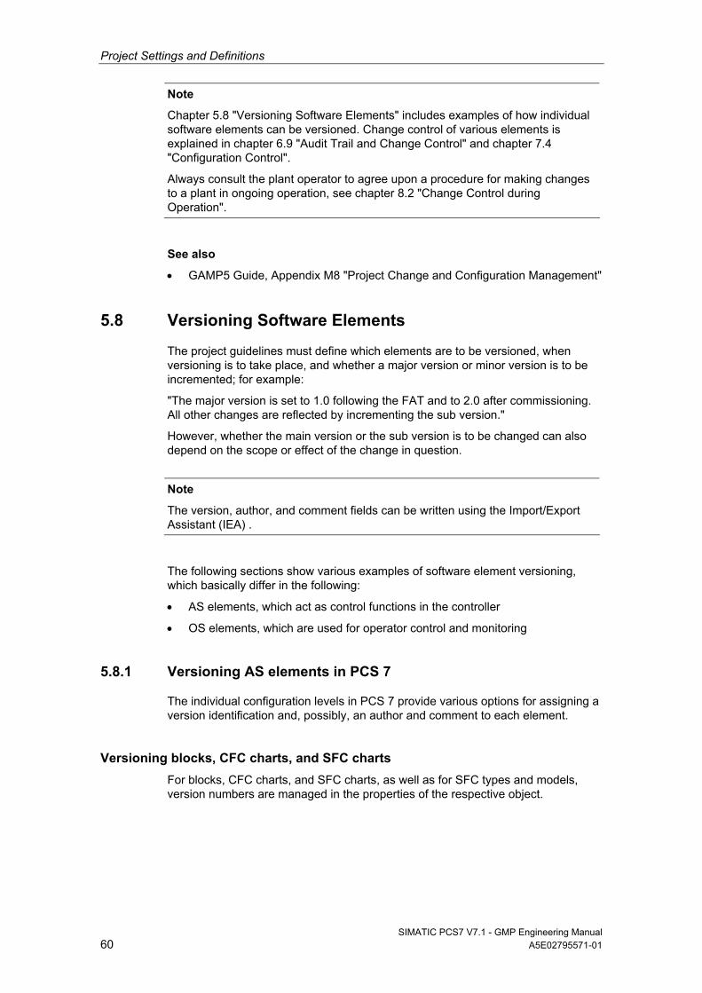
Project Settings and Definitions
SIMATIC PCS7 V7.1 - GMP Engineering Manual 60 A5E02795571-01
Note
Chapter 5.8 "Versioning Software Elements" includes examples of how individual software elements can be versioned. Change control of various elements is explained in chapter 6.9 "Audit Trail and Change Control" and chapter 7.4 "Configuration Control".
Always consult the plant operator to agree upon a procedure for making changes to a plant in ongoing operation, see chapter 8.2 "Change Control during Operation".
See also
GAMP5 Guide, Appendix M8 "Project Change and Configuration Management"
5.8 Versioning Software Elements
The project guidelines must define which elements are to be versioned, when versioning is to take place, and whether a major version or minor version is to be incremented; for example:
"The major version is set to 1.0 following the FAT and to 2.0 after commissioning. All other changes are reflected by incrementing the sub version."
However, whether the main version or the sub version is to be changed can also depend on the scope or effect of the change in question.
Note
The version, author, and comment fields can be written using the Import/Export Assistant (IEA) .
The following sections show various examples of software element versioning, which basically differ in the following:
AS elements, which act as control functions in the controller
OS elements, which are used for operator control and monitoring
5.8.1 Versioning AS elements in PCS 7
The individual configuration levels in PCS 7 provide various options for assigning a version identification and, possibly, an author and comment to each element.
Versioning blocks, CFC charts, and SFC charts
For blocks, CFC charts, and SFC charts, as well as for SFC types and models, version numbers are managed in the properties of the respective object.
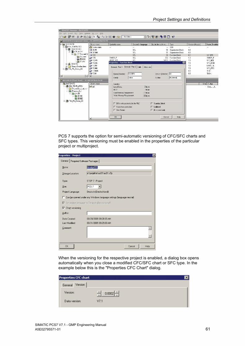
Project Settings and Definitions
SIMATIC PCS7 V7.1 - GMP Engineering Manual A5E02795571-01 61
PCS 7 supports the option for semi-automatic versioning of CFC/SFC charts and SFC types. This versioning must be enabled in the properties of the particular project or multiproject.
When the versioning for the respective project is enabled, a dialog box opens automatically when you close a modified CFC/SFC chart or SFC type. In the example below this is the "Properties CFC Chart" dialog.
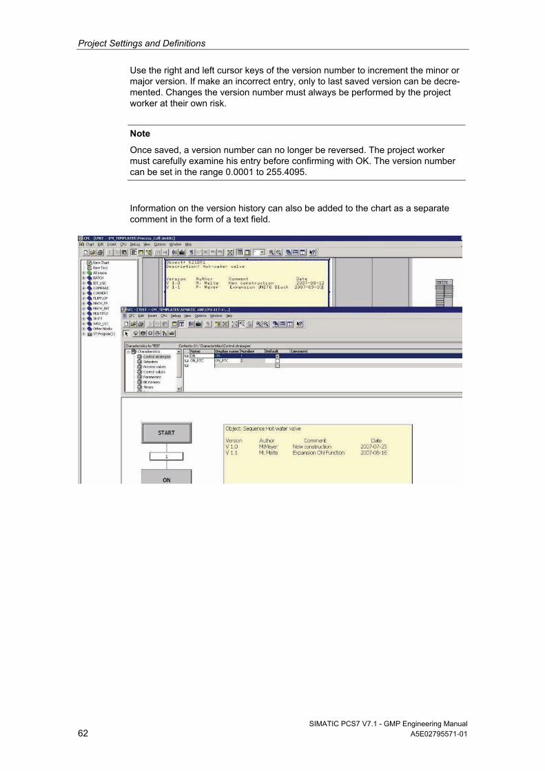
Project Settings and Definitions
SIMATIC PCS7 V7.1 - GMP Engineering Manual 62 A5E02795571-01
Use the right and left cursor keys of the version number to increment the minor or major version. If make an incorrect entry, only to last saved version can be decre-mented. Changes the version number must always be performed by the project worker at their own risk.
Note
Once saved, a version number can no longer be reversed. The project worker must carefully examine his entry before confirming with OK. The version number can be set in the range 0.0001 to 255.4095.
Information on the version history can also be added to the chart as a separate comment in the form of a text field.
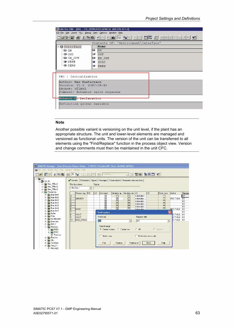
Project Settings and Definitions
SIMATIC PCS7 V7.1 - GMP Engineering Manual A5E02795571-01 63
Note
Another possible variant is versioning on the unit level, if the plant has an appropriate structure. The unit and lower-level elements are managed and versioned as functional units. The version of the unit can be transferred to all elements using the "Find/Replace" function in the process object view. Version and change comments must then be maintained in the unit CFC.
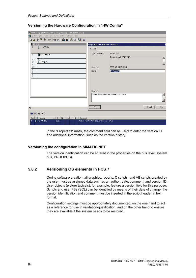
Project Settings and Definitions
SIMATIC PCS7 V7.1 - GMP Engineering Manual 64 A5E02795571-01
Versioning the Hardware Configuration in "HW Config"
In the "Properties" mask, the comment field can be used to enter the version ID and additional information, such as the version history.
Versioning the configuration in SIMATIC NET
The version identification can be entered in the properties on the bus level (system bus, PROFIBUS).
5.8.2 Versioning OS elements in PCS 7
During software creation, all graphics, reports, C scripts, and VB scripts created by the user must be assigned data such as an author, date, comment, and version ID. User objects (picture typicals), for example, feature a version field for this purpose. Scripts and user FBs (SCL) can be identified by means of their date of change; the version identification and comment must be inserted in the script header in text format.
Configuration settings must be appropriately documented, on the one hand to act as a reference for use in validation/qualification, and on the other hand to ensure they are available if the system needs to be restored.
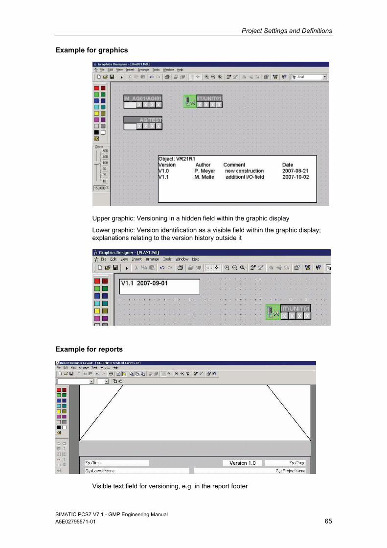
Project Settings and Definitions
SIMATIC PCS7 V7.1 - GMP Engineering Manual A5E02795571-01 65
Example for graphics
Upper graphic: Versioning in a hidden field within the graphic display
Lower graphic: Version identification as a visible field within the graphic display; explanations relating to the version history outside it
Example for reports
Visible text field for versioning, e.g. in the report footer
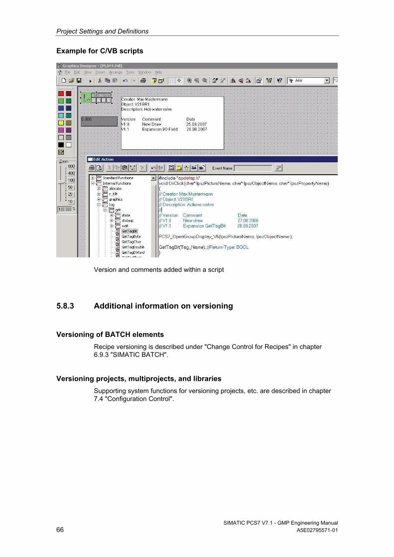
Project Settings and Definitions
SIMATIC PCS7 V7.1 - GMP Engineering Manual 66 A5E02795571-01
Example for C/VB scripts
Version and comments added within a script
5.8.3 Additional information on versioning
Versioning of BATCH elements
Recipe versioning is described under "Change Control for Recipes" in chapter 6.9.3 "SIMATIC BATCH".
Versioning projects, multiprojects, and libraries
Supporting system functions for versioning projects, etc. are described in chapter 7.4 "Configuration Control".
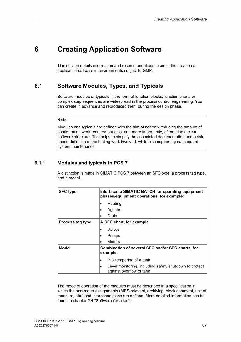
Creating Application Software
SIMATIC PCS7 V7.1 - GMP Engineering Manual A5E02795571-01 67
6 Creating Application Software
This section details information and recommendations to aid in the creation of application software in environments subject to GMP.
6.1 Software Modules, Types, and Typicals
Software modules or typicals in the form of function blocks, function charts or complex step sequences are widespread in the process control engineering. You can create in advance and reproduced them during the design phase.
Note
Modules and typicals are defined with the aim of not only reducing the amount of configuration work required but also, and more importantly, of creating a clear software structure. This helps to simplify the associated documentation and a risk-based definition of the testing work involved, while also supporting subsequent system maintenance.
6.1.1 Modules and typicals in PCS 7
A distinction is made in SIMATIC PCS 7 between an SFC type, a process tag type, and a model.
SFC type Interface to SIMATIC BATCH for operating equipment phases/equipment operations, for example:
Heating
Agitate
Drain
Process tag type A CFC chart, for example
Valves
Pumps
Motors
Model Combination of several CFC and/or SFC charts, for example:
PID tempering of a tank
Level monitoring, including safety shutdown to protect against overflow of tank
The mode of operation of the modules must be described in a specification in which the parameter assignments (MES-relevant, archiving, block comment, unit of measure, etc.) and interconnections are defined. More detailed information can be found in chapter 2.4 "Software Creation".
Creating Application Software
SIMATIC PCS7 V7.1 - GMP Engineering Manual 68 A5E02795571-01
Notes
Modules are named in accordance with the Functional Specification and the Design Specification.
The modules/typicals must be verified and approved by means of a module test before they are duplicated.
An up-to-date record of the software modules used must be kept for each AS, in the form of a document containing software version details.
SFC type
The SIMATIC PCS 7 type/instance concept enables types of sequential controls to be created. The "SFC type" allows sequential controls to be defined, including an interface in the form of a CFC block. The sequence logic of the SFC type is based on the interface I/Os of the SFC type, i.e. in contrast to an SFC chart, an SFC type cannot access just any process signals.
More detailed information on this topic can be found in the manual "SFC for SIMATIC S7".
The SFC type is not executable on its own. An SFC type, just like a function block type, must be placed in a CFC chart before it receives an executable object, in this case an SFC instance. The SFC type and SFC instances are compiled when the program is compiled. To execute an SFC instance, both the SFC type and the SFC instance are downloaded to the automation system.
Process tag type / model
With SIMATIC PCS 7, a process tag type/model consisting of one or more CFC and/or SFC charts can be created for subcomponents of the same type. Creating process tag types or models for similar plant units saves on work required for engineering and testing. Once a process tag type or model has been tested, it can quickly be duplicated as often as required in the multiproject in the form of replicas. For each replica, the plant hierarchy, CFC name, messages, I/Os for parameters or signals, and various module properties can be adapted.
Each block instance can also be assigned a picture icon, which can then be automatically inserted, along with its tag interface, into the flow chart defined in the SIMATIC Manager by deriving it from the screen hierarchy during OS compilation. This saves work and ensures that the picture icon is connected to the correct block instance. Models can contain pictures and reports.
Note
See chapter 6.1.3 "Automatic generation of block icons" for information on using block icons. These faceplates should be tested together with the associated software module as a process tag type and approved by the customer before they are duplicated.
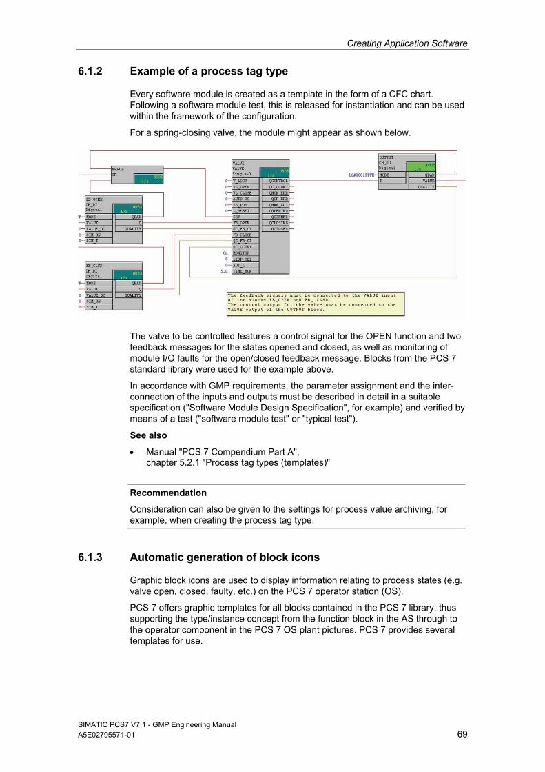
Creating Application Software
SIMATIC PCS7 V7.1 - GMP Engineering Manual A5E02795571-01 69
6.1.2 Example of a process tag type
Every software module is created as a template in the form of a CFC chart. Following a software module test, this is released for instantiation and can be used within the framework of the configuration.
For a spring-closing valve, the module might appear as shown below.
The valve to be controlled features a control signal for the OPEN function and two feedback messages for the states opened and closed, as well as monitoring of module I/O faults for the open/closed feedback message. Blocks from the PCS 7 standard library were used for the example above.
In accordance with GMP requirements, the parameter assignment and the inter-connection of the inputs and outputs must be described in detail in a suitable specification ("Software Module Design Specification", for example) and verified by means of a test ("software module test" or "typical test").
See also
Manual "PCS 7 Compendium Part A", chapter 5.2.1 "Process tag types (templates)"
Recommendation
Consideration can also be given to the settings for process value archiving, for example, when creating the process tag type.
6.1.3 Automatic generation of block icons
Graphic block icons are used to display information relating to process states (e.g. valve open, closed, faulty, etc.) on the PCS 7 operator station (OS).
PCS 7 offers graphic templates for all blocks contained in the PCS 7 library, thus supporting the type/instance concept from the function block in the AS through to the operator component in the PCS 7 OS plant pictures. PCS 7 provides several templates for use.
Creating Application Software
SIMATIC PCS7 V7.1 - GMP Engineering Manual 70 A5E02795571-01
Note
Generating block icons automatically reduces the risk of an error occurring.
See also
PCS 7 on Tour – Basic, chapter 10 / 5.1 "Adapted block icons and faceplates"
If the Create/Update Block Icons function is executed, the block icons are derived from the plant hierarchy of the project by means of their names and priorities, copied from the templates, and automatically linked to the tag interface of the relevant operator panel.
Priority Screen name Remark 1. @PCS7Typicals*.pdl Starting with the picture which comes last
alphabetically 2. @PCS7Typicals.pdl 3. @@PCS7Typicals.pdl Contained in the standard
The @@PCS7Typicals.pdl template
The "@@PCS7Typicals.pdl" picture is included in every PCS 7 OS project by default. It contains the standard block icons.
Note
The "@@PCS7Typicals.pdl" original file must not be changed under any circumstances. Any changes to the original file will be overwritten when an update or upgrade is performed.
Separate templates should be created for customer-specific block, "@PCS7Typicals*.pdl".
See also
Product Support http://support.automation.siemens.com/DE/view/de/26697820
Product Support http://support.automation.siemens.com/DE/view/de/19688107
Project-specific template
A project-specific template, "@PCS7Typicals*.pdl", can be created by copying template "@@PCS7Typicals.pdl". Customer-specific changes can then be made to the "new" template.
The @Template.pdl template
The "@Template.pdl" template is primarily used when block icons are inserted into pictures manually. These block icons are not connected to the plant hierarchy and are not, therefore, created or updated by the system.
As a result, it can be helpful to use the template file. On the one hand you are not then linked to the plant hierarchy, and on the other hand you can use a wizard to export picture objects from one or all flow charts to a configuration file, modify block icons and their connections, and finally import the picture objects again. The configuration file can be edited using tools such as Excel.
Creating Application Software
Note
The "@Template.pdl" file is maintained by the PCS 7 system and is overwritten when an update or upgrade is performed. It is therefore advisable to back up the "@Template.pdl" file on a regular basis.
Other Template Pictures
@@ConfigTypicals.pdl Used to create/update lifebeat monitoring.
@@MaintenanceTypicals.pdl Used to create/update diagnostic pictures.
@pcs7elements.pdl The template contains a collection of predefined objects for creating faceplates.
@PCS7Typicals_Batch.pdl Used to create/update block icons for SIMATIC BATCH.
@PCS7Typicalsrc.pdl Used to create/update block icons for SIMATIC Route Control.
This list is not exhaustive.
Central changeability of picture objects
In the type definition, SIMATIC PCS 7 allows objects to be changed centrally; in other words, subsequent changes to picture objects are made in the template pictures.
Note
The central changeability of picture objects does not mean that changes are automatically passed on/down to the instances. As a result, the "Export Picture Objects" function must be executed via the dynamic wizard before the changes are passed on; this ensures that all objects will be located at their original positions after "Import Picture Objects" is performed.
6.2 Bulk Engineering with the IEA
The Import/Export Assistant (IEA) is used for two tasks.
Duplication with the IEA
The Import/Export Assistant is used to duplicate process tag types or models. This is achieved by defining project-dependent typicals on the basis of standard libraries; these typicals can then be copied as often as required by using the Import/Export Assistant to perform instantiation.
SIMATIC PCS7 V7.1 - GMP Engineering Manual A5E02795571-01 71
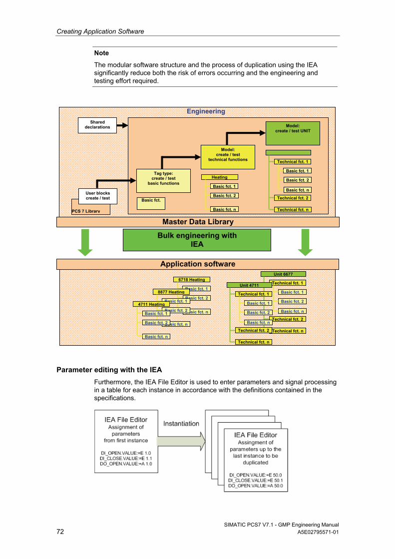
Creating Application Software
SIMATIC PCS7 V7.1 - GMP Engineering Manual 72 A5E02795571-01
Note
The modular software structure and the process of duplication using the IEA significantly reduce both the risk of errors occurring and the engineering and testing effort required.
Parameter editing with the IEA
Furthermore, the IEA File Editor is used to enter parameters and signal processing in a table for each instance in accordance with the definitions contained in the specifications.
Technical fct. 1
Basic fct. 1
Basic fct. 2
Basic fct. n
Unit 6677
Technical fct. 2
Technical fct. n
6718 Heating
Basic fct. 1
Basic fct. 2
Basic fct. n
PCS 7 Library
User blocks create / test
Shared declarations
Tag type: create / test
basic functions
Engineering
Model:create / test
technical functions
Model: create / test UNIT
Basic fct.
Heating
Basic fct. 1
Basic fct. 2
Basic fct. n
Technical fct. 1
Basic fct. 1
Basic fct. 2
Basic fct. n
Technical fct. 2
Technical fct. n
Master Data Library
Bulk engineering with IEA
8877 Heating
Basic fct. 1
Basic fct. 2
Basic fct. n
4711 Heating
Basic fct. 1
Basic fct. 2
Basic fct. n
Technical fct. 1
Basic fct. 1
Basic fct. 2
Basic fct. n
Unit 4711
Technical fct. 2
Technical fct. n
Application software
Creating Application Software
SIMATIC PCS7 V7.1 - GMP Engineering Manual A5E02795571-01 73
Note
The Import-Export Assistant is managed as a separate add-on package in SIMATIC PCS 7. It is included on the PCS 7 Toolset DVD and installed as part of the general setup, although it does require a separate license.
See also
Manual "PCS 7 Engineering System (V7.1)", chapter 8.11.7 "Creating process tags from process tag types (multiproject)"
6.3 Creating Process Diagrams
See chapter 6.1.3 "Automatic generation of block icons" to learn how to use templates as a library for graphic typicals.
Process diagrams must be created in accordance with the definitions contained in the specifications (e.g. URS, FS, and P&I).
Block icons should be assigned using the "automatic generation of block icons" function, i.e. one block icon is assigned to each instance-specific module (valve, pump, closed-loop controller, etc.) in the process picture using the IEA file. The picture and the block charts must be configured in the same plant hierarchy folder, or in plant hierarchy folders with the same name, in order for block icons to be generated.
After the graphics are created, they should be submitted to the customer in the form of screen shots for approval.
See also
Manual "PCS 7 Compendium Part A", chapter 7.2 "Visualization interface"
6.4 User-Specific Blocks and Scripts
User-specific blocks (FB, FC) and scripts (C, VB) are programs written and created by the user, which are assigned to GAMP software category 5, see chapter 7.3.1 "Software categorization according to GAMP Guide" for more on this. This type of software was developed to meet customer-specific demands not covered by existing functions and libraries.
Note
The creation of category 5 software should be avoided if possible because it significantly increases the testing and validation work required.
The procedure for creating GAMP category 5 software is as follows: 1. Creation of a functional description for the software 2. Specification of the function blocks used 3. Specification of the inputs and outputs used 4. Specification of the operator control and monitoring capability 5. Creation of software following specifications and programming guidelines 6. Testing of the structure for compliance with programming guidelines 7. Testing of the function for compliance with the functional description 8. Approval prior to use and/or duplication
Creating Application Software
SIMATIC PCS7 V7.1 - GMP Engineering Manual 74 A5E02795571-01
When creating user-specific blocks and scripts, the rules for the creation of software elements should be defined in instructions specific to the pro-ject/department (SOP coding standards, PCS 7 style guide, etc.).
See also
Manual "PCS 7 V7.0 Programming Instructions for Blocks"
Manual "PCS 7 Compendium Part A", chapter 5.1.2 "Creating user-defined technological blocks"
6.5 Interfaces to PCS 7
6.5.1 PCS 7 OS Web Option
This option enables PCS 7 system processes to be controlled and monitored via an Internet/Intranet connection. One PCS 7 OS Web server and at least one PCS 7 Web client is required.
Within a PCS 7 OS multiple station system the PCS 7 OS Web server is installed as an OS client with PCS 7 OS Web server functionality. It should not be used as an operator station (OS client). This can be ensured by deactivating graphics runtime.
The WebViewer is installed automatically when the Web client is installed. For remote access, it is advisable to use this in preference to the Internet Explorer since the WebViewer can be custom configured.
The Web server itself should be certified so that access to Web server functions is secure, authenticated, and encrypted (keyword: https access).
All pictures and required scripts are stored on the OS Web server so that they can be displayed and run on the Web client. All pictures and scripts must be published The "Web View Publisher" is used for this.
See also
Manual "PCS 7 OS Web Option", the topic of using scripts
Manual "PCS 7 V7.0 Programming Instructions for Blocks", chapter 2.1.10 "WebClient (differences compared to WinCC)"
Manual "PCS 7 Compendium Part A", chapter 7.2 "Visualization interface"
Note
If scripts are used, preference should be given to event-controlled script editing wherever possible, as it saves on resources. By contrast, cyclic scripts should only be used on a specific basis, if necessary.
SIMATIC Logon must be installed on the Web server, thus integrating the Web client into the SIMATIC Logon functions. As a result, access to the Web client is password-protected. User rights are assigned in OS user management. They correspond to those of standard clients, the only additional requirement is that the Intranet/Internet access option must be enabled.
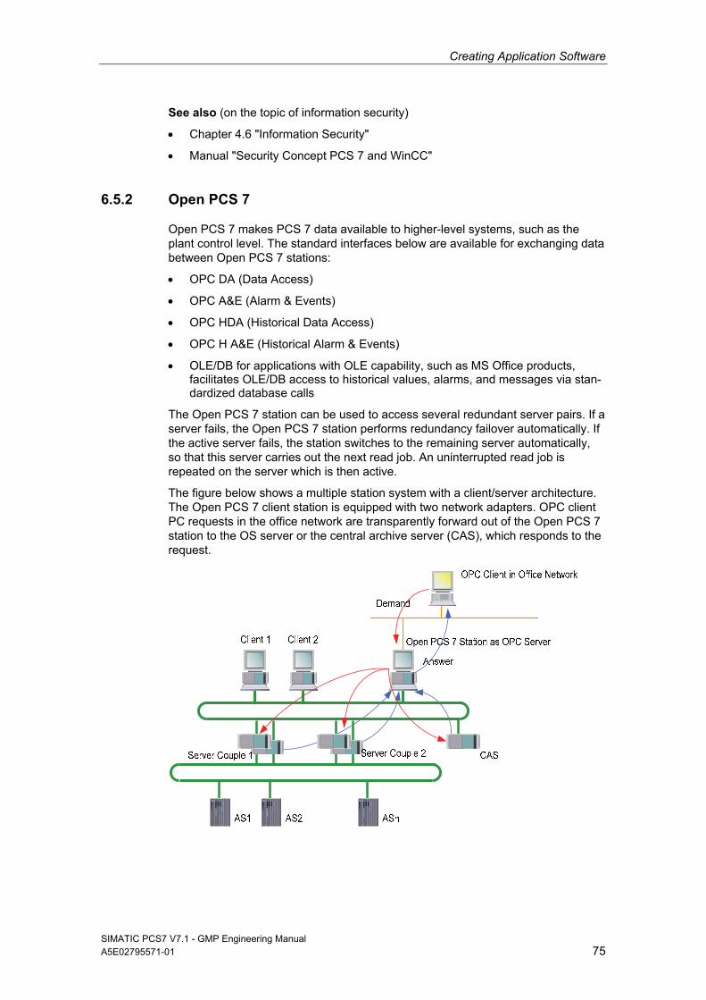
Creating Application Software
SIMATIC PCS7 V7.1 - GMP Engineering Manual A5E02795571-01 75
See also (on the topic of information security)
Chapter 4.6 "Information Security"
Manual "Security Concept PCS 7 and WinCC"
6.5.2 Open PCS 7
Open PCS 7 makes PCS 7 data available to higher-level systems, such as the plant control level. The standard interfaces below are available for exchanging data between Open PCS 7 stations:
OPC DA (Data Access)
OPC A&E (Alarm & Events)
OPC HDA (Historical Data Access)
OPC H A&E (Historical Alarm & Events)
OLE/DB for applications with OLE capability, such as MS Office products, facilitates OLE/DB access to historical values, alarms, and messages via stan-dardized database calls
The Open PCS 7 station can be used to access several redundant server pairs. If a server fails, the Open PCS 7 station performs redundancy failover automatically. If the active server fails, the station switches to the remaining server automatically, so that this server carries out the next read job. An uninterrupted read job is repeated on the server which is then active.
The figure below shows a multiple station system with a client/server architecture. The Open PCS 7 client station is equipped with two network adapters. OPC client PC requests in the office network are transparently forward out of the Open PCS 7 station to the OS server or the central archive server (CAS), which responds to the request.
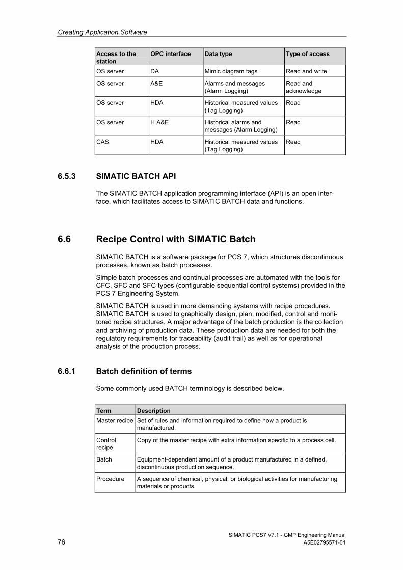
Creating Application Software
SIMATIC PCS7 V7.1 - GMP Engineering Manual 76 A5E02795571-01
Access to the station
OPC interface Data type Type of access
OS server DA Mimic diagram tags Read and write
OS server A&E Alarms and messages (Alarm Logging)
Read and acknowledge
OS server HDA Historical measured values (Tag Logging)
Read
OS server H A&E Historical alarms and messages (Alarm Logging)
Read
CAS HDA Historical measured values (Tag Logging)
Read
6.5.3 SIMATIC BATCH API
The SIMATIC BATCH application programming interface (API) is an open inter-face, which facilitates access to SIMATIC BATCH data and functions.
6.6 Recipe Control with SIMATIC Batch
SIMATIC BATCH is a software package for PCS 7, which structures discontinuous processes, known as batch processes.
Simple batch processes and continual processes are automated with the tools for CFC, SFC and SFC types (configurable sequential control systems) provided in the PCS 7 Engineering System.
SIMATIC BATCH is used in more demanding systems with recipe procedures. SIMATIC BATCH is used to graphically design, plan, modified, control and moni-tored recipe structures. A major advantage of the batch production is the collection and archiving of production data. These production data are needed for both the regulatory requirements for traceability (audit trail) as well as for operational analysis of the production process.
6.6.1 Batch definition of terms
Some commonly used BATCH terminology is described below.
Term Description
Master recipe Set of rules and information required to define how a product is manufactured.
Control recipe
Copy of the master recipe with extra information specific to a process cell.
Batch Equipment-dependent amount of a product manufactured in a defined, discontinuous production sequence.
Procedure A sequence of chemical, physical, or biological activities for manufacturing materials or products.
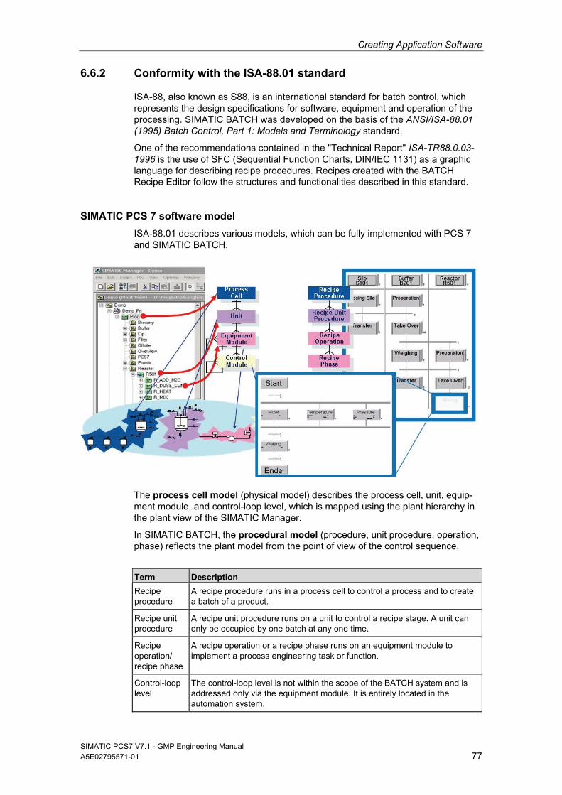
Creating Application Software
SIMATIC PCS7 V7.1 - GMP Engineering Manual A5E02795571-01 77
6.6.2 Conformity with the ISA-88.01 standard
ISA-88, also known as S88, is an international standard for batch control, which represents the design specifications for software, equipment and operation of the processing. SIMATIC BATCH was developed on the basis of the ANSI/ISA-88.01 (1995) Batch Control, Part 1: Models and Terminology standard.
One of the recommendations contained in the "Technical Report" ISA-TR88.0.03-1996 is the use of SFC (Sequential Function Charts, DIN/IEC 1131) as a graphic language for describing recipe procedures. Recipes created with the BATCH Recipe Editor follow the structures and functionalities described in this standard.
SIMATIC PCS 7 software model
ISA-88.01 describes various models, which can be fully implemented with PCS 7 and SIMATIC BATCH.
The process cell model (physical model) describes the process cell, unit, equip-ment module, and control-loop level, which is mapped using the plant hierarchy in the plant view of the SIMATIC Manager.
In SIMATIC BATCH, the procedural model (procedure, unit procedure, operation, phase) reflects the plant model from the point of view of the control sequence.
Term Description
Recipe procedure
A recipe procedure runs in a process cell to control a process and to create a batch of a product.
Recipe unit procedure
A recipe unit procedure runs on a unit to control a recipe stage. A unit can only be occupied by one batch at any one time.
Recipe operation/ recipe phase
A recipe operation or a recipe phase runs on an equipment module to implement a process engineering task or function.
Control-loop level
The control-loop level is not within the scope of the BATCH system and is addressed only via the equipment module. It is entirely located in the automation system.
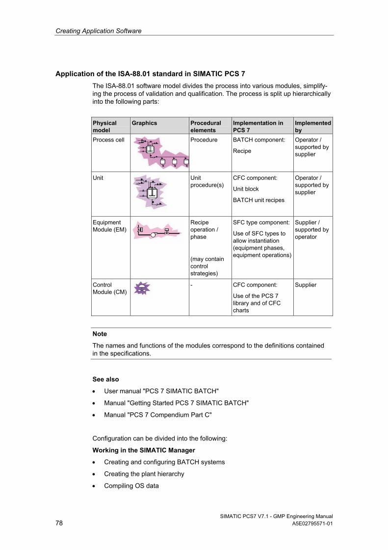
Creating Application Software
SIMATIC PCS7 V7.1 - GMP Engineering Manual 78 A5E02795571-01
Application of the ISA-88.01 standard in SIMATIC PCS 7
The ISA-88.01 software model divides the process into various modules, simplify-ing the process of validation and qualification. The process is split up hierarchically into the following parts:
Physical model
Graphics Procedural elements
Implementation in PCS 7
Implemented by
Process cell Procedure
BATCH component:
Recipe
Operator / supported by supplier
Unit
Unit procedure(s)
CFC component:
Unit block
BATCH unit recipes
Operator / supported by supplier
Equipment Module (EM)
Recipe operation / phase
(may contain control strategies)
SFC type component:
Use of SFC types to allow instantiation (equipment phases, equipment operations)
Supplier / supported by operator
Control Module (CM)
- CFC component:
Use of the PCS 7 library and of CFC charts
Supplier
Note
The names and functions of the modules correspond to the definitions contained in the specifications.
See also
User manual "PCS 7 SIMATIC BATCH"
Manual "Getting Started PCS 7 SIMATIC BATCH"
Manual "PCS 7 Compendium Part C"
Configuration can be divided into the following:
Working in the SIMATIC Manager
Creating and configuring BATCH systems
Creating the plant hierarchy
Compiling OS data
Creating Application Software
SIMATIC PCS7 V7.1 - GMP Engineering Manual A5E02795571-01 79
Generating BATCH types (SFC type)
Propagating BATCH types
Compiling instances
Transferring data to OS
Loading process cell data
Working in the BATCH Control Center (BCC) and Recipe Editor (RP)
Reading batch data
Creating master recipes
Creating the recipe structure
Releasing master recipes for production
Creating an order
Releasing a batch
Creating ROP libraries (typicals)
Exporting/importing recipes, parameter sets, etc.
6.6.3 Important settings in SIMATIC BATCH
Various project settings can be defined in SIMATIC BATCH. These settings are described in detail in the relevant system documentation.
Online structure changes for recipe structures
SIMATIC BATCH allows you to change recipe structures in both hierarchical recipes and flat recipes. This applies to control recipes that have the status "released", "planned" or "started". However, such online structural changes are intended only to provide additional functionality for master recipes during testing. They serve to simplify the optimization of recipes. Online structural changes cannot be performed during production (master recipe released for production).
Settings for performing online structure changes
The master recipe has the status "Release for testing".
The user must have the "structural changes" permission.
The check mark must be set for "All online structure modifications" in the project settings, as shown below.
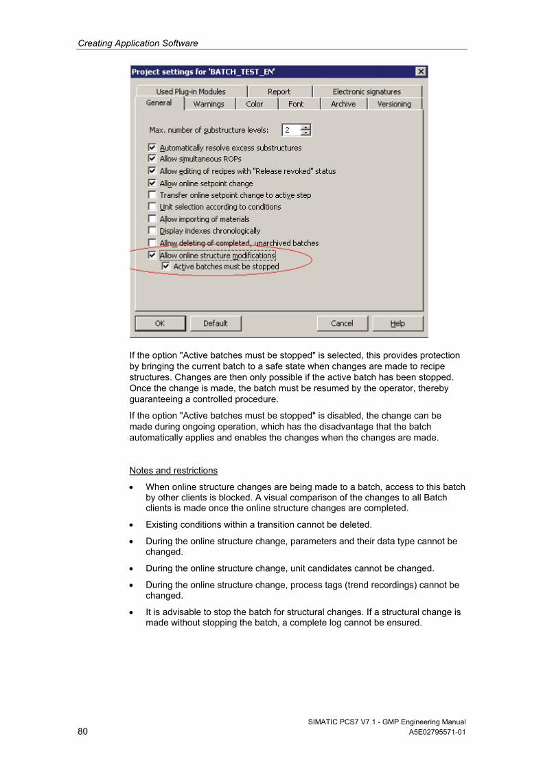
Creating Application Software
SIMATIC PCS7 V7.1 - GMP Engineering Manual 80 A5E02795571-01
If the option "Active batches must be stopped" is selected, this provides protection by bringing the current batch to a safe state when changes are made to recipe structures. Changes are then only possible if the active batch has been stopped. Once the change is made, the batch must be resumed by the operator, thereby guaranteeing a controlled procedure.
If the option "Active batches must be stopped" is disabled, the change can be made during ongoing operation, which has the disadvantage that the batch automatically applies and enables the changes when the changes are made.
Notes and restrictions
When online structure changes are being made to a batch, access to this batch by other clients is blocked. A visual comparison of the changes to all Batch clients is made once the online structure changes are completed.
Existing conditions within a transition cannot be deleted.
During the online structure change, parameters and their data type cannot be changed.
During the online structure change, unit candidates cannot be changed.
During the online structure change, process tags (trend recordings) cannot be changed.
It is advisable to stop the batch for structural changes. If a structural change is made without stopping the batch, a complete log cannot be ensured.
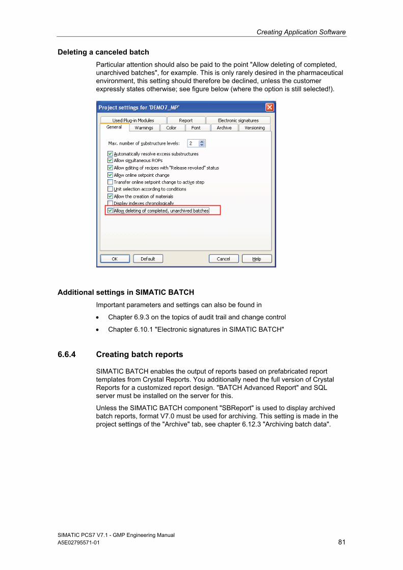
Creating Application Software
SIMATIC PCS7 V7.1 - GMP Engineering Manual A5E02795571-01 81
Deleting a canceled batch
Particular attention should also be paid to the point "Allow deleting of completed, unarchived batches", for example. This is only rarely desired in the pharmaceutical environment, this setting should therefore be declined, unless the customer expressly states otherwise; see figure below (where the option is still selected!).
Additional settings in SIMATIC BATCH
Important parameters and settings can also be found in
Chapter 6.9.3 on the topics of audit trail and change control
Chapter 6.10.1 "Electronic signatures in SIMATIC BATCH"
6.6.4 Creating batch reports
SIMATIC BATCH enables the output of reports based on prefabricated report templates from Crystal Reports. You additionally need the full version of Crystal Reports for a customized report design. "BATCH Advanced Report" and SQL server must be installed on the server for this.
Unless the SIMATIC BATCH component "SBReport" is used to display archived batch reports, format V7.0 must be used for archiving. This setting is made in the project settings of the "Archive" tab, see chapter 6.12.3 "Archiving batch data".
Creating Application Software
SIMATIC PCS7 V7.1 - GMP Engineering Manual 82 A5E02795571-01
6.7 SIMATIC Route Control
SIMATIC Route Control is the secure, automated transport of materials. Typical application examples include:
Transport of solids and liquids
Buffer applications and provision of buffers for production
Bio-reactors, such as cell culture plants with upstream and downstream
CIP and SIP procedures with various flushing paths
The use of SIMATIC Route Control becomes economical with as few as 5 parallel material transports. The main benefit of this is in engineering. The engineering is similar to the configuration of SIMATIC BATCH. With the SIMATIC Route Control Center, routes and partial routes are easily assembled. The easy-to-understand visualization in SIMATIC Route Control Center makes it easy to allocate production and cleaning paths, whereby the amount of validation and qualification is signifi-cantly reduced. Furthermore, the material tracking is ensured by SIMATIC Route Control (Route Control Log).
A Route Control server is needed in order to use SIMATIC Route Control. Route Control servers can have a redundant configuration. SIMATIC Route Control is configured on the SIMATIC PCS 7 engineering station.
6.8 Alarm Management
An alarm system must be able to perform the following basic functions:
Warn the operator in the event of problems in the plant
Provide information about the characteristics of the problem
Guide the operator to the most significant problem
Support the operator in evaluating multiple pending problems
6.8.1 Specification
The specification of an alarm system includes the following:
Definition of formats for alarm line and alarm page
Message classes, colors, and priorities
Acknowledgment concept (e.g. single acknowledgment)
Event texts, e.g. "too high" for a high alarm
Process-dependent alarm suppression, e.g. suppression of flow monitoring if a pump is switched off
These points must be defined if they deviate from standard specifications.
The default standards for displaying message classes, colors, and priorities must be retained if possible and should only be changed upon customer request.
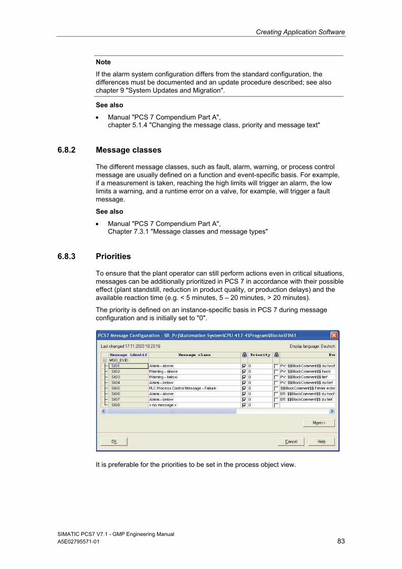
Creating Application Software
SIMATIC PCS7 V7.1 - GMP Engineering Manual A5E02795571-01 83
Note
If the alarm system configuration differs from the standard configuration, the differences must be documented and an update procedure described; see also chapter 9 "System Updates and Migration".
See also
Manual "PCS 7 Compendium Part A", chapter 5.1.4 "Changing the message class, priority and message text"
6.8.2 Message classes
The different message classes, such as fault, alarm, warning, or process control message are usually defined on a function and event-specific basis. For example, if a measurement is taken, reaching the high limits will trigger an alarm, the low limits a warning, and a runtime error on a valve, for example, will trigger a fault message.
See also
Manual "PCS 7 Compendium Part A", Chapter 7.3.1 "Message classes and message types"
6.8.3 Priorities
To ensure that the plant operator can still perform actions even in critical situations, messages can be additionally prioritized in PCS 7 in accordance with their possible effect (plant standstill, reduction in product quality, or production delays) and the available reaction time (e.g. < 5 minutes, 5 – 20 minutes, > 20 minutes).
The priority is defined on an instance-specific basis in PCS 7 during message configuration and is initially set to "0".
It is preferable for the priorities to be set in the process object view.
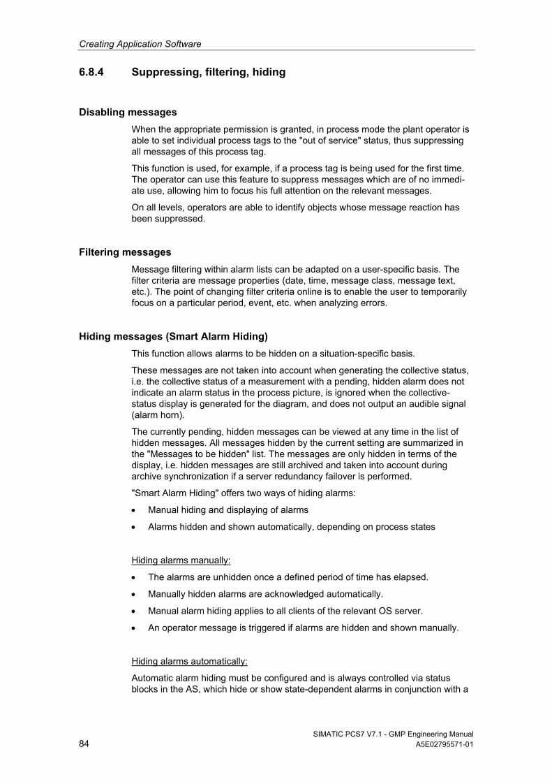
Creating Application Software
SIMATIC PCS7 V7.1 - GMP Engineering Manual 84 A5E02795571-01
6.8.4 Suppressing, filtering, hiding
Disabling messages
When the appropriate permission is granted, in process mode the plant operator is able to set individual process tags to the "out of service" status, thus suppressing all messages of this process tag.
This function is used, for example, if a process tag is being used for the first time. The operator can use this feature to suppress messages which are of no immedi-ate use, allowing him to focus his full attention on the relevant messages.
On all levels, operators are able to identify objects whose message reaction has been suppressed.
Filtering messages
Message filtering within alarm lists can be adapted on a user-specific basis. The filter criteria are message properties (date, time, message class, message text, etc.). The point of changing filter criteria online is to enable the user to temporarily focus on a particular period, event, etc. when analyzing errors.
Hiding messages (Smart Alarm Hiding)
This function allows alarms to be hidden on a situation-specific basis.
These messages are not taken into account when generating the collective status, i.e. the collective status of a measurement with a pending, hidden alarm does not indicate an alarm status in the process picture, is ignored when the collective-status display is generated for the diagram, and does not output an audible signal (alarm horn).
The currently pending, hidden messages can be viewed at any time in the list of hidden messages. All messages hidden by the current setting are summarized in the "Messages to be hidden" list. The messages are only hidden in terms of the display, i.e. hidden messages are still archived and taken into account during archive synchronization if a server redundancy failover is performed.
"Smart Alarm Hiding" offers two ways of hiding alarms:
Manual hiding and displaying of alarms
Alarms hidden and shown automatically, depending on process states
Hiding alarms manually:
The alarms are unhidden once a defined period of time has elapsed.
Manually hidden alarms are acknowledged automatically.
Manual alarm hiding applies to all clients of the relevant OS server.
An operator message is triggered if alarms are hidden and shown manually.
Hiding alarms automatically:
Automatic alarm hiding must be configured and is always controlled via status blocks in the AS, which hide or show state-dependent alarms in conjunction with a
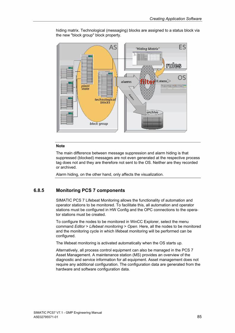
Creating Application Software
SIMATIC PCS7 V7.1 - GMP Engineering Manual A5E02795571-01 85
hiding matrix. Technological (messaging) blocks are assigned to a status block via the new "block group" block property.
Note
The main difference between message suppression and alarm hiding is that suppressed (blocked) messages are not even generated at the respective process tag does not and they are therefore not sent to the OS. Neither are they recorded or archived.
Alarm hiding, on the other hand, only affects the visualization.
6.8.5 Monitoring PCS 7 components
SIMATIC PCS 7 Lifebeat Monitoring allows the functionality of automation and operator stations to be monitored. To facilitate this, all automation and operator stations must be configured in HW Config and the OPC connections to the opera-tor stations must be created.
To configure the nodes to be monitored in WinCC Explorer, select the menu command Editor > Lifebeat monitoring > Open. Here, all the nodes to be monitored and the monitoring cycle in which lifebeat monitoring will be performed can be configured.
The lifebeat monitoring is activated automatically when the OS starts up.
Alternatively, all process control equipment can also be managed in the PCS 7 Asset Management. A maintenance station (MS) provides an overview of the diagnostic and service information for all equipment. Asset management does not require any additional configuration. The configuration data are generated from the hardware and software configuration data.
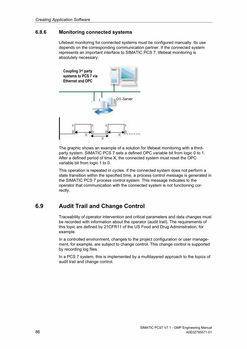
Creating Application Software
SIMATIC PCS7 V7.1 - GMP Engineering Manual 86 A5E02795571-01
6.8.6 Monitoring connected systems
Lifebeat monitoring for connected systems must be configured manually. Its use depends on the corresponding communication partner. If the connected system represents an important interface to SIMATIC PCS 7, lifebeat monitoring is absolutely necessary.
The graphic shows an example of a solution for lifebeat monitoring with a third-party system. SIMATIC PCS 7 sets a defined OPC variable bit from logic 0 to 1. After a defined period of time X, the connected system must reset the OPC variable bit from logic 1 to 0.
This operation is repeated in cycles. If the connected system does not perform a state transition within the specified time, a process control message is generated in the SIMATIC PCS 7 process control system. This message indicates to the operator that communication with the connected system is not functioning cor-rectly.
6.9 Audit Trail and Change Control
Traceability of operator intervention and critical parameters and data changes must be recorded with information about the operator (audit trail). The requirements of this topic are defined by 21CFR11 of the US Food and Drug Administration, for example.
In a controlled environment, changes to the project configuration or user manage-ment, for example, are subject to change control. This change control is supported by recording log files.
In a PCS 7 system, this is implemented by a multilayered approach to the topics of audit trail and change control.
Coupling 3rd party systems to PCS 7 via Ethernet and OPC
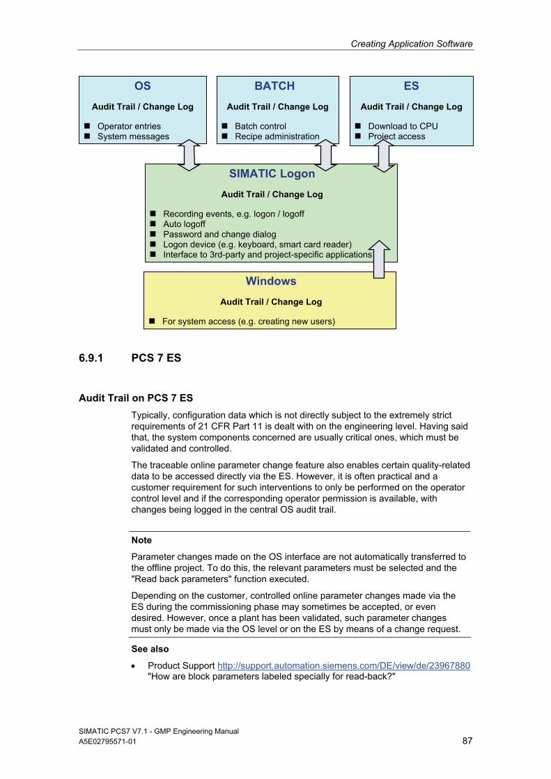
Creating Application Software
SIMATIC PCS7 V7.1 - GMP Engineering Manual A5E02795571-01 87
6.9.1 PCS 7 ES
Audit Trail on PCS 7 ES
Typically, configuration data which is not directly subject to the extremely strict requirements of 21 CFR Part 11 is dealt with on the engineering level. Having said that, the system components concerned are usually critical ones, which must be validated and controlled.
The traceable online parameter change feature also enables certain quality-related data to be accessed directly via the ES. However, it is often practical and a customer requirement for such interventions to only be performed on the operator control level and if the corresponding operator permission is available, with changes being logged in the central OS audit trail.
Note
Parameter changes made on the OS interface are not automatically transferred to the offline project. To do this, the relevant parameters must be selected and the "Read back parameters" function executed.
Depending on the customer, controlled online parameter changes made via the ES during the commissioning phase may sometimes be accepted, or even desired. However, once a plant has been validated, such parameter changes must only be made via the OS level or on the ES by means of a change request.
See also
Product Support http://support.automation.siemens.com/DE/view/de/23967880 "How are block parameters labeled specially for read-back?"
SIMATIC Logon
Audit Trail / Change Log
Recording events, e.g. logon / logoff Auto logoff Password and change dialog Logon device (e.g. keyboard, smart card reader) Interface to 3rd-party and project-specific applications
Windows
Audit Trail / Change Log
For system access (e.g. creating new users)
BATCH
Audit Trail / Change Log
Batch control Recipe administration
ES
Audit Trail / Change Log
Download to CPU Project access
OS
Audit Trail / Change Log
Operator entries System messages
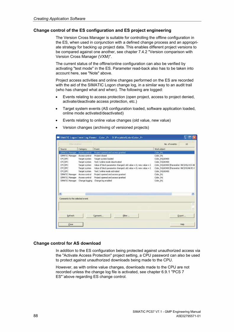
Creating Application Software
SIMATIC PCS7 V7.1 - GMP Engineering Manual 88 A5E02795571-01
Change control of the ES configuration and ES project engineering
The Version Cross Manager is suitable for controlling the offline configuration in the ES, when used in conjunction with a defined change process and an appropri-ate strategy for backing up project data. This enables different project versions to be compared against one another, see chapter 7.4.2 "Version comparison with Version Cross Manager (VXM)".
The current status of the offline/online configuration can also be verified by activating "test mode" in the ES. Parameter read-back also has to be taken into account here, see "Note" above.
Project access activities and online changes performed on the ES are recorded with the aid of the SIMATIC Logon change log, in a similar way to an audit trail (who has changed what and when). The following are logged:
Events relating to access protection (open project, access to project denied, activate/deactivate access protection, etc.)
Target system events (AS configuration loaded, software application loaded, online mode activated/deactivated)
Events relating to online value changes (old value, new value)
Version changes (archiving of versioned projects)
Change control for AS download
In addition to the ES configuration being protected against unauthorized access via the "Activate Access Protection" project setting, a CPU password can also be used to protect against unauthorized downloads being made to the CPU.
However, as with online value changes, downloads made to the CPU are not recorded unless the change log file is activated, see chapter 6.9.1 "PCS 7 ES"´above regarding ES change control.
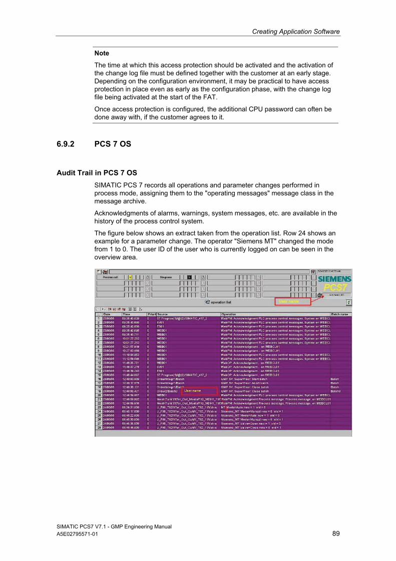
Creating Application Software
SIMATIC PCS7 V7.1 - GMP Engineering Manual A5E02795571-01 89
Note
The time at which this access protection should be activated and the activation of the change log file must be defined together with the customer at an early stage. Depending on the configuration environment, it may be practical to have access protection in place even as early as the configuration phase, with the change log file being activated at the start of the FAT.
Once access protection is configured, the additional CPU password can often be done away with, if the customer agrees to it.
6.9.2 PCS 7 OS
Audit Trail in PCS 7 OS
SIMATIC PCS 7 records all operations and parameter changes performed in process mode, assigning them to the "operating messages" message class in the message archive.
Acknowledgments of alarms, warnings, system messages, etc. are available in the history of the process control system.
The figure below shows an extract taken from the operation list. Row 24 shows an example for a parameter change. The operator "Siemens MT" changed the mode from 1 to 0. The user ID of the user who is currently logged on can be seen in the overview area.

Creating Application Software
SIMATIC PCS7 V7.1 - GMP Engineering Manual 90 A5E02795571-01
Notes
If parameter changes are made via input/output fields, message output must be configured separately.
Select the hard disk capacity so that the entire audit trail can be stored there until it is transferred to an external data medium.
Change control for the OS configuration and OS project engineering
The OS configuration, as well as the project engineering of OS elements (pictures, scripts, etc.), is versioned on the ES and archived, together with the overall project (SIMATIC Version Trail). Changes made to individual OS elements must be controlled in accordance with the applicable change procedure since initial release.
6.9.3 SIMATIC BATCH
Audit Trail in SIMATIC BATCH
Operator actions performed in SIMATIC BATCH are recorded in the same mes-sage archive as OS operator actions (see above).
A batch report containing information on the operations performed for each batch (who, when, what) is also created in SIMATIC BATCH.
Change control for recipes and batch objects
Changes made to recipe data and batch data (deleted batches, for example) are logged in the change log. The user, time, and action are entered in this log.
To ensure consistent version management, the following project settings must be made:
"System-aided versioning" option selected
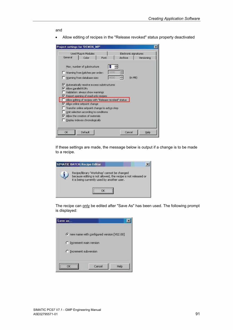
Creating Application Software
SIMATIC PCS7 V7.1 - GMP Engineering Manual A5E02795571-01 91
and
Allow editing of recipes in the "Release revoked" status property deactivated
If these settings are made, the message below is output if a change is to be made to a recipe.
The recipe can only be edited after "Save As" has been used. The following prompt is displayed:
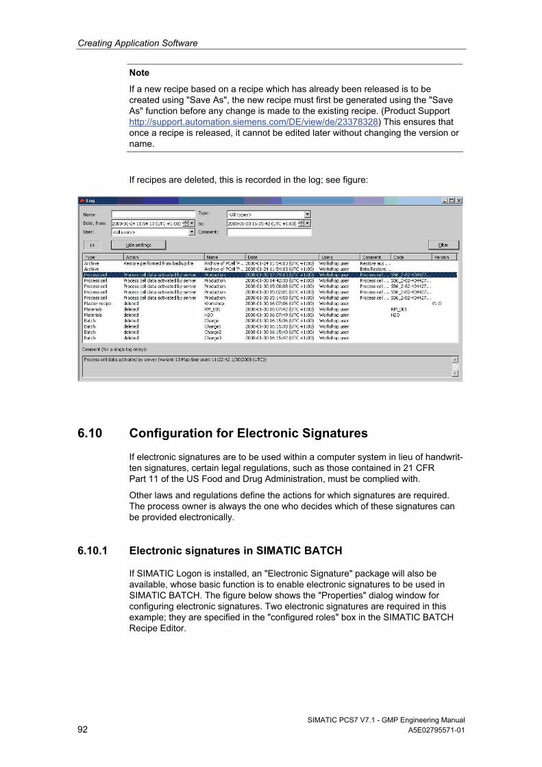
Creating Application Software
SIMATIC PCS7 V7.1 - GMP Engineering Manual 92 A5E02795571-01
Note
If a new recipe based on a recipe which has already been released is to be created using "Save As", the new recipe must first be generated using the "Save As" function before any change is made to the existing recipe. (Product Support http://support.automation.siemens.com/DE/view/de/23378328) This ensures that once a recipe is released, it cannot be edited later without changing the version or name.
If recipes are deleted, this is recorded in the log; see figure:
6.10 Configuration for Electronic Signatures
If electronic signatures are to be used within a computer system in lieu of handwrit-ten signatures, certain legal regulations, such as those contained in 21 CFR Part 11 of the US Food and Drug Administration, must be complied with.
Other laws and regulations define the actions for which signatures are required. The process owner is always the one who decides which of these signatures can be provided electronically.
6.10.1 Electronic signatures in SIMATIC BATCH
If SIMATIC Logon is installed, an "Electronic Signature" package will also be available, whose basic function is to enable electronic signatures to be used in SIMATIC BATCH. The figure below shows the "Properties" dialog window for configuring electronic signatures. Two electronic signatures are required in this example; they are specified in the "configured roles" box in the SIMATIC BATCH Recipe Editor.
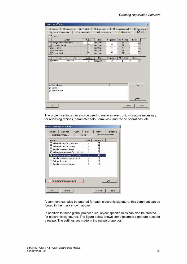
Creating Application Software
SIMATIC PCS7 V7.1 - GMP Engineering Manual A5E02795571-01 93
The project settings can also be used to make an electronic signature necessary for releasing recipes, parameter sets (formulas), and recipe operations, etc.
A comment can also be entered for each electronic signature; this comment can be forced in the mask shown above.
In addition to these global project rules, object-specific rules can also be created for electronic signatures. The figure below shows some example signature rules for a recipe. The settings are made in the recipe properties.
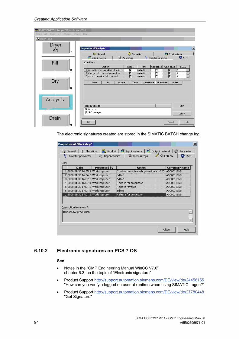
Creating Application Software
SIMATIC PCS7 V7.1 - GMP Engineering Manual 94 A5E02795571-01
The electronic signatures created are stored in the SIMATIC BATCH change log.
6.10.2 Electronic signatures on PCS 7 OS
See
Notes in the “GMP Engineering Manual WinCC V7.0”, chapter 6.3, on the topic of "Electronic signature"
Product Support http://support.automation.siemens.com/DE/view/de/24458155 "How can you verify a logged on user at runtime when using SIMATIC Logon?"
Product Support http://support.automation.siemens.com/DE/view/de/27780448 "Get Signature"
Creating Application Software
SIMATIC PCS7 V7.1 - GMP Engineering Manual A5E02795571-01 95
6.10.3 Electronic signatures on PCS 7 ES
Configuration data in the engineering system is subject to change control and it must be possible to trace any changes made. The requirements of 21 CFR Part 11 regarding audit trails and electronic signatures do not usually apply to engineering systems.
If individual items of data or any inputs or changes made in relation to them have a bearing on quality, they must only be entered via the operator control level (OS) and, if required, assigned an electronic signature at that same location.
6.11 Data Backup
Backup copies of the configuration data must be made at regular intervals during the configuration phase. This ensures that the configuration data which has been created can be accessed again if defective hardware or a defective hard disk has been used, for example.
It is also advisable to make a backup of the system partition containing the operat-ing system, SIMATIC PCS 7 process control system software, etc.
Note
The backup of the user software and the backup of the system partition with and without SIMATIC PCS 7 should be stored on external media (for example, MOD, CD, DVD, network backup).
See also
Chapter 8.1.3 “Regular Data Backups" for operational phase
6.11.1 Backing up the system configuration
Hard disk images should be used to back up the operating system and the PCS 7 installation. These images allow you to restore the original state of PCs.
Which images are advisable?
Creation of an image of the operating system installation with all drivers and all settings for the network, user administration, etc., without SIMATIC PCS 7
Creation of an image of the installed PCs with SIMATIC PCS 7
Creation of an image of the installed PCs with SIMATIC PCS 7, including all projects
Note
An image can only be imported on a PC with identical hardware. For this reason, the hardware configuration of the PC must be suitably documented.
Images of individual partitions cannot be exchanged between PCs because various settings differ from PC to PC, for example those in the registry.
Creating Application Software
SIMATIC PCS7 V7.1 - GMP Engineering Manual 96 A5E02795571-01
6.11.2 Backing up the user software
Backing up user software in the engineering system
It is advisable to back up project data at regular intervals during the configuration phase and when changes are made to released user software. The SIMATIC Manager "Archive Project" system function should be used for this purpose or, if version-specific archiving is required, the "Version Trail" add-on package should be used, see chapter 7.4.1 "Versioning Projects with "Version Trail"".
Note
If data backups are to be created during plant operation, consideration must be given to whether and, if so, which online parameters must be read back prior to generating the backup.
Parameter changes which are not read back will be lost if the system or project is restored.
Backing up recipe data in SIMATIC BATCH
The project configuration must be backed up in PCS 7, as must application data in SIMATIC BATCH (libraries, master recipes, materials, user rights, etc.). This backup is created from within the SIMATC BATCH Control Center.
The backup data can be copied back again using the "Restore" command.
6.12 Recording and Archiving Data Electronically
Several steps have to be performed in order to record and archive data electroni-cally:
Definition of the data to be archived, the archive sizes and the suitable archiv-ing strategy
Set up process value archives for the online saving of selected process values.
Set up parameters for transferring the archives to the archive server (time period or amount of storage space used).
6.12.1 Determining the data to be archived
Various factors must be taken into account when defining the archiving strategy and determining the required storage space, for example:
Definition of the data to be archived: process values, messages, batch data and batch reports, audit trail data, log files, etc.
Definition of the relevant recording cycles
Specification of the period of storage online and offline
Definition of the archiving cycle for transfer to external storage
Creating Application Software
SIMATIC PCS7 V7.1 - GMP Engineering Manual A5E02795571-01 97
In PCS 7, this data is saved in various archives:
Process value archive "Tag Logging fast", archiving of process values <1 min
Process value archive "Tag Logging slow", archiving of process values >1 min
Message archive "Alarm Logging"
OS and batch reports
In other parts of the system, actions are monitored and recorded in log files or databases:
Change log on ES level for "Downloading the target system" and online parameter changes
SIMATIC Logon database "EventLog.mdb"
Event Viewer under Windows Computer Management (logon/logoff activities, account management, permission settings for the file system, etc. according to the corresponding configuration)
Note
All the files mentioned (and others, if required) must be considered in the archiving concept.
6.12.2 Setting up process value archives
The procedure for configuring a process value archive is broken down into the following steps:
Creating the new process value archive and selecting the tags to be stored in the short-term archive.
Configuring the process value archive by specifying or selecting access permission levels or the storage location, for example.
The process value archive is used to record tag-related process values (analog and binary values) in a database in the form of a short-term archive. The size of the short-term archive is defined in the specifications (URS, FS, DS).
Note
The segments in the short-term archive must be created in such a way that they are transferred at regular intervals, ensuring that no data can be lost.
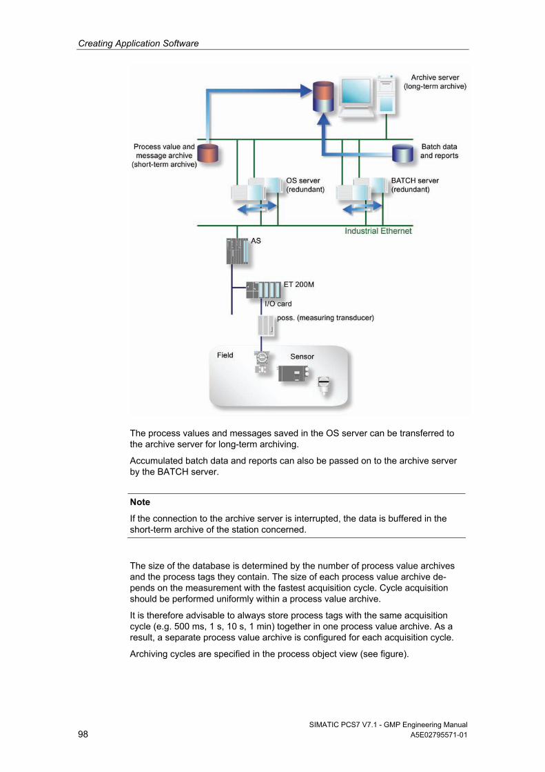
Creating Application Software
SIMATIC PCS7 V7.1 - GMP Engineering Manual 98 A5E02795571-01
The process values and messages saved in the OS server can be transferred to the archive server for long-term archiving.
Accumulated batch data and reports can also be passed on to the archive server by the BATCH server.
Note
If the connection to the archive server is interrupted, the data is buffered in the short-term archive of the station concerned.
The size of the database is determined by the number of process value archives and the process tags they contain. The size of each process value archive de-pends on the measurement with the fastest acquisition cycle. Cycle acquisition should be performed uniformly within a process value archive.
It is therefore advisable to always store process tags with the same acquisition cycle (e.g. 500 ms, 1 s, 10 s, 1 min) together in one process value archive. As a result, a separate process value archive is configured for each acquisition cycle.
Archiving cycles are specified in the process object view (see figure).
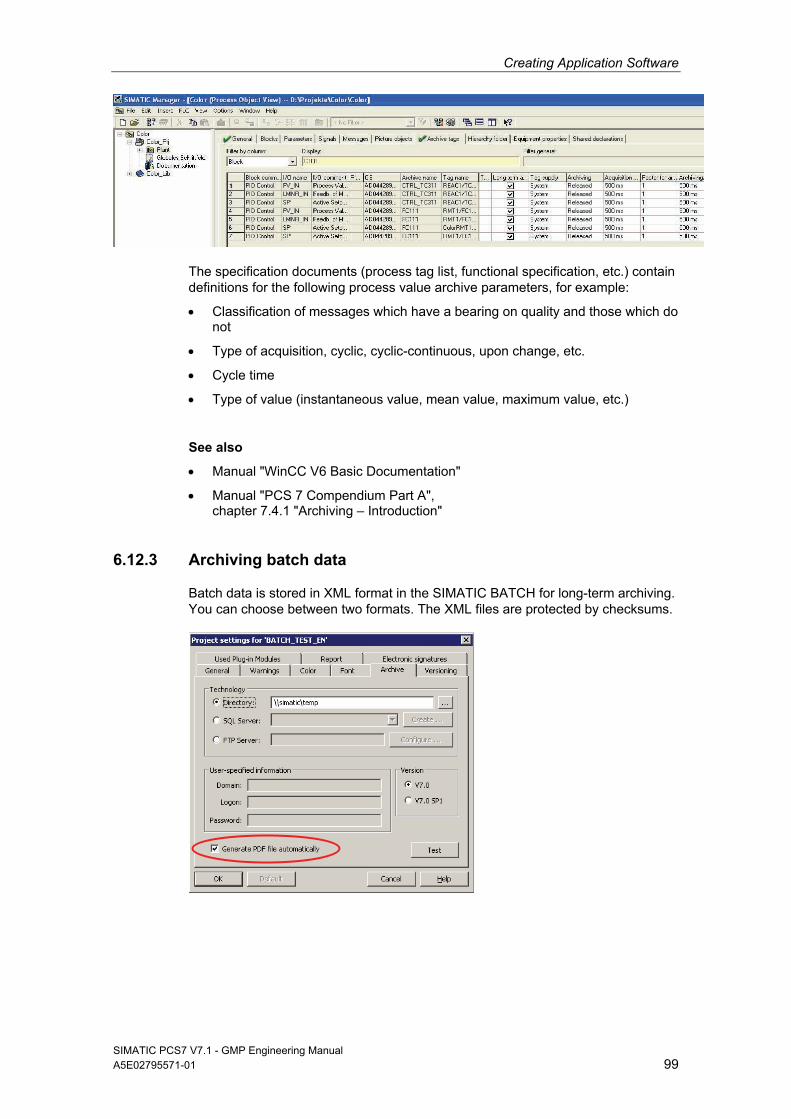
Creating Application Software
SIMATIC PCS7 V7.1 - GMP Engineering Manual A5E02795571-01 99
The specification documents (process tag list, functional specification, etc.) contain definitions for the following process value archive parameters, for example:
Classification of messages which have a bearing on quality and those which do not
Type of acquisition, cyclic, cyclic-continuous, upon change, etc.
Cycle time
Type of value (instantaneous value, mean value, maximum value, etc.)
See also
Manual "WinCC V6 Basic Documentation"
Manual "PCS 7 Compendium Part A", chapter 7.4.1 "Archiving – Introduction"
6.12.3 Archiving batch data
Batch data is stored in XML format in the SIMATIC BATCH for long-term archiving. You can choose between two formats. The XML files are protected by checksums.
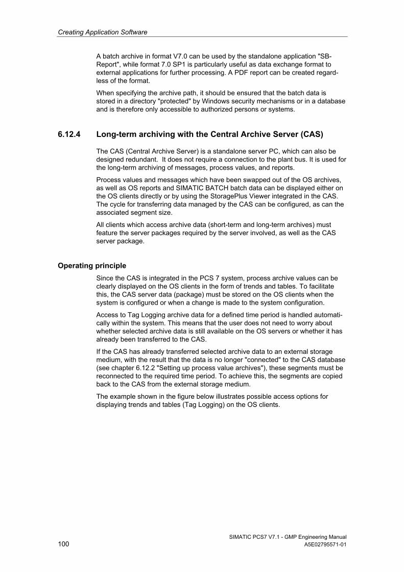
Creating Application Software
SIMATIC PCS7 V7.1 - GMP Engineering Manual 100 A5E02795571-01
A batch archive in format V7.0 can be used by the standalone application "SB-Report", while format 7.0 SP1 is particularly useful as data exchange format to external applications for further processing. A PDF report can be created regard-less of the format.
When specifying the archive path, it should be ensured that the batch data is stored in a directory "protected" by Windows security mechanisms or in a database and is therefore only accessible to authorized persons or systems.
6.12.4 Long-term archiving with the Central Archive Server (CAS)
The CAS (Central Archive Server) is a standalone server PC, which can also be designed redundant. It does not require a connection to the plant bus. It is used for the long-term archiving of messages, process values, and reports.
Process values and messages which have been swapped out of the OS archives, as well as OS reports and SIMATIC BATCH batch data can be displayed either on the OS clients directly or by using the StoragePlus Viewer integrated in the CAS. The cycle for transferring data managed by the CAS can be configured, as can the associated segment size.
All clients which access archive data (short-term and long-term archives) must feature the server packages required by the server involved, as well as the CAS server package.
Operating principle
Since the CAS is integrated in the PCS 7 system, process archive values can be clearly displayed on the OS clients in the form of trends and tables. To facilitate this, the CAS server data (package) must be stored on the OS clients when the system is configured or when a change is made to the system configuration.
Access to Tag Logging archive data for a defined time period is handled automati-cally within the system. This means that the user does not need to worry about whether selected archive data is still available on the OS servers or whether it has already been transferred to the CAS.
If the CAS has already transferred selected archive data to an external storage medium, with the result that the data is no longer "connected" to the CAS database (see chapter 6.12.2 "Setting up process value archives"), these segments must be reconnected to the required time period. To achieve this, the segments are copied back to the CAS from the external storage medium.
The example shown in the figure below illustrates possible access options for displaying trends and tables (Tag Logging) on the OS clients.
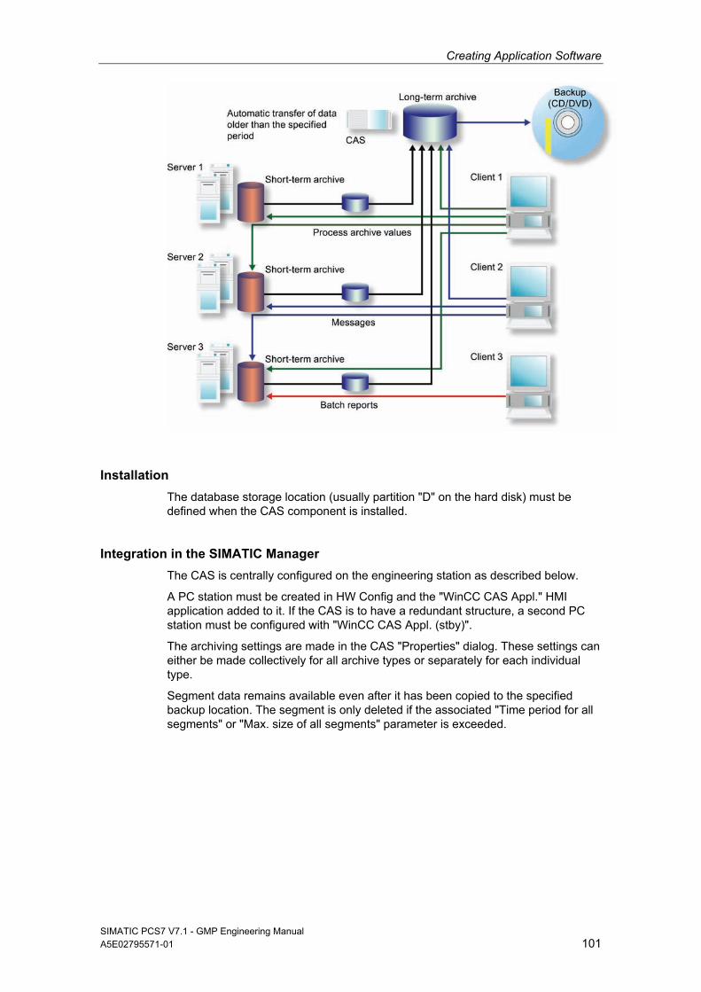
Creating Application Software
SIMATIC PCS7 V7.1 - GMP Engineering Manual A5E02795571-01 101
Installation
The database storage location (usually partition "D" on the hard disk) must be defined when the CAS component is installed.
Integration in the SIMATIC Manager
The CAS is centrally configured on the engineering station as described below.
A PC station must be created in HW Config and the "WinCC CAS Appl." HMI application added to it. If the CAS is to have a redundant structure, a second PC station must be configured with "WinCC CAS Appl. (stby)".
The archiving settings are made in the CAS "Properties" dialog. These settings can either be made collectively for all archive types or separately for each individual type.
Segment data remains available even after it has been copied to the specified backup location. The segment is only deleted if the associated "Time period for all segments" or "Max. size of all segments" parameter is exceeded.
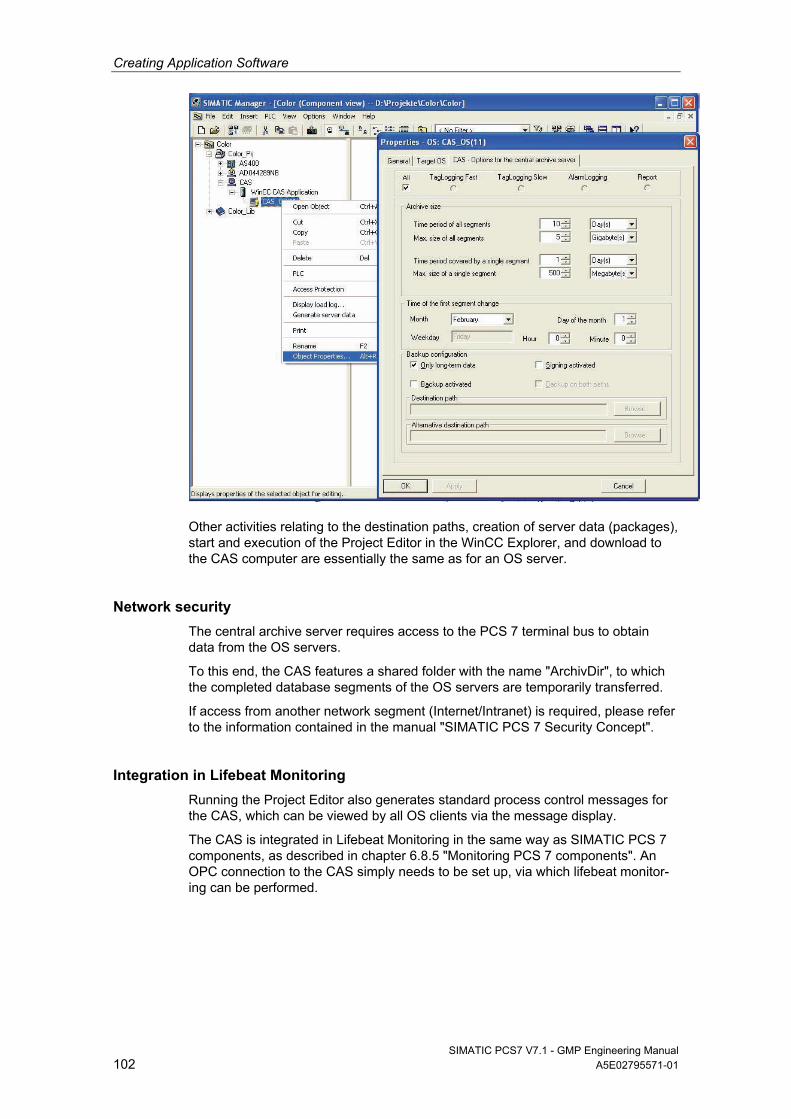
Creating Application Software
SIMATIC PCS7 V7.1 - GMP Engineering Manual 102 A5E02795571-01
Other activities relating to the destination paths, creation of server data (packages), start and execution of the Project Editor in the WinCC Explorer, and download to the CAS computer are essentially the same as for an OS server.
Network security
The central archive server requires access to the PCS 7 terminal bus to obtain data from the OS servers.
To this end, the CAS features a shared folder with the name "ArchivDir", to which the completed database segments of the OS servers are temporarily transferred.
If access from another network segment (Internet/Intranet) is required, please refer to the information contained in the manual "SIMATIC PCS 7 Security Concept".
Integration in Lifebeat Monitoring
Running the Project Editor also generates standard process control messages for the CAS, which can be viewed by all OS clients via the message display.
The CAS is integrated in Lifebeat Monitoring in the same way as SIMATIC PCS 7 components, as described in chapter 6.8.5 "Monitoring PCS 7 components". An OPC connection to the CAS simply needs to be set up, via which lifebeat monitor-ing can be performed.
Creating Application Software
SIMATIC PCS7 V7.1 - GMP Engineering Manual A5E02795571-01 103
Visualization of CAS data
Archived process values can be displayed on OS clients in the form of trends or tables.
In order to visualize messages, the integrated "StoragePlus Viewer" software package is used to define views of CAS databases. The data made available in this way is published using the Internet Information Server and can be viewed over an Intranet.
Audit Trail
It is not technically possible to modify the data archived by the CAS, as the StoragePlus Viewer only provides users with read access to the archived data. CAS therefore does not support an audit trail in accordance with 21 CFR Part 11. All events, for example the transfer of data to external media or failed transfers, are however saved in the log file directory on CAS.
Archiving
Process data is initially archived locally in single segments on the PCS 7 OS servers in Tag Logging or Alarm Logging. Once a single segment is completed, it is copied to the CAS. If the CAS has a redundant configuration, the single segment is copied to both computers.
Note
The period for single segments on the OS servers in Tag Logging must be configured to be significantly shorter than the period for single segments of the CAS.
See also
Configuration manual "PCS 7 V7.1 Operator Station"
Manual "PCS 7 Compendium Part A", chapters 7.4.4 und 7.4.5 "CAS"
Product Support http://support.automation.siemens.com/DE/view/de/37022157 "Installation of CAS"
6.12.5 Long-term archiving with StoragePlus
StoragePlus consists of three software components:
The "Administrator Console" (server application) allows the user to assign rights. Database settings and backups are also configured here. Access should be restricted to an authorized group of people.
The "StoragePlus View Editor" is used to configure trends, messages, and batch reports, which are saved in a separate view.
The "StoragePlus WebViewer" is used to display views that are produced using the View Editor and have been published for this form of viewing.
Creating Application Software
SIMATIC PCS7 V7.1 - GMP Engineering Manual 104 A5E02795571-01
Operating principle
StoragePlus collects completed archive data segments from the servers together in a separate database according to chronological criteria so that they can be transferred to CD or DVD when a certain user-defined size is reached.
The database segments that result from the StoragePlus archiving procedure have the status "connected", which changes to "disconnected" when they are trans-ferred. For StoragePlus to display archive values, the database segments must be "connected".
Archive data that has already been transferred can be "connected" to the Storage-Plus database again. The "Catalog" call integrated in the administrator console in StoragePlus provides an overview of the current status of the database segments.
Installation
StoragePlus is based on the MS SQL server.
The installation instructions include detailed information on the installation order which must be followed and on the selection of partitions.
Access protection
The following default user groups exist in the StoragePlus administrator console:
Administrator – full access to the StoragePlus system
Power user – can read and create StoragePlus views
User – can read StoragePlus views
Guest – has no rights, neither access to StoragePlus views nor to the StoragePlus system
It is advisable to assign each user to just one group.
StoragePlus receives archive data and reports from the OS servers / BATCH server via the PCS 7 terminal bus. A shared folder called "ArchivDir", is provided for this purpose, where this data is stored by means of file transfer.
The user who creates a view also has further editing rights for that view. This right can also be assigned to other users by means of the administrator console.
Audit Trail
Technically, it is not possible to modify data archived in StoragePlus, as the StoragePlus Viewer only provides users with read access to the archived data. This means that StoragePlus does not support an audit trail in the sense of 21 CFR Part 11. User activities performed in the View Editor and StoragePlus application events are nevertheless recorded in log files.
Application log presents the recorded events, when archives are connected/ disconnected, for example.
Activity log contains events, such as changes to the configuration or the publication of views.
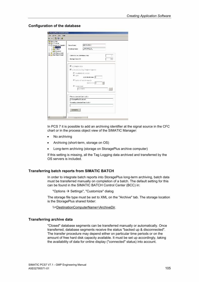
Creating Application Software
SIMATIC PCS7 V7.1 - GMP Engineering Manual A5E02795571-01 105
Configuration of the database
In PCS 7 it is possible to add an archiving identifier at the signal source in the CFC chart or in the process object view of the SIMATIC Manager:
No archiving
Archiving (short-term, storage on OS)
Long-term archiving (storage on StoragePlus archive computer)
If this setting is missing, all the Tag Logging data archived and transferred by the OS servers is included.
Transferring batch reports from SIMATIC BATCH
In order to integrate batch reports into StoragePlus long-term archiving, batch data must be transferred manually on completion of a batch. The default setting for this can be found in the SIMATIC BATCH Control Center (BCC) in:
"Options Settings", "Customize" dialog
The storage file type must be set to XML on the "Archive" tab. The storage location is the StoragePlus shared folder:
\\<DestinationComputerName>\ArchiveDir.
Transferring archive data
"Closed" database segments can be transferred manually or automatically. Once transferred, database segments receive the status "backed up & disconnected". The transfer procedure may depend either on particular time periods or on the amount of free hard disk capacity available. It must be set up accordingly, taking the availability of data for online display ("connected" status) into account.
Creating Application Software
SIMATIC PCS7 V7.1 - GMP Engineering Manual 106 A5E02795571-01
Backing up configuration data
StoragePlus maintains a table of contents of all database files which have been created, without which archived data could not be accessed. This table of contents, along with the created views and other system settings, is needed in order to restore the system and must, therefore, be stored using the "Configuration Data" -> "Save" button.
Recommendation
This configuration data must be saved regularly, for example, each time archive data is transferred.
See also
Manual "PCS 7 Compendium Part A", chapter 7.4.6 "StoragePlus"
6.13 Uninterruptible Power Supply (UPS)
UPS systems are necessary so that process and audit trail data, for example, can continue to be recorded during power failures. The design of the UPS must be agreed with the system user and specified accordingly. The following items must be noted here:
Energy consumption of systems to be supplied
Performance capability of the UPS
Desired duration of the UPS buffering
The energy consumption of the systems to be buffered determines the size of the UPS. A further selection criterion is the priority of the systems. Systems with higher priority are:
Automation system (AS)
Archiving server
Operator station (OS) server
Operator station (OS) clients
Network components
In any case, it is important to include the systems for data logging in the buffering procedurte. The logging should also record the time of the power failure.
The use of UPS systems is linked to the installation and configuration of software. The following must be taken into account:
Configuration of alarms regarding power failure
Determination of the time frame for shutting down the PC
Specification of the time frame of the UPS buffering
The process control system must be programmed so that it is brought to a safe state after a specified buffer time in the event of a power failure.
Creating Application Software
SIMATIC PCS7 V7.1 - GMP Engineering Manual A5E02795571-01 107
6.13.1 Configuration of a UPS
The following table contains an example of the configuration of an uninterruptible power supply for an operator station in a process control system. The same basic procedure can be used with automation stations.
Scenario Action Reaction
1 Power failure < 10 seconds
The process control system computers are buffered by the UPS. An alarm using a digital input in the process control system documents the power failure.
2 Power failure >20 minutes. Power returns after 25 minutes
The process control system computers are buffered by the UPS, e.g., for 20 minutes. An alarm in the process control system documents the power failure and the shutdown of the process control system after 20 minutes. The UPS stops supplying power after a defined time (for example, 25 minutes) so that an independent restart of the process control system computers is possible once the power has been restored.
3 Power failure > 1 hour
The process control system computers are buffered by the UPS, e.g. for 20 minutes. An alarm in the process control system documents the power failure and the shutdown of the process control system after 20 minutes. The UPS stops supplying power after a defined hold time to ensure that the process control system computers can restart independently after restoration of power.
6.13.2 UPS configuration via digital inputs
In addition to the standard buffering provided by UPS devices, the option of monitoring the power supplies should be used. In this case, the phase is monitored via one or several digital inputs. The failure of the energy supply can be registered via alarm messages and archived during production in the batch report. This guarantees a complete record of the plant problems.
UPS buffering of load voltage
The automation CPU is supplied with power by the UPS 24 V module both during voltage dips and longer power failures. The phase monitoring module monitors the status change during a power failure using a digital input that should be designed as a fail-safe input signal. If a power failure occurs, an additional alarm can be generated to inform the operator of the power failure (alarm message). By logging it in the message system, this power failure can be used for subsequent investiga-tions.
With power failure concepts, safe states can also be implemented immediately or after a certain delay (for example, equipment phase hold, establishing a safe plant status even after power has returned, etc.).
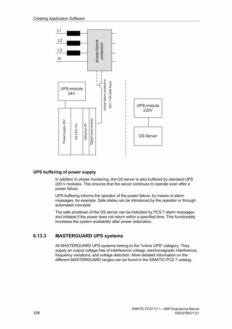
Creating Application Software
SIMATIC PCS7 V7.1 - GMP Engineering Manual 108 A5E02795571-01
UPS buffering of power supply
In addition to phase monitoring, the OS server is also buffered by standard UPS 220 V modules. This ensures that the server continues to operate even after a power failure.
UPS buffering informs the operator of the power failure, by means of alarm messages, for example. Safe states can be introduced by the operator or through automated concepts.
The safe shutdown of the OS server can be indicated by PCS 7 alarm messages and initiated if the power does not return within a specified time. This functionality increases the system availability after power restoration.
6.13.3 MASTERGUARD UPS systems
All MASTERGUARD UPS systems belong to the "online UPS" category. They supply an output voltage free of interference voltage, electromagnetic interference, frequency variations, and voltage distortion. More detailed information on the different MASTERGUARD ranges can be found in the SIMATIC PCS 7 catalog.
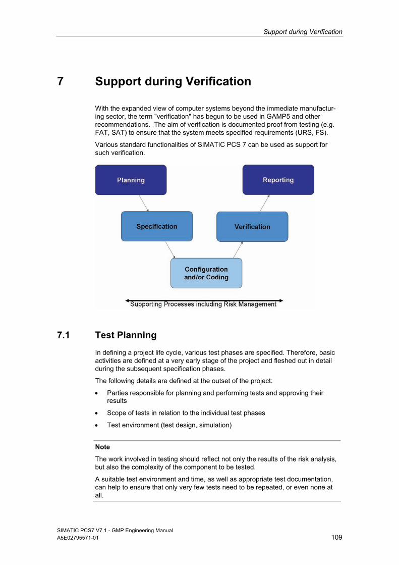
Support during Verification
SIMATIC PCS7 V7.1 - GMP Engineering Manual A5E02795571-01 109
7 Support during Verification
With the expanded view of computer systems beyond the immediate manufactur-ing sector, the term "verification" has begun to be used in GAMP5 and other recommendations. The aim of verification is documented proof from testing (e.g. FAT, SAT) to ensure that the system meets specified requirements (URS, FS).
Various standard functionalities of SIMATIC PCS 7 can be used as support for such verification.
7.1 Test Planning
In defining a project life cycle, various test phases are specified. Therefore, basic activities are defined at a very early stage of the project and fleshed out in detail during the subsequent specification phases.
The following details are defined at the outset of the project:
Parties responsible for planning and performing tests and approving their results
Scope of tests in relation to the individual test phases
Test environment (test design, simulation)
Note
The work involved in testing should reflect not only the results of the risk analysis, but also the complexity of the component to be tested.
A suitable test environment and time, as well as appropriate test documentation, can help to ensure that only very few tests need to be repeated, or even none at all.
Support during Verification
SIMATIC PCS7 V7.1 - GMP Engineering Manual 110 A5E02795571-01
The individual tests are planned in detail at the same time as the system specifica-tions (FS, DS) are compiled. The following are defined:
Procedures for the individual tests
Test methods, e.g. structural (code review) or functional (black box test)
7.2 Verification of Hardware
Tests are performed to verify whether the installed components and the overall system design meet the requirements of the Design Specification. This covers such aspects as component designations, firmware/product version, location, server and clients used, interfaces, etc.
Note
Printouts and screenshots can each be used as evidence.
A visual inspection of the hardware can also be performed.
Verification of field devices
Field devices are specified and tested by means of the following information, for example:
Identification of manufacturer and type
Order number
Function/installation location
Process tag name/measuring range/unit of measure
Type of connection
Address number
Note
SIMATIC PCS 7 Asset Management can offer support here.
Verification of the automation hardware
Automation stations are specified and tested by means of the following information, for example:
Identification of manufacturer and type
Order number
Number of racks
Verification of the hardware components used (CPU, CP, etc.)
Number of distributed I/O stations
Interfaces to third-party systems
Address number
Support during Verification
SIMATIC PCS7 V7.1 - GMP Engineering Manual A5E02795571-01 111
Note
HW Config printouts support the relevant documentation.
The control cabinet documentation must also comply with HW Config.
Verification of the network structure
The information below is an example of the data which should be specified and tested for verification of the network structure:
Name of station, PC, AS, clients, etc.
Communication module, type of connection, and communication partner (Ethernet, PROFIBUS, serial, etc.)
MAC address (when using the ISO protocol on the plant bus)
TCP/IP address and subnet mask (when using clients)
PROFIBUS addresses
Note
The SIMATIC NetPro configuration can be printed out.
Verification of the employed PC hardware
The information below is an example of the data which should be specified and tested for verification of the PC hardware:
Manufacturer/type designation/essential components
Additionally installed hardware components (additional network adapter, printer, etc.)
Verification of the configured network addresses, screen resolution, etc.
Note
Utilities can read detailed information about the configuration of the computer and print it as a documented proof.
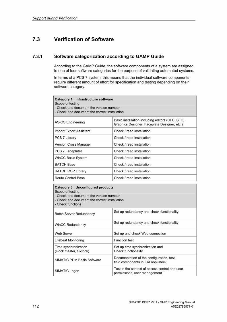
Support during Verification
SIMATIC PCS7 V7.1 - GMP Engineering Manual 112 A5E02795571-01
7.3 Verification of Software
7.3.1 Software categorization according to GAMP Guide
According to the GAMP Guide, the software components of a system are assigned to one of four software categories for the purpose of validating automated systems.
In terms of a PCS 7 system, this means that the individual software components require different amount of effort for specification and testing depending on their software category.
Category 1 : Infrastructure software Scope of testing: - Check and document the version number - Check and document the correct installation
AS-OS Engineering Basic installation including editors (CFC, SFC, Graphics Designer, Faceplate Designer, etc.)
Import/Export Assistant Check / read installation
PCS 7 Library Check / read installation
Version Cross Manager Check / read installation
PCS 7 Faceplates Check / read installation
WinCC Basic System Check / read installation
BATCH Base Check / read installation
BATCH ROP Library Check / read installation
Route Control Base Check / read installation
Category 3 : Unconfigured products Scope of testing: - Check and document the version number - Check and document the correct installation - Check functions
Batch Server Redundancy Set up redundancy and check functionality
WinCC Redundancy Set up redundancy and check functionality
Web Server Set up and check Web connection
Lifebeat Monitoring Function test
Time synchronization (clock master, Siclock)
Set up time synchronization and Check functionality
SIMATIC PDM Basis Software Documentation of the configuration, test field components in IQ/LoopCheck
SIMATIC Logon Test in the context of access control and user permissions, user management
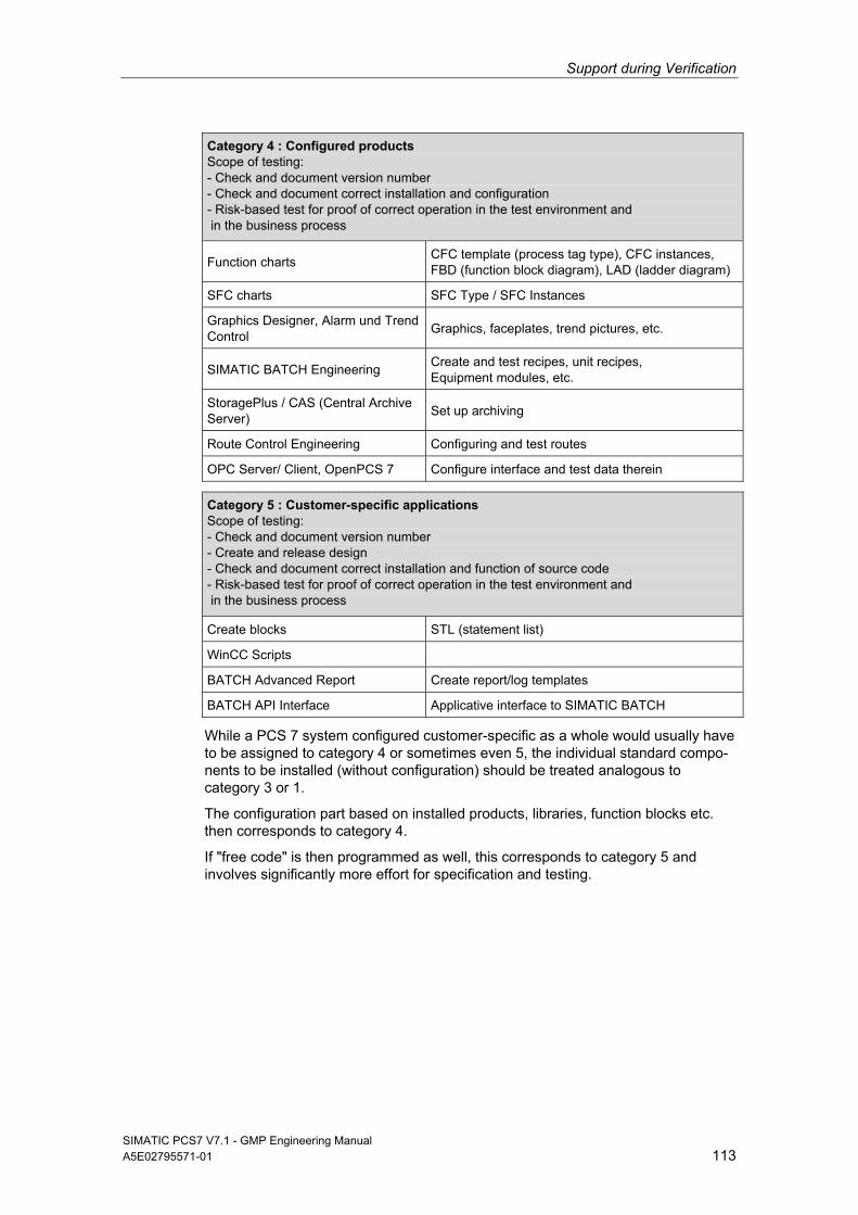
Support during Verification
SIMATIC PCS7 V7.1 - GMP Engineering Manual A5E02795571-01 113
Category 4 : Configured products Scope of testing: - Check and document version number - Check and document correct installation and configuration - Risk-based test for proof of correct operation in the test environment and in the business process
Function charts CFC template (process tag type), CFC instances, FBD (function block diagram), LAD (ladder diagram)
SFC charts SFC Type / SFC Instances
Graphics Designer, Alarm und Trend Control
Graphics, faceplates, trend pictures, etc.
SIMATIC BATCH Engineering Create and test recipes, unit recipes, Equipment modules, etc.
StoragePlus / CAS (Central Archive Server)
Set up archiving
Route Control Engineering Configuring and test routes
OPC Server/ Client, OpenPCS 7 Configure interface and test data therein
Category 5 : Customer-specific applications Scope of testing: - Check and document version number - Create and release design - Check and document correct installation and function of source code - Risk-based test for proof of correct operation in the test environment and in the business process
Create blocks STL (statement list)
WinCC Scripts
BATCH Advanced Report Create report/log templates
BATCH API Interface Applicative interface to SIMATIC BATCH
While a PCS 7 system configured customer-specific as a whole would usually have to be assigned to category 4 or sometimes even 5, the individual standard compo-nents to be installed (without configuration) should be treated analogous to category 3 or 1.
The configuration part based on installed products, libraries, function blocks etc. then corresponds to category 4.
If "free code" is then programmed as well, this corresponds to category 5 and involves significantly more effort for specification and testing.
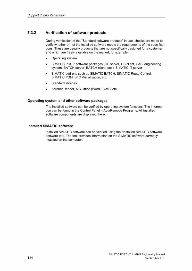
Support during Verification
SIMATIC PCS7 V7.1 - GMP Engineering Manual 114 A5E02795571-01
7.3.2 Verification of software products
During verification of the "Standard software products" in use, checks are made to verify whether or not the installed software meets the requirements of the specifica-tions. These are usually products that are not specifically designed for a customer and which are freely available on the market, for example:
Operating system
SIMATIC PCS 7 software packages (OS server, OS client, CAS, engineering system, BATCH server, BATCH client, etc.), SIMATIC IT server
SIMATIC add-ons such as SIMATIC BATCH, SIMATIC Route Control, SIMATIC PDM, SFC Visualization, etc.
Standard libraries
Acrobat Reader, MS Office (Word, Excel), etc.
Operating system and other software packages
The installed software can be verified by operating system functions. The informa-tion can be found in the Control Panel > Add/Remove Programs. All installed software components are displayed there.
Installed SIMATIC software
Installed SIMATIC software can be verified using the "Installed SIMATIC software" software tool. The tool provides information on the SIMATIC software currently installed on the computer.
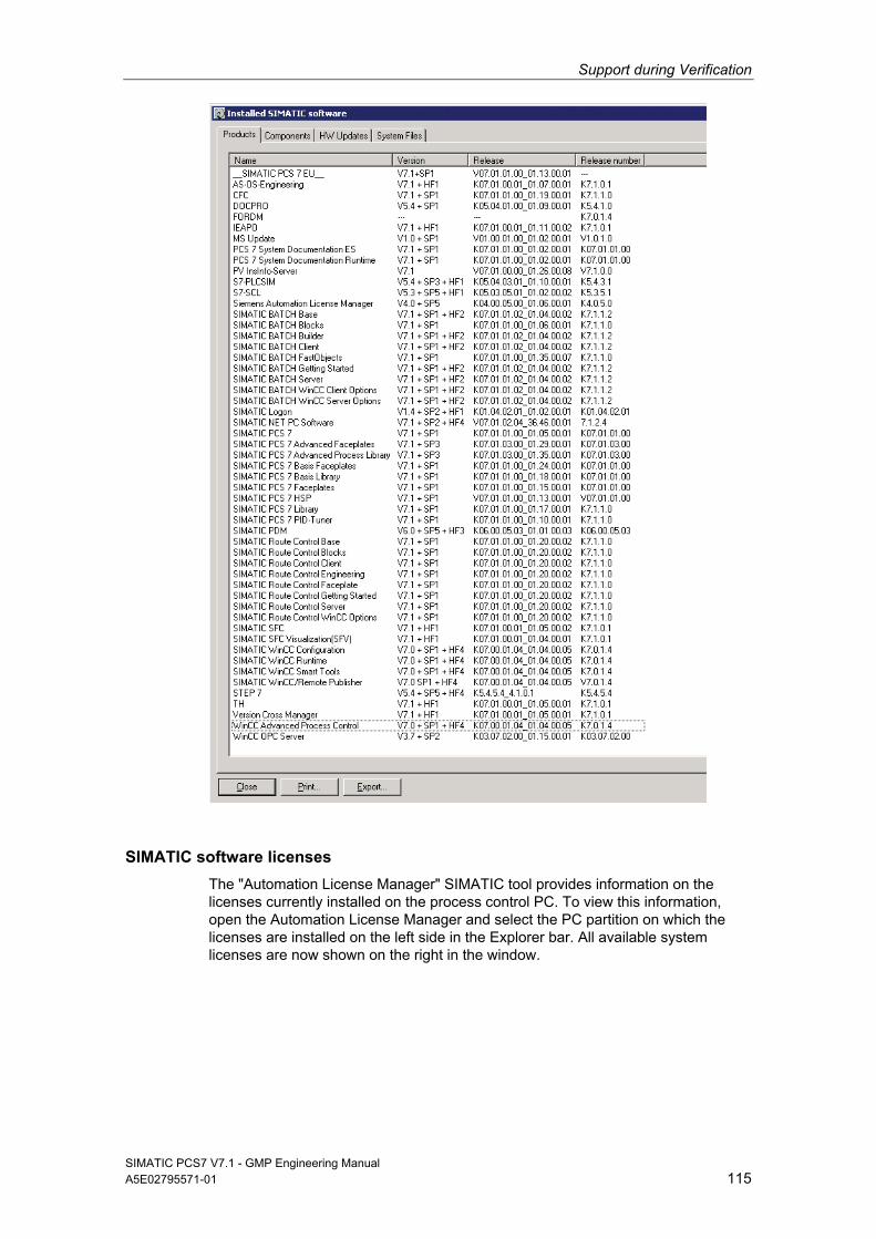
Support during Verification
SIMATIC PCS7 V7.1 - GMP Engineering Manual A5E02795571-01 115
SIMATIC software licenses
The "Automation License Manager" SIMATIC tool provides information on the licenses currently installed on the process control PC. To view this information, open the Automation License Manager and select the PC partition on which the licenses are installed on the left side in the Explorer bar. All available system licenses are now shown on the right in the window.
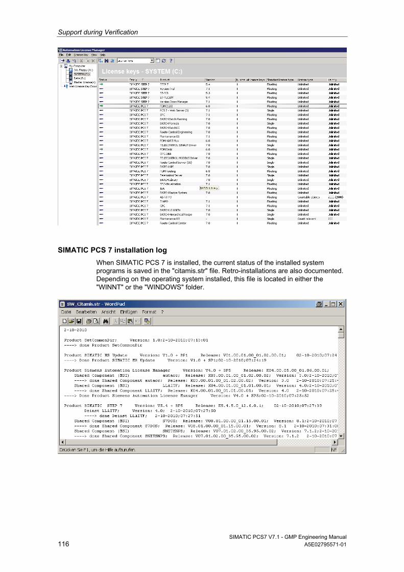
Support during Verification
SIMATIC PCS7 V7.1 - GMP Engineering Manual 116 A5E02795571-01
SIMATIC PCS 7 installation log
When SIMATIC PCS 7 is installed, the current status of the installed system programs is saved in the "citamis.str" file. Retro-installations are also documented. Depending on the operating system installed, this file is located in either the "WINNT" or the "WINDOWS" folder.
Support during Verification
SIMATIC PCS7 V7.1 - GMP Engineering Manual A5E02795571-01 117
7.3.3 Verification of the application software
During verification of the application software, checks are made to verify whether or not the created software meets the requirements of the specifications (FS/DS). You need to consult with the user to agree upon and create the test descriptions (for example for FAT/SAT). These descriptions must take into account the com-plexity of the software and the design specifications.
The aspects listed below are usually tested, therefore this list can be used as a reference for qualification:
Check the name of the application software
Check the technological hierarchy (plant, unit, equipment modules, individual control element etc.)
Software module test (typical test)
Check the communication with other nodes (third-party controllers, MES systems, etc.)
Check all inputs and outputs
Check all control modules (individual control level)
Check all equipment phases and equipment operations (technical functions)
Check the relationships between operating modes (MANUAL/AUTOMATIC switchovers, interlocks, start, running, stopped, aborting, completed, etc.)
Check the process tag names
Check the visualization structure (P&I representation)
Check the operator control policies (access control, group permissions, user permissions)
Check the archiving concepts (short-term archives, long-term archives)
Check the message concept
Check the trends, curves
Check the time synchronization
Note
If other blocks are needed in addition to the PCS 7 standard libraries in order to configure specific processes or functions, the block libraries (FB, FC, DB) of the PCS 7 add-on catalog should be used if possible.
If blocks created by the user are to be employed, significantly more work will be required in terms of specification, creation, and validation; this fact should be taken into consideration.
The process object view can be used for testing revisions for valida-tion/qualification purposes. The software versions can also be modified there (see figure).
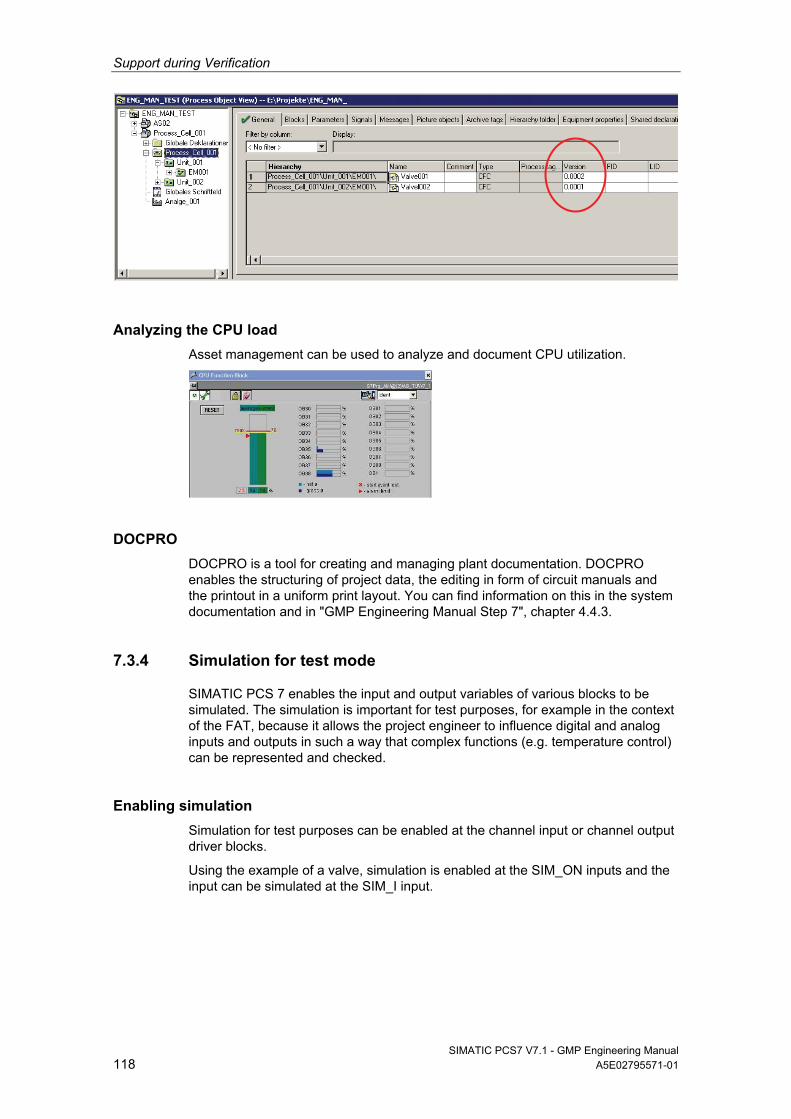
Support during Verification
SIMATIC PCS7 V7.1 - GMP Engineering Manual 118 A5E02795571-01
Analyzing the CPU load
Asset management can be used to analyze and document CPU utilization.
DOCPRO
DOCPRO is a tool for creating and managing plant documentation. DOCPRO enables the structuring of project data, the editing in form of circuit manuals and the printout in a uniform print layout. You can find information on this in the system documentation and in "GMP Engineering Manual Step 7", chapter 4.4.3.
7.3.4 Simulation for test mode
SIMATIC PCS 7 enables the input and output variables of various blocks to be simulated. The simulation is important for test purposes, for example in the context of the FAT, because it allows the project engineer to influence digital and analog inputs and outputs in such a way that complex functions (e.g. temperature control) can be represented and checked.
Enabling simulation
Simulation for test purposes can be enabled at the channel input or channel output driver blocks.
Using the example of a valve, simulation is enabled at the SIM_ON inputs and the input can be simulated at the SIM_I input.
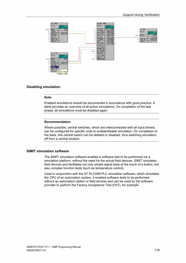
Support during Verification
SIMATIC PCS7 V7.1 - GMP Engineering Manual A5E02795571-01 119
Disabling simulation
Note
Enabled simulations should be documented in accordance with good practice. A table provides an overview of all active simulations. On completion of the test phase, all simulations must be disabled again.
Recommendation
Where possible, central switches, which are interconnected with all input drivers, can be configured for specific units to enable/disable simulation. On completion of the tests, this central switch can be deleted or disabled, thus switching simulation off from a central location.
SIMIT simulation software
The SIMIT simulation software enables a software test to be performed via a simulation platform, without the need for the actual field devices. SIMIT simulates field devices and facilitates not only simple signal tests at the touch of a button, but also complex function tests (such as temperature control).
Used in conjunction with the S7 PLCSIM PLC simulation software, which simulates the CPU of an automation system, it enables software tests to be performed without an automation station or field devices and can be used by the software provider to perform the Factory Acceptance Test (FAT), for example.
Support during Verification
SIMATIC PCS7 V7.1 - GMP Engineering Manual 120 A5E02795571-01
7.4 Configuration Control
7.4.1 Versioning Projects with "Version Trail"
SIMATIC PCS 7 Version Trail can be used to archive multiprojects, single projects, and project-specific libraries with a unique version ID. Archiving is performed in accordance with the PCS 7 archiving procedure. Project-specific libraries are also saved when a multiproject is archived, which means they remain assigned to the relevant multiproject.
SIMATIC PCS 7 Version Trail ensures continuous incrementation of the version according to validation factors. A completed version can no longer be changed. However, every archived version can be read back into the system.
Since GMP requirements demand that SIMATIC Logon be used, all relevant actions are saved with details of the logged-on user.
Note
Before a multiproject is archived, a check must be performed to ensure that no projects or libraries belonging to the multiproject have been removed. This is because only projects and libraries contained in the multiproject at the time of archiving will actually be archived.
For more information, see Online Help of SIMATIC PCS 7, the topic of "Version Trail", and the configuration manual "PCS 7 Engineering System".
Procedure for archiving projects
Each archived project version can be retrieved in the SIMATIC Manager or by using Version Trail. In a validated plant, however, previous project versions can only be read back (retrieved) in exceptional cases and in consultation with the plant operator.
Note
The projects to be archived must not be opened in the SIMATIC Manager.
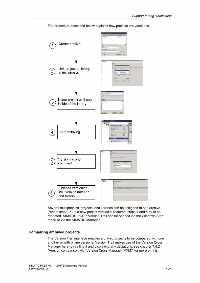
Support during Verification
SIMATIC PCS7 V7.1 - GMP Engineering Manual A5E02795571-01 121
The procedure described below explains how projects are versioned.
Several multiprojects, projects, and libraries can be assigned to one archive (repeat step 2-5). If a new project version is required, steps 4 and 5 must be repeated. SIMATIC PCS 7 Version Trail can be opened via the Windows Start menu or via the SIMATIC Manager.
Comparing archived projects
The Version Trail interface enables archived projects to be compared with one another or with online versions. Version Trail makes use of the Version Cross Manager here, by calling it and displaying any deviations, see chapter 7.4.2 "Version comparison with Version Cross Manager (VXM)" for more on this.
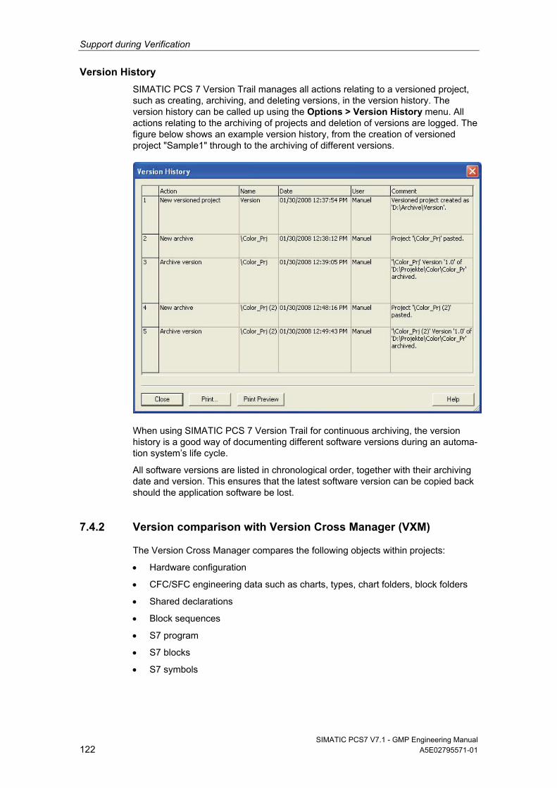
Support during Verification
SIMATIC PCS7 V7.1 - GMP Engineering Manual 122 A5E02795571-01
Version History
SIMATIC PCS 7 Version Trail manages all actions relating to a versioned project, such as creating, archiving, and deleting versions, in the version history. The version history can be called up using the Options > Version History menu. All actions relating to the archiving of projects and deletion of versions are logged. The figure below shows an example version history, from the creation of versioned project "Sample1" through to the archiving of different versions.
When using SIMATIC PCS 7 Version Trail for continuous archiving, the version history is a good way of documenting different software versions during an automa-tion system’s life cycle.
All software versions are listed in chronological order, together with their archiving date and version. This ensures that the latest software version can be copied back should the application software be lost.
7.4.2 Version comparison with Version Cross Manager (VXM)
The Version Cross Manager compares the following objects within projects:
Hardware configuration
CFC/SFC engineering data such as charts, types, chart folders, block folders
Shared declarations
Block sequences
S7 program
S7 blocks
S7 symbols
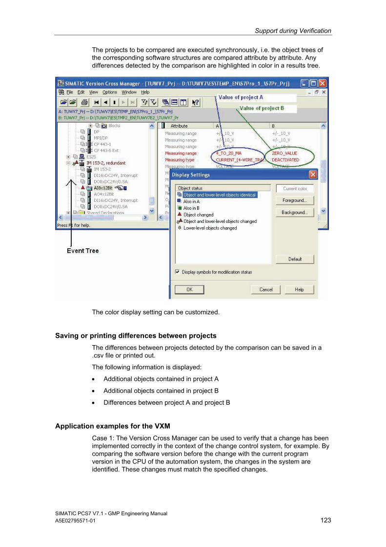
Support during Verification
SIMATIC PCS7 V7.1 - GMP Engineering Manual A5E02795571-01 123
The projects to be compared are executed synchronously, i.e. the object trees of the corresponding software structures are compared attribute by attribute. Any differences detected by the comparison are highlighted in color in a results tree.
The color display setting can be customized.
Saving or printing differences between projects
The differences between projects detected by the comparison can be saved in a .csv file or printed out.
The following information is displayed:
Additional objects contained in project A
Additional objects contained in project B
Differences between project A and project B
Application examples for the VXM
Case 1: The Version Cross Manager can be used to verify that a change has been implemented correctly in the context of the change control system, for example. By comparing the software version before the change with the current program version in the CPU of the automation system, the changes in the system are identified. These changes must match the specified changes.
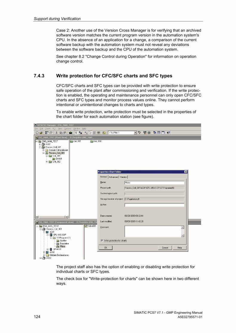
Support during Verification
SIMATIC PCS7 V7.1 - GMP Engineering Manual 124 A5E02795571-01
Case 2: Another use of the Version Cross Manager is for verifying that an archived software version matches the current program version in the automation system's CPU. In the absence of an application for a change, a comparison of the current software backup with the automation system must not reveal any deviations between the software backup and the CPU of the automation system.
See chapter 8.2 "Change Control during Operation" for information on operation change control.
7.4.3 Write protection for CFC/SFC charts and SFC types
CFC/SFC charts and SFC types can be provided with write protection to ensure safe operation of the plant after commissioning and verification. If the write protec-tion is enabled, the operating and maintenance personnel can only open CFC/SFC charts and SFC types and monitor process values online. They cannot perform intentional or unintentional changes to charts and types.
To enable write protection, write protection must be selected in the properties of the chart folder for each automation station (see figure).
The project staff also has the option of enabling or disabling write protection for individual charts or SFC types.
The check box for "Write-protection for charts" can be shown here in two different ways.
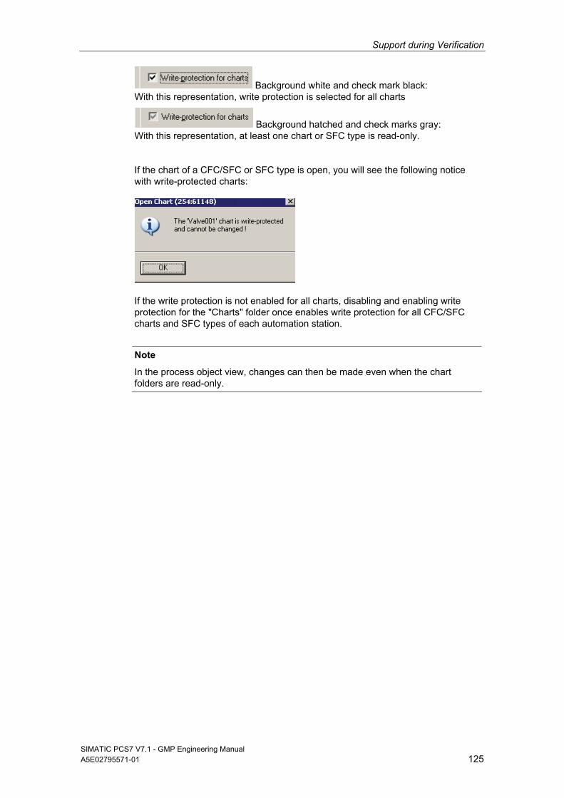
Support during Verification
SIMATIC PCS7 V7.1 - GMP Engineering Manual A5E02795571-01 125
Background white and check mark black: With this representation, write protection is selected for all charts
Background hatched and check marks gray: With this representation, at least one chart or SFC type is read-only.
If the chart of a CFC/SFC or SFC type is open, you will see the following notice with write-protected charts:
If the write protection is not enabled for all charts, disabling and enabling write protection for the "Charts" folder once enables write protection for all CFC/SFC charts and SFC types of each automation station.
Note
In the process object view, changes can then be made even when the chart folders are read-only.
Operation, Maintenance and Servicing
SIMATIC PCS7 V7.1 - GMP Engineering Manual 126 A5E02795571-01
8 Operation, Maintenance and Servicing
8.1 Operation and Monitoring
8.1.1 Process visualization
SIMATIC PCS 7 provides extensive process visualization. Individually configured user interfaces can be created for each application – for reliable process control and optimization of the entire production sequence.
Runtime data can be output by the system based on reports.
8.1.2 Asset management
In the context of process engineering, asset management aims to use appropriate methods to ensure that a production plant benefits from maximum availability at the lowest possible operating costs. The most efficient strategy is without doubt status-oriented maintenance, which must be based on a status detection procedure that is as continuous as possible. Asset management relies on having access to precise information relating to the current plant status, which can then be used to deter-mine exactly which maintenance activities need to be carried where and at what time.
Implementation in PCS 7
The asset management integrated in SIMATIC PCS 7 is used for plant mainte-nance. Additional hardware and software tools are not required. Plant operators and maintenance engineers use the same SIMATIC PCS 7 tools and user inter-faces, along with information which has been filtered and prepared according to the field of activity concerned. While the plant operators operate and monitor the process on the PCS 7 operator station (OS), the maintenance engineer uses the maintenance station (MS) to control the hardware structure of the production facility in order to handle the diagnostics and maintenance requirements.
The various components of a PCS 7 plant can be monitored with the diagnostic and maintenance functions integrated in SIMATIC PCS 7. The maintenance engineers access to all details of the components and devices when needed, beginning with an overview display (plant view). The overview display uses the standardized symbols to visualize the condition of a component itself and also provides collective information on the conditions of all devices in the lower-level hierarchies. The group status message shows the OK condition or the seriousness of a possible problem in red, yellow, or green, similar to a traffic light.
In the diagnostic faceplate, a monitored component can request maintenance services. The status of the work can also be specified. This is recorded in the form of an operating message and indicated by the symbols. A work instruction number and a comment can be entered for each work request.
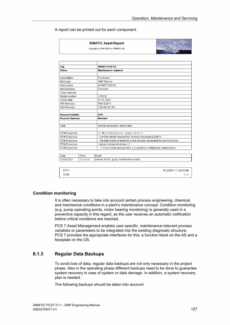
Operation, Maintenance and Servicing
SIMATIC PCS7 V7.1 - GMP Engineering Manual A5E02795571-01 127
A report can be printed out for each component.
Condition monitoring
It is often necessary to take into account certain process engineering, chemical, and mechanical conditions in a plant’s maintenance concept. Condition monitoring (e.g. pump operating points, motor bearing monitoring) is generally used in a preventive capacity in this regard, as the user receives an automatic notification before critical conditions are reached.
PCS 7 Asset Management enables user-specific, maintenance-relevant process variables or parameters to be integrated into the existing diagnostic structure. PCS 7 provides the appropriate interfaces for this: a function block on the AS and a faceplate on the OS.
8.1.3 Regular Data Backups
To avoid loss of data, regular data backups are not only necessary in the project phase. Also in the operating phase different backups need to be done to guarantee system recovery in case of system or data damage. In addition, a system recovery plan is needed.
The following backups should be taken into account:
Operation, Maintenance and Servicing
SIMATIC PCS7 V7.1 - GMP Engineering Manual 128 A5E02795571-01
Image of basic installation without SIMATIC installations, once during system installation
Image of system installation including SIMATIC installations, once during system installation
Change driven backup of project data before and after a change
Image of PC installation including all project data after system updates and bigger project changes, also periodically e. g. once a year
Periodical backup copy of all archived data to assure readability of data and media, e. g. once every 3-5 years
See also
Chapter 6.11 “Data Backup”
Chapter 8.4 “System Recovery”
8.2 Change Control during Operation
It is essential that all changes to be made to validated plants are planned in consultation with the plant operator, documented, and only executed and tested once they have been released.
A change procedure used for change control during operation would include the steps below, using the example of a software change:
Initiate and describe the change, which is released by operator
Verify the current software using the Version Cross Manager and an online comparison
Adapt the system specification, in the FS, for example
Perform and document the change
Verify the changes using the Version Cross Manager and an online compari-son
Test the change and create appropriate test documentation
8.3 Remote Maintenance
As of PCS 7 V7.0, Microsoft NetMeeting is the recommended tool for performing remote access. It forms part of the operating system and does not have to be additionally installed.
Essentially, a connection to an external PC station can be established via a modem, ISDN, xDSL, or a network. To dial in to an external PC station, not only must the user have the appropriate access permission (user name and password), but the "Allow remote access" authorization must also be enabled.
Operation, Maintenance and Servicing
SIMATIC PCS7 V7.1 - GMP Engineering Manual A5E02795571-01 129
Note
In a controlled GMP environment, many control systems are configured as closed systems or "singular solutions". Thorough discussions must be held with the plant operator before a remote maintenance functionality is set up. Those responsible for the plant must give their express consent for each individual connection to the system (logon).
As NetMeeting is capable of encrypting data transmissions, the user should make sure that encryption is activated, particularly when sending data via an Internet connection.
A practical solution could be to assign the logical access permission, but to only establish a physical connection when necessary, and then only when on-site maintenance staff are present.
8.4 System Recovery
The procedure described in this section should enable the end user to restore the system after a disaster.
Disasters are taken to mean the following cases:
Damage to the operating system or installed programs
Damage to the system configuration data or configuration data
Loss or damage to runtime data
The system is restored using the saved data. The backed up data (medium) and all the materials needed for the restoration (basic system, loading software, documen-tation) must be saved at the defined point. There must be a Disaster Recovery Plan which must be checked on a regular basis.
Restoring the operating system and installed software
The operating system and installed software are restored by loading the corre-sponding images (see chapter 6.11 "Data Backup"). The instructions provided by the relevant tool manufacturer should be noted.
If a PC with an identical hardware configuration is not available, the installation has to be run again from scratch. The documentation that contains descriptions of the installed software and the updates, upgrades and hot fixes also installed, can be used to qualify the software.
Restoring the application software
The restoration of the application software depends on the system configuration and the type of the backups that have been created.
Retrieving data using the Version Trail software Version Trail lists all major and minor version backups including time stamp. To retrieve the data, the corresponding version is selected and the action started using the de-archive button.
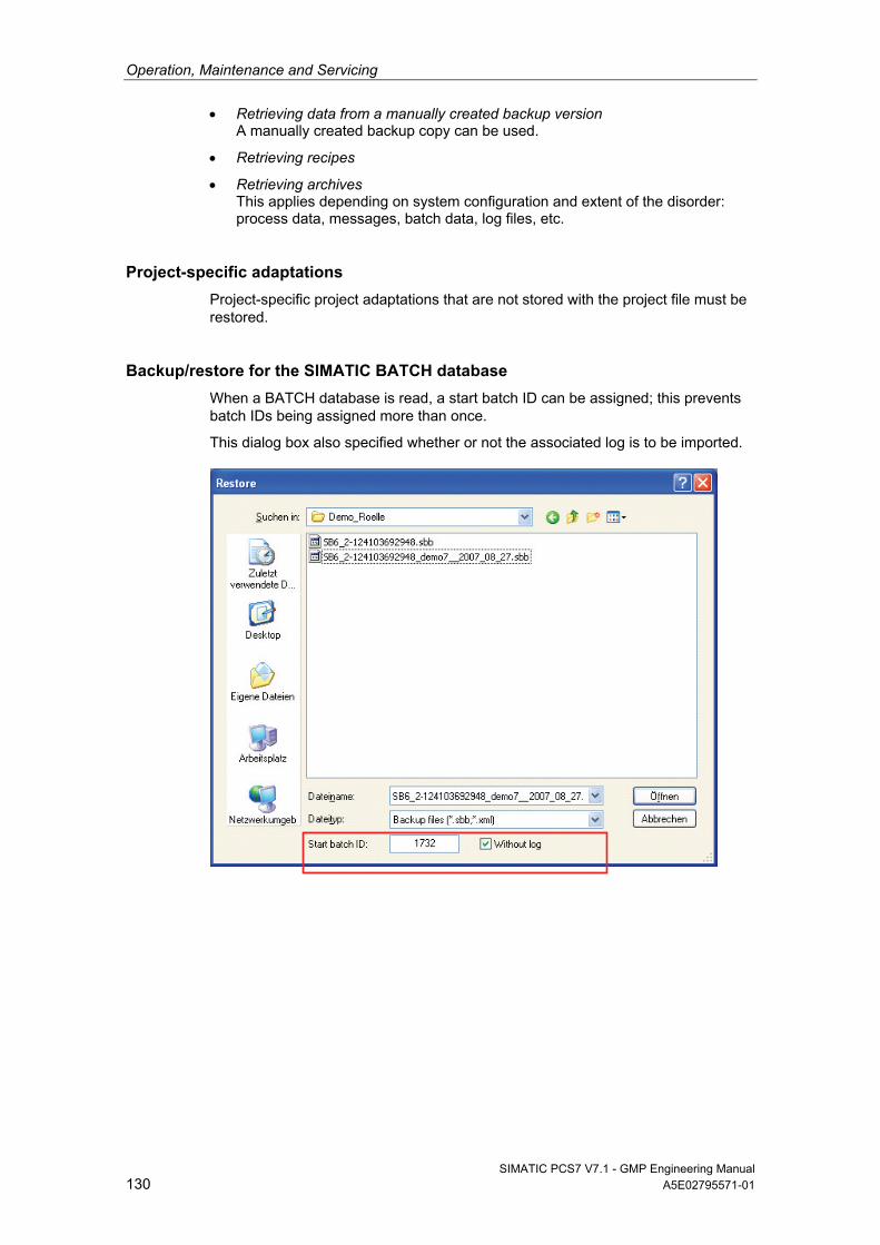
Operation, Maintenance and Servicing
SIMATIC PCS7 V7.1 - GMP Engineering Manual 130 A5E02795571-01
Retrieving data from a manually created backup version A manually created backup copy can be used.
Retrieving recipes
Retrieving archives This applies depending on system configuration and extent of the disorder: process data, messages, batch data, log files, etc.
Project-specific adaptations
Project-specific project adaptations that are not stored with the project file must be restored.
Backup/restore for the SIMATIC BATCH database
When a BATCH database is read, a start batch ID can be assigned; this prevents batch IDs being assigned more than once.
This dialog box also specified whether or not the associated log is to be imported.
System Updates and Migration
SIMATIC PCS7 V7.1 - GMP Engineering Manual A5E02795571-01 131
9 System Updates and Migration
9.1 Updates and Service Packs
It is essential that system software updates for a validated plant are agreed with the user. An update such as this represents a system change, which must be planned and executed in accordance with the applicable change procedure. Similar to the description in chapter 8.2 "Change Control during Operation", this roughly means the following steps:
Describe the planned change
Effect on functions / plant units / documentation inclusion of the system description of the new and modified functions in the readme file/release notes
Assess risks
Define the tests which need to be performed to obtain validated status, based on the risk assessment
Approve/reject the change (in accordance with defined responsibilities)
Update of the technical documentation
Reassuring availability of up-to-date data backups
Execute the change in accordance with manufacturer documentation (as the plant has been released for it)
Document the activities performed
Qualification: Perform and document the necessary tests
Creating new data backups, may contain new system image
In considering possible influences, the following may be relevant:
Modules / typicals / instances / blocks / alarm system in terms of function and display
Interfaces
Effects during download
System performance
Documentation (specifications)
Qualification tests to be repeated or performed for the first time
Note
The SIMATIC Customer Support provides support for software updates and project migration at http://support.automation.siemens.com.
System Updates and Migration
SIMATIC PCS7 V7.1 - GMP Engineering Manual 132 A5E02795571-01
See also
Product Support http://support.automation.siemens.com/DE/view/de/39980937
9.2 Migrating to PCS 7
Due to growing requirements and upcoming enhancements to existing systems, many plants must be modernized, or at least expanded in the next few years. For this reason, the issue of migration, which refers to the transition to a new genera-tion of products featuring updated technology, is becoming more and more important for a number of plant operators, particularly in terms of process control engineering.
Siemens offers optimized migration solutions for the transition to SIMATIC PCS 7. This means that both users of previous Siemens control systems and of third-party control systems can utilize the benefits of Totally Integrated Automation in their processes.
A customized migration strategy is designed, taking into account the necessary qualification measures and based on the relevant general conditions, such as the basis which is already installed and on which the migration is to take place, defined plant stoppages (usually as brief as possible), etc.
Index List
SIMATIC PCS7 V7.1 - GMP Engineering Manual A5E02795571-01 133
Index List
A Access protection........................ 16, 35, 42, 104 Alarm management......................................... 82 Annex 11......................................................... 11 Approval.......................................................... 13 Archiving ............................................. 19, 28, 96 Asset management ..................85, 110, 118, 126 Audit trail ....................................... 17, 18, 86, 87
Archiving ................................................... 103 PCS 7 OS ................................................... 89 SIMATIC BATCH ........................................ 90 StoragePlus .............................................. 104
Automation License Manager ....................... 115
B Backup........................................ 19, 95, 96, 127 Batch data....................................................... 99 Batch documentation ................................ 18, 81 Batch Report ........................................... 81, 105 Block icons...................................................... 69
C CAS ........................................................ 28, 100 Category
Hardware .................................................... 14 software ........................................ 14, 73, 112
CFC .................................................. 24, 60, 124 Change control........................................ 86, 128 Change procedure .......................................... 13 Condition monitoring ..................................... 127 Configuration management....................... 15, 59 Continuous Function Chart ............... 24, 60, 124
E Electronic records ..................................... 17, 96 Electronic signature .................................. 17, 92
PCS 7 ES.................................................... 95 PCS 7 OS ................................................... 94 SIMATIC BATCH ........................................ 92 SIMATIC Logon .......................................... 92
Engineering system ........................................ 24
F FDA 21 CFR Part 11........................... 11, 17, 86 Firewall ........................................................... 44 Foundation Fieldbus ....................................... 55
G GAMP5 ........................................................... 11
H Hardware category ..........................................14 Hardware specification ....................................21 Hotfix .............................................................131
I Image ................................................30, 95, 129 Import/Export Assistant .......................25, 60, 71 Industrial Ethernet ...........................................52 Information security ...................................23, 44 Installation .......................................................31 Installed software ..........................................114 ISA-88.01 ..................................................29, 77
L Library .......................................................24, 47 Life cycle model...............................................11 Lifebeat Monitoring..................................85, 102
M Maintenance..................................................126 Master data library...........................................47 Message class.................................................83 Migration........................................................132 Multiproject ......................................................46
O OPC.................................................................26 Open PCS 7 ..............................................26, 75 Operating system ............................................24 Operator system..............................................26
P Package unit....................................................58 Partition ...........................................................30 Password.........................................................16 Password policies............................................33 PCS 7 Add-ons................................................28 PCS 7 OS Web ...............................................74 Plant hierarchy ................................................50 Printer driver....................................................29 Process pictures..............................................73 Process tag type..............................................68 PROFIBUS......................................................52
R Recipe control strategy....................................76 Referenced OS station ....................................46
Index List
SIMATIC PCS7 V7.1 - GMP Engineering Manual 134 A5E02795571-01
Regulations / guidelines.................................. 11 Remote maintenance.................................... 128 Retrieving data.................................. 19, 87, 130 ROP library ..................................................... 27 Route Control............................................ 25, 82
S S7-PLCSIM..................................................... 25 Scalance S...................................................... 44 Scripts............................................................. 73 Security........................................................... 23 Sequential Function Chart .....24, 26, 50, 60, 124 Service pack ................................................. 131 SFC........................................24, 26, 50, 60, 124 SFC type......................................................... 68 SFC Visualization............................................ 26 SICLOCK ........................................................ 58 SIMATIC BATCH .......27, 41, 76, 79, 92, 99, 105 SIMATIC Logon ............................ 24, 35, 74, 92 SIMATIC NET ................................................. 51 SIMATIC PDM ................................................ 54 SIMATIC Route Control .................................. 25 SIMATIC Security Control ............................... 44 SIMATIC Version Cross Manager................... 25 Simulation ..................................................... 118 Software category ............................. 14, 73, 112 Software modules ........................................... 67 Software specification ..................................... 23 Software update............................................ 131 Specification.................................................... 21 StoragePlus ............................................ 28, 103 Supplier audit .................................................. 20 System recovery ........................................... 129
T Third-party components...................................20 Time synchronization.................................20, 57 Typicals .....................................................15, 67
U UPS...............................................................106 User ID ............................................................16 User management ...............................16, 24, 31 User permissions.............................................36
V Validation manual ............................................12 Verification.....................................................109
Application software ..................................117 Hardware...................................................110 Software ....................................................112 Software product .......................................114
Version Cross Manager.....................25, 88, 122 Version Trail ......................................25, 96, 120 Versioning .......................................................60 Virus scanner ..................................................29 Visualization ..................................................126 VPN.................................................................45 VXM...................................................25, 88, 122
W Web Client.......................................................27

A5E02795571D-01 GN: 65000 - SIMATIC PCS 7 Pharma
GMP Engineering Manual Edition 06/2010
Siemens AG
Industry SectorIndustry Automation VMM Pharma76181 KARLSRUHEGERMANY
SIMATIC PCS 7 V7.1Guidelines for Implementing
Automation Projectsin a GMP Environment
[email protected]/simatic-pcs7
SIM
ATI
C P
CS
7 V
7.1
06
/20
10
GM
P En
gin
eeri
ng
Man
ual
psimatic pcs 7
A5E02795571-01


![Simatic Getting Started PCS7[1]](https://static.fdocuments.us/doc/165x107/577c7ab41a28abe05495ef1d/simatic-getting-started-pcs71.jpg)