cn.sokkia.com · (f Micrometer knob C! Light reflector il Telescope clamp ~ Telescope fine adjust...
16
~.LIETZ DOUBLE CENTER THEODOLITE TM-20C INSTRUCTION MANUAL f~, ~. LI ETZ THE LIETZ COMPANY 1645 E. Del Arno Blvd. Carson, Ca. 90746. (213)537-0410
Transcript of cn.sokkia.com · (f Micrometer knob C! Light reflector il Telescope clamp ~ Telescope fine adjust...
~.LIETZDOUBLE CENTER THEODOLITE TM-20C
INSTRUCTIONMANUAL
f~,
~. LI ETZTHE LIETZ COMPANY
1645 E. Del Arno Blvd. Carson, Ca. 90746. (213)537-0410
n
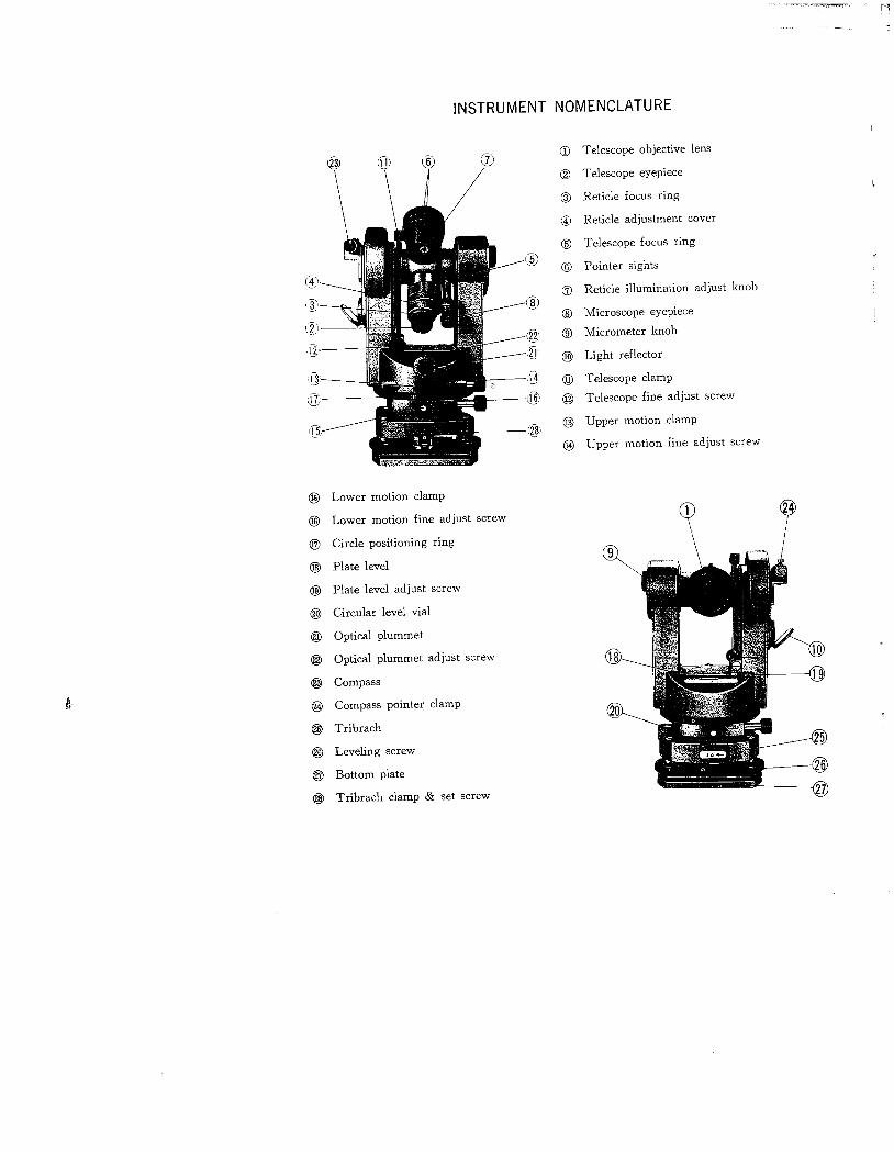
INSTRUMENT NOMENCLATURE
cr,
CDCD Telescope objective lens
CI Telescope eyepiece
~ Reticle focus ring
(1 Reticle adjustment cover
CI Telescope focus ring
CI Pointer sights
(j Reticle ilumination adjust knob
(S Microscope eyepiece
(f Micrometer knob
C! Light reflector
il Telescope clamp
~ Telescope fine adjust screw
Q? Upper motion clamp
(1 Upper motion fine adjust screw
il(~
iíl
i)
Ii:
in
l.
(j Lower motion clamp
Q§ Lower motion fine adjust screw
Q7 Circle positioning ring
Q§ Plate level
~ Plate level adjust screw
~ Circular level vial
(ê Optical plummet
~ Optical plummet adjust screw
~ Compass
~ Compass pointer clamp
CW Tribrach
~ Leveling screw
ê Bottom plate
rg Tribrach clamp & set screw
DOUBLE CENTER THEODOLITE TM-2üC
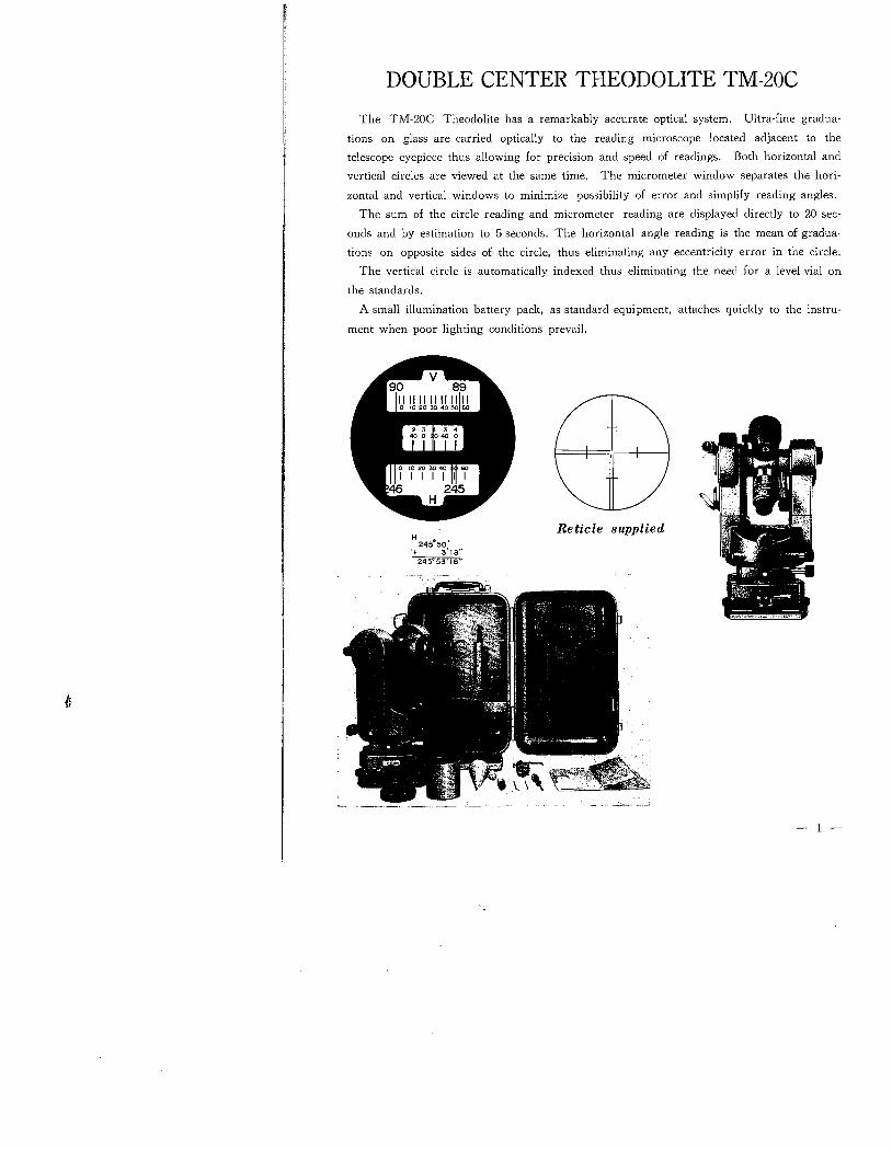
The TM-20C Theodolite has a remarkably accurate optical system. Ultra-fine gradua-tions on glass are carried optically to the reading microscope located adjacent to thetelescope eyepiece thus allowing for precision and speed of readings. Both horizontal andvertical circles are viewed at the same time. The micrometer window separates the hori-
zontal and vertical windows to minimize possibility of error and simplify reading angles.The sum of the circle reading and micrometer reading are displayed directly to 20 sec-
onds and by estimation to 5 seconds. The horizontal angle reading is the mean of gradua-
tions on opposite sides of the circle, thus eliminating any eccentricity error in the circle.The vertical circle is automatically indexed thus eliminating the need for a level vial on
the standards.
A small illumination battery pack, as standarcl equipment, attaches quickly to the instru-
ment when poor lighting conclitions prevaiL.~..1111-~
H 245050'
'+ 3'1 s"245°53'18"
Reticle supplied
)1'" '" . . .:1& . -'.." ~~I.I'_,.'.'..'.' ~1~W1"..".:." ..~.' .\~¡.'II" -
.. ,~'"Dl ~.' u ¡.
f(~' ~~.:¿"' f' '.-." . ..
i'_:!I_ "''':'
~
- ,.-' .-"-'=~~1..
- i -
-
t,
Telescope:6,9 inch (175mm), achromatic; internal focusing with straight cut rack andpinion. Erect image, reversible in both directions and balanced on axis. 28x mag-nification resolving to 3 seconds of arc. Minimum focus 41/. feet (1. 3m.). Objectiveaperture 1. 6 inch (40mm.), Field of view 1 degree 20 minutes (233 feet at 1000feet). Bronze telescope axis with cylindrical bearings. All lens surfaces coated
except first and last.Reticle:Glass, etched (type D), stadia ratio 1: 100. Constant is O. Stadia lines are shortto distinguish them from cross hairs.Horizontal Circle:3.15 inch (80mm.) diameter glass circle graduated to 1 degree. Micrometer scalereads direct to 20 seconds, with estimation to 5 seconds. Circle is numbered 0-360 degrees and can be positioned to any desired angle by means of an externalgraduated ring.
Vertical Circle:
2.75 inch (70mm,) diameter glass circle graduated to 1 degree. Micrometer scalereads direct to 20 seconds, with estimation to 5 seconds. Circle is numbered 0-360degrees with 0 at zenith, 90 degrees and 270 degrees at horizontal position.Automatic vertical circle indexing with range :: 5 minutes.Optical Reading System:Both horizontal and vertical circle readings are carried through a completely
enclosed system of prisms and lenses to a reading micrometer located adjacent tothe eyepiece of the telescope. Both circle readings and the micrometer scale areviewed simultaneously.Level Vials:Sensitivity of plate level vial 40 seconds per 2mm. Sensitivity of circular level vial10 minutes per 2mm.Optical Plummet:Crosshair target reticle located in the alidade so that it rotates with the instrument.Erect image-Focusing range 21" to 50 feet.Instrument Base:
Detachable tribrach with 5/sXll thread. Instrument is secured to tribrach by swivelclamp. Dust protectected leveling screws. Built-in circular level on tribrach.Centers:Hardened steel cylindrical centers with thrust bearings.Finish:Gray enameL.
Equipment:Hermetically sealed steel carrying case complete with plumb bob, trough compass,night ilumination battery pack, adjusting pin, dust cap, dust brush, sunshade,plastic rain hood.Weight:Instrument only-ll lbs. Case only-81/. lbs.Shipping weight-25 lbs.
- 2 -
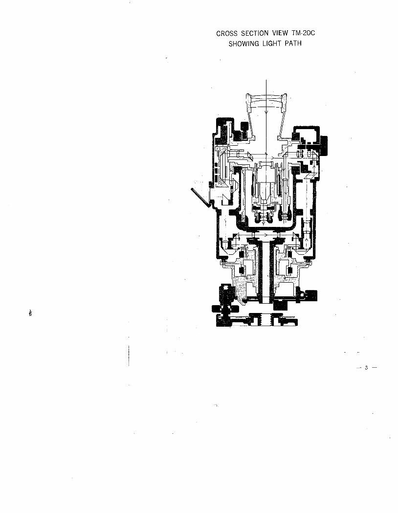
CROSS SECTION VIEW TM-20C
SHOWING LIGHT PATH
Ii
- 3 -
FEATURES OF THE TM-20 C
DIRECT READING MICROMETER SYSTEM
Horizontal circle, vertical and micro scales are within the same field of view. With themicroscale the horizontal and vertical circles can be read directly to 20 seconds and by
estimation to 5 seconds.
AUTOMATIC VERTICAL CIRCLE COMPENSATOR
With the automatic vertical circle compensator, vertical angles can be measured accurately
with the theodolite approximately horizontaL. The automatic compensator is the same as
that used in an automatic leveL. It automatically indexes the vertical circle by a pendulum
system to a true vertical axis (the direction of gravity) -thus providing good accuracy even
in locations where temperature changes rapidly or vibrations occur.
OPTICAL PLUMMET
With the optical plummet, the theodolite can be set up quickly regardless of wind condi
tions or vibrations-thereby greatly reducing the time required to plumb the instrument.
The optical plummet is located in the alidade so that it rotates with the instrument and
provides an erect image with a focussing range of 21" to 50 feet.DETACHABLE TRIBRACH
The TM-20 C Theodolite can be mounted and removed from its leveling base. Thus,
precise traverse surveys can made by use of an optical target which can be installed in the
tribrach. The tribrach wil also fit subtense bars as used for accurate measurement ofdistance.
NIGHT ILLUMINATION BATTERY PACK
The telescope reticles and micro-circle scales can be clearly seen and read by installing
the ilumination attachment in a position above the light reflector.HORIZONTAL CIRCLE POSITIONING RING
To facilitate the speed and ease of turning horizontal angles the TM-20 C Theodolite is
equipped with an external horizontal circle positioning ring. It is boldly marked at the
quadrant points, ie. 0 - 90° - 180° - 270°, and is knurled for ease of location and manipula-
tion while viewing the reading micrometer.
OPTIONAL ADDITIONAL ACCESSORIES AVAILABLE
l. CIRCULAR COMPASS
The circular compass is fitted with an easy reading prism and designed to fit into the
bracket which supports the standard accessory trough compass. It positions above thetelescope with sufficient room to allow transiting of the telescope.
DIAGONAL EYEPIECE PRISM
Measurement of vertical angles near zenith, and astronomical observations can be made
- 4-
made by replacing the regular eyepiece cap with this diagonal eyepiece. Prism delivers theimage at a 900 angle to the line of sight of the telescope.
RIGHT ANGLE (ZENITH) PRISM
Delivers image at a 900 angle to line of sight telescope. Replaces regular eyepiece cap.
Extra length enables full zenith cross hair observation. Set of two prisms (one for teles-cope eyepiece - one for microscope eyepiece). Complete with case.
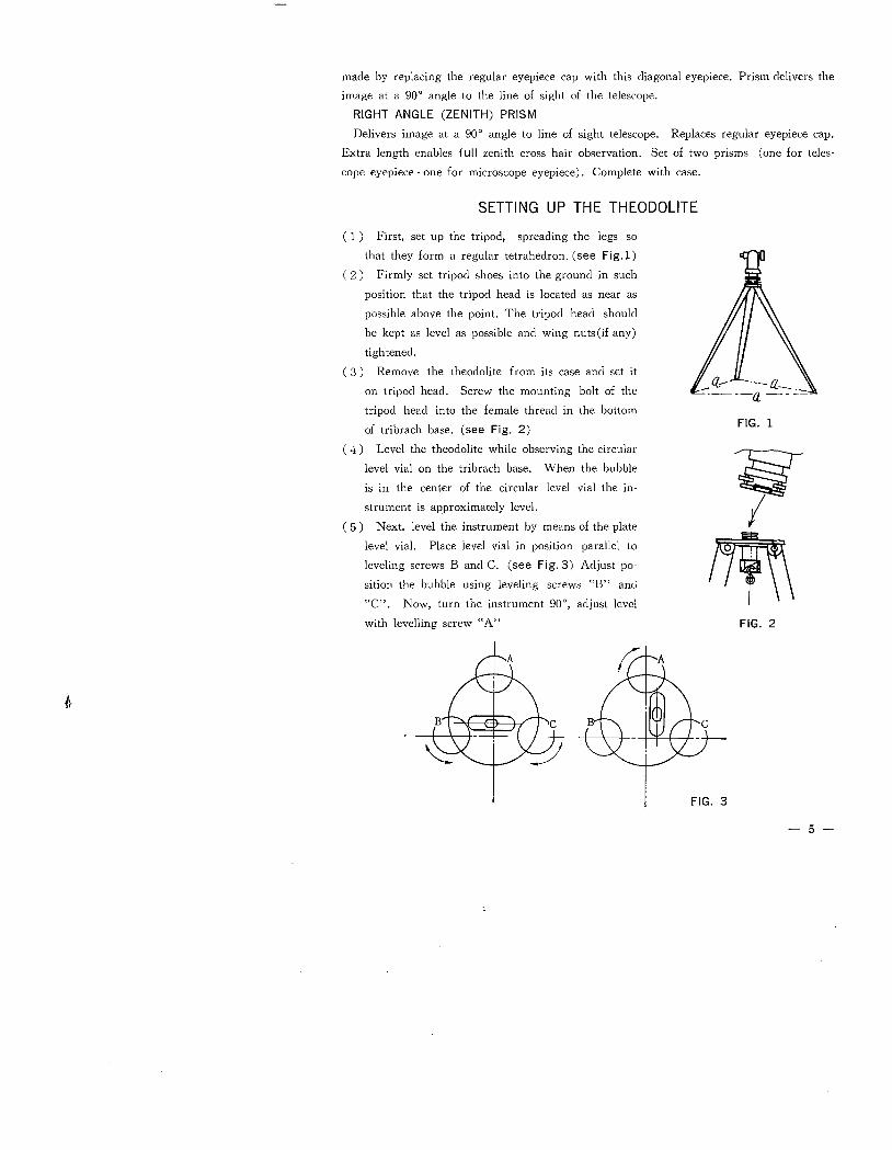
SETTING UP THE THEODOLITE
( 1) First, set up the tripod, spreading the legs so
that they form a regular tetrahedron. (see Fig.1)
( 2 ) Firmly set tripod shoes into the ground in such
position that the tripod head is located as near as
possible above the point. The tripod head should
be kept as level as possible and wing nuts(if any)
tightened.
( 3) Remove the theodolite from its case and set iton tripod head. Screw the mounting bolt of the
tripod head into the female thread II the bottom
of tribrach base. (see Fig. 2)
( ,,) Level the theodolite while observing the circular
level vial on the tribrach base. When the bubbleis in the center of the circular level vial the in-strument is approximately leveL.
( 5 ) Next, level the instrument by means of the plate
level viaL. Place level vial in position parallel toleveling screws Band C. (see Fig,3) Adjust po-sition the bubble using leveling screws "B" and"C". Now, turn the instrument 900, adjust levelwith levelling screw "A"
fr
FIG. 1
1fti
FIG. 2
FIG. 3
- 5-
( 6 ) Set the instrument on the point accurately by observing the point through the optical
plummet. By slightly loosening the mounting bolt. (Fig. 2) the instrument may be
shifted so to center the optical plummet reticle on to the point. It necessary, theleveling procedure in (5) may have to be repeated.
( 7) When the instrument is level and all vertical alignment is correct the optical reticlecenter will remain on the point throughout a 3600 rotation of the instrument.
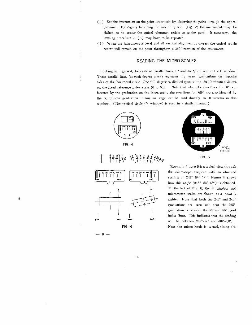
READING THE MICRO-SCALES
Looking at Figure 4, two sets of parallel lines, 00 and 3590, are seen in the H window.These parallel lines (at each degree mark) represent the actual graduations on opposite
sides of the horizontal circle. One full degree is divided epually into six 10 minute divisions
on the fixed reference index scale (0 to 60). Note that when the two lines for 00 arebisected by the graduation on the index scale, the two lines for 3590 are also bisected bythe 60 minute graduation. Thus an angle can be read directly to 10 minutes in thiswindow. (The vertical circle (V window) is read in a similar manner).
Ci'O "20 40 0a,'ii i'
t,
246 24~
- 6-
FIG. 4
.' (i3 3 4 ".0,'\ 40 0 40 0 I"'''O~'''
III --0
IA,
i~246 245
FIG. 6
FIG. 5
Shown in Figure 5 is a typical view through
the microscope eyepiece with an observed
reading of 2450- 53'- 18". Figure 6 showshow this angle (2450- 53'-18") is obtained.To the left of Fig, 6, the H window andmicrometer scales are shown as a point is
sighted. Note that both the 2450 and 2460
graduations are seen and that the 2450
graduation is between the 50' and 60' fixed
index lines. This indicates that the reading
wil be between 2450-50' and 2460-00'.
Next the micro-knob is turned, tilting the
parallel flat glass (see the right side of Fig,6). This moves the image of the graduationonly-and not the circle. Now the parallel 2450 lines are bisected by the 50 minute lineon the fixed index scale-and the additional increment reading of 3'-18/1 is read on the
micrometer scale for a final angle of 2450-53'-18/1.
+~ /~
',~ ~ //"0?\'/ I) \
"
l
24' 25' 50".~ /!i'~/j'' ~
.¡
l,
125'42'26"
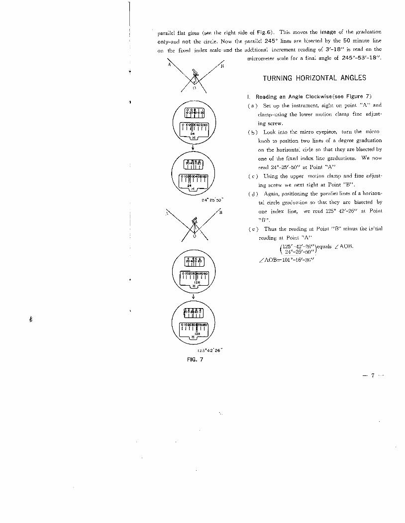
FIG. 7
TURNING HORIZONTAL ANGLES
i. Reading an Angle Clockwise (see Figure 7)
(a) Set up the instrument, sight on point "A" and
clamp-using the lower motion clamp fine adjust-
ing screw.
( b ) Look into the micro-eyepiece, turn the micro-knob to position two lines of a degree graduation
on the horizontal cirle so that they are bisected by
one of the fixed index line graduations. We now
read 240-25'-50/1 at Point "A"
( c) Using the upper motion clamp and fine adjust-
ing screw we next sight at Point "B".
( d) Again, positioning the parallel lines of a horizon-
tal circle graduation so that they are bisected by
one index line, we read 1250-42'-26/1 at Point
HB",
( e) Thus the reading at Point "B" minus the iD:,tiaJreading at Point "A"
(125°-42'-26/1)equals ¿ AOB.240 - 25'-50/1
¿AOB=101 0-16'-36/1
- 7 -
.,~ ,//8" ~ /"\D
/' (') \
~""'¥"~ '~H
:\. ./' 0 \
.¡
t,
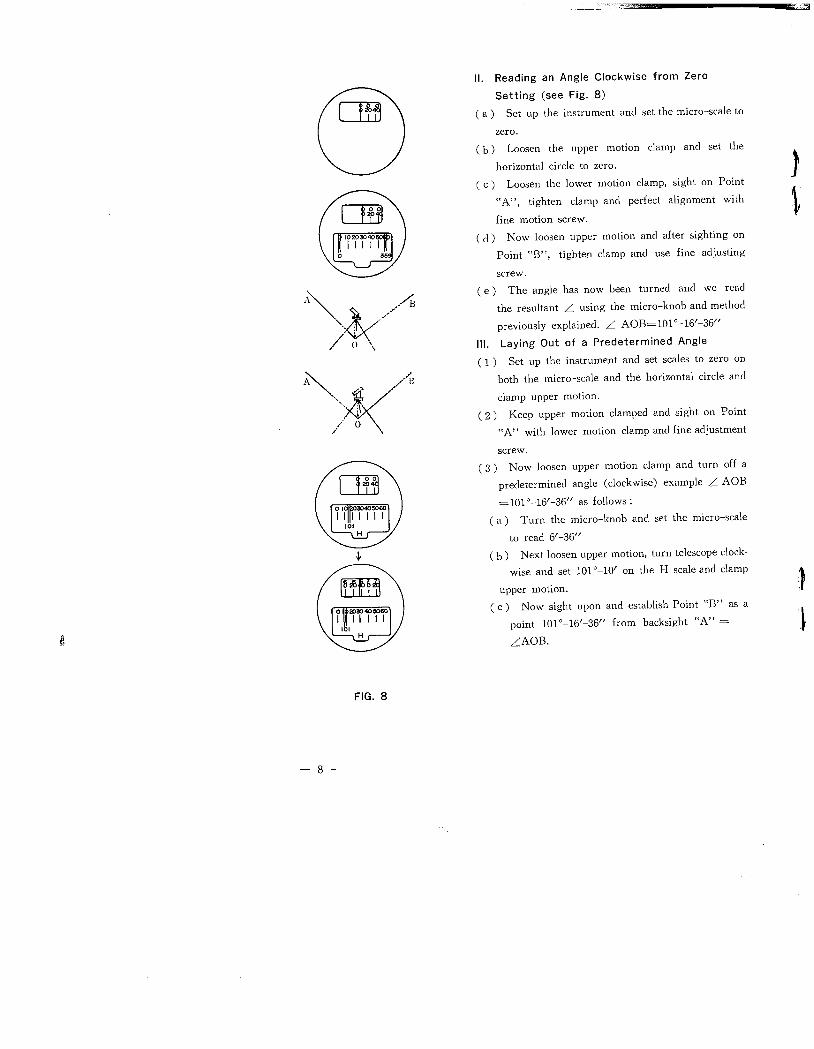
FIG. 8
- 8-
____.~.~=:O~,J '''
II. Reading an Angle Clockwise from Zero
Setting (see Fig. 8)
( a) Set up the instrument and set the micro-scale to
zero.
( b) Loosen the upper motion clamp and set the
horizontal circle to zero.
( c) Loosen the lower motion clamp, sight on Point
"A", tighten clamp and perfect alignment with
fine motion screw.
J
L
( d ) Now loosen upper motion and after sighting onPoint "B", tighten clamp and use fine adjustingscrew.
( e) The angle has now been turned and we read
the resultant L using the micro-knob and method
previously explained. L AOB=101 0_ 16/-36//
III. Laying Out of a Predetermined Angle
( 1) Set up the instrument and set scales to zero on
both the micro-scale and the horizontal circle and
clamp upper motion.
( 2) Keep upper motion clamped and sight on Point
"A" with lower motion clamp and fine adjustment
screw.
( 3) Now loosen upper motion clamp and turn off apredetermined angle (clockwise) example L AOB
=1010-16/-36// as follows:
( a) Turn the micro-knob and set the micro-scale
to read 6/-36//
( b) Next loosen upper motion, turn telescope clock-
wise and set 1010-10/ on the H scale and clamp
upper motion.
( c) Now sight upon and establish Point "B" as apoint 1010-16/-36// from backsight "A" =
LAOB.
)
:l
125°42'26"
)V
~
I~
i
l,
24°25'50"
FIG. 9
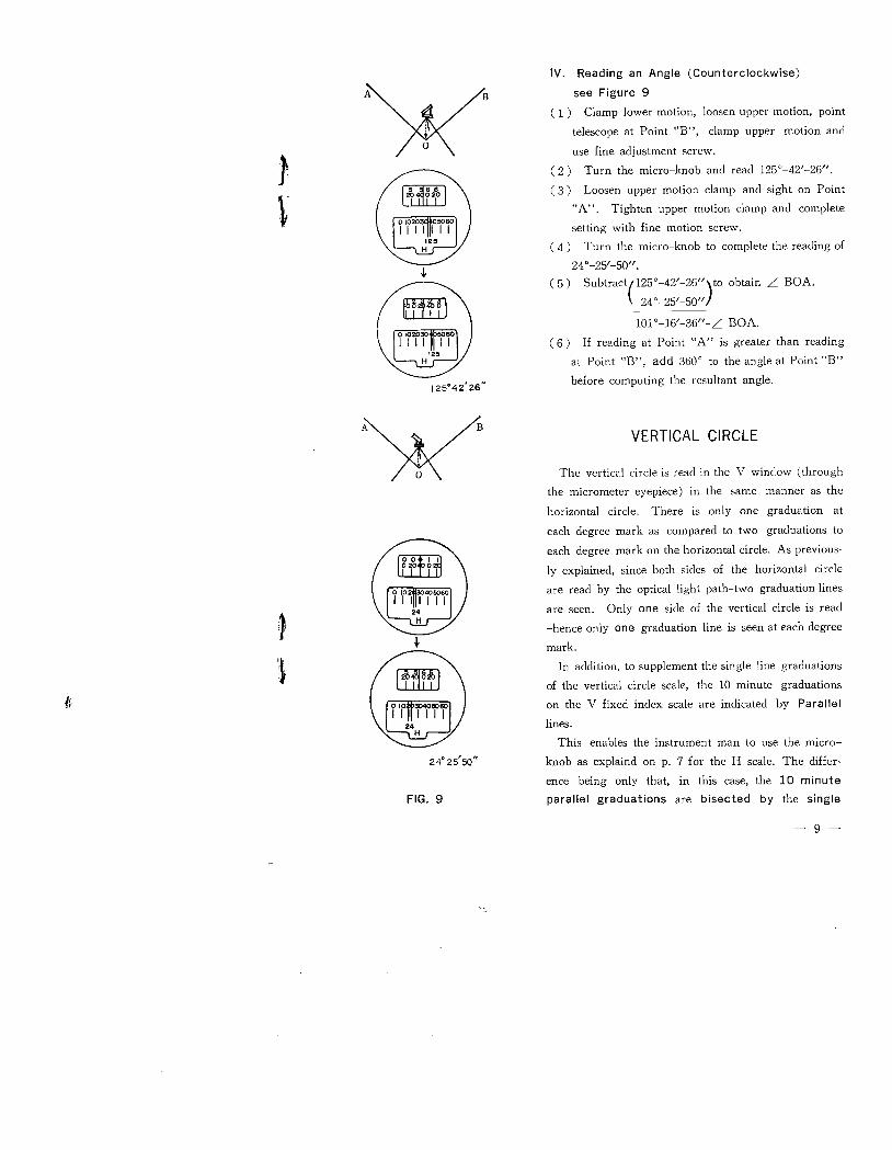
IV. Reading an Angle (Counterclockwise)
see Figure 9
( 1) Clamp lower motion, loosen upper motion, point
telescope at Point "B", clamp upper motion anduse fine adjustment screw.
Turn the micro-knob and read 1250-42/-26".
Loosen upper motion clamp and sight on Point"A". Tighten upper motion clamp and complete
setting with fine motion screw.Turn the micro-knob to complete the reading of
240-25/-50".Subtract(125°-42/-2611)to obtain ¿ BOA.
240-25/-5011
10l0-16/-3611-¿ BOA.
( 6) If reading at Point "A" is greater than reading
at Point "B", add 3600 to the angle at Point "B"
before computing the resultant angle.
VERTICAL CIRCLE
The vertical circle is read in the V window (throughthe micrometer eyepiece) in the same manner as the
horizontal circle. There is only one graduation ateach degree mark as compared to two graduations to
each degree mark on the horizontal circle. As previous-
ly explained, since both sides of the horizontal circle
are read by the optical light path-two graduation lines
are seen. Only one side of the vertical circle is read
-hence only one graduation line is seen at each degree
mark.
In addition, to supplement the single line graduations
of the vertical circle scale, the 10 minute graduationson the V fixed index scale are indicated by Parallellines.
This enables the instrument man to use the micro-
knob as explaind on p. 7 for the H scale. The differ'
ence being only that, in this case, the 10 minuteparallel graduations are bisected by the single
- 9-
degree graduation.
The vertical circle is installed in the instrument so as to read 900 when the telescope ISin a horizontal position and 2700 when it is in the plunged horizontal position.
The Model TM-20 C Theodolite is equipped with an automatic vertical circle compensa-tor which automatically indexes the circle to the direction of gravity despite temperaturechanges and vibration, The compensator has a range of ::5 minutes of arc, therefore theinstrument must be set level to within this range in order that the automatic indexingfeature wil function.
INSPECTION, CARE AND MINOR ADJUSTMENTS
Undue vibration, during transportation or operation, and extreme heat changes canadversely affect the accuracy of the instrument.
Before and during use, the instrument should be inspected periodically to assure that it
is in good working order-and minor adjustments should be made, if required, providingthose adjustments can be made in the field.
Please bear in mind that the TM-20 C Theodolite is a precise instrument and adjust-ments should be made II sequence. Thus, when acljusting, do not attempt to adjustcompletely in one step. It is recommended that you repeat adjustments and proceed in a
sequence which will provide a broad base of accuracy.
ADJUSTMENT PROCEDURES
I. Right angle alignment of the plate level vial compared to the vertical axis.n. Right angle alignment of the telescope reticle (vertical line) compared to the horizon-tal axis.
II. (A) Correct alignment of vertical reticle line
(B) Correct alignment of horizontal reticle lineIV. Coincidence of optical plummet axis with vertical axis
i. RIGHT ANGLE ALIGNMENT OF PLATE LEVEL VIAL TO VERTICAL AXIS
t,The level vial tube, being made of glass, can be affected by temprature fluctuation orshock. Be sure to inspect the plate level before using the instrument.
-10 -
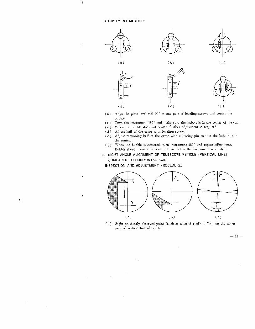
ADJUSTMENT METHOD:
~¡",i"~¡\1,1.,
-- ,-,I --
! ::¡;
I
( a) (b) ( c )
~l'-'-'
'-'1' '2_. .--
. \~J:Ii
( d ) ( e ) ( f)
( a ) Align the plate level vial 900 to one pair of leveling screws and center the
bubble.
( b ) Turn the instrument 1800 and make sure the bubble is in the center of the viaL.( c) When the bubble does not center, further adjustment is required.(d) Adjust half of the error with leveling screw.
( e) Adjust remaining half of the error with adjusting pin so that the bubble is inthe center.
( f) When the bubble is centered, turn instrument 1800 and repeat adjustment.Bubble should remain in center of vial when the instrument is rotated.
II. RIGHT ANGLE ALIGNMENT OF TELESCOPE RETICLE (VERTICAL LINE)
COMPARED TO HORIZONTAL AXIS
INSPECTION AND ADJUSTMENT PROCEDURE:
fr
(a) (b) ( c)
( a ) Sight on clearly observed point (such as edge of roof) to "A" on the upperpart of vertical line of reticle.
- 11-
. 7",'-::ry~~~ -.
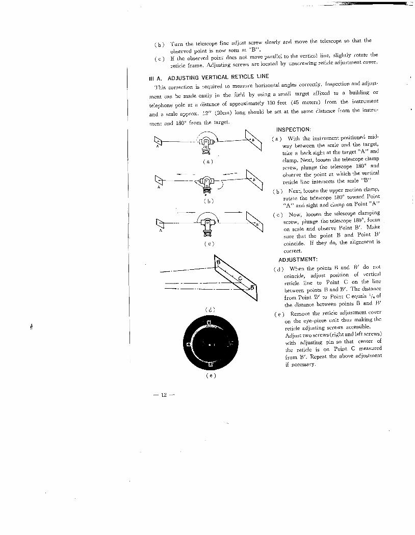
( b) Turn the telescope fine adjust screw slowly and move the telescope so that the
observed point is now seen at "B".( c) If the observed point does not move parallel to the vertical line, slightly rotate the
reticle frame. Adjusting screws are located by unscrewing reticle adjustment cover.
III A. ADJUSTING VERTICAL RETICLE LINE
This correction is required to measure horizontal angles correctly. Inspection and adjust-
ment can be made easily in the field by using a small target affixed to a building or
telephone pole at a distance of approximately 150 feet (45 meters) from the instrumentand a scale approx. 12" (30cm) long should be set at the same distance from the instru-
ment and 1800 from the target.
ti :~--.....i. : B..'.-
(a)
SJ
um~~'--''1~ ~.
(b)
t:A -v-~
( c )
-"-----"
(d)
t,
( e )
- 12-
INSPECTION:
( a) With the instrument positioned mid-
way between the scale and the target,take a back sight at the target "A" andclamp. Next, loosen the telescope clampscrew, plunge the telescope 1800 andobserve the point at which the verticalreticle line intersects the scale "B"
( b) Next, loosen the upper motion clamp,
rotate the telescope 1800 toward Point"A" and sight and clamp on Point "A"
( c) Now, loosen the telescope clamping
screw, plunge the telescope 1800, focuson scale and observe Point B/. Makesure that the point B and Point B'coincide. If they do, the alignment is
correct.
ADJUSTMENT:
( d) When the points Band B' do notcoincide, adjust position of verticalreticle line to Point C on the linebetween points Band B'. The distancefrom Point B' to Point C equals II. ofthe distance between points Band B'
( e) Remove the reticle adjustment coveron the eye-piece unit thus making the
reticle adjusting screws accessible.
Adjust two screws (right and left screws)with adjusting pin so that center of
the reticle is on Point C measured
from B/. Repeat the above adjustment
if necessary.
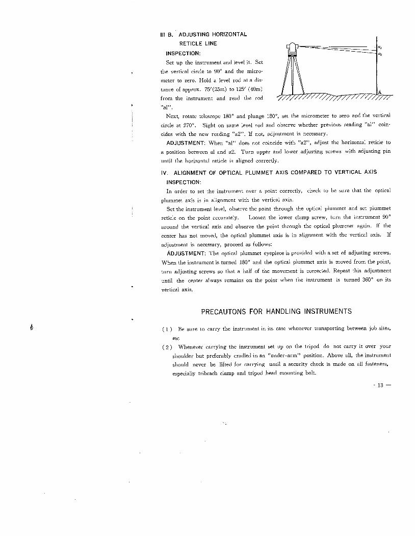
III B. ADJUSTING HORIZONTAL
RETICLE LINE
INSPECTION:
Set up the instrument and level it. Set
the vertical circle to 900 and the micro-
meter to zero. Hold a level rod at a dis-tance of approx. 75/(25m) to 125/ (40m)
from the instrument and read the rod
t~al" .
Next, rotate telescope 1800 and plunge 1800, set the micrometer to zero and the vertical
circle at 2700. Sight on same level rod and observe whether previous reading "al" coin-cides with the new reading "a2". If not, adjustment is necessary.
ADJUSTMENT: When "al" does not coincide with "a2", adjust the horizontal reticle to
a position between al and a2. Turn upper and lower adjusting screws with adjusting pin
until the horizontal reticle is aligned correctly.
IV. ALIGNMENT OF OPTICAL PLUMMET AXIS COMPARED TO VERTICAL AXIS
INSPECTION:
In order to set the instrument over a point correctly, check to be sure that the optical
plummet axis is in alignment with the vertical axis.
Set the instrument leveL, observe the point through the optical plummet and set plummet
reticle on the point accurately. Loosen the lower clamp screw, turn the instrument 900
around the vertical axis and observe the point through the optical plummet again. If thecenter has not moved, the optical plummet axis is in alignment with the vertical axis. Ifadjustment is necessary, proceed as follows:
ADJUSTMENT: The optical plummet eyepiece is provided with a set of adjusting screws.
When the instrument is turned 1800 and the optical plummet axis is moved from the point,
turn adjusting screws so that a half of the movement is corrected. Repeat this adjustment
until the center always remains on the point when the instrument is turned 3600 on its
vertical axis.
PRECAUTONS FOR HANDLING INSTRUMENTS
fr ( 1) Be sure to carry the instrument in its case whenever transporting between job sites,
etc
( 2 ) Whenever carrying the instrument set up on the tripod do not carry it over yourshoulder but preferably cradled in an "under-arm" position. Above all, the instrumentshould never be lifted for carrying until a security check is made on all fasteners,especially tribrach clamp and tripod head mounting bolt.
- 13-
( 3) When setting up the instrument be sure to spread the tripod legs suffciently so thatthe instrument is properly braced against possible falL.
( 4) Particular care should be taken not to grasp any part which may put the instrument
out of adjustment such as the telescope, level vial, etc.
( 5) When leaving the instrument set up for a long period of time, be sure to cover theinstrument with plastic instrument hood.
( 6) Avoid exposure of the instrument to rain, If the instrument is subjected to moisture,thoroughly wipe with a dry cloth before returning it to its case. Excessively clamp areas
may require frequent use of a drying agent material in storage case.
( 7) Upon completion of a survey, clean the instrument before retuning it to its case,Clean the lens carefully with a soft hair brush or lens tissue. When dust cannot beremoved by that method, use several drops of alcohol or ether on a piece of clean,lint free cloth and wipe the lens gently.
(8) When returning the instrument to its case, be sure to tighten all set screws lightly,Also make sure that the instrument sets into case easily-NEVER USE ANY FORCE.
Maintain a periodic inspection of the case latches for wear.
( 9 ) When transporting the instrument, it is recommended that it be carefully protectedfrom shock with proper cushioning,
Periodically inspect all accessories.
When the tripod is used for a long period of time, the leg shoes may be loosenedor wingnuts may be worn. Check them carefully before use.
(12) Be sure to keep the instrument in a place free from moisture and vibration. Alocker or shelf is recommended for storage. In no event should anything be put on
the case.
(10)
(11)
PERIODICAL INSPECTION AND MAINTENANCE
( 1) The theodolite is a precise instrument. Particular attention should be given to de-
terioration and hardening of lubricant. Make sure that all components operate smooth-
ly through periodic inspections; enlist the services of qualified instrument technicians
for a periodic maintenance program 'of cleaning, lubrication and adjustment.
Should there be any signs of foreign matter in the moving or threaded parts of the(2 )
t,
iu.;tcument-or any signs of moisture on the lens or prism inside the instrument,
contact your nearest qualified instrument repair facility immediately.
- 14-