Electronic Total Station SET3 - GLM · ing the telescope, it is automatically in the theodolite...
77
-
Upload
nguyenxuyen -
Category
Documents
-
view
218 -
download
0
Transcript of Electronic Total Station SET3 - GLM · ing the telescope, it is automatically in the theodolite...


CONTENTS
1 . PARTS OF THE INSTRUMENT . . . . . . . . . . . . . . . . . . . 1 2 . FEATURES . . . . . . . . . . . . . . . . . . . . . . . . . . . . . . . . . . . 4 3 . SPECIFICATIONS . . . . . . . . . . . . . . . . . . . . . . . . . . . . . . 5 4 . STANDARD EQUIPMENT . . . . . . . . . . . . . . . . . . . . . . . 8 5 . POWER SUPPLIES . . . . . . . . . . . . . . . . . . . . . . . . . . . . . 9
. . . . . . . . 6 . REFLECTING PRISMS AND ACCESSORIES 11 7 . DISPLAY SYMBOLS . . . . . . . . . . . . . . . . . . . . . . . . . . . . 13 8 . KEY FUNCTIONS . . . . . . . . . . . . . . . . . . . . . . . . . . . . . . 14 9 . INTERNAL SWITCHES . . . . . . . . . . . . . . . . . . . . . . . . . . 17
10 . OPERATION . . . . . . . . . . . . . . . . . . . . . . . . . . . . . . . . . . 18 10.1 PREPARATION FOR ANGLE MEASUREMENT . . 18
. . . . . . . 10.1.1 Battery. BDC18: Mounting and check 18 . . . . . . . . . . . . . 10.1.2 Compensation of zenith angle 19
10.1.3 Centring the SET3 by adjusting tripod leg length . . . . . . . . . . . . . . . . . . . . . . . . . . . . . . . . 20
10.1.4 Focussing . . . . . . . . . . . . . . . . . . . . . . . . . . . . . 20 10.2 ANGLE MEASUREMENT . . . . . . . . . . . . . . . . . . . . 21
. . . . . . . . 10.2.1 Automatically indexing vertical circle 21 10.2.2 Angle measurement . . . . . . . . . . . . . . . . . . . . . . 22 10.2.3 Setting the horizontal circle to a required
value i.e. reference target value . . . . . . . . . . . . 23 10.2.4 Repetition of angles . . . . . . . . . . . . . . . . . . . . . 24
10.3 PREPARATION FOR DISTANCE MEASUREMENT . . . . . . . . . . . . . . . . . . . . . . . . . . . 26
. . . . . . . . . . . . . . . . . 10.3.1 Prism constant correction 26 . . . . . . . . . . . . . . . . . . . 10.3.2 Atmospheric correction 27
. . . . . 10.3.3 Earth-curvature and refraction correction 29 . . . . . . . . . . . . . . . . . . . . . . . . . . 10.3.4 Prism sighting 30 . . . . . . . . . . . . . . . . . . . . . . . . . 10.3.5 Mode selection 31
. . . . . . . . . . . . . . . . . 10.4 DISTANCE MEASUREMENT 32 . . . . . . . . . . . 10.4.1 Angle and distance measurement 32
. . . . . . . . . . . . . . . 10.4.2 Measurement of coordinates 35 . . . . . . . . . . . . 10.4.3 Remote elevation measurement 37
10.4.4 Measurement of horizontat distance and height difference between two or more target points . . . . . . . . . . . . . . . . . . . . . . . . . . . 39
10.5 SETTING OUT (STAKE-OUT) MEASUREMENT . . 41 10.5.1 Horizontal angle setting out (stake-out)
measurement . . . . . . . . . . . . . . . . . . . . . . . . . . . 41 . . . . . . . . . . 10.5.2 Distance setting out measurement 43
11 . SELF DIAGNOSIS . . . . . . . . . . . . . . . . . . . . . . . . . . . . . 45 12 . OPTIONAL ACCESSORIES . . . . . . . . . . . . . . . . . . . . . . 47
. . . . . . . . . . . . . . . . . 12.1 DIAGONAL EYEPIECE DE18 47

12.2 ELECTRONIC FIELD BOOK SDR2 . . . . . . . . . . . . 47 12.3 INTERFACE I F I A FOR THE HP41CV . . . . . . . . . 48
13 . CHECKS AND ADJUSTMENTS . . . . . . . . . . . . . . . . . . . 49 13.1 ANGLE MEASURING FUNCTION . . . . . . . . . . . . . 49
. . . . . . . . . . . . . . . . . . . . . . . . . . . . . 13.1 . 1 Plate level 49 13.1.2 Circular level . . . . . . . . . . . . . . . . . . . . . . . . . . . 51 13.1.3 Index error of the t i l t angle sensor . . . . . . . . . 51
. . . . . . . . . . . . . . . . . . . . . . . . . . . . . . . 13.1.4 Reticle 53 13.1.5 Perpendicularity of the reticle to the
. . . . . . . . . . . . . . . . . . . . . . . . . horizontal axis 56 13.1.6 Coincidence of the distance measuring axis
with the reticle . . . . . . . . . . . . . . . . . . . . . . . . . 57 13.1.7 Optical plummet . . . . . . . . . . . . . . . . . . . . . . . . 58
13.2 DISTANCE MEASURING FUNCTION . . . . . . . . . . 59 13.2.1 Check flow chart . . . . . . . . . . . . . . . . . . . . . . . 59
. . . . . . . . . . . . . . . . 13.2.2 Additive distance constant 60 14 . FOR ANGLE MEASUREMENT OF THE HIGHEST
. . . . . . . . . . . . . . . . . . . . . . . . . . . . . . . . . . ACCURACY 62 14.1 LEVELLING BY REFERRING TO THE
DISPLAY . . . . . . . . . . . . . . . . . . . . . . . . . . . . . . . . . 62 14.2 MANUALLY INDEXING VERTICAL CIRCLE
. . . . . . . . . . . . . . . . . . . . . . . . . . . . . . . . BY V1, V2 65 15 . FOR DISTANCE MEASUREMENT OF THE
. . . . . . . . . . . . . . . . . . . . . . . . . . HIGHEST ACCURACY 67 15.1 ACCURACY OF MEASUREMENT OF
. . . . . . . . . . . . . . . . ATMOSPHERIC CONDITIONS 67 15.2 TO OBTAIN THE ATMOSPHERIC PRESSURE . . . 67
16 . PRECAUTIONS AND MAINTENANCE . . . . . . . . . . . . . 69 . . . . . . . . . . . . . . . . . . . . . . . . . . . . 16.1 PRECAUTIONS 69
16.2 MAINTENANCE . . . . . . . . . . . . . . . . . . . . . . . . . . . . 70 17 . ATMOSPHERIC CORRECTION CHARTS . . . . . . . . . . . 71
. . . . . . . . . . . . . . . . . . . . . . . . . . . . . . . . . . . . . . . 18 . INDEX 73
I Tribrach clamp I locking screw
IMPORTANT When the new SET3 i s shipped. the tribrach clamp is fixed with a screw . Loosen i t and leave it loose .

1. PARTS OF THE INSTRUMENT
Fig. 1.1
0 Handle @ Handle securing screw @ Instrument height mark 0 Internal switch cover 43 Display @ Lower clamp @ Lower fine motion screw
Tribrach clamp @ Circular level adjusting
screw
@ Circular level Q) Base plate @ Levelling foot screw @ Tribrach (D Horizontal circle posit
ring @ Keyboard @ Prism constant switch (D Objective lens
ioning
cover

Fig. 1.2
@ Tubular compass slot @ Battery, BDC18 @ Sensor index adjustment
cover Optical plummet focussing ring
@ Optical plummet eyepiece @ Power switch @ Horizontal clamp
@ Hor~zontal f ~ n e motlon screw
@ Data output connector @ External power source
connector @ Plate level @ Plate level adjusting screw @ Vert~cal clamp @ Vert~cal f ~ n e motlon screw

Fig. 1.3
Peep slght @ Measureltrack swltch @ Telescope reticle adjustment @ ppm sw~tch
cover @ Return signal lamp @ Telescope plung~ng knob @ Telescope eyepiece @ Return s~gnal audio switch 0 Telescope focuss~ng ring

2. FEATURES
Horizontal angle, zenith angle, slope distance, horizontal distance, height difference, N- and E-coordinates are displayed by key operation. Horizontal distance between two prism points and remote measurement of objects above and below a prism point are automatically calculated. A setting-out (stake-out) function for angles or distances is provided. Self-diagnostic function. If, for any reason, the SET3 is not functioning correctly during use, an error code is displayed. Angle resolution can.be set to l " (0.2mgon) or 5" ( l mgon). The ti l t angle of the vertical axis can be measured by the internal sensor and displayed. By referring to the display, the SET3 can be levelled. The zenith angle is automatically com- pensated by the ti l t sensor and the compensated angle dis- played. Horizontal circle can be set to zero in any direction. The SET3automatically switches off 30 minutes after the last operation to save battery power. An RS-232C data-output connector is standard. Two way communication with a field or office computer is available.

3. SPECIFICATIONS
Distance measurement Range: (When using Sokkisha standard reflecting prisms)
Average conditions: (Slight haze, visibility about 20 km, sunny periods, weak scintillation) l -prism 1,900 m 3-prisms 2,600 m
Good conditions: (No haze, visibility about 40km, overcast, no scintillation) l -prism 2,200 m 3-prisms 3,000 m
Standard deviation k ( 5 m m -I-3ppm.D) Display: LCD 8-digit Four display windows,
two on each face Maximum slope distance 9,999.999 m
Minimum display: MEAS. 1 mm TRACK. lOmm
/ MEAS. 1 TRACK. 1 Measuring time:
Slope distance
Mode
Horizontal distance
Coordinates
Remote elevation
Atmospheric correction: -99 ppm to + l99 ppm (I ppm per step)
Prism constant correction: -99 mm to +59 mm (1 mm per step)
Earth-curvature and refraction correction: Selectable ON/OFF
Audio target aquisition: Selectable ON/OFF Signal source: Infrared LED Light intensity control: Automatic
/ 7 s + every 1 s
1 s + every 0.5 s
distance between two points
8 + every 5 S 8 S + every 1

Angle measurement Telescope
Length: Aperture: Magnification: Resolving power: I mage: Field of view: Minimum focus:
Horizontal circle Type: Minimum display:
Vertical circle Type: Minimum display:
Accuracy
Automatic compensator Type: Minimum display: Range of compensation:
Display Range:
Measuring mode Horizontal angle: Vertical angle:
Measuring time:
177 mm 45 mm, EDM: 50 mm 30 X
3" Erect 1°30' (26 m/l,000 m) 1.3m
l ncremental l " (0.2 mgon)
Incremental with 0 index l" (0.2 mgon) Standard deviation of mean of measurement taken in positions I and I1 (DIN 18723) 3" (0.9 mgon) 3" (0.9 mgon)
Selectable ONIOFF Liquid 1" (0.2 mgon) + 3'
Right/Left/Repetition of angles Zenith O0 (Ogon) or Horizontal 0" (Ogon) or Horizontal 0°rt900 (0 gonk l 00 gon) Less than 0.5s

Sensitivity of levels Plate level: Circular level:
Optical plummet Image: Magnification: Minimum focus:
Data input/output:
Self-diagnostic function: Power saving cut off: Operating temperature: Power source:
Working duration:
Charging time:
Instrument height: Size (without handle): Weight:
Erect 3 X
0.1 m
Asynchronous serial, RS-232C compatible Provided 30 minutes after operation -20°C to +50°C Ni-Cd battery, BDC18 (6V) About 600 measurement at 25OC, distance and angle measurement; 13 hours at 25"C, angle measure- ment only. (About 4,000 measurements, dis- tance and angle measurement; 90 hours at 2S0C, angle measurement only, with optional battery BDCl2.) 12 to 15 hours, standard charger CDCI 1 ICDC1 l D (depending on in- put voltages) (1 hour, optional charger CDCI 2A, CDC13, CDC15) 236 mm 168 (W)x177 (D )x330 (H ) mm 7.6 kg (wlinternal battery)

4 . STANDARD EQUIPMENT
SET3 main unit . . . . . . . . 1 Internal battery. BDC18 . . 2 Battery charger.
CDCII ICDCIID . . . . . . 1 Battery charging adaptor.
EDCl l . . . . . . . . . . . . . . 1 Tubular compass. CP7
(accuracy: + 1') . . . . . . . 1 Lens cap . . . . . . . . . . . . . . 1 Lens hood . . . . . . . . . . . . . 1 Vinyl cover . . . . . . . . . . . . 1
Fig . 4.1
Plumb bob . . . . . . . . . . . . 1 Tool pouch . . . . . . . . . . . . 1 Screwdriver . . . . . . . . . . . . 1 Lens brush . . . . . . . . . . . . 1 Adjusting pin . . . . . . . . . . 2 Cleaning cloth . . . . . . . . . . 1 Atmospheric correction
chart . . . . . . . . . . . . . . . . 1 Operator's manual . . . . . . . 1 Carrying case. SC46 . . . . . 1

5. POWER SUPPLIES
The SET3 can be operated with the following combinations: 12 t o 15 hours
* Standard set. ( l00 t o 120V AC) Optional accessories are not marked with an asterisk. (220 t o 240V AC)
l hour quick charger CDC12A (120V AC)
1 hour cigar lighter charger CDC13 (12V DC)
1 hour quick ;;;g;;
(100,120, 220,240V AC)
AC power adaptor
External battery E%@ 15 hours charger CDC14A (120V AC)
Cable t o cigar lighter EDC4
" '8 Cable t o car External battery battery converter
Fig. 5.1 EDC14 EDC5
Use the SET3 only with the combinations shown here.
Note: When using the SET3 with external power supplies, i t is recommended that for the most accurate angle measure- ments, the BDC18 battery be left in place to balance the weight on the axes.

Battery charging precautions
To charge the battery, use only the recommended charger.
1) Charge the battery a t least once a month if i t i s not used for a long time.
2) Charge the battery a t a temperature between 10°C and 40°C.
3) Before using EDC2 or CDCI 5, set the voltage selector to the proper voltage.
4) EDC14 has a breaker switch. Normally the red mark appears on the breaker. I f not, set the red mark in place.
5) When using a car battery, make sure that the polarity is correct.
6) Make sure that the cigar lighter has 12V output and that the negative terminal is grounded.
7) When charging the battery, first connect it to the battery charger and then connect the charger to the power supply. Check that the battery charger light i s on. If not switch power supply off and on again until the light comes on.
8) The battery charger may become warm while charging. This i s normal.
9) Do not charge the battery for any longer than specified.
10) Store the battery in a place where the temperature is between 0°C and 40°C.
11) Battery operating life i s shortened at extreme temperatures.

6. REFLECTING PRISMS A N D ACCESSORIES
All Sokkisha reflecting prisms and their accessories have stan- dardized screws (518" X 11 thread) for easy compatibility.
Fig. 6.1
* A l l the equipment described
APS12P APSl lP above i s optional.
* I : See 10.3.1 Prism constant correction. "2: Fluorescent paint finishing allows clearer sighting in adverse observing
conditions. - 11 -

Precautions 1 ) Carefully face the reflecting prism towards the instrument;
sight the target centre accurately. 2) To use the triple prism assembly AP31 or AP32 as a single
prism (e.g. for short distances), mount the single prism APOI in the centre hole of the triple prism holder.
3) Check that "236" (the height of the SET3) is displayed in the window of the instrument height adaptor AP41. The height of the AP41 can be adjusted as follows: @ Loosen the two fixing screws. @ Turn the centre part counterclockwise to unlock it. @l Move it up or down until "236" appears in the window. @ Turn the centre part clockwise to re-lock it. @ Tighten the fixing screws.
Fig. 6.2 Fig. 6.3
Note: SET3 instruments with a serial number less than 79301 have a height of 233 mm.
4) Use the plate level on the AP41 to adjust the tribrach circular level as in 13.1.2.
5) Check the optical plummet of the AP41 as in 13.1.7. After all checks and adjustments have been completed, make sure that the AP41 optical plummet sights the same point as the optical plummet of the SET3.

7. DISPLAY SYMBOLS
4 Slope distance
,
d Hor i zon ta l distance
d l Height d i f fe rence
ILL+ N-coord inate
g+ E-coord inate
I + Compensated angle -- -I, T i l t angle
Ho r i zon ta l H I' angle r i gh t
H , Hor i zon ta l
t H 4 I b b S.0 Z e n i t h angle V between t w o po ln t s
e
I angle le f t
Ho r i zon ta l angle . H "' repet i t ion i I
Distance, angle o r er ror code
Fig. 7.1

8. KEY FUNCTIONS
SET3 has three measurement modes. When it is switched on and the vertical circle is indexed by rotat- ing the telescope, it is automatically in the theodolite mode.
Fig. 8.1
Theodolite mode
Angle measurement.
SET3 accepts a, m. 1.0. m, m or B keys.
Basic mode
Prism sighting, data entry and recall.
SET3 accepts all keys except a. m, m, 6/) or B keys.
EDM + Theodolite mode
Angle and distance measurement.
SET3 accepts or keys.

Fig. 8.2
8 e Select theodolite mode.
* Stop data entry halfway before m has been pressed @ Stop measurement and transfer to basic mode.
m @ Set horizontal angle to zero. To confirm zero setting, press m. When using the "Measuring distance between 2 poinrs" function, set the starting point to the values of the last measured point.
m * Change the sign of data before entry. Recall data from memory.
@ Enter "7". m Measure slope dis7ance.
Enter "8". e Measure horizontal distance.
@ Enter "9". @ Measure height difference.
CIear entry. Select horizontal angle to left, right or by repetition (accumulation).
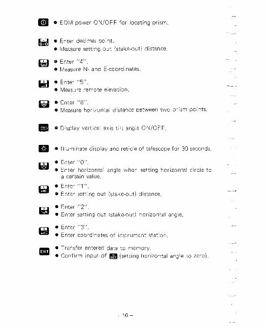
m 0 EDM power ON/OFF for locating prism.
@ Enter decimal point. e Measure setting out (stake-out) distance.
@J e Enter "4". e Measure N- and E-coordinates.
@ Enter "5". Measure remote elevation
e Enter "6". 0 Measure horizontal distance between two prism points.
6-3 @ Display vertical axis t i l t angle ON/OFF
m 0 Illuminate display and reticle of telescope for 30 seconds.
Enter "0". Q Enter horizontal angle when setting horizontal circle to
a certain value.
0 Enter "1". Enter setting out (stake-out) distance.
Enter "2". 0 Enter setting out (stake-out) horizontal angle,
Q Enter "3". e Enter coordinates of instrument station.
Transfer entered data to memory. Confirm input of (setting horizontal angle to zero).

9. INTERNAL SWITCHES
Switches are located under internal switch cover I"' z L" m TILT
0 m FEET
m 0"i90" r
Fig. 9.1
I Switch I Function I ON Angle resolution 5"/1 mgon 1 1 * OFF Anoe resolution 1 "/0.2 rnaon
ON Manually index vertical circle by V,, V, 1 6 1 *OFF Automatically index vertical circle by transitting telescope
ON Vertical circle compensator off *OFF Vertical circle compensator on
ON Display distance in feet 'OFF Display distance in meters
ON Distance corrected for earth-curvature and refraction l l * OFF Distance not corrected for earth-curvature and refraction
ON Display vertical angle w i th 0' (Ogon) horizontal 1 2 1 190° i100gon i * O F F Vertical anale display controlled by switch 1
ON Display vertical angle with O0 (Ogon) horizontal
* OFF Displav zenith anale
(The asterisk indicates the position of each switch at the t ime of shipping from factory.) Before changing switch settings, turn power switch OFF.

10. OPERATION
10.1 PREPARATION FOR ANGLE MEASUREMENT
10.1.1 Battery, BDC18: Mounting and check 1 ) Confirm that the power switch @ is OFF. 2) Mount the battery BDC18 in the SET3.
Hold the left standard when inserting the battery. Push it until a click is heard to indicate correct location. Confirm that the battery is fixed securely.
Release button
Guide
To remove the battery, turn the power switch OFF and push down the release button of the battery.
3) Two short audio signals are heard when the power is switched ON. The display shown in @ and then @ indicate the instru- ment is in normal condition.
. . I
I second
Fig. 10.2

If the battery voltage is too low, the display will appear as shown below. Set the power switch OFF and replace the battery with a charged one, or charge the battery.
Battery voltage is t o o 1 0 ~ .
Fig. 10.3
10.1.2 Compensation of zenith angle
1 ) Remove the switch cover a. 2) To use zenith angle with compensation, set switch 5 to OFF
with a screw driver. (The factory setting is OFF.) 3) Replace the cover.
h
(0
z "= 0 .t
0
N Compensation select
.m3 O N - Without compensation
"Cmn O F F -With c o m ~ e n s a t i o n
This mark appears when the internal switch 5 is set t o 0 F F. When th is mark appears, the angle is
M compensated automatical ly.
switch
n9-1 r~h n"
Fig. 10.4
The internal t i l t sensor has a range of +3' and a resolution of 1 ". Read the automatically compensated zenith angle when the display is steady. When the display is not steady due to vibration or strong wind, set switch 5 to ON to use the SET3 without compensation.

10.1.3 Centring the SET3 by adjusting tripod leg length 1 ) Make sure that:
a. The tripod head is approximately level. b. The tripod shoes are firmly fixed in the ground.
2) Set the SET3 on the tripod head. Tighten the centring screw. 3) Focus on the surveying point:
a. Turn the optical plummet eyepiece @ to focus on the reticle.
b. Turn the optical plummet focussing ring @ to focus on the surveying point.
4) Turn the levelling foot screws @ to centre the surveying point in the reticle.
5) Observe the off-centre direction of the bubble in the circular level (D. Shorten the leg nearest that direction, or extend the leg farthest from that direction. Generally, two legs must be adjusted to centre the bubble.
6) When centring of the circular level is completed, turn the levelling screws to centre the plate level @ bubble.
7) Look through the optical plummet again. If the surveying point is off-centre, loosen the centring screw to centre the surveying point on the reticle. Tighten the centring screw.
8) Repeat 6), 7) if the plate level bubble is off-centre.
10.1.4 Focussing 1 ) Looking through the telescope, turn the eyepiece fully clock-
wise, then anticlockwise until just before the reticle image becomes blurred. In this way, frequent refocussing can be dispensed with, since your eye is focussed at infinity.
2) Loosen the vertical @ and horizontal clamp @. Bring the target into the field of view with the peep sight @. Tighten both clamps.
3) Turn the focussing ring @ and focus on the target. Sight the target with the vertical @ and horizontal fine motion screws @. Focus on the target until there is no parallax between the target and the reticle.

Parallax: Relative displacement of target image in respect to the reticle when observer's head is moved slightly before the eyepiece. If sighting i s carried out before parallax is eliminated, this will introduce errors in reading and will impair your observations.
10.2 ANGLE MEASUREMENT
r Make sure that: a. The SET3 i s set up correctly over the surveying point. b. Battery voltage is adequate.
10.2.1 Automatically indexing vertical circle
1) Turn the power switch @ ON. Make sure that the display appears as shown below.
400 gon
Fig. 10.5
2) Loosen the vertical clamp a, and use the telescope plunging knob @ to rotate the telescope completely. (Indexing occurs when the objective lens crosses the horizontal plane in position V1 .) When the vertical circle is indexed, an audio signal is given and the display appears as below.
400 gon
* I . . . I I n * . 1 8-8 ,-, 4-t S-, 8-8 L1 ,-l !-l ,-l 8-1
$7 ,-l 6 7 #-l ,l ,-l t-l 1-1 6-1 #-l
Fig. 10.6

Angle measurement can now begin. Note: When the power switch is turned off for any reason,
the vertical index is lost. When the power switch is turned back on, the vertical index must be redeter- mined.
10.2.2 Angle measurement
Before this procedure, index the vertical circle. l l ) Select theodolite mode by pressing m. 2) Select the horizontal angle right or left with according to
measuring method.
Display
H #) ........ Horizontal angle
H qfl ............ Horizontal angle left
i H I)) ..... Horizontal angle repeti t ion
Fig. 10.7
When is pressed, the display changes alternately as shown in Fig. 10.7.
3) Sight the first target A. 4) Press and m to set the horizontal angle display to O0
(0 gm) . 360" 400 gon
Fig. 10.8
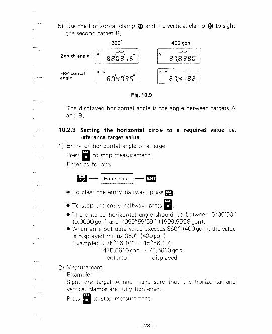
5) Use the horizontal clamp @ and the vertical clamp @ to sight the second target B.
360' 400 gon
Zenith angle 001-13 I C l 1 l r u -1 1 -1 5?.8358
Horizontal v] r] angle C # nun^^ V 1 1-1 -1 -1 S ?.r !B?
Fig. 10.9
The displayed horizontal angle is the angle between targets A and B.
10.2.3 Setting the horizontal circle to a required value i.e. reference target value
1 ) Entry of horizontal angle of a target.
Press B to stop measurement.
Enter as follows:
0 To clear the entry halfway, press
0 TO stop the entry halfway, press B. * The entered horizontal angle should be between 0°00'00"
(0.0000 gon) and 1999'59'59" (1999.9998 gon). When an input data value exceeds 360" (400gon), the value is displayed minus 360" (400gon). Example: 375°56'10" + 15°56'10"
475.5610 gon -t 75.5610 gon entered displayed
2) Measurement Example: Sight the target A and make sure that the horizontal and vertical clamps are fully tightened.
Press B 10 stop measurement.

Enter the required horizontal angle e.g. 15°36'20".
About I S -
Fig. 10.10
Target A has now been set to 15°36'20"
10.2.4 Repetition of angles Repetition of angles from -1 ,999°59'59" to 1 ,999°59'59" (-1,999.9998gon to 1,999.9998gon) is displayed by using m.
1 ) Press to select repetition of angle.
H I,, ...... Repetition of angle display
Fig. 10.12
2) Sight target A, and press 0&) and m 400 gon
Fig. 10.13
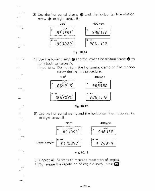
3) Use the horizontal clamp @ and the horizontal fine motion screw @ to sight target B.
360' 400 gon
Fig. 10.14
4) Use the lower clamp @ and the lower fine motion screw @ to turn back to target A. Important: Do not turn the horizontal clamp or fine motion
screw during this procedure.
360" 400 gon
Fig. 10.15
5) Use the horizontal clamp and the horizontal fine motion screw to sight target B.
360' 400 gon
Fig. 10.16
6) Repeat 4), 5) steps to measure repetition of angles. 7) To release the repetition of angle display, press m.

10.3 PREPARATION FOR DISTANCE MEASUREMENT
10.3.1 Prism constant correction 1 ) Remove the prism constant switch cover (D with a coin. 2) Use the screwdriver to turn the X l 0 mm index and X l mm
index to match the reflecting prism constant correction value. Example: Apply a prism constant correction of -30 mm:
-30 mm = -3 X l0 mm - 0 X 1 mm. Therefore, set the X l 0 index to C and the X l index to 0.
Note: The sign (+/-) of the SWxl value corresponds to the sign of the SWx l 0 value.
~ ~ 0 1 2 3 4 5 6 7 8 3
X I O l 2 , 3 4 5 6 7 8 9
Sian +l- corresoonds to SWX 10
Fig. 10.17
3) Replace the cover.
Prism constant values of Sokkisha reflecting prisms. The prism constant of the AP series prisms is 30 mm (the same value as the previous Sokkisha prism) using the prism spacer APOlS (standard accessory). The constant can be changed to 40 mm by removing the prism spacer.
PR03 APOIS+APOI APO l
Fig. 10.18
When using reflecting prisms with constant values other than the above, a prism constant correction of -99 mm to 159 mm can be set in steps of 1 mm using the X 10 and X l indices.

10.3.2 Atmospheric correction The SET3 is designed so that the correction factor is 0 for a temperature of +l 5OC and an atmospheric pressure of 760 mmHg. The correction factor is obtained from the pressure and tempera- ture as follows. 1 ) Measure the temperature and atmospheric pressure with a
thermometer and a barometer. Pressure can be obtained from weather station sea level data by correcting for altitude. For altitude correction see 15.2. To convert millibars to mmHg, multiply by 0.75. Example: 959 millibars
0.75 X 959 = 719 mmHg
2) Read the correction factor from the atmospheric correction tables on pages 70 and 71. Example: Temperature +25"C
Atmospheric pressure 750 mmHg Correction factor is t l 3 ppm.
Temperature
I PP-
Fig. 10.19
3) Set the ppm switch @ to t13. 4) To obtain the atmospheric correction factor by computation.
Example A: Using pressure in mmHg. 0.3872 X P
Atmospheric correction factor X = 278.96 - 1 + 0.003661 X t
P: Atmospheric pressure in mmHg t: Temperature in centigrade

4) To obtain the atmospheric correction factor by computation.
0.3872 X P Atmospheric correction factor X = 278.96 -
1 + 0.003661 X t P: Atmospheric pressure in mmHg t: Temperature in centigrade
Example: P = 750 mmHg, t = +25OC
To convert millibars to mmHg multiply by 0.75. Example: 959 millibar
0 . 7 5 ~ 959+719mmHg
5) The corrected slope distance is calculated by the formula:
D: Corrected slope distance d: 'The display of slope distance when ppm is set at 0 X: Correction factor in ppm
Example: Slope distance 2,010.000 m X = +5 ppm

10.3.3 Earth-curvature and refraction correction 1) Remove the internal switch cover 0 . 2) To correct horizontal distance and height difference for earth-
curvature and refraction, set switch 3 to ON with a screw- driver.
3) Replace the cover.
Earth-curvature and correction switch
-m O N -Correction is applied.
m m OFF-Correction is n o t applied.
refraction
Fig. 10.20
This correction is performed in the measurement of hori- zontal distance and height difference. The value displayed by the SET3 is computed by the follow- ing formula:
When the switch is ON Horizontal distance after correction
Height difference after correction l - K
V ' = S x c o s Z + - X S* xsin2 Z 2 R
When the switch is OFF Horizontal distance H = S x s i n Z Height difference V = S x c o s Z
S: Slope distance (value after atmospheric correction) Z: Zenith angle K: Atmospheric refraction constant (0.142) R : Radius of the earth (6.372 X 10⁶m)

Target
2 Average sea level __t Fig. 10.21
Example: Amount of correction at a zenith angle 70"
-1 1 200 1 500 1 I000 I500
H' - H (m) -0.002 -0.012 -0.047 -0.105
V' - V (m) 0.002 0.015 0.059 0.134
Note that the horizontal distance is a distance measured at the height of the surveying point above the sea level. I t is necessary to reduce this distance to the average sea level and to apply the local projection correction.
10.3.4 Prism sighting 1) Sight the centre of the reflecting prism with the telescope. 2) Set the return signal audio switch @ to P . 3 ) Set the power switch @ to ON and press m.
turns the power supplied to the EDM unit ON or OFF. Usually the power of the EDM unit turns OFF automatically after 1 second of inactivity and the power source mark dis- appears. But when m is pressed, power is supplied to the EDM unit for about 2 minutes to permit prism sighting. a. When power is supplied to the distance measurement unit
(EDM unit), the power source marking @ is displayed.

b. When the reflected light is received by the telescope, an audio signal is heard and the return signal lamp @ lights UP.
-
When the light intensity coming back from the prism is very high, the return signal lamp may light up, even for a slight mis-sighting. Make sure that the target centre is sighted correctly.
4) Switch off the audio target acquisition.
10.3.5 Mode selection 1) Select the mode switch @ to MEAS. for fine measurement,
or TRACK. for tracking.
measurement TRACK.: tracking
measurement
Fig. 10.22
MEAS.: Measures in mm units at first after 7 seconds and then every 5 seconds.
TRACK.: Measures in cm units at first after 7 seconds and then every 0.4 to 1 second.

10.4 DISTANCE MEASUREMENT
-Make sure that: a. The SET3 is set up correctly over the surveying point. b. The prism constant switch, the earth-curvature refraction
switch, and ppm switch are set correctly. c. Battery voltage is adequate. d. Indexing the vertical circle is complete.
10.4.1 Angle and distance measurement 1) Press H to stop angle measurement.
Fig. 10.23 U 2) Press and sight the centre of the reflecting prism. (See
10.3.4) 3) Press a to measure slope distance.
The following display appears showing that the slope distance measurement is being performed.
Display flashes
Fig. 10.24 1 m
4) The slope distance and the zenith angle will be displayed after about 7 seconds.
_I_+ Zenith angle s i r22d I i.60~)
Slope distance: 234.567 m Fig. 10.25 (fine measurement)
Slope distance will continue to be measured every 5 seconds.
- 32 -

9 When the following keys are pressed instead of a in step 3 ) , the measurement corresponding to each key is per- formed.
Key During operation measurement
Measured value
j4 Horizontal 33 ;88'5', distance
71 1 . 1 1-1 I I C L II * Zenith angle - I] Height
3515'5 3 , difference
Fig. 10.26
5) Press B to stop measurement. * Horizontal and zenith angles are displayed in real time.
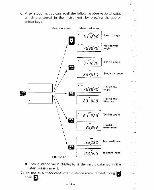
6) After stopping, you can recall the following observational data, which are stored in the instrument, by pressing the appro- priate keys.
Key operation Measured value
1 &'h 1 zenith angle
1 v/ Horizontal '453893 angle
,/ , 1 8 {722gr' 1 Zenith angle
4 1 d l
/ / 1 23 y.55 1 Slope distance
Horizontal angle
Horizontal distance
Height
Fig. 10.27
Each distance value displayed is the result obtained in the latest measurement.
7) To use as a theodolite after distance measurement, press then p. H

10.4.2 Measurement of coordinates
Vertical l ine 1
L: Horizontal distance
\ Instrument stat ion (X,, Y , )
Fig. 10.28 \--Start po in t (0, 0)
1 ) The SET3 computes coordinates using the formulas: N (X)-coordinate = X. + L cos O H E (Y)-coordinate = Yo + L sin O H
2) The observation procedure is the same as 10.4.1. Because the N component is positive for north and the E component is positive for east in plane rectangular coordinates, you should select the horizontal angle right and set the horizontal circle to zero on north.
31 For example: 0'
* A
Y/E
Fig. 10.29
Point No.
0 A
B
Horizontal distance
- 443.387
750.453
Horizontal angle
-
20" 1 5'1 0" (22.5030 gon)
225" 32'50" (250.6080 gon)
N-coordinate E-coordinate
610.000 1,025.974
84.442
770.000 923.484
234.306

4) Press to stop measurement. Measure coordinates as follows.
a. Entry of instrument station coordinates
@ To clear the entry halfway, press m. @ TO stop the entry halfway, press H. @ The range of coordinates is between -9,999.999 m
(-9,999.99 ft) and 9,999.999 m (9,999.99 ft). The coordinates are retained in the memory of the SET3 for about 5 days even when the power switch is turned OFF. After that, the coordinates become (0, 0).
Example: Entering the instrument station coordinates (610, 770)
Enter the V U V V
ri n n n N-coordinate.
Stored coordinates are displayed.
1 6 :2?22 1 ;,gut 1 . 1 --mmmm
Enter the -I -I CI 0 ,-I ,-I E-coordinate.
Fig. 10.30
b. Confirmation of instrument station coordinates
Confirm the displayed coordinates
@ To correct the stored coordinates, re-enter them.

c. Measurement of target point coordinates
1 1 1 g 2 3 r g r . j Measurement stop
During Measured measurement coordinates
Fig. 10.31
10.4.3 Remote elevation measurement
At certain surveying points e.g. power transmission lines or cables supporting bridges, etc., a reflecting prism cannot usually be positioned. In such cases the remote elevation measurement makes height differences easy to measure.
h = h l +h2 h, = S (sin 6Jzl X cot O Z 2 -COS 6Jz l )
Fig. 10.32
1) Between the ground and the object a. Set up a reflecting prism under the object and measure the
prism centre height from the ground with a tape measure. @ Use an optical plummet to set the prism accurately.
b. Enter the height, h, measured in step a., as a positive value, as setting-out data.

Example: The prism centre height from the ground is 1.523 m
n n n n Enter the data V!-l Cl U l
Fig. 10.33
c. Sight the reflecting prism and press a. Press a after the distance measurement data i s displayed.
1 ;g275 6 1 Measurement stop
During measurement Measured value
Fig. 10.34
The measured value is stored in the SET3. d. Press a, then a.
About
S.0 A
During measurement
1 {5,?3. l Measured value
Fig. 10.35
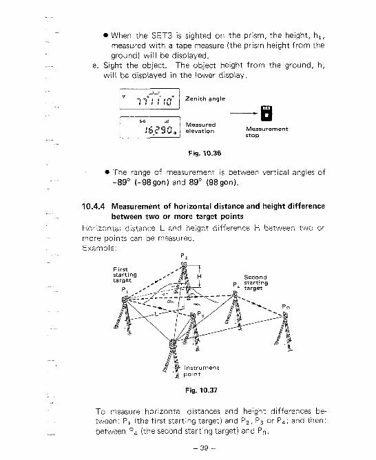
When the SET3 is sighted on the prism, the height, h,, measured with a tape measure (the prism height from the ground) will be displayed.
e. Sight the object. The object height from the ground, h, will be displayed in the lower display.
Measurement stop
Fig. '10.36
* The range of measurement is between vertical angles of -89" (-98gon) and 89" (98gon).
10.4.4 Measurement of horizontal distance and height difference between two or more target points
Horizontal distance L and height difference H between two or more points can be measured
Fig. 10.37
To measure horizontal distances and height differences be- tween: PI (the first starting target) and P,, Pg or P4; and then: between P, (the second starting target) and P".
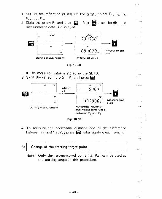
l ) Set up the reflecting prisms on the target points P,, P,, P,, P4,. . . ,P".
2 ) Sight the prism P, and press @. Press a after the distance measurement data is displayed.
--B During measurement Measured value
Fig. 10.38
The measured value is stored in the SET3. 3) Sight the reflecting prism P, and press @.
.j During measurement Horizontal distance
and height difference between P, and PZ
Fig. 10.39
4) To measure the horizontal distance and height difference between P, and P g , P4, press after sighting each prism.
5) Change of the starting target point.
Note: Only the last-measured point (i.e. Pq) can be used as the starting target in this procedure.
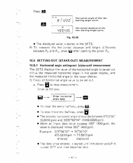
Press a. ' Horizontal angle of the new
" " 8 { :,g;':( starting target point. -. _-.A
r---iI Horizontal distance of the I ,,00,,3C , ,,-, -, , -, ,, I new starting target point. I. . I
Fig. 10.40
* The displayed value is stored in the SET3. 6) To measure the horizontal distance and height difference
between P, and P,, press B after sighting the prism P,.
10.5 SETTING-OUT (STAKE-OUT) MEASUREMENT
10.5.1 Horizontal angle setting-out (stake-out) measurement The SET3 displays the value of the horizontal angle to be set out minus the measured horizontal angle in the upper display, and the measured horizontal angle in the lower display. 1 ) Entry of horizontal angle value to be set out.
a. Press m to stop measurement.
Enter as follows:
0 To clear the entry halfway, press m. * To stop the entry halfway, press . B 8 The entered horizontal angle should be between 0°00'00"
(0.0000gon) and 1999~59'59" (1999.9998 gon). * When an input data value exceeds 360' (400 gon), the
value is displayed minus 360° (400gon).
Example: 375°56'10" -+ 15°56'10" 475.561 0 gon + 75.561 0 gon
entered displayed
e The data once entered is stored until the power switch is turned OFF and then becomes zero.
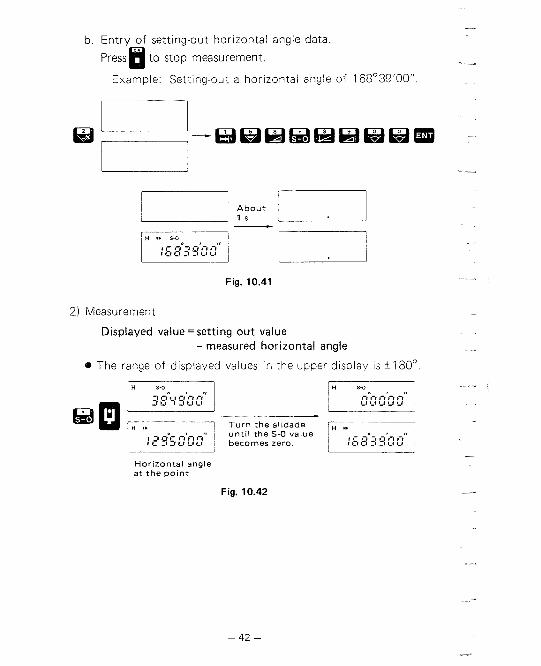
b. Entry of setting-out horizontal angle data.
~ r e s s H to stop measurement.
Example: Setting-out a horizontal angle of 168°39'00"
Fig. 10.41
2) Measurement
Displayed value = setting o u t value - measured horizontal angle
The range of displayed values in the upper display is +180°.
g:-tg'ngrr 1 b
T u r n t h e al idade
Ho r i zon ta l angle a t t h e p o i n t
Fig. 10.42

10.5.2 Distance setting-out measurement
1 ) Setting out a distance. The SET3 displays the measured distance minus the distance to be set out
2) Entry of distance value to be set out. The distance must be entered for slope distance, horizontal distance or height difference measurements.
Press B to stop measurement Enter as follows.
a - I Enter data I - To clear the entry halfway, press m To stop the entry halfway, press B. The entered distance should be between -9999.999 m and 9999.999 m. The data once entered is stored until the power switch is turned OFF and then becomes 0.
3) Confirmation of setting out distance data.
Confirm the displayed
To correct the stored data, re-enter i t 4) Measurement
The following distance measurements can be performed with m.
Key operation
Slope distance setting-out
Horizontal distance setting-out
\- Height difterence setting-out
Fig. 10.43

Example Setting-out a hor~zontal d~stance of 90 5 m
a. Entry of distance value to be set out.
nnnn Enter the data.
Stored data is displayed.
About / . 1 0.5s
Fig. 10.44
b. Measurement
During Measured distance measurement and horizontal angle
Fig. 10.45
The measured horizontal distance is 1.246 m longer than the setting-out distance (90.5 m).

11. SELF DIAGNOSIS
If there is any fault in the measuring function, the error codes shown in the following table will be displayed.
I Display I Meaning I Action
Battery voltage is too low.
Replace the battery with a charged one, or charge the battery.
- I l-i l-c C 1 l J I - l *Error when measur-
ing a horizontal angle.
Reset to the horizpn- tal angle 0" (0 gon).
when measur- Ing a zenith angle.
Index the vertical circle again.
Compensator range error. Tilt angle ex- ceeds -3'.
1- 1 t -1 C r f f Compensator range error. Tilt angle ex- ceeds +3'.
Level the SET3 again.
Incoming ref iected light decreased during measurement. Incom- ing reflection was dis- turbed.
Incoming reflection is totally absent when the instrument is ready for distance measuring.
Sight the reflecting prism again. Increase the number of the reflecting prisms for a long dis- tance. Measure the distance again confirming the condition with the return signal lamp or sound.

Display
t- :l I t-l C C r y
Meaning
Error when measuring the initial slope dis- tance during either remote elevation or horizontal distance between two points measurement.
During remote eleva- tion measurement, the vertical angle is more than t 8g0 ( t98gon) or the measured dis- tance is more than t9,999.999 m.
The measured dis- tance is more than rt 19,999.999 m (+ 19,999.99 f t ) .
During horizontal dis- tance between two points measurement, L' (horizontal d i ~ t . ~ ) is more than 1 O7 m.
Act ion
Sight the reflecting prism and perform slope distance meas- urement again.
Press H to stop meas-
uring.
Press H to stop meas-
uring.
* If the SET3 is rotated faster than four revolutions per second, the error indication "E100" or "E101" is displayed.
When the error indication "E" appears with any number other than the ones above, please contact our agent.

12. OPTIONAL ACCESSORIES
12.1 DIAGONAL EYEPIECE DE18
The diagonal eyepiece is convenient for steep observations and in places where space around the instrument is limited. Remove the eyepiece @ by loosening the mounting ring, and screw in the diagonal eyepiece.
Setting up the DE18
Fig. 12.1
12.2 ELECTRONIC FIELD BOOK SDR2
The SDR2 collects and stores slope distance, zenith and hori- zontal angle data from the SET3. Calculations can be performed on the data so that the measure- ments can be verified in the field. The stored data can be transmitted to a data processing system.
Fig. 12.2
- 47 -
SDR2 specifications Power source: "AA" (UM3) X 4 Memory type: CMOS
RAM 16K or 32K ROM 16 K
Keyboard: 33 keys Display: LCD Baud rate: 300, 600, 1 200,
2400,4800 bps Operating temperature
range: 0 to 50°C Weight: 450 g
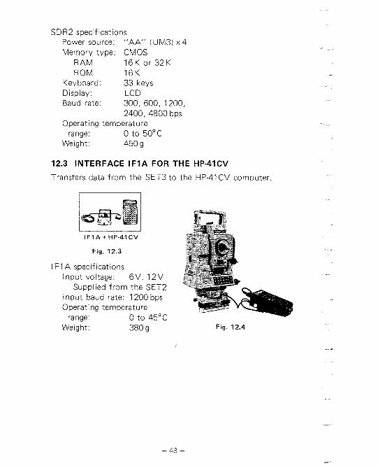
12.3 INTERFACE l F l A FOR THE HP-41CV
Transfers data from the SET3 to the HP-41 CV computer.
I F l A + HP-41CV
Fig. 12.3
I F1 A specifications lnput voltage: 6V, 12V
Supplied from the SET2 lnput baud rate: 1200 bps Operating temperature
range: 0 to 45°C Weight: 380 g Fig. 12.4

13. CHECKS A N D ADJUSTMENTS
The SET3 may be affected by sudden changes in weather condi- tions and excessive vibration. This can result in inaccurate surveying. Therefore, IT IS IMPORTANT TO CHECK AND ADJUST THE SET3 BEFORE AND DURING USE in the follow- ing order.
13.1 ANGLE MEASURING FUNCTION
13.1 . l Plate level 13.1.2 Circular level 13.1.3 Index error of the t i l t angle sensor 13.1.4 Reticle 13.1.5 Perpendicularity of the reticle to the horizontal axis 13.1.6 Coincidence of the distance measuring axis with the
reticle 13.1.7 Optical plummet
13.1.1 Plate level The glass tube of the plate level is sensitive to temperature change or shock. Be sure to check the plate level @ before use. l) See Figs. 13.1 and 13.2 for relation between bubble movement
and rotation of the levelling foot screws.
Fig. 13.1 Fig. 13.2
2) Turn the upper part of the SET3 until the plate level is perpen- dicular to a line between levelling screws A and B. Then centre the bubble using the levelling screw C.
Level l ing screw
P la te level
A
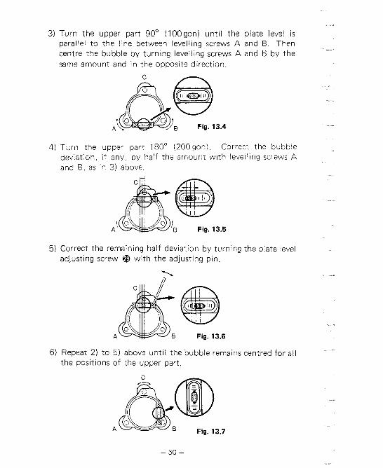
3) Turn the upper part 90' (100gon) until the plate level is parallel to the line between levelling screws A and B. Then centre the bubble by turning levelling screws A and B by the same amount and in the opposite direction.
A L0 Fig. 13.4
4) Turn the upper part 180° (200gon). Correct the bubble deviation, if any, by half the amount with leveliing screws A and B, as in 3) above.
5) Correct the remaining half deviation by turning the plate level adjusting screw @ with the adjusting pin.
'1,
A B Fig. 13.6
6) Repeat 2) to 5) above until the bubble remains centred for all the positions of the upper part.

13.1.2 Circular level When the plate level adjustment is complete, the circular level @ should be checked. Note the direction off-centre of the bubble. Loosen the adjusting screw farthest f rom that direction and tighten the other adjusting screws t o centre the bubble.
'LJ
Fig. 13.8
13.1.3 Index error of the tilt angle sensor When the circular level adjustment is complete, the index error should be checked. 1) After indexing the vertical circle, tighten the vertical clamp a. 2) Press and QQ t o set the horizontal circle t o zero, then press
m t o display the t i l t angle.
Fig. 13.9
3) Loosen the horizontal clamp and turn the upper part through 180°?r5' (200gon+0.1 gon).
Fig. 13.10
- 51 -

a + b ,
4) Calculate - = ~ndex error c 2
Example: - 10" + 9" = -0.5"
2 5) If the index error is less than 5", no adjustment is necessary.
For adjustment remove the sensor index adjustment cover @ . Return to 0' horizontal angle position. Using a suitable flat screwdriver,adjust the internal screw until the upper display don = a - c. Turn the upper part through 180'. Adjust the internal screw until the upper display dlgo0 = b - C.
Sensor index adjusting screw
Fig. 13.11
Example: - 12" + (-6") =
If a = -12", b = -6", index error c = 2

13.1.4 Reticle When the index error adjustment is complete, the position of the reticle should be checked. 1) Level the SET3. Select a clear target at a horizontal distance
of 50 to l00 m.
50 to l OOm ..---.--------------------------....-.--..-------------......
Fig. 13.12
2) After indexing the vertical circle, sight the target and take the horizontal angle reading in position V l , e.g. a1 = 18"34'00" (a1 = 20.6296gon) and the zenith angle reading, e.g. b l = 90°30'10" ( b l = 100.5586 gon).
Fig. 13.13
3) Next in position V2, sight the same target. Take the horizontal angle reading, e.g. a, = 198°34'10" (a, = 220.6327gon) and the zenith angle reading, e.g. b, = 269°30'02" (b, = 299.4451 gon).
4) Calculate a, - al, b, + bl. a, - a1 = 198°34'10" - 18°34'00" = 180°00'10" (a, - a1 = 220.6327 gon - 20.6296 gon = 200.0031 gon) b, + b l = 269°30'02" + 90°30'10" = 360°00'12" (b, + br = 299.4451 gon + 100.5586 gon = 400.0037 gon)

5) When the reticle is in the normal position, your results should show that a, - al is within 20" of 180" (200 gon) and b, + b l is within 20" of 360" (400gon). If the difference of a, - a1 from 180' (200gon) or b, + bl from 360" (400gon) is 20" or greater after several checks, adjust as foIiows.
6) While still in position V2, use the horizontal and vertical fine motion screws to adjust the lower display, a,, and the upper display, b,, to read:
Example:
If a [ = 1 8"34'00" a, = 198O34'26" b l = 90°30'1 2" b, = 269"30f12"
7) Look through the telescope. The target is seen shifted from the vertical and horizontal reticle lines.
8) Remove the reticle adjustment cover @ .
Adjusting screws
fB
Fig. 13.14

9) Adjust the reticle sideways with the adjusting screws un t~ l the target is centrally w~th in the vert~cal I~nes, and then adjust ~t up or down with the screws until the target is centrally w i t h~n the horizontal lines
Fig. 13.15 4 Fig. 13.16
10) Replace the cover
The adjustment is very delicate. If i t is difficult, please contact our agent.
N.B. If amount of the reticle shift is too large, dis- tance measuring may be affected. Do not adjust the reticle more than 20" (0.006gon).

13.1.5 Perpendicularity of the reticle to the horizontal axis 1 ) Select and sight a clear target on the upper part A of the
vertical reticle line Fig. 13.17. 2) Turn the telescope slowly upward with the vertical fine
motion screw @ until the target slides to the lower part B, Fig. 13.18. If the target is still centrally within the vertical lines no adjustment is necessary. If necessary, adjust as follows.
Fig. 13.17 Fig. 13.18
3) If the target at B is not on the reticle, slightly loosen the lower adjusting screw and either the left or right adjusting screw with the adjusting pin, then rotate the reticle plate until the reticle is perpendicular to the horizontal axis. Retighten the screws by the same amount.
Fig. 13.19
4) Recheck the reticle position as in 13.1.4.

13.1.6 Coincidence of the distance measuring axis with the reticle
When the reticle has been checked, check the distance measuring axis relative to the reticle as follows. 1 ) Level the SET3. Set up the reflecting prism at a horizontal
distance of 50 to 100 m.
Fig. 13.20
2) Sight the reflecting prism centre and take the horizontal and zenith angle readings. (H and Z respectively)
Fig. 13.21
3) Press m on the keyboard and make sure the return signal lamp @ lights up.
4) Four more readings are necessary. Turn the horizontal or vertical fine motion screw slowly until the return signal lamp goes off. Then take readings. Readings H1, H,: when the telescope is directed to the left
(right) of the sighted direction in 2) above. Readings Z,, Z b : when the telescope is directed above
(below) the sighted direction in 2) above. 5) Check the differences of HI (H,) against H, and Z, (Zb)
against Z. When the four differences obtained are larger than 2.5' (0.046 gon), the coincidence is normal. If the differences obtained are less than 2.5' (0.046gon1, please contact our agent.

13.1.7 Optical plummet 1 ) Level the SET3. Centre a surveying point in the reticle of the
optical plummet. Loosen the horizontal clamp and turn the upper part through 180' (200gon). If the surveying point is still centred, no adjustment is necessary.
2) If the surveying point is off-centre, correct half the deviation with the four adjusting screws, and correct the remaining half with the levelling screws. .
Fig. 13.22
3) Repeat the adjustment if necessary.

13.2 DISTANCE MEASURING FUNCTION
13.2.1 Check flow chart
Power switch O N l l Yes .. r-leesesas'.l NO I:_.,..; displayed? (1
18888888:
Power swttch OFF
Replace or charge
Sight reflecting prism correctly and press
Return s~gnal lamp ON?
I Cover object~ve lens
Return sigml lamp out? <** Replace or charge the batterv I check c;n'tact of I battery term~nals
L R e m o v e r c o v e r 1 Power switch ON
Select MEAS. and
Audio tone heard?
NO - dlsp1ayed7
ssssssa, l Yes
Yes
Contact our agent
Fig. 13.23

13.2.2 Additive distance constant The additive distance constant of the SET3 is adjusted to 0 before delivery. However, the additive constant can change with time and so should be determined periodically and then used to correct distances measured. 1) Determining the additive distance constant.
The most reliable method of determining the additive distance constant is to test the SET3 on an established base line with a maximum range of approximately 1,000 m, and with 6 to 8 intermediate stations spaced at multiples of the instrument unit length, which is 10 m. Measurements should be taken in all combinations of the 6 to 8 stations. If an additive distance constant of greater than 5 mm is found please contact our agent.
2) Confirmation of the additive distance constant K if a base line is not available. a. Select points A and B on flat ground about 100 m apart,
and C in the middle. b. Set up the SET3 at A, and measure the distance AB.
Note: Be sure prism height is the same as the height of the SET3 objective lens centre. If ground is not level, use an automatic level to set correct instrument heights of all points.
About l O O m
A B
Fig. 13.24

c. Shift the SET3 to C, and measure the distance CA and CB.
Fig. 13.25
d. Compute the additive distance error K using the formula:
- - - K = S - ( C A + C B )
AB, CA, CB: Average of ten measurements.
e. Obtain K value three times. If all K are greater than 5 mm, contact our agent.

14. FOR ANGLE MEASUREMENT OF THE HIGHEST ACCURACY
14.1 LEVELLING BY REFERRING TO THE DISPLAY
For the most accurate measurement of horizontal angles, particu- larly for steep observations, the SET3 should be levelled using the t i l t angle display. The index error of the t i l t angle can be eliminated by taking readings on O0 and 180'. 1 ) Level with the plate level @. 2) Tighten the vertical clamp @ with the telescope approxi-
mately horizontal. 3) Loosen the horizontal clamp @ and turn the upper part of the
SET3 until the plate level is parallel to a line between levelling screws A and B. Then press and to set the horizontal angle t o O0 (Ogon)
Fig. 14.1 Fig. 14.2
4) Press to display the t i l t angle.
Fig. 14.3

5) Wait for 3 to 4 seconds until the t i l t angle reading is steady. Then press m and a.
Fig. 14.4
6) Turn the upper part of the SET3 through 180' (200gon).
Fig. 14.5
7) Wait for 3 to 4 seconds until the t i l t angle reading is steady. Then press and a.
n;1 n'n a" L l U V U J I . -'- l
Fig. 14.6
8) Referr~ng to the t i l t angle reading, level the SET3 using level- ling screws A or B until the value in the display IS O O f l " .
Fig. 14.7

9 ) T u r n the upper part o f the SET3 through 90' (100gon) .
gnn 7 3 n 1 " " 1 Fig. 14.8
10) Wait fo r 3 t o 4 seconds un t i l the t i l t angle reading is steady. Then referring to the tilt angle reading, level the SET3 using the levelling screw C un t i l the value i n the display is OO+l" .
Fig. 14.9
1 1 ) Press t o release the t i l t angle display
Fig. 14.10
The vertical axis error is n o w minimized.

14.2 MANUALLY INDEXING VERTICAL CIRCLE BY v1, v 2
Like every theodolite, the SET3 will have a verticai index error. A vertical index error can be removed as follows. 1 ) Turn the power OFF, remove the internal switch cover and
set switch 6 to ON. (When switch 6 is ON, the automatic indexing of the vertical circle by transitting the telescope is inactive.)
2) After levelling the SET3, turn the power ON and make sure that the display appears as shown below.
360' 400 gon
rrt-t n'n n" I 1 n n e-1 r t ,-l I j 1, 1 1 1 1 1 1 1 1 ,-l ,-l C l CI *-I
Fig. 14.1 1
3) In position V l , accurately sight a clear target at a horizontal distance of about 30 m.
Fig. 14.12
4) Press m and m. 360" 400 gon
Fig. 14.13

5) Next in position V2, accurately sight the same target.
Fig. 14.14
6) Press and a. When the vertical circle is indexed, the display appears as below.
360" 400 gon
Zenith angle
Horizontal angle
Fig. 14.15
If the power sw~tch has been turned OFF, the vertical circle must be ~ndexed again. When moving the SET3 after measurement, turn the power OFF.

15. FOR DISTANCE MEASUREMENT OF THE HIGHEST ACCURACY
15.1 ACCURACY OF MEASUREMENT OF ATMOSPHERIC CONDITIONS
The relation between measured distance and the velocity of light is given by
T: The period between light emission and reception. C: The velocity of light in the air.
C,: The velocity of light in a vacuum. n: Refractive index of the air.
The measured distance is affected by variation in the refractive index
d D - d n . D
- dn (or dD + D . dn) n
Therefore, the accuracy of measurement of the refractive index must be the same as that of the measured distance. To calculate refractive index to an accuracy of 2 ppm, tempera- ture must be measured to within 1°C and pressure to within 5 mmHg.
15.2 TO OBTAIN THE ATMOSPHERIC PRESSURE
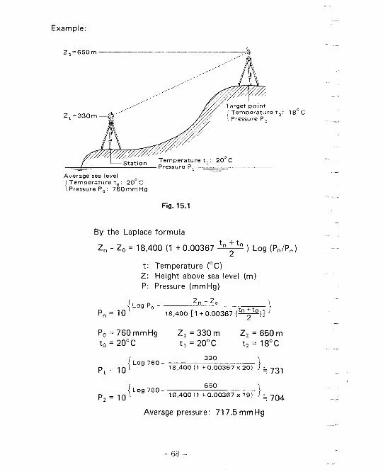
To obtain the average refractive index of the air throughout the measured light path, you should use the average atmospheric pressure. In flat terrain there is little variation in the atmospheric pressure. In mountains, the following calculation should be used.
Example:
Fig. 15.1
By the Laplace formula
Zn - Z, = 18,400 (1 + 0.00367 &-?S! Log (P,/p,)
t: Temperature ("C) Z: Height above sea level (m) P: Pressure (mmHg)
P, = 760 mmHg Z , = 330 m Z2 = 650 m to = 20°C t , = 20°C t2 = 18°C
{Log 760 - 330
P, = 10 18,400(1 t0.00367 ~ 2 0 ) 1 ; 731
Average pressure: 71 7.5 mmHg

16. PRECAUTIONS AND MAINTENANCE
16.1 PRECAUTIONS
1) When the SET3 is not used for a long time, check i t at least once every three months.
2) Handle the SET3 with care. Avoid heavy shocks or vibration.
3) If any trouble is found on the rotatable portion, screws or optical parts (e.g. lens), contact our agent.
4) When removing the SET3 from the carrying case, never pull it out by force. The empty carrying case should then be closed to exc!ude dust.
5) Never place the SET3 directly on the ground.
6) Never carry the SET3 on the tripod to another site.
7) Protect the SET3 with an umbrella against direct sunlight, rain and humidity.
8) When the operator leaves the SET3, the vinyl cover should be placed on the instrument.
9) Do not aim the telescope at the sun
10) Always switch the power off before removing the internal battery.
11) Always remove the battery from the SET3 when returning it to the case.
12) Do not wipe the display @, keyboard @ or the carrying case with an organic solvent.
13) When the SET3 is placed in the carrying case, follow the layout plan.
14) Make sure that the SET3 and the protective lining of the carrying case are dry before closing the case. The case is hermetically sealed and if moisture is trapped inside, damage to the instrument could occur.

16.2 MAINTENANCE
1 ) Wipe off moisture completely if the instrument gets wet during survey work.
2) Always clean the instrument before returning it to the case.
brush first, to remove minute particles. Then, after pro- viding a little condensation by breathing on the lens,
3) Store the SET3 in a dry room where the temperature remains fairly constant.
4) If the battery is discharged excessively, its life may be shortened. Store i t in a charged state.
5) Check the tripod for loose fit and loose screws.

17. ATMOSPHERIC CORRECTION CHARTS
(Metric)
Pressure (rnrnHg)
The chart shows the correction every two ppm, while the atmos-
pheric correction can be applied to the SET3 for every ppm

(English)
Pressure (inchHg)
The chart shows the correction every two ppm, while the atmos- pheric correction can be applied to the SET3 for every ppm.
The specifications and general appearance of the instrument may be altered at any time and may differ from those appearing in catalogues and the operator's manual.

18 . INDEX
Page . . . . . . . . . . . . . . . . . . . . . . . . . . . . . . . . . . Accessories 9.11. 47
Angle measurement . . . . . . . . . . . . . . . . . . . . . . . . . . . . . . . . . 21 Angle measurement modes . . . . . . . . . . . . . . . . . . . . . . . . . . . 22 Atmospheric correction . . . . . . . . . . . . . . . . . . . . . . . . . . . . . 27 Audioswitch . . . . . . . . . . . . . . . . . . . . . . . . . . . . . . . . . . . . . 30 Batteries . . . . . . . . . . . . . . . . . . . . . . . . . . . . . . . . . . . . . . . . . 9 Circular level adjustment . . . . . . . . . . . . . . . . . . . . . . . . . . . . 51
. . . . . . . . . . . . . . . . . . . . . . . . . . . . Coordinate measurement 35 Curvature and refraction correction . . . . . . . . . . . . . . . . . . . . 29 Display limit . . . . . . . . . . . . . . . . . . . . . . . . . . . . . . . . . . . 24. 36 Display symbols . . . . . . . . . . . . . . . . . . . . . . . . . . . . . . . . . . . 13
. . . . . . . . . . . . . . . . . . . . . . Distance measuring axis checking 57 Distance measurement . . . . . . . . . . . . . . . . . . . . . . . . . . . . . . 32 Distance measurement checking . . . . . . . . . . . . . . . . . . . . . . . 60 Distance measurement flow chart . . . . . . . . . . . . . . . . . . . . . 59 Error codes . . . . . . . . . . . . . . . . . . . . . . . . . . . . . . . . . . . . . . . 45 Features . . . . . . . . . . . . . . . . . . . . . . . . . . . . . . . . . . . . . . . . . 4 Focussing . . . . . . . . . . . . . . . . . . . . . . . . . . . . . . . . . . . . . . . . 20 Horizontal distance between two points . . . . . . . . . . . . . . . . 39 Indexing manually . . . . . . . . . . . . . . . . . . . . . . . . . . . . . . . . . 65 Instrument part names . . . . . . . . . . . . . . . . . . . . . . . . . . . . . . 1
. . . . . . . . . . . . . . . . . . . . . . . . . . . . . . . . Keyboard functions 14 Levelling with the display . . . . . . . . . . . . . . . . . . . . . . . . . . . . 62 Maintenance . . . . . . . . . . . . . . . . . . . . . . . . . . . . . . . . . . . . . . 70 Optical plummet adjustment . . . . . . . . . . . . . . . . . . . . . . . . . 58 Parallax . . . . . . . . . . . . . . . . . . . . . . . . . . . . . . . . . . . . . . . . . . 21 Parts per million . . . . . . . . . . . . . . . . . . . . . . . . . . . . . . . . . . . 27
. . . . . . . . . . . . . . . . . . . . . . . . . . . . . . . Plate level adjustment 49 . . . . . . . . . . . . . . . . . . . . . . . . . . . . . . . . . . . . Power supplies 9
Powering up the SET3 . . . . . . . . . . . . . . . . . . . . . . . . . . . . . . 18 Precautions . . . . . . . . . . . . . . . . . . . . . . . . . . . . . . . . . . . . . . . 69 Prism constant . . . . . . . . . . . . . . . . . . . . . . . . . . . . . . . . . . . . 26
. . . . . . . . . . . . . . . . . . . . . . . . . . . . . . . . . . . . . Recalling data 34 . . . . . . . . . . . . . . . . . . . . . . . Remote elevation measurement 37
Page Repeti t ion o f angle . . . . . . . . . . . . . . . . . . . . . . . . . . . . . . . . . 24 Reticle adjustment . . . . . . . . . . . . . . . . . . . . . . . . . . . . . . . . . 53 Right and left angles . . . . . . . . . . . . . . . . . . . . . . . . . . . . . . . . 22 Setting u p over a point . . . . . . . . . . . . . . . . . . . . . . . . . . . . . . 20 Specifications . . . . . . . . . . . . . . . . . . . . . . . . . . . . . . . . . . . . . 5 Setting-out (stake-out) measurement . . . . . . . . . . . . . . . . . . . 41 Standard equipment . . . . . . . . . . . . . . . . . . . . . . . . . . . . . . . . 8
. . . . . . . . . . . . . . . . . . . . . . . . . . . . . . . . . . Switches. internal 17 T i l t angle sensor adjustment . . . . . . . . . . . . . . . . . . . . . . . . . . 51 Tracking mode . . . . . . . . . . . . . . . . . . . . . . . . . . . . . . . . . . . . 31 Zenith angle compensation . . . . . . . . . . . . . . . . . . . . . . . . . . . 19