TECHNICAL MANUAL HEADQUARTERS, … · THEODOLITE, DIRECTIONAL; 1-SECOND GRADUATION, ... of the...
104
TM 5-6675-306-14 TECHNICAL MANUAL HEADQUARTERS, DEPARTMENT OF THE ARMY No. 5-6675-306-14 WASHINGTON, D. C., 23 July 1975 Operator, Organizational, Direct Support and General Support Maintenance Manual THEODOLITE, DIRECTIONAL; 1-SECOND GRADUATION, 5.9 IN.LONG TELESCOPE: DETACHABLE TRIBRACH W/ACCESSORIES AND TRIPOD (WILD HEERBRUGG MODEL 12-74DEG) NSN 667500-334-65335 REPORTING ERRORS AND RECOMMENDING IMPROVEMENTS You can help improve this manual. If you find any mistake or if you know of a way to improve the procedures, please let us know. Mail your letter, DA Form 2028 (Recommended Changes to Publications and Blank Forms), or DA Form 2028-2 located in the back of this manual direct to: Commander, U.S. Army Troop Support Command, ATTN: AMSTR-MCTS, 4300 Goodfellow Boulevard, St. Louis, MO 63120-1798. A reply will be furnished directly to you. Paragraph Page CHAPTER 1. INTRODUCTION Section I. General ................................................................................................. 1-1-1-6 1-1 II. Description and data .............................................................................. 1-7-1-9 1-1 CHAPTER 2. OPERATING INSTRUCTIONS Section I. Service upon receipt of equipment ........................................................ 2-1-2-3 2-1 II. Movement to a new worksite ................................................................... 2-4, 2-5 2-20 III. Controls and instruments ....................................................................... 2-6, 2-7 2-20 IV. Operation under usual conditions ........................................................ 2-8-2-10 2-25 V. Operation under unusual conditions .................................................. 2-11-2-18 2-36 CHAPTER 3. OPERATOR/CREW MAINTENANCE INSTRUCTIONS Section I. Basic issue items list and items troop installed or authorized ...................... 3-1 3-1 II. Lubrication instructions ............................................................................ 3-2, 3-3 3-1 III. Preventive Maintenance Checks and Service ........................................ 3-4, 3-5 3-4 IV. Troubleshooting ........................................................................................ 3-6 3-4 V. Maintenance of Lamp Fitting and Battery Box ....................................... 3-7,3-8 3-6 CHAPTER 4. ORGANIZATIONAL MAINTENANCE INSTRUCTION Section I. Service upon receipt of equipment ............................................................. 4-1 4-1 II. Movement to a new worksite........................................................................ 4-2 4-1 III. Repair parts, special tools and equipment ............................................... 4-3-4-5 4-1 IV. Lubrication instructions ............................................................................... 4-6 4-1 V. Preventive maintenance checks and services ....................................... 4-7,4-8 4-2 VI. Troubleshooting .......................................................................................... 4-9 4-2 VII. Carrying case and haversack ............................................................. 4-10 - 4-12 4-3 VIII. Sunshade ......................................................................................... 4-13,4-14 4-7 IX. Tribrach assembly ............................................................................ 4-16,4-16 4-7 X. Illumination mirrors .............................................................................. 4 -17, 4-18 4-9 XI. Tripod assembly, plumb bob, and tripod wrench .................................. 4-19, 4-21 4-12 XII. Accessories ...................................................................................... 4-22-4-29 4-16 CHAPTER 5. DIRECT SUPPORT AND GENERAL SUPPORT MAINTENANCE INSTRUCTIONS Section I. Repair parts, special tools and equipment...............................................5 -1-- 5-3 5-1 II. Troubleshooting ......................................................................................... 5-4 5-3 III. Removal and installation of major components and auxiliaries .............. 5-5 5-8 5-4 CHAPTER 6. REPAIR OF TRIBRACH ASSEMBLY Section I. General ..................................................................................................... 6-1 6-1 II. Tribrach assembly, components ............................................................. 6-2 - 6-4 6-1 Change 2 i
Transcript of TECHNICAL MANUAL HEADQUARTERS, … · THEODOLITE, DIRECTIONAL; 1-SECOND GRADUATION, ... of the...

TM 5-6675-306-14TECHNICAL MANUAL HEADQUARTERS,
DEPARTMENT OF THE ARMYNo. 5-6675-306-14 WASHINGTON, D. C., 23 July 1975
Operator, Organizational, Direct Support andGeneral Support Maintenance Manual
THEODOLITE, DIRECTIONAL; 1-SECOND GRADUATION,5.9 IN.LONG TELESCOPE: DETACHABLE TRIBRACH
W/ACCESSORIES AND TRIPOD(WILD HEERBRUGG MODEL 12-74DEG)
NSN 667500-334-65335REPORTING ERRORS AND RECOMMENDING IMPROVEMENTS
You can help improve this manual. If you find any mistake or if you know of a way to improve theprocedures, please let us know. Mail your letter, DA Form 2028 (Recommended Changes to Publicationsand Blank Forms), or DA Form 2028-2 located in the back of this manual direct to: Commander, U.S.Army Troop Support Command, ATTN: AMSTR-MCTS, 4300 Goodfellow Boulevard, St. Louis, MO63120-1798. A reply will be furnished directly to you.
Paragraph PageCHAPTER 1. INTRODUCTION
Section I. General ................................................................................................. 1-1-1-6 1-1II. Description and data.............................................................................. 1-7-1-9 1-1
CHAPTER 2. OPERATING INSTRUCTIONSSection I. Service upon receipt of equipment ........................................................ 2-1-2-3 2-1
II. Movement to a new worksite ................................................................... 2-4, 2-5 2-20III. Controls and instruments ....................................................................... 2-6, 2-7 2-20IV. Operation under usual conditions ........................................................ 2-8-2-10 2-25V. Operation under unusual conditions .................................................. 2-11-2-18 2-36
CHAPTER 3. OPERATOR/CREW MAINTENANCE INSTRUCTIONSSection I. Basic issue items list and items troop installed or authorized ...................... 3-1 3-1
II. Lubrication instructions ............................................................................ 3-2, 3-3 3-1III. Preventive Maintenance Checks and Service ........................................ 3-4, 3-5 3-4IV. Troubleshooting ........................................................................................ 3-6 3-4V. Maintenance of Lamp Fitting and Battery Box ....................................... 3-7,3-8 3-6
CHAPTER 4. ORGANIZATIONAL MAINTENANCE INSTRUCTIONSection I. Service upon receipt of equipment ............................................................. 4-1 4-1
II. Movement to a new worksite........................................................................ 4-2 4-1III. Repair parts, special tools and equipment ............................................... 4-3-4-5 4-1IV. Lubrication instructions ............................................................................... 4-6 4-1V. Preventive maintenance checks and services ....................................... 4-7,4-8 4-2VI. Troubleshooting .......................................................................................... 4-9 4-2VII. Carrying case and haversack ............................................................. 4-10 - 4-12 4-3VIII. Sunshade ......................................................................................... 4-13,4-14 4-7IX. Tribrach assembly ............................................................................ 4-16,4-16 4-7X. Illumination mirrors .............................................................................. 4 -17, 4-18 4-9XI. Tripod assembly, plumb bob, and tripod wrench .................................. 4-19, 4-21 4-12XII. Accessories ...................................................................................... 4-22-4-29 4-16
CHAPTER 5. DIRECT SUPPORT AND GENERAL SUPPORT MAINTENANCE INSTRUCTIONSSection I. Repair parts, special tools and equipment...............................................5 -1-- 5-3 5-1
II. Troubleshooting ......................................................................................... 5-4 5-3III. Removal and installation of major components and auxiliaries .............. 5-5 5-8 5-4
CHAPTER 6. REPAIR OF TRIBRACH ASSEMBLYSection I. General ..................................................................................................... 6-1 6-1
II. Tribrach assembly, components ............................................................. 6-2 - 6-4 6-1
Change 2 i

TM 5-6675-306-14
Paragraph Page
CHAPTER 7. REPAIR OF BATTERY BOX, HANDLAMP AND CONNECTINO CABLE, AND LAMPFITTINGS
Section I. General.................................................................................................... 7-1 7-1II. Battery box, handlamp and connecting cable, and lamp fittings ..........7-2-7-4 7-1
APPENDIX A. REFERENCES A-1B. COMPONENETS OF END ITEMS LIST........................................................ ...................B-1C. ADDITIONAL AUTHORATION LIST.............................................................. .................. C-1D. MAINTENANCE ALLOCATION CHART ........................................................ .................. D-1E. EXPENDABLE SUPLLIES AND MATERIALS LIST ....................................... ...................E-1
Index ...................................................................................................................... .................... I-1
Change 1 ii

TM 5-6675-306-14
LIST OF ILLUSTRATIONS
Number Title Page1-1 Theodolite, front view ...................................................................................................................1-31-2 Theodolite, left side view ..............................................................................................................1-41-3 Theodolite, rear view ....................................................................................................................1-51-4 Theodolite, right side view.............................................................................................................1-62-1 Theodolite carrying case, removal and installation .......................................................................2-22-2 Carrying case base . . ...................................................................................................................2-32-3 Tripod assembly ...........................................................................................................................2-52-4 Tripod accessory case, unpacked view .........................................................................................2-62-5 Accessory case . ...........................................................................................................................2-82-6 Battery box, unpacked view .........................................................................................................2-102-7 Haversack ....................................................................................................................................2-112-8 Tripod and plumb bob, removal and installation ...........................................................................2-132-9 Theodolite, removal and installation ..............................................................................................2-142-10 Theodolite carrying case, removal and installation .......................................................................2-152-11 Theodolite carrying case base, removal and installation................................................................2-162-12 Illumination system, removal and installation ...............................................................................2-182-13 Theodolite diagonal eyepieces, removal and installation ...............................................................2-192-14 Controls and instruments (sheet 1 of 4) .........................................................................................2-212-14 Controls and instruments (sheet 2 of 4) .........................................................................................2-222-14 Controls and instruments (sheet 3 of 4) ........................................................................................2-232-14 Controls and instruments (sheet 4 of 4) ........................................................................................2-242-15 Plate level, adjustment .................................................................................................................2-262-16 Collimation, vertical and horizontal Slow-motion screws, adjustment ............................................2-272-17 Horizontal circle drive knob, adjustment ........................................................................................2-282-18 Footscrews, adjustment ................................................................................................................2-292-19 Horizontal collimation error, adjustment .......................................................................................2-302-20 Vertical collimation error, adjustment ............................................................................................2-312-21 Circular level, adjustment .............................................................................................................2-322-22 Optical plummet, adjustment ........................................................................................................2-332-23 Theodolite leveling . .....................................................................................................................2-353-1 Lubrication chart (sheet I of 2) ......................................................................................................3-23-1 Lubrication chart (sheet 2 of 2) . ...................................................................................................3-33-2 Lamp and battery, removal and installation ..................................................................................3-64-1 Carrying case hood, disassembly and reassembly ........................................................................4-54-2 Carrying case base, disassembly and reassembly ........................................................................4-64-3 Tribrach assembly, removal and installation .................................................................................4-84-4 Illumination mirrors, removal and installation . ..............................................................................4-104-5 Illumination mirrors, disassembly and reassembly.........................................................................4-114-6 Tripod, disassembly and reassembly . ..........................................................................................4-134-7 Plumb bob, disassembly and reassembly ......................................................................................4-155-1 Tripod ,base wrench, fabrication ...................................................................................................5-25-2 Base plate and footscrews, removal and installation......................................................................5-55-3 Footscrew assemblies, removal and installation . .........................................................................5-75-4 Locking plate, lock knob and circular level, removal, disassembly and installation .......................5-96-1 Base plate, disassembly and reassembly .....................................................................................6-16-2 Footscrew assembly, disassembly and reassembly ......................................................................6-47-1 Battery box, disassembly and reassembly ....................................................................................7-27-2 Handlamp and connecting cable, disassembly and reassembly.....................................................7-47-3 Lamp fittings, disassembly and reassembly ..................................................................................7-6
iii

TM 5-6675-306-14CHAPTER 1
INTRODUCTION
Section I. GENERAL
1-1. Scopea. These instructions are published for use by
personnel to whom the Wild Heerbrugg Model T2-74DEG Theodolite is issued. Chapters 1 through 3provide information on operation, preventivemaintenance services, and organizational maintenanceof equipment, ac- cessories, components, andattachments. Chapter 4 provides information for directand general support maintenance. Also included aredescriptions of main units and their functions inrelationship to other components.
b. Appendix A contains a list of publicationsapplicable to this manual. Appendix B contains the listof basic issue items authorized the operator of thisequipment. Appendix C contains the maintenanceallocation chart. Organizational direct and generalsupport maintenance repair parts and special tools arelisted in TM 5-6675- 306-24P.
c. Numbers in parentheses following nomenclaturecallouts on illustrations indicate quantity; numberspreceding nomenclature callouts indicate preferredmaintenance sequence.
1-2. Maintenance Forms and RecordsThe maintenance forms and records you are required touse with the theodolite are DA Forms 2402 and 2801(TM 38-750).
1-3.Reporting of Errors
DELETED
DELETED
1-4. Equipment Serviceability Criteria (ESC)This equipment is not covered by an E.S.C.1-5. Destruction of Army Material To Prevent
Enemy UseMethods of destruction should achieve such damage toequipment and repair parts that it will not be possible torestore the equipment to a usable condition in thecombat zone either by repair or cannibalization.
a. Demolition of Theodolites.(1) Fire. Use fire to destroy equipment when
quantities of fuel and flammable materials are at hand.Proper concentration of equipment to be burned willproduce a hotter, more destructive fire. Fires should belit after mechanical destruction has been accomplished.Fires can be built to produce more heat or smoke. Fordestruction, heat is desired but smoke may be useful.
(2) Mechanical destruction. Using an axe, pick,mattock, sledge, or any other heavy implement, damageall vital elements.
b. For additional data on procedures fordestruction of equipment to prevent enemy use, refer toTM 750-244-3.
1-6. Administrative StorageRefer to TM 740-90-1 (Administrative Storage ofEquipment) for information and instructions pertaining toadministrative storage.
Section II. DESCRIPTION AND DATA
1-7. Descriptiona. The Wild Heerbrugg Model T.2-74DEG
Theodolite (figs. 1-1 through 1-4) is a precision,directional-type surveying and traversing instrument. Ithas both vertical and horizontal
circle scales, calibrated in degrees and seconds forreading the value of angles. Such readings areobserved through the microscope eyepiece (fig. 1- 1). Amicrometer assembly (fig. 1-4) is provided for theinterpolation of angle value readings to
Change 1 1-1

TM 5-6675-306-14
one second accuracy. A detachable tribrach (fig. 1-2)containing three foot screws, a circular level, and astarshaped base plate is mounted to the horizontal base.The base plate is provided with a threaded center toaccommodate the tripod central fixing screw forsecuring the theodolite on the tripod head. Illuminationof the vertical, horizontal, and micrometer circles duringdaylight operation is accomplished by adjusting theillumination mirrors (fig. 1-1). A battery- poweredillumination system is provided for night or dark-dayoperations. Diagonal eyepieces for attachment to thetelescope and microscope eyepieces for high-angle andastronomical observations are contained in theaccessory case.
b. The following components and accessoriesmake up a complete theodolite:
(1) Theodolite(2) Carrying case(3) Tripod
(4) Tripod accessory case(a) Tripod wrench(b) Plumb bob
(5) Battery box (batteries troop installed, notsupplied)
(a) Handlamp(b) Connecting cable
(6) Haversack(7) Accessory case
(a) Instrument cover(b) Black sunglass(c) Lamp fittings (2)(d) Adjusting pins (2)(e) Screwdriver(f) Brush(g) Grease container(h) Chamois(i) Telescope diagonal eyepiece(j) Microscope diagonal eyepiece
1-2
TM 5-6675-306-14
Figure 1-1. Theodolite, front view.
1-3
TM 5-6675-306-14
Figure 1-2. Theodolite, left side view
1-4

TM 5-6675-306-14
Figure 1-3. Theodolite, rearview.
1-5

TM 5-6675-306-14
Figure 1-4. Theodolite, right side view.
1-6

TM 5-6675-306-14
1-8. Difference in ModelsThis manual covers only the Wild Heerbrugg Model T2-74DEG Theodolite. No known unit differences exist forthe model covered by this manual.
1-9. Identification and Tabulated Dataa. Identification. The theodolite and carrying case
have the following identification markings:(1) Theodolite. The manufacturer's name,
model, and serial number are engraved on the U-standard.
(2) Carrying case hood. The manufacturer'smodel and serial number are stenciled on the carryingcase hood.
b. Tabulated Data.(1) General.
Manufacturer ................................Wild Heerbrugg Ltd.Heerbrugg, Switzerland
Model ...........................................T2-74DEGTelescope .....................................28X (power)Telescope length ...........................5.9 in. (14,986centimeters)Shortest focusing distance ............4.5 ft (1.3716 meters)Longest aiming distance at ............1,000 ft (304.8 meters)which degree can be readLongest aiming distance at ............465 ft (141.732 meters)
which second can beevaluated
Normal range.................................6 to 12 miles (9.6558 to............................................... 19.3116 kilometers)
Diameter of field ........................... 29 ft at 1,000 ft (8.8392 mat 304.8 meters)
Accuracy of circle readings ............ 1 secondMultiplication constant ................... 100Addition constant .......................... 0Glass circles ................................. 360 degreesSensitivity of plate level ................. 20 seconds per 2 mm
(millimeter)Sensitivity of collimation level 30 seconds per 2 mm
(millimeter)Graduation interval of ................... 10 minutes
horizontal circleGraduation interval of ................... 10 minutes
vertical circleMagnification of microscope........... 30 diameters, plus or
minus 2 diametersLamp............................................. 2/2 v (volt), 3 amp
(amperes), miniaturescrewbase
Battery........................................... BA 30(2) Dimensions and weights.
Tirpodextended ....................................... 63 in.(160.02
centimeters)folded ...................................... 38.5in.(97.79 centimeters)weight ...................................... 14.4 lb. (Pound (s))
Theodolite ..................................... 12.3 lb.Shipping case w/theodolite ............ 35 lb.Carrying case ............................... 4.8 lb.Shipping crate w/tripod ................. 82 lb.
battery box, accessorycase, and field pack
1-7

TM 5-6675-306-14CHAPTER 2
OPERATING INSTRUCTIONS
CAUTIONIf equipment fails to operate, refer to
troubleshooting procedures in Chapter 3.
Section I. SERVICE UPON RECEIPT OF EQUIPMENT
2-1. Inspecting and Servicing The Equipmenta. General. Perform the daily preventive
maintenance services (para 3-5).b. Carrying Case.
(1) Inspect the carrying case hood and base(fig. 2-1) for dents, cracks, and rust. Inspect clamps andcarrying strap for defects.
(2) Inspect the gasket in the carrying case base(fig. 2-2).
(3) Inspect the carrying case desiccant fordiscoloration.
NOTEDesiccant should be blue in color. Pinkdesiccant indicates moisture saturation andmust be dehydrated or replaced.
2-1

TM 5-6675-306-14
Figure 2-1. Theodolite carrying case, removal and installation.
2-2

TM 5-6675-306-14
Figure 2-2. Carrying case base.
2-3
TM 5-6675-306-14
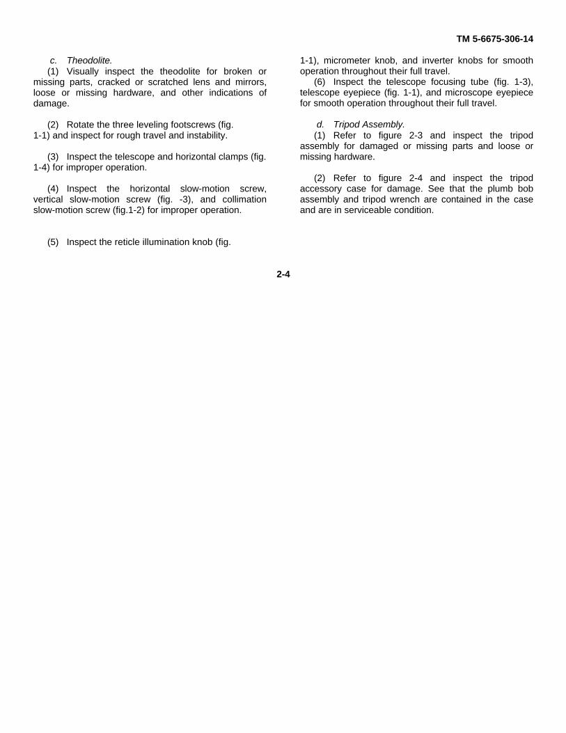
c. Theodolite.(1) Visually inspect the theodolite for broken or
missing parts, cracked or scratched lens and mirrors,loose or missing hardware, and other indications ofdamage.
(2) Rotate the three leveling footscrews (fig.1-1) and inspect for rough travel and instability.
(3) Inspect the telescope and horizontal clamps (fig.1-4) for improper operation.
(4) Inspect the horizontal slow-motion screw,vertical slow-motion screw (fig. -3), and collimationslow-motion screw (fig.1-2) for improper operation.
(5) Inspect the reticle illumination knob (fig.
1-1), micrometer knob, and inverter knobs for smoothoperation throughout their full travel.
(6) Inspect the telescope focusing tube (fig. 1-3),telescope eyepiece (fig. 1-1), and microscope eyepiecefor smooth operation throughout their full travel.
d. Tripod Assembly.(1) Refer to figure 2-3 and inspect the tripod
assembly for damaged or missing parts and loose ormissing hardware.
(2) Refer to figure 2-4 and inspect the tripodaccessory case for damage. See that the plumb bobassembly and tripod wrench are contained in the caseand are in serviceable condition.
2-4

TM 5-6675-306-14
Figure 2-3. Tripod assembly.
2-5

TM 5-6675-306-14
Figure 2-4. Tripod accessory case, unpacked view.
2-6

TM 5-6675-306-14
KEY to fig. 2-4:1. Tripod accessory case2. Tripod wrench3. Plumb bob
e. Accessory Case.(1) Inspect the accessory case for damage and
defective zipper and snaps. Make certain that the casecontains the components shown by figure 2-5.
(2) Inspect the telescope and microscope diagonaleyepieces and the telescope sunglass filter forscratches, cracks, and defective mounting.
(3) Inspect the lamp fittings for broken glass andcorroded or defective contacts.
2-7

TM 5-6675-306-14
Figure 2-5. Accessory case, unpacked view.2-8
TM 5-6675-306-14
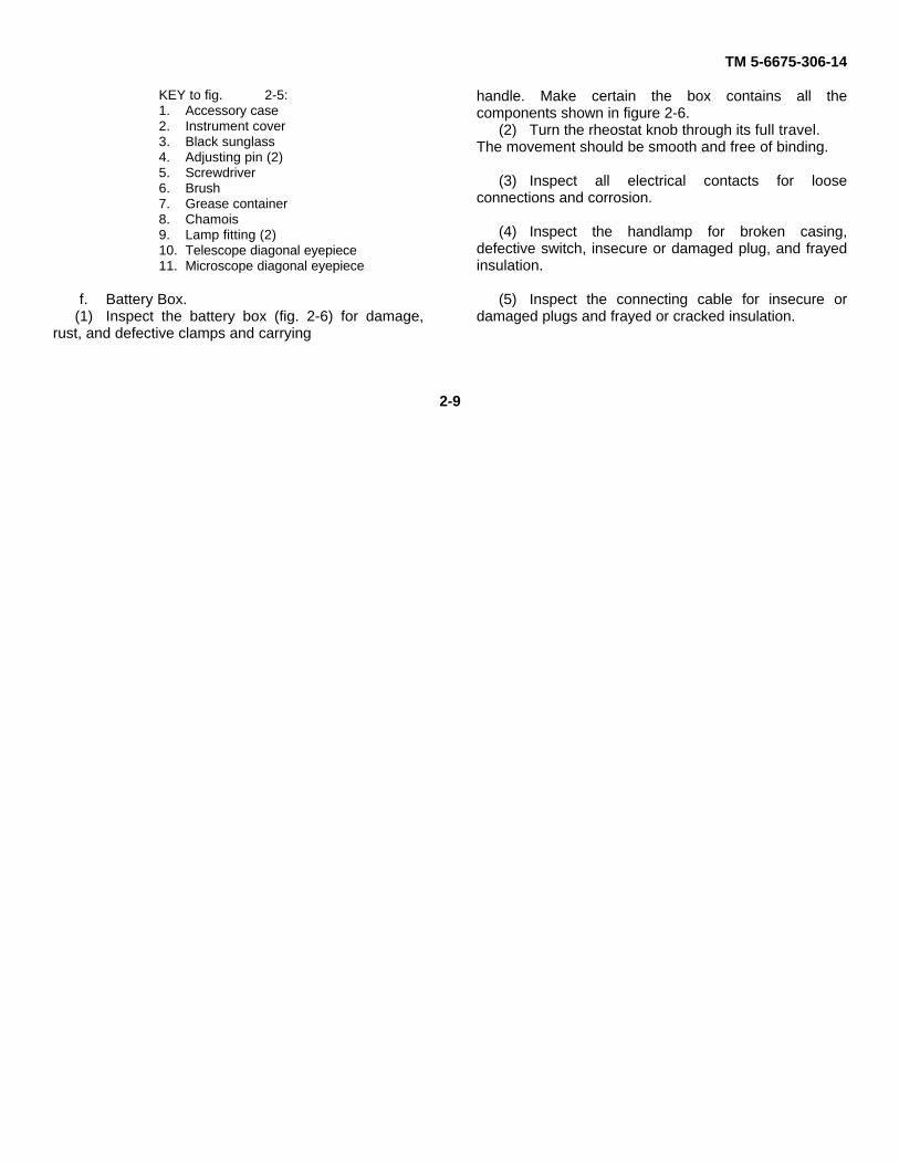
KEY to fig. 2-5:1. Accessory case2. Instrument cover3. Black sunglass4. Adjusting pin (2)5. Screwdriver6. Brush7. Grease container8. Chamois9. Lamp fitting (2)10. Telescope diagonal eyepiece11. Microscope diagonal eyepiece
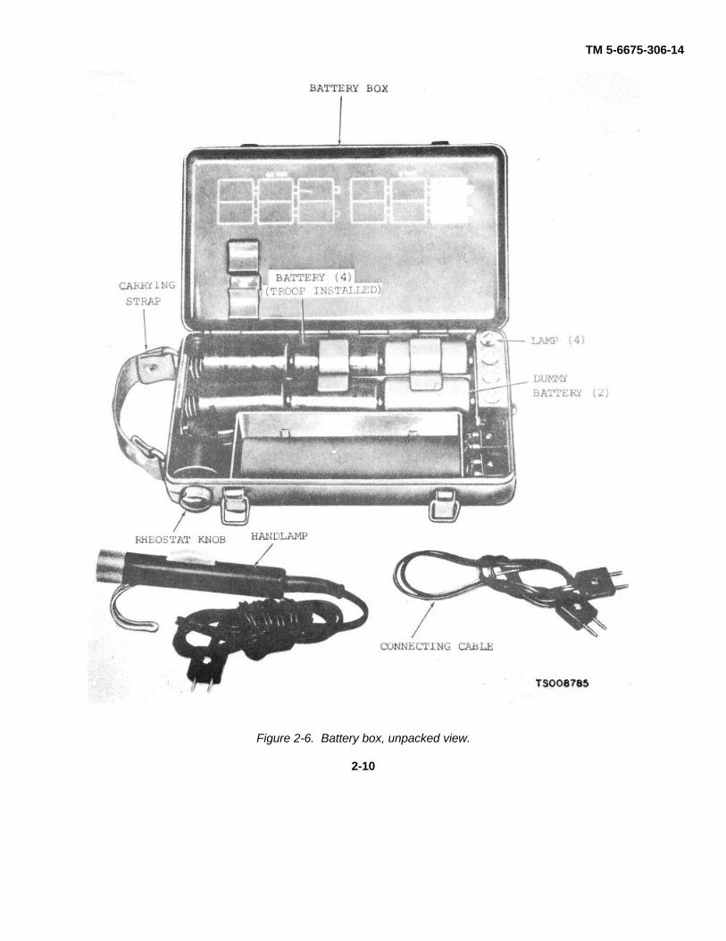
f. Battery Box.(1) Inspect the battery box (fig. 2-6) for damage,
rust, and defective clamps and carrying
handle. Make certain the box contains all thecomponents shown in figure 2-6.
(2) Turn the rheostat knob through its full travel.The movement should be smooth and free of binding.
(3) Inspect all electrical contacts for looseconnections and corrosion.
(4) Inspect the handlamp for broken casing,defective switch, insecure or damaged plug, and frayedinsulation.
(5) Inspect the connecting cable for insecure ordamaged plugs and frayed or cracked insulation.
2-9
TM 5-6675-306-14
Figure 2-6. Battery box, unpacked view.
2-10

TM 5-6675-306-14
g. Haversack. Inspect the haversack (fig. 2-7) fordamaged straps, insecure or defective buckles, tornpadding, and tears or cuts.
Figure 2-7. Haversack. 2-112-11

TM 5-6675-306-14
2-2. Installationa. Tripod. Refer to figure 2-8 and set up the tripod.b. Theodolite.
(1) Refer to figure 2-10 and remove theodolitecarrying case from shipping case.
(2) Refer to figure 2-1 and remove carrying casehood from base.
(3) Refer to figure 2-11 and remove the theodolitefrom the carrying case.
(4) Refer to figure 2-9 and install the theodolite onthe tripod.
2-12

TM 5-6675-306-14
Figure 2-8. Tripod and plumb bob, removal and installation.
2-13

TM 5-6675-306-14
Figure 2-9. Theodolite, removal and installation.
2-14

TM 5-6675-306-14
TSOO8789
Figure 2-10. Theodolite carrying case, removal and installation.
2-15
TM 5-6675-306-14
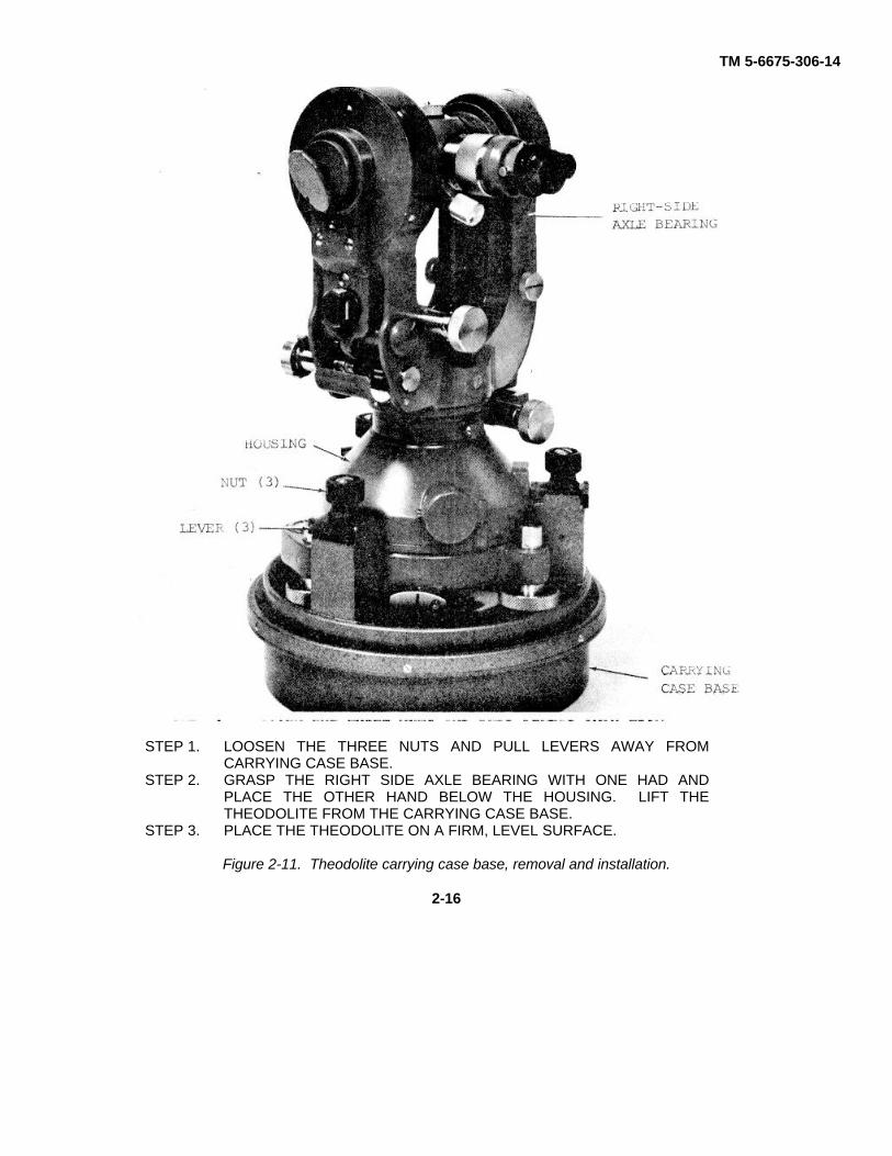
STEP 1. LOOSEN THE THREE NUTS AND PULL LEVERS AWAY FROMCARRYING CASE BASE.
STEP 2. GRASP THE RIGHT SIDE AXLE BEARING WITH ONE HAD ANDPLACE THE OTHER HAND BELOW THE HOUSING. LIFT THETHEODOLITE FROM THE CARRYING CASE BASE.
STEP 3. PLACE THE THEODOLITE ON A FIRM, LEVEL SURFACE.
Figure 2-11. Theodolite carrying case base, removal and installation.
2-16

TM 5-6675-306-14
2-3. Equipment Conversiona. General. During night or dark-day operation,
the reading circles are illuminated by installing theillumination system, which is contained in the batterybox and the accessory case. For high-angle andcelestial observations, the diagonal eyepieces and blacksunglass contained in the accessory case are installedon the telescope and microscope eyepieces.
b. Night or Dark-Day Operations. Refer to figure2-12 and install the illumination system.
c. High Angle Observations.(1) Remove the telescope and microscope
eyepieces (para 4-24).
(2) Remove the telescope and microscopeeyepieces from the accessory case (fig. 2-5).
(3) Refer to figure 2-13 and install thediagonal eyepieces.
WARNINGSevere eye damage can result fromperforming observations againstdirect sunlight without utilizing theblack sunglass (para 4-25).
2-17

TM 5-6675-306-14
NOTE: IF THE CONNECTING CABLE FROM THE BATTERY BOX TO THE THEODOLITE ISCONNECTED TO THE RECEPTACLE NEAREST THE CORNER OF THE BATTERY BOX,THE BRILLIANCE OF ILLUMINATION WITHIN THE THEODOLITE CAN BE CONTROLLED BYTURNING THE RHEOSTAT KNOB ON THE BATTERY BOX.
TS008791
Figure 2-12. Illumination system, removal and installation.
Change 1 2-18

TM 5-6675-306-14
Figure 2-13. Theodolite diagonal eyepieces, removal and installation.
2-19
TM 5-6675-306-14
Section II. MOVEMENT TO A NEW WORKSITE
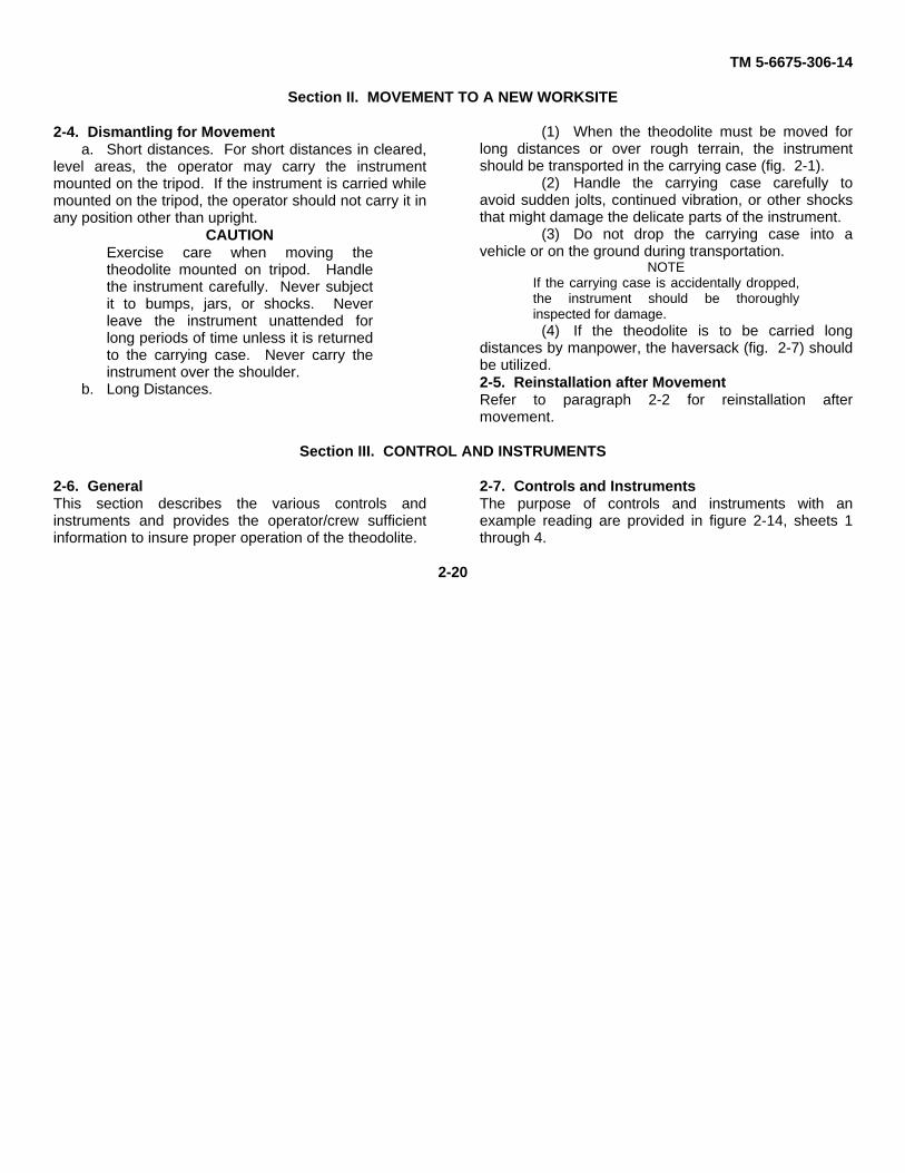
2-4. Dismantling for Movementa. Short distances. For short distances in cleared,
level areas, the operator may carry the instrumentmounted on the tripod. If the instrument is carried whilemounted on the tripod, the operator should not carry it inany position other than upright.
CAUTIONExercise care when moving thetheodolite mounted on tripod. Handlethe instrument carefully. Never subjectit to bumps, jars, or shocks. Neverleave the instrument unattended forlong periods of time unless it is returnedto the carrying case. Never carry theinstrument over the shoulder.
b. Long Distances.
(1) When the theodolite must be moved forlong distances or over rough terrain, the instrumentshould be transported in the carrying case (fig. 2-1).
(2) Handle the carrying case carefully toavoid sudden jolts, continued vibration, or other shocksthat might damage the delicate parts of the instrument.
(3) Do not drop the carrying case into avehicle or on the ground during transportation.
NOTEIf the carrying case is accidentally dropped,the instrument should be thoroughlyinspected for damage.
(4) If the theodolite is to be carried longdistances by manpower, the haversack (fig. 2-7) shouldbe utilized.2-5. Reinstallation after MovementRefer to paragraph 2-2 for reinstallation aftermovement.
Section III. CONTROL AND INSTRUMENTS
2-6. GeneralThis section describes the various controls andinstruments and provides the operator/crew sufficientinformation to insure proper operation of the theodolite.
2-7. Controls and InstrumentsThe purpose of controls and instruments with anexample reading are provided in figure 2-14, sheets 1through 4.
2-20

TM 5-6675-306-14
Figure 2-14. Controls and instruments (Sheet 1 of 4).
2-21

TM 5-6675-306-14
Figure 2-14. Controls and instruments (Sheet 2 of 4).
2-22

TM 5-6675-306-14
VERTICAL OR HORIZONTAL MICROMETER CIRCLE SCALECIRCLE SCALE
1 CALIBRATED IN NUMBERED1 CALIBRATED IN THREE-DIGIT AND UNNUMBERED LINES
INTERVALS TOTALING 360 FROM 0'0" to 9'59".DEGREES.
2 DISTANCE BETWEEN SINGLE- 2 DISTANCE BETWEEN NUM-DIGIT INTERVALS REPRESENTS BERED LINES REPRESENTSTEN MINUTES 10 SECONDS. DISTANCE BE-
3 USED TO MEASURE ANGLES IN TWEEN UNNUMBERED LINESDEGREES TO NEAREST 10 REPRESENTS ONE SECOND.MINUTES 3 USED TO MEASURE MINUTES
AND SECONDS ON BOTHVERTICAL AND HORIZONTALSCALES.
Figure 2-14. Controls and instruments (Sheet 3 of 4).
2-23

TM 5-6675-306-14
Figure 2-14. Controls and instruments (Sheet 4 of 4).
2-24

TM 5-6675-306-14
Section IV. OPERATION UNDER USUAL CONDITIONS
2-8. Generala. The instructions in this section are published for
the information and guidance of personnel responsiblefor operation of the theodolite.
b. The operator must know how to PERFORMevery operation of which the theodolite is capable Thissection gives instructions on handling and preparationfor operation of the theodolite basic motions,adjustments, and on coordinating the basic motions toperform the specific tasks for which the equipment isdesigned. Since nearly every job presents a differentproblem, the operator may have to vary givenprocedures to fit the individual job.2-9. Preparation for Operation
a. General. This paragraph describes allpreventive maintenance checks and services and allinstrument adjustments necessary to prepare thetheodolite for operation. Instrument adjustments bringthe theodolite into proper operating condition withrespect to the interrelationship of its parts and are notnormally made in the field.
b. Preventive Maintenance Checks and Services.Perform the daily preventive maintenance checks andservices (para 3-5).
c. Plate Level. Refer to figure 2-15 and adjust theplate level.
d. Collimation Slow-Motion Screw. Refer to figure2-16 and adjust the collimation slow-motion screw.
e. Vertical Slow-Motion Screw. Refer to figure 2-16 and adjust the vertical slow-motion screw.
f. Horizontal Slow-Motion Screw. Refer to figure2-16 and adjust the horizontal slow-motion screw.
g. horizontal Circle Drive Knob. Refer to figure 2-17 and adjust the horizontal circle drive knob.
h. Footscrews. Refer to figure 2-18 and adjust thefootscrews.
i. Horizontal Collimation Error Adjustment Referto figure 2-19 and adjust the theodolite horizontalcollimation error.
j. Vertical Collimation Error Adjustment. Refer tofigure 2-20 and adjust the theodolite vertical collimationerror.
k. Circular Level. Refer to figure 2-21 and adjustthe circular level.
l. Optic Plummet. Refer to figure 2-22 and adjustthe optical plummet.
2-25

TM 5-6675-306-14
STEP 1. BRING PLATE LEVEL BUBBLE TO AS NEARCENTER AS POSSIBLE.
STEP 2. WITH THE THEODOLITE IN THIS POSITION,CORRECT ONE-HALF OF THE BUBBLE ERROR BYTURNING THE FOOTSCREW.
STEP 3. USING THE ADJUSTING PIN (FIG. 2-5), TURN THEPLATE LEVEL ADJUSTING SCREW TO CORRECTTHE OTHER HALF OF THE ERROR.
STEP 4. REPEAT THE ABOVE STEPS UNTIL THE BUBBLEREMAINS CENTERED REGARDLESS OF THEPOSITION TO WHICH THE THEODOLITE ISTRAVERSED.
Figure 2-15. Plate level adjustment.
2-26

TM 5-6675-306-14
Figure 2-16. Collimation, vertical and horizontal slow-notion screws, adjustment.
2-27

TM 5-6675-306-14
STEP 1. OPEN THE KNOB COVER.STEP 2. TURN THE DRIVE KNOB UNTIL THE THREE
SCREWS CAN BE SEEN THROUGH THE HOLES INTHE KNOB.
STEP 3. LOOSEN THE THREE SCREWS JUST ENOUGH TOMOVE THE -KNOB MOVE THE KNOB UP ORDOWN UNTIL IT TURNS SMOOTHLY WITHOUTWHIPLASH.
STEP 4. TIGHTEN THE THREE SCREWS AND CLOSE THEKNOB COVER.
Figure 2-17. Horizontal circle drive knob, adjustment.
2-28

TM 5-6675-306-14
Figure 2-18. Footscrews, adjustment.
2-29
TM 5-6675-306-14
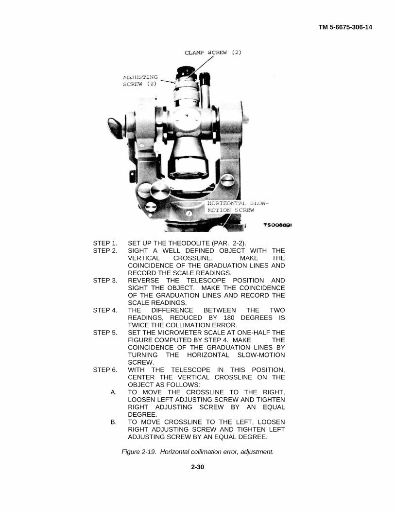
STEP 1. SET UP THE THEODOLITE (PAR. 2-2).STEP 2. SIGHT A WELL DEFINED OBJECT WITH THE
VERTICAL CROSSLINE. MAKE THECOINCIDENCE OF THE GRADUATION LINES ANDRECORD THE SCALE READINGS.
STEP 3. REVERSE THE TELESCOPE POSITION ANDSIGHT THE OBJECT. MAKE THE COINCIDENCEOF THE GRADUATION LINES AND RECORD THESCALE READINGS.
STEP 4. THE DIFFERENCE BETWEEN THE TWOREADINGS, REDUCED BY 180 DEGREES ISTWICE THE COLLIMATION ERROR.
STEP 5. SET THE MICROMETER SCALE AT ONE-HALF THEFIGURE COMPUTED BY STEP 4. MAKE THECOINCIDENCE OF THE GRADUATION LINES BYTURNING THE HORIZONTAL SLOW-MOTIONSCREW.
STEP 6. WITH THE TELESCOPE IN THIS POSITION,CENTER THE VERTICAL CROSSLINE ON THEOBJECT AS FOLLOWS:
A. TO MOVE THE CROSSLINE TO THE RIGHT,LOOSEN LEFT ADJUSTING SCREW AND TIGHTENRIGHT ADJUSTING SCREW BY AN EQUALDEGREE.
B. TO MOVE CROSSLINE TO THE LEFT, LOOSENRIGHT ADJUSTING SCREW AND TIGHTEN LEFTADJUSTING SCREW BY AN EQUAL DEGREE.
Figure 2-19. Horizontal collimation error, adjustment.
2-30

TM 5-6675-306-14
STEP 1. REFER TO FIGURE 2-19 AND CORRECTHORIZONTAL COLLIMATION IF NECESSARY.
STEP 2. SIGHT A WELL DEFINED OBJECT WITH THE'HORIZONTAL CROSSLINE. COINCIDE THECOLLIMATION LEVEL BUBBLE BY TURNING THECOLLIMATION; SLOW--MOTION SCREW. MAKETHE COINCIDENCE OF THE GRADUATION LINESAND RECORD THE SCALE READINGS.
STEP 3. REVERSE THE TELESCOPE POSITION, SIGHTTHE OBJECT. COINCIDE THE COLLIMATIONLEVEL BUBBLE. MAKE THE COINCIDENCE OFTHE GRADUATION LINES AND RECORD THESCALE READINGS.
STEP 4. THE TOTAL OF THE -10 READINGS, REDUCED BY360 DEGREES IS TWICE THE COLLIMATIONERROR.. COMPUTE THE ZENITH DISTANCE ANDSET THE MICROMETER SCALP, AT THECORRECT READING.
STEP S. MAKE THE COINCIDENCE OF THE GRADUATIONLINES.
STEP 6. COINCIDE THE COLLIMATION LEVEL BUBBLE BYLOOSENING ONE ADJUSTING SCREW ANDTIGHTENING THE OTHER ADJUSTING SCREW BYAN EQUAL DEGREE.
Figure 2-20. Vertical collimation error, adjustment.
2-31

TM 5-6675-306-14
STEP 1. REFER TO PARAGRAPH 2-10 AND LEVEL THETHEODOLITE.
STEP 2. IF THE CIRCULAR LEVEL IS NOT CENTERED INTHE VIAL, THE CIRCULAR LEVEL IS OUR OFADJUSTMENT. TIGHTEN OR LOOSEN THETHREE ADJUSTING SCREWS TO BRING THELEVEL BUBBLE TO CENTER.
STEP 2. NONE OF THE THREE ADJUSTING SCREWSSHOULD BE TIGHTENED ALL THE WAY. THEYSHOULD FLOAT ON THE ADJUSTING SPRINGS.
Figure 2-21. Circular level, adjustment.
2-32

TM 5-6675-306-14
STEP 1. REFER TO PARAGRAPH 2-2 AND SET UP THETHEODOLITE.
STEP 2. OBSERVE STATION POINT THROUGH OPTICALPLUMMET EYEPIECE. IF STATION POINT IS NOTCENTERED IN THE EYEPIECE CIRCULAR MARKS,USE ADJUSTING PIN (FIG. 2-5) TO TURN THETWO HORIZONTAL ADJUSTING SCREWS FORLATERAL ALIGNMENT. FOR VERTICALALIGNMENT, LOOSEN CHECK NUT AND TURNVERTICAL ADJUSTING SCREW.
STEP 3. WHEN THE STATION POINT IS CENTERED IN THEEYEPIECE CIRCULAR MARKS, TIGHTEN THECHECK NUT.
Figure 2-22. Optical plummet, adjustment.
2-10. Operation of Theodolite c. Install the diagonal eyepieces as necessarya. Set up the theodolite on the tripod (para 2- (para 2-3).
2). d. Install the telescope eyepiece black sunglassb. If necessary, install the illumination system as necessary (para 4-24).
(para 2-3) e. Perform the daily preventive maintenanceNOTE services (para 3-5).
To operate the illumination system, turn the f. Refer to figure 2-23 and level the theodolite.rheostat knob until desired brilliance is obtained.Place the hand light switch in the ON position.
2-33

TM 5-6675-306-14
WARNINGSevere eye damage can result fromperforming observations against directsunlight without utilizing the telescopeblack sunglass.
g. Focus the telescope as follows: (1) Direct thetelescope toward a uniformly light background. Adjustthe telescope eyepiece (fig. 1-1) until the crosslines aresharp and black.
NOTEObserve the setting on the eyepiece(fig 1-1) This setting will remainconstant for the same observer butwill vary for other observers.
(2) Adjust the telescope focusing tube (fig. 1-
3) to bring into view a clear image of the object beingsighted.
h. The horizontal and vertical circle reading scalesare both observed through the microscope eyepiece (fig.1-1). When the line of the inverter knob is in ahorizontal position, the horizontal circle image appearsin the upper window (fig. 214). When the inverter knobis turned with the line in the vertical position, the verticalcircle image appears in the upper window.Simultaneously with either of the circle images, theimage of the micrometer scale is always visible in thelower window (fig. 2-14).
2-34

TM 5-6675-306-14
STEP 1. UNLOCK THE HORIZONTAL CLAMP. ROTATE THEU-STANDARD UNTIL THE PLATE LEVEL ISPARALLEL TO A LINE JOINING ANY TWOFOOTSCREWS. LOCK THE CLAMP.
STEP 2. TURN THE TWO FOOTSCREWS THAT AREPARALLEL WITH THE PLATE LEVELSIMULTANEOUSLY, BUT IN OPPOSITEDIRECTIONS UNTIL THE LEVEL BUBBLE ISCENTERED.
STEP 3. UNLOCK THE HORIZONTAL CLAMP. ROTATE THEU-STANDARD 90° AND LOCK THE CLAMP. TURNTHE THIRD FOOTSCREW UNTIL THE LEVELBUBBLE IS CENTERED.
STEP 4. UNLOCK THE HORIZONTAL CLAMP. ROTATE THEU-STANDARD 180O AND LOCK THE CLAMP.TURN THE SAME FOOTSCREW AS IN STEP 3 ANDREMOVE ONE HALF OF ANY BUBBLEDISPLACEMENT THAT MAY EXIST.
NOTE: IF AFTER STEP 4 THE PLATE BUBBLE IS MORETHAN TWO DIVISIONS FROM CENTRALITY, THECORRECTION IS MADE BY MEANS OF THE PLATELEVEL ADJUSTING SCREW. REFER TOPARAGRAPH 2-9.
Figure 2-23. Theodolite leveling.
2-35

TM 5-6675-306-14
Section V. OPERATION UNDER UNUSUAL CONDITIONS
2-11. Operation in Extreme Cold (Below 0°F.) (-18°C.)
With proper precautions and servicing, the theodolitecan be used in extreme cold. Its use is limited only bythe endurance of operating personnel and conditionsaffecting visibility. The theodolite should be kept out-of-doors or in unheated buildings for short periods ofnonuse. Extreme temperature changes will induceinternal stresses affecting accuracy and lenses, andprisms may become fogged. Theodolites to be usedunder conditions of extreme cold should be cleaned,and all lubricants should be removed before theinstruments are used.
CAUTIONAvoid subjecting the theodolite tosudden changes in temperature.
2-12. Operation in Extreme HeatOperation of the theodolite in extreme heat and underthe direct rays of the sun can cause internal stressesand distortion in the instrument and produce poorsightings because of heat waves. If possible, thetheodolite and the instrument man should be protectedfrom the direct sunlight by an umbrella or other suitablemeans. Under these conditions, shorter sightings willdecrease the amount of sighting errors. Takingsightings during early morning and late evening will alsominimize error magnitude. The use of suitable darkglasses by the instrument man will reduce eyestrain andfatigue. If the theodolite is kept in a cool storage place,it should be removed from storage in sufficient timebefore use to allow the temperature of the metal toapproach that of the outside air.2-13. Operation in Dusty or Sandy AreasSpecial care must be given instruments which are beingused in dusty or sandy areas, since both dust and sandare highly abrasive. If dust and sand are allowed toremain on threaded or sliding surfaces, moving parts ofthe theodolite will soon bind and the instrument willbecome inaccurate or inoperable. The theodolite shouldbe brushed frequently and carefully wiped clean. Beextremely careful not to scratch lens and prism surfacesduring cleaning operations. Always protect theinstrument from blowing dust and sand. Place aprotective cover over the theodolite when it is not in use.
2-14. Operation under Rainy or Humid ConditionsIn humid areas, a slight lowering of the temperature willcause condensation of moisture and fogging of lensesand prisms. Internal fogging can usually be removed byplacing the theodolite in a warm, dry place. Corrosioncaused by high humidity can be partially eliminated byusing warm, dry storage areas and desiccants. Afteruse, dry the instrument thoroughly with a soft, lint-freecloth.2-15. Operation in Salt Water AreasWhen operating the theodolite in salt water areas, wipethe instrument frequently with a soft, clean cloth. If thetheodolite is exposed to direct salt spray, it should becleaned thoroughly and should be returned to aninstrument shop for overhauling as soon as possible.Cleaning intervals should be shortened considerably fortheodolites subjected to salt air exposure. Salt is highlycorrosive to metal.2-16. Operation in SnowVisibility is sharply reduced while snow is falling. Whentaking sightings after a snowfall, the use of suitable darkglasses by the instrument man will reduce eyestrain andfatigue. If snow conditions are accompanied by extremecold (below 0° F.) (-18'C.), refer to paragraph 2-11.2-17. Operation in MudMud is highly abrasive and if allowed to remain onthreaded or sliding surfaces, moving parts of thetheodolite will soon bind and the instrument will becomeinaccurate or inoperable. The theodolite should becarefully wiped clean. Be extremely careful not toscratch lens and prism surfaces during cleaningoperations. Place a protective cover over the theodolitewhen not in use. When the tripod is set up on muddyground, leveling is extremely important and should bechecked frequently. Anchor tripod legs firmly to avoidslippage which will cause incorrect readings.2-18. Operation at High AltitudesNo special procedures are required to operate thetheodolite at high altitudes.
2-36

TM 5-6675-306-14
CHAPTER 3
OPERATOR/ CREW MAINTENANCE INSTRUCTIONS
Section I. BASIC ISSUE ITEMS LIST AND ITEMS TROOP INSTALLED ORAUTHORIZED LIST
3-1. Basic Issue Items and Items Troop Installedor Authorized
Tools, equipment and repair parts issued with troop
installed or authorized for the theodolite are listed in thebasic issue items list and items troop installed orauthorized list, Appendix B.
Section II. LUBRICATION INSTRUCTIONS
3-2. Generala. This section contains a lubrication chart and
instructions which are supplemental to, and notspecifically covered in the lubrication chart. Refer tofigure 3-1 for the lubrication chart.
b. All moving parts of the theodolite, both smoothand threaded surfaces, are fitted within extremely finetolerances. For this reason, most parts of the theodoliteare cleaned prior to lubrication. Any attempt tolubricate the theodolite without first cleaning it, mayresult in damage to the instrument. Only thoselubricants approved for use on the theodolite will beused. No lubrication will be performed in the fieldunless specifically called for.3-3. Detailed Lubrication Information
a. Care of Lubricants. Special care should betaken to see that all surveying instrument lubricants arekept absolutely free from contamination by any foreignsubstance. Containers must be stored in a clean, dry
place and wiped free of dirt or dust before they areopened. All lids or bottle tops must be airtight.
b. Lubricants. No lubricants other than thoseapproved for use on the theodolite will be stocked.Approved lubricants are noncorrosive and highly refinedand must be free from all paint removing ingredients.The following lubricants are approved for use on thistheodolite:
(1) OCW; oil, clock and watch.(2) DM; grease, aircraft and instrument.
c. Lubrication Procedure. Cleaning and lubricationservices, which require partial or complete disassemblyof the instrument, must be performed in the dust-freeatmosphere of an instrument repair shop and only byqualified personnel. Disassembling the instrumentunder other conditions, especially where dust might filterinto recesses, will do more harm than good. Since thelubricants must be applied sparingly, never use acontainer with a spout, such as an oil can, to apply oil onparts or into assemblies.
3-1

TM 5-6675-306-14
Figure 3-1. Lubrication Chart-Sheet 1 of 2 ).
3-2

TM 5-6675-306-14
Figure 3-1. Lubrication Chart (Sheet 2 of 2 ).
3-3

TM 5-6675-306-14
Section III. PREVENTIVE MAINTENANCE CHECKS AND SERVICES
3-4. GeneralTo insure that the theodolite is ready for operation at alltimes, it must be inspected systematically so thatdefects may be discovered and corrected before theyresult in serious damage or failure. The necessarypreventive maintenance checks and services to beperformed are listed and described in paragraph 3-5.The item numbers indicate the sequence of minimuminspection requirements. Defects discovered duringoperation of the unit shall be noted for future correction,to be made as soon as operation has ceased. Stopoperation immediately if a deficiency is noted duringoperation which would damage the equipment if
operation were continued. All deficiencies andshortcomings will be recorded, together with thecorrective action taken, on DA Form 2404 (EquipmentInspection and Maintenance Worksheet) at the earliestpossible opportunity.3-5. Preventive Maintenance Checks and ServicesThis paragraph contains a tabulated listing of operator'speriodic (daily) preventive maintenance checks andservices. The sequence numbers are listedconsecutively and indicate the minimum requirementsfor daily (D) and weekly (W) preventive maintenance,respectively. Refer to table 3-1 for the preventivemaintenance checks and services.
Table 3-1. Operator/Crew Preventive Maintenance Checks and Services
D-Daily W-WeeklyTime required: 0.5 Time required: 0.1
Interval ITEM TO BE INSPECTED WORKand PROCEDURE TIME
Sequence No (M/H)
D W
1 HAVERSACKClean dirty haversack 0.1
2 ACCESSORY CASEClean accessory case Check for missing components 0.1
3 TRIPOD ACCESSORY CASECheck for missing components 0.1
4 BATTERY BOXReplace defective batteries or missing spare lamps Check handlamp for proper operation 0 1
1 TRIPODClean dirty tripod 0.1
5 CARRYING CASECheck dessicant for proper color 0.1
Section IV. TROUBLESHOOTING
3-6. Scopea. This section contains troubleshooting or
malfunction information and tests for locating andcorrecting most of the troubles which may develop in thetheodolite. Each malfunction or trouble symptom for anindividual component, unit, or system is followed by alist of tests or inspections necessary for you todetermine probable causes and suggested correctiveactions for you to remedy the malfunction.
b. This manual cannot list all possible malfunctionsthat may occur or all tests, or inspections, and correctiveactions. If a malfunction is not listed or is not corrected
by listed corrective actions, you should notify higherlevel maintenance.
c. Table 3-2 lists the common malfunctions thatyou may find during the operation or maintenance of thetheodolite or its components.You should perform the tests, inspections and correctiveactions in the order listed.
NOTEIf you have a malfunction which is notlisted in this table. notify the nexthigher level of maintenance.
3-4
TM 5-6675-306-14
Table 3-2. Troubleshooting
MALFUNCTIONTEST OR INSPECTION
CORRECTIVE ACTION
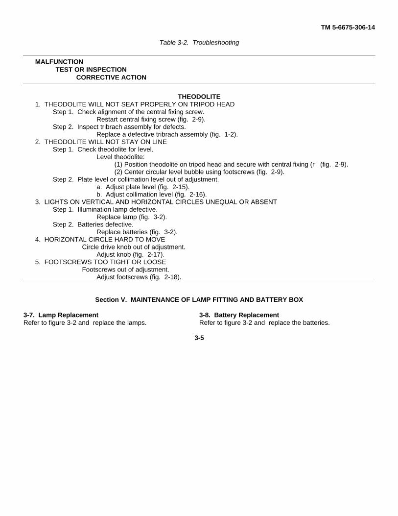
THEODOLITE1. THEODOLITE WILL NOT SEAT PROPERLY ON TRIPOD HEAD
Step 1. Check alignment of the central fixing screw.Restart central fixing screw (fig. 2-9).
Step 2. Inspect tribrach assembly for defects.Replace a defective tribrach assembly (fig. 1-2).
2. THEODOLITE WILL NOT STAY ON LINEStep 1. Check theodolite for level.
Level theodolite:(1) Position theodolite on tripod head and secure with central fixing (r (fig. 2-9).(2) Center circular level bubble using footscrews (fig. 2-9).
Step 2. Plate level or collimation level out of adjustment.a. Adjust plate level (fig. 2-15).b. Adjust collimation level (fig. 2-16).
3. LIGHTS ON VERTICAL AND HORIZONTAL CIRCLES UNEQUAL OR ABSENTStep 1. Illumination lamp defective.
Replace lamp (fig. 3-2).Step 2. Batteries defective.
Replace batteries (fig. 3-2).4. HORIZONTAL CIRCLE HARD TO MOVE
Circle drive knob out of adjustment.Adjust knob (fig. 2-17).
5. FOOTSCREWS TOO TIGHT OR LOOSEFootscrews out of adjustment.
Adjust footscrews (fig. 2-18).
Section V. MAINTENANCE OF LAMP FITTING AND BATTERY BOX
3-7. Lamp Replacement 3-8. Battery ReplacementRefer to figure 3-2 and replace the lamps. Refer to figure 3-2 and replace the batteries.
3-5

TM 5-6675-306-14
Figure 3-2. Lamp and battery, removal and installation.
Change 1 3-6

TM 5-6675-306-14
CHAPTER 4
ORGANIZATIONAL MAINTENANCE INSTUCTIONS
Section I. SERVICE UPON RECEIPT OF EQUIPMENT
4-1. Service Upon Receipt of EquipmentRefer to paragraph 2-1 for instructions pertaining to service upon receipt of equipment.
Section II. MOVEMENT TO A NEW WORKSITE
4-2. Movement to a New WorksiteRefer to paragraphs 2-4 and 2-5 for instructions pertaining to movement to a new worksite.
Section III. REPAIR PARTS, SPECIAL TOOLS AND EQUIPMENT
4-3. Tools and EquipmentTools, equipment, and repair parts issued with troopinstalled, or authorized for the theodolite are listed in thebasic issue items list and items troop installed orauthorized list, Appendix B.
4-4. Special Tools and EquipmentThe special tools required to perform organizationalmaintenance on the theodolite are listed in table 4-1.
References and illustrations indicating the use of thesetools are listed in the table. The five-digit numberpreceding the stock number is the Federal Supply CodeNumber for the manufacturer of the tool(s). No specialequipment is required by organizational maintenancepersonnel for performing maintenance on the theodolite.
Table 4-1. Special Tools
Item NSN or Part No. Reference UseFigure Paragraph
Pin, adjusting (89905)* 6675-00-353-4103 2-5 2-9 Adjust theodolite adjusting screws.Wrench, tripod (89905)* 5120-00-378-9520 2-4 2-2 Tripod leg adjustment, removal,
and installation .
4-5. Maintenance Repair Parts Repair parts andare listed and equipment. illustrated in the repair parts
and special tools list, TM 5-6675-306-24P, coveringorganizational maintenance for this equipment.
Section IV. LUBRICATION INSTRUCTIONS
4-6. Lubrication InstructionsRefer to paragraphs 3-2 and 3-3 for lubrication instructions.
4-1

TM 5-6675-306-14
Section V. PREVENTIVE MAINTENANCE
4-7. GeneralTo insure that the theodolite is ready for operation at alltimes, it must be inspected systematically so thatdefects may be discovered and corrected before theyresult in serious damage or failure. The necessarypreventive maintenance checks and services to beperformed are listed and described in paragraph 4-8.The item numbers indicate the sequence of minimuminspection requirements. Defects discovered duringoperation of the unit shall be noted for future correction,to be made as soon as operation has ceased. Stopoperation immediately if a deficiency is noted duringoperation which would damage the equipment ifoperation were continued. All deficiencies andshortcomings will be recorded,
together with the corrective action taken, on DA Form2404 (Equipment Inspection and MaintenanceWorksheet) at the earliest possible opportunity.4-8. Preventive Maintenance Checks andServicesThis paragraph contains a tabulated listing oforganizational periodic preventive maintenance checksand services. The item numbers are listedconsecutively and indicate the sequence of minimumrequirements. A quarterly interval is equal to 3 calendarmonths, or 250 hours of operation, whichever occursfirst. Refer to table 4- 2 for the preventive maintenancechecks and services.
Table 4-2. Organizational Preventive Maintenance Checks and ServicesQ - QuarterlyTotal man-hours required: 0.9Sequence ITEMS TO BE INSPECTED Worknumber PROCEDURE time
(M/H)
1 HAVERSACKClean dirty haversack. Replace defective haversack. 0.1
2 ACCESSORY CASEReplace missing or defective components 0.1
3 TRIPOD ACCESSORY CASEReplace missing or defective components. 0.1
4 BATTERY BOXReplace defective batteries. Replace missing spare lamps. Replace defective handlamp. 0.1
5 TRIPODRepair or replace defective tripod. 0.2
6 CARRYING CASEReplace discolored dessicant. Replace defective carrying case.
7 THEODOLITEClean dirty lenses, mirrors and level vials. Check eyepieces adjusting and clamping 0.2. knobs of movement for freedom.
Section VI. TROUBLESHOOTING
4-9. Scopea. This section contains troubleshooting or
malfunction information and tests for locating andcorrecting most of the troubles which may develop in thetheodolite. Each malfunction or trouble symptom for anindividual component, unit, or system is followed by alist of tests or inspections necessary for you todetermine probable causes and suggested correctiveactions for you to remedy the malfunction.
b. This manual cannot list all possible malfunctionsthat may occur or all tests or inspections, and correctiveactions. If a malfunction is not listed, or is not corrected
by listed corrective actions, you should notify higherlevel maintenance.
c. Table 4-3 lists the common malfunctions thatyou may find during the operation or maintenance of thetheodolite or its components. You should perform thetests/inspections and corrective actions in the orderlisted.
NOTEIf you have a malfunction which is notlisted in this table, notify the next higherlevel of maintenance.
4-2

TM 5-6675-306-14Table 4-3. Troubleshooting
MALFUNCTIONTEST OR INSPECTION
CORRECTIVE ACTION
THEODOLITE1. THEODOLITE WILL NOT SEAT PROPERLY ON TRIPOD HEAD
Step 1. Check alignment of the central fixing screw.Restart central fixing screw (fig. 2-9).
Step 2. Inspect tribrach assembly for defects.Replace a defective tribrach assembly (fig. 1-2).
Step 3. Tripod head defective.Replace a defective head (fig. 4-6).
2. THEODOLITE WILL NOT STAY ON LINEStep 1. Check theodolite for level.
Level theodolite.(1) Position theodolite on tripod head and secure with central fixing screw (fig. 2-(9).(2) Center circular level bubble using footscrews (fig. 2-9).
Step 2. Plate level or collimation level out of adjustment.a. Adjust plate level (fig. 2-15).b. Adjust collimation level (fig. 2-16).
3. LIGHTS ON VERTICAL AND HORIZONTAL CIRCLES UNEQUAL OR ABSENTStep 1. Illumination lamp defective.
Replace lamp (fig. 3-2).Step 2. Batteries defective.
Replace batteries (fig. 3-2).Step 3. Horizontal or vertical circle illuminating mirror defective.
Replace mirror-(fig. 4-4).4. TRIPOD LEG WILL NOT LOCK IN POSITION
Leg clamping screws loose,Tighten or replace screws (fig. 2-8).
5. HORIZONTAL CIRCLE HARD TO MOVECircle drive knob out of adjustment.
Adjust knob (fig. 2-17).6. FOOTSCREWS TOO TIGHT OR LOOSE
Footscrews out of adjustment.Adjust footscrews (fig. 2-18).
7. TELESCOPE TURNS TOO HARD OR TOO EASILYTelescope clamp not properly adjusted.
Adjust clamp (fig. 2-14).
Section VII. CARRYING CASE AND HAVERSACK
4-10. GeneralThe carrying case for theodolite is composed of themetal hood and base. The carrying case provides aconvenient means of carrying the theodolite in the fieldand serves as a dustproof and mositureproof containerfor the instrument when it is in storage. The base has arecess in the bottom which houses the desiccantcontainer. The haversack is used to carry the theodolitewhen the use of the carrying case is impractical.4-11. Carrying Case
a. Hood.(1) Removal. Remove the hood (para 2-2).(2) Disassembly. Refer to figure 4-1 and
disassemble the hood.(3) Cleaning, inspection, and repair.
WARNING
Dry cleaning solvent, P-D-680, used
to clean parts is potentially dangerous topersonnel and property. Avoid repeatedand prolonged skin contact. Do not usenear open flame or excessive heat.Flash point of solvent is 100 0 F.-138 °F. (38 C.-59 ° C.)
(a) Clean all metal parts with an approved cleaningsolvent and dry thoroughly.
(b) Clean the carrying strap with saddle soap.(c) Inspect the strap for cracks, breaks, and cuts.
Inspect for worn mounting holes and deterioration due toage. Inspect for enlarged mounting holes.
(d) Inspect the lock pins for burrs and wear. Inspectthe locking levers and lever springs for burrs, bends,and crack. Inspect the hood for (dents, cracks, andholes. Inspect the bottom rim for out-of-round.
4-3

TM 5-6675-306-14
(f) Remove all burrs from the lock pins, lockinglevers, and lever springs. Straighten dents. Remove alltraces of rust and repaint where necessary.
(g) Straighten dents or bends in the hood. Seal allcuts or holes in the hood. Repaint where necessary.
(h) Replace all defective parts that cannot berepaired.
(4) Reassembly. Refer to figure 4-1 andreassemble the hood.
(5) Installation. Install the hood (fig. 2-1).b. Base.
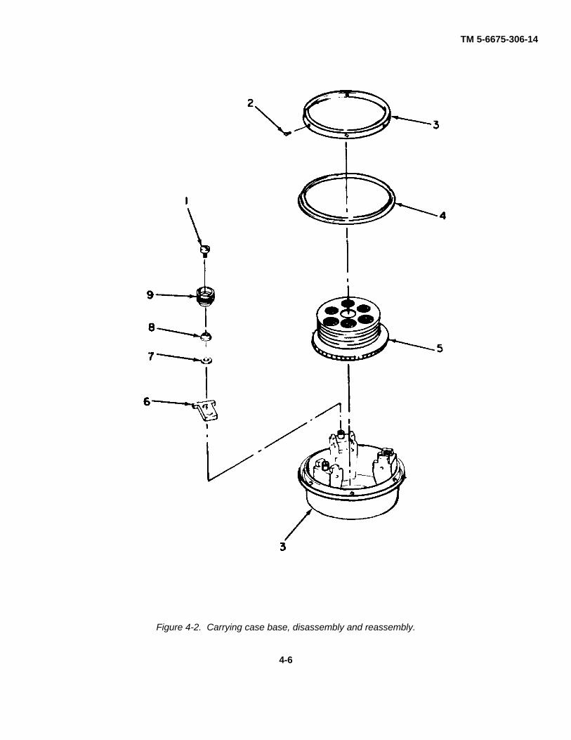
(1) Removal. Remove the base (fig. 2-11i.(2) Disassembly. Refer to figure 4-2 and
disassemble the base.(3) Cleaning, inspection, and repair.
WARNINGDry cleaning solvent, P-D-680, used toclean parts is potentially dangerous topersonnel and property. Avoid repeatedand prolonged skin contact. Do not usenear open flame or excessive heat.Flash point of solvent is 100° F.-138° F.(38°C.-59°C.)
(a) Clean all metal parts with an approved cleaningsolvent and dry thoroughly. Brush threaded surfacesfree of any foreign matter. Wipe the rubber gasket cleanwith a soft cloth.
(b) Inspect all threaded surfaces for worn
or damaged threads. Inspect the lever nuts, levers, andwashers for burrs and worn surfaces.
(c) Inspect the base for cracks and a brokencasting. Inspect the collar of base for bends, breaks, andout-of-round.
(d) Inspect the rubber gasket for damage orhardening because of age or excessive heat.
(e) Remove all burrs from the base, levers, levernuts, and collar of base.Straighten bends in the collar ofbase and washers. Replace all defective parts.
(f) Inspect the sections of the desiccant containerfor bends, breaks, and damaged threads
(g) Inspect the desiccant for color. Serviceabledesiccant is blue in color. Pink desiccant indicatesmoisture saturation, and the desiccant must bedehydrated or replaced.
(h) Replace the desiccant or container asnecessary.
(4) Reassembly. Refer to figure 4-2 andreassemble the base.
(5) Installation. Refer to fig. 2-2. Install thetheodolite on the carrying case base.
KEY to fig. 4-1:1. Leather strap 4. Lock spring (2)2 Metal hood 5. Lock lever (213 Lock pin (4) 6. Rivet (4)
4-4

TM 5-6675-306-14
Figure 4-1. Carrying case hood, disassembly and reassembly.
4-5
TM 5-6675-306-14
Figure 4-2. Carrying case base, disassembly and reassembly.
4-6
TM 5-6675-306-14
KEY to fig. 4-2:1. Screw (31 6. Lever J3)2. Screw (61 7. Washer (3)3. Base 8. Spring washer 13)4. Rubber gasket 9. Nut (3)5 Desiccant container
4-12. Haversacka. General. The haversack (fig. 2-7) is used for
carrying the theodolite when it is impractical tocarry the unit using the carrying case. The
theodolite in its carrying case is strapped in thehaversack, which in turn, is carried on the operator'sback.
b. Cleaning and Inspection.(1) Brush the haversack free of dust and dirt.
Clean the straps with saddle soap.(2) Inspect the haversack for damage and defects
that would render it unserviceable. Repair or replace adefective haversack.
Section VIII. SUNSHADE
4-13. GeneralThe sunshade is push-fit on the telescope objective. Itis held in place by spring action exerted by thesunshade body. The sunshade is used to reduce glareof sunlight shining into the objective. When not in use itis mounted on the objective so that the slotted portionfits over the front sight, and then twisted slightly to lockit in place.4-14. Sunshade
a. Removal. Carefully pull the sunshade fromthe telescope objective (fig. 2-13). If in storedposition, twist sunshade up with front sight, thenpull sunshade from telescope objective.
b. Cleaning and Inspection.WARNING
Dry cleaning solvent, P-D-680, used to
clean parts is potentially dangerous topersonnel and property. Avoid repeatedand prolonged skin contact. Do not usenear open flame or excessive heat.Flash point of solvent is 100 F.-138 °F. (38 a C.-59 0C.)
(1) Clean the sunshade with a clean clothdampened with an approved cleaning solvent.
(2) Inspect the sunshade for bent or cracked parts.(3) Replace defective sunshade.c. Installation. Gently push the sunshade over the
telescope objective so that edge of sunshade is againstfront sight (fig. 2-13). To store, align slot in sunshadewith front sight; push sunshade over telescope objectiveand twist slightly to lock in place.
Section IX. TRIBACH ASSEMBLY
4-15. GeneralThe tribrach assembly consists of the locking plate,footscrew, optical plumbing device, mounting flange,and base plate assemblies. Together they enable theoperator to quickly and accurately secure the theodoliteto, and remove it from, the preleveled base whichremains attached to the tripod head. By using it theoperator can shift the instrument back and forth betweenestablished stations, as when closing a traverse, withouthaving to level or realign the theodolite each time it ismoved.4-16. Tribrach Assembly
a. Removal. Refer to figure 4-3 and remove thetribrach assembly.
b. Cleaning and Inspection.
WARNINGDry cleaning solvent, P-D-680, used toclean parts is potentially dangerous to
personnel and property. Avoid repeatedand prolonged skin contact. Do not usenear open flame or excessive heat.Flash point of solvent is 100 ° F.-138 0F. (38 0 C.-59 C.)
(1) Brush all dirt, dust, and foreign matter from thetribrach components. Wipe all surfaces clean with a soft,lint-free cloth moistened with an approved cleaningsolvent. Thoroughly clean all bearing surfaces on whichthe tapered locking wedges ride.
(2) Inspect the tribrach, base plate, and spring platefor cracks, and breaks. Inspect the three footscrews forimproper operation. They should turn smoothly andevenly, yet require a moderate amount of force exertedby thumb and forefinger to turn without backlash.Lubricate bearing surfaces sparingly beforereassembling the tribrach assembly to the theodolite.
4-7

TM 5-6675-306-14
(3) Replace a defective tribrach assembly.c. Installation. Refer to figure 4-3 and install the tribrach assembly.
STEP 1. LOOSEN THE LOCKING SCREW AND ROTATE THE TRIBREACH LOCK KNOBCOUNTERCLOCKWISE.
STEP 2. LIFT THE THEODOLITE FROM THE TRIBRACH ASSEMBLY.
Figure 4-3. Tribrach assembly, removal and installation.
4-8

TM 5-6675-306-14
Section X. ILLUMINATION MIRRORS
4-17. GeneralTwo identical rotatable illumination mirrors (fig. 1-1) areused to reflect available natural light through theilluminating prisms within the theodolite and onto thereading circles. At night and on dark days theillumination mirrors are not used.4-18. Illumination Mirrors
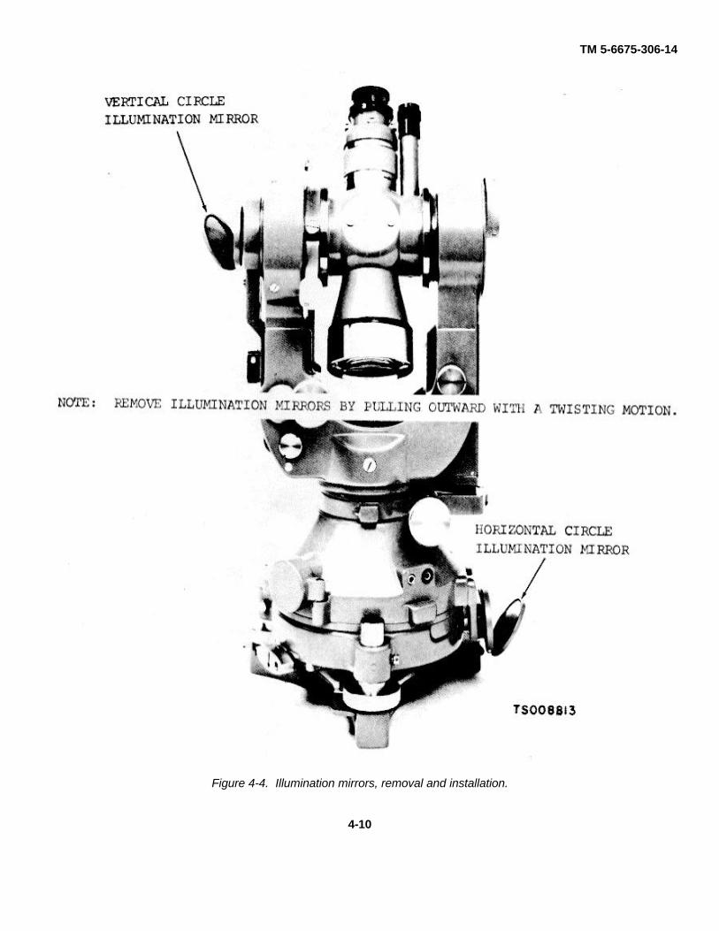
a. Removal. Refer to figure 4-4 and remove theillumination mirrors.
b. Disassembly .Refer to figure 4-5 anddisassemble the illumination mirrors.
c. Cleaning and Inspection.
WARNING
Dry cleaning solvent, P-D-680, used toclean parts is potentially dangerous topersonnel and property. Avoid repeatedand prolonged skin contact. Do not usenear open flame or excessive heat.
Flash point of solvent is 100 0 F.-138 °F. (380 C.-59 a C.)
(1) Clean the metal parts with a soft clothmoistened with an approved cleaning solvent. Cleanthe mirror with a camel's hair brush if dusty, and with thechamois if foggy.
(2) Inspect the hinge action for stiff or loosemovement. It should remain in the position whereplaced. Inspect the push-fit mirror mounting for closefit, distortion, and other damage. Oil the hinge sparinglyif needed and wipe off all excess oil. Inspect for a lost,cracked, or broken mirror.
(3) Replace a defective illumination mirror.
d. Reassembly. Refer to figure 4-5 andreassemble the illumination mirrors.
e Installation. Refer to figure 4-4 and install theillumination mirrors.
4-9
TM 5-6675-306-14
Figure 4-4. Illumination mirrors, removal and installation.
4-10

TM 5-6675-306-14
1. Mirror sleeve 2. Mirror axis 3. Pin 4. Mirror 5. Mirror mount 6. Setscrew
Figure 4-5. Illumination mirrors, disassembly and reassembly.
4-11
TM 5-6675-306-14
Section XI. TRIPODASSEMBLY, PLUMB BOB, ANDTRIPODWRENCH
4-19. GeneralThe tripod assembly is of the extension leg type whichconsists of the tripod head, tripod leg assemblies, andthe cover plate. When the theodolite is being used forsurveying work and other precision measuring, it ismounted on the tripod head. The plumb bob and tripodwrench are kept in the tripod accessory case mountedon one of the tripod legs. When installed on the tripod,the plumb bob makes it possible to center theinstrument exactly over the station point. The tripodwrench is used to tighten or loosen the clamping screwsunder the tripod head to hold the tripod legs in position.
4-20. Tripod Assembly
a. Disassembly. Refer to figure 4-6 anddisassemble the tripod assembly.
b. Cleaning and Inspection.
WARNING
Dry cleaning solvent, P-D680, used toclean parts is potentially dangerous topersonnel and property. Avoid repeatedand prolonged skin contact. Do not usenear open flame or excessive heat.Flash point of solvent is 100 ' F.-138 0F. (38 ° C.-59 a C.)
(1) Clean all parts with an approved cleaningsolvent and dry thoroughly. Clean the wooden partswith a soft cloth moistened with water and drythoroughly. Clean the strap with saddle soap.
(2) Inspect the tripod leg housings and cover forburrs, cracks, and wear. Inspect the head and cover forburrs, scratches, cracks, and breaks. Inspect the bridgefor bends, burrs, wear, and damage. Inspect theclamps, shoes, and battery box bracket for cracks,breaks, and wear.
(3) Inspect the strap for cuts, wear, and damagedseams. Inspect the wooden legs for cracks, splits, wear,and warping.
(4) Remove all burrs and scratches. Straightendents and bends. Surfaces normally painted shall bepainted in accordance with MIL- T-704, Type B. Theinstrument contact surface of the tripod head and thethreaded portion of the instrument fastener shall not bepainted.
(5) Replace all defective parts that cannot berepaired.
c. Reassembly. Refer to figure 4-6 andreassemble the tripod assembly.
4-12

TM 5-6675-306-14
Figure 4-6. Tripod, disassembly and reassembly.
4-13

TM 5-6675-306-14
KEY to fig. 4-6:1. Plastic tripod head cover 19. Wooden leg (3)2 Tripod head plate 20. Carrying strap3. Washer 21. Legholder4. Central fixing screw 22. Clamp jaw5. Clamp jaw (2) 23. Screw (3)6. Nut (3) 24. Legholder (2)7. Bearing (6) 25. Wedge (3)8. Leather strap 26. Screw (3)9. Screw 27. Bracket (6)10. Plate clamp (3) 28. Wooden dowel (3)11. Wing screw (3) 29. Wooden leg (3)12. Clamp band (2) 30. Screw (6)13. Stop plate (3) 31. Screw (3114. Screw (6) 32. Stop plate (3)15. Nut (31 33 Clamp band16. Shoe (3) 34. Screw (4)17. Washer (3) 35. Bracket (2)18. Screw (3) 36. Rivet (4)
4-21. Plumb Bob and Tripod Wrencha. Plumb Bob.
(1) Disassembly. Refer to figure 4-7 anddisassemble the plumb bob.
(2) Cleaning, inspection, and repair.
WARNINGDry cleaning solvent, P-D-680, used toclean parts is potentially dangerous topersonnel and property. Avoid repeatedand prolonged skin contact. Do not usenear open flame or excessive heat.Flash point of solvent is 100 °F. -138'F. (38 0 C.-59 0 C.)
(a) Clean all metal parts with an approved cleaningsolvent and dry thoroughly.
(b) Inspect the bayonet socket, ring, slide, andplumb bob for signs of wear, cracks, or breaks. Inspectthe lugs on the bayonet socket for burrs. Inspect thecord for wear.
(c) Remove all burrs and replace damaged ordefective parts. Use new cord when re- assembling theplumb bob.
(3) Reassembly. Refer to figure 4-7 andreassemble the plumb bob.
b. Tripod Wrench.
(1) Removal. Remove the tripod wrench fromthe tripod accessory case (fig. 2-4).
WARNINGDry cleaning solvent, P-D-680, used toclean parts is potentially dangerous topersonnel and property. Avoid repeatedand prolonged skin contact. Do not usenear open flame or excessive heat.Flash point of solvent is 100 0 F.-138°F. (38I C. -590C.)
(2) Cleaning, inspection and repair. Clean thewrench with an approved cleaning solvent and drythoroughly. Inspect the wrench for wear, burrs, cracks,or breaks. Remove minor burrs from the wrench.Check to see whether the wrench engages the bolts onthe tripod head in a satisfactory manner. Replace adamaged or defective tripod wrench. Stow the wrenchin the tripod accessory case.
4-14

TM 5-6675-306-14
Figure 4-7. Plumb bob, disassembly and reassembly.
4-15

TM 5-6675-306-14KEY to fig. 4-7:1 Ring 4. Adjuster slide2 String 5. Nut3. Bayonet socket 6. Plumb bob
Section XII. ACCESSORIES
4-22. GeneralThe accessories consist of a plastic cover to protect thetheodolite when not in use; a black sunglass whichprotects against eye damage when performingobservations against direct sunlight; two lamp fittingsused to install the illumination system; two adjusting pinsand a screwdriver used to adjust the horizontal axis,vertical reading assembly, and vertical collimation level::? brush and chamois used to clean the theodolite; agrease container used to store approved lubricant; anddiagonal microscope and telescope eyepieces used forhigh angle observations. When not in use allaccessories are stored in the accessory case.4-23. Adjusting Pins and Screwdrivera. Removal. Remove the adjusting pins andscrewdriver from the accessory case (fig. 2-5i.b. Cleaning, inspection and repair.
WARNINGDry cleaning solvent, P-D-680, used toclean parts is potentially dangerous topersonnel and property. Avoid repeatedand prolonged skin contact. Do not usenear open flame or excessive heat.Flash point of solvent is 100° F.-138 F.(380 C.-590 C.)
(1) Clean adjusting pins and screwdriver with anapproved solvent and dry thoroughly.(2) Inspect adjusting pins and screwdriver forbends, nicks, scratches, burrs, and damage.(3) Remove all burrs and scratches; straightendents and bends.(4) Replace defective adjusting pin or screwdriver.c. Installation. Install adjusting pins andscrewdriver in accessory case (fig. 2-5).
4-24. Black Sunglassa. General. The black sunglass is push-fit on thetelescope eyepiece (fig. 2-5).b. Cleaning and Inspection.
WARNINGDry cleaning solvent, P-D-680, used toclean parts is potentially dangerous topersonnel and property. Avoid repeatedand prolonged skin contact. Do not usenear open flame or excessive heat.Flash point of solvent is 100 ° F.-138 °F. (380 C.- 59 ° C.)
(1) Clean the metal part of the black sunglass usingclean cloth dampened with an approved cleaningsolvent.(2) Clean the lens with a soft brush, lens tissue oran approved cleaning solvent.(3) Inspect the eyepiece for bent or cracked metalparts.(4) Replace a defective black sunglass.
4-25. Diagonal Telescope and DiagonalMicroscope Eyepieces
a Removal. Refer to figure 2-13 and removethe diagonal eyepieces.
b. Cleaning and Inspection.WARNING
Dry cleaning solvent, P-D-680, used toclean parts is potentially dangerous topersonnel and property. Avoid repeatedand prolonged skin contact. Do not usenear open flame or excessive heat.Flash point of solvent is 1000 F.-138 °F. (380 C.-59 0 C.)
(1) Clean all parts except the lenses with a cleancloth dampened with an approved cleaning solvent.
(2) Clean the lenses with a soft brush, lens tissue,or an approved cleaning solvent.
(3) Inspect the lenses for chips, cracks and fungusetching.Inspect the metal parts for bends, breaks, andworn or damaged threads.
(4) Replace defective diagonal eyepieces.c. Installation. Refer to figure 2-13 and install the
diagonal eyepieces.
4-26. Dust Brush, Chamois, and Plastic Covera. General. The dust brush and chamois are used
to clean the theodolite. The plastic cover is used toprotect the theodolite.
b. Cleaning and Inspection.WARNING
Dry cleaning solvent, P-D680, used toclean parts is potentially dangerous topersonnel and property. Avoid repeatedand prolonged skin contact. Do not usenear open flame or excessive heat.Flash point of solvent is 1000 F.-138'F. (380C.-590C.)
(1) Clean the dust brush with an approved solvent.
Change 2 4-16

TM 5-6675-306-14
(2) Clean plastic cover with a clean cloth dampenedwith an approved solvent.
(3) Inspect dust brush for loose, frayed, or brokenbristles.
(4) Inspect plastic cover for cracks and rips.
(5) Inspect chamois for rips and frays.
(6) Replace defective dust brush, plastic cover orchamois.
4-27. Grease Containera. General. The grease container is used to store
approved lubricant.
b. Cleaning and Inspection.
WARNING
Dry cleaning solvent, P-D-680, used toclean parts is potentially dangerous topersonnel and property. Avoid repeatedand prolonged skin contact. Do not usenear open flame or excessive heat.Flash point of solvent is 100° F-138°F.(38°C.-59°C.)
(1) Clean grease container with a clean clothdampened with an approved solvent.
(2) Inspect grease container for cracks, chips, andwear.
(3) Replace defective grease container.
4.28. Lamp Fittingsa. Removal. Refer to figure 3-2 and remove the
lamp fittings.
b. Cleaning and Inspection.
WARNINGDry cleaning solvent, P-D680, used toclean parts is potentially dangerous topersonnel and property. Avoid repeatedand prolonged skin contact. Do not usenear open flame or excessive heat.Flash point of solvent is 100° F.-138°F. (38 ° C.-59 ° C.)
(1) Clean lamp fittings with cloth dampened with anapproved solvent.
(2) Inspect lamp fittings for worn or damagedthreads, bent or broken metal parts, chips orcracks.
(3) Replace defective lamp fittings.
c. Installation. Refer to figure 3-2 and install thelamp fittings.
4-29. Accessory Casea. General. The accessory case is used to stow all
accessories when not in use (fig. 2-5).
b. Cleaning and Inspection.
(1) Brush the accessory case free of dust and dirt.
(2) Inspect the accessory case for rips, torn straps,and damage defects that would render itunserviceable.
(3) Replace defective accessory case.
4-17

TM 5-6675-306-14
CHAPTER 5
DIRECT SUPPORT AND GENERAL SUPPORT
Section I. MAINTENANCE INSTRUCTIONS
5-1. Tools and EquipmentTools, equipment, and repair parts issued with troopinstalled, or authorized for the theodolite are listed in thebasic issue items list and items troop installed orauthorized list, Appendix B.5-2. Special Tools and EquipmentThe special tools required to perform direct support and
general support maintenance on the theodolite are listedin table 5-1. References and illustrations indicating theuse of these tools are listed in the table. No specialequipment is required by organizational maintenancepersonnel for performing maintenance on the theodolite.
Table 5-1. Special Tools
Item NSN or Reference No Reference Use Fig * *Figure Paragraph
Pin, adjusting (89905)* 6675-00-353-4103 2-5 2-9 Adjusting theodolite adjustingscrews.
Wrench, tripod (89905)* 5120-00-378-9520 2-4 2.2 Tripod leg adjustment,removal, and installation.
Wrench, Tripod (89905)* None 6-2 To remove and install base 5-1plate nut and lock nut.
* Federal supply code for manufacturer* * Fabrication drawings in this manual
5-3. Maintenance Repair PartsRepair parts and equipment are listed and illustrated inthe repair parts and special tools list, TM 5-6675-306-
24P, covering direct support and general supportmaintenance of this equipment.
5-1
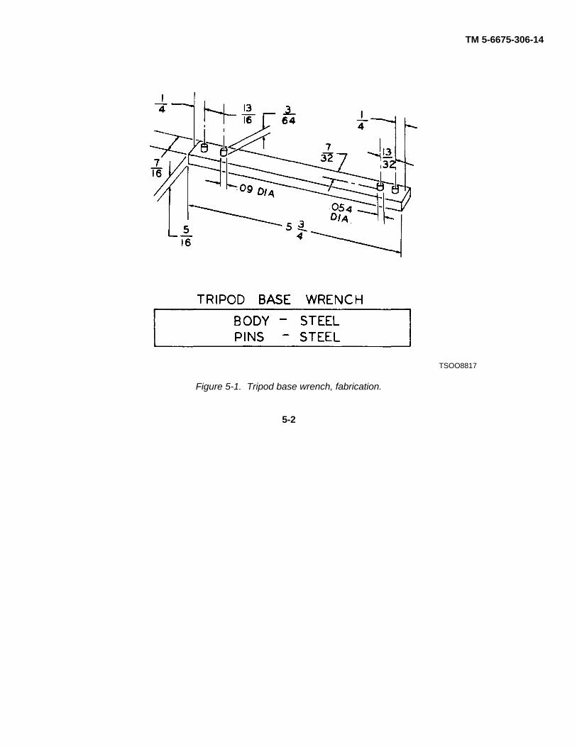
TM 5-6675-306-14
TSOO8817
Figure 5-1. Tripod base wrench, fabrication.
5-2
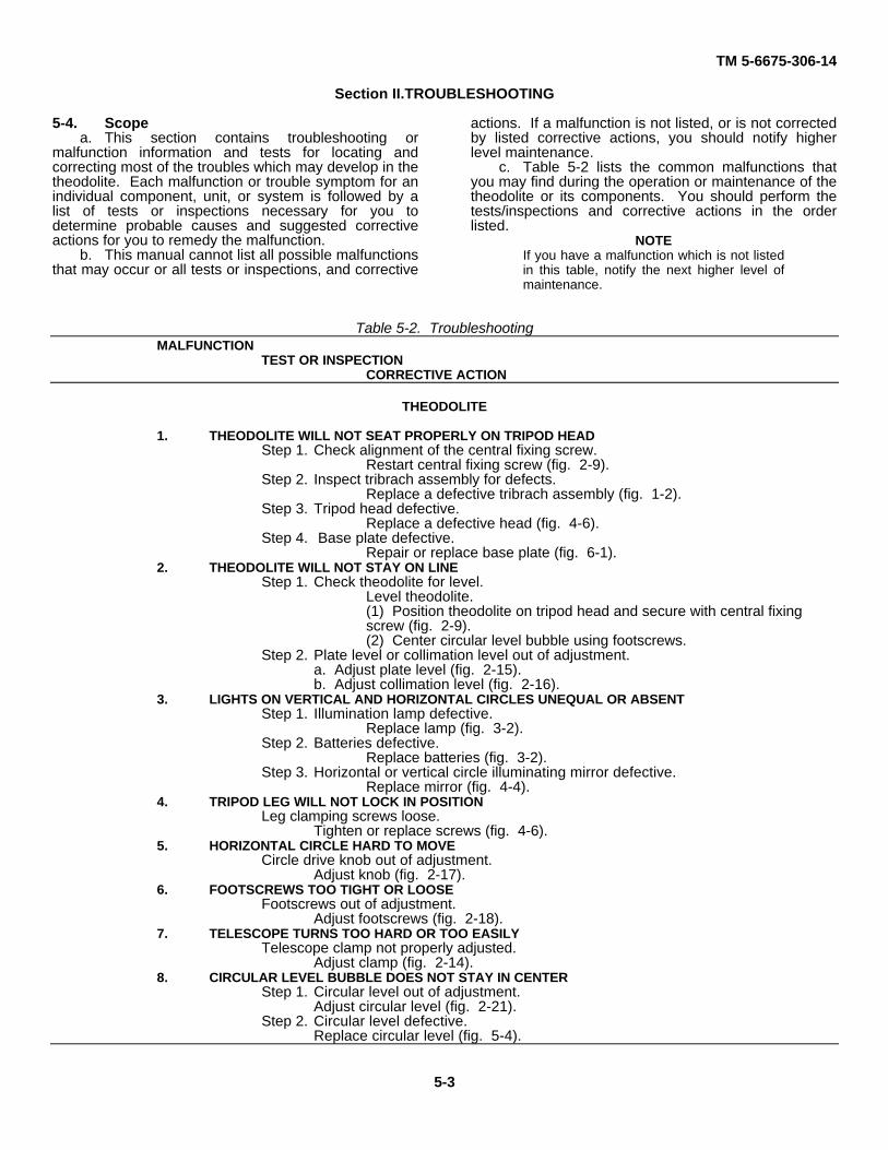
TM 5-6675-306-14
Section II.TROUBLESHOOTING
5-4. Scopea. This section contains troubleshooting or
malfunction information and tests for locating andcorrecting most of the troubles which may develop in thetheodolite. Each malfunction or trouble symptom for anindividual component, unit, or system is followed by alist of tests or inspections necessary for you todetermine probable causes and suggested correctiveactions for you to remedy the malfunction.
b. This manual cannot list all possible malfunctionsthat may occur or all tests or inspections, and corrective
actions. If a malfunction is not listed, or is not correctedby listed corrective actions, you should notify higherlevel maintenance.
c. Table 5-2 lists the common malfunctions thatyou may find during the operation or maintenance of thetheodolite or its components. You should perform thetests/inspections and corrective actions in the orderlisted.
NOTEIf you have a malfunction which is not listedin this table, notify the next higher level ofmaintenance.
Table 5-2. TroubleshootingMALFUNCTION
TEST OR INSPECTIONCORRECTIVE ACTION
THEODOLITE
1. THEODOLITE WILL NOT SEAT PROPERLY ON TRIPOD HEADStep 1. Check alignment of the central fixing screw.
Restart central fixing screw (fig. 2-9).Step 2. Inspect tribrach assembly for defects.
Replace a defective tribrach assembly (fig. 1-2).Step 3. Tripod head defective.
Replace a defective head (fig. 4-6).Step 4. Base plate defective.
Repair or replace base plate (fig. 6-1).2. THEODOLITE WILL NOT STAY ON LINE
Step 1. Check theodolite for level.Level theodolite.(1) Position theodolite on tripod head and secure with central fixingscrew (fig. 2-9).(2) Center circular level bubble using footscrews.
Step 2. Plate level or collimation level out of adjustment.a. Adjust plate level (fig. 2-15).b. Adjust collimation level (fig. 2-16).
3. LIGHTS ON VERTICAL AND HORIZONTAL CIRCLES UNEQUAL OR ABSENTStep 1. Illumination lamp defective.
Replace lamp (fig. 3-2).Step 2. Batteries defective.
Replace batteries (fig. 3-2).Step 3. Horizontal or vertical circle illuminating mirror defective.
Replace mirror (fig. 4-4).4. TRIPOD LEG WILL NOT LOCK IN POSITION
Leg clamping screws loose.Tighten or replace screws (fig. 4-6).
5. HORIZONTAL CIRCLE HARD TO MOVECircle drive knob out of adjustment.
Adjust knob (fig. 2-17).6. FOOTSCREWS TOO TIGHT OR LOOSE
Footscrews out of adjustment.Adjust footscrews (fig. 2-18).
7. TELESCOPE TURNS TOO HARD OR TOO EASILYTelescope clamp not properly adjusted.
Adjust clamp (fig. 2-14).8. CIRCULAR LEVEL BUBBLE DOES NOT STAY IN CENTER
Step 1. Circular level out of adjustment.Adjust circular level (fig. 2-21).
Step 2. Circular level defective.Replace circular level (fig. 5-4).
5-3

TM 5-6675-306-14
Section III. REMOVAL AND INSTALLATION OF MAJOR COMPONENTS AND AUXILIARIES
5-5. Tribrach Assemblya. Removal. Refer to figure 4-3 and remove the
tribrach assembly.
b. Installation. Refer to figure 4-3 and install thetribrach assembly.
5-6. Base Plate and Footscrewsa. Removal. Refer to figure 5-2 and remove the
base plate with the three footscrews attached from thebase casting.
b. Installation. Refer to figure 5-2 and install thebase plate and footscrew.
5-4

TM 5-6675-306-14
Figure 5-2. Base plate and footscrews, removal and installation.
5-5

TM 5-6675-306-14
5-7. Footscrew Assembly
a. Removal.
(1) Refer to figure 5-2 and remove the base plate.
(2) Refer to figure 5-3 and remove the threefootscrew assemblies.
b. Installation.
(1) Refer to figure 5-3 and install the threefootscrew assemblies.
(2) Refer to figure 5-2 and install the base plate.
5-6
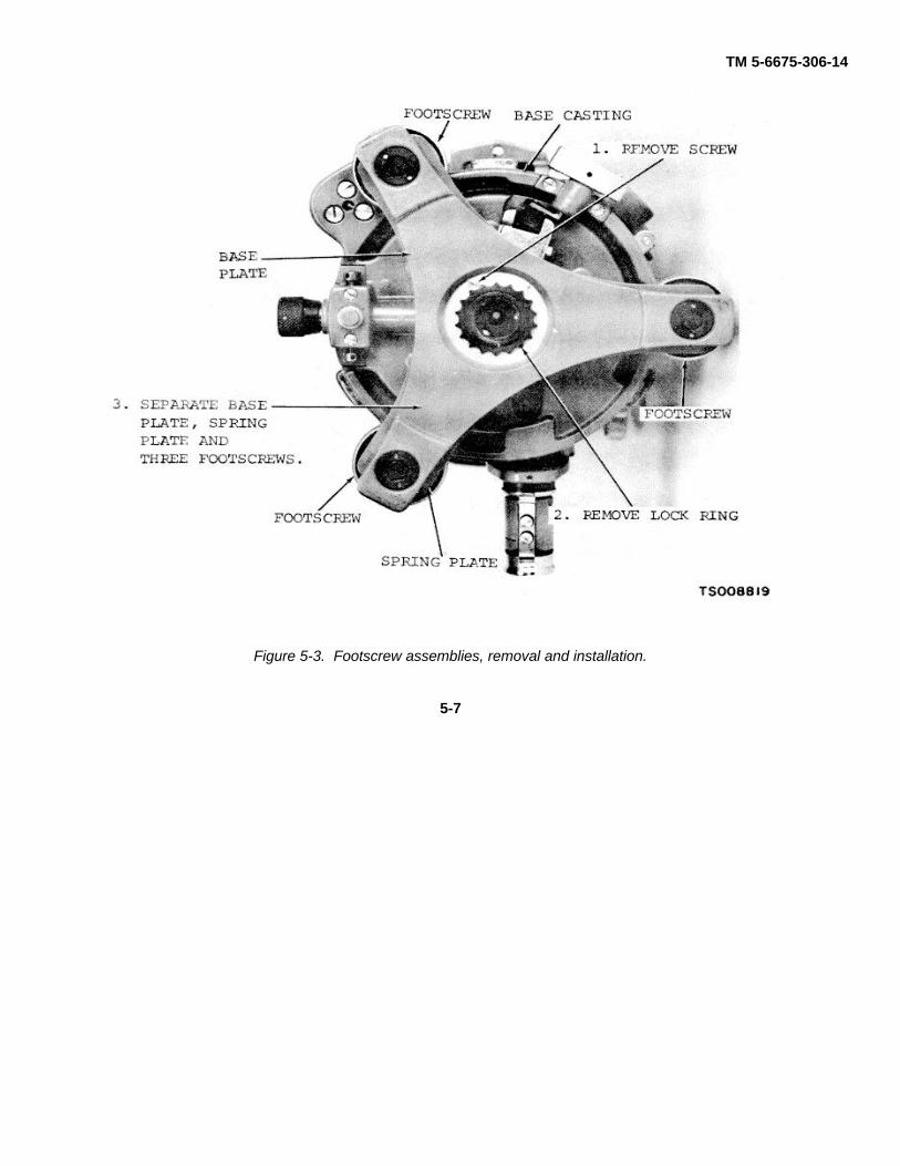
TM 5-6675-306-14
Figure 5-3. Footscrew assemblies, removal and installation.
5-7

TM 5-6675-306-14
5-8. Locking Plate, Lock Knob and Circular Levela. Removal.
(1) Refer to figure 5-2 and remove the base plateand footscrews.
(2) Refer to figure 5-4 and remove the lockingplate, lock knob and circular level.
b Installation.
(1) Refer to figure 5-4 and install the locking plate,lock knob and circular level.
(2) Refer to figure 5-2 and install the base plate andfootscrews.
KEY to figure 5-4:1. Circular level vial 10. Nut2. Spring washer 11. Machine screw3. Machine screw (3) 12. Pin4. Lock plate 13. Lock knob5. Stop 14. Bearing6. Machine screw 15. Machine screw7. Clamp chuck 16. Spring8. Locking lever 17. Machine screw9. Lock knob assembly
mounting screw (2)
5-8

TM 5-6675-306-14
Figure 5-4. Locking plate, lock knob and circular level, removal disassembly and installation.
5-9

TM 5-6675-306-14
5-9. Accessoriesa. Removal. Remove all accessories from
accessory case (fig. 2-5).
b. Installation. Store all accessories in accessorycase (fig. 2-5).
5-10. Black Sunglassa. Removal. Remove black sunglass from
accessory case (fig. 2-5). If installed, carefully pullblack sunglass from telescope eyepiece or telescopediagonal eyepiece.
b. Installation. Store black sunglass in accessorycase; install by pushing black sunglass over telescopeeyepiece or telescope diagonal eyepiece.
5-11. Lamp Fittingsa. Removal. Refer to figure 3-2 and remove the
lamp fittings.
b. Installation. Refer to figure 3-2 and install thelamp fittings.
5-12. Diagonal Telescope and DiagonalMicroscope Eyepieces
a. Removal. Refer to figure 2-13 and remove thediagonal eyepieces.
b. Installation. Refer to figure 2-13 and install thediagonal eyepieces.
5-13. Illumination Mirrorsa. Removal. Refer to figure 4-4 and remove the
illumination mirrors.
b. Installation. Refer to figure 4-4 and install theillumination mirrors.
5-14. Sunshadea. Removal. Carefully pull the sunshade from the
telescope objective (fig. 2-13). If in stored position,twist sunshade so that slot in sunshade is aligned withfront sight; then pull sunshade from telescope objective.
b. Gently push sunshade over telescope objectiveso that edge of sunshade is against front sight (fig. 2-13). To store, align slot in sunshade with front sight;then push sunshade over telescope objective and twistslightly to lock in place.
5-15. Handlamp and Connecting Cablea. Removal. Remove handlamp and connecting
cable from battery box.b. Installation. Store handlamp and connecting
cable in battery box.
5-10

TM 5-6675-306-14CHAPTER 6
REPAIR OF TRIBRACH ASSEMBLY
Section I. GENERAL
6-1. DescriptionThe tribrach assembly consists of the base plate, lockingplate, footscrews, circular level, optical plummet, andlock knob. The tribrach assembly forms a leveling basebetween the theodolite and the tripod head. The baseplate provides a means
for securing the theodolite to the tripod, with theutilization of the tripod central fixing screw. Leveling isaccomplished by means of the foot- screws. Preciselocation of the theodolite over the station point isverified by sighting through the optical plummet.
Section II. TRIBACH ASSEMBLY COMPONENTS
6-2. Base Plate
a. General. The base plate is used to secure thetheodolite to the tripod by means of the tripod centralfixing screw.
b. Removal.
(1) Refer to figure 4-3 and remove the tribrachassembly.
(2) Refer to figure 5-2 and remove the base plate.
c. Disassembly. Refer to figure 6-1 anddisassemble the base plate.
6-1

TM 5-6675-306-14
Figure 6-1. Base plate, disassembly and reassembly.
6-2

TM 5-6675-306-14
NOTETripod base wrench (fig. 5-1) required to remove and installcenter nut (2) and lock nut (6).
KEY to fig. 6-1:1 Setscrew 6. Screw2. Center nut 7. Lock ring3. Spring plate 8. Lock nut4 Lock nut 9. Pad5. Base plate
d. Cleaning, inspection, and repair.
WARNINGDry cleaning solvent, P-D-680, used toclean parts is potentially dangerous topersonnel and property. Avoid repeatedand prolonged skin contact. Do not usenear open flame or excessive heat.Flash point of solvent is 1000 F.-138 0F. (38 0 C.-59 ° C.)
(1) Clean all parts with an approved cleaningsolvent and dry thoroughly.
(2) Inspect the base plate and the spring plate fordents, cracks, breaks, and burrs. Inspect all threadedparts and hardware for worn or damaged threads.
(3) Remove all burrs and dents.
(4) Replace all defective parts that cannot berepaired.
e. Reassembly. Refer to figure 6-1 andreassemble the base plate.
f. Installation.
(1) Refer to figure 5-2 and install the base plate.
(2) Refer to figure 4-3 and install the tribrachassembly.
6-3. Footscrews
a General Three footscrews are used to level thetheodolite.
b. Removal.
(1) Refer to figure 4-3 and remove the tribrachassembly.
(2) Refer to figure 5-2 and remove the base plate.
(3) Refer to figure 5-3 and remove the footscrews.
c. Disassembly. Refer to figure 6-2 anddisassemble the footscrews.
6-3
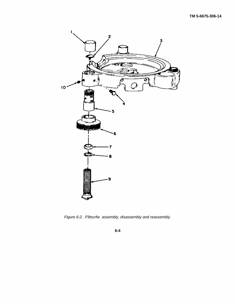
TM 5-6675-306-14
Figure 6-2. F9tscrfw assembly, disassembly and reassembly.
6-4

TM 5-6675-306-14
CAUTIONStop screw (2) has a left-hand thread.
KEY to fig. 6-21. Dust cover (3) 6. Milled knob (3)2. Stop screw 13) 7. Washer (3)3 Base casting 11) 8. Washer (3)4. Adjusting screw (3) 9. Machine screw 1315. Adjustable nut (3) 10. Setscrew 13)d. Cleaning, inspection and repair.
WARNINGDry cleaning solvent, P-D-680, used toclean parts is potentially dangerous topersonnel and property. Avoid repeatedand prolonged skin contact. Do not usenear open flame or excessive heat.Flash point of solvent is 100 ° F.-138 °F. (38 0 C.-59 0 C.)
(1) Clean all parts with an approved cleaningsolvent and dry thoroughly.
(2) Inspect the spindles for bends. Inspect allthreaded parts for worn or damaged threads.
(3) Replace all defective parts that cannot berepaired.
e Reassembly. Refer to figure 6-2 andreassemble the footscrews.
f Installation.
(1) Refer to figure 5-3 and install the footscrews.(2) Refer to figure 5-2 and install the base plate.(3) Refer to figure 4-3 and install the tribrach
assembly.
6-4. Locking Plate, Lock Knob and Circular Level
a. General. The locking plate is used to secure thetheodolite to the tribrach assembly. The lock knob isused to release the theodolite from thetribrach. The circular level is used to level thetheodolite.
b. Removal.
(1) Refer to figure 5-2 and remove the base plateand footscrews.
(2) Refer to figure 5-4 and remove the lockingplate, lock knob, and circular level (para 5-8).
c. Disassembly. Refer to figure 5-4 anddisassemble the lock knob and locking plate.
d. Cleaning, inspection and repair.
WARNINGDry cleaning solvent, P-D-680, used toclean parts is potentially dangerous topersonnel and property. Avoid repeatedand prolonged skin contact. Do not usenear open flame or excessive heat.Flash point of solvent* is 100 0 F.-138 °F. (38°C.-59°C.-59°C.)
(1) Clean all metal parts with an approved cleaningsolvent and dry thoroughly. Wipe the level vial with lenstissue or a lens cloth.
(2) Inspect the level vial for cracks, scratches, andbroken vial tip. Inspect the locking plate, stop plate andlever for bends, burrs, and cracks. Inspect the springsfor cracks. Inspect all threaded parts for worn ordefective threads.
(3) Remove all burrs and straighten bends.
(4) Replace all defective parts that cannot berepaired.
e Reassembly. Refer to figure 5-4 andreassemble the locking plate and lock knob.
f. Installation.
(1) Refer to figure 5-4 and install the circular level,locking plate, and lock knob.
(2) Refer to figure 5-2 and install the base plate.
6-5

TM 5-6675-306-14
CHAPTER 7
REPAIR OF BATTERY BOX, HANDLAMP AND CONNECTING CALBE,AND LAMP FITTINGS
Section I. GENERAL
7-1. DescriptionThe illumination system consists of two lamp fittings anda battery box, with a rheostat to control the intensity oflight illuminating the horizontal, vertical, and micrometer
circles. A handlamp with a connecting cable that plugsinto the battery box is also provided for general externallighting purposes.
Section II. BATTERY BOX, HANDLAMP AND CONNECTING CALBE-AND LAMP FITTINGS
7-2. Battery Boxa. General. The battery box stores the batteries
which provide power for the illumination system. Arheostat on the battery box controls illuminationbrightness.
b. Disassembly. Refer to figure 7-1 anddisassemble the battery box.
c. Cleaning, inspection, and repair.
WARNINGDry cleaning solvent, P-D-680, used toclean parts is potentially dangerous topersonnel and property. Avoid repeatedand prolonged skin contact. Do not usenear open flame or excessive heat.Flash point of solvent is 100 ° F.- 138 °F.(38 ° C.-59 ° C.)
(1) Clean all metal parts with an approved cleaningsolvent and dry thoroughly. Wipe all corrosion fromterminals and contacts. Wipe dirt and other foreign
matter from cables, lamp trunk, springs, washers, andrheostat.
(2) Inspect the cables and contacts forcracked, swollen, or damaged insulation, broken wires,and defective terminals. Inspect the springs for bends,breaks, and fatigue.
(3) Inspect the lamp trunk for cracks and otherdamage. Inspect the rheostat for improper operation andother damage. Inspect the sockets for cracks and wear.Inspect the springs for bends, breaks, and fatigue.Inspect the contacts and slide lever for wear, burrs, andbends.
(4) Inspect the battery box for dents, cracks, anddefective mounting bracket, clamps, and carrying strap.
(5) Remove all burrs and straighten dents. Replaceall defective parts that cannot be repaired.
d Reassembly. Refer to figure 7-1 andreassemble the battery box.
7-1

TM 5-6675-306-14
Figure 7-1. Battery box, disassembly and reassembly.
7-2
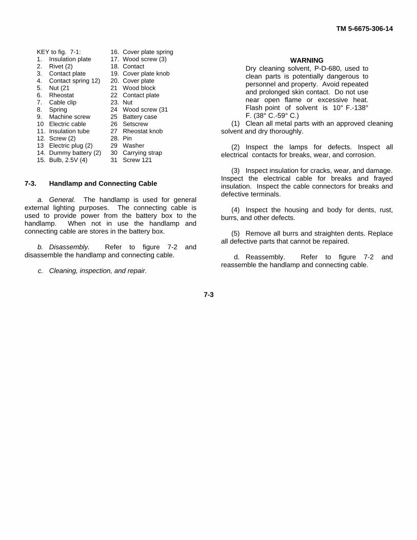
TM 5-6675-306-14
KEY to fig. 7-1: 16. Cover plate spring1. Insulation plate 17. Wood screw (3)2. Rivet (2) 18. Contact3. Contact plate 19. Cover plate knob4. Contact spring 12) 20. Cover plate5. Nut (21 21 Wood block6. Rheostat 22 Contact plate7. Cable clip 23. Nut8. Spring 24 Wood screw (319. Machine screw 25 Battery case10 Electric cable 26 Setscrew11. Insulation tube 27 Rheostat knob12. Screw (2) 28. Pin13 Electric plug (2) 29 Washer14. Dummy battery (2) 30 Carrying strap15. Bulb, 2.5V (4) 31 Screw 121
7-3. Handlamp and Connecting Cable
a. General. The handlamp is used for generalexternal lighting purposes. The connecting cable isused to provide power from the battery box to thehandlamp. When not in use the handlamp andconnecting cable are stores in the battery box.
b. Disassembly. Refer to figure 7-2 anddisassemble the handlamp and connecting cable.
c. Cleaning, inspection, and repair.
WARNINGDry cleaning solvent, P-D-680, used toclean parts is potentially dangerous topersonnel and property. Avoid repeatedand prolonged skin contact. Do not usenear open flame or excessive heat.Flash point of solvent is 10° F.-138°F. (38° C.-59° C.)
(1) Clean all metal parts with an approved cleaningsolvent and dry thoroughly.
(2) Inspect the lamps for defects. Inspect allelectrical contacts for breaks, wear, and corrosion.
(3) Inspect insulation for cracks, wear, and damage.Inspect the electrical cable for breaks and frayedinsulation. Inspect the cable connectors for breaks anddefective terminals.
(4) Inspect the housing and body for dents, rust,burrs, and other defects.
(5) Remove all burrs and straighten dents. Replaceall defective parts that cannot be repaired.
d. Reassembly. Refer to figure 7-2 andreassemble the handlamp and connecting cable.
7-3

TM 5-6675-306-14
Figure 7-2. Handlamp and connecting cable, disassembly and reassembly.
7-4

TM 5-6675-306-14
KEY to fig. 7-2:1. Sleeve 13. Wedge2. Bulb, 2.5V 14. Copper wire3. Lamp housing 15. Hook4. Switch slide 16. Lampholder5. Screw 17. Slide switch6. Insulation 18. Plate7. Screw (21 19. Electric cable8. Contact spring 20. Electric plug9. Screw 21. Electric plug10. Rubber sleeve 22. Electric cable11. End cover 23. Insulating tube (4)12. Cable sleeve (4)
7-4. Lamp Fittingsa. General. The lamp fittings supply light for thevertical, horizontal, and micrometer circles. When not inuse, the lamp fittings are stowed in the accessory case.
b. Disassembly. Refer to figure 7-3 anddisassemble the lamp fittings.
7-5

TM 5-6675-306-14
Figure 7-3. Lamp fittings, disassembly and reassembly.
7-6

TM 5-6675-306-14
KEY to fig. 7-3:1. Screw (4) 6. Bulb2. Insulation bushing (4) 7. Lamp socket3. Contact spring (2) 8. Housing4. Insulation plate (2) 9. Cover plate5. Lamp housing 10. Groundglass
c Cleaning, inspection, and repair.
WARNINGDry cleaning solvent, P-D680, used toclean parts is potentially dangerous topersonnel and property. Avoid repeatedand prolonged skin contact. Do not usenear open flame or excessive heat.Flash point of solvent is 100° F-138°F.(38°C.-59°C.)
(1) Clean all metal parts with an approvedcleaning solvent and dry thoroughly. Clean thegroundglass with lens tissue or a lens cloth.
(2) Inspect the groundglass for cracks, chips,scratches, and etching. Inspect the lamp for defects.Inspect the contact springs for bends, wear, and fatigue.Inspect the insulators for wear and damage.
(3) Replace all defective parts that cannot berepaired.
d Reassembly. Refer to figure 7-3 andreassemble the lamp fittings.
7-7

TM 5-6675-306-14
APPENDIX A
REFERENCES
A-1. LubricationC91OOIL Fuels, Lubricants, Oils, and Waxes
A-2. PaintingTM 9-213 Painting Instructions for Field Use
A-3. MaintenanceFM 29-2 Organizational Maintenance ManagementTB 750-97-66 Maintenance Expenditure Limits for FSC Group 66TM 38-750 The Army Maintenance Management SystemTM 5-6675-306-24P Organizational, Direct Support and General Support Maintenance
Repair Parts and Special Tools List (Including Depot Maintenance Repair Parts and Special Tools) 'Theodolite, Survey, Directional 1 Second Graduation; Wild Heerbrugg Model T2-74 Deg.
A-4. Shipment and StorageTM 740-90-1 Administrative Storage of Equipment
A-5. DemolitionTM 750-244-3 Destruction of Equipment to Prevent Enemy Use
A-1

TM 5-6675-306-14
APPENDIX BCOMPONENTS OF END ITEMS LIST
B-1. Scope.
This appendix lists Integral Components of and BasicIssue Items (BII) for the directional thedolite to help youinventory items required for safe and efficient operation.
B-2. General.
The components of end item list are divided into thefollowing sections:
a. Section II. Integral Components of the EndItem. These items, when assembled, comprise thedirectional theodolite and must accompany it when- everit is transferred or turned in. These illustrations will helpyou identify these items.
b Section II. Basic Issue Items. These areminimum essential items required to place thedirectional theodolite in operation, to operate it and toperform emergency repairs. Although shippedseparately packed, they must accompany the directionaltheodolite during operation and whenever it istransferred between accountable officers. Theillustrations will assist you with hard-to-identify items.This manual is your authority to requisition replacementBII based on Table(s) of Organization and Equipment(TOE/Modification Table of Organization and Equipment(MTOE) authorization of the end item.
B-3. Explanation of Columns.
a. Illustration. This column is divided as follows:
(1) Figure Number. Indicates the figure number ofthe illustration on which the item is shown (if applicable).
(2) Item Number. The number used toidentify item called out in the illustration.
b. National Stock Number (NSN). Indicates thenational stock number assigned to the end item whichwill be used for requisitioning.
c. Part Number (P/N). Indicates the primarynumber used by the manufacturer which controls thedesign and characteristics of the item by means of itsengineering drawings, specifications, standards andinspection requirements to identify an item or range ofitems.
d. Description. Indicates the federal item nameand, if required, a minimum description to identify theitem.
e. Location. The physical location of each itemlisted is given in this column. The lists are designed toinventory all items in one area of the major item beforemoving on the adjacent area.
f. Usable on Code. "USABLE ON" codes areincluded to help you identify which component items areused on the different models. Identification of the codesused in this list are:
CODE NOT APPLICABLE
g. Quantity Required (Qty Reqd). This columnlists the quantity of each item required for a completemajor item.
h. Quantity. This column is left blank for useduring inventory. Under the received column, list thequantity you actually receive on your major item. Thedate columns are for use when you inventory the majoritem at a later date, such as for shipment to another site.
Change 1 B-1

TM 5-6675-306-14Section II INTEGRAL COMPONENTS OF END ITEM
(1) (2) (3) (4) (5) (6) (7) (8)ILLUSTRATION QUANTITY
(A) (B) NATIONAL PART NO. USABLEFIGURE ITEM STOCK & ON QTY RCVD DATE DATE DATE
NO. NO. NUMBER FSCM DESCRIPTION LOCATION CODE REQD
4-3 6675-00-065- 314519 Tribrach 18527 (89905) Assembly
2-13 6675-00-979- 311850 Sunshade 18744 (89905)
2-14 6675-00-014- 360473 Illumin- 23516 (89905) ation Mirror
Assembly2-1 Case Assy
Carryingconsistingof:
2-1 6675-00-037- 316055 Hood Assy 10253 (89905)
2-1 6675-00-963- 158656-74 Base Assy 16365 (89905)
2-2 6675-00-127- 316083 Desiccant 12857 (89905) Container
2-1 06675-00-036- 316110 Case 15616 (89905) Shipping
2-5 Case Acces-sory contain-ing thefollowing:
2-5 1 6675-00-980- 134253 Case Acces- 10118 (89905) sory
2-5 2 6675-00-014- 311846 Cover, 13518 (89905) Instrument
2-5 3 6675-00-378- 284836 Sunglass, 19401 (89905) black
2-5 9 6675-00-014- 316106 Lamp 23519 (89905) Fittings
2-5 10 6675-00-378- 323133 Eyepiece, 19497 (89905) Telescope
diagonal2-5 11 6675-00-378- 323134 Eyepiece, 1
9498 (89905) Micro-scopediagonal
2-6 Not BatteryApplicable Box Assy
contain-ing thefollowing:
2-6 6675-00-997- 310443 Box Assy 14340 (89905)
2-6 6135-00-937- 310432 Battery, 24118 (89905) Dummy
2-6 6675-00-997- 246416 Cable, 14341 (89905) Connecting
2-6 6675-00-714- 268034 Light, 11375 (89905) Hand
2-7 6675-00-023- 202573 Haversack 15052 (89905)
2-8 Tripod 1AssyExtensionLeg, consist-
i ing of:2-8 6675-00-641- GST20-1 Tripod 1
3572 (89905) Assy2-8 6675-00-378- 319062 Cover, 1
9525 (89905) Tripod2-8 6675-00-036- 319164 Tripod 12-8 (89905) Accessory
Case2-4 2 5120-00-011- 166494 Wrench, 1
8393 (89905) Tripod2-4 3 5210-00-869- 319010 Plumb 1
3744 (89905) Bob Assyw/adjuster
Change 1 B-2

TM 5-6675-306-14
Section II INTEGRAL COMPONENTS OF END ITEM
(1) (2) (3) (4) (5) (6) (7) (8)ILLUSTRATION QUANTITY
(A) (B) NATIONAL PART NO. USABLEFIGURE ITEM STOCK & ON QTY RCVD DATE DATE DATE
NO. NO. NUMBER FSCM DESCRIPTION LOCATION CODE REQD
TM 5-6675-00-306-14Operator,Organization-al DirectSupport,GeneralSupportMaintenanceManual
2-5 6 7920-00-378- 109335 Brush, 19524 (89905) Dust
2-5 8 8330-00-965- 166684 Chamois 11722 (89905)
2-5 7 6675-00-446- 167226 Container, 11762 (89905) Lubricant
2-6 6675-00-859- 166370 Lamps 45936 (89905)
2-5 4 6675-00-353- 109334 Pin, 24103 (89905) Adjusting
2-5 5 5120-00-446- 166786 Screw- 12860 (89905) driver,
Jewelers
Change 1 B-3/(B-4 blank)

TM 5-6675-306-14
APPENDIX CADDITIONAL AUTHORIZATION LIST
Section I. INTRODUCTION
C-1. Scope.
This appendix lists additional items you are authorizedfor the support of directional theodolite.
C-2. General.
This list identifies items that do not have to accompanythe directional theodolite and that do not have to be
turned in with it. These items are authorized to you byCTA, MTOE, TDA or JTA.
C-3. Explanation of Listing.
National stock number, descriptions and quantities areprovided to help you identify and request the additionalitems you require to support this equipment.
Section II. ADDITIONAL AUTHORIZATION LIST
(1) (2) (3) (4)NATIONAL PART NUMBER USABLE
STOCK & ON QTYNUMBER FSCM DESCRIPTION CODE U/M AUTH
6135-00-120-1020 BA30 (81349) Battery, Dry, 1.5 Volts EA 8
Change 1 C-1/(C-2 blank)
TM 5-6675-306-14
APPENDIX D
MAINTENANCE ALLOCATION CHART
D-1. Generala. This section provides a general explanation of
all maintenance and repair functions authorized atvarious maintenance levels.
b. Section II designates overall responsibility forthe performance of maintenance functions on theidentified end item or component and the workmeasurement time required to perform the functions bythe designated maintenance level. The implementationof the maintenance functions upon the end item orcomponent will be consistent with the assignedmaintenance functions.
c. Section III lists the tools and test equipmentrequired for each maintenance function as referencedfrom Section II.
D-2. Explanation of Columns in Section IIa. Column 1), Group Number. Column 1 list group
numbers to identify related components, assemblies,sub-assemblies, and modules and their next higherassembly. The applicable groups are listed in the MACin disassembly sequence beginning with the first groupremoved.
b. Column (2), Component/Assembly. Thiscolumn contains the noun names of components,assemblies, sub-assemblies and modules for whichmaintenance is authorized.
c. Column (3), Maintenance Functions. Thiscolumn lists the functions to be performed on the itemlisted in Column 2. The maintenance functions aredefined as follows:
(1) Inspect.To determine serviceability of an itemby comparing its physical, mechanical, or electricalcharacteristics with established standards throughexamination.
(2) Test. To verify serviceability and detectincipient failure by measuring the mechanical orelectrical characteristics of an item and comparing thosecharacteristics with prescribed standards.
(3) Service. Operations required periodicallyto keep an item in proper operating condition, i.e., toclean (decontaminate), to preserve to drain, to paint, orto replenish fuel, lubricants, hydraulic fluids, orcompressed air supplies.
(4) Adjust. To maintain within prescribed limits, bybringing into proper or exact position, or by setting theoperating characteristics to specified parameters.
(5) Align. To adjust specified variable elements ofan item to bring about optimum desired performance.
(6) Calibrate. To determine and cause correctionsto be made or to be adjusted on instruments or testmeasuring and diagnostic equipment used in precisionmeasurement. Consists of comparison of twoinstruments, one of which is a certified standard ofknown accuracy, to detect and adjust any discrepancy inthe accuracy of the instrument being compared,
(7) Install. The act of employing, seating, or fixinginto position an item, part, or module (component orassembly) in a manner to allow the proper functioningequipment or system.
(8) Replace. The act of substituting a serviceablelike type part, sub-assembly, or module (component orassembly) for an unserviceable counterpart.
(9) Repair. The application of maintenance services(inspect, test, service, adjust, align, calibrate, or replace)or other maintenance actions (welding, grinding,riveting, straightening, facing, remachining orresurfacing) to restore serviceability to an item bycorrecting specific damage, fault, malfunction, or failurein a part, sub-assembly, module (component orassembly), end item, or system.
(10) Overhaul. That maintenance effort(service/action) necessary to restore an item to acompletely serviceable/operational condition asprescribed by maintenance standards (i.e. DMWR) inappropriate technical publications. Overhaul is normallythe highest degree of maintenance performed by theArmy. Overhaul does not normally return an item to alike new condition .
(11) Rebuild. Consists of those services/actionsnecessary for the restoration of unserviceableequipment to a like new condition in accordance withoriginal manufacturing standards. Rebuild is the highestdegree of material maintenance applied to Armyequipment. The rebuild operation includes the act ofreturning to zero those age measurements
Change 1 D-1

TM 5-6675-306-14
(hours/miles, etc.) considered in classifying Armyequipments/components.
d. Column (4x, Maintenance Category. Thiscolumn is made up of sub-columns for each category ofmaintenance. Work time figures are listed in these sub-columns for the lowest level of maintenance authorizedto perform the function listed in Column (3). Thesefigures indicate the average active time required toperform the maintenance function at the indicatedcategory of maintenance under typical field operatingconditions.
e. Column (5), Tools, and Equipment. Thiscolumn is provided for referencing by code, the commontool sets (not individual tools) special tools, test andsupport equipment required to perform the designatedfunction.D-3. Explanation of Columns in Section III
a. Column ( 1), Reference Code. This column
consists of an arabic number listed in sequence fromColumn (5) of Section II. The number references thecommon tool sets, special tools and test equipmentrequirements.
b. Column (2), Maintenance Category. Thiscolumn shows the lowest category of maintenanceauthorized to use the special tools or test equipment.
c. Column (3), Nomenclature. This column liststhe name or identification of the common tool sets,special tools, or test equipment.
d. Column (4), National/Nato Stock No. (NSN).This column is provided for the NSN of common toolssets, special tools and test equipment listed in thenomenclature column.
e. Column (5), Tool Number. This column lists themanufacturer's code and part number of tools and testequipment.
Section II. MAINTENANCE ALLOCATION CHART
(1) (2) (3) (4) (5)Group Maintenance Maintenance category Tools and
number Component/Assembly function equipmentC O F H D
01 Shipping Case, Haversack, Carrying Case and BaseShipping Case Inspect 0.2
Replace 0.1Repair 2.0
Haversack Inspect 0.1Service 0.2Replace 0.1
Metal Carrying Case Replace 0.2Repair 0.5
Base Inspect 0.1Replace 0.1Repair 1.0
02 Tribrach AssyBase Plate Inspect 0.1
Replace 0.4Repair 0.5Overhaul 1.5
Foot Screw Assy Inspect 0.1Service 0.2Replace 0.5
Locking Plate Inspect 0.1Replace 0.2Repair 0.3
Optical Plummet Eyepiece and Objective and MountingFlange Inspect 0.1
Service 0.2Align 0.3Adjust 0.2 1Replace 2.0Repair 2.6
* Subcolumns are as follows: COOPERATOR / CREW; OORGANIZATIONAL;F-DIRECTSUPPORT; HENERAL SUPPORT; DDEPOT
* * INDICATES WT/ MY REQUIRED
Change 1 D-2

TM 5-6675-306-14Section II. MAINTENANCE ALLOCATION CHART
(1) (2) (3) (4) (5)Group Maintenance Maintenance category Tools and
number Component/Assembly function equipmentC O F H D
03 Base and AxleBase Cover Inspect 0.1
Replace 1.0Repair 2.0
Base Housing, Illumination Flange and contact Ring Inspect 0.2Replace 0.8Repair 1.0
Horizontal Circle Drive Inspect 0.1Align 0.1Replace 0.5Repair 0.9
Horizontal Clamp Vertical Axle and Horizontal CircleObjectives Inspect 0.2
Align 1.0 1 2Replace 0.5Repair 1.0
04 U-Standard AssyU-Standard Inspect 0.4
Replace 3.5Repair 4.5
Plate Level Inspect 0.1Adjust 0.2 1Replace 0.5Repair 0 4
Connecting Flange Inspect 0.1Replace 0.5Repair 0.5
05 Telescope Axis, Vertical Clamp, Reticule IlluminationAssy, Vertical Circle Objectives and Vertical CollimationLevelTelescope Axis Replace 4.0
Repair 4.6Vertical Clamp Inspect 0.1
Replace 0.5Repair 0.5
Reticule Illumination Align 0.2Adjust 0.2 1,2Replace 0.1Repair 0.2
Collimation Assy Inspect 0.1Adjust 0.2 1Align 0.3 2Replace 0.6Repair 0.8
Vertical Circle Objectives Inspect 0.2Align 0.4 2Replace 0.5Repair 0.8
Vertical Collination Level Inspect 0.1 0.1Adjust 0.2Replace 0.3Repair 0.4
06 Adjusting Prism and Optical MicrometerAdjusting Prism Inspect 0.2
Align 0.3 2Replace 0.2
Optical Micrometer Inspect 0.2Align 0.4 2Replace 0.5
* SUBCOLUMNS ARE AS FOLLOWS: C-OPERATOR / CREW; O-ORGANIZATIONAL;F-DIRECT SUPPORT; H-GENRALSUPPORT; D-DEPOT
* INDICATE WT / MH REQUIRED
Change 1 D-3

TM 5-6675-306-14Section II. MAINTENANCE ALLOCATION CHART
(1) (2) (3) (4) (5)Group Maintenance Maintenance category Tools and
number Component/Assembly function equipmentC O F H D
07 Telescope Objective and Telescope Eyepiece TubeTelescope Objective Inspect 0.2
Adjust 0.2Replace 1.0Repair 1.0
Telescope Eyepiece Tube Inspect 0.1Replace 0.5Repair 0.5
08 Reading Microscope Inspect 0.1Align 1.5 2Replace 2.5Repair 1.8Overhaul 2.5
09 Horizontal, Vertical and Collimation Slow MotionScrewsHorizontal Slow Motion Screw Inspect 0.1
Service 0.1Replace 0.2Repair 0.3
Vertical Slow Motion Screw Inspect 0.1Service 0.1Replace 0.2Repair 0.3
Collimation Slow Motion Screw Inspect 0.1Service 0.1 3Replace 0.2Repair 0.3
10 Handlamp, Connecting Cable and Battery BoxHandlamp and Connecting Cable Inspect 0.1
Replace 0.1Repair 0.2
Battery Box Inspect 0.2Test 0.2Replace 0.1Repair 0.4
11 Accessory Case, FilledAccessory Case Inspect 0.1
Service 0.1Replace 0.1
Lamp Fitting Inspect 0.1Replace 0.1Repair 0.4
Diagonal Telescope Eyepiece Inspect 0.1Replace 0.1Repair 0.5Overhaul 1.0
Diagonal Microscope Eyepiece Inspect 0.1Replace 0.1Repair 0.5Overhaul 1.0
12 TripodTripod Inspect 0.2Service 0.2Replace 0.1Repair 2.0
* SUBCOLUMNS ARE AS FOLLOWS: C-OPERATOR / CREW; O-ORGANIZATIONAL;F-DIRECT SUPPORT; H-GENRALSUPPORT; D-DEPOT
* INDICATE WT / MH REQUIRED
Change 1 D-4

TM 5-6675-306-14
Section Ill. TOOL AND TEST EQUIPMENT REQUIREMENTS
(1) (2) (3) (4) (5)
Reference Maintenance Nomenclature National stock Tool numbercode category number (NSN)
1 C, 0, D Pin, Adjusting 6675-00-353-4103 109334(89905)2 C, 0, D Screwdriver, Jewelers 5120-00-961-2761 166786(89905)3 C, 0, F Wrench Tripod 166494(89905)
Change 1 D-5

TM 5-6675-306-14
APPENDIX EEXPENDABLE SUPPLIES AND MATERIALS LIST
Section I. INTRODUCTION
E-1. Scope.This appendix lists Expendable Supplies and Materialsyou will need to operate and maintain the directionaltheodolite. These items are authorized to you byCTA50-970, Expendable Items (except Medical, ClassV, Repair Parts, and Heraldic Items).
E-2. Explanation of columns.a Column 1 - Item Number. This number is
assigned to the entry in the listing and is referenced inthe narrative instructions to identify the material.
b. Column 2 - Level. This column identifies thelowest level of maintenance that requires the listed item.
c. Column 3 - National Stock Number. This is the
National stock number assigned to the item; use it torequest or requisition the item.
d. Column 4 - Description. Indicates the Federalitem name and, if required, a description to identify theitem. The last line for each item indicates the partnumber followed by the Federal Supply Code forManufacturer (FSCM) in parenthesis, if applicable.
e. Column 5 - Unit of Measure (U/M). Indicatesthe measure used in performing the actual maintenancefunction. This measure is expressed by a two-characteralphabetical abbreviation (e.g., each (ea), inch (in), pair(pr), etc.). If the unit or measure differs from the unit ofissue, requisition the lowest unit of issue that will satisfyyour requirements.
Section II. EXPENDABLE SUPPLIES AND MATERIALS LIST
(1) (2) (3) (4) (5)NATIONAL
ITEM STOCKNUMBER LEVEL NUMBER DESCRIPTION U/M
1 0 6810-00-223-2739 Acetone Technical 1 pt can, Fed Spec PTMMM-A-185
2 0 6850-00-664-5683 Cleaning solvent Fed Spec PD-680 QT3 C 7920-00-401-8034 Cloth, lint free, non-abrasive, general BX
purpose, Part No 10014 C 6850-00-680-2233 Desiccant, activated 1.5 lb LB5 0 9150-00-985-7244 Grease, Instrument and Aircraft (GIA) TU
MIL-G-238276 C 6640-00-597-6745 Paper, lens tissue (4 in X 6 In) 50 sheets PX7 0 9150-00-2526382 Lubricating Oil, watchmaking TB8 0 5720-01-018-5908 Orange Sticks 13218E3063 (97403) PK
Change 1 E-1/(E-2 blank)

TM 5-6675-306-14INDEX
Paragraph PageA
Accessory case ......................4-29 4-17Adjusting pins and screwdriver 4-23 4-16Adjustments ...........................2-9 2-25Circular level ..........................2-9 2-25Collimation level .....................2-9 2-25"Collimation slow-motion screw 2-9 2-25Horizontal circle drive knob ....2-9 2-25Horizontal slow-motion screw .2-9 2-25Leveling screws ......................2-9 2-25Optical plumbing device .........2-9 2-25Plate level ' ............................2-9 2-25Vertical collimation error .........2-9 2-25Vertical slow-motion screw .....2-9 2-25Administrative storage ............1-6 1-1
BBase plate.......................... 5-6,6-2 5:4 ,6.1Basic issue items and itemstroop installed or authorized ..... 3-1 3-1Battery box............................... 7-2 7-1Battery replacement ................. 3-8 3-5Black sunglass ........................ 4-24 4-16Box, battery ............................. 7-2 7-1
CCable, handlamp and connecting ..... 7-3 7-1Carrying case................................. 4-11 4-3Case, accessory............................. 4-29 4-17Case, carrying................................ 4-11 4-3Checks, preventive maintenance .. 3-5,4-8 3-4,4-2Chamois......................................... 4-26 4-16Circular level........................... 5-8,6-45.8,6-5Adjustment....................................... 2-9 2-25Collimation level adjustment ............ 2-9 2-25Collimation slow-motion screwadjustment .................................... 2-9 2-25Connecting cable and handlamp ... 7.73 7-1Container, grease ......................... 4-27 4-16Controls and instruments .............. 2-7 2-20Conversion, equipment ................. 2-3 2-17Cover, plastic ................................ 4-26 4-16
DData (see tabulated data)Description 1-7...............................1-1Destruction of Army material toprevent enemy use.........................1-5 1-1Detailed lubrication information ......3-3 3-1Diagonal eyepieces........................4-25 4-16Difference in models ......................1-8 1-7Direct support and general supportmaintenance repair parts................5-3 5-1Dismantling for movement .............2-4 2-20Dust brush, chamois andplastic cover ..................................4-26 4-16Dusty or sandy areas, operation in 2213 2-36
Paragraph PageE
Equipment:and tools ...................................4-3,5-1 4-1,5-1and special tools .......................5-2 5-1Conversion................................2-3 2-17Dismantling for movement ........2-4 2-20Inspecting and servicing............2-1 2-1Installation.................................2-2 2-12,Reinstallation after movement...2-5 2-20Serviceability criteria (ESC) ......1-4 1-1Servicing, and preventive maintenancechecks.......................................3-5,4-8 3-4,4-2Service upon receipt .................4-1 4-1Starting ....................................2-9 2-25Errors, reporting of ....................1-3 1-1Extreme cold, operation in ........2-11 2-36Extreme heat, operation in .......2-12 2-36Eyepieces:Black sunglass ..........................4-24 4-16Diagonal....................................4-25 4-16
FFittings, lamp ............................4-28,7-4 4-17,7-5Footscrews.............................5.56,5-7,6-3 5-4,5-6,6-3Forms, maintenance and records .. 1-2 1-1
GGeneral lubrication information .3-3 3-1Grease container.......................4-27 4-17
HHandlamp and connecting cable ... 7-3 7-3Haversack................................... 4-12 4-7Horizontal circle drive adjustment . 2-9 2-25Horizontal slow-motion screwadjustment .................................... 2-9 2-25Humid or rainy conditions, operationunder .......................................... 2-14 2-36
IIdentification and tatulated data........ 1-9 1-7Illumination Mirrors......................... 4-18 4-9Inspecting and servicing the equipment2.1 2-1Installation........................................ 2-2 2-12Instruments and controls .................. 2-7 2-20Items, basic issue and troopinstalled or authorized ...................... 3.1 3-1
KKnob, lock ............................................ 5-8 5-8
LLamp fittings .....................4-28,7-4 4-17,7-5Lamp replacement ...................3-'7 3-5Level, circular ................... 5--8,6-4 5-8,6-5Lock knob ................................ 5-8 5-8Locking plate...................... 5-8,6-4 5-8,6-5
I-1

TM 5-6675-306-14
Paragraph Page
L-ContinuedLubrication:Detailed information ............................3-3 3-1General information ............................3-2 3-1Instructions ..........................................1-2 1-1
MMaintenance forms and records ..........1-2 1-1Maintenance repair parts.....................4-5,5-3 4-1,5-1Maintenance services:General ..............................................3-4,4-7 3-4,4-2Preventive .........................................3-5,4-8 3-4,4-2Microscope and telescope diagonal.....4-25 4-16Mirrors, illumination ............................4-18 4-9Models, difference in ..........................1-8 1-7Movement:Dismantling for ...................................2-4 2-20Reinstallation after .............................2-5 2-20To a new worksite ..............................4-2 4-1
0Operation:Adjustments ........................................2-9 2-25At high altitudes ..................................2-18 2-36General ...............................................2-8 2-25In dusty or sandy areas .......................2-13 2-36In extreme cold ...................................2-11 2-36In extreme heat ...................................2-12 2-36In mud .................................................2-17 2-36In salt water areas ...............................2-15 2-36In snow ...............................................2-16 2-36of theodolite ........................................2-10 2-33Under rainy or humid conditions ..........2-14 2-36Operator's maintenance:Battery replacement ............................3-8 3-5Lamp replacement ..............................3-7 3-5Organizational maintenance repair parts 4-5 4-1
PPins, adjusting .....................................4-23 4-16Plastic cover .......................................4-26 4-16Plate level adjustment .........................2-9 2-25Plate, base...........................................5-6,6-2 5-4,6-1Plate, locking . ....................................5-8 5-8Plumb bob and tripod wrench...............4-21 4-14Preventive maintenance checks andservices ...............................................3-5,4-8 3-4,4-2
RRainy or humid conditions,operation under. ...................................2-14 2-36Records, and maintenance forms.........1-2 1-1Reinstallation after movement . 2-5 2-20
Paragraph Page
R-ContinuedRepair parts, maintenance ...................4-5,5-3 4-1,5-1Reporting of errors ...............................1-3 1-1
SSalt water areas, operation in ...............2-15 2-36Sandy or dusty areas, operation in .......2-13 2-36Scope .................................................1-1 1-1Screwdriver..........................................4-23 4-16Screws:Collimation slow-motion .......................2-9 2-25Foot 2-9,5-6, 2-25,5-4,............................................................6-3 6-3Horizontal slow-motion ........................2-9 2-25Vertical slow-motion ............................2-9 2-25Servicing, and inspecting of equipment 2-1 2-1Service upon receipt of equipment ......4-1 4-1Slow-motion screws:Collimation ..........................................2-9 2-25Horizontal ............................................2-9 2-25Vertical ................................................2-9 2-25Special tools and equipment ................4.4 ,5-2 4-1,5-1Starting ...............................................2-9 2-25Sunshade ............................................4-14 4-7Sunglass, black ...................................4-24 4-1(
TTabulated data .....................................1-9 1-7Telescope and microscope diagonaleyepieces.............................................4-25 4-16Tools:and Equipment.....................................4.3,5-1 4-1,5-1Special, and equipment........................4-4,5-2 4-1,5-1Tribrach assembly ...............................4-16 4-7Base plate............................................5-6,6-2 5-4,6-1Circular level........................................5-8,6-4 5-8,6-5Description...........................................6-1 6-1Footscrews 5-6,5-7,6-3 5-4,5-6,6-3General ...............................................4-15 4-7Installation ...........................................5-5 5-4Lock plate, lock knob andcircular level ........................................6-4 6-5Removal .............................................5-5 5-4Tripod:Assembly ............................................4-20 4-12Wrench and plumb bob .......................4-21 4-14Troubleshooting 3-6,4-9,5-4 3-4,4-2,5-3
VVertical slow-motion screw adjustment .2-9 2-25
WWrench, tripod . ...................................4-21 4-14
I-2