-C · DIM3-A ASTRONOMICAL THEODOLITE FOR PRECISE ASTRONOMIC POSITION DETERMINATION by ... the...
63
A FIELD EVALUATION OF THE KERN' DIM3-A ASTRONOMICAL THEODOLITE FOR PRECISE ASTRONOMIC POSITION DETERMINATION by "William Bugene Carter The Ohio State University 1965 -C HARDS "Best Available Copy
Transcript of -C · DIM3-A ASTRONOMICAL THEODOLITE FOR PRECISE ASTRONOMIC POSITION DETERMINATION by ... the...
A FIELD EVALUATION OF THE KERN'
DIM3-A ASTRONOMICAL THEODOLITE
FOR PRECISE ASTRONOMIC POSITION DETERMINATION
by
"William Bugene Carter
The Ohio State University
1965
-C
HARDS
"Best Available Copy
A FIND IVALUATION OF THE KIrN
DMN3-A A.TRMOPGI CAL THBOG. ITZ
P(3 PRECISE ASTRONOMIC POSITION IOBTNMINATION
A 7hesis
Presented in Partial Pulf illment of the Requirements
for the Degree Master of Science
by
William Eugene Carter, LS..
The Ohio State University1965
eby
---- ~parmemtof Ostedetie mieace
PREPACS
This thesis presents the results of a field evaluation
of the Kern DZM3-A Astronomic Theodolite.
The purpose of the study was to determine If the
KDI3-A could be expected to provide "first-order" astro-
nomic latitude and longitude values if the observing
techniques, numbers of observations, and methods of data
reduction such as those presently used by such organiza-
tions as the U. S. Coast and Geodetic Survey ( 7 ), and
the 1381st Geodetic Survey Squadron ( 23 ), and suggested
by Dr. H. Odermatt ( 14 ) were followed; and to evaluate
the D[M3-A's practicability as a field instrument.
The conclusions reached are primarily based on
observations made in September of 1964 at Station OAPB-60-
2 Orlando APB, Orlando, Plorida, by experienced observers
from the 1381st GSS.
The text assumes that the reader is faniliar with
the procedures, Instrumentation (other than the D[1)3-A),
and terminology peculiar to suth work and therefore does
not include detailed accounts or descriptions in these
regards.
ii1*
ACKNOWLBDGBMENTS
The author gratefully expresses his thanks .to Lto
Col, Rt. B. Greenlees, Commander of the 138lst Geodetic
Survey Squadron, and the members of his squadron for the
gracious giving of their time and work, an well as the
loan of necessary supplies and equipment, to help stake
this study a" complete and meaningful as possible. A
special thank you Is extended to the men of the Astro
Section that did the field obserwations: V. DeCostanasa
V. Ihatchinson, V. Stevens, and A. Smith* In addition to
participating In the observing portion of the study We
DeCostaiwa. served as supply agent, project coordinator,
and correspondent throughout the entire project. His
help was of incalculable assistance to the successful
coaipletion of the study,
Zern Instruments Inc,t as represented by W, R. J.
Wehrli, Vice President, suggested and accomplished the
necessary instrument modifications Is a most courteous
and efficient manner. Without their complete cooperation
the evaluation could not even have beea attempted.
The author further expresses his thanks to the entire
staff of the Ohaio Skak* University Department of Geodetic
Science, and most particularly to Dr. I.I. Moeller, fee
their assistance. and guidance throughout the study.
The typing, as well as a great deal of umderstandig
and moral support, was contributed by my Wie, Xrilya
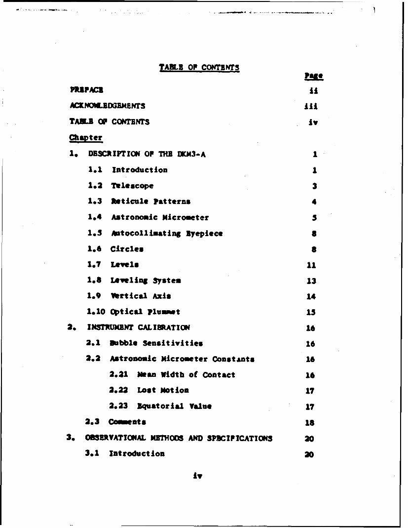
TATL! Of COIn4TINTS
TAM"E OF COMMrw iv
Chapter
1. DESCRIPTION OF THE DKJ43-A 1
1.1 Introduction 1
1.2 Telescope 3
1.3 Faticule Patterns 4
1.4 Astronomic Micrometer 3
1.5 Antocollimating Byepiece 8
1.6 Circles 8
1.7 Levels 11
1.8 Leveling System 13
1.9 Vertical Axis 14
1.10 optical Plummet 15
2. INSTRURMNT CALIBATION 16
2.1 Bubble Sensitivities 16
2.2 Astronomic Micrometer ConstAnts 16
2.21 Mean Width of Contact 16
2.22 Lost Notion 17
2.23 Equatorial Value 17
2.3 Comments is
3. OMSUTVATIONAL MMTHODS AND SPICIPICATIONS 20
3.1 Introduction 20
iv
-t
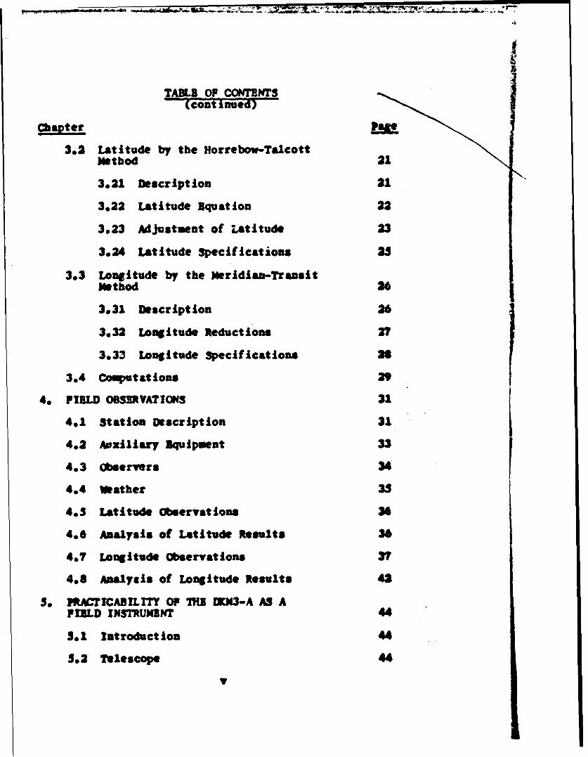
TABLE OP CONTNTS
(coat inaed
ChapterLe
3.2 Latitude by the Horrebov-Talcottm~ethod
3.21 Description 21
3.22 Latitude Equation 22
3.23 Adjustment of Latitude 23
3.24 Latitude specifications 25
3.3 Longitude by the Meridian-TransitMethod 26
3.31 Description 26
3.32 Longitude Reductions 27
3.33 Longitude Specifications 2
3,4 Computations 29
4, FIELD OBSERVATIONS 31
401 Station Description 31
402 Auxillary Equipment 33
4,3 Observers 34
404 Weather 35
4.3 Latitude Observations 36
4.6 Analysis of Latitude Results 36
4.7 Longitude Observations 37
4.8 Analysis of Longitude Results 42
S. PRATICABILITY OF THE IK3-A AS AFIELD INSTRUMENT 44
S.1 Introduction 44
5.2 TelescopeV
TABLE OF CONTENTS(continued)
chapter e
3.3 Pocusing 45
3.4 Astronomic Micrometer 45
5.5 lMorrebow Level System 47
3,6 Leveling Knobs 49
3.7 Setting of Zenith Distances 50
.3.8 Additional Factors and Conclusions 50
6. CONCLUS IONS 52
6.1 Accuracy 52
6.2 Pield Characteristics 52
BIBLIOGRAPHY 53
vi
Chapter 1
DESCRIPTI(iN OF THE [DKM3-A
1.1 Introduction
The DIM3-A is a variant of the Double Circle Trian-
gulation Theodolite D[EM3; the principal changes being
those ve-essary to facilitate the addition of an astro-
nomic micrometer. The Kern Company has continued to
modify the [KM3-A, since it was first made available, in
an attempt to produce an instrument with "first-order"
capabilities, and has recently developed promising new
striding level and double Horrebow level systems.
The Instrument used during this study was purchased
by Ohio State University in 1962 and was originally
equipped with a striding level and a single Horrebow
level that had been designed for the IXDi3. The levels
were relatively insensitive (approximately 44 seconds of
arc per 2 mm division), and tests revealed several other
serious inadequacies. The striding level mount was too
light weight and consequently very unstable. The single
Horrebow level syatem was not heavy enough to properly
counterbalance the astronomic micrometer and when it was
attached, the instruneut could not be properly leveled-
thus making the 1orrebow level usekess.
Immediately prior to this study the Anstrument was
updated by replacing the original striding and Horrebow
levels with the newly developed systems. Detailed
1
2
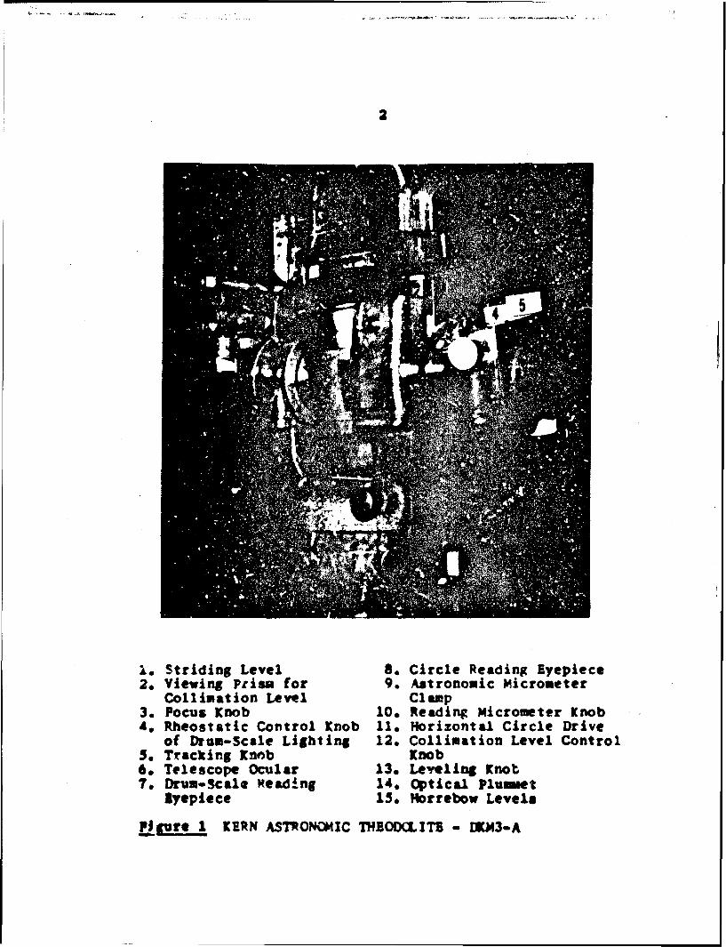
1. Striding Level 8. Circle Reading Eyepiece2, Viewing Prism for 9. Astronomic Micrometer
Collimation Level Cl amp3. Pocus Knob 10. Reading Micrometer Knob4. Rheostatic Control Knob Ile Horizontal Circle Drive
of Drum-Scale Lighting 12. Collimation Level Control5, Tracking Knob Knob6. Telescope Ocular 13, Leveling Knot~7. Drum-Scale Reading 14* Optical plummet
Eyepiece 15. Horrebow Levels
Figure 1 KERN ASTRONC*MXC THBODCLITB - IUCN3-A
3
descriptions of the improved levels are given in Section
1.7. Special low pitch leveling knobs and a single line
tracking wire were also Installed.
This chapter contains a brief description of the
[KM3-A; further Information cia be found in ( 9 ) and
( 10 ). Pigure I is a picture of the Instrument used
during this study.
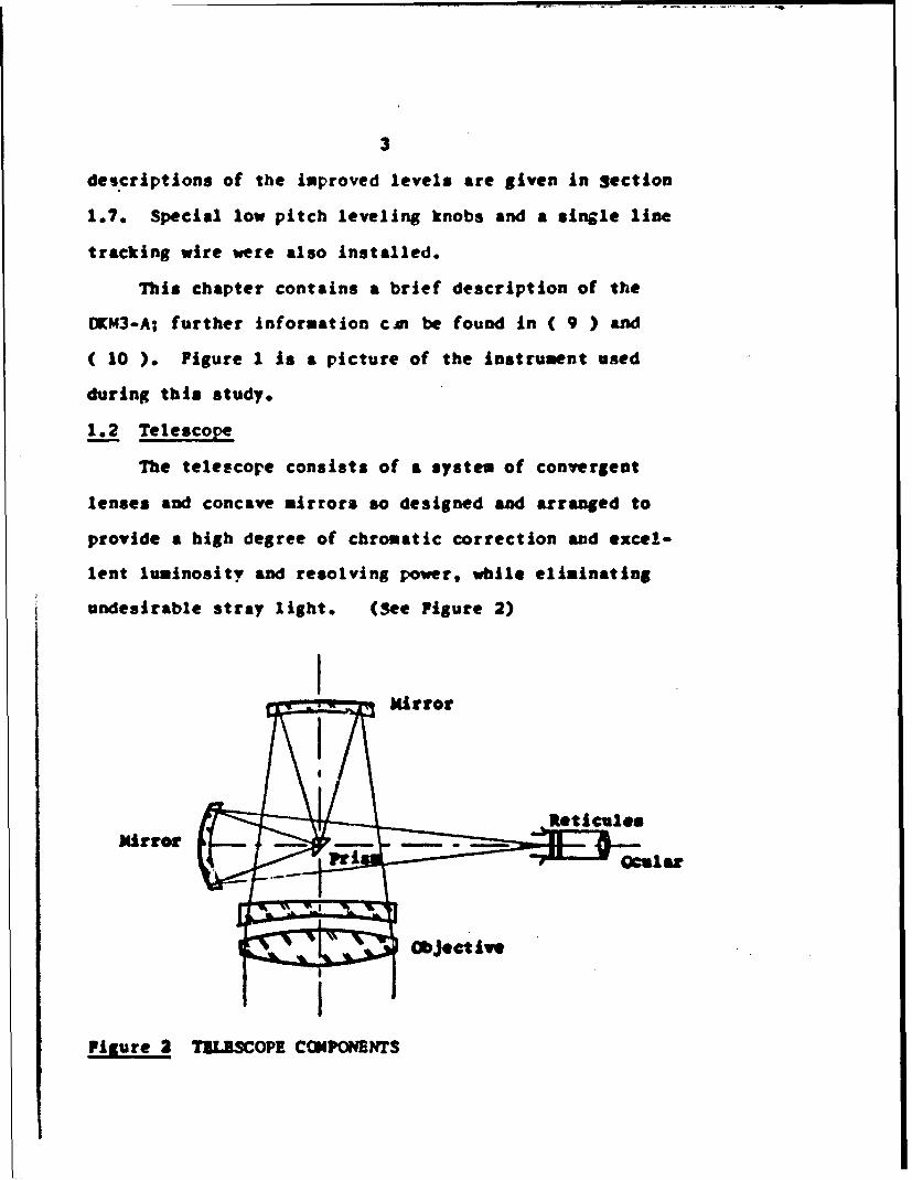
1.2 Telescope
The telescope consists of a system of convergent
lenses and concave mirrors so designed and arranged to
provide a high degree of chromatic correction and excel-
lent luminosity and resolving power, while eliminating
undesirable stray light. (See Pigure 2)
€ • •Mirror
I
MirrorT
Figure 2 TILISCOPE CCIPOI4ENTS
4
The objective lens has an aperature of 72 -m and a
focal length of 510 ma. Two interchangable eyepieces
provide either 45X or 27X magnification. Focusing is
accomplished by a drawtube arrangement controlled by the
focusing screw that moves the entire eyepiece assembly
parallel to the horizontal axis. Focus can be effected
from approximately 19 meters to infinity.
The system is quite adequate to permit the use of
stars as din as 6.0 magnitude for longitude purposes and
7.0 for latitude determinations. Defraction screens are
available for use during observations on bright stars -
such as Polaris.
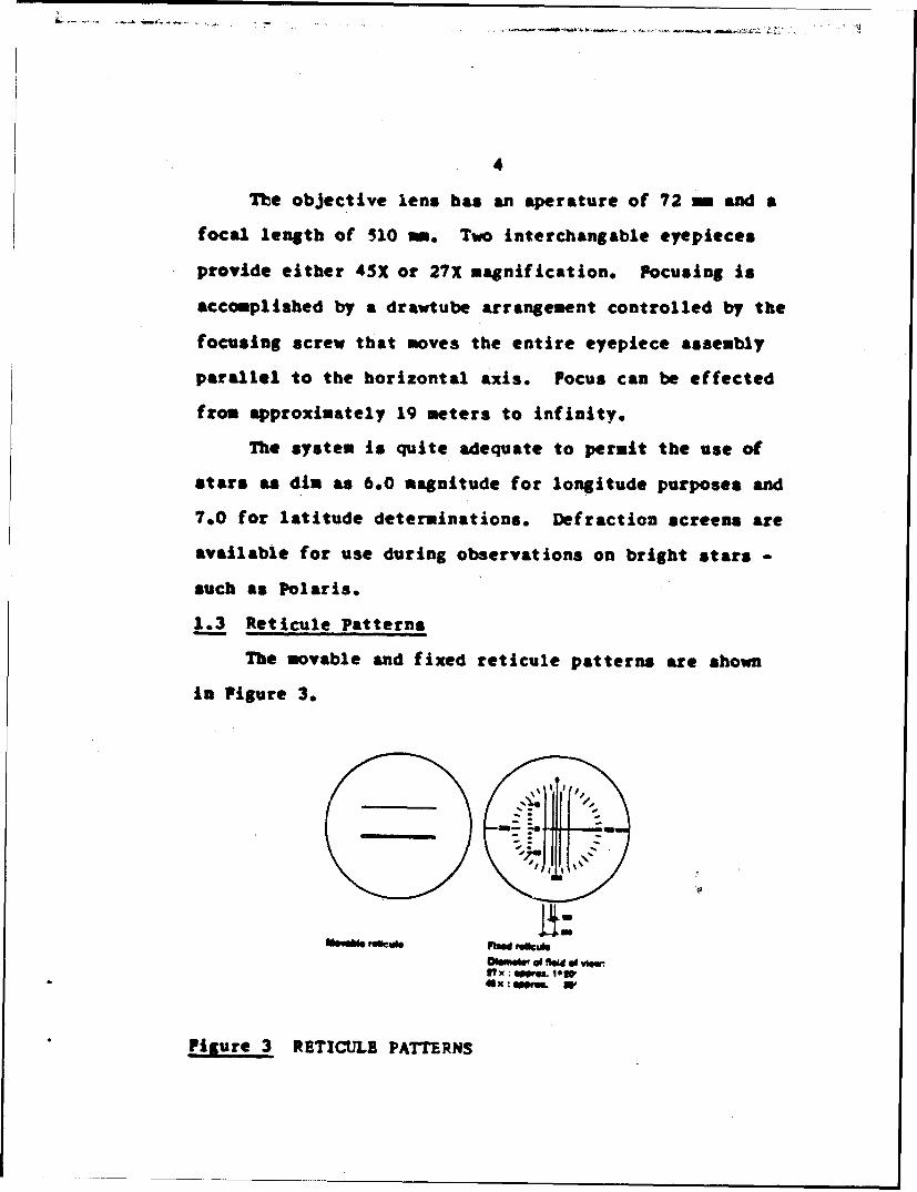
1.3 Reticule Patterns
The movable and fixed reticule patterns are shown
in Figure 3.
1t:
Figure 3 RETICULE PATTERNS
The movable reticule shown here Is of the bifilar
type commonly used in Buropean countries. A single line
type, more often used in the United States Is also avair-
able.
The fixed reticule pattern is a composite of lines
that are used for various purposes. The five parallel
lines are used for observing star transits by the "eye
and ear" method. The ten "tick marks" nuibered from 05
to 15 correspond to whole turns of the micrometer and are
used in conjunction with the movable reticule to measure
azimuth or zenith distance differences. In addition,
there Is a system of azimuth graduations that may be used
to orient the instrument in azimuth so that a particular
star will pass through the center of the reticule - a
condition necessary for certain observations.
1.4 Astronomic Micrometer
The VD63-A Is equipped with an astronomic, or Iw-
personal, micrometer. As usual, the micrometer can be
rotated 90 about its axis to facilitate measurements in
either azimuth or zenith distance. While its basic func-
tions are the same as those performid by any of the tradi-
tional astronomic micrometers, several improvements and
observer conveniences have been incorporated i"to its
design.
The Kern micrometer is completely optically read.
To read the micrometer one first reads the mumber of %bole
S~6
turns from the position of the movable wire in relation
to the fixed field of reticules, and then reads the
fractional part of the turn, or "drum value", through a
special eyepiece located immediately adjacent to the
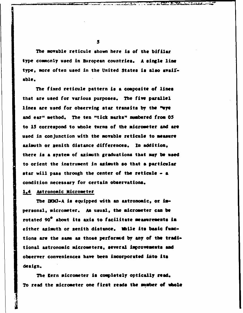
telescope ocular. The drum scale is graduated into 120
divisions and each division is further divided into half.
(See Figure 4) Alternate whole divisions are numbered
from 0 to 118. The system Ji internally lighted, and the
lighting intensity is controlled by a rheostat convenien-
tly located on the micrometer housing.
The resulting effect is to make it quite easy for an
observer to estimate the micrometer value to the nearest
1/10 of a division, which corresponds to approximately
1/10 of a second of arc - equatorial value.
DOnm sle of Vw epc. mteosoWW
Reading: 79.6 d&um unitsI ewakakm - 120'/120 unft
Figure 4 EXAMPLE OF DRUM-SCALE READING
The movable retierle is controlled by two sets of
tracking knobs reciprocally linked and situated at right
angles to one another. Thus, whether the micrometer is
in the azimuth or zenith distance measuring position, and
regardless of the zenith distance at which the measurements
72
S3
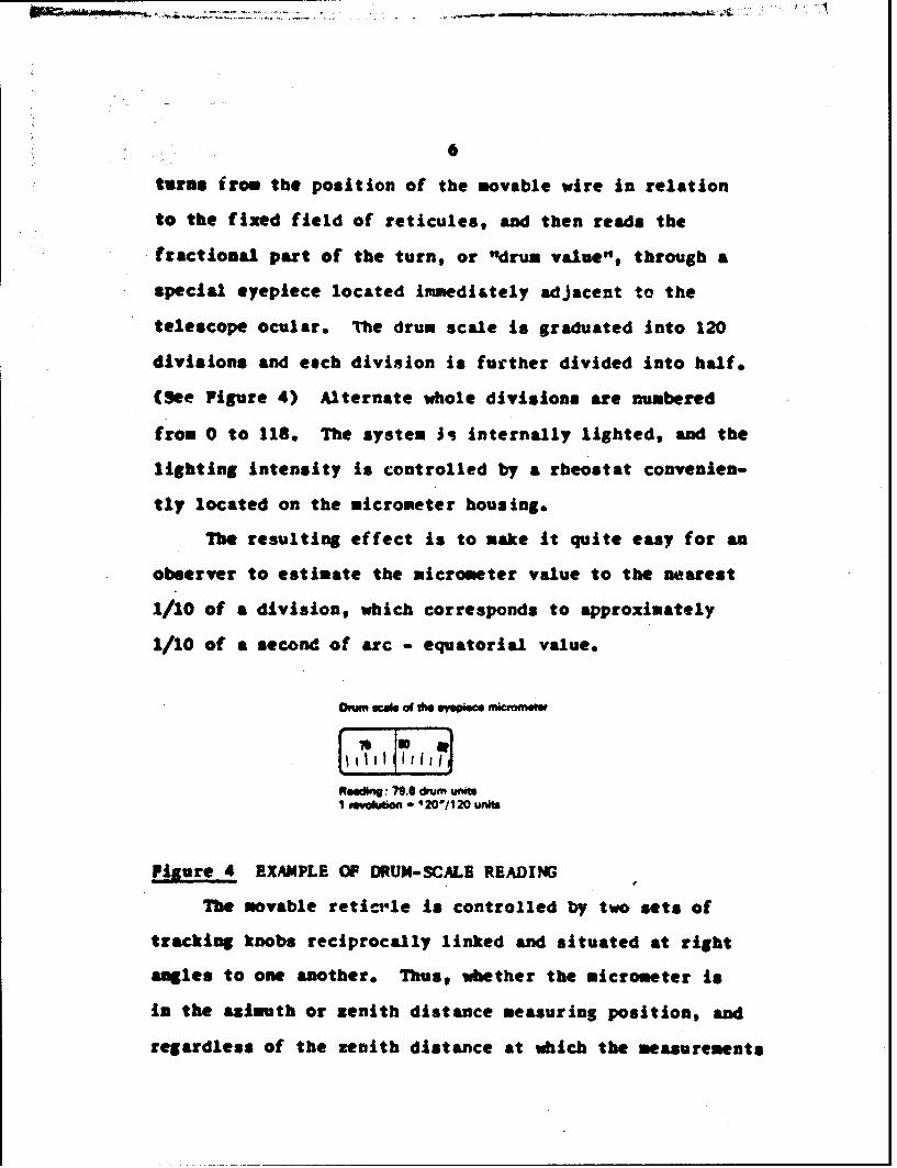
7 6 5 2
I Telecope Eepic2 DrVe Screws Mabe Reuc-le3 Telesco Focusng Scuw wth Ilede for
tIPM Focus4 "v ud CCAl to Chrom.goS U" for Comnmuar Swtchng Lever In the
*On* Puoosm (The Lever 4om not show Intheplr)
6 PAt"Ing Eyepece of Drvm Scae7 Hofing a( Bb for Scae MumwnecmI Reoma for Mjwuni hwe4ty of Sale
Pigure 3 A.fTOMIC HICROITUM
are being made, one set of tracking knobs Is coinveniet.
A plug on the micrometer housing provides the csm
sections for a chronograph cable. In each full turn f
the micrometer ten scaling breks and one ideatificatiom
break are registered. The scaling breaks are very nearly
equally spaced at 12 division intervals, from 0 to I0N
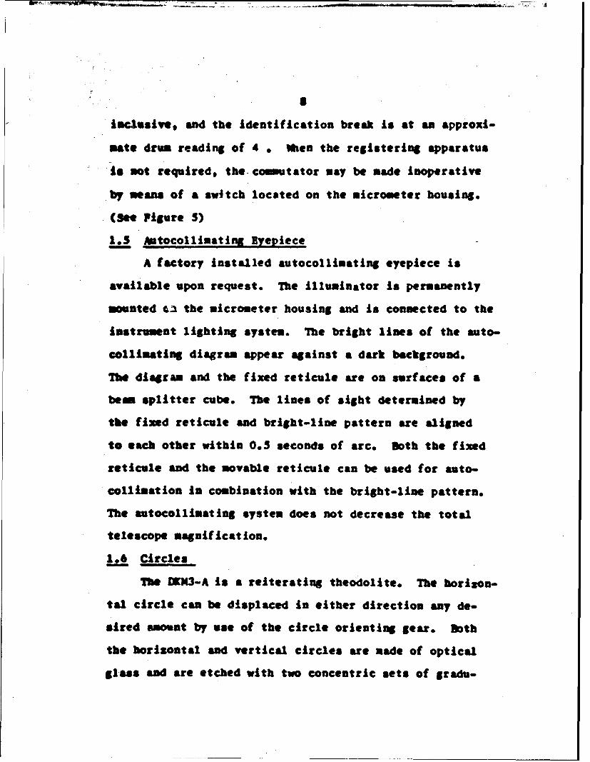
iWclusiVe, and the identification break is at an approxi-
mate drum reading of 4 W Mhen the registering apparatus
is not required, the-commutator may be made inoperative
by means of a switch located on the micrometer housing.
(See Pigure 5)
1.3 bAtocollinating Eyepiece
A factory installed autocollinating eyepiece is
available upon request. The Illuminator is permanently
mounted 6a the micrometer housing and is connected to the
instrument lighting system. The bright lines of the auto-
collimating diagram appear against a dark background.
The diagram and the fixed reticule are on surfaces of a
beam splitter cube. The lines of sight determined by
the fixed reticule and bright-line pattern are aligned
to each other within 0.5 seconds of arc. Both the fixed
reticule and the movable reticule can be used for auto-
collimation in combination with the bright-line pattern.
The autocollinating system does not decrease the total
telescope magnification.
1.6 Circles
The DKN3-A Is a reiterating theodolite. The horizon-
tal circle can be displaced in either direction any de-
sired amount by use of the circle orienting gear. Both
the horizontal and vertical circles are made of optical
glass and are etched with two concentric sets of gradu-
9t
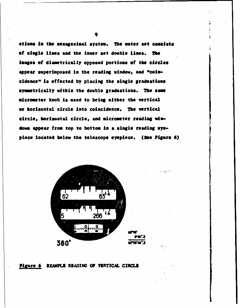
atioms In the sexngesinaJL system. The outer set cossists
of single lines and the inner set double lines. The
Images of diametrically opposed portions of the circles
appear superimposed in the reading winfotw and "coin-
cidence" is effected by placing the single graduations
symmetrically within the double graduations. The som
micrometer knob is used to bring either the vertical
or horizontal circle into coincidence. The vertical
circle, horizontal circle, and micrometer reading via-
dovs appear from top to bottom in a single reading eye-
55
piece located below the telescope eyepiece. (Be. ?igvre 6)
360
Figure 6 B]AWUl PRZADING OF VURTICAL CIVCU
10
7be least graduation value on the circles is 10
minutes. The micrometer has a range of 5 minutes, a
least graduation of 0.5 seconds, and may be estimated to
the nearest 0.1 second. A triangular index appears in
each circle reading window, and is used to read the circle
to the multiple of five minutes next below the exact
reading. The remaining minutes, seconds, and decimal
part of the second are then read from the micrometer,
and added to the above value.
The horizontal circle graduations increase in a
clockwise direction. The vertical circle reads 0e at the
zenith and increases in a counter clockwise direction.
Since the instrument is not equipped with any type of
setting circle, the vertical circle must be used to set
zenith distances. The triangular index may be used to
estimate minutes directly for star pick-up purposes. If
the Instrument is in an ocular east position, the vertical
circle reads zenith distances of south settings directly,
and 3600minus zenith distances for north settings. The
reverse Is true for ocular west. Por precise vertical
circle readings, the vertical collimator bubble must first
be put in coincidence.
Blaborate laboratory tests of the plates, micrometers,
and reading techniques utilized in the DIK3 and subsequent-
ly the IKM3-A, have confirmed the outstanding precision
and consistency of all the mechanical and optical
components CS)and ( 11 )
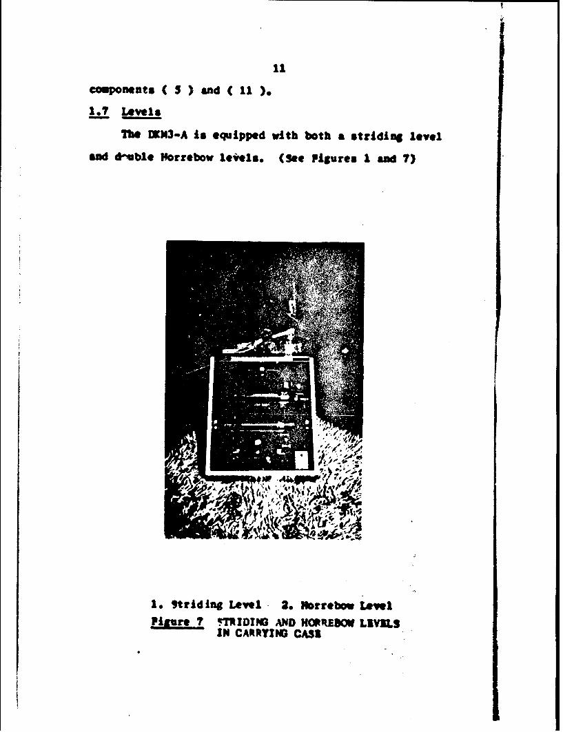
1.7 Levels
The CKM3.A is equipped with both a striding level
and duvble Morrebow lewils. (Sao Figures I and 7)
1. "trid ing LvewI 1. Irrebow wIAPlU!LZ QTR1D1YG AND HOPREDOW LIVILS
IN CARPYING CASI
12
The striding level is not set directly on the hori-
zontal axis, but is supported by two seats that ate
parallel to the axis and rigidly attached to the stand-
ards. The level is heavily weighted for stability, and
can be placed on the instrument in only one position,
i.e. the level cannot be reversed on the seats. A center-
ing adjustment screw is conveniently located at one end
of the vial housing. The striding level cannot be used
during Horrebow-Talcott latitude determinations because
it Interfers with the viewing of the Horrebow levels.
The Horrebow levels are designed to be attached
only after the instrument has been set up. A counter
weight is attached to the instrument during shipment,
and must be removed before the Horrebow levels can be
mounted. Three screws connect the Horrebow mount to the
instrument directly opposite the observing ocular. The
babbles may be clamped to the horizontal axis with the
telescope in any position and a slow motion tangent is
provided for final adjustment. One bubble mount is
provided with a centering adjustment screw to facilitate
alignment of the two bubbles. The entire bubble mount
must be removed in order to adjust the bubbles, lengths.
The vials used in both the striding and Horrebow
levels are of the chamber type and have sensitivities
of approximately 1.5 seconds of arc per 2 -m division.
13
There are approximately 40 viewable divisions and every
fifth division is numbered in a continuous scheme through-
out the length of the vial. The striding level's numbering
increases toward the observing ocular. one of the Horrebow
level's numbering is biased by 100 to eliminate any
confusion in readings, and the numbering Increases from
the observer's right to left, ioe. ocular eat, the
maximum values are to the south. The bubbles are all read
as reflected Images viewed in overhead mirrors. Lighting
units are available for both the striding and Horrebow
levels.
The instrupent is further equipped with a plate
level with a sensitivity of approxitnately 10 seconds of
arc per 2 mm division and a graduated collimation bubble
for which vials with sensitivities from approximately
10 to 2,5 seconds of arc per 2 = division are avaylabie.
The collimation bubble Is viewed a a split Iiage in a
rotatable prism mounted at the top of the standard near-
est the observer, and is brought into coincidence by use
of the collimation level slow notion screw.
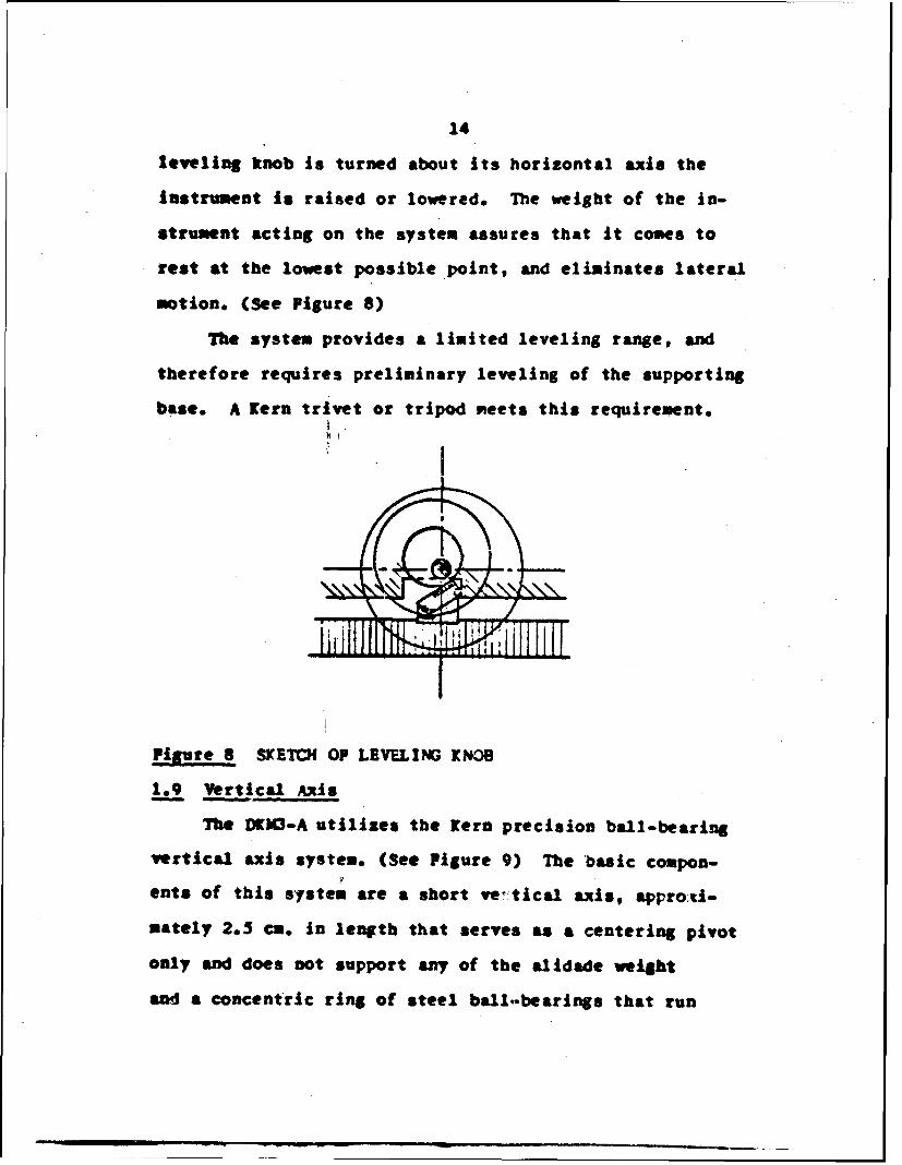
1.8 Leveling Systen
The ION3-A eliminates amay of the instabilities
inherent in leveling screws by the use of Itern's system
of leveling cans. A cam on the intersurf ace of each
leveling knob bears on the incliaed supporting surface of
a boss provided on the Instrument's anchor plate, Ao the
14
leveling knob is turned about its horizontal axis the
instrument is raised or lowered. The weight of the In-
strument acting on the system assures that it comes to
rest at the lowest possible point, and eliminates lateral
notion. (See Figure 8)
The system provides a limited leveling range, and
therefore requires preliminary leveling of the supporting
base. A Kern tr vet or tripod meets this requirement.
Figure 8 SKETCH OP LEVELING KNOB
"1.9 Vertical Axis
The DKX3-A utilizes the tern precision ball-bearing
vertical axis system. (See Figure 9) The basic compon-
ents of this system are a short vetical axis, approcl-
mately 2.5 ca. in length that serves as a centering pivot
only and does not support any of the alidade weight
and a concentric ring of steel ball-bearings that run
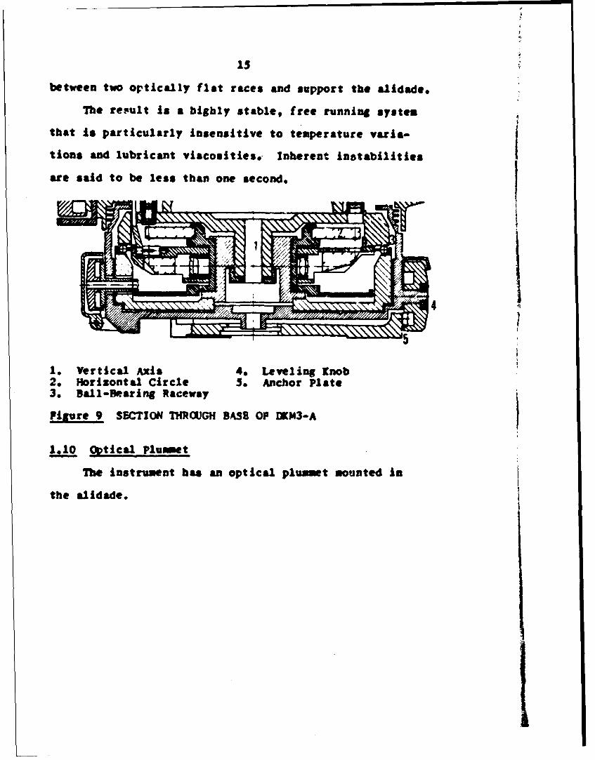
between two ortically flat races and support the alidade,
The re.sult is a highly stable, free running system
that Is particularly Insensitive to temperature varia-
tions and lubricant viscosities, Inherent instabilities
arte said to be less than one second.
-I
1. Vertical Axis 4. Leveling Knob2. Horizontal Circle 5. Anchor Plate3. Ball-Bearing Raceway
Pigure 9 SECTION THROUGH BASS OP MKM3-A
1,10 Optical Plummet
The instrument has an optical plummet mounted in
the alidade.
Chapter 2
TWITRUMENT CALIBR •T!ON
2.1 Bubble Sensitivities
The striding level and Horrebow levels bubble vials
sensitivities were determined by Kern's Port Chester,
New York, office at the time of their installation
approximately one week before the beginning of this study.
The calibrations were made against the instrument's
vertical circle, and the final accepted value is the
result of a series of 5 determinations ( 22 ). The
sersitivities per division were found to be:
Striding level I'6 t O•0O
Horrebow levels 13 * OVlO1V4 Or0lO
2.2 Astronomic Micrometer Constants
The astronomic micrometer was examined to determine
the "mean width of contact", the "lost notion", and the
"equatorial value".
2.21 Mean Width of Contact
The contact strips used in the astronomic micrometer
time recording apparatus have finite widths that cannot
be considered negligible for precise time determinations.
The individual widths do not vary significantly and a
mean value may be used to make the necessary correction.
A mean width determination was made in the field
during the process of this study. The results of 10 sets
16
1?
of measurements, each set consisting of a reading of the
width of each of the 10 contacts, yielded a mean width
of 0.713 & .008 drum divisions.
2.22 Lost •otion
If the movable wire is set on some fixed object such jas the 10 line of the fixed reticule, once by approaching
it from lesser values and once from greater values, the
two readings will not be identical. The absolute differ-
ance of the readings is defined to be the lost motion of
the micrometer.
The lost notion Is thought to be effected by the
position of the movable wire within the field of view
and the position of the telescope in zenith distance.
The DK3.-A is satisfactorily equipped for lost motiom
determination only at the center of the field- at the
10 wire.
For the purpose of this study the lost motion was
evaluated for zenith distances of 45% 30e and 0*.
(vertical circle settings of 45, 301f, 0*. 330', 31?°)
Bach determination consisted of a set of 10 readings.
Variations in the lost motion were small and yielded a
man lost notion of 0.244 1 .008 drum divisions.
2,23 Equatorial Value
TIe OWM3-A's astronomic micrometer was designed te
have an equatorial value of one turn of approximately two
. 18
minutes of arc or a seconds of time. Each instrument
will have a slightly different value and the value for
any particular Instrument will change slightly with changes
in focus. For this reason, a best fitting equatorial
value Is computed as part of the least squares adjustment
of each latitude determination by tne Horrebo-.Talcott
method.
The equatorial value for the instrument used during
this study, as derived from the latitude observations,
is approximately 118."5 or 799.
2.24 Comments
The micrometer has a rather large amount of lost
motion which is usually considered undesirable.
Hoskinson and Duerksen ( 7 ) warn that the lost motion
may vary unpredictably within the field of view, and
it is possible that the "stationary lost motion"
(determined here) may differ from what might be called
the "dynamic" lost notion - this being the lost notion
at a point when the screw is rotating rapidly enough
for star tracking.
It continues that if the stationary lost action is
nearly zero it is probable that the effect of dynamic
lost motion may be ignored, but if this condition Is not
met, it may be necessary to determine the dynamic lost
motion through much more elaborate procedures. Such an
19
lnveStigation is outside the scope of this field study,
but it Is mentioned here as a possible source of nicro-
meter error.
Chapter 3
OBSERVATIJNAL METHODS AND SPECIFICATIONS
3j.In troduction
At present there are several U.S. Government Agencies
doing precise astronomic latitude and longitude deternin-
ations through out the world. While each such organiza-
tion may have slightly varying techniques and specifica-
tions that define various accuracy classifications, the
differences are usually insignificant and in general one
cam group such observations into one of the three following
categories - "first-order,,, "modified-first-order",
"*second-order",
The less precise second-order methods usually do not
require an instrument equipped with an astronomic micro-
meter and are well suited to Instruments such as the Wild
T-3 or the Kern [K4-3 theodolites. Several second-order
methods are described in detail in ( 4 ) and ( 13 ).
The more precise first-order and modified-first-order
position determinations depend on the Horrebow Talcott
latitude method and the Meridian-Transit longitude method.
Both observations require the use of an astronomic
micrometer and special highly sensitive level systems
usually found only on instruments specifically designed
for such work.
The following sections give a brief description of
the first-order and modified-first-order procedures and
20
21
the specifications followed during the observing and
computing facets of this study.
3.2 Latitude by the Horrebow-Talcott Method
3.21 Description
The Horrebow-Talcott method for precise latitude
determination consists of measuring the difference in
meridian zenith distance of two stars at nearly equal
altitudes and right ascensions that culminate on
site sides of the zenith. The small difference in
zenith distances is measured by an astronomic mictometer,
and Horrebow levels provide a measurement of amy meri-
dional inclination of the Instrument during the obsetv-
ing period.
The latitude of the observing station is the mean
of the declinations of the two stars plus the algebraic
sm of one half of the observed micrometer difference,
one half of the difference in meridional inclination of
the collimation axis during the observations, and one
half of the difference in refraction of the two senith
angles. If either or both of the start Is observed prior
to or after culmination a correction tere mut be applied
to reduce the observation tO the meridian.
Th USMIS adopted the Norrebow-Talcott method as
their standard of latitude determination in 1851, wn a
detailed account of their observational techniques and
computations are presented in ( 7 ).
22
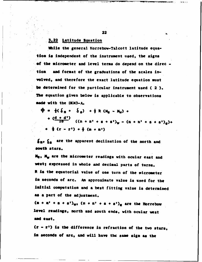
3.22 Latitude Nquation
While the general Horrebow-Talcott latitude equa-
tion is independent of the instrument used, the signs
of the micrmter and level terns do depend on the direc
tion and format of the graduations of the scales in-
volved, and therefore the exact latitude equation must
be determined for the particular Instrument used ( 2 ).
T7e equation given below is applicable to observations
made with the IKN3-A.# IS # • .) + I i (m, - M.) ÷0
( * ( d) ((n * n' # s o s9 *)- (* * n' 4 ',* I (r - ') ÷ I(m ÷')
a •e are the apparent declination of the north and
South stars.
e, Nw are the micrometer readings with ocular east and
west; expressed in whole and decimal parts of turns.
R is the equatorial value of one turn of the micrometer
in seconds of arc. An approximate value is used for the
niitial computation and a best fitting value is determined
as a part of the adjustment.
(S + a' + 6 + S')wt (n + n' # 8 * S')* are the Horrebow
level readings, north and south ends, with ocular west
sad east.
(r r- ) Is the difference in refraction of the two stars,
Is seconds of arec, and will have the same sign as the

23
micrometer correction. Tables VIII, VI, and VII of ( 7 )
may be used to compute the magnitude of the correction.
(a + in) is the sun of the meridian corrections and is
applied only if one or both of the stars are observed
prior to or after transit. It can be directly inter-
polated from Table X of ( 7 )o
d, d' are the sensitivities in seconds of arc of each
Murrebow level per division.
3 Adjustment of Latitude
Individual latitudes differing from the mean lati-
tude by more than 3VO are first rejected. After a new
mean latitude, corresponding residuals, and the probable
error of a single observation, ep, have been computed,
each remaining observation is examined for possible re-
jection due to an abnormally high residual to ep ratio.
Chauvenet derived a set of rejection limits based on the
anmber of observations and the residual to or ratio from
the theory of least squares. Their applications are
described in detail in ( 7 ). Based on his work, the
following rejection criteria have generally beet accepted
as valid wben the mmber of observations Is approximately
2O or more. Any observation witb a residual greater tham
Sep is automatically rejected. In additiom, 3§ep is used
as a doubtful limit and if additional evidence indicates
that an observation's validity Is questionable, such au
an observer's field note, contradictions in thU field
24
records, or a large probable error of one or both of the
stars'declinations as tabulated in the star catalogue,
the observation should be rejected. Por fewer observa-
tions, refer to "Reduction of Doubtful Observations" page
136 of ( 7 ).
Subsequent to the above rejections and prior to the
final adjustment the algebraic sun of the micrometer
differences must be checked to see that it is less than
the total number of acceptable pairs. If not, additional
star pairs must be rejected on the basis of largest
number of micrometer turns and maximum residuals until
a sufficent balance is effected.
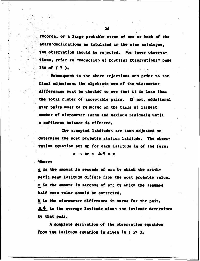
The accepted latitudes are then adjusted to
determine the most probable station latitude. The obser-
vation equation set up for each latitude is of the forms
C -Mr. A€=v
Utret
c is the amount in seconds of arc by which the arith-
metic mean latitude differs from the most probable value.
r is the amount in seconds of arc by which the assumed
half turn value should be corrected.
N is the micrometer difference in turns for the pair.
A_ is the average latitude minus the latitude determined
by that pair.
A complete derivation of the observation equation
from the latitude equation is given in ( 17 ).
25
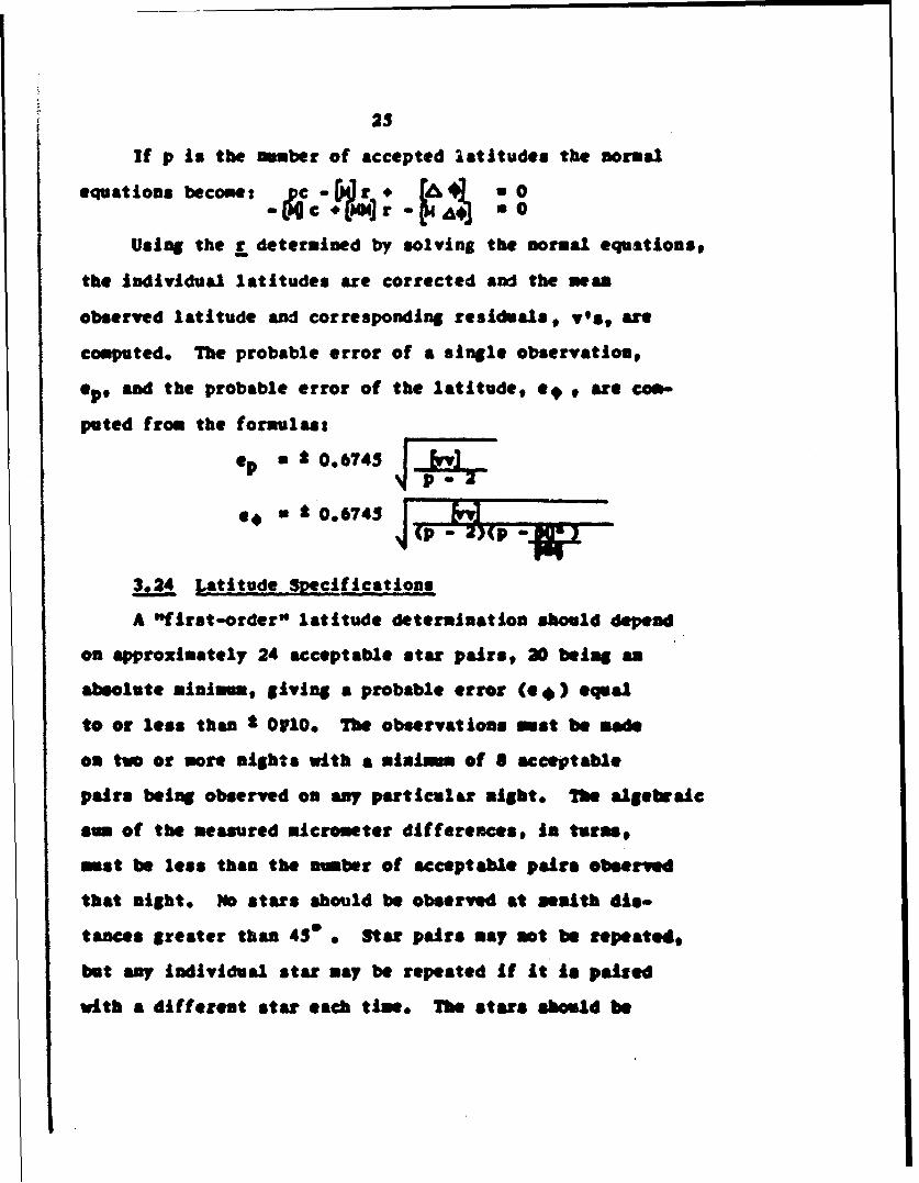
If p Is the amber of accepted latitudes the normal
equations become: Ac(r, 4I .
Using the _ determined by solving the normal equations,
the individual latitudes are corrected and the wean
observed latitude and corresponding residuals, vest are
computed. The probable error of a single observation,
ep, and the probable error of the latitude, e 9 , are com-
puted from the formulast
ep * 0.6745
* * 006745
3.24 Latitude Specifications
A "first-order" latitude determination should depend
on approximately 24 acceptable star pairs, 20 being an
absolute minimu, giving a probable error (e $) equal
to or less than I OVlO, The observations must be wade
on two or more nights with a minimum of $ acceptable
pairs being observed on any particular night. The algebraic
sum of the measured micrometer differences, in turns,
must be less than the number of acceptable pairs observed
that night. 1o stars should be observed at wealth dis-
tances greater than 453 Star pairs way not be repeated,
but any individual star nay be repeated if it is paired
with a different star each time. The stars should be
26
.selected from a general star catalogue sach as ( 3 ),
A "modified first-order" latitude determination
.should depend on approximately 16 acceptable star pairs,
12 being an absolute minimum, requiring only one night's
observations with a maximum probable error of O 0M'0 or
* 0V25. All other specificstA.ir.s are the same as for
"first-order" determinations.
A Lonsitude by the Meridian-Transit Method
3.31 Description
The determination of an observer's longitude con-
sists of measuring the difference between the Local
Sidereal Time (LST) at the observer and the Greenwich
Sidereal Time (GST) at the same instant. The GST is
readily attainable in the form of Universal Time, from
various radio time signals, and the LST can be deter.
mined by observing the meridian transit times of stars-
at the instant of transit the LST is equal to the star's
right ascension.
In practice, some value Is assumed for the observer's
longitude and a sidereal chronometer is set to the corres-
ponding LST. The difference between this assumed LST
and GST is checked at frequent Intervals to determine
the chronometer's correction and rate. The transit times
of a number of stars are then recorded in reference to
the assumed LST. Any difference between the observed
time of transit (recorded time of transit corrected for

II
27
instrumental constants, instrument dislevelment, and
diurnal aberation) and the apparent right ascension of
the star consists of a correction to the assumed long-
itude and a reduction to the meridian. A set of such
star observations, selected to fulfill certain specifi-
cations, (See 3.33) constitutes one longitude determin-
ation or meridian transit.
3.32 Longitude Reductions
An observation equation of the forms
AXk- A& + (a I-t -At) a v
is formed for each star and a least squares edjustnent Is
performed to determine the best fitting AA and s for each
set.
Wwres
AA. is the correction to the assumed longitude.
a is the simuuth of the instruments collimation
axis during the observations. (reduction to neridian)
CC is the apparent right ascension of the star.
A is the star asimuth factor and can be directly
interpolated from Table III ( 7 )0
t is the observed time of transit.
At is the chronometer correction.
AMy star yielding a Akthat is greater than 092
from the set's mean is rejected. The probable error of
AA as determined by a single star, es, sad the prob-
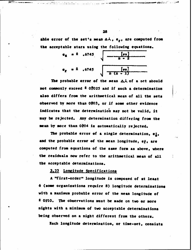
28
able error of the set's mesan AA., er, atre computed from
the acceptable stars using the following equations.
* e~~~U * ~*6743 ________
Or - .6743 J -The probable error of the mean Ak of a set should
not commonly exceed 2 0.8025 and if such a determination
also differs from the arithmetical mean of all the sets
observed by more than 0103, or If some other evidence
indicates that the deterninatio, may not be valid, it
may be rejected. Any determination differing from the
mean by more than 0104 Is automatically rejected.
The probable error of a single determination, *1,
and the probable error of the mean longitude, ei, are
computed from equations of the same form as above, where
the residuals now refer to the arithmetical mean of all
the acceptable determinations.
3.33 Longitude Specifications
A "first-order" longitude is composed of at least
6 (some organizations require 8) longitude determinations
with a maximum probable error of the mean longitude of
t OIO. The observations must be made on two or more
nights with a minimum of two acceptable determinations
being observed on a night different from the others.
Bach longitude determination, or time-set, consists
of from $ to 8 acceptable stars bracketed by radio
chronometer comparisons, The stars should be as evenly
distributed north and south of the zenith as possible*
An acceptable S star set must contain 2 north (south)
and 3 south (north) stars. The selected stars should
have a maximum A-factor of 2 0.060 and the algebraic sum
of the A's for any determination should not exceed 1 1.00,
The instrument should be within 1*80 (a) of the meridian
throughout the observations. At least 10 breaks before
transit and the corresponding breaks after transit whose
sums do not vary more than OIN are required for an accept-
able star track. The stars are selected from the
Apparent Places of Pundamental Stars - P14 star catalogue.
lach radio-chronometer comparison should be the
result of about 20 scaled radio breaks and the decimal
portion of any particular break should not vary from the
mean by more than OfOS.
A "modified first-order" longitude is composed of
at least 3 (4 being more desirable) determinations with
a maximum probable error of the mean longitude of * O o.
All of the observations may be performed during one slogt,
All other apecif•ications are the sow as the "first-order"
determinations.
3.4 Comuatations
All of the latitude and longitude observations MMe•
during this study were computed by the 1381st OSS0s
30
electronic computer using the same programs they developed
to reduce their precise position observations. The re-
Joictions of doubtful observations and the final adjust-
meats wre done by hand, following the procedures pre-
viously outlined,
CH AMTR 4
FIELD OBSERVATIONS
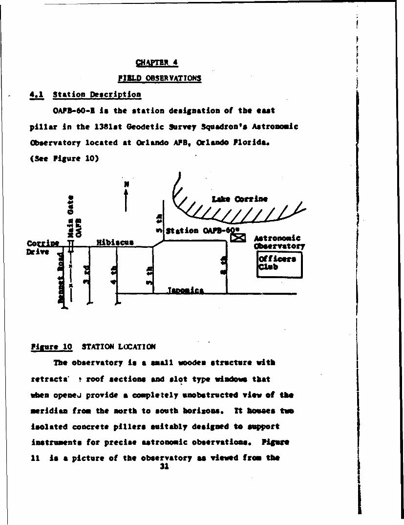
4.1 Station Description
OAFB-60-2 is the station designation of the eat
pillar in the 1381st Geodetic Survey Squadron's Astronomic
Observatory located at Orlando APB, Orlando Florida.
(See Figure 10)
* t / Lake ~
0 ACt at Io
IT Hibiscus ' , [4 Astronomic
Drive Obsera ory
I -t
Figure 10 STATION LOCATION
The observatory is a small wooden structure with
retracts' t roof sections and slot type windows that
when openei provide a completely unobstructed view of the
neridian from the north to south horizons. It houses two
isolated concrete pillers suitably designed to support
instruments for precise astronomic observations. Piuwe
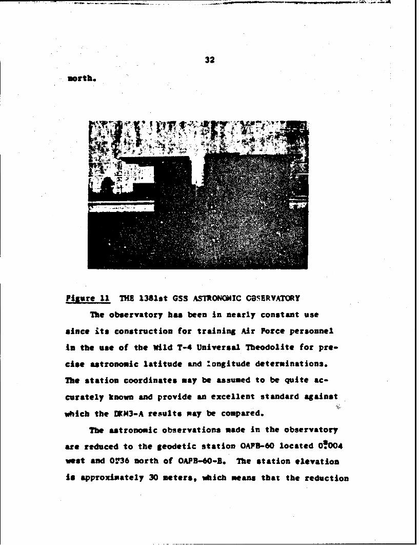
11 is a picture of the observatory as viewed from the31
32
morth*
Figure 11 THE 1381st OSS ASTRONOMIC OBSERVATORY
The observatory has been in nearly constant use
since its construction for training Air Porce personnel
to the use of the wild T-4 Universal Iteadolite for pre-
cis* astronomic latitude and !ongitude determination3.
The station coordinates may be assumed to be quite ac-
curately known and provide an excellent standard against
which the DWN3-A results may be compared.
The astronomic observations made In the observatory
art reduced to the geodetic station OAFS-6O located 0!004
wast and 07'36 north of OAFS-GO-E. The station elevation
Is approximately 30 meters,, which means that the reduction
33
to the geold may be considered to be zero. The astro-
nomic coordinates of station OAFS-60 are:
Latitude 28 34' 031?60 North
Longitude 0 5 h 20 27t355 Wst
The latitude refers to the 3.1.1. pole. The longitude
is refered to the UT2 time system, and includes a
correction to reduce it to the prior 1960 WWr system.
(See Section 4.7)
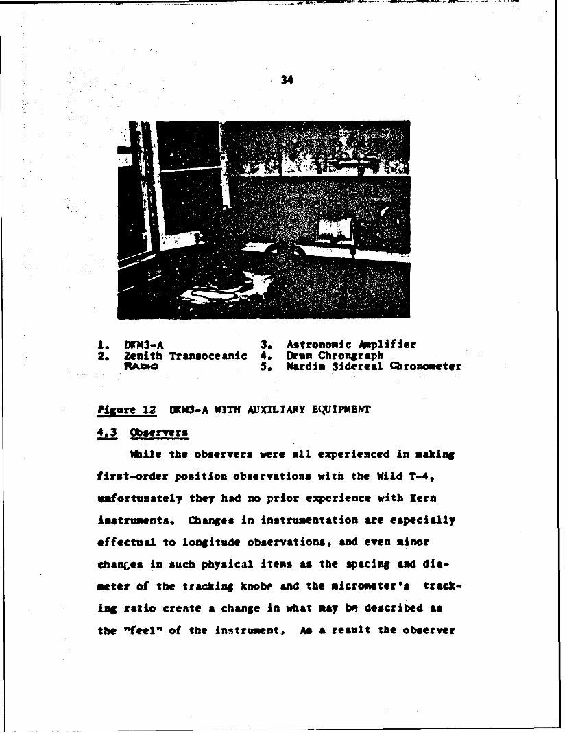
4.2 Auxiliary Equipment
All of the equipment used during the field observa-
tions, other than the DIKM3-A, belongs to the 1381st GSS.
The equipment was purchased specifically for precise
astronomic work and is of the highest quality.
A Nordin two-second break circuit sidereal chronometer,
electric drum type chronograph and an astronomic amplifier
were used for recording the time signals and times of
star transits for longitude observations. A Zenith
Transoceanic radio was used to receive the radio time
signals. A tapeing thermometer and a pocket barometer
provided field temperatures and barometric pressures,
and the readings *ere checked frequently against those
obtained from the McCoy APB weather station.
(See Figure 12)
34
1. NM3-A 3. Astronomic Amplifier2. Zenith Transoceanic 4. Drum Chrongraph
RJ eo 5. Nardin Sidereal Chronometer
PFiure 12 DKM3-A WITH AUXILIARY ()UIPMENT
4.3 Observers
%bile the observers were all experienced in making
first-order position observations with the Wild T-49
ufortunately they had no prior experience with Kern
instruments. Changes in instrumentation are especially
effectual to longitude observations, and even minor
chanes in such physical items as the spacing and dia-
meter of the tracking knobe and the micrometer's track-
ing ratio create a change in what may be described as
the "feel" of the Instrument, As a result the observer
35
may find it difficult to track a star as smoothly 6i
normal, and the accuracy of the time of transit becomes
qsestionable. Readings from the unfamiliar plates and
microneter are also more prone to errors.
The time available for the field work portion of this
study was limited and bed weather further restricted the
number of observations that could be accomplisbed. The
result was that the observers had only the most limited
time in which to become familiar with the K3-A, and
some of the first longitude star tracks were rather
inconsistent. As the observers experience with the
instrumet increased, the works consistency also increased.
4 Weather
The weather was a significant factor during this
study. The observations were begun on the 31st of hbgust
1964 and there followed about one week of fairly clea
weather in which 3 first-order latitudes and 2 first-
order longitudes were observed. During this tim a large
hurricane, Diane, was approaching the station from very
nearly due eat, and on the loth of September passed Juot
north of Orlando bringing winds in excess of 80 miles
per bour and over S inches of rain to tt•e area. sesrv&-
tions were resumed on the 13th, but the weather costimned
to be rather unstable throughout the remaining observatines
It is very difficult to determine Just what effect
the approach or retreat of such severe weather could have
36
an astronomic observations. It is known that the
phenomenon known s a "tilted atmosphere" (tilted isotherns,
isobars, air densities) can cause significant local
lateral refraction and ( I ) has recorded correlation
between wind conditions and apparent changes of longitude.
Estimations of the magnitude of such atmospheric effects
vary greatly with investigators.
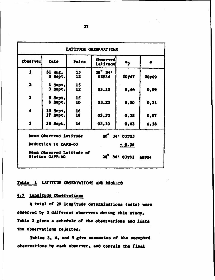
4 Latitude Observations
A total of 4 first-order and one modified-first-order
latitudes were observed by $ different observers. The
results are tabulated in Table 1 The mean observed
latitude was computed using a weight of for each
determination.
4.6 Analysis of Latitude Results
The latitude determinations are what might be described
as "typical" Horrebow Talcott latitude observations. The
maximum variation in the final observed latitudes, uncor-
rected for polar motion, is 0124. The mean correction
to the provisional B.I.H. pole ( 23 ) over the period of
these observations was approximately * 0U02. If the
correction is added to the mean observed latitude, the
final mean latitude becomes 28° 34' 03V63. The latitude
"as determined by the IXN3-A agrees with the station
latitude, as determined by the T-4, and it seems likely
that no "instrument equation" exists between the two
instruments.
37
LATIThD OBSERVAT IONS
Observer Date Pairs ObservedLatitude op 0
1 31 Aug IS 28 34'2 Sept. 12 03,34 t 0?47 20109
2 I Sept. is3 Sept* 12 03.10 0.46 0.09
3 $ Sept. 156 Sept. 10 03.22 0.50 0.11
4 13 Sept* 1617 Sept, 16 03.32 0036 0.07
$ 18 Sept. 16 03.10 0063 0.16
Mean observed Latitude 21f 34' 03V25
Reduction to OAPD-60 * 0,.36
Mean Observed Latitude ofStation OAPB-60 28 349 03.l S0V04
Table I LATITUDE OBSRVATIOES AND RISULTS
4t? Longitude Observations
A total of 29 longitude determination* (sets) were
observed by 3 different observers during this study.
Table 2 gives a schedule of the observations and lists
the observations rejected.
Tables 3, 4, and 5 give suszies of the accepted
observations by each observer, and coatain the fimal
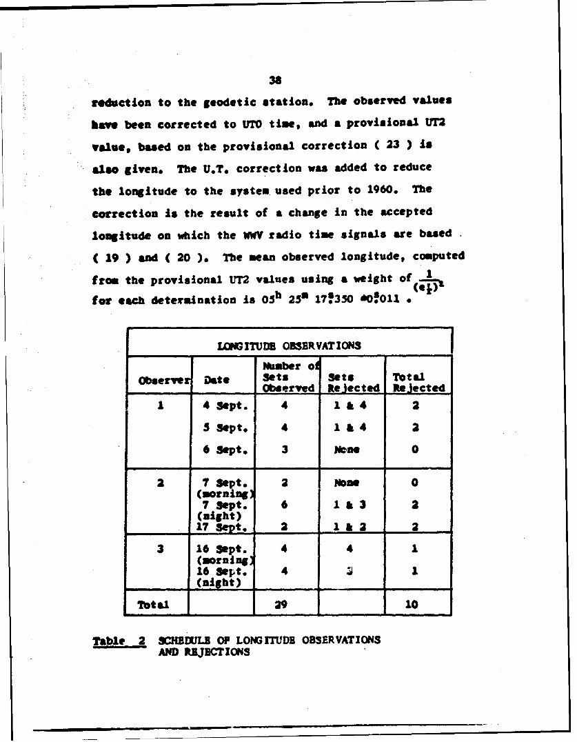
38
reduction to the geodetic station. The observed values
hoVe been corrected to UTO time, and a provisional UT2
value, based on the provisional correction ( 23 ) is
also given. The U.To correction was added to reduce
the longitude to the system used prior to 1960. The
correction is the result of a change in the accepted
longitude on which the WV radio time signals are based
( 19 ) and ( 20 ). The mean observed longitude, computed
from the provisional UT2 values using a weight of
for each determination is 05h 250 17!350 *0ll * (e,)
LOWGM rU OBSERVATIONS
Number olObserve Date Sets Sets TotalODaerved Rejected Rejected
1 4 Sept. 4 1 & 4 2
3 Sept, 4 1 & 4 2
6 Sept. 3 None 0
3 7 Sept. 2 None 0(morning)7 Sept. 6 1 & 3 2
(night)17 3VSept. 2 •&2 2
3 16 Sept. 4 4 1(morning)16 Sept. 4 1 1(night)
Total 29 10
Table 2 SCHBI.JLB OP LOPGITUDB OBSERVATIONSAND R.JBCTIONS
39f
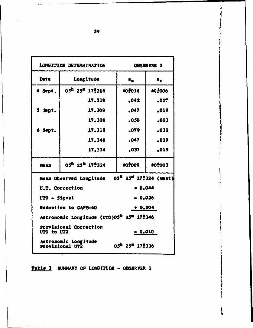
i
LONGITUDE DETERMINATION OBSERVER 1
Date Longitude *a Or
4 Sept. 0 5 h 25m 178316 *01016 *C!O06
17.319 e042 .017
$ Jept. 17.309 .047 o019
17.326 .050 .023
6 Sept. 17.318 .079 .032
17.346 .047 .019 117,334 .037 .015
Mean 0 3h 250 17f324 2018009 *.003
Mean Observed Longitude 0 5 h 25m 17!324 (West)
U.T. Correction * 0.044
Ut7o - Signal - 0.026
Reduction to OAPD-60 09004
Astronomic Longitude (UTO)OSh 250 171346
Provisional CorrectionUTO to UT2 .- 0010
Astronomic LongitudeProvisional UT2 0 5 h 25m 171336
Table 3 SUMMARY OF LONGMITUR - OBSERVER I
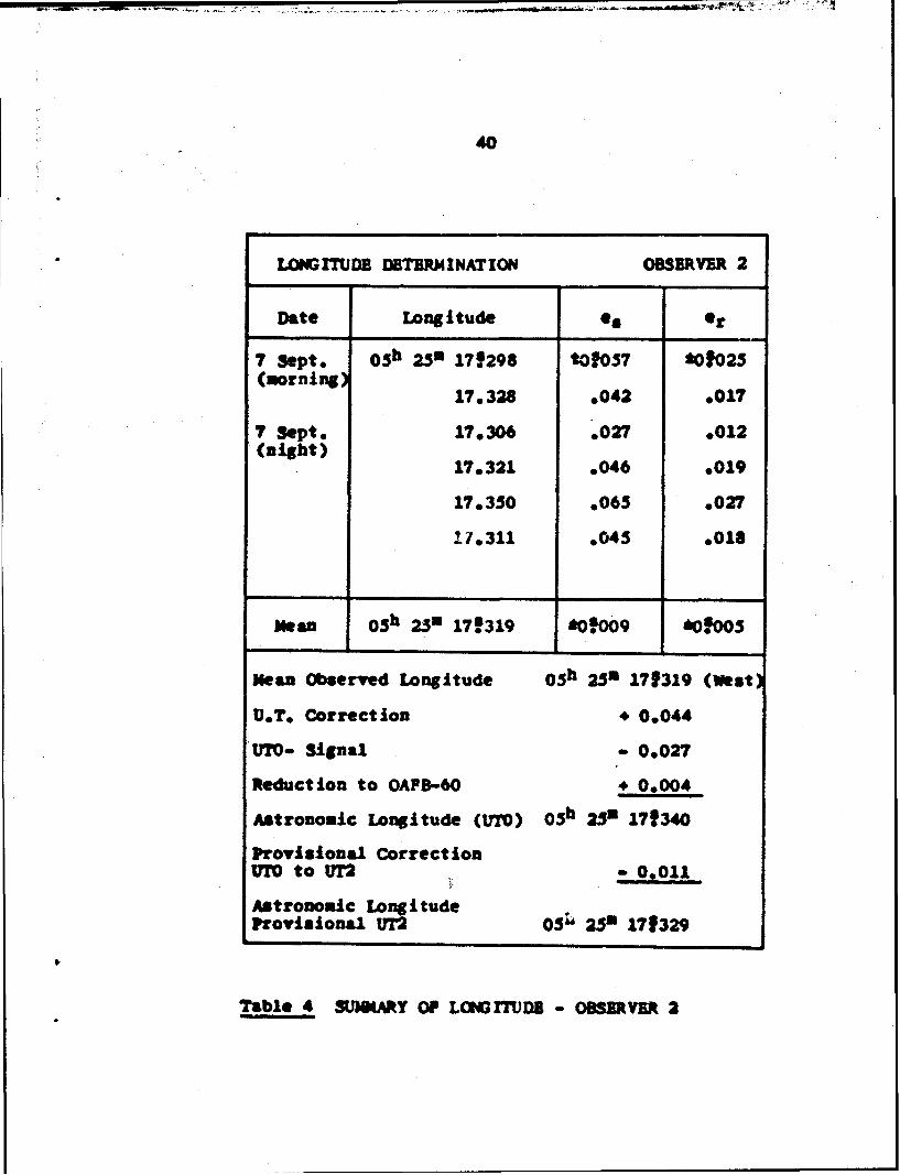
40
LONGIThDB DETERMINATION OBSERVER 2
Date Longitude •s or
7 Sept, 0 5 h 250 17f298 tOf0S7 *01025(morning)
17.328 ,042 9017
7 Sept, 17.306 .027 *012(night)
17.321 .046 .019
17,350 .065 .027
11,311 ,045 I01a
Mean 03h 251 17f319 *o0.009 aoS*00
Mean Observed Longitude 0 5 h 25m 171319 (West)
UDTe Correction 4 0.044
U170.- Signal 0,027
Reduction to OAPB-60 4 0.004
Astronomic Longitude (U70) 0 5 h 25m 171340
Provisional CorrectionV177 to U72 - 0.011
Astronomic LongitudeProvisional UT2 03S 2 5 m 171329
Table 4 SUMARY OF LONICTUDE - OBSERVER 2
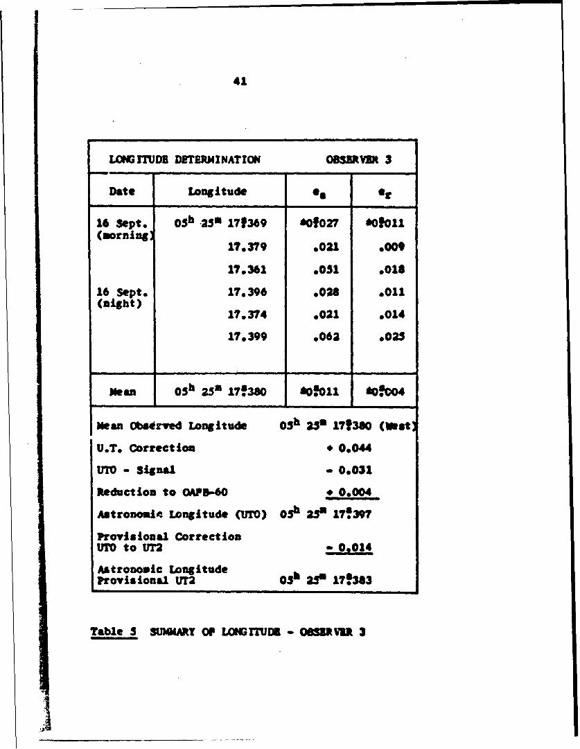
41
L0GI UDS DETERNMINATION GBIRVB 3
Date Longitude e8 et
16 Sept. 0 5 h .25 171369 60027 *01011(morning)
17,379 9021 .000
170361 ,001 .018
16 Sept. 17,396 .028 0011(night) 17.374 .021 e014
17.399 *062 .025
Mea 0 5 h 25" 17.380 ,0o.oll *.0•04
Mean Observed Longitude 0 3h 253 171380 (Weast
U.T. Correction * 0.044
UTO - Signal 0.031
Reduction to OAD-60 * 0,004
Astronomic Longitude (UTO) 03h ;20 17f397
Provisional Correct ionUTO to UT 0,0014
Astronomic LongitudeProvisional UT2 03h 250 17,8383
Table 5 SUMMARY OP 1GITU18D - OCURVIR 3
42
4.8 Analysis of Longitude Results
A total of 10 sets of longitude were rejected after
computation. Maile the number of rejects does seem
exceptionally high the reasons for the rejections are
significant and must be considered before any conclusions
can be made.
Three sets were rejected due to gross misalignment
of the instrument in azimuth, on two or more stars of a
set, of such magnitude that could only result from the
observer misreading the horizontal plate. These rejections
could be directly attributed to observer inexperience
with the instrument. In addition, 2 sets observed by
Observer 2 on the 17th of September, some ten days after his
other observations, agreed closely with each other, but
differed from the mean of all his observations by more
than 0.804. They did agree very closely with observations
made by Observer 3 on the two immediately prior nights.
The marked difference in the observations made by the
same observer might well have been caused by the severe
changes in the weather conditions, particularly a change
in the wind direction, or to changes in the auxiliary
equipment used, or to a combination of such unknown
factors. Similar observations have been recorded using
accepted "first-order" instruments. The remaining re-
jections were due tc residuals in excess of 0.304 or a
combination of high residuals and high probable error
43 a
of the set.
No effort was made to rescale the star transit
times# an operation that can sometimes change the Al
"as determined by a set significantly. When such a condi-
tion ezists it usually is related to observations that
have inconsistant star tracks, which are indicative of
bad visibility or observer inadequacies rather than the
Insttumentation. It seems wiser to simply reject such
work,

CHAPTER 5
PRACTICABILITY OF THE DiM3-A AS A FIELD INSTRUMENT
5.1 Introduction
The design and production of a highly precise field
instrument is as much an art as an engineering feat.
Accuracy, feasibility, durability, rellability, Irorta-
bility, Compactness, weight, observer convenience, cost,
maintainence, and versitility are just a few of the factors
that must be considered. It is not always possible to
find a solution that fulfills all the requirements as
completely as one might desire, and compromises are
inevitable. Indeed, even the most qualified critics may
disagree on the merits and liabilities of the most basic
components of a field instrument.
This chapter contains the favorable and adverse
criticisms and suggestions of the five observers that
used the instrument during this study. They do not
necessarily represent unanimous opinions and I would
expect that other users may disagree with some of the
statements.
5.2 Telescope
As a part of this study, simultaneous observations
were made on the same stars with a [MM3-A and a T-4,
The star images appeared to be slightly smaller, but of
equal or slightly greater intensity in the DI4K3-A.
The instruments superior lighting and focus systems
45
and the elimination of nearly all stray light (observa-
tions of the stars as dim as 7.0 magnitude were made in
a lighted observatory) makes it possible to produce
exceptionally sharp star Images over a wide range of
magnitudes.
5.3 Focusing
Pocusing of both the star Image and the reticule
pattern is quickly, concisely, and conveniently accom-
plished by the focus knob and ocular focusing ring.
It would seem wise to have the focus knob capped to
prevent the possibility of accidental unknown changes in
focus, since even small changes in focus could have
adverse effects on observations such as latitude,
3.4 Astronomic Micrometer
The Nk3-A's astronomic micrometer has many sub-
stantial improvements incorporated into its design.
The optically read "tdrum scale" is especially praise-
worthy. The bold, easily read mnmbers and graduationse
are very evenly illuminated by the tinted rheostatically
controlled internal lighting system - a combination that
not only reduces eyestrain to a mininmm but makes mis-
reading very unlikely. The differences between this
completely optical system and the graduated-kmob system,
such as employed by the T-4, are reminiscent of the
differences in the plate reading systems of the internally
•- 46
lighted optically read theodolite and the double-circle
vernier read engineer's transit.
.Oe seemingly valid adverse criticism of the DIK3-A's
drum-scale Is the use of 120 divisions. Mhile this does
make each graduation very nearly equal to one second
of arc, equatorial value, any minor advantages that might
result from such a condition are more than offset by the
sacrifice of a decimal relationship between the whole
turns as determined by the reticule lines and the fraction-
al turns as read from the drum scale. This adds unnecessari-
ly to the computations and is a possible source of error.
The clamping knob allows the micrometer to be rotat-
ed from the azimuth to zenith distance measuring position,
or back, without changing focus or using any accessory
tools. This Is imot only an observer convenience, but
a time saver as well.
The selection of the approximate equatorial value
is a very important consideration in the design of an
astronomic micrometer. The entire tempo of star obser-
vations and the attainable accuracies of certain deter-
minations are directly effected by the equatorial value
selected.
It is important that during longitude determinations
the observer has sufficient time to properly accomplish
all the necessary readings and reversing operations
between the end of the track-in and the beginning of the
47
track-out of any star. Common practice is for the
observer to pick up the star slightly outside the $ ( 13 )
wire and track the star approximately 21 turns, thus
leaving off at about 2f to 2j turns from transit. Since
he will begin the track-out from that same point be =mst
be able to perform all of the necessary operations and
be ready to begin the track-out in the tine required
for the star to travel about 3$ turns. With the DKN3oA
this is about 45 seconds for equatorial stars.
During the course of this study numerous stars of
very low declinations were observed. With only a mini-
ma of practice the observers were able to meet the time
requirement.
The most important, demanding, and fatigue.'-W duty
of the observer during longitude observations Is the
actual tracking of the stars. It is an advantage then
to reduce the tracking time to a minimum, cossistiat with
the required accuracy, because it t likely that the
observer efficiency and accuracy will diminish as he
tires. The I)M3-A requires 20% less tracking than the
T-4 - a significant reduct! n.
5.M Jorrebow Level Uystem
The Morrebow level system in its present form is
adequate, but sIewhat cumbersome under field €omditLsin.
The actual operating and reading of the levels once they
48
ha Mbeen mounted and adjusted creates no difficulties.
The vials are clearly marked and conveniently read in
the overhead mirror. The internal bubble lighting
system was not used during this study, at the recomen-
dation of the manufacturer, but either the Instruments
hand lamp or an ordinary flashlight provided adequate
lighting.
The differences in instrumental meridian inclina-
tions as determined by the two different vials were
small, in the order of t 0'l0 and showed no correlation
to the degree of Instrument dislevelment. The major
source of the differences is likely due to random read-
Ing inaccuracies.
The Horrebow level mount is not desirable for field
operations. In order to adjust the bubbles' lengths
which requires dumping the vials, the entire mount must
be removed from the instrument. With bubbles of such
high sensitivity it is very difficult to accurately
determine the bubbles' lengths until the entire system
has been remounted and the bubbles have had time to come
to rest. It may sometimes be necessary to repeat the
process several times before both bubbles can be made
the desired length. The process can be time consuming,
produce excessive wearing of the system and create oppor-
tunities for damaging the instrument and levels. The
49
system does have the advantage that the levels cannot
be accidentally dumped during the course of observations,
but this is of little significance to experienced observ-
eras
A more desirable system, that could be achieved
through minor instrument modification, would permit the
easy removal of the levels alone. The MoUnt would then
be sent-permanent in nature (the entire mount would not
normally be removed in the field) and only the levels
would be removed during transporting. The bubbles' lengtbs
would be more easily adjusted, danger of Instrument
damage would be minimized, and the advantage that the
bubbles could not be accidentally dumped vould not be
sacrificed. The entire system would still be relatively
easily removed for maintainence.
5.6 Levelins Knobs
The leveling knobs tend to be slightly stiff to
operate, especially when the heavily weighted striding
level is in place, and make fine leveling a rather
tedious procedure. Consequently, minor wtouch-up"
leveling during an evenings work is not easily accomplish-
ed and if the instrument drifts outside the level toler-
ance the entire leveling procedure must be repeated.
The disadvantage Is minimized by the excellent stability
of the Instrument and the end result is a relatively
depirable system.
50
5.7 Setting Zenith Distances
It was mentioned in Section 1.6 that the 13r13-A
does not have an auxiliary setting circle, such as the
T-4, and therefore the telescope must be set to the
proper zenith distance for star pick-up using the vertical
circle.
Any doubts about the systems adequacy were quickly
dispelled as the observers found that settinp could be
made with an accuracy of about A 1 minute of azc in a
matter of seconds. The exceptinally short telescope can
be manipulated with one hand, leaving the other hand free
to operate the vertical clamp, while viewing the plate
through the reading ocular. A setting circle Is not
only not needed, but would most likely prove a hindrance
to the observer.
5.8 Additional Pactors and Conclusions
There are many small Items that may not seen Im-
portant in themselves, but never the less significantly
effect the 1X3)3-A's value as a field Instrument.
The optical plummet provides a convenient method
for accurately centering the instrument over a mark -
an important requirement for azimuth determinations.
Prism eyepieces are available for use during observations
such as azimuth or triangulation. The lighting system,
completely rheostatically controlled, is excellent
throughout the instrument. The instrument's control knobs
are very conveniently located.
The tool kit that is Included with the Instrument
and located in the base of the carrying base is not
completely adequate. The auto-collimator light housing
tends to Interfer with one of the micrometer tracking
knobs. The deeply recessed alidade level is rather
difficult to view.
These are just a few of the items that add and de-
tract from the DKM3-A. and effect an observer's overall
opinion of the instrument.
The reactions of the five observers that used the
[NM3-A during this study could only be described an
enthusiastic. The instrument shows every sign of being
an excellent field instrum~ent.
IHAPTSR 6
CONcLUS IONS
6.1 Accuracy
The results of the limited number of observations
made during this study indicate that the DKM3-A is capable
of producing both first-order latitude and first-order
longitude determinations as defined in Chapter 3 of this
thesis.
The Instrument's latitude capabilit!ies have further
been confirmed by an Informal test condur'ted by the
USC & GS in May of 1964 ( 18 ). The Geodetic Survey of
Canada is presently making an extensive field test of the
MM3-A invclving observations on 27 field stations. The
results of that test should produce more reliable con-
clusions about its attainable accuracies t 6 ).
6.2 Field C0, aracteristics
The MX3-A is an excellent field instriment from
the viewpoints of portability, versatility, and observer
convenience. While very little can be concl;ided about
an instruments durability, required maintainance, dependa-
b~lity, and such related long term considerations fLM
a test of such short duration, the *M-3 has already
proven that the basic mechanicil and optical components
are sound, and it Is likely that the IXN3-4 will prove
adequate in these respects also. Th4 additions of the
52I
'3
astronomic micrometer, weighted striding level, ond
double Horrebew level do add considerably to the weJght
that the vertical axis system must support, and its
effect on the life of the system could prove significani
A field Instrument can only prove itself after years of,
use under varying conditions, but the DKOA-A appears to
have all the neces3ary ingredients to ms!e it a valuable
addition to the geodesists' array of tools.
_ _ _
BIBLIOGRAPHY
( I ) Bamford, A. 3. peort of the Columbia observatoryVV271-
t4 b Somford, G. Geodesy second edition, OxfordUniversity Press, London, England(1962)
( 3 ) Boss, 3. 1eneral Catalogue of 33342 Starsfor the Epoch M90, Carnegie7nstitute, Washington D.C.
( 4 ) Connor, V. L. Second Order Astronomic PositionDetermination, A Thesis Presentedin Partial Fulfillment of theRequirements for the Degree Master.of Science, Ohio State University,Columbus, Ohio, (1964)
( 5 ) Poandelli, M. Examination of the Precision of theKern DIM3 Theodolite, Research1Department, the Military GeographicInstitute, Plorence, Italy
( 6 ) Gregerson, L.P. Letter to Author, December 21,1964,Department of Mines and TechnicalSurveys (Geodetic Survey of Canada)Ottawa, Canada
( 7 ) Hoskinson, A. 3. Manual of Geodetic Astronomy, U.S.and Coast and Geodetic Survey STpecial
Dtierksen, J. A. Publication No. 237, U.S. GovernmentPrinting Office, Washington D.C.(1952)
( S ) International Astronomic Union parent Places ofPundamental Stars, i-4 -"AstronomNsches Rechen Institute,Heidleberg, Germany, (1964)
( 9 ) Kern & Co. Ltd. Instruction Manual Kern DWM3 PirstOrder Tkeodol te, Aarauga Switzerlaid
(10) Zern & Co. Ltd. Instruction Manual AstronomicalDouble Circle Theodolite -. •3 .1-
Fr iu, gitzerland
54
BIBLIOG1 APHY
( 11 ) Kneissi, M. "Examination of the Horizontal Circleof the Kern DKM3", Bulletin 6, Kern&Co. Ltd., Aarau- Switzerl-nd
( 12 ) Lamping, N. E. An Investigation of the PersonalError in the Longitude Micrometerof the Astronomical Theodolite, AThesis Presented In Partil Fui-fillment of the Requirements forthe Degree Master of Science, OhioState University, Columbus, Ohio(1964)
( 13 ) Nautical Almanac Office of the U. S. Naval Obser-vatory The .American Ephemeris andNautical Almanac for the Year 1964U. S. Government Printing Office,Washington, D. C.
C 14 ) Odermatt, H. Instructions for the Determinationof Geographic Position, Henry WildSurvey Instrument Supply Company,Ltd. Heerbrugg, Switzerland
( 15 ) Passauer, J.L. An Investigation oi Combined Methodsof Second Order Astronomic PositionDeterminations A Thesis Presented"in Partial Fulfillment of theRequirements for the Degree Masterof Science, Ohio State University,Columbus, Ohio (1964)
C 16 ) Smart, W. M. Textbook on Spherical AstronomyThe University Press, Cambridge,England (1962)
( 17 ) Sukman, L. 1. The Effect of the InstrumentalCon.tants on the Determinatioz ofAstronomic Positions, A ThesisPresented in Partial Fulfillment ofthe Requirements for the DegreeMaster of Science, Ohio StateUniversity, Columbus, Ohio (1962)
55
BIDLIOGRAPHYO
( 18 ) Thorson, C. W. Letter to Author, August 13, 1964U.S. Coast and Geodetic SurveyWashington, D.C.
C 19 ) U.S. Naval Observatory Tine Service Notice No. 921 December 1960, Washington D.C.
( 20 ) U.S. Naval Observatory Time Service Notice No. 4210 January 1962, Washington D.C.
( 21 ) U.S. Naval Observatory Time Service Weekly Notices180, 181, 182, 13 and' 184 for themonth of.September 1964
( 22 ) Wehrll, H.J. Letter to Author, October 2, 1964Kern Instrument Inc. , Port Chester,New York
( 23 ) 1381st Geodetic Survey SquadronObservation and Computation Instruc-tions for Astronomic PositionDeterninations, Orlando APB, OrlandogFlorida
56
Ix . - eum m . . I • I il • I. . • I