Closed Loop Control of Excitation Parameters for High...
12
International Journal on Electrical Engineering and Informatics - Volume 2, Number 3, 2010 232 Closed Loop Control of Excitation Parameters for High Speed Switched Reluctance Generator Using MATLAB/SIMULINK S. Suthapadmanabhan 1 and K. Kannan 2 1 Department of Electrical and Electronics Engineering, Anna University, Panrutti Campus, Tamil Nadu, India 2 Department of Electrical and Electronics Engineering, R.V.S College of Engineering and Technology, Dindigul, Tamil Nadu, India. [email protected], [email protected] and Abstract: This paper presented a novel Proportional Integrator Current Chopping Control (PI-CCC) based on Switched Reluctance Generator (SRG).The fundamental principle of the PI-CCC is based on the minimization of torque ripple of the SRG. The excitation parameters for the SRG system operates at sufficiently high speed that it operates in the single pulse mode. In this paper PI-CCC based SRG modeled are simulated by using MATLAB/SIMULINK. In this model to analyze both dynamic and steady state system output its respectively, the power converter, excitation source, and loads were simulated based on SIMULINK/Sim power systems (PSB). Index Terms: Proportional Integrator Current Chopping Control (PI-CCC), Switched Reluctance Generator (SRG) 1. Introduction The applications of Switched Reluctance Generator (SRG) under special environments have being increased day by day, because they have several inherent advantageous features such as rug, low cost, robustness and possible operation in high temperatures or harsh environments. These features make the SRG a candidate for applications such as aircraft engine starter/generator [1], automotive starter/generator[2], and wind turbine generators[3]. Unfortunately, SRG is a multivariable, strong-coupling and non linear system, it is very difficult to model and analyze. To analyze the operating performance of SRG, lots of modeling methods were presented. The circuit simulation program “SPICE”, it has certain limitations[4]. Reference[5] uses object oriented program technique, it is very flexible, but it is difficult to actualize, because it needs the complete mathematical model of the system. The introduce some modules and M-file in MATLAB to build the nonlinear mathematical model of the magnetization curves, it is accurate, but the simulation speed is slow[6]. A novel method for nonlinear modeling based on circuit simulation are built by self- defining M-functions and basic modules SIMULINK/simulink library. The model built in this paper is very flexible and visual; its simulation speed is very fast[7]. but, The turn on and turn off angles are fixed. Control of the SRM is more complicated for generator operation than it is for motor operation. Operating as generator, the turn-on and turn-off angles control the peak phase currently jointly and severally. The control of the excitation parameters for the switched reluctance generator (SRG), where the SRG system operates at sufficiently high speed, that its operates in the single pulse mode. [8]. This paper presents a novel modeling for Nonlinear Modeling and closed loop control of Excitation parameters for high speed switched reluctance generator (SRG). In this simulation model, the power inverter, excitation source, inductor model, design of each phase model, and loads are simulated only SIMULINK/Simpower system. The turn-on and turn-off angles are the two parameters through which we can control the simulation results really report the work status of the generator system and validate the applicability of the model and the proposed controller. The proposed control system is designed turn off angle is optimum for a given speed
Transcript of Closed Loop Control of Excitation Parameters for High...

International Journal on Electrical Engineering and Informatics - Volume 2, Number 3, 2010
232
Closed Loop Control of Excitation Parameters for High Speed Switched Reluctance Generator Using MATLAB/SIMULINK
S. Suthapadmanabhan1 and K. Kannan 2
1Department of Electrical and Electronics Engineering, Anna University,
Panrutti Campus, Tamil Nadu, India 2Department of Electrical and Electronics Engineering, R.V.S College of Engineering and
Technology, Dindigul, Tamil Nadu, India. [email protected], [email protected] and
Abstract: This paper presented a novel Proportional Integrator Current Chopping Control (PI-CCC) based on Switched Reluctance Generator (SRG).The fundamental principle of the PI-CCC is based on the minimization of torque ripple of the SRG. The excitation parameters for the SRG system operates at sufficiently high speed that it operates in the single pulse mode. In this paper PI-CCC based SRG modeled are simulated by using MATLAB/SIMULINK. In this model to analyze both dynamic and steady state system output its respectively, the power converter, excitation source, and loads were simulated based on SIMULINK/Sim power systems (PSB). Index Terms: Proportional Integrator Current Chopping Control (PI-CCC), Switched Reluctance Generator (SRG) 1. Introduction The applications of Switched Reluctance Generator (SRG) under special environments have being increased day by day, because they have several inherent advantageous features such as rug, low cost, robustness and possible operation in high temperatures or harsh environments. These features make the SRG a candidate for applications such as aircraft engine starter/generator [1], automotive starter/generator[2], and wind turbine generators[3]. Unfortunately, SRG is a multivariable, strong-coupling and non linear system, it is very difficult to model and analyze. To analyze the operating performance of SRG, lots of modeling methods were presented. The circuit simulation program “SPICE”, it has certain limitations[4]. Reference[5] uses object oriented program technique, it is very flexible, but it is difficult to actualize, because it needs the complete mathematical model of the system. The introduce some modules and M-file in MATLAB to build the nonlinear mathematical model of the magnetization curves, it is accurate, but the simulation speed is slow[6]. A novel method for nonlinear modeling based on circuit simulation are built by self-defining M-functions and basic modules SIMULINK/simulink library. The model built in this paper is very flexible and visual; its simulation speed is very fast[7]. but, The turn on and turn off angles are fixed. Control of the SRM is more complicated for generator operation than it is for motor operation. Operating as generator, the turn-on and turn-off angles control the peak phase currently jointly and severally. The control of the excitation parameters for the switched reluctance generator (SRG), where the SRG system operates at sufficiently high speed, that its operates in the single pulse mode. [8]. This paper presents a novel modeling for Nonlinear Modeling and closed loop control of Excitation parameters for high speed switched reluctance generator (SRG). In this simulation model, the power inverter, excitation source, inductor model, design of each phase model, and loads are simulated only SIMULINK/Simpower system. The turn-on and turn-off angles are the two parameters through which we can control the simulation results really report the work status of the generator system and validate the applicability of the model and the proposed controller. The proposed control system is designed turn off angle is optimum for a given speed
My Computer
Text Box
Received: April 29, 2010. Accepted: August 13, 2010
My Computer
Line
233
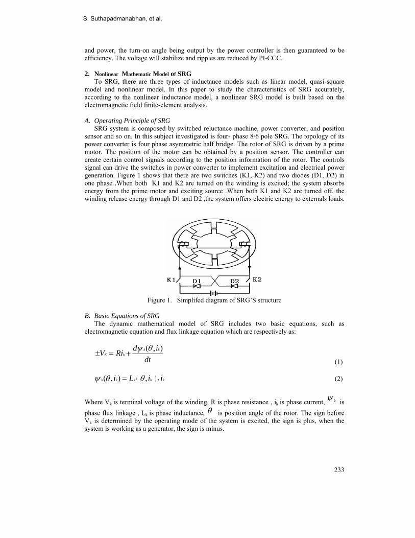
and power, the turn-on angle being output by the power controller is then guaranteed to be efficiency. The voltage will stabilize and ripples are reduced by PI-CCC. 2. Nonlinear Mathematic Model of SRG To SRG, there are three types of inductance models such as linear model, quasi-square model and nonlinear model. In this paper to study the characteristics of SRG accurately, according to the nonlinear inductance model, a nonlinear SRG model is built based on the electromagnetic field finite-element analysis. A. Operating Principle of SRG SRG system is composed by switched reluctance machine, power converter, and position sensor and so on. In this subject investigated is four- phase 8/6 pole SRG. The topology of its power converter is four phase asymmetric half bridge. The rotor of SRG is driven by a prime motor. The position of the motor can be obtained by a position sensor. The controller can create certain control signals according to the position information of the rotor. The controls signal can drive the switches in power converter to implement excitation and electrical power generation. Figure 1 shows that there are two switches (K1, K2) and two diodes (D1, D2) in one phase .When both K1 and K2 are turned on the winding is excited; the system absorbs energy from the prime motor and exciting source .When both K1 and K2 are turned off, the winding release energy through D1 and D2 ,the system offers electric energy to externals loads.
Figure 1. Simplifed diagram of SRG’S structure
B. Basic Equations of SRG The dynamic mathematical model of SRG includes two basic equations, such as electromagnetic equation and flux linkage equation which are respectively as:
( , )k kK k
d iV Ridt
ψ θ± = +
(1) ( )( , ) ,k k k k ki L i iψ θ θ •= (2)
Where Vk is terminal voltage of the winding, R is phase resistance , ik is phase current, kψ is phase flux linkage , Lk is phase inductance, θ is position angle of the rotor. The sign before Vk is determined by the operating mode of the system is excited, the sign is plus, when the system is working as a generator, the sign is minus.
S. Suthapadmanabhan, et al.

234
3. SRG Power Converter The most commonly used Switched Reluctance Generator is the classical half-bridge converter which has two power switches and two diodes per phase as shown in Figure 2 while the lower switch is in charge of commutation, the upper one is used to perform PWM switching control, The main advantage of this converter is that each phase can be controlled independently.
Figure 2. SRG Power Converter
A. Excitation Mode
Figure 3(a). Excitation mode
Figure 3(b). Freewheeling mode
During this mode, Q1 and Q2 are ON to yield the equivalent circuit. B. Free Wheeling Current-Boosting Mode Initially, the voltage drops of RS and L can lead to the decrease in winding current. The current is continuously built up by the negative value of back EMF. During higher speed and higher DC-link voltage, the duration of this mode will be increased. C. Generating Mode During the generating mode, both of the two switches are turned off with the circuit and current path being show in Figure (4). This action will impose the negative DC -link voltage upon the active stator phase, At this time, the mechanical energy from prime mover is converted to electrical energy. The phase winding voltage equation in this mode can be written us:
Closed Loop Control of Excitation Parameters

235
*( ) , 0o S
diV R L e edt
− = + + < (3)
Figure 4. Generating mode 4. Nonlinear Simulation Model of SRG In order to simplify the simulation process, in this paper four assumptions are introduced as follows: ∗ Parameters of each phase in SRG are symmetrical. ∗ Ignore mutual inductance and leak inductance. ∗ Ignore hysteric’s and eddy effect. ∗ Switches in power converter are ideal device and the exciting source is constant.
Figure 5. Simplified diagram of SRM’s structure A. Nonlinear Model of Inductance
Figure 5 shows In order to analyze the SRG by MAGNET, the geometrical model of the machine should be plotted at first and appropriate materials are assigned to different regions. Figure 6 and Figure 7 are as shown the align and unaligned position of the SRG. According to the a nonlinear SRG model is built based on the electromagnetic field finite-element analysis.
S. Suthapadmanabhan, et al.

236
Figure 6. Distribution of flux lines in the aligned position.
Figure 7. Distribution of flux lines in the unaligned position
To simulate the dynamic performance accurately, the relational expression of inductance position angular of rotor and phase current must be described exactly. The magnetic circuit of the SRM is saturated and non-linear. The harmonic component of the inductance can be expressed.
0 1( , ) ( ) ( ) (cos( ) )rKL i L i L i Nθ θ π= + ∗ + (4)
max min( ) ( )( )2
OL i L iL i +
= (5)
max min
1( ) ( )( )
2L i L iL i −
= (6)
Where Lmax(i) is aligned position inductance, Lmin(i) is the unaligned position inductance. Lmax, Lmin can be obtained by experiments and electromagnetic field finite-analysis(FEA). Lmax(i) can be expressed as a polynomial function with respect to the phase current(i) which can be obtained by curve fitting Figure 8.
Closed Loop Control of Excitation Parameters

237
Figure 8. Relationship between inductance,. turn angle of rotor and phase current.
max2 3 4( ) 0.136 0.0045 0.0056 0.0022 0.00035L i i i i i= − + − + (7)
B. Model of Each Phase
Figure 9. The simulation model of Phase A
Motor Windings presents the model of windings, it is built according to (1)-(7). The parameters of each phase are symmetrical, take phase A example, its simulation model shows the detailed structure of the nonlinear machine modeling is created by Embedded Block in Figure 9. In Figure. 10 shows the Inductance Calculator creates the inductance of the winding through self –defining Embedded Simulink to (4)-(7).
S. Suthapadmanabhan, et al.

238
Figure 10. Inductance Calculator Signal to Source and Source to Signal are connecting elements between simulink modules and PSB modules.Signal to Source is a controlled current source, it converts current signal to a current source. C. Design of Controller The control objective of controller is creating high performance control commands to maintain the output voltage of the system. The performance controller seriously affects the dynamic and static characteristics of the system. To SRG, there are lots of controllable
parameters. turn-off angle offθ ,turn on angle onθ ,turn-off peak current Ic and so on. Accordingly, there are three typical control strategies. Angle position Control (APC), Current Chopping Control(CCC) and Pulse Width Modulation(PWM). The optimum turn-off angles can be represented as
1 2 3 4off k p k k p kθ ω ω= + + + (8)
ON OFF CONDθ θ θ= − (9)
( , )O on offV fcn θ θ=
(10) The performance of the system is very sensitive to the turn-off angle, the implement of APC has certain difficulties. In this paper, a high-performance control strategies named PI-CCC control (PCC) is proposed. The new controller has two closed-loops: outer voltage closed-loop (VC) and inner current-. Loop(CC).It obtains the D-value between the output voltage of the system and the Given signal(270) firstly, and then creates the reference current Iref through PI controller. CC is based on current chopping control, it is implemented by the Relay module in SIMULINK/Simulink library. The turn-on, turn-off and reference current are three parameters through which we can control the electric power generation.it can be seen that the optimal-efficency turn off angles can be characterized as a function of power and speed level.within the closed-loop power controller,the optimal efficency turn-off angle is deterrmined from an analytic curve fit.The turn-on angle is then used as the degree of freedom necessary to regulate the power produced by the SRG.Table. 1 provides the parameters used in the voltage and power controllers.
Closed Loop Control of Excitation Parameters

239
Table 1. The Parameters for the Controllers Control of the SRM is more complicated for generation operation than it is for motor operation.Operrating as a motor , the turn-on angle can be directly used to directly control the peak phase current,thereby partitioning the responsibilities of the turn-on angle and Conduction angle.Operating as generator,the turn-on and turn-off angles control the peak phase current jointy and discussed. D. Exciting Circuit and Loads Figure 11 shows the PSB model of exciting source and loads. Two Capacitor (C1,C2) Parallel an inductance (L) is series connected to the output ports of the power inverter, they compose a filter of sytem’s output. DC is direct current exciting source, it supplies the original exciting current to the windings. The Diode module over DC is used to prevent the current of SRG from returning to DC. The switching device over load it use to imitate sudden load-on and load-off , it is composed f an IGBT module and a step-function signal module.
Figure 11. PSB simulation model of exciting source and loads
In order to verify the feasibility proposed model of a Four phase 8/6 SRG system is built and simulated in Figure 12. According to the output voltage of the system and given voltage, Controller creates reference current to the current loop of each phase to implement double
Quantity Value Units KP(Power) 0.033 °/W(electrical) Ki(Power) 1.899 °/Jelectrical) Θcond 178 °(electrical)
K1 7.41e-7 °sW(electrical)
K2 5.55e-4 °s(electrical)
K3 4.44e-3 °/W(electrical)
K4 31.33 °(electrical)
KP(Voltage) 140.65 W/V
Ki(Voltage) 1620.80 W/Vs C 1600e-6 Farad
S. Suthapadmanabhan, et al.
240
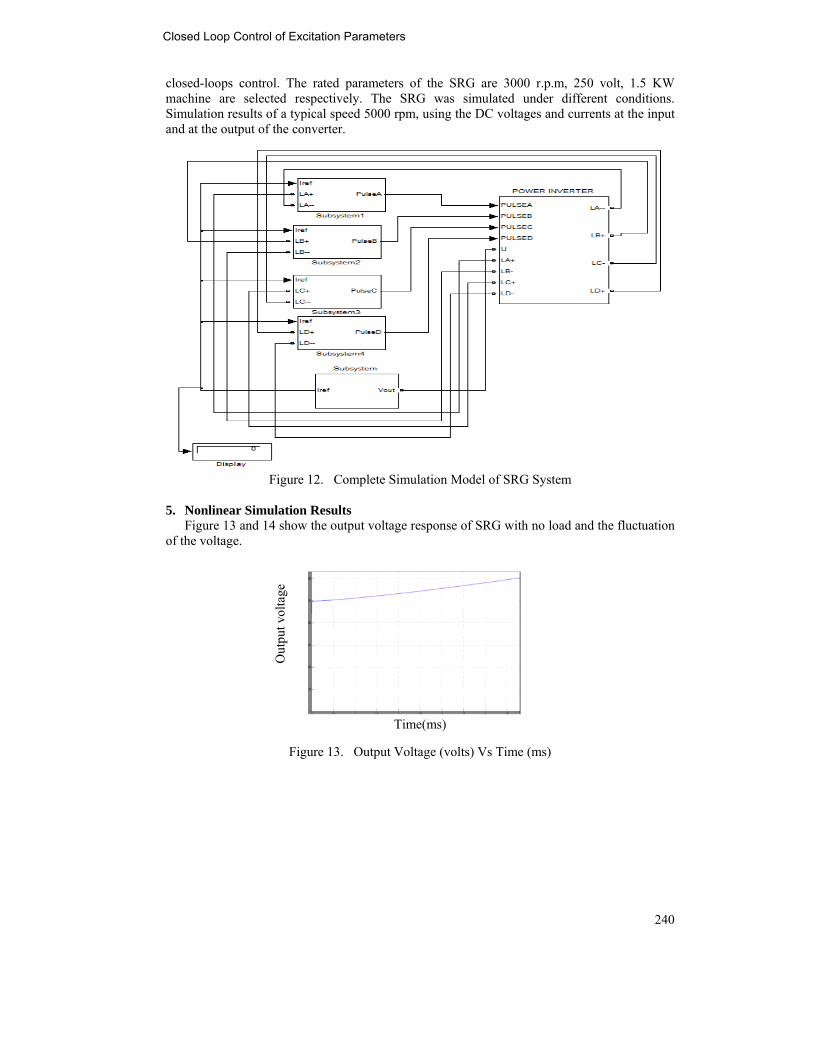
closed-loops control. The rated parameters of the SRG are 3000 r.p.m, 250 volt, 1.5 KW machine are selected respectively. The SRG was simulated under different conditions. Simulation results of a typical speed 5000 rpm, using the DC voltages and currents at the input and at the output of the converter.
Figure 12. Complete Simulation Model of SRG System
5. Nonlinear Simulation Results Figure 13 and 14 show the output voltage response of SRG with no load and the fluctuation of the voltage.
Time(ms)
Figure 13. Output Voltage (volts) Vs Time (ms)
Out
put v
olta
ge
Closed Loop Control of Excitation Parameters

241
Time
Figure 14. Output Voltage (volts) Vs Time (ms) Capacitor (across)
The voltage will stabilize at 304 V after 0.01 second. The ripples of the voltage very small. To test the dynamic regulation performance, suddenly add load at 0.005 sec. The output voltage can stabilized at 304V after a short regulating process of the output voltage.
Figure 15. Inductance (Henry) Vs Time(ms) Figure 15 and 16 are shown the represent of inductance and phase current in the wave form circuit. This output circuit reduce the torque ripple.
Figure 16. Phase Current (Amps) Vs Time(ms)
Out
put v
olta
ge
S. Suthapadmanabhan, et al.

242
Table 2 is discussed in different types of load and speed are changed but, output voltage is maintain the constant voltage is produced. The overall system and control is simulated with the SRG model based on MATLAB/SIMULINK. The results of these tests show that the new control simulink model provides an efficient SRG controller that is easy to implement.
Table 2. Simulation Result of Comparison the different Loads VS
volts SPEED r.p.m
C Farad
RL ohms
VO Volts
250 3000 25 100 298
250 3500 25 44 300
250 4000 25 22 300
250 5000 25 11 304
Conclusion This paper proposed a PICCC based Switched Reluctance Generator. A model of SRG has built using MATLAB/SIMULINK Software. This proposed SRG is minimize the ripple and constant steady state output voltage are stabilized. The simulation results really report the work status of the generator system and validate the applicability of the model and proposed controller. The model proposed by this paper can be used to analyze the affections of different load status and work environments to the dynamic and static performance of SRG system. APPENDIX Values of parameters used in modeling and simulation. R=25Ω, Nr=6, Lmin=0.01H, Vexciting=250v, RL=100Ω, θoriginal=10°, Kp=10, Ki=5. Acknowledgement I am grateful to Dr.S.Sutha Assistant Professor Anna University (Panrutti campus) in Trichy and Mr. R. Karthikeyan Assistant Professor, SVCE in Chennai Department of Electrical and Electronics Engineering for his valuable guidance and encouragement during this project. I would like to thank our entire Department faculty for their valuable suggestions and timely help during this project work. References [1] M. E. Elbuluk and M. D. Kankan, “Potential starter/generator technologies for future
aerospace applications,” IEEE Magazine on Aerospace and Electronic Systems, vol. 12 no. 5, 1997, pp. 24-31.
[2] C. A. Ferreira, S. R. Jones, W. S. Heglund and W. D. Jones “Detailed Design of a 30-KW Switched Reluctance Starter/Generator system for a Gas Turbine Engine Applications,” IEEE Trans, Ind. Applicat, vol 31, no. 3, May/June 1995, pp. 553-561.
[3] Hao Chen, Chao Mang and Xucheng Zhao, “Research on the Switched Reluctance Wind Generator System,” IEEE International Conference on Systems, MAN and Cyber entices, vol. 3, 7-10 Oct, 2001, PP. 1936-1941.
[4] Osamu Inhinokura, Tsukasa kikuchi, kanji nakammurg Tadaki Uatannable and Hai-jiau Guo,”Dynamic Simulation Model of Switched Reluctance Generator” IEEE Transactions vol. 39, no. 5, sep. 2003, pp. 3253-3255.
[5] M. K. EI-Nemr, M. A. Al-khazendar, E. M. Rashad and M. A. Hassanin “Modelling and steady state Analysis of Stand – Alone Switched Reluctance Generator “, IEEE Power Engineering Society General Meeting July 2003, pp. 1894-1899.
Closed Loop Control of Excitation Parameters

243
[6] F. Sores and P. J. Costa Branco,” Simulation of a 6/4 Switched Reluctance Model Based on MATLAB/Simulink Enviorment,” IEEE Transactions Aerospace and Electronics system, vol. 37, July 2005, pp. 989-1009.
[7] Shoujun Son, Weiguo Liu, “A Novel Method and Dynamic Simulation of a Four-Phase Switched Reluctance Generator System Based on MATLAB/SIMULINK”, IEEE 2007.
[8] Yilmaz sozer, David A.Torrey, “Closed loop control of Excitation for High speed Switched Reluctance Generator”, IEEE Trans. in 2003.
S. Suthapadmanabhan received from Government College of Engg Tirunelveli, Manonmaniam Sundarar University in 1996, M.E. from College of Engg Guindy, Anna University Chennai in 2000 and Ph.D. from Anna University Chennai in 2008. Presently, she is working as Assistant Professor of ANNA UNIVERSITY (Panruttui Campus) Tamil Nadu, India.
K. Kannan, received B.E course from R.V.S College of Engineering and Technology in 2006, M.E[PED] from Sri Venkateshwara College of Engineering Sriperumbhdur in 2009. Now, Research Scholar of Anna University Tiruchirappali and present working in Department of Electrical and Electronics Engineering, R.V.S College of Engineering and Technology, Dindigul, Tamil Nadu, India.
S. Suthapadmanabhan, et al.