AMI - dewa.gov.ae
1
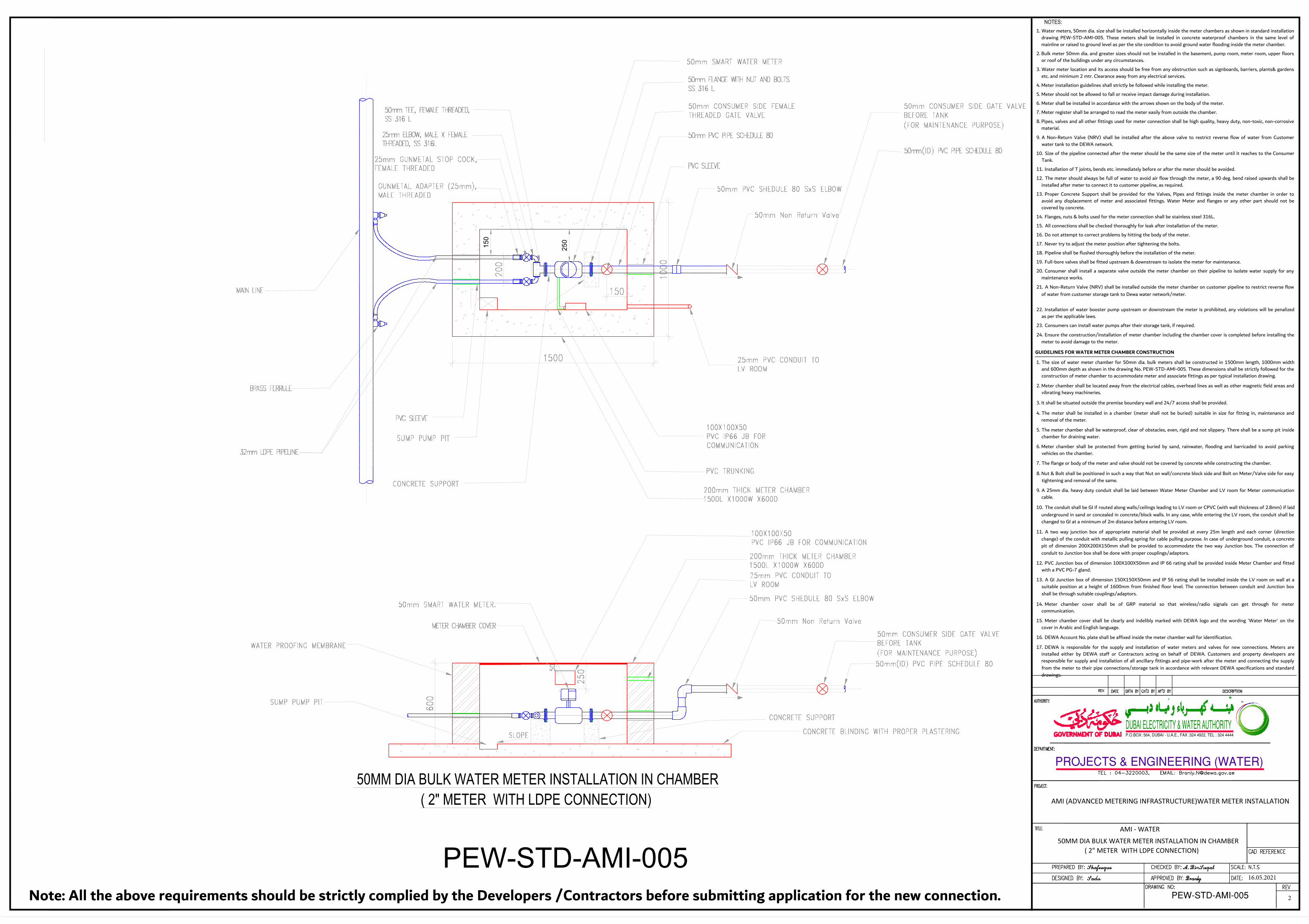
AMI - WATER 50MM DIA BULK WATER METER INSTALLATION IN CHAMBER ( 2" METER WITH LDPE CONNECTION) PROJECTS & ENGINEERING (WATER) DUBAI ELECTRICITY & WATER AUTHORITY P.O.BOX: 564, DUBAI - U.A.E., FAX :324 4922, TEL : 324 4444 AMI (ADVANCED METERING INFRASTRUCTURE)WATER METER INSTALLATION NOTES: 1. Water meters, 50mm dia. size shall be installed horizontally inside the meter chambers as shown in standard installation drawing PEW-STD-AMI-005. These meters shall be installed in concrete waterproof chambers in the same level of mainline or raised to ground level as per the site condition to avoid ground water flooding inside the meter chamber. 2. Bulk meter 50mm dia. and greater sizes should not be installed in the basement, pump room, meter room, upper floors or roof of the buildings under any circumstances. 3. Water meter location and its access should be free from any obstruction such as signboards, barriers, plants& gardens etc. and minimum 2 mtr. Clearance away from any electrical services. 4. Meter installation guidelines shall strictly be followed while installing the meter. 5. Meter should not be allowed to fall or receive impact damage during installation. 6. Meter shall be installed in accordance with the arrows shown on the body of the meter. 7. Meter register shall be arranged to read the meter easily from outside the chamber. 8. Pipes, valves and all other fittings used for meter connection shall be high quality, heavy duty, non-toxic, non-corrosive material. 9. A Non-Return Valve (NRV) shall be installed after the above valve to restrict reverse flow of water from Customer water tank to the DEWA network. 10. Size of the pipeline connected after the meter should be the same size of the meter until it reaches to the Consumer Tank. 11. Installation of T joints, bends etc. immediately before or after the meter should be avoided. 12. The meter should always be full of water to avoid air flow through the meter, a 90 deg. bend raised upwards shall be installed after meter to connect it to customer pipeline, as required. 13. Proper Concrete Support shall be provided for the Valves, Pipes and fittings inside the meter chamber in order to avoid any displacement of meter and associated fittings. Water Meter and flanges or any other part should not be covered by concrete. 14. Flanges, nuts & bolts used for the meter connection shall be stainless steel 316L. 15. All connections shall be checked thoroughly for leak after installation of the meter. 16. Do not attempt to correct problems by hitting the body of the meter. 17. Never try to adjust the meter position after tightening the bolts. 18. Pipeline shall be flushed thoroughly before the installation of the meter. 19. Full-bore valves shall be fitted upstream & downstream to isolate the meter for maintenance. 20. Consumer shall install a separate valve outside the meter chamber on their pipeline to isolate water supply for any maintenance works. 21. A Non-Return Valve (NRV) shall be installed outside the meter chamber on customer pipeline to restrict reverse flow of water from customer storage tank to Dewa water network/meter. 22. Installation of water booster pump upstream or downstream the meter is prohibited, any violations will be penalized as per the applicable laws. 23. Consumers can install water pumps after their storage tank, if required. 24. Ensure the construction/installation of meter chamber including the chamber cover is completed before installing the meter to avoid damage to the meter. GUIDELINES FOR WATER METER CHAMBER CONSTRUCTION 1. The size of water meter chamber for 50mm dia. bulk meters shall be constructed in 1500mm length, 1000mm width and 600mm depth as shown in the drawing No. PEW-STD-AMI-005. These dimensions shall be strictly followed for the construction of meter chamber to accommodate meter and associate fittings as per typical installation drawing. 2. Meter chamber shall be located away from the electrical cables, overhead lines as well as other magnetic field areas and vibrating heavy machineries. 3. It shall be situated outside the premise boundary wall and 24/7 access shall be provided. 4. The meter shall be installed in a chamber (meter shall not be buried) suitable in size for fitting in, maintenance and removal of the meter. 5. The meter chamber shall be waterproof, clear of obstacles, even, rigid and not slippery. There shall be a sump pit inside chamber for draining water. 6. Meter chamber shall be protected from getting buried by sand, rainwater, flooding and barricaded to avoid parking vehicles on the chamber. 7. The flange or body of the meter and valve should not be covered by concrete while constructing the chamber. 8. Nut & Bolt shall be positioned in such a way that Nut on wall/concrete block side and Bolt on Meter/Valve side for easy tightening and removal of the same. 9. A 25mm dia. heavy duty conduit shall be laid between Water Meter Chamber and LV room for Meter communication cable. 10. The conduit shall be GI if routed along walls/ceilings leading to LV room or CPVC (with wall thickness of 2.8mm) if laid underground in sand or concealed in concrete/block walls. In any case, while entering the LV room, the conduit shall be changed to GI at a minimum of 2m distance before entering LV room. 11. A two way junction box of appropriate material shall be provided at every 25m length and each corner (direction change) of the conduit with metallic pulling spring for cable pulling purpose. In case of underground conduit, a concrete pit of dimension 200X200X150mm shall be provided to accommodate the two way Junction box. The connection of conduit to Junction box shall be done with proper couplings/adaptors. 12. PVC Junction box of dimension 100X100X50mm and IP 66 rating shall be provided inside Meter Chamber and fitted with a PVC PG-7 gland. 13. A GI Junction box of dimension 150X150X50mm and IP 56 rating shall be installed inside the LV room on wall at a suitable position at a height of 1600mm from finished floor level. The connection between conduit and Junction box shall be through suitable couplings/adaptors. 14. Meter chamber cover shall be of GRP material so that wireless/radio signals can get through for meter communication. 15. Meter chamber cover shall be clearly and indelibly marked with DEWA logo and the wording 'Water Meter' on the cover in Arabic and English language. 16. DEWA Account No. plate shall be affixed inside the meter chamber wall for identification. 17. DEWA is responsible for the supply and installation of water meters and valves for new connections. Meters are installed either by DEWA staff or Contractors acting on behalf of DEWA. Customers and property developers are responsible for supply and installation of all ancillary fittings and pipe-work after the meter and connecting the supply from the meter to their pipe connections/storage tank in accordance with relevant DEWA specifications and standard drawings. PEW-STD-AMI-005 PEW-STD-AMI-005 50MM DIA BULK WATER METER INSTALLATION IN CHAMBER ( 2" METER WITH LDPE CONNECTION) 250 150 Note: All the above requirements should be strictly complied by the Developers /Contractors before submitting application for the new connection. 16.05.2021 2
Transcript of AMI - dewa.gov.ae
AMI - WATER
50MM DIA BULK WATER METER INSTALLATION IN CHAMBER ( 2" METER WITH LDPE CONNECTION)
PROJECTS & ENGINEERING (WATER)
DUBAI ELECTRICITY & WATER AUTHORITYP.O.BOX: 564, DUBAI - U.A.E., FAX :324 4922, TEL : 324 4444
AMI (ADVANCED METERING INFRASTRUCTURE)WATER METER INSTALLATION
NOTES:1. Water meters, 50mm dia. size shall be installed horizontally inside the meter chambers as shown in standard installation
drawing PEW-STD-AMI-005. These meters shall be installed in concrete waterproof chambers in the same level of
mainline or raised to ground level as per the site condition to avoid ground water flooding inside the meter chamber.
2. Bulk meter 50mm dia. and greater sizes should not be installed in the basement, pump room, meter room, upper floors
or roof of the buildings under any circumstances.
3. Water meter location and its access should be free from any obstruction such as signboards, barriers, plants& gardens
etc. and minimum 2 mtr. Clearance away from any electrical services.
4. Meter installation guidelines shall strictly be followed while installing the meter.
5. Meter should not be allowed to fall or receive impact damage during installation.
6. Meter shall be installed in accordance with the arrows shown on the body of the meter.
7. Meter register shall be arranged to read the meter easily from outside the chamber.
8. Pipes, valves and all other fittings used for meter connection shall be high quality, heavy duty, non-toxic, non-corrosive
material.
9. A Non-Return Valve (NRV) shall be installed after the above valve to restrict reverse flow of water from Customer
water tank to the DEWA network.
10. Size of the pipeline connected after the meter should be the same size of the meter until it reaches to the Consumer
Tank.
11. Installation of T joints, bends etc. immediately before or after the meter should be avoided.
12. The meter should always be full of water to avoid air flow through the meter, a 90 deg. bend raised upwards shall be
installed after meter to connect it to customer pipeline, as required.
13. Proper Concrete Support shall be provided for the Valves, Pipes and fittings inside the meter chamber in order to
avoid any displacement of meter and associated fittings. Water Meter and flanges or any other part should not be
covered by concrete.
14. Flanges, nuts & bolts used for the meter connection shall be stainless steel 316L.
15. All connections shall be checked thoroughly for leak after installation of the meter.
16. Do not attempt to correct problems by hitting the body of the meter.
17. Never try to adjust the meter position after tightening the bolts.
18. Pipeline shall be flushed thoroughly before the installation of the meter.
19. Full-bore valves shall be fitted upstream & downstream to isolate the meter for maintenance.
20. Consumer shall install a separate valve outside the meter chamber on their pipeline to isolate water supply for any
maintenance works.
21. A Non-Return Valve (NRV) shall be installed outside the meter chamber on customer pipeline to restrict reverse flow
of water from customer storage tank to Dewa water network/meter.
22. Installation of water booster pump upstream or downstream the meter is prohibited, any violations will be penalized
as per the applicable laws.
23. Consumers can install water pumps after their storage tank, if required.
24. Ensure the construction/installation of meter chamber including the chamber cover is completed before installing the
meter to avoid damage to the meter.
GUIDELINES FOR WATER METER CHAMBER CONSTRUCTION
1. The size of water meter chamber for 50mm dia. bulk meters shall be constructed in 1500mm length, 1000mm width
and 600mm depth as shown in the drawing No. PEW-STD-AMI-005. These dimensions shall be strictly followed for the
construction of meter chamber to accommodate meter and associate fittings as per typical installation drawing.
2. Meter chamber shall be located away from the electrical cables, overhead lines as well as other magnetic field areas and
vibrating heavy machineries.
3. It shall be situated outside the premise boundary wall and 24/7 access shall be provided.
4. The meter shall be installed in a chamber (meter shall not be buried) suitable in size for fitting in, maintenance and
removal of the meter.
5. The meter chamber shall be waterproof, clear of obstacles, even, rigid and not slippery. There shall be a sump pit inside
chamber for draining water.
6. Meter chamber shall be protected from getting buried by sand, rainwater, flooding and barricaded to avoid parking
vehicles on the chamber.
7. The flange or body of the meter and valve should not be covered by concrete while constructing the chamber.
8. Nut & Bolt shall be positioned in such a way that Nut on wall/concrete block side and Bolt on Meter/Valve side for easy
tightening and removal of the same.
9. A 25mm dia. heavy duty conduit shall be laid between Water Meter Chamber and LV room for Meter communication
cable.
10. The conduit shall be GI if routed along walls/ceilings leading to LV room or CPVC (with wall thickness of 2.8mm) if laid
underground in sand or concealed in concrete/block walls. In any case, while entering the LV room, the conduit shall be
changed to GI at a minimum of 2m distance before entering LV room.
11. A two way junction box of appropriate material shall be provided at every 25m length and each corner (direction
change) of the conduit with metallic pulling spring for cable pulling purpose. In case of underground conduit, a concrete
pit of dimension 200X200X150mm shall be provided to accommodate the two way Junction box. The connection of
conduit to Junction box shall be done with proper couplings/adaptors.
12. PVC Junction box of dimension 100X100X50mm and IP 66 rating shall be provided inside Meter Chamber and fitted
with a PVC PG-7 gland.
13. A GI Junction box of dimension 150X150X50mm and IP 56 rating shall be installed inside the LV room on wall at a
suitable position at a height of 1600mm from finished floor level. The connection between conduit and Junction box
shall be through suitable couplings/adaptors.
14. Meter chamber cover shall be of GRP material so that wireless/radio signals can get through for meter
communication.
15. Meter chamber cover shall be clearly and indelibly marked with DEWA logo and the wording 'Water Meter' on the
cover in Arabic and English language.
16. DEWA Account No. plate shall be affixed inside the meter chamber wall for identification.
17. DEWA is responsible for the supply and installation of water meters and valves for new connections. Meters are
installed either by DEWA staff or Contractors acting on behalf of DEWA. Customers and property developers are
responsible for supply and installation of all ancillary fittings and pipe-work after the meter and connecting the supply
from the meter to their pipe connections/storage tank in accordance with relevant DEWA specifications and standard
drawings.
PEW-STD-AMI-005
PEW-STD-AMI-005
50MM DIA BULK WATER METER INSTALLATION IN CHAMBER
( 2" METER WITH LDPE CONNECTION)
250
150
Note: All the above requirements should be strictly complied by the Developers /Contractors before submitting application for the new connection.
16.05.2021
2
AutoCAD SHX Text
DRAWING NO:
AutoCAD SHX Text
REV
AutoCAD SHX Text
TITLE:
AutoCAD SHX Text
PROJECT:
AutoCAD SHX Text
DR'N BY
AutoCAD SHX Text
CH'D BY
AutoCAD SHX Text
AP'D BY
AutoCAD SHX Text
DATE
AutoCAD SHX Text
REV.
AutoCAD SHX Text
DESCRIPTION
AutoCAD SHX Text
DEPARTMENT:
AutoCAD SHX Text
CAD REFERENCE
AutoCAD SHX Text
AUTHORITY:
AutoCAD SHX Text
TEL : 04-3220003, EMAIL: [email protected]
AutoCAD SHX Text
PREPARED BY:
AutoCAD SHX Text
DESIGNED BY:
AutoCAD SHX Text
CHECKED BY:
AutoCAD SHX Text
APPROVED BY:
AutoCAD SHX Text
SCALE:
AutoCAD SHX Text
DATE:
AutoCAD SHX Text
Shafeeque
AutoCAD SHX Text
Sadu
AutoCAD SHX Text
A.BinSuqat
AutoCAD SHX Text
Branly
AutoCAD SHX Text
N.T.S
AutoCAD SHX Text
01.07.2020
AutoCAD SHX Text
METER CHAMBER COVER
AutoCAD SHX Text
25mm ELBOW, MALE X FEMALE THREADED, SS 316L
AutoCAD SHX Text
25mm GUNMETAL STOP COCK, FEMALE THREADED
AutoCAD SHX Text
GUNMETAL ADAPTER (25mm), MALE THREADED
AutoCAD SHX Text
PVC TRUNKING
AutoCAD SHX Text
SUMP PUMP PIT
AutoCAD SHX Text
100X100X50 PVC IP66 JB FOR COMMUNICATION
AutoCAD SHX Text
50mm PVC SHEDULE 80 SxS ELBOW
AutoCAD SHX Text
200mm THICK METER CHAMBER 1500L X1000W X600D
AutoCAD SHX Text
50mm SMART WATER METER
AutoCAD SHX Text
25mm PVC CONDUIT TO LV ROOM
AutoCAD SHX Text
50mm PVC PIPE SCHEDULE 80
AutoCAD SHX Text
50mm TEE, FEMALE THREADED, SS 316 L
AutoCAD SHX Text
WATER PROOFING MEMBRANE
AutoCAD SHX Text
50mm FLANGE WITH NUT AND BOLTS SS 316 L
AutoCAD SHX Text
50mm CONSUMER SIDE FEMALE THREADED GATE VALVE
AutoCAD SHX Text
PVC SLEEVE
AutoCAD SHX Text
PVC SLEEVE
AutoCAD SHX Text
CONCRETE SUPPORT
AutoCAD SHX Text
200mm THICK METER CHAMBER 1500L X1000W X600D
AutoCAD SHX Text
MAIN LINE
AutoCAD SHX Text
BRASS FERRULE
AutoCAD SHX Text
32mm LDPE PIPELINE
AutoCAD SHX Text
50mm(ID) PVC PIPE SCHEDULE 80
AutoCAD SHX Text
50mm SMART WATER METER.
AutoCAD SHX Text
25mm PVC CONDUIT TO LV ROOM
AutoCAD SHX Text
SUMP PUMP PIT
AutoCAD SHX Text
CONCRETE BLINDING WITH PROPER PLASTERING
AutoCAD SHX Text
SLOPE
AutoCAD SHX Text
100X100X50 PVC IP66 JB FOR COMMUNICATION
AutoCAD SHX Text
CONCRETE SUPPORT
AutoCAD SHX Text
1
AutoCAD SHX Text
50mm(ID) PVC PIPE SCHEDULE 80(ID) PVC PIPE SCHEDULE 80 PVC PIPE SCHEDULE 80
AutoCAD SHX Text
50mm CONSUMER SIDE GATE VALVE BEFORE TANK (FOR MAINTENANCE PURPOSE)
AutoCAD SHX Text
50mm Non Return Valve
AutoCAD SHX Text
50mm Non Return Valve
AutoCAD SHX Text
50mm CONSUMER SIDE GATE VALVE BEFORE TANK (FOR MAINTENANCE PURPOSE)
AutoCAD SHX Text
50mm PVC SHEDULE 80 SxS ELBOW