174305000 e 14
154
Alcatel-Lucent GSM BSS Configuration Rules BSS Document Reference Guide Release B10 3BK 17430 5000 PGZZA Ed.14
Transcript of 174305000 e 14

Alcatel-Lucent GSM
BSS Configuration Rules
BSS Document
Reference Guide
Release B10
3BK 17430 5000 PGZZA Ed.14
Status RELEASED
Short title Configuration Rules
All rights reserved. Passing on and copying of this document, useand communication of its contents not permitted without writtenauthorization from Alcatel-Lucent.
BLANK PAGE BREAK
2 / 154 3BK 17430 5000 PGZZA Ed.14

Contents
Contents
Preface . . . . . . . . . . . . . . . . . . . . . . . . . . . . . . . . . . . . . . . . . . . . . . . . . . . . . . . . . . . . . . . . . . . . . . . . . . . . . . . . . . . . . . . . . . 9
1 Introduction . . . . . . . . . . . . . . . . . . . . . . . . . . . . . . . . . . . . . . . . . . . . . . . . . . . . . . . . . . . . . . . . . . . . . . . . . . . . . . . 151.1 BSS Equipment Names . . . . . . . . . . . . . . . . . . . . . . . . . . . . . . . . . . . . . . . . . . . . . . . . . . . . . . . . . . . . 161.2 Supported Hardware Platforms, Restrictions and Retrofits . . . . . . . . . . . . . . . . . . . . . . . . . . . . . 161.3 Platform Terminals . . . . . . . . . . . . . . . . . . . . . . . . . . . . . . . . . . . . . . . . . . . . . . . . . . . . . . . . . . . . . . . . . 171.4 Release Migration . . . . . . . . . . . . . . . . . . . . . . . . . . . . . . . . . . . . . . . . . . . . . . . . . . . . . . . . . . . . . . . . . 171.5 BSS Updates . . . . . . . . . . . . . . . . . . . . . . . . . . . . . . . . . . . . . . . . . . . . . . . . . . . . . . . . . . . . . . . . . . . . . . 171.6 New B10 Features and Impacted Sections . . . . . . . . . . . . . . . . . . . . . . . . . . . . . . . . . . . . . . . . . . . 18
2 BSS Overview . . . . . . . . . . . . . . . . . . . . . . . . . . . . . . . . . . . . . . . . . . . . . . . . . . . . . . . . . . . . . . . . . . . . . . . . . . . . . 192.1 Introduction . . . . . . . . . . . . . . . . . . . . . . . . . . . . . . . . . . . . . . . . . . . . . . . . . . . . . . . . . . . . . . . . . . . . . . . 202.2 Transmission Architecture with CS Only . . . . . . . . . . . . . . . . . . . . . . . . . . . . . . . . . . . . . . . . . . . . . . 222.3 Transmission Architecture with CS and PS . . . . . . . . . . . . . . . . . . . . . . . . . . . . . . . . . . . . . . . . . . . 232.4 PLMN Interworking . . . . . . . . . . . . . . . . . . . . . . . . . . . . . . . . . . . . . . . . . . . . . . . . . . . . . . . . . . . . . . . . 24
3 BTS Configurations . . . . . . . . . . . . . . . . . . . . . . . . . . . . . . . . . . . . . . . . . . . . . . . . . . . . . . . . . . . . . . . . . . . . . . . 25
3.1 Introduction to the BTS . . . . . . . . . . . . . . . . . . . . . . . . . . . . . . . . . . . . . . . . . . . . . . . . . . . . . . . . . . . . . 263.1.1 BTS in BSS . . . . . . . . . . . . . . . . . . . . . . . . . . . . . . . . . . . . . . . . . . . . . . . . . . . . . . . . . . . . 263.1.2 BTS Generation Summary . . . . . . . . . . . . . . . . . . . . . . . . . . . . . . . . . . . . . . . . . . . . . . 26
3.2 9100 BTS . . . . . . . . . . . . . . . . . . . . . . . . . . . . . . . . . . . . . . . . . . . . . . . . . . . . . . . . . . . . . . . . . . . . . . . . . 273.2.1 9100 BTS Architecture . . . . . . . . . . . . . . . . . . . . . . . . . . . . . . . . . . . . . . . . . . . . . . . . . . 273.2.2 9100 BTS Configuration . . . . . . . . . . . . . . . . . . . . . . . . . . . . . . . . . . . . . . . . . . . . . . . . . 27
3.3 G2 BTS . . . . . . . . . . . . . . . . . . . . . . . . . . . . . . . . . . . . . . . . . . . . . . . . . . . . . . . . . . . . . . . . . . . . . . . . . . . 343.4 G1 BTS . . . . . . . . . . . . . . . . . . . . . . . . . . . . . . . . . . . . . . . . . . . . . . . . . . . . . . . . . . . . . . . . . . . . . . . . . . . 343.5 BTS Synchronization . . . . . . . . . . . . . . . . . . . . . . . . . . . . . . . . . . . . . . . . . . . . . . . . . . . . . . . . . . . . . . . 343.6 Physical Channel Types . . . . . . . . . . . . . . . . . . . . . . . . . . . . . . . . . . . . . . . . . . . . . . . . . . . . . . . . . . . . 35
3.6.1 GSM . . . . . . . . . . . . . . . . . . . . . . . . . . . . . . . . . . . . . . . . . . . . . . . . . . . . . . . . . . . . . . . . . . 353.6.2 GPRS . . . . . . . . . . . . . . . . . . . . . . . . . . . . . . . . . . . . . . . . . . . . . . . . . . . . . . . . . . . . . . . . . 353.6.3 Dual Transfer Mode . . . . . . . . . . . . . . . . . . . . . . . . . . . . . . . . . . . . . . . . . . . . . . . . . . . . . 363.6.4 Extended Dynamic Allocation . . . . . . . . . . . . . . . . . . . . . . . . . . . . . . . . . . . . . . . . . . . . 37
3.7 Frequency Band Configuration . . . . . . . . . . . . . . . . . . . . . . . . . . . . . . . . . . . . . . . . . . . . . . . . . . . . . . 383.7.1 Overview . . . . . . . . . . . . . . . . . . . . . . . . . . . . . . . . . . . . . . . . . . . . . . . . . . . . . . . . . . . . . . 383.7.2 Compatibility . . . . . . . . . . . . . . . . . . . . . . . . . . . . . . . . . . . . . . . . . . . . . . . . . . . . . . . . . . . 393.7.3 Rules . . . . . . . . . . . . . . . . . . . . . . . . . . . . . . . . . . . . . . . . . . . . . . . . . . . . . . . . . . . . . . . . . . 39
3.8 Speech Call Traffic Rates . . . . . . . . . . . . . . . . . . . . . . . . . . . . . . . . . . . . . . . . . . . . . . . . . . . . . . . . . . . 403.9 Adaptive Multi-Rate Speech Codec . . . . . . . . . . . . . . . . . . . . . . . . . . . . . . . . . . . . . . . . . . . . . . . . . . 40
3.9.1 Overview . . . . . . . . . . . . . . . . . . . . . . . . . . . . . . . . . . . . . . . . . . . . . . . . . . . . . . . . . . . . . . 403.9.2 Rules and Dimensioning . . . . . . . . . . . . . . . . . . . . . . . . . . . . . . . . . . . . . . . . . . . . . . . . 41
3.10 TRE Packet Capability . . . . . . . . . . . . . . . . . . . . . . . . . . . . . . . . . . . . . . . . . . . . . . . . . . . . . . . . . . . . . 433.11 OML and RSL Submultiplexing . . . . . . . . . . . . . . . . . . . . . . . . . . . . . . . . . . . . . . . . . . . . . . . . . . . . . . 443.12 BTS Power Level . . . . . . . . . . . . . . . . . . . . . . . . . . . . . . . . . . . . . . . . . . . . . . . . . . . . . . . . . . . . . . . . . . 453.13 Cell Configurations . . . . . . . . . . . . . . . . . . . . . . . . . . . . . . . . . . . . . . . . . . . . . . . . . . . . . . . . . . . . . . . . . 45
3.13.1 Cell Types . . . . . . . . . . . . . . . . . . . . . . . . . . . . . . . . . . . . . . . . . . . . . . . . . . . . . . . . . . . . . 453.13.2 Frequency Hopping . . . . . . . . . . . . . . . . . . . . . . . . . . . . . . . . . . . . . . . . . . . . . . . . . . . . . 483.13.3 Shared Cell . . . . . . . . . . . . . . . . . . . . . . . . . . . . . . . . . . . . . . . . . . . . . . . . . . . . . . . . . . . . 49
4 BSC Configuration . . . . . . . . . . . . . . . . . . . . . . . . . . . . . . . . . . . . . . . . . . . . . . . . . . . . . . . . . . . . . . . . . . . . . . . . 51
4.1 BSC in the BSS . . . . . . . . . . . . . . . . . . . . . . . . . . . . . . . . . . . . . . . . . . . . . . . . . . . . . . . . . . . . . . . . . . . 524.2 9120 BSC . . . . . . . . . . . . . . . . . . . . . . . . . . . . . . . . . . . . . . . . . . . . . . . . . . . . . . . . . . . . . . . . . . . . . . . . . 52
4.2.1 9120 BSC Architecture . . . . . . . . . . . . . . . . . . . . . . . . . . . . . . . . . . . . . . . . . . . . . . . . . . 524.2.2 ABIS TSU . . . . . . . . . . . . . . . . . . . . . . . . . . . . . . . . . . . . . . . . . . . . . . . . . . . . . . . . . . . . . 574.2.3 Ater TSU . . . . . . . . . . . . . . . . . . . . . . . . . . . . . . . . . . . . . . . . . . . . . . . . . . . . . . . . . . . . . . 614.2.4 TSC Function . . . . . . . . . . . . . . . . . . . . . . . . . . . . . . . . . . . . . . . . . . . . . . . . . . . . . . . . . . 62
4.3 9130 BSC Evolution . . . . . . . . . . . . . . . . . . . . . . . . . . . . . . . . . . . . . . . . . . . . . . . . . . . . . . . . . . . . . . . . 634.3.1 9130 BSC Evolution Architecture . . . . . . . . . . . . . . . . . . . . . . . . . . . . . . . . . . . . . . . . 63
3BK 17430 5000 PGZZA Ed.14 3 / 154
Contents
4.3.2 Configurations . . . . . . . . . . . . . . . . . . . . . . . . . . . . . . . . . . . . . . . . . . . . . . . . . . . . . . . . . 664.3.3 9130 Capabilities . . . . . . . . . . . . . . . . . . . . . . . . . . . . . . . . . . . . . . . . . . . . . . . . . . . . . . . 694.3.4 Rules and Assumptions . . . . . . . . . . . . . . . . . . . . . . . . . . . . . . . . . . . . . . . . . . . . . . . . . 70
4.4 Common Functions . . . . . . . . . . . . . . . . . . . . . . . . . . . . . . . . . . . . . . . . . . . . . . . . . . . . . . . . . . . . . . . . 714.4.1 SDCCH Allocation . . . . . . . . . . . . . . . . . . . . . . . . . . . . . . . . . . . . . . . . . . . . . . . . . . . . . . 714.4.2 Multiple CCCH . . . . . . . . . . . . . . . . . . . . . . . . . . . . . . . . . . . . . . . . . . . . . . . . . . . . . . . . . 734.4.3 Common Behavior . . . . . . . . . . . . . . . . . . . . . . . . . . . . . . . . . . . . . . . . . . . . . . . . . . . . . . 74
4.5 Delta 9130 BSC Evolution versus 9120 BSC . . . . . . . . . . . . . . . . . . . . . . . . . . . . . . . . . . . . . . . . . 754.6 SBLs Mapping on Hardware Modules in 9130 BSC Evolution versus 9120 BSC . . . . . . . . . 76
5 TC Configuration . . . . . . . . . . . . . . . . . . . . . . . . . . . . . . . . . . . . . . . . . . . . . . . . . . . . . . . . . . . . . . . . . . . . . . . . . . 775.1 Introduction . . . . . . . . . . . . . . . . . . . . . . . . . . . . . . . . . . . . . . . . . . . . . . . . . . . . . . . . . . . . . . . . . . . . . . . 785.2 G2 TC . . . . . . . . . . . . . . . . . . . . . . . . . . . . . . . . . . . . . . . . . . . . . . . . . . . . . . . . . . . . . . . . . . . . . . . . . . . . 80
5.2.1 Architecture . . . . . . . . . . . . . . . . . . . . . . . . . . . . . . . . . . . . . . . . . . . . . . . . . . . . . . . . . . . . 805.2.2 Rules and Dimensioning . . . . . . . . . . . . . . . . . . . . . . . . . . . . . . . . . . . . . . . . . . . . . . . . 80
5.3 9125 Compact TC . . . . . . . . . . . . . . . . . . . . . . . . . . . . . . . . . . . . . . . . . . . . . . . . . . . . . . . . . . . . . . . . . 825.3.1 Architecture . . . . . . . . . . . . . . . . . . . . . . . . . . . . . . . . . . . . . . . . . . . . . . . . . . . . . . . . . . . . 825.3.2 Rules and Dimensioning . . . . . . . . . . . . . . . . . . . . . . . . . . . . . . . . . . . . . . . . . . . . . . . . 83
6 MFS Configuration . . . . . . . . . . . . . . . . . . . . . . . . . . . . . . . . . . . . . . . . . . . . . . . . . . . . . . . . . . . . . . . . . . . . . . . . 856.1 MFS in BSS . . . . . . . . . . . . . . . . . . . . . . . . . . . . . . . . . . . . . . . . . . . . . . . . . . . . . . . . . . . . . . . . . . . . . . . 866.2 9135 MFS . . . . . . . . . . . . . . . . . . . . . . . . . . . . . . . . . . . . . . . . . . . . . . . . . . . . . . . . . . . . . . . . . . . . . . . . . 86
6.2.1 MFS Architecture . . . . . . . . . . . . . . . . . . . . . . . . . . . . . . . . . . . . . . . . . . . . . . . . . . . . . . . 866.2.2 MFS Configuration . . . . . . . . . . . . . . . . . . . . . . . . . . . . . . . . . . . . . . . . . . . . . . . . . . . . . 896.2.3 MFS Clock Synchronization . . . . . . . . . . . . . . . . . . . . . . . . . . . . . . . . . . . . . . . . . . . . . 89
6.3 9130 MFS . . . . . . . . . . . . . . . . . . . . . . . . . . . . . . . . . . . . . . . . . . . . . . . . . . . . . . . . . . . . . . . . . . . . . . . . . 916.3.1 MFS Architecture . . . . . . . . . . . . . . . . . . . . . . . . . . . . . . . . . . . . . . . . . . . . . . . . . . . . . . . 916.3.2 MFS Stand Alone Configuration . . . . . . . . . . . . . . . . . . . . . . . . . . . . . . . . . . . . . . . . . 926.3.3 9130 MFS and 9130 BSC Evolution Rack Shared Configurations . . . . . . . . . . . 936.3.4 MFS Clock Synchronization . . . . . . . . . . . . . . . . . . . . . . . . . . . . . . . . . . . . . . . . . . . . . 94
6.4 Common Functionalities . . . . . . . . . . . . . . . . . . . . . . . . . . . . . . . . . . . . . . . . . . . . . . . . . . . . . . . . . . . . 956.4.1 GPRS in BSS . . . . . . . . . . . . . . . . . . . . . . . . . . . . . . . . . . . . . . . . . . . . . . . . . . . . . . . . . . 956.4.2 LCS in BSS . . . . . . . . . . . . . . . . . . . . . . . . . . . . . . . . . . . . . . . . . . . . . . . . . . . . . . . . . . . . 986.4.3 HSDS in BSS . . . . . . . . . . . . . . . . . . . . . . . . . . . . . . . . . . . . . . . . . . . . . . . . . . . . . . . . . 1006.4.4 Gb over IP . . . . . . . . . . . . . . . . . . . . . . . . . . . . . . . . . . . . . . . . . . . . . . . . . . . . . . . . . . . . 1086.4.5 Other Common Functionalities . . . . . . . . . . . . . . . . . . . . . . . . . . . . . . . . . . . . . . . . . . 109
6.5 Delta 9130 MFS versus 9135 MFS . . . . . . . . . . . . . . . . . . . . . . . . . . . . . . . . . . . . . . . . . . . . . . . . . 111
7 Abis Interface . . . . . . . . . . . . . . . . . . . . . . . . . . . . . . . . . . . . . . . . . . . . . . . . . . . . . . . . . . . . . . . . . . . . . . . . . . . . 1157.1 Abis Network Topology and Transport . . . . . . . . . . . . . . . . . . . . . . . . . . . . . . . . . . . . . . . . . . . . . . 1167.2 Impedance . . . . . . . . . . . . . . . . . . . . . . . . . . . . . . . . . . . . . . . . . . . . . . . . . . . . . . . . . . . . . . . . . . . . . . . 1177.3 Abis Channel Types . . . . . . . . . . . . . . . . . . . . . . . . . . . . . . . . . . . . . . . . . . . . . . . . . . . . . . . . . . . . . . . 118
7.3.1 Overview . . . . . . . . . . . . . . . . . . . . . . . . . . . . . . . . . . . . . . . . . . . . . . . . . . . . . . . . . . . . . 1187.3.2 TS0 Use . . . . . . . . . . . . . . . . . . . . . . . . . . . . . . . . . . . . . . . . . . . . . . . . . . . . . . . . . . . . . . 118
7.4 Signaling Link on Abis Interface . . . . . . . . . . . . . . . . . . . . . . . . . . . . . . . . . . . . . . . . . . . . . . . . . . . . 1197.4.1 RSL and OML . . . . . . . . . . . . . . . . . . . . . . . . . . . . . . . . . . . . . . . . . . . . . . . . . . . . . . . . . 1197.4.2 Qmux Bus . . . . . . . . . . . . . . . . . . . . . . . . . . . . . . . . . . . . . . . . . . . . . . . . . . . . . . . . . . . . 1197.4.3 OML Autodetection . . . . . . . . . . . . . . . . . . . . . . . . . . . . . . . . . . . . . . . . . . . . . . . . . . . . 119
7.5 Signaling Link Multiplexing . . . . . . . . . . . . . . . . . . . . . . . . . . . . . . . . . . . . . . . . . . . . . . . . . . . . . . . . . 1207.5.1 Signaling Link Multiplexing Options . . . . . . . . . . . . . . . . . . . . . . . . . . . . . . . . . . . . . 1207.5.2 Signaling Link Multiplexing Rules . . . . . . . . . . . . . . . . . . . . . . . . . . . . . . . . . . . . . . . 1217.5.3 Multiplexed Channel Block . . . . . . . . . . . . . . . . . . . . . . . . . . . . . . . . . . . . . . . . . . . . . 121
7.6 Mapping Techniques . . . . . . . . . . . . . . . . . . . . . . . . . . . . . . . . . . . . . . . . . . . . . . . . . . . . . . . . . . . . . . 1227.6.1 Mapping Rules . . . . . . . . . . . . . . . . . . . . . . . . . . . . . . . . . . . . . . . . . . . . . . . . . . . . . . . . 1227.6.2 Abis-TS Defragmentation Algorithm . . . . . . . . . . . . . . . . . . . . . . . . . . . . . . . . . . . . . 1237.6.3 RSL Reshuffling Algorithm . . . . . . . . . . . . . . . . . . . . . . . . . . . . . . . . . . . . . . . . . . . . . 1237.6.4 Cross-Connect Use on Abis . . . . . . . . . . . . . . . . . . . . . . . . . . . . . . . . . . . . . . . . . . . . 1247.6.5 TCU Allocation Evolution in 9130 BSC Evolution . . . . . . . . . . . . . . . . . . . . . . . . . 125
7.7 Abis Link Capacity . . . . . . . . . . . . . . . . . . . . . . . . . . . . . . . . . . . . . . . . . . . . . . . . . . . . . . . . . . . . . . . . 126
4 / 154 3BK 17430 5000 PGZZA Ed.14

Contents
7.8 Abis Satellite Links . . . . . . . . . . . . . . . . . . . . . . . . . . . . . . . . . . . . . . . . . . . . . . . . . . . . . . . . . . . . . . . . 1287.9 Two Abis Links per BTS . . . . . . . . . . . . . . . . . . . . . . . . . . . . . . . . . . . . . . . . . . . . . . . . . . . . . . . . . . . 129
7.9.1 Overview . . . . . . . . . . . . . . . . . . . . . . . . . . . . . . . . . . . . . . . . . . . . . . . . . . . . . . . . . . . . . 1297.9.2 Rules . . . . . . . . . . . . . . . . . . . . . . . . . . . . . . . . . . . . . . . . . . . . . . . . . . . . . . . . . . . . . . . . . 130
8 Ater Interface . . . . . . . . . . . . . . . . . . . . . . . . . . . . . . . . . . . . . . . . . . . . . . . . . . . . . . . . . . . . . . . . . . . . . . . . . . . . . 1318.1 Ater Network Topology and Transport . . . . . . . . . . . . . . . . . . . . . . . . . . . . . . . . . . . . . . . . . . . . . . . 1328.2 Impedance . . . . . . . . . . . . . . . . . . . . . . . . . . . . . . . . . . . . . . . . . . . . . . . . . . . . . . . . . . . . . . . . . . . . . . . 1328.3 Numbering Scheme on 9120 BSC-Ater/Atermux/TC Ater/A Interface . . . . . . . . . . . . . . . . . . 133
8.3.1 Overview . . . . . . . . . . . . . . . . . . . . . . . . . . . . . . . . . . . . . . . . . . . . . . . . . . . . . . . . . . . . . 1338.3.2 Numbering Scheme on 9120 BSC Side . . . . . . . . . . . . . . . . . . . . . . . . . . . . . . . . . . 1348.3.3 Numbering Scheme on G2 TC Side . . . . . . . . . . . . . . . . . . . . . . . . . . . . . . . . . . . . . 1348.3.4 Numbering Scheme on 9125 TC Side . . . . . . . . . . . . . . . . . . . . . . . . . . . . . . . . . . . 1348.3.5 SBL Mapping on Hardware Modules in 9120 BSC . . . . . . . . . . . . . . . . . . . . . . . . 135
8.4 Numbering Scheme on 9130 BSC Evolution-Ater/Atermux/TC Ater/A Interface . . . . . . . . . 1368.4.1 Overview . . . . . . . . . . . . . . . . . . . . . . . . . . . . . . . . . . . . . . . . . . . . . . . . . . . . . . . . . . . . . 1368.4.2 Numbering Scheme on 9130 BSC Side . . . . . . . . . . . . . . . . . . . . . . . . . . . . . . . . . . 1368.4.3 Numbering Scheme on G2 TC Side . . . . . . . . . . . . . . . . . . . . . . . . . . . . . . . . . . . . . 1378.4.4 Numbering Scheme on 9125 TC Side . . . . . . . . . . . . . . . . . . . . . . . . . . . . . . . . . . . 1378.4.5 SBLs Mapping on Hardware Modules in 9130 BSC . . . . . . . . . . . . . . . . . . . . . . . 137
8.5 Signaling on Ater/Atermux Side . . . . . . . . . . . . . . . . . . . . . . . . . . . . . . . . . . . . . . . . . . . . . . . . . . . . 1388.5.1 Overview . . . . . . . . . . . . . . . . . . . . . . . . . . . . . . . . . . . . . . . . . . . . . . . . . . . . . . . . . . . . . 1388.5.2 SS7 Signaling Link Code . . . . . . . . . . . . . . . . . . . . . . . . . . . . . . . . . . . . . . . . . . . . . . . 1398.5.3 SS7 Links . . . . . . . . . . . . . . . . . . . . . . . . . . . . . . . . . . . . . . . . . . . . . . . . . . . . . . . . . . . . 140
8.6 GPRS and GSM Traffic on Atermux versus 9120 BSC . . . . . . . . . . . . . . . . . . . . . . . . . . . . . . . . 1428.6.1 Overview . . . . . . . . . . . . . . . . . . . . . . . . . . . . . . . . . . . . . . . . . . . . . . . . . . . . . . . . . . . . . 1428.6.2 Hole Management in G2 TC . . . . . . . . . . . . . . . . . . . . . . . . . . . . . . . . . . . . . . . . . . . . 1438.6.3 Sharing Atermux PCM Links . . . . . . . . . . . . . . . . . . . . . . . . . . . . . . . . . . . . . . . . . . . . 1438.6.4 Ratio of Mixing CS and PS Traffic in Atermux . . . . . . . . . . . . . . . . . . . . . . . . . . . . 144
8.7 Ater Satellite Links . . . . . . . . . . . . . . . . . . . . . . . . . . . . . . . . . . . . . . . . . . . . . . . . . . . . . . . . . . . . . . . . 145
9 GB Interface . . . . . . . . . . . . . . . . . . . . . . . . . . . . . . . . . . . . . . . . . . . . . . . . . . . . . . . . . . . . . . . . . . . . . . . . . . . . . . 1479.1 Gb Topology . . . . . . . . . . . . . . . . . . . . . . . . . . . . . . . . . . . . . . . . . . . . . . . . . . . . . . . . . . . . . . . . . . . . . 1489.2 Gb Configuration . . . . . . . . . . . . . . . . . . . . . . . . . . . . . . . . . . . . . . . . . . . . . . . . . . . . . . . . . . . . . . . . . 149
10 CBC Connection, SMSCB Phase 2+ . . . . . . . . . . . . . . . . . . . . . . . . . . . . . . . . . . . . . . . . . . . . . . . . . . . . . . . 15110.1 Overview . . . . . . . . . . . . . . . . . . . . . . . . . . . . . . . . . . . . . . . . . . . . . . . . . . . . . . . . . . . . . . . . . . . . . . . . 15210.2 GSM Cell Broadcast Applications . . . . . . . . . . . . . . . . . . . . . . . . . . . . . . . . . . . . . . . . . . . . . . . . . . 15210.3 Solutions . . . . . . . . . . . . . . . . . . . . . . . . . . . . . . . . . . . . . . . . . . . . . . . . . . . . . . . . . . . . . . . . . . . . . . . . . 153
10.3.1 9120 BSC Solutions . . . . . . . . . . . . . . . . . . . . . . . . . . . . . . . . . . . . . . . . . . . . . . . . . . . 15310.3.2 9130 BSC Evolution Solutions . . . . . . . . . . . . . . . . . . . . . . . . . . . . . . . . . . . . . . . . . . 154
3BK 17430 5000 PGZZA Ed.14 5 / 154
Figures
FiguresFigure 1: BSS with GPRS . . . . . . . . . . . . . . . . . . . . . . . . . . . . . . . . . . . . . . . . . . . . . . . . . . . . . . . . . . . . . . . . . . . . . . . . 20
Figure 2: Transmission Architecture with CS and PS (1) . . . . . . . . . . . . . . . . . . . . . . . . . . . . . . . . . . . . . . . . . . . . . 23
Figure 3: Transmission Architecture with CS and PS (2) . . . . . . . . . . . . . . . . . . . . . . . . . . . . . . . . . . . . . . . . . . . . . 23
Figure 4: BTS in the BSS . . . . . . . . . . . . . . . . . . . . . . . . . . . . . . . . . . . . . . . . . . . . . . . . . . . . . . . . . . . . . . . . . . . . . . . . . 26
Figure 5: BSC in the BSS . . . . . . . . . . . . . . . . . . . . . . . . . . . . . . . . . . . . . . . . . . . . . . . . . . . . . . . . . . . . . . . . . . . . . . . . 52
Figure 6: 9120 BSC Architecture . . . . . . . . . . . . . . . . . . . . . . . . . . . . . . . . . . . . . . . . . . . . . . . . . . . . . . . . . . . . . . . . . . 52
Figure 7: 9130 BSC Evolution Hardware Architecture . . . . . . . . . . . . . . . . . . . . . . . . . . . . . . . . . . . . . . . . . . . . . . . 63
Figure 8: 1000 TRX LIU Shelf Connections Assignment . . . . . . . . . . . . . . . . . . . . . . . . . . . . . . . . . . . . . . . . . . . . . 67
Figure 9: TC in the BSS . . . . . . . . . . . . . . . . . . . . . . . . . . . . . . . . . . . . . . . . . . . . . . . . . . . . . . . . . . . . . . . . . . . . . . . . . . 78
Figure 10: MFS in the Network . . . . . . . . . . . . . . . . . . . . . . . . . . . . . . . . . . . . . . . . . . . . . . . . . . . . . . . . . . . . . . . . . . . 86
Figure 11: 9135 MFS Architecture . . . . . . . . . . . . . . . . . . . . . . . . . . . . . . . . . . . . . . . . . . . . . . . . . . . . . . . . . . . . . . . . 87
Figure 12: BSC Connection for Multi-GPU per BSS . . . . . . . . . . . . . . . . . . . . . . . . . . . . . . . . . . . . . . . . . . . . . . . . . 88
Figure 13: Generic LCS Logical Architecture . . . . . . . . . . . . . . . . . . . . . . . . . . . . . . . . . . . . . . . . . . . . . . . . . . . . . . . 98
Figure 14: Chain Topology . . . . . . . . . . . . . . . . . . . . . . . . . . . . . . . . . . . . . . . . . . . . . . . . . . . . . . . . . . . . . . . . . . . . . . 116
Figure 15: Ring or Loop Topology . . . . . . . . . . . . . . . . . . . . . . . . . . . . . . . . . . . . . . . . . . . . . . . . . . . . . . . . . . . . . . . . 116
Figure 16: Example of Cross-Connect Use on Abis . . . . . . . . . . . . . . . . . . . . . . . . . . . . . . . . . . . . . . . . . . . . . . . . 124
Figure 17: Gb Link Directly to SGSN . . . . . . . . . . . . . . . . . . . . . . . . . . . . . . . . . . . . . . . . . . . . . . . . . . . . . . . . . . . . . 148
Figure 18: Gb Link through the TC and MSC . . . . . . . . . . . . . . . . . . . . . . . . . . . . . . . . . . . . . . . . . . . . . . . . . . . . . . 148
Figure 19: Gb Link through the MSC . . . . . . . . . . . . . . . . . . . . . . . . . . . . . . . . . . . . . . . . . . . . . . . . . . . . . . . . . . . . . 149
Figure 20: Gb Logical Context . . . . . . . . . . . . . . . . . . . . . . . . . . . . . . . . . . . . . . . . . . . . . . . . . . . . . . . . . . . . . . . . . . . 150
Figure 21: CBC-BSC Interconnection via PSDN . . . . . . . . . . . . . . . . . . . . . . . . . . . . . . . . . . . . . . . . . . . . . . . . . . . 153
Figure 22: CBC-BSCs Interconnection via the MSC . . . . . . . . . . . . . . . . . . . . . . . . . . . . . . . . . . . . . . . . . . . . . . . . 154
6 / 154 3BK 17430 5000 PGZZA Ed.14

Tables
TablesTable 1: 9100 BTS Minimum and Maximum Capacity . . . . . . . . . . . . . . . . . . . . . . . . . . . . . . . . . . . . . . . . . . . . . . . 29
Table 2: Typical GSM 900 and GSM 1800/1900 Configurations . . . . . . . . . . . . . . . . . . . . . . . . . . . . . . . . . . . . . . 29
Table 3: Typical Multiband Configuration G3 BTS . . . . . . . . . . . . . . . . . . . . . . . . . . . . . . . . . . . . . . . . . . . . . . . . . . . 32
Table 4: Frequency Band Configuration . . . . . . . . . . . . . . . . . . . . . . . . . . . . . . . . . . . . . . . . . . . . . . . . . . . . . . . . . . . . 39
Table 5: AMR Codec List . . . . . . . . . . . . . . . . . . . . . . . . . . . . . . . . . . . . . . . . . . . . . . . . . . . . . . . . . . . . . . . . . . . . . . . . . 41
Table 6: AMR-WB Codec List . . . . . . . . . . . . . . . . . . . . . . . . . . . . . . . . . . . . . . . . . . . . . . . . . . . . . . . . . . . . . . . . . . . . . 42
Table 7: Software Version versus Hardware Board/Feature . . . . . . . . . . . . . . . . . . . . . . . . . . . . . . . . . . . . . . . . . . 43
Table 8: Data Call Traffic . . . . . . . . . . . . . . . . . . . . . . . . . . . . . . . . . . . . . . . . . . . . . . . . . . . . . . . . . . . . . . . . . . . . . . . . . 43
Table 9: Maximum Supported Capacities and Configurations . . . . . . . . . . . . . . . . . . . . . . . . . . . . . . . . . . . . . . . . 53
Table 10: 9120 BSC Globally Applicable Parameters . . . . . . . . . . . . . . . . . . . . . . . . . . . . . . . . . . . . . . . . . . . . . . . . 54
Table 11: BSC Configuration Description . . . . . . . . . . . . . . . . . . . . . . . . . . . . . . . . . . . . . . . . . . . . . . . . . . . . . . . . . . 55
Table 12: B10 9120 BSC Capacity per Configuration . . . . . . . . . . . . . . . . . . . . . . . . . . . . . . . . . . . . . . . . . . . . . . . . 57
Table 13: TSL / TCU Mapping . . . . . . . . . . . . . . . . . . . . . . . . . . . . . . . . . . . . . . . . . . . . . . . . . . . . . . . . . . . . . . . . . . . . 57
Table 14: Configuration Example . . . . . . . . . . . . . . . . . . . . . . . . . . . . . . . . . . . . . . . . . . . . . . . . . . . . . . . . . . . . . . . . . . 58
Table 15: DTC Configuration and SBL Number . . . . . . . . . . . . . . . . . . . . . . . . . . . . . . . . . . . . . . . . . . . . . . . . . . . . 62
Table 16: G2 TC/9125 Compact TC capabilities . . . . . . . . . . . . . . . . . . . . . . . . . . . . . . . . . . . . . . . . . . . . . . . . . . . . 78
Table 17: G2 TC Configurations . . . . . . . . . . . . . . . . . . . . . . . . . . . . . . . . . . . . . . . . . . . . . . . . . . . . . . . . . . . . . . . . . . . 81
Table 18: 9125 TC Configurations . . . . . . . . . . . . . . . . . . . . . . . . . . . . . . . . . . . . . . . . . . . . . . . . . . . . . . . . . . . . . . . . . 82
Table 19: MFS Capacity for DS10 . . . . . . . . . . . . . . . . . . . . . . . . . . . . . . . . . . . . . . . . . . . . . . . . . . . . . . . . . . . . . . . . . 89
Table 20: Maximum MFS Configurations on MX Platform . . . . . . . . . . . . . . . . . . . . . . . . . . . . . . . . . . . . . . . . . . . . 92
Table 21: GPRS General Dimensioning . . . . . . . . . . . . . . . . . . . . . . . . . . . . . . . . . . . . . . . . . . . . . . . . . . . . . . . . . . . . 97
Table 22: GPRS Coding Schemes . . . . . . . . . . . . . . . . . . . . . . . . . . . . . . . . . . . . . . . . . . . . . . . . . . . . . . . . . . . . . . . 101
Table 23: EGPRS Modulation and Coding Schemes . . . . . . . . . . . . . . . . . . . . . . . . . . . . . . . . . . . . . . . . . . . . . . . 102
Table 24: GMSK and 8-PSK Transmission Power Differences . . . . . . . . . . . . . . . . . . . . . . . . . . . . . . . . . . . . . . . 105
Table 25: Multiplexed Channel Block . . . . . . . . . . . . . . . . . . . . . . . . . . . . . . . . . . . . . . . . . . . . . . . . . . . . . . . . . . . . . 121
Table 26: TS Mapping Table for Corresponding Abis Chain or Ring Configurations . . . . . . . . . . . . . . . . . . . . 124
Table 27: Number of TS Available in One Abis Link . . . . . . . . . . . . . . . . . . . . . . . . . . . . . . . . . . . . . . . . . . . . . . . . 126
Table 28: Number of Required TS versus TRX Number and Sub-Multiplexing Type . . . . . . . . . . . . . . . . . . . 127
Table 29: SS7, Atermux, DTC and Ater Numbering . . . . . . . . . . . . . . . . . . . . . . . . . . . . . . . . . . . . . . . . . . . . . . . . 140
3BK 17430 5000 PGZZA Ed.14 7 / 154

Tables
8 / 154 3BK 17430 5000 PGZZA Ed.14

Preface
Preface
Purpose This document describes the configuration rules for release B10 of theAlcatel-Lucent BSS. It describes the possible BSS configurations supportedin release B10, and the new equipment in this release, as well as thecorresponding impact on the various interfaces. Note that the OMC-R, 9159NPO and 9157 Laser products are beyond the scope of this document. Refer tothe appropriate documentation for more information about these products.
What’s New In Edition 14The MFS Clock Synchronization (Section 6.2.3)was improved.
In Edition 13Improve Gb over IP (Section 6.4.4) due to the management of the secondpre-configured point in the Gb over IP in dynamic mode.
In Edition 12Improve Rules and Dimensioning (Section 5.3.2) due to TC configurationversus BSC configuration.
Improve Extended Cell Configuration (Section 3.2.2.4) due to 3 extended cellsallowance on BTS.Description improvement in:
BTS Power Level (Section 3.12)
MFS Clock Synchronization (Section 6.3.4).
In Edition 11The number of SBL "DTC" is changed from 306 to 322 in section NumberingScheme on 9130 BSC Side (Section 8.4.2).Description improvement in:
Static Allocation of TRX and BTS to TCUC (Section 4.2.2.2)
HR Flexibility (Section 4.2.2.3)
9130 Capabilities (Section 4.3.3).
3BK 17430 5000 PGZZA Ed.14 9 / 154

Preface
In Edition 10Improve section BTS Power Level (Section 3.12) due to adjustment of BTSpower level.
Improve section Rules and Dimensioning (Section 3.9.2) due to WB-AMRGMSK new recommended rules.
In Edition 09Improve Gb over IP (Section 6.4.4) due to new dynamic configuration.
Improve MFS Stand Alone Configuration (Section 6.3.2) due to new MFSconfiguration.
Improve Delta 9130 BSC Evolution versus 9120 BSC (Section 4.5) concerningPS traffic for TS15/TS16 on Dedicated Atermux.
Improve Delta 9130 BSC Evolution versus 9120 BSC (Section 4.5) concerningPS traffic for TS15/TS16 on CS/PS Mixed Atermux.
Improve Other Common Functionalities (Section 6.4.5) with the new conditionfor autonomous synchronization of the MFS.
In Edition 08Update with the new equipment naming.
In Edition 07Improve 9130 BSC capacity with new rule in Rules and Assumptions (Section4.3.4)
Improve the multiplexing types rules in OML and RSL Submultiplexing (Section3.11)
In Edition 06Improve chapter MFS Clock Synchronization (Section 6.3.4) with allowed E1per GP in case of centralized clock.
Overall document quality was improved following a quality review.
In Edition 05Improvements made in MFS Stand Alone Configuration (Section 6.3.2).
In Edition 04The following sections were modified after a review:
Architecture (Section 5.3.1)
MFS Architecture (Section 6.2.1)
GPRS Processing Unit (Section 6.2.1.1)
MFS Configuration (Section 6.2.2)
MFS Stand Alone Configuration (Section 6.3.2)
GPRS General Dimensioning and Rules (Section 6.4.1.2)
Gb over IP (Section 6.4.4)
Other Common Functionalities (Section 6.4.5)
10 / 154 3BK 17430 5000 PGZZA Ed.14

Preface
Gb Topology (Section 9.1)
Gb Configuration (Section 9.2).
3BK 17430 5000 PGZZA Ed.14 11 / 154

Preface
The following sections were modified as described:
Information concerning AGCL9P was removed from 9100 BTS Architecture
(Section 3.2.1)
Information concerning SUM-X was added in 9100 BTS Configuration(Section 3.2.2) with introduction
Information concerning EDA was added in Extended Dynamic Allocation
(Section 3.6.4) with introduction
Information concerning SDCCH was added in SDCCH Allocation (Section
4.4.1) with information
Information concerning the Reduce 9130 BSC feature was added in Delta9130 BSC Evolution versus 9120 BSC (Section 4.5)
The GSL restriction was removed from GPRS General Dimensioning
and Rules (Section 6.4.1.2)
Information concerning the GboIP restriction was added in Gb over IP
(Section 6.4.4)
Information concerning the second Abis not allowed on G3 BTS was addedin Two Abis Links per BTS (Section 7.9).
Information concerning TC IP supervision, STM-1 introduction was added in:
Architecture (Section 5.3.1)
Rules and Dimensioning (Section 5.3.2)
SS7 Links (Section 8.5.3).Information concerning AMR-WB and TFO was added in:
Adaptive Multi-Rate Speech Codec (Section 3.9)
Architecture (Section 5.3.1).
In Edition 03Information concerning AGCL9P was removed from 9100 BTS Architecture(Section 3.2.1).
In Edition 02The GSL restriction was removed from GPRS General Dimensioning andRules (Section 6.4.1.2).
In Edition 01First official release of document.
12 / 154 3BK 17430 5000 PGZZA Ed.14

Preface
Audience This document is for people requiring an in-depth understanding of theconfiguration rules of the Alcatel-Lucent BSS:
Network decision makers who require an understanding of the underlying
functions and rules of the system including:
Network planners
Technical design staff
Trainers.
Operations and support staff who need to know how the system operates in
normal conditions including
Operators
Support engineers
Maintenance staff
Client Help Desk personnel.
This document can interest also the following teams:
Cellular Operations
Technical Project Managers
Validation
Methods.
Assumed Knowledge The document assumes that the reader has an understanding of:
GSM
GPRS
Mobile telecommunications.
3BK 17430 5000 PGZZA Ed.14 13 / 154

Preface
14 / 154 3BK 17430 5000 PGZZA Ed.14

1 Introduction
1 Introduction
This section gives a brief mentioning of synonymous of terms and a firstapproach of the Alcatel-Lucent BSS, its equipments and features.
3BK 17430 5000 PGZZA Ed.14 15 / 154

1 Introduction
1.1 BSS Equipment NamesThe following table lists the Alcatel-Lucent commercial product names andthe corresponding Alcatel-Lucent internal names.
Note: The names used in this document are those defined for internal use inAlcatel-Lucent, and not the commercial product names.
Alcatel-Lucent CommercialProduct Name
Alcatel-Lucent Internal Name
9100 BTS G3, G3.5, G3.8, G4.2 BTS
9110 Micro BTS 9110 Micro BTS
9110-E BTS 9110-E Micro BTS
9135 MFS MFS AS800, DS10 RC23, DS10 RC40
9153 OMC-R OMC-3
9125 Compact TC 9125 TC
9120 BSC 9120 BSC
9130 BSC Evolution MX BSC
9130 MFS Evolution MX MFS
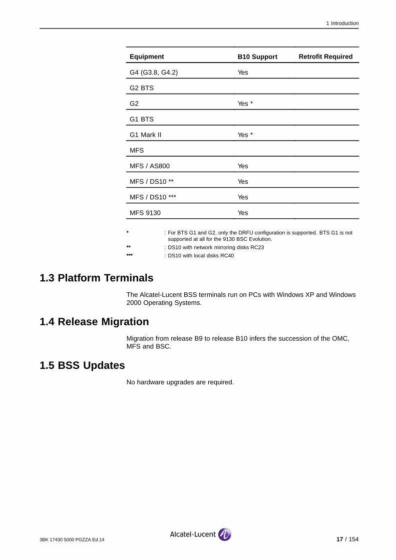
1.2 Supported Hardware Platforms, Restrictions and RetrofitsThe following table lists the Alcatel-Lucent hardware platforms supported by theBSS, and the corresponding restrictions and retrofits.
Equipment B10 Support Retrofit Required
BSC
9120 BSC Yes
9130 BSC Evolution Yes
TC
G2 TC Yes
9125 Compact TC Yes
BTS
9110 Micro BTS, 9110-E MicroBTS
Yes
G3, G3.5 Yes
16 / 154 3BK 17430 5000 PGZZA Ed.14
1 Introduction
Equipment B10 Support Retrofit Required
G4 (G3.8, G4.2) Yes
G2 BTS
G2 Yes *
G1 BTS
G1 Mark II Yes *
MFS
MFS / AS800 Yes
MFS / DS10 ** Yes
MFS / DS10 *** Yes
MFS 9130 Yes
* : For BTS G1 and G2, only the DRFU configuration is supported. BTS G1 is notsupported at all for the 9130 BSC Evolution.
** : DS10 with network mirroring disks RC23
*** : DS10 with local disks RC40
1.3 Platform TerminalsThe Alcatel-Lucent BSS terminals run on PCs with Windows XP and Windows2000 Operating Systems.
1.4 Release MigrationMigration from release B9 to release B10 infers the succession of the OMC,MFS and BSC.
1.5 BSS UpdatesNo hardware upgrades are required.
3BK 17430 5000 PGZZA Ed.14 17 / 154

1 Introduction
1.6 New B10 Features and Impacted SectionsThe following table lists the new B10 features and provides links to impactedsections of this document.
New B10 Features Impacted Sections
MX Capacity Improvements Rules and Assumptions (Section 4.3.4)
9130 Capabilities (Section 4.3.3)
DTM Dual Transfer Mode (Section 3.6.3)
Multiple CCCH Multiple CCCH (Section 4.4.2)
TC IP supervision, STM-1 Architecture (Section 5.3.1)
Rules and Dimensioning (Section 5.3.2)
SS7 Links (Section 8.5.3)
EDA Extended Dynamic Allocation (Section 3.6.4)
AMR-WB, TFO Adaptive Multi-Rate Speech Codec (Section 3.9)
Architecture (Section 5.3.1)
GboIP Gb over IP (Section 6.4.4)
SUM-X 9100 BTS Configuration (Section 3.2.2)
18 / 154 3BK 17430 5000 PGZZA Ed.14

2 BSS Overview
2 BSS Overview
This section describes the Alcatel-Lucent BSS, and corresponding featuresand functions.
3BK 17430 5000 PGZZA Ed.14 19 / 154

2 BSS Overview
2.1 IntroductionThe GSM Radio System (GRS) is a set of hardware and software equipmentprovided by Alcatel-Lucent to support the radio part of the GSM network. TheGRS comprises one OMC-R and one or more BSS. The OMC-R supervisesone or more BSS.
The BSS provides radio access for Mobile Stations (MS) to the PLMN. Thereare one or more GRS per PLMN.
The following figure shows a BSS with GPRS. All BSS operating over thefield are with/without data service.
A Interface
MS
A Interface
MSC
BSC BTS
BTS
TC
Ater−mux Interface
MFS
BSC
BTS
BTS
BTS
GRS
TC
Ater−mux Interface
BSS
MS
SGSN
BTS
BSS
AbisInterface
Abis Interface
MFS
GPRS OMC−R
Um
Um
Gs
MSC
Gb Interface
Figure 1: BSS with GPRS
The different Network Elements (NE) within the BSS are:
The Base Station Controller (BSC)
The Transcoder (TC)
The Base Transceiver Station (BTS)
The Multi BSS Fast packet Server (MFS).
20 / 154 3BK 17430 5000 PGZZA Ed.14

2 BSS Overview
The BSS interfaces are:
The Um interface (air or radio interface), between the MS and the BTS
The Abis interface, used to connect the BTS to the BSC
The Atermux interface used to connect:
The BSC to the TC and/or the MFS
The MFS to the TC
The A interface, used to connect the TC to the MSC
The Gb interface, used to connect the MFS to the SGSN (directly, or through
the TC and the MSC).
Note: This document does not describe the Gs interface, between the MSC and theSGSN, as it is not considered to be part of the BSS. For more information aboutthis interface, refer to the BSS System Description.
For specific information about the LCS dedicated interfaces, refer to LCS inBSS (Section 6.4.2).
Given that the transmission architecture depends on GPRS, there are twopossible transmission architectures:
Transmission architecture with Circuit Switched (CS) only
Transmission architecture with CS and Packet Switched (PS).
3BK 17430 5000 PGZZA Ed.14 21 / 154

2 BSS Overview
2.2 Transmission Architecture with CS OnlyThis section provides information about static Abis only.
The following figure shows the overall transmission architecture with CS only,inside the BSS.
BTS
BSC TC
MSC
Ater−mux Interface
A Interface
The transmission interfaces are:
The Abis interface, between the BIE BTS and the BIE BSC
The Ater interface, between the SM and the DTC inside the BSC, and
between the SM and the TRCU inside the TC
The Atermux interface, between the BSC-SM and the TC-SM
The A interface, between the TRCU and the MSC.
The Abis, Ater, Atermux and A are E1 interfaces structured in 32 timeslots (TS).
The TS are numbered from TS0 to TS31.
Note: Microwave equipment is external to and independent of Alcatel-Lucenttransmission equipment, however, in some cases, the microwave can behoused in the transmission equipment rack and in the BTS.
For 9130 BSC, the SM no longer exists.
22 / 154 3BK 17430 5000 PGZZA Ed.14

2 BSS Overview
2.3 Transmission Architecture with CS and PSPS is directly linked to GPRS and related MFS platforms.
The following figures represent the MFS with its physical interfaces, whenconnected to the network.
BTS
BSC TC
MSC
Ater−mux Interface
AInterface
Ater−mux Interface
MFS
SGSN
Frame RelayGb
Interface
MFS−TC InterfaceMixed CS/GPRSCS TS
GPRS TSConversionof Protocol
Figure 2: Transmission Architecture with CS and PS (1)
BTS
BSC TC
MSC
GbInterface
MFS
SGSN
MFS−TC InterfaceMixed CS/GPRS
AtermuxCS TS
GPRS TSConversionof Protocol
Frame Relay
Figure 3: Transmission Architecture with CS and PS (2)
In addition to the interfaces defined in Transmission Architecture with CS Only(Section 2.2), the MFS uses the following physical interfaces:
The MFS-BSC interface, which is the Atermux interface (a 2Mbit/s PCM linkcarrying 32 TS at 64Kbit/s). The Atermux interface can be fully dedicated
to GPRS (only PS conveyed), or mixed CS/GPRS. In this case, the CSchannels (called CICs) coexist with GPRS channels (called GICs) on
the same link.
The MFS-TC interface, which is also a 2Mbit/s PCM link carrying CS only,GPRS only, or mixed CS/GPRS channels. The Gb interface can be routed
through the TC for SGSN connection. While GSL is used between theBSC and MFS for signaling and not for traffic, the GCH is used between
the BTS and MFS.
3BK 17430 5000 PGZZA Ed.14 23 / 154

2 BSS Overview
The MFS-SGSN interface carries the Gb interface when there is a dedicatedMFS-SGSN link and the MSC-SGSN interface carries the Gb interface if
Gb extraction at the MSC is used. These interfaces can cross a FrameRelay network (or not).
Note: The MFS can connect directly to the MSC (that is, without crossing the TC) forcabling facilities, however this still results in an MFS-SGSN interface, becausethe MSC only cross-connects the GPRS traffic.
2.4 PLMN InterworkingA foreign PLMN is a PLMN other than the PLMN to which OMC-R internal cellsbelong. Only cells external to the OMC-R can belong to a foreign PLMN. Allinternal cells must belong to own OMC PLMN. Both OMC-R owned cells andcells which are external to the OMC-R can belong to the primary PLMN.
The Alcatel-Lucent BSS supports:
Outgoing 2G to 3G handovers
Incoming inter-PLMN 2G to 2G handovers
Outgoing inter-PLMN 2G to 2G handovers
Inter-PLMN 2G to 2G cell reselections
Multi-PLMNThe Multi-PLMN feature allows operators to define several primary PLMN,in order to support network sharing. Inter-PLMN handovers and cellreselections between two different primary PLMN are supported.The Alcatel-Lucent BSS supports several primary PLMN (at least one, up tofour). An OMC-R therefore manages at least one (primary) PLMN and upto eight PLMN (four primary and four foreign).
The OMC-R (and the Tool Chain) is by definition of the feature itself alwaysshared between the different primary PLMN, however:
The MFS can be shared
The BSC cannot be shared
The Abis transmission part can be shared
The transcoder part can be shared.
It is not allowed to modify the PLMN friendly name of a cell, even if theMulti-PLMN feature is active and several PLMN are defined on the OMC-R side.
The primary PLMN cannot be added, removed or modified online.
Customers no longer need to ensure CI (or LAC/CI) unicity over all PLMNinvolved in their network.
With regard to clock synchronization, the only constraint is that when the MFSis connected to different SGSN, these SGSN are not necessarily synchronized.If they are not synchronized, central clocking and cascade clocking cannotbe used on the MFS side.
24 / 154 3BK 17430 5000 PGZZA Ed.14

3 BTS Configurations
3 BTS Configurations
This section describes the Alcatel-Lucent BTS, and corresponding featuresand functions.
3BK 17430 5000 PGZZA Ed.14 25 / 154

3 BTS Configurations
3.1 Introduction to the BTS
3.1.1 BTS in BSS
The following figure shows the location of the BTS inside the BSS.
BTS
Abis
Abis
Atermux
A
Gb
OMC −R
IMT
SGSN
BSC TC
MFS
(PCU)
MSC
Gb
Figure 4: BTS in the BSS
3.1.2 BTS Generation Summary
The following table lists the successive BTS generations, along with thecorresponding commercial name.
G1 BTS G2 BTS 9100 BTS Evolution
G1 BTS G2 BTS G3 BTS G4 BTS (*)
MK2 Mini Std G3 9110MicroBTS
G3.5 G3.8 G4.2 9110-EMicroBTS
MBS
Note: *: G3.8 and G4.2 are the TD names used respectively for Evolution Step 1and Evolution Step 2.
The BTS are grouped into the following families:
The 9110 Micro BTS (which corresponds to the micro BTS 9110 Micro BTS),and the 9110-E (which corresponds to the 9110-E Micro BTS micro BTS)
The 9100 BTS, which includes all 9100 BTS, but not the micro BTS.
26 / 154 3BK 17430 5000 PGZZA Ed.14

3 BTS Configurations
3.2 9100 BTS
3.2.1 9100 BTS Architecture
The 9100 BTS is designed with the following three levels of modules tocover many cell configuration possibilities, including omni or sectored cellsconfigurations:
The antenna coupling level, which consists of ANX, ANY, ANC, AGX,
AGY, AGC and ANB.
The TRE modules which handle the GSM radio access
The BCF level implemented in the SUM, which terminates the Abis interface.
Note: The above-mentioned architecture does not include the micro BTS.
3.2.2 9100 BTS Configuration
The 9100 BTS family began with the G3 BTS, whose architecture is describedin 9100 BTS Architecture (Section 3.2.1).
Further evolutions were introduced, with the G3.5, G4 variants
The G3.5 BTS, which is a G3 BTS with new power supply modules
The G4 BTS Step 1 (also referred to within TD as the G3.8), which is a G3.5
BTS in which the following modules are redesigned:
SUMA, which is the new SUM board
SUM-X, which integrates the Transmission function, the OMU function
and the Master Clock function. SUM-X provides the BTS with theEthernet interfaces
ANC, which is a new antenna network combining a duplexer and
a wide band combiner
New power supply modules which are compatible with BTS subracks.
G4 BTS Step 2 (also referred to within TD as the G4.2) introduces a new
TRE with EDGE hardware capability, including:
CBO, which is the compact outdoor BTS
MBS, which provides multistandard cabinets with the following G4.2
modules:
MBI3, MBI5 for indoor use
MBO1, MBO2, MBO1E, MBO2E for outdoor use.
The 9100 BTS family also includes the following micro BTS:
9110 Micro BTS
9110-E Micro BTS.
3BK 17430 5000 PGZZA Ed.14 27 / 154
3 BTS Configurations
3.2.2.1 Product PresentationThere are different types of cabinets:
The indoor cabinet, which exists in different sizes:
Mini
Medi
MBI3
MBI5
The outdoor cabinet, which exists in different sizes and packaging:
Mini
Medi
Micro
CPT2
CBO
MBO1
MBO1E
MBO2
MBO2E
The different TRE types:
G3 TRE
EDGE TRA
TWIN TRA with the following capabilities:
2 TRE Support
Tx Div Capability
4 Rx Div Support.
28 / 154 3BK 17430 5000 PGZZA Ed.14

3 BTS Configurations
3.2.2.2 9100 BTS DimensioningThe following table lists the extension and reduction capacity rules for the9100 BTS.
Extension / ReductionConfiguration
Physical Logical
BTS
Minimum Maximum Minimum
9100 BTS 1 TRE* Up to 24 TRE 1 to 6 Sectors 1 TRE 1 TRE
9110 Micro BTSMicro-BTS
2 TRE Up to 6 TRE 1 to 6 Sectors 2 TRE 1 TRE
9110-E Micro BTSMicro-BTS
2 TRE Up to 12 TRE 1 to 6 Sectors 2 TRE 1 TRE
* : TWIN modules are required in order to attain 24 TRE. In this case, the minimum for the physical extension step is 1TWIN module (2 TRE).
Table 1: 9100 BTS Minimum and Maximum Capacity
The 6 or 12 TRE are configured with 3 or 6 modules.
The following table summarizes the typical GSM 900, GSM 1800 and GSM1900 configurations.
These configurations constitute only a subset of the possible configurations.
Network GSM 850MHz, 900 MHz, 1800 MHz, 1900 MHz
Indoor / Outdoor Indoor Outdoor
Cabinet size Mini Medi Mini Medi
Number of TRE 1 sectors 1x2 to 1x4 1x2 to 1x12 1x2 to 1x4 1x2 to 1x12
2 sectors 2x1 to 2x2 2x2 to 2x6 2x1 to 2x2 2x2 to 2x6
3 sectors 3x1 3x1 to 3x4 3x1 to 3x2 3x1 to 3x4
6 sectors 6x1 to 6x4 6x1 to 6x4
Table 2: Typical GSM 900 and GSM 1800/1900 Configurations
3BK 17430 5000 PGZZA Ed.14 29 / 154
3 BTS Configurations
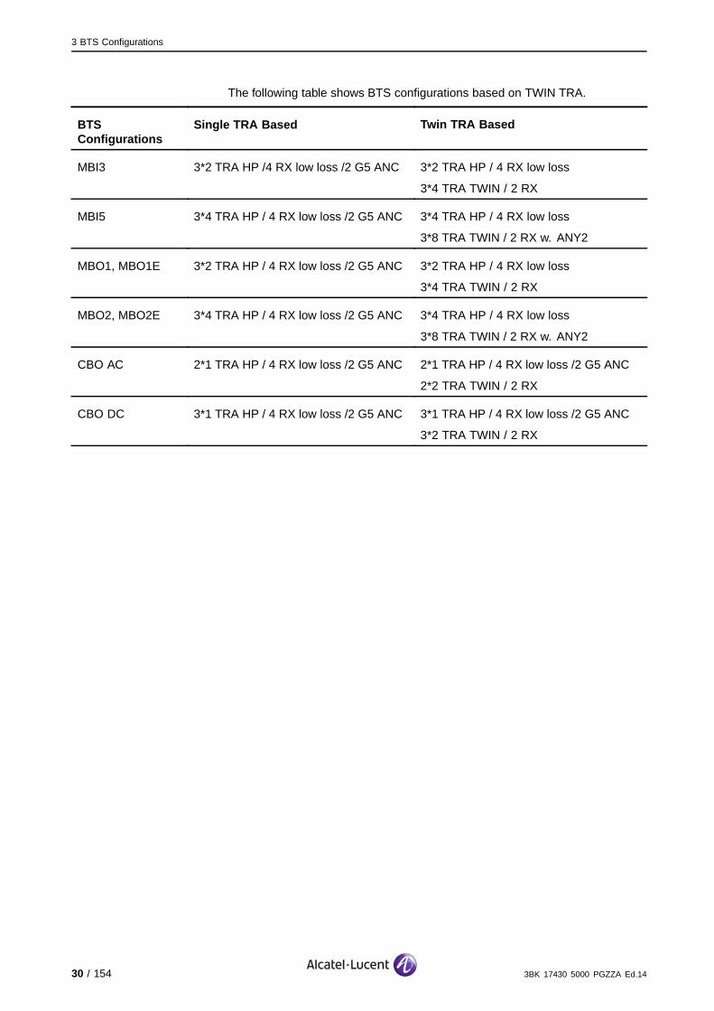
The following table shows BTS configurations based on TWIN TRA.
BTSConfigurations
Single TRA Based Twin TRA Based
MBI3 3*2 TRA HP /4 RX low loss /2 G5 ANC 3*2 TRA HP / 4 RX low loss
3*4 TRA TWIN / 2 RX
MBI5 3*4 TRA HP / 4 RX low loss /2 G5 ANC 3*4 TRA HP / 4 RX low loss
3*8 TRA TWIN / 2 RX w. ANY2
MBO1, MBO1E 3*2 TRA HP / 4 RX low loss /2 G5 ANC 3*2 TRA HP / 4 RX low loss
3*4 TRA TWIN / 2 RX
MBO2, MBO2E 3*4 TRA HP / 4 RX low loss /2 G5 ANC 3*4 TRA HP / 4 RX low loss
3*8 TRA TWIN / 2 RX w. ANY2
CBO AC 2*1 TRA HP / 4 RX low loss /2 G5 ANC 2*1 TRA HP / 4 RX low loss /2 G5 ANC
2*2 TRA TWIN / 2 RX
CBO DC 3*1 TRA HP / 4 RX low loss /2 G5 ANC 3*1 TRA HP / 4 RX low loss /2 G5 ANC
3*2 TRA TWIN / 2 RX
30 / 154 3BK 17430 5000 PGZZA Ed.14

3 BTS Configurations
The following table shows the TWIN operation modes supported by the differentBTS hardware generations.
TWIN TRA 2TRX Modeboth on samesector
2TRX Modeboth on diff.sectors
1TRX Modewith TX Div.
1TRX Modew/o TX Div.
BTS- 9100G3- Mini-Indoor yes yes no 1) no 1)
BTS- 9100G3 & G3.5 -Mini -Outdoor yes yes no 1) no 1)
BTS- 9100G3 & G3.5 -Medi -Outdoor yes yes no 1) no 1)
BTS- 9100G4 -Mini -Indoor yes yes no 1) no 1)
BTS- 9100G4- Medi- Indoor yes yes no 1) no 1)
BTS- 9100G3.8 -Mini -Outdoor yes yes no 1) no 1)
BTS- 9100G3.8 -CPT2 -Outdoor yes yes no 1) no 1)
BTS -9100G3.8 -Medi -Outdoor yes yes no 1) no 1)
BTS -9100G4 -MBI-3 yes yes yes 2) yes
BTS -9100G4 -MBI-5 yes yes yes 2) yes
BTS -9100G4 -MBO-1 yes yes no 1) no 1)
BTS -9100G4 -MBO-2 yes yes no 1) no 1)
BTS -9100G4 -CBO yes yes yes 2) yes
BTS -9100G5 -MBO-1E yes yes yes 2) yes
BTS -9100G5 -MBO-2E yes yes yes 2) yes
Note: 1): Given that the cell planning is done for these network elements, the TXDiv. feature is not supported.
2): The ordered configuration for TX Div. will be delivered from the factory bydefault with the 2TRX Mode cabled in different sectors and must be configuredonsite for TX Div.
3BK 17430 5000 PGZZA Ed.14 31 / 154

3 BTS Configurations
The following table summarizes the typical Multiband 900/1800 BTSconfigurations.
These configurations constitute only a subset of the possible configurations.
Network Multiband BTS or Multiband Cell
Cabinet size Medi/ Number of TRE
4 sectors 2x2 GSM 900 & 2x4 GSM 1800
2x4 GSM 900 & 2x2 GSM 1800
6 sectors 3x2 GSM 900 & 3x2 GSM 1800 (outdoor only)
Diversity 4 sectors: Yes
6 sectors: Yes
Table 3: Typical Multiband Configuration G3 BTS
3.2.2.3 9100 BTS RulesThe same BTS supports all four types of TRA on a cell.
SUMA is required to support TWIN.
A second Abis is necessary for EDGE and for more then 12 TRX, exceptfor small and medium BTS.
The BTS must not contain any G3 TREs for a configuration with more than12 TREs.
3.2.2.4 Extended Cell ConfigurationIt is possible to have up to 12 CS+PS capable TRX, including the BCCHTRX, in each cell (inner and outer).
M4M and M5M do not support extended cell configurations.
3 extended cell per BTS are allowed.
Multiple CCCH is not supported in Extended Cell.
SUMP does not support the extended cell feature.
The inner and the outer of the extended cell must have the sameACCESS_BURST_TYPE parameter value.
32 / 154 3BK 17430 5000 PGZZA Ed.14

3 BTS Configurations
3.2.2.5 Mixture of 9110-E Micro BTS and 9110 Micro BTS BTSThe following four configurations rules apply for pure 9110-E Micro BTS and9110 Micro BTS/9110-E Micro BTS mixed configurations:
A maximum of three hierarchic levels (master, upper and lower slave)are allowed
Each 9110 Micro BTS upper slave terminates the master-slave link, which is
the Inter Entity Bus (IEB)
9110 Micro BTS is not allowed in the lower slave position
9110-E Micro BTS must be set as the master in 9110 Micro BTS/9110-E
Micro BTS mixed configurations.
The following figure shows a mixed 9110 Micro BTS/9110-E Micro BTSstandard configuration.
MasterM5M
Upper Slave 1M5M
Lower Slave 11M5M
Lower Slave 12M5M
Upper Slave 2M4M
3.2.2.6 Mixed configuration G3 and G4In the case of a mixed hardware configuration in a cell with both G3 andG4 TREs in the same cell, the E-GSM TRX is associated to G4 TRE andP-GSM TRX to G3 TRE.
3BK 17430 5000 PGZZA Ed.14 33 / 154
3 BTS Configurations
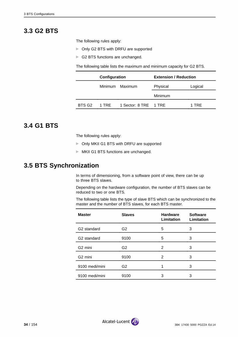
3.3 G2 BTSThe following rules apply:
Only G2 BTS with DRFU are supported
G2 BTS functions are unchanged.
The following table lists the maximum and minimum capacity for G2 BTS.
Configuration Extension / Reduction
Physical LogicalMinimum Maximum
Minimum
BTS G2 1 TRE 1 Sector: 8 TRE 1 TRE 1 TRE
3.4 G1 BTSThe following rules apply:
Only MKII G1 BTS with DRFU are supported
MKII G1 BTS functions are unchanged.
3.5 BTS SynchronizationIn terms of dimensioning, from a software point of view, there can be upto three BTS slaves.
Depending on the hardware configuration, the number of BTS slaves can bereduced to two or one BTS.
The following table lists the type of slave BTS which can be synchronized to themaster and the number of BTS slaves, for each BTS master.
Master Slaves HardwareLimitation
SoftwareLimitation
G2 standard G2 5 3
G2 standard 9100 5 3
G2 mini G2 2 3
G2 mini 9100 2 3
9100 medi/mini G2 1 3
9100 medi/mini 9100 3 3
34 / 154 3BK 17430 5000 PGZZA Ed.14

3 BTS Configurations
3.6 Physical Channel Types
3.6.1 GSM
In terms of TS content, there are several possible configurations, the mostrelevant of which are:
Traffic channels (TCH)
Signaling channels:
BCC = FCCH + SCH + BCCH + CCCH
CBC = FCCH + SCH + BCCH + CCCH + SDCCH/4 + SACCH/4
SDC = SDCCH/8 + SACCH/8.
where
BCCH transports broadcast system information
SDCCH transports signalling outside a call. It can be static (fixed positionon the TS), or dynamic (variable existence in time).
Note: It is possible to define two CBCH channels for cells used for SMS-CB:
The basic CBCH channel
The extended CBCH channel.
If the basic CBCH channel is configured, the extended CBCH channel can beoptionally configured. The extended CBCH channel is managed in the samemanner as the basic CBCH channel. When the initial SDCCH number in a cellis small, a reduction in the number of SDCCH due to the configuration of theCBCH can increase the SDCCH average load. In such a case, the operatormay need to add one SDCCH TS.
3.6.2 GPRS
GPRS radio timeslots (PDCH) are dynamically allocated according to thefollowing, customer-defined parameters:
MIN_PDCH defines the minimum number of PDCH TS per cell
MAX_PDCH defines the maximum number of PDCH TS per cell
MAX_PDCH_HIGH_LOAD defines the maximum number of PDCH TS per cellin the case of CS traffic overload.
Those parameters allow the operator to prioritize CS traffic versus GPRS trafficin order, for example, to avoid a QoS drop while introducing GPRS.
The following quality parameters can also be used:
N_TBF_PER_SPDCH defines the number of mobile stations that can share thesame PDCH
MAX_PDCH_PER_TBF defines the maximum number of PDCHs allocated
to a single (E)GPRS connection.
3BK 17430 5000 PGZZA Ed.14 35 / 154

3 BTS Configurations
3.6.3 Dual Transfer Mode
A dual transfer mode capable mobile station can use a radio resource for CStraffic and simultaneously one or several radio resources for PS traffic.
Requirements:
The Gs interface is a prerequisite to fully support the DTM feature. However,the BSS does not forbid the activation of the DTM feature if the Gs interface
is not supported (i.e. when the network mode of operation is set to NMOII or NMO III)
Cells where MAX_PDCH_HIGH_LOAD < 2 ((E)GPRS) is mandatory for DTM
operation, and at least two PDCHs are required in the PS zone for allocationof DTM resources to (at least) one DTM call)
Handover causes with low priority are disabled with a mobile station in DTM.
DTM is supported:
For both GPRS and EGPRS
As (E)GPRS is preferentially offered in macro cells, the BSS ensuresthat at least one PDCH can be used in micro cells to re-direct the mobile
station towards the macro cells. This means that the BSS allows a PDCHused by an mobile station operating in DTM mode to be shared by other
(E)GPRS mobile station
Only multislot operation DTM MSs are supported.
DTM is not supported in the following cases:
Single slot operation DTM MSs are not supported in the Alcatel-Lucent BSS
DTM is not supported in following types of cells:
Non-9100 BTS
Extended cells.
DTM is not supported in half rate configurations.
36 / 154 3BK 17430 5000 PGZZA Ed.14

3 BTS Configurations
Concerning power control management:
In the uplink direction:
On the mobile stations side, the power control in different timeslots isindependent and with no restriction on the difference of power transmittedin adjacent timeslots. Therefore, there are no specific requirements inthe uplink direction:
On the TCH, the mobile stations transmits with the output power
computed based on the BSS power command (if UL power controlis activated in the CS domain)
On the PDCH, the mobile stations transmits with the output power asa function of the GPRS power control parameters GAMMA_TNx and
ALPHA and the signal level received in the DL.
In the downlink direction:The BTS output power variation between all blocks addressed to a particularmobile stations within a TDMA frame does not exceed 10 dB for mobilestations operating in DTM. Moreover, the power difference betweencontiguous CS and PS timeslots must be in the same range of 10 dB.
3.6.4 Extended Dynamic Allocation
Extended Dynamic Allocation (EDA) is an extension of the basic DynamicAllocation (E)GPRS MAC mode to allow higher throughput in uplink for type 1mobile stations (supporting the feature) through the support of more than tworadio transmission timeslots.
With the EDA mode, the mobile station detects an assigned USF value for anyassigned uplink PDCH and allows the mobile station to transmit on that PDCHand all higher numbered assigned PDCHs.
The mobile station does not need to monitor all the downlink PDCHcorresponding to its allocated uplink PDCH, which allows the type 1 mobilestation to support configurations with more uplink timeslots (and thus with lessdownlink timeslots).
The radio configurations is only used if the uplink TBF (in EDA mode) can bealone on its assigned uplink timeslots and not in front of downlink timeslotssupporting the PACCH channel of at least one downlink TBF not belongingto the same mobile station.
Rules:
Only multislot classes 1-12 are supported
EDA operations in DTM mode are not supported
EDA operations are not supported in the case of RT TBF and RT PFC
EDA is only used in UL in TS configurations for which (Dynamic Allocation)DA is not possible (if both EDA and DA are possible in UL for a given
TS configuration, then DA is used)
As the shifted-USF operation is not supported, EDA will not be handled for
mobile stations whose multislot class is 7 (1+3 configuration).
3BK 17430 5000 PGZZA Ed.14 37 / 154
3 BTS Configurations
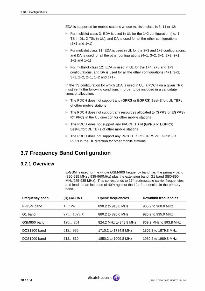
EDA is supported for mobile stations whose multislot class is 3, 11 or 12:
For multislot class 3: EDA is used in UL for the 1+2 configuration (i.e. 1
TS in DL, 2 TSs in UL), and DA is used for all the other configurations(2+1 and 1+1)
For multislot class 11: EDA is used in UL for the 2+3 and 1+3 configurations,
and DA is used for all the other configurations (4+1, 3+2, 3+1, 2+2, 2+1,1+2 and 1+1)
For multislot class 12: EDA is used in UL for the 1+4, 2+3 and 1+3
configurations, and DA is used for all the other configurations (4+1, 3+2,3+1, 2+2, 2+1, 1+2 and 1+1).
In the TS configuration for which EDA is used in UL, a PDCH on a given TRXmust verify the following conditions in order to be included in a candidatetimeslot allocation:
The PDCH does not support any (GPRS or EGPRS) Best-Effort UL TBFs
of other mobile stations
The PDCH does not support any resources allocated to (GPRS or EGPRS)RT PFCs in the UL direction for other mobile stations
The PDCH does not support any PACCH TS of (GPRS or EGPRS)
Best-Effort DL TBFs of other mobile stations
The PDCH does not support any PACCH TS of (GPRS or EGPRS) RT
PFCs in the DL direction for other mobile stations.
3.7 Frequency Band Configuration
3.7.1 Overview
E-GSM is used for the whole GSM-900 frequency band, i.e. the primary band(890-915 MHz / 935-960MHz) plus the extension band, G1 band (880-890MHz/925-935 MHz). This corresponds to 174 addressable carrier frequenciesand leads to an increase of 40% against the 124 frequencies in the primaryband.
Frequency span (U)ARFCNs Uplink frequencies Downlink frequencies
P-GSM band 1.. 124 890.2 to 915.0 MHz 935.2 to 960.0 MHz
G1 band 975.. 1023, 0 880.2 to 890.0 MHz 925.2 to 935.0 MHz
GSM850 band 128... 251 824.2 MHz to 848.8 MHz 869.2 MHz to 893.8 MHz
DCS1800 band 512.. 885 1710.2 to 1784.8 MHz 1805.2 to 1879.8 MHz
DCS1900 band 512.. 810 1850.2 to 1909.8 MHz 1930.2 to 1989.8 MHz
38 / 154 3BK 17430 5000 PGZZA Ed.14

3 BTS Configurations
3.7.2 Compatibility
The following table shows TRE generation equipment and the correspondingradio bands.
Multiband (BTS or Cell)
GSM 850 GSM 900 GSM1800
GSM1900
850 /1800
850 /1900
900 /1800
900 /1900
G3/G4 Yes (*) E-GSM Yes Yes Yes Yes Yes Yes
9110-EMicro BTS
Yes E-GSM Yes Yes Yes Yes Yes Yes
9110Micro BTS
N.A P-GSM Yes N.A N.A N.A Yes N.A
G2 N.A E-GSM Yes Yes N.A N.A N.A N.A
G1 MKII N.A Yes N.A N.A N.A N.A N.A N.A
* : The BTS can be a G3 BTS, but the TRE is a G4.2 TRE.
Table 4: Frequency Band Configuration
3.7.3 Rules
From functional point of view, there are two types of multiband behavior:
Multiband BTSThe frequency bands (850/1800, or 850/1900, or 900/1800) are used indifferent sectors of the BTS. There are two BCCH carriers, one in the sectorwith frequency band 1, and another one in the sector with frequency band 2.
Multiband cellThe sector (cell) is configured with TRX in band 1, and TRX in band 2. Onlyone BCCH carrier is configured for the sector.
Only CS is supported by the G1 band TRX and by the inner zone TRXs of aconcentric or a multiband cell
3BK 17430 5000 PGZZA Ed.14 39 / 154
3 BTS Configurations
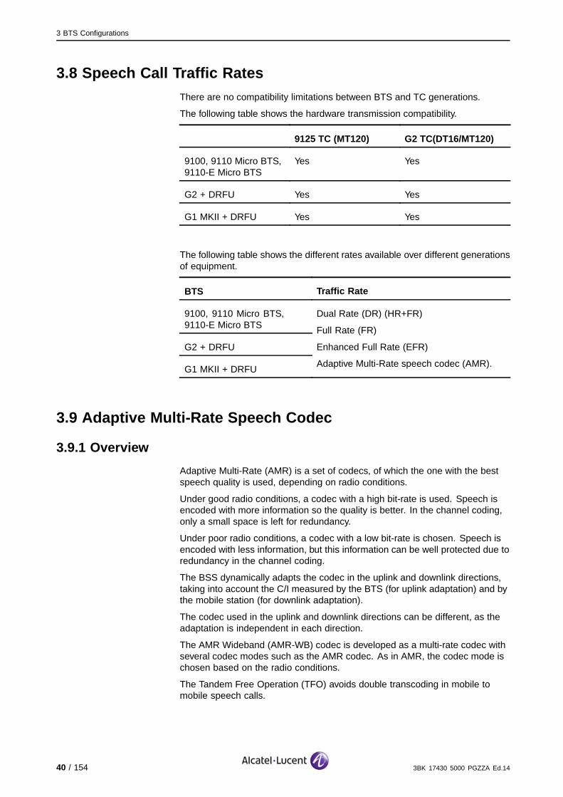
3.8 Speech Call Traffic RatesThere are no compatibility limitations between BTS and TC generations.
The following table shows the hardware transmission compatibility.
9125 TC (MT120) G2 TC(DT16/MT120)
9100, 9110 Micro BTS,9110-E Micro BTS
Yes Yes
G2 + DRFU Yes Yes
G1 MKII + DRFU Yes Yes
The following table shows the different rates available over different generationsof equipment.
BTS Traffic Rate
9100, 9110 Micro BTS,9110-E Micro BTS
G2 + DRFU
G1 MKII + DRFU
Dual Rate (DR) (HR+FR)
Full Rate (FR)
Enhanced Full Rate (EFR)
Adaptive Multi-Rate speech codec (AMR).
3.9 Adaptive Multi-Rate Speech Codec
3.9.1 Overview
Adaptive Multi-Rate (AMR) is a set of codecs, of which the one with the bestspeech quality is used, depending on radio conditions.
Under good radio conditions, a codec with a high bit-rate is used. Speech isencoded with more information so the quality is better. In the channel coding,only a small space is left for redundancy.
Under poor radio conditions, a codec with a low bit-rate is chosen. Speech isencoded with less information, but this information can be well protected due toredundancy in the channel coding.
The BSS dynamically adapts the codec in the uplink and downlink directions,taking into account the C/I measured by the BTS (for uplink adaptation) and bythe mobile station (for downlink adaptation).
The codec used in the uplink and downlink directions can be different, as theadaptation is independent in each direction.
The AMR Wideband (AMR-WB) codec is developed as a multi-rate codec withseveral codec modes such as the AMR codec. As in AMR, the codec mode ischosen based on the radio conditions.
The Tandem Free Operation (TFO) avoids double transcoding in mobile tomobile speech calls.
40 / 154 3BK 17430 5000 PGZZA Ed.14

3 BTS Configurations
3.9.2 Rules and Dimensioning
The following table provides a list of AMR codecs.
Codec Bit Rate Full Rate Half Rate
12.2 Kbit/s X
10.2 Kbit/s X
7.95 Kbit/s X X (*)
7.40 Kbit/s X X
6.70 Kbit/s X X
5.90 Kbit/s X X
5.15 Kbit/s X X
4.75 Kbit/s X X
* : Not supported by the Alcatel-Lucent BSS.
Table 5: AMR Codec List
During a call, a subset of 1 to 4 codecs is used, configured by O&M on aper BSS basis.
A different number of codecs and different subsets can be defined for FR (oneto four codecs out of the eight codecs available), and for HR (one to fourcodecs out of the five codecs available).
The codec subset is the same in uplink and downlink.
3BK 17430 5000 PGZZA Ed.14 41 / 154

3 BTS Configurations
The following table provides a list of AMR-WB codecs. Only codec bit-rates inbold are available.
Codec Bit RateAMR WB
Full Rate Half Rate GMSK 8-PSK
23.85 kbit/s x x
15.85 kbit/s x x
x x
x x
12.65 kbit/s
x x
x x
x x
8.85 kbit/s
x x
x x
x x
6.60 kbit/s
x x
Table 6: AMR-WB Codec List
The lowest bit rate providing excellent speech quality in a clean environment is12.65 kbit/s. Higher bit rates are useful in background noise conditions and inthe case of music. Also, lower bit rates of 6.60 and 8.85 provide reasonablequality, especially if compared to narrow band codecs.
On the AMR-WB Air interface, only GMSK is used for FR TCH.
The AMR-WB GMSK mandatory rules are:
AMR_WB_GMSK_THR_1+AMR_WB_GMSK_HYST_1<=
AMR_WB_GMSK_THR_2+AMR_WB_GMSK_HYST_2 (regardingAMR-WB thresholds and hysteresis)
AMR_WB_GMSK_THR_1 < AMR_WB_GMSK_THR_2.
The AMR-WB interface is used with the MT120 WB board and the AMR-NBinterface is used with the MT120 NB board.
Supported channel types:
All TCH/WFS: supported
RATSCCH: supported
All O-TCH/WFS, O-TCH/WHS and O-TCH/AHS are not supported.
Note that BTS G1 and G2 does not support AMR-WB.
TC G2, 9125 TC support AMR-WB.
42 / 154 3BK 17430 5000 PGZZA Ed.14

3 BTS Configurations
Intracell handovers for resolution of codec mismatches in TFO are forbidden.Only the critical HO causes are offered to DTM calls.
The following table refers to supported software versions versus hardwareboards and features.
HardwareBoard/Feature
AMR NBwithoutTFO NB
TFO NB TFO FR,HR, EFR
AMR WBincludingTFO WB
Legacy MT120 yes no yes no
MT120-NB yes no yes no
MT120-WB yes no yes yes
Table 7: Software Version versus Hardware Board/Feature
3.10 TRE Packet CapabilityThe value "0" of TRX Preference Mark (TPM) means that the concernedTRX is PS capable.
The following table shows the data service rate available over differentgenerations of equipment.
Up to 9.6Kbit/s
GPRSCS-1and CS-2
GPRSCS-3and CS-4
EGPRSMCS-1to MCS-9
G4 TRE and9110-E Micro BTS
Yes Yes Yes Yes
TWIN TRE Yes Yes Yes Yes
G3 TRE and 9110Micro BTS
Yes Yes Yes
G2 + DRFU Yes Yes
G1 MKII + DRFU Yes Yes
Table 8: Data Call Traffic
3BK 17430 5000 PGZZA Ed.14 43 / 154
3 BTS Configurations
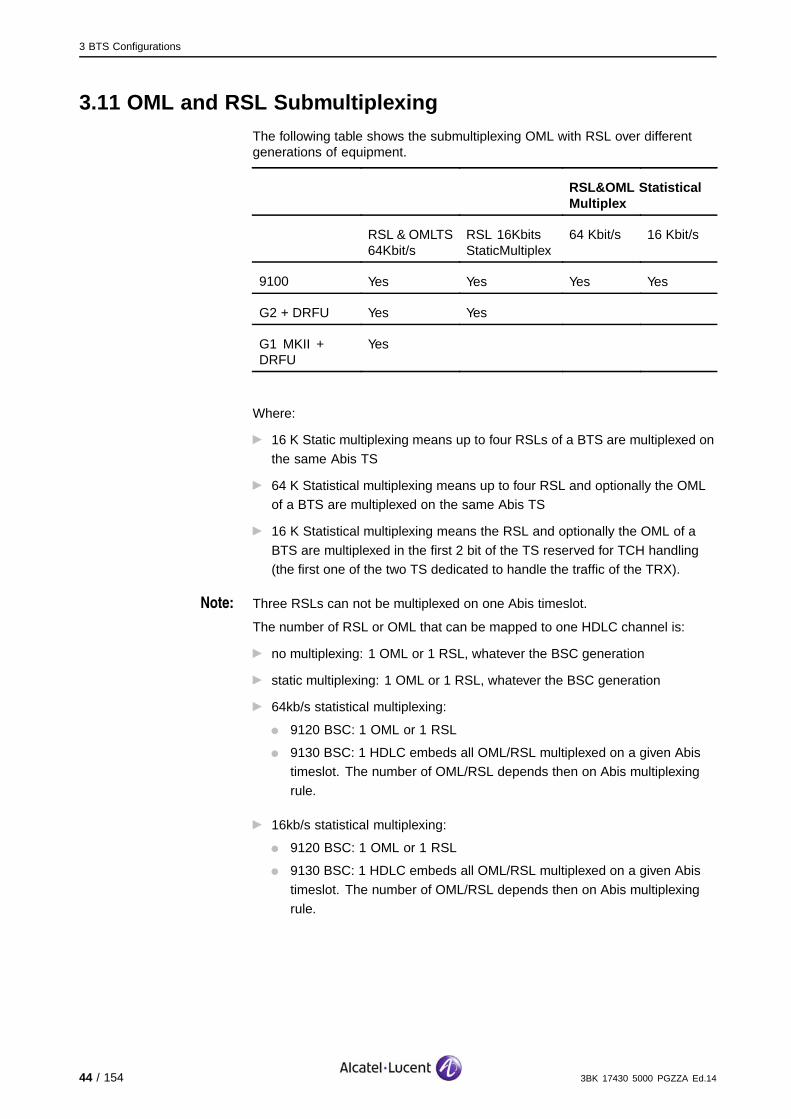
3.11 OML and RSL SubmultiplexingThe following table shows the submultiplexing OML with RSL over differentgenerations of equipment.
RSL&OML StatisticalMultiplex
RSL & OMLTS64Kbit/s
RSL 16KbitsStaticMultiplex
64 Kbit/s 16 Kbit/s
9100 Yes Yes Yes Yes
G2 + DRFU Yes Yes
G1 MKII +DRFU
Yes
Where:
16 K Static multiplexing means up to four RSLs of a BTS are multiplexed on
the same Abis TS
64 K Statistical multiplexing means up to four RSL and optionally the OMLof a BTS are multiplexed on the same Abis TS
16 K Statistical multiplexing means the RSL and optionally the OML of a
BTS are multiplexed in the first 2 bit of the TS reserved for TCH handling(the first one of the two TS dedicated to handle the traffic of the TRX).
Note: Three RSLs can not be multiplexed on one Abis timeslot.
The number of RSL or OML that can be mapped to one HDLC channel is:
no multiplexing: 1 OML or 1 RSL, whatever the BSC generation
static multiplexing: 1 OML or 1 RSL, whatever the BSC generation
64kb/s statistical multiplexing:
9120 BSC: 1 OML or 1 RSL
9130 BSC: 1 HDLC embeds all OML/RSL multiplexed on a given Abistimeslot. The number of OML/RSL depends then on Abis multiplexing
rule.
16kb/s statistical multiplexing:
9120 BSC: 1 OML or 1 RSL
9130 BSC: 1 HDLC embeds all OML/RSL multiplexed on a given Abis
timeslot. The number of OML/RSL depends then on Abis multiplexing
rule.
44 / 154 3BK 17430 5000 PGZZA Ed.14
3 BTS Configurations
3.12 BTS Power LevelThe BTS power can be adjusted further than Unbalanced Output Power orCell Shared.
The BTS power can be reduced by the operator due to the following parameters:
BS_TXPWR_MAX
T3106-D
T3106-F
PWR_ADJUSTMENT.
The first 3 parameters on one side and the last one on other side are computedseparately. If one or the other is changed by the operator, the left one ischanged by the OMC.
At migration time, the following values must be respected:
T3106-DMax (( old value T3106-D ‘AND’ ‘11111111000’), (1104))
T3106-Fold value T3106-F ‘AND’ ‘1111111100’.
These settings are per step of 0.1db.
The computations precision is 0.1db.
3.13 Cell Configurations
3.13.1 Cell Types
The BSS supports a set of cell configurations designed to optimize the reuseof frequencies.
The following profile types characterize the cells:
Cell dimensionMacro up to 35 Km but up to 70 km with extended cells. Micro up to 300meters.
Cell CoverageThere are four types of coverage: single, lower (overlaid), upper (umbrella),and indoor.
Cell PartitionThere are two types of frequency partition: normal or concentric.
Cell RangeThe cell range can be either normal or extended.
Cell Band TypeA cell belongs to 850, 900, 1800 or 1900 bands, or to two frequency bandsin the case of a multiband cell.
The following table describes the cell types.
3BK 17430 5000 PGZZA Ed.14 45 / 154

3 BTS Configurations
Cell Type Dimension Coverage Partition Range
Micro Micro Overlaid Normal Normal
Single Macro Single Normal Normal
Mini Macro Overlaid Normal Normal
Extended Macro Single Normal Extended
Umbrella Macro Umbrella Normal Normal
Concentric Macro Single Concentric Normal
Umbrella-Concentric Macro Umbrella Concentric Normal
Indoor Micro Micro Indoor Normal Normal
46 / 154 3BK 17430 5000 PGZZA Ed.14

3 BTS Configurations
The following table lists the Alcatel-Lucent BSS cell types for multiband cells.
Cell Type Dimension Coverage Partition Range
Micro Micro Overlaid Concentric Normal
Single Macro Single Concentric Normal
Mini Macro Overlaid Concentric Normal
Umbrella Macro Umbrella Concentric Normal
Non extended, non concentric mono-band cells of any type can be converted tomultiband cells by adding TRXs of a different band.
The micro concentric, mini concentric, indoor concentric cells must bemultiband (the allowed FREQUENCY_RANGE is PGSM-DCS1800 orEGSM-DCS1800). This restriction does not apply to external cells.
The Unbalancing TRX Output Power per BTS sector allows unbalancedconfigurations. The level of the output power is no more adapted to the lowerTRE output in the sector. One group of transceivers is configured to transmitwith high output power, the other group is configured to transmit with low outputpower. This configuration is available in concentric cell, where the output powerbalancing is performed on a zone basis instead of on the sector basis.
When is activated, it is recommended to the operator to set the TRX PreferenceMark parameter to 0 for all TRX of the outer zone.
For the extended cell, the following rules apply:
(E)GPRS is supported
NC2 mode is not offered
The Network Assisted Cell Change is not allowed
The (Packet) PSI status procedure is not allowed
The extended inner cell is not declared in the neighbor cells reselection
adjacencies, because it is barred
Up to 12 TRX CS+PS capable, including the BCCH TRX can be offered in
each cell (inner + outer)
The extended inner and outer cells are in the same Routing Area
No frequency hopping is allowed neither in the extended inner cell nor in theextended outer cell for (E)GPRS TRX
In extended cell, the allowed coding schemes are:
CS1... CS4, MCS1...MCS9 in the inner cell for the both directions
CS1... CS4, MCS1...MCS4 in the outer cell for the both directions.
3BK 17430 5000 PGZZA Ed.14 47 / 154

3 BTS Configurations
3.13.2 Frequency Hopping
The frequency hopping types do not reflect the technology used, but ratherthe structure of the hopping laws.
The following table shows the hopping types supported in release B10.
Hopping Type Supported in B10
Non Hopping (NH) X
Base Band Hopping (BBH) X
Radio Hopping (RH) * -
Non Hopping / Radio Hopping (NH/RH) X
NH/RH with Pseudo Non Hopping TRX X
BBH with Pseudo Non Hopping TRX X
* : This hopping mode works only with M1M, M2M that are obsolete.
Baseband hopping (BBH) refers to the number of ARFCN = number of usedTRX. In a structure with two hopping systems, the first one includes all ARFCN,FHS1, the second, all without the BCCH ARFCN, FHS2. The TS1-7 from allTRX get the FHS2. The TS0 from the BCCH TRX is configured with the BCCHARFCN (non hopping) and the other TS0 from the Non BCCH TRX gets FHS1.This is the basic BBH configuration.
Radio hopping or synthesizer frequency hopping (RH) is when the TRX donot get fixed frequency assignments, but can change their frequency fromTS to TS according to a predefined hopping sequence. The number ofapplicable hopping frequencies can be larger then the number of equippedTRX: N(hop) >= N(TRX).
Inside an FHS, it is possible to mix frequencies belonging to the P-GSMband and the G1 band, depending on the RR_EGSM_Alloc_strategy; othermixes are not allowed.
If there are several FHS, all PS TRX have the same FHS.
48 / 154 3BK 17430 5000 PGZZA Ed.14

3 BTS Configurations
3.13.3 Shared Cell
3.13.3.1 OverviewEach BTS can manage one (all BTS generations) or several cells (from G3BTS). In the case of a cell shared by several BTS, is possible to supportup to 16 TRX.
Only the 9100 9100 BTS supports shared cells. In the case of a monobandshared sector, every type of cell is supported except for extended cells.
In general, a BTS comprises several physical sectors. Until release B7, a cellwas mapped on a physical sector. The operator can associate two physicalsectors pertaining to different BTS with one shared sector. This shared sectorcan be mono or bi-band and it can support one cell as a normal sector. It takesthe identity of one of the physical sectors. Between the two sectors, one is themain sector, and the other is the secondary sector.
This allows:
Existing cells to be combined into one (for example, one 900 cell and one
1800 cell in order to get a multi band cell)
Existing cells can be extended only by adding new hardware in a newcabinet, not touching the arrangement of the existing BTSs
Support for 3x8 in two racks.
The linked BTS can still be connected on the Abis side, by the same or adifferent Abis link, the same or different Abis TSU, or by same or differentmultiplexing schemes.
The shared cell requires a specific attribute that must be defined by theoperator (either primary or secondary) at the TRX level.
3.13.3.2 RulesThe following rules apply:
Clock synchronizationThe BTS in a shared cell must be synchronized.
Hardware coverageFor G3 BTS and beyond, generations can be mixed as long as master/slaveconfigurations are possible. Cell sharing is not supported on M5M andM4M, because they cannot be clock synchronized.
Output Power.When a certain sector is extended with another sector, transmission outputpowers can be different. In this case, a software adjustment of the outputpower is performed. There is a separate power adjustment for 900MHz and1800 MHz. In all cases, if there is a power discrepancy, only an alarm issent, without any further consequences, and sectors continue to transmittraffic. In a cell shared over two BTS, only one sector (main or secondary)can support GPRS traffic (not both).The unbalancing TRX output power also applies on shared cells.
3BK 17430 5000 PGZZA Ed.14 49 / 154

3 BTS Configurations
50 / 154 3BK 17430 5000 PGZZA Ed.14

4 BSC Configuration
4 BSC Configuration
This section describes the 9120 and 9130 BSC Evolution, and correspondingfeatures and configurations.
3BK 17430 5000 PGZZA Ed.14 51 / 154

4 BSC Configuration
4.1 BSC in the BSSThe following figure shows the location of the BSC inside the BSS.
BTS
Abis
Abis
Atermux
A
Gb
OMC −R
IMT
SGSN
BSC TC
MFS
(PCU)
MSC
Gb
Figure 5: BSC in the BSS
4.2 9120 BSC
4.2.1 9120 BSC Architecture
The 9120 BSC consists in one switch and three main sub-units types (TSU):
The Abis TSU, which determines the connectivity with BTS
The Ater TSU, which sets the capacity the BSC can handle
The common TSU.
This is shown in the following figure.
BIUA
TCUC
TCUC
TCUC
TCUC
TCUC TCUC TCUC TCUC
AS
DTCC
DTCC
DTCC
DTCC
DTCC
DTCC
DTCC
AS
DTCC
CPRC CPRC CPRC CPRC CPRC CPRC CPRC CPRC
AS
6 x
G.703
Abis
I/F
2 x
G.703
Ater
muxed
I/F
Abis TSU Ater TSU
Common Functions TSU
Group Switch
8 Planes
2 Stages
TSC
TSL
ASMB
ASMB
Q1 bus
Broadcast bus
Figure 6: 9120 BSC Architecture
52 / 154 3BK 17430 5000 PGZZA Ed.14
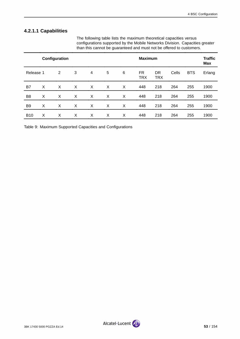
4 BSC Configuration
4.2.1.1 CapabilitiesThe following table lists the maximum theoretical capacities versusconfigurations supported by the Mobile Networks Division. Capacities greaterthan this cannot be guaranteed and must not be offered to customers.
Configuration Maximum TrafficMax
Release 1 2 3 4 5 6 FRTRX
DRTRX
Cells BTS Erlang
B7 X X X X X X 448 218 264 255 1900
B8 X X X X X X 448 218 264 255 1900
B9 X X X X X X 448 218 264 255 1900
B10 X X X X X X 448 218 264 255 1900
Table 9: Maximum Supported Capacities and Configurations
3BK 17430 5000 PGZZA Ed.14 53 / 154

4 BSC Configuration
The following table below lists the parameters that are applicable to allconfigurations across all releases.
B7 B8 B9 B10
CPRC-SYS 2 2 2 2
CPRC-OSI 2 2 2 2
CPRC-BC 2 2 2 2
TRE (FR FU)/ TCU or RSL / TCU 4 4 4 4
TRE (DR FU) / TCU 2 2 2 2
TRE / BTS (9100 BTS) 12 12 24 24
LAPD / TCU 6 6 6 6
Cells or Sectors /BTS 6 6 6 6
TRX / Cell 16 16 16 16
TRX / Cell for GPRS support 16 16 16 16
Max Nb SCCP cnx / BSSAP proc. 128 128 128 128
Frequency Hopping Identifiers 1056 1056 1056 1056
Neighbor Cells 3500 3500 3500 3500
Adjacencies 5400 5400 5400 5400
Table 10: 9120 BSC Globally Applicable Parameters
4.2.1.2 9120 BSC versus G2 TC ConfigurationsThe BSC configuration always has to handle the complete configuration forthe TC, however the TC racks can be under-equipped compared with theBSC configuration.
54 / 154 3BK 17430 5000 PGZZA Ed.14

4 BSC Configuration
4.2.1.3 Rack RulesThe following rules apply.
Extension / Reduction
Configuration Racks Physical Logical
Minimum Maximum Minimum
9120 BSC
Lower Half 1 3 Racks Half Rack Half Rack
The following data shows the different steps required to go from a minimum9120 BSC configuration to the maximum configuration. The granularity ofextension/reduction is provided by a Terminal Unit (TU). A TU is a set of fourTSU sharing an access switch through stage 1.
There are six TU: Maximum Configuration (6):
TU 0 = 1 COMMON TSU + 1 Abis TSU + 2 Ater TSU = Lower Rack 1.
TU 1 = 3 Abis TSU + 1 Ater TSU = Upper Rack 1.
TU 2 = 2 Abis TSU + 2 Ater TSU = Lower Rack 2.
TU 3 = 3 Abis TSU + 1 Ater TSU = Upper Rack 2.
TU 4 = 2 Abis TSU + 2 Ater TSU = Lower Rack 3.
TU 5 = 3 Abis TSU + 1 Ater TSU = Upper Rack 3.
The following table describes the BSC configuration.
Step AbisTSU
AterTSU
Stage1
Stage2
Racks FRTRX
Abis/AterMux
1 1 2 1 4 1 32 6/4
2 4 3 2 4 1 128 24/6
3 6 5 3 8 2 192 36/10
4 9 6 4 8 2 288 54/12
5 11 8 5 8 3 352 66/16
6 14 9 6 8 3 448 84/18
Table 11: BSC Configuration Description
3BK 17430 5000 PGZZA Ed.14 55 / 154

4 BSC Configuration
The following table describes the 9120 BSC capacity for each configuration.
Configuration 1 2 3 4 5 6
Racks Lower 1 Upper 1 Lower 2 Upper 2 Lower 3 Upper 3
Clock Boards BCLA 4 4 6 6 8 8
Transmission Controller TSCA 1 1 2 2 3 3
Access Switch 8 16 24 32 40 48
Group Switch Stage 1 8 16 24 32 40 48
Group Switch Stage 2 32 32 64 64 64 64
DC-DC Converters 13 17 30 34 42 47
Abis TSU 1 4 6 9 11 14
Abis sub-multiplexers BIUA 1 4 6 9 11 14
Terminal Control Units TCUC 8 32 48 72 88 112
Abis interfaces 6 24 36 54 66 84
LAPD channels 48 192 288 432 528 672
ATER TSU 2 3 5 6 8 9
Ater sub-multiplexers ASMB 4 6 10 12 16 18
Digital Trunk Controllers DTCC 16 24 40 48 64 72
Ater interf access maxi carrying traffic 16 24 40 48 64 72
No.7 DTCC 4 6 10 12 16 16
TCH Resource Management DTCCpairs
2 2 4 4 6 6
BSSAP DTCCs 8 14 22 28 36 44
Full/ Dual Rate TRX or RSLs 32/14(1) 128/62(1) 192/92(2) 288/140(2)352/170(3)448/218(3)
Radio TCH 256(*) 1024(*) 1536(*) 2304(*) 2816(*) 3584(*)
Cells or sectors 32 120 192 240 264 264
BTS equipment or OMLs (**) 23 95 142 214 255 255
Ater Qmux circuits 2 2 4 4 6 6
Ater X.25 circuits 2 2 2 2 2 2
Ater Alarm Octets 4 6 10 12 16 18
56 / 154 3BK 17430 5000 PGZZA Ed.14
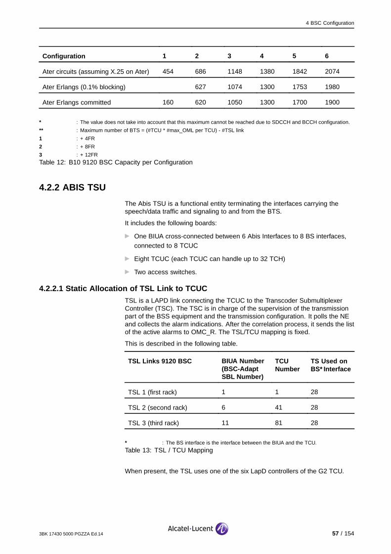
4 BSC Configuration
Configuration 1 2 3 4 5 6
Ater circuits (assuming X.25 on Ater) 454 686 1148 1380 1842 2074
Ater Erlangs (0.1% blocking) 627 1074 1300 1753 1980
Ater Erlangs committed 160 620 1050 1300 1700 1900
* : The value does not take into account that this maximum cannot be reached due to SDCCH and BCCH configuration.
** : Maximum number of BTS = (#TCU * #max_OML per TCU) - #TSL link
1 : + 4FR
2 : + 8FR
3 : + 12FR
Table 12: B10 9120 BSC Capacity per Configuration
4.2.2 ABIS TSU
The Abis TSU is a functional entity terminating the interfaces carrying thespeech/data traffic and signaling to and from the BTS.
It includes the following boards:
One BIUA cross-connected between 6 Abis Interfaces to 8 BS interfaces,connected to 8 TCUC
Eight TCUC (each TCUC can handle up to 32 TCH)
Two access switches.
4.2.2.1 Static Allocation of TSL Link to TCUCTSL is a LAPD link connecting the TCUC to the Transcoder SubmultiplexerController (TSC). The TSC is in charge of the supervision of the transmissionpart of the BSS equipment and the transmission configuration. It polls the NEand collects the alarm indications. After the correlation process, it sends the listof the active alarms to OMC_R. The TSL/TCU mapping is fixed.
This is described in the following table.
TSL Links 9120 BSC BIUA Number(BSC-AdaptSBL Number)
TCUNumber
TS Used onBS* Interface
TSL 1 (first rack) 1 1 28
TSL 2 (second rack) 6 41 28
TSL 3 (third rack) 11 81 28
* : The BS interface is the interface between the BIUA and the TCU.
Table 13: TSL / TCU Mapping
When present, the TSL uses one of the six LapD controllers of the G2 TCU.
3BK 17430 5000 PGZZA Ed.14 57 / 154

4 BSC Configuration
4.2.2.2 Static Allocation of TRX and BTS to TCUCEach TCUC can handle:
A maximum of six LAPD links
A maximum of four RSL FR or two RSL DR
A maximum of three OML.
This is shown in the following table.
TRX OML TSL
4 FR 2
4 FR 1 1
3 FR 3
2 FR 2 1
2 DR 2 1
Table 14: Configuration Example
The following rules apply:
In the case of Signaling Multiplexing:
For 16K static multiplexing, all RSLs of a given 64 Kbit/s Abis timeslot
must be handled by the same TCUC
For statistical multiplexing, all multiplexed RSL and OML are processed
on the same TCU.
Mixing signaling multiplexing and non-multiplexed signaling on the sameTCU is allowed
Each TCUC can handle 32 Traffic channels, which allows:
Full rate TRXs
Two dual rate TRXs.
Each TCUC can handle eight extra Abis timeslots, which reduces the
number of TRE per TCUC
The operator can choose the multiplexing scheme of the BTS and therate type of the TRX.
Each Abis TSU (BIUA) can handle six Abis links, which allows:
A maximum three ring configuration (looped multidrop)
A maximum six chain configuration (open multidrop or star configuration).
Abis TSU can mix FR or DR TRXs
Each Abis TSU holds eight TCUC
58 / 154 3BK 17430 5000 PGZZA Ed.14

4 BSC Configuration
First Abis TSU for the first rack and the second Abis TSU of second andthird rack can only support up to 14 DR TRE if first TCU of the TSU is
presently configured as FR TCU.
First Abis TSU for the first rack and the second Abis TSU of second and
third rack can only support up to 28 FR TRE if first TCU of the TSU is
presently configured as DR TCU.
Modification of the configuration FR/DR of the first TCU is not supported
from the OMC.
In the case of a closed multidrop (Ring), both ends must be connected tothe same Abis TSU:
It is advisable to use Abis Ports 1, 3, 5 first for an open multidrop and, in the
case of a closed multidrop, use the Abis ports 1&2, 3&4, 5&6
The Abis TSU can handle up to 8 * 4 = 32 FR TRXs.
TCU
BIU
Abis
switch
Abis TSU
TCU
TCU
TCU
TCU
TCU
TCU
TCU
Abis
Abis
Abis
Abis
Abis
4.2.2.3 HR FlexibilityCurrently, GSM network operators see the HR as a way of extending thecapacity of the network without any additional hardware deployment (i.e.without any extra significant cost).
The gradual introduction of HR allows the operator to define each individualTRE as full rate or dual rate. This allows control of the HR ratio on a per cellbasis. Due to the TRE/TCU mapping algorithm where TRE and TCU must beof the same type (full rate, dual rate), mapping is not possible when there isno TCU at all or when the TCU which can be available is already mapped toTRE whose type is different.
The TCUs of a TSU are allocated, by the 9120 BSC, to support FR or DR TREsaccording to the mapping algorithm:
The 2 types of TRE are mapped on compatible TCUs with a maximum of 4FR TREs per FR TCU and 2 DR TREs per DR TCU
The BSC allocates free TCUs as FR or DR TCU, according to requirements
3BK 17430 5000 PGZZA Ed.14 59 / 154

4 BSC Configuration
In each rack the TCUC which carries the TSL link cannot be modifiedfrom full rate to half rate, or vice versa, depending on the TCUC original
configuration.
60 / 154 3BK 17430 5000 PGZZA Ed.14

4 BSC Configuration
Abis Signaling TS Allocation
HR flexibility uses the 64 Kbit/s statistic OML/RSL multiplexing rule or nomultiplexing mode.
The statistical multiplexing scheme (64/4, 64/2, 64/1) is not defined by theoperator, but the operator can select the expected level of signaling load (highor normal) per BTS or per sector according to:
Normal signaling load
4:1 is the maximum multiplexing scheme allowed for FR TRX
2:1 is the maximum multiplexing scheme allowed for DR TRX.
High signaling load
2:1 is the maximum multiplexing scheme allowed for FR TRX
1:1 is the maximum multiplexing scheme allowed for DR TRX.
The BSC is responsible for selecting the multiplexing scheme compatible withthe signaling load and the TRE type.
4.2.3 Ater TSU
The Ater TSU is a functional entity terminating the interfaces to and from thetranscoder and/or the MFS.
It includes the following boards:
Two ASMB, providing multiplexing 16 Kbit/s from 4 tributaries to 1 highway
Eight DTCC
Two access switches.
4.2.3.1 DTC RulesThe following rules apply:
Any of the first DTCs in each group of four supporting an Atermux interface(among the 16 first Ater Mux) can terminate an SS7 signaling link if the
Ater Mux is CS
There are six potential BSC synchronization sources (one from eachAtermux in the first rack). If the Atermux is used, then the first DTC attached
to that ASMB recovers a synchronization reference signal and sends thisto the BSC central clock
DTCC can be dedicated for SS7-MTP (supporting a physical SS7 link), GSL
(supporting a physical GSL), BSSAP/GPRSAP (higher layers of SS7 andGSL) or TCHRM (TCH allocation)
One DTCC TCH-RM pair can handle up to 60 cells and the number of
TRX per TCH-RM is limited to 90.
3BK 17430 5000 PGZZA Ed.14 61 / 154

4 BSC Configuration
4.2.3.2 DTC Architecture and FunctionsThe DTC processors are configured by default to perform one of three mainfunctions:
TCH-RM
BSSAP/GPRSAP
GSL
MTP-SS7.
The following table shows the default mapping on the DTC SBL number.
BSC Configuration
1 2 3 4 5 6
TCH-RM 3-4, 11-12 27-28, 35-36 51-52, 59-60
BSSAP/ GPRSAP 2, 6-8, 10,14-16
18-20,22-24
26, 30-32,34, 38-40
42-44,46-48
50, 54-56,58, 62-64
65-72
SS7-MTP 1, 5, 9, 13 17,21 25, 29, 33,37
41, 45 49, 53, 57,61
GSL 2, 6, 10, 14 18, 22 26, 30,34,38
42, 46 50, 54, 58,62
Table 15: DTC Configuration and SBL Number
Rules and Dimensioning
The following rules apply:
Up to 16 DTC are allowed with the SS7 link, on first 16 AterMux
For GPRS, the second DTC in each group of four (e.g. DTCs 2, 6 etc.) canbe configured to handle GSLs on TS28
The second DTC on the first 2 Atermux can support X.25 on TS31.
4.2.4 TSC Function
The 9120 BSC is directly in charge of the configuration of the TSC. In terms ofsoftware management, the TSC is treated like any other BSC processor (e.g.DTC). The TSC software is an integral part of the BSC software package.
The TSC data base update mechanisms must follow the principles of the BTSdata base updates (i.e. the TSC is configured by data coming from BSC atstart up, and whenever the BSS configuration has changed something whichis of interest for the TSC).
62 / 154 3BK 17430 5000 PGZZA Ed.14

4 BSC Configuration
4.3 9130 BSC Evolution
4.3.1 9130 BSC Evolution Architecture
The following figure shows the BSC hardware architecture on an ATCA platform.
SSW
(duplicated)
Rad
io N
etw
ork
lin
ks
External Ethernet Links
LIU Shelf
(21 slots)
E1
CCP y
TPr
TP
Mux
LIU1
LIU n
ATCA Shelf (14 slots)
CCP
OMCPw
OMCPr
r : Redundancy
W : Working
N and y : Network Element capacity
Figure 7: 9130 BSC Evolution Hardware Architecture
3BK 17430 5000 PGZZA Ed.14 63 / 154

4 BSC Configuration
The following table describes the 9130 BSC Evolution functional blocks andboards.
Name Functional block mapped on board Existing function for BSC
SSW: Gigabit Ethernetswitch (in ATCA shelf)
Allows exchanges between all theelements of the platform and externalIP/Ethernet equipment:
Performs Gigabit Ethernet switching
at the shelf level
Performs powerful monitoring forthe user plane and control plane
(Gigabit Ethernet on front panel)
Ensures daisy chain with other
shelves via two 1 Gigabit Ethernet
ports (only one is used)
Ensures multicast function
Allows several external Ethernet
10/100/1000 Base T connections:OMC-R, CBC, LCS, Debug
Implements 12 non blocking
1Gigabit Ethernet links viabackplane connections
The SSW board and all the connectionsto the switch are duplicated to overcomeboard or connection failures.
OMC-R physical interface
CBC physical interface
Monitoring
NEM terminal connection
OMCP: O&M ControlProcessing board (inATCA shelf)
Is based on ATCA technologyequipped with a permanent storagedevice. It manages the platform assystem manager, and manages O&Mapplications.
OMCP boards operate in active-standbymode following the 1+1 redundancymodel.
O&M logical interface to the Operationand Maintenance Center (OMC-R)
VCPR: S-CPR & O-CPR software +TCH/RM
TSC software
CCP: ControlProcessing board(in ATCA shelf)
Is based on ATCA technology used forcall control functions. Identical to theOMCP board but without a hard disk.
CCP boards operate in an N + 1redundancy model. N is the numberof active boards ready to handle trafficand one standby CCP board is alwaysavailable to take over the traffic of failedboard.
VTCU: TCU software
VDTC: DTC software
64 / 154 3BK 17430 5000 PGZZA Ed.14

4 BSC Configuration
Name Functional block mapped on board Existing function for BSC
TP GSM: TransmissionProcessing board (inATCA shelf)
Provides telecom transmission /transport interfaces to the ATCAplatform.
Gigabit Ethernet switchOn-board local switch(separates/aggregates nE1oEtraffic and IP control traffic).
NE1oETransports n x E1 frames in Ethernetpayloads
Multiplexes/demultiplexes up to 252
E1Multiplexes/demultiplexes up to 252E1 from/to the Gigabit EthernetInterface (NE1oE).
TDM switch8 kbit/s synchronous switching witha total bandwidth of 284 * 2 Mbits(252 external links + 32 internal linkstoward HDLC, SS7, Q1 and R/Wbits controllers).
Handles low layers of GSM protocolsLAP-D over HDLC, ML-PPP overHDLC, SS7, Q1 (= QMUX) and R/Wbits.
Two TPGSM boards are available.They operate in active-standby modefollowing 1+1 redundancy model.
HDLC termination
SS7 termination
NE1oE
Q1
Ring control
LIU boards (in LIUshelf)
Interface for E1 links These links correspond to the userplane interfaces.
MUX board (in LIUshelf)
Concentrates and converts E1 inEthernet and vice versa.
NE1oE
LIU Shelf Multiplex/demultiplex which crossconnects all E1 external links to/froma NE multiplexed links (n E1 overEthernet) at TP and GP board.
It is equipped with 2 x Mux board andn LIU boards.
E1 physical termination
NE1oE
ATCA Shelf See above.
3BK 17430 5000 PGZZA Ed.14 65 / 154

4 BSC Configuration
4.3.2 Configurations
For the 9130 BSC Evolution, E1 termination ports are generic and areconfigured to "Abis", "Ater" or "not used". Consequently Abis or Ater terminationports may be not contiguous. Abis-Hway-TP are numbered from the first E1termination port to the last one. The numbering of Abis-Hway-TP remainswithout holes, even if they are mapped on discontinuous E1 termination ports.It is the same for the Ater-Hway-TP.
In fact, the engineering rules lead to specialize the 16 LIU boards:
[1, 11] Abis
[12, 16] Ater
Only three LIU boards (14, 15, 16) are used for Ater (12 & 13 are reserved forfuture usage).
As there are 16 E1 per LIU board (i.e. 256 E1 with configuration type 3):
11x 16=176 E1 Abis HW-TP
3x16=48 E1 Ater HW-TP
Note that TP-GSM board can only manage 252 E1 so 4 E1 cannot be used.
Ater can be:
Ater CS, supporting only CS, direct link BSC-TC
Ater PS, supporting only PS (dedicated, not passing through TC),supporting CS and PS (mixed, passing through TC).
66 / 154 3BK 17430 5000 PGZZA Ed.14

4 BSC Configuration
The following figure shows the 600 TRX LIU Shelf connections assignment:
Figure 8: 1000 TRX LIU Shelf Connections Assignment
3BK 17430 5000 PGZZA Ed.14 67 / 154
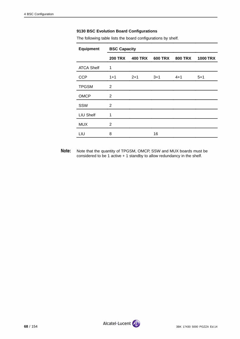
4 BSC Configuration
9130 BSC Evolution Board Configurations
The following table lists the board configurations by shelf.
BSC CapacityEquipment
200 TRX 400 TRX 600 TRX 800 TRX 1000 TRX
ATCA Shelf 1
CCP 1+1 2+1 3+1 4+1 5+1
TPGSM 2
OMCP 2
SSW 2
LIU Shelf 1
MUX 2
LIU 8 16
Note: Note that the quantity of TPGSM, OMCP, SSW and MUX boards must beconsidered to be 1 active + 1 standby to allow redundancy in the shelf.
68 / 154 3BK 17430 5000 PGZZA Ed.14

4 BSC Configuration
4.3.3 9130 Capabilities
The following table shows the 9130 BSC Evolution capabilities.
Configuration Type 1 2 3 4 5
Nb TRX 200 400 600 800 1000
Nb Cell 200 400 500 500 500
Nb BTS 150 255 255 255 255
Nb SS7 links 8 16 16 16 16
Nb CICs 1024 2068 3112
DR TRE 200 400 600 800 1000
Capacity
FR TRE 200 400 600 800 1000
Abis 96 96 176 176 176
Ater CS 10 20 30 40 48
Nb of E1
Ater PS 6 12 18 24 28
Nb TCU 50 100 150 200 250
Nb DTC CS 40 80 120 160 200
Nb VCE CCP
Nb DTC PS 24 48 72 96 120
Nb TCH-RM pairs 1 1 1 1 1
Nb CPR pairs 2 2 2 2 2
Nb VCE OMCP
Nb TSC pairs 8 8 8 8 8
Nb VCE per CCP 114 114 114 114 114Nb VCE per board
Nb VCE/OMCP 11 11 11 11 11
The 9130 BSC Evolution can reach 2600 Erlangs.
3BK 17430 5000 PGZZA Ed.14 69 / 154

4 BSC Configuration
4.3.4 Rules and Assumptions
The following characteristics apply for the 9130 BSC:
The capacity of the 9130 BSC is extended to 1000 TRX by adding two CCP
boards in the ATCA shelf
The TP GSM board supports the traffic of 1000 TRXs, depending on the
generation
The maximum number of TREs mapped to a CCP is independent onwhether the TRE is HR or DR
It is possible to map up to four TREs per VTCU, i.e. up to 200 TREs per CCP
The maximum number of TCH a CCP can handle is limited to 1100
The capacity is extended to 500 cells for the 9130 BSC
The number of adjacencies supported per 9130 BSC is 10300
The GP board (9130 MFS) are configured to support 1000 TRX contexts
and 8000 mobiles contexts
The increase of TRX capacity has also impact on the number of extra Abistimeslots that are supported by the 9130 BSC in that it is increased up to
2000. This increase leads to two extra Abis timeslots available per TRX.
The TCU/RSL mapping (Removal of HR impact on BSC connectivity)allows the mapping of four RSL on each TCU, regardless of their speech
rate. Consequently, it is always possible to configure 200 TRX on a CCP.This algorithm must map (as much as possible) all TRE of a BTS on the
same CCP.
There is a maximum of 16 LSL or two HSL objects configured per BSC
Atermux 59 and 60 could only be used for HSL or packet
The number of LAPD link configured will still be 250 ( 50 VTCU/CCP * 5)
BTS G1 Mark II is not supported
Qmux is not supported in TS0
The number of HDLC channels is limited, requiring the usage of statisticmultiplexing in the large configurations
On the BSC Evolution, it is possible to connect an external alarm box. Theelectrical convention for these alarms must be unique for a certain alarm box
The O&M connection is possible via IP or via several TS on the A interface
The external alarms can be collected by an External Alarm Box (EAB); refer
to the External Alarm Box Installation and Commissioning Manual formore information.
70 / 154 3BK 17430 5000 PGZZA Ed.14

4 BSC Configuration
4.4 Common Functions
4.4.1 SDCCH Allocation
4.4.1.1 OverviewThe dynamic SDCCH allocation feature is a mechanism which providesautomatic (the optimal number of) SDCCH in a cell, which translates as a set ofdynamic SDCCH/8 TS, used for TCH traffic or for SDCCH traffic, depending onactual traffic. SDCCH management is handled by the operator in RNUSM. Itis also possible to customize the SDCCH templates by choosing from a listof 10 patterns managed by the OMC-R to define SDCCH configurations.16 sub-templates are associated with each template, corresponding to thepossible number of TRXs in a cell, because no algorithm can be defined toevaluate the number of SDCCH depending on the number of TRX in a cell.
4.4.1.2 TerminologyA static SDCCH/x TS refers to one physical TS on the Air interface containing xSDCCH sub-channels (x = 3, or 4, or 7, or 8, depending whether the TS isSDCCH/3, or SDCCH/4, or SDCCH/7, or SDCCH/8).
4.4.1.3 General PrinciplesIn terms of configuration:
Dynamic SDCCH allocation only deals with SDCCH/8 TS. It is not necessary
to add or suppress a SDCCH/3, or a SDCCH/4, or a SDCCH/7 TS
In the case of manual configuration (not assisted), the operator configuresthe static and dynamic SDCCH TS for the cell but cannot reuse the
configuration for other cells
CBCH is configured on a static SDCCH/8 or SDCCH/4 TS
The operator must configure at least one static SDCCH/8 or SDCCH/4
TS on BCCH TRX in a cell
The total number of SDCCH sub-channels configured on static or dynamicSDCCH TS or on a BCCH/CCCH TS (CCCH combined case) must not
exceed 24 sub-channels per TRX
The maximum number of SDCCH per cell must be verified to ensure thatthe number of configured SDCCH, dynamic and static, for a cell must not
exceed the defined maximum of 88.
3BK 17430 5000 PGZZA Ed.14 71 / 154

4 BSC Configuration
In terms of usage:
A dynamic SDCCH TS carry only CS traffic.
BTS with DRFU do not support SDCCH dynamic allocation
In multiband and concentric cells, only the TRX, which belong to the outerzone, can support dynamic and static SDCCH
Static SDCCH/8 TS cannot be used as TCH
Dynamic SDCCH/8 TS are allocated for SDCCH only if all the static
SDCCH/8 TS are busy (i.e. all its sub-channels are busy)
It is not possible to drop a TCH call to free a TS for SDCCH/8 allocation
A TCH call is preferably not allocated in the area of the dynamic SDCCH/8
TS
Combined SDCCHs (SDCCH/4 + BCCH) are always static
In order to avoid incoherent allocation strategies between the SDCCH
and PDCH, a dynamic SDCCH/8 TS cannot be a PDCH (it can not carryGPRS traffic)
In cells with E-GSM, only the TRX, which belong to the P-GSM band, can
support dynamic and static SDCCH
Note: In the case of a fault on an RSL, there is recovery of dynamic SDCCH.
72 / 154 3BK 17430 5000 PGZZA Ed.14
4 BSC Configuration
4.4.2 Multiple CCCH
The multiple CCCH feature allows the operator to use only one additionalCCCH, so that timeslots TS0 and TS2 can be used. The operator decides toconfigure either one or two TS for mCCCH. The multiple CCCH feature can letlarge cells (even with 12 FR TRX) support more Erlangs, from 100 Erlangsonwards with the 9100 Traffic Model.
4.4.2.1 TRX Channel Configuration RulesThe following configuration rules apply:
It is not allowed to active a second CCCH when the CCCH in the cell
is combined with SDCCH
It is assumed that one CCCH equals to SDCCH/8 in terms of RSL load andprocessor load imposed by the signalling by a CCCH
The maximum number of SDCCH TS in the cell is:
11 if there is one CCCH
22 if there is two CCCH
Only one SDCCH can be configured in TS1 on the Beacon TRX when two
CCCH are configured in TS0 and TS2
TS0: FCCH + SCH + BCCH + CCCH
TS1/TS3: SDCCH + SACCH on TS1/TS3/TS4/TS5/TS6/TS7 or SDCCH
+ SACCH + CBCH
TS2: BCCH + CCCH
Multiple CCCH is not supported in Extended Cell and VGCS
CCH must be configured on TS2 of BCCH TRX
When BCCH is combined with SDCCH, CCH cannot be configured
In BCCH TRX, when BCC and CCH are configured on TS0 and TS2, only
one Static SDCCH is allowed to config on the others TS
In the cell with both BCC and CCH, the maximum number of SDCCH TSis extended to 22
In BCCH TRX, when CCH is configured, only one Static SDCCH is allowed
CBC and CBH are forbidden when mCCCH is configured on BCCH TRX
DYN SDCCH is forbidden on BCCH TRX when mCCCH is configuredon BCCH TRX
CCH is the new channel type for BCCH + CCCH.
BCC is the channel type for FCCH + SCH + BCCH + CCCH.
3BK 17430 5000 PGZZA Ed.14 73 / 154

4 BSC Configuration
4.4.2.2 TRX LimitationsThe following TRE hardware limitations exist:
G3 Maximum number of CCCH + SDCCH = 3
In TDM mode: max number of SDCCH subchannel = 24
In IP mode: max number of SDCCH subchannel = 16*
G4: maximum number of CCCH + SDCCH = 4
G5 (TWIN TRA): maximum number of CCCH + SDCCH = 4
All Platforms: Maximum number of SDCCH channels = 24
The beacon TRX supports all CCCH slots.
The maximum number of signalling channels follows this rule:
With CCCH on TS0:
G3: Maximum number of TS per TRX = 2 SDCCH + 1 CCCH
G4 and G5: Maximum number of TS per TRX = 3 SDCCH + 1 CCCH
With the additional CCCH on TS2 A TRX(G3, G4 and G5) must support:
FCCH + SCH + BCCH+CCCH on TS0
SDCCH on TS1/TS3/TS4/TS5/TS6/TS7
BCCH+ CCCH on TS2
4.4.2.3 TRX/RSL/TCU Mapping RulesIn order to avoid the load on TCU in G2BSC, 32 SDCCH subchannel limitationper TCU is maintained. Since one CCCH equivalent to one SDCCH (8 SDCCHsubchannel), total number of signalling channels on one TCU should be lessor equal to four: N_TS_CCCH + N_TS_SDCCH <=4. Note that this ruleapplies only to the 9120 BSC. For 9130 BSC, there is no restriction (unlessthere are load issues on the BTS). The limitation on the OMC-R is a maximumthree SDCCH per TRX.
4.4.3 Common Behavior
The 9120 BSC and 9130 BSC share the following behavior modes:
No change in the logical model of the BSC
No change in the radio configuration mechanisms
Same set of radio parameters
No changes in PM mechanisms
Same set of PM counters/indicators as the 9120 BSC.
74 / 154 3BK 17430 5000 PGZZA Ed.14

4 BSC Configuration
4.5 Delta 9130 BSC Evolution versus 9120 BSCThe 9130 BSC Evolution differs from the standard BSC as follows:
Compared to previous generation BSC, the ATCA PF does not provide X.21
interfaces. An X25 over IP link is used for CBC.
TSU is removed
No more SDCCH limitation per TCU (32)
Remote inventory (like for other NEs)
Replace FTAM with FTP
Time/date management by ntp
Ater programming - new strategy
BSS files management - ftp browser
SNMP used for overload
Abis/Ater fixed mapping to LIU boards
Support of HSL
Remove HR impact
The 9130 BSC Evolution can be used as clock synchronization source for
AS800, DS10 or 9130 MFS
The TSU concept no longer exists
Free allocation of any RSL/OML to any TCU, thus allowing the full TREcapacity and avoiding any internal BSC moves
No need of TCU capacity to support the extra Abis TS. Edge traffic can besupported even when the BSC has the maximum of TRE.
3BK 17430 5000 PGZZA Ed.14 75 / 154

4 BSC Configuration
4.6 SBLs Mapping on Hardware Modules in 9130 BSC Evolutionversus 9120 BSC
The following figure shows the different kinds of SBLs (with their hardwaremodule mapping) shown at the interface between the 9120 BSC and the BTSsand at the interface between the BTSs. The internal links between TCU andBIU are mapped on SBLs having "BSC-ADAPT" as SBL type.
BTS Side
BIUA
BSC −ADAPT
−BTS ADAPT
TCU
TCU
ABIS −HWAY −TP(Unit type=BSC)
BIE
ABIS −HWAY −TP(Unit type=BTS)
BIE
BSC Side
−BTS ADAPT
The following figure shows the different kinds of SBLs (with their hardwaremodule mapping) shown at the interface between the 9130 BSC Evolution andthe BTSs and at the interface between the BTSs. For the 9130 BSC Evolution,the SBL BSC-ADAPT is removed.
BTS Site Mx−BSC Site
TP
GG SSM
TP− HW
(Unit type=BSC)
ECU
ETU
LIU
MUX ABIS −HWAY −TP
(Unit type=BSC)
ABIS −HWAY −TP
(Unit type=BTS)
−BTS ADAP T
BIE
ABIS −HWAY −TP
(Unit type=BTS)
−BTS ADAPT
BIE
ABIS −HWAY −TP
(Unit type=BTS)
ABIS −HWAY −TP
(Unit type=BTS)
SSW−HW
(Unit type=BSC)
SSW
Note: BIUA connectors in the 9120 BSC correspond to E1 termination ports inthe 9130 BSC Evolution.
76 / 154 3BK 17430 5000 PGZZA Ed.14

5 TC Configuration
5 TC Configuration
This section describes the transcoder, and corresponding features andfunctions.
3BK 17430 5000 PGZZA Ed.14 77 / 154
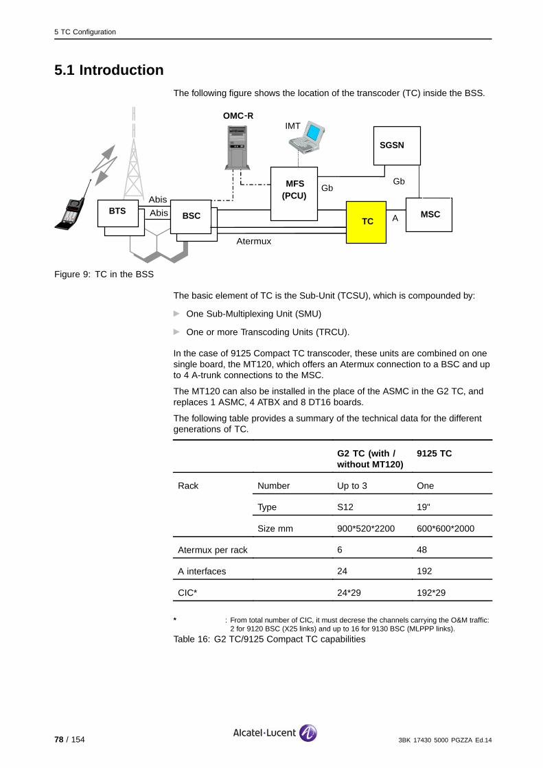
5 TC Configuration
5.1 IntroductionThe following figure shows the location of the transcoder (TC) inside the BSS.
BTS
Abis
Abis
Atermux
A
Gb
OMC−R
IMT
SGSN
BSC TC
MFS
(PCU)
MSC
Gb
Figure 9: TC in the BSS
The basic element of TC is the Sub-Unit (TCSU), which is compounded by:
One Sub-Multiplexing Unit (SMU)
One or more Transcoding Units (TRCU).
In the case of 9125 Compact TC transcoder, these units are combined on onesingle board, the MT120, which offers an Atermux connection to a BSC and upto 4 A-trunk connections to the MSC.
The MT120 can also be installed in the place of the ASMC in the G2 TC, andreplaces 1 ASMC, 4 ATBX and 8 DT16 boards.
The following table provides a summary of the technical data for the differentgenerations of TC.
G2 TC (with /without MT120)
9125 TC
Number Up to 3 One
Type S12 19"
Rack
Size mm 900*520*2200 600*600*2000
Atermux per rack 6 48
A interfaces 24 192
CIC* 24*29 192*29
* : From total number of CIC, it must decrese the channels carrying the O&M traffic:2 for 9120 BSC (X25 links) and up to 16 for 9130 BSC (MLPPP links).
Table 16: G2 TC/9125 Compact TC capabilities
78 / 154 3BK 17430 5000 PGZZA Ed.14

5 TC Configuration
The following figure shows an example of sharing of 9125 TC by several BSC.
AterMuxBSC1rack1
AterMuxBSC1rack2
AterMuxBSC3rack3
AterMuxBSC4rack1
AterMuxBSC1rack3
AterMuxBSC2rack1
AterMuxBSC4rack2
AterMuxBSC5rack1
AterMuxBSC2rack2
AterMuxBSC2rack3
AterMuxBSC5rack2
AterMuxBSC6rack1
AterMuxBSC3rack1
AterMuxBSC3rack2
AterMuxBSC6rack2
AterMuxBSC7rack1
AterMuxBSC7rack2
TC RACK1 TC RACK2 TC RACK3used first to extend BSC7
3BK 17430 5000 PGZZA Ed.14 79 / 154

5 TC Configuration
5.2 G2 TC
5.2.1 Architecture
There are 2 types of G2 TC:
G2 TC equipped with ASMC and TRCU
G2 TC equipped with ASMC/TRCU + MT120 boards (in the case ofan extension).
The G2 TC architecture is linked to the 9120 BSC architecture (that is, theAter TSU). A G2 TC rack is compounded by 6 Sub-multiplexing Units (SU)with a granularity of 1 SU = 1 ASMC + 4 TRCU.
The ASMC terminates one Atermux on the TC side
The TRCU is Transcoder Unit (TCU) compounded by 1 ATBX and 2 DT16.
One SU terminates one Atermux on the TC side in front of:
One ASMB board on the 9120 BSC side
One LIU board on the 9130 BSC side
4 A Interfaces on the MSC side.
5.2.2 Rules and Dimensioning
The following rules apply:
The G2 TC equipped with MT120 boards adheres to the following rules:
It must contain at least two (ASMC + four TRCUs)
When a new TC rack is needed, the extension is performed by a 9125Compact TC rack.
One G2-TC Full Rack can be installed in front of the 9120 BSC (one full
G2-TC rack means Conf 2: 6 Atermux. as two SU are required in frontof one Ater TSU)
The maximum number of racks is three (i.e. 6*3=18 Atermux).
80 / 154 3BK 17430 5000 PGZZA Ed.14

5 TC Configuration
Taking into account the above rules for G2 TC equipped with MT120, theconfiguration rules described in the following table apply for this rack.
Configuration Per Rack Extension /Reduction
Physical/Logical
Minimum Maximum Minimum
G2 TC 2 Atermux 6 Atermux One Atermux
SU 2 6 1
ASMC 2 6 1
TRCU SM 4:1 4 24 4
MT120 - 4 1
Table 17: G2 TC Configurations
Rules:
When creating one logical Atermux, the new granularity of hardware addedis: n or one ASMC + 4xATBX + (4x2 DT16)
Before introducing MT120 in a G2 TC, the ASMC must be completed with all
required DT16 (to remove holes in the ASMC).
3BK 17430 5000 PGZZA Ed.14 81 / 154
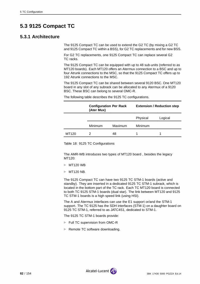
5 TC Configuration
5.3 9125 Compact TC
5.3.1 Architecture
The 9125 Compact TC can be used to extend the G2 TC (by mixing a G2 TCand 9125 Compact TC within a BSS), for G2 TC replacements and for new BSS.
For G2 TC replacements, one 9125 Compact TC can replace several G2TC racks.
The 9125 Compact TC can be equipped with up to 48 sub-units (referred to asMT120 boards). Each MT120 offers an Atermux connection to a BSC and up tofour Atrunk connections to the MSC, so that the 9125 Compact TC offers up to192 Atrunk connections to the MSC.
The 9125 Compact TC can be shared between several 9120 BSC. One MT120board in any slot of any subrack can be allocated to any Atermux of a 9120BSC. These BSC can belong to several OMC-R.
The following table describes the 9125 TC configurations.
Configuration Per Rack(Ater Mux)
Extension / Reduction step
Physical Logical
Minimum Maximum Minimum
MT120 2 48 1 1
Table 18: 9125 TC Configurations
The AMR-WB introduces two types of MT120 board , besides the legacyMT120:
MT120 WB
MT120 NB.
The 9125 Compact TC can have two 9125 TC STM-1 boards (active andstandby). They are inserted in a dedicated 9125 TC STM-1 subrack, which islocated in the bottom part of the TC rack. Each TC MT120 board is connectedto both TC 9125 STM-1 boards (dual star). The link between MT120 and 9125TC STM-1 boards is a high speed link (using HSI).
The A and Atermux interfaces can use the E1 support or/and the STM-1support. The TC 9125 has the SDH interfaces (STM-1) on a daughter board on9125 TC STM-1, referred to as JATC4S1, dedicated to STM-1.
The 9125 TC STM-1 boards provide:
Full TC supervision from OMC-R
Remote TC software downloading.
82 / 154 3BK 17430 5000 PGZZA Ed.14
5 TC Configuration
5.3.2 Rules and Dimensioning
For Qmux connectivity, all the TC boards connected to one BSC cluster mustbelong to the same TC rack.
For redundancy purposes, a BSC must be connected to a 9125 Compact TCvia a minimum two Atermux. For example:
24 BSCs with two Atermux can be connected to a 9125 Compact TC rack
Six BSCs with eight Atermux can be connected to a 9125 Compact TC rack.
Extension
A Qmux cluster is a group of up to six MT120 which ensure the Qmuxsupervision of the boards with the TSC/VTSC of the related BSC. These MT120boards must be always in the same 9125 Compact TC rack.
A Qmux cluster corresponds to one 9120 BSC rack, or to group of six Ater Muxin 9130 BSC (1..6, 7..12,.).
The notion of Qmux clusters is important during the extension of Atermux in aBSC rack, as it can induce modification of the initial configuration.
The maximum number of MT120 boards is equal to 48.
In case of 9130 Evolium BSC:
Atermux 1 to 30 are CS
Atermux 31 to 58 are dedicated to PS
Atermux 59, 60 are PS or HSL
For example, if the extension suited is 32 CS Atermux with 32 MT120, it is
needed to use Atermux 61 and 62 (or higher 63 64...). The ’New ConfigTC’ in BSC Terminal must be filled in according to the highest number of
the Ater Mux of the BSC. In this case 61and 62.
Different extensions are possible:
Extension of Atermux in a BSCIn this case, the Qmux cluster is increased. Recabling of all of the Atermuxof a cluster into a new 9125 Compact TC rack is necessary if there are nomore free slots in the 9125 Compact TC.
G2 TC extensionOnce the G2 TC rack maximum capacity (six Ater) is reached, the BSCextension requires TC capacity. In this case, the 9125 Compact TCrack is required as the G2 TC rack extension (G2 TC rack is kept). The9125 Compact TC rack can be shared afterwards between different BSCextensions. An 9125 Compact TC rack can also be added even if the G2 TCrack is not completely filled (in the case of GPRS holes).
New rack of a 9120 BSC by extension of Atermux capacityDepending on the free slot capacity in the 9125 Compact TC, a new 9125Compact TC may be required.
New 9130 BSC configuration
New BSCDepending on the free slot capacity in the 9125 Compact TC, a new 9125Compact TC may be required.
3BK 17430 5000 PGZZA Ed.14 83 / 154
5 TC Configuration
STM-1 interfaces
The STM-1 interfaces are numbered from 1 to 4, instead of 240 E1 links
The TC can be pure STM-1, pure E1 or mixed
One STM-1 can carry up to 63 E1 (on VC-12)
One STM-1 port can be shared between A and Ater interfaces.
BTS
There are a maximum 1024 BTS allowed to be served by a TC rackas the primary TC
The number of BTS served as secondary TC is unlimited.
84 / 154 3BK 17430 5000 PGZZA Ed.14

6 MFS Configuration
6 MFS Configuration
This section describes the MFS, and corresponding features and functions.
3BK 17430 5000 PGZZA Ed.14 85 / 154

6 MFS Configuration
6.1 MFS in BSSThe MFS enables GPRS in the network. The following figure shows the locationof the MFS in the network.
BTS
Abis
Abis
Atermux
A
Gb
OMC −R
IMT
SGSN
BSC TC
MFS(PCU)
MSC
Gb
Figure 10: MFS in the Network
6.2 9135 MFS
6.2.1 MFS Architecture
The Multi-BSS Fast packet Server (MFS) comprises the sub-systems:
The Control Sub-System (CSS), which is built from two DECAlpha AS800 or
COMPAQ DS10 servers, one of which is active and one of which is standby(referred to as the Control Station)
Telecom Sub-System (TSS), which is a set of GPU and JBETI boards
Hub subsystem, which consists of duplicated 100 Mbit/s Ethernet networks
for interconnection. In the case of GB over IP, there is no hub.
86 / 154 3BK 17430 5000 PGZZA Ed.14

6 MFS Configuration
The following figure shows the MFS architecture.
/HUBFrom / to BSC
and TC
AtermuxInterfaces
AtermuxInterfaces
AtermuxInterfaces
Gb Interface
Gb Interface
Gb Interface
Control Station
GPU
GPU
GPUE
ther
net L
AN
IP / Ethernetto OMCR
From / toSGSN
Figure 11: 9135 MFS Architecture
An MFS includes at least one subrack equipped with:
16 (maximum) GPU boards (minimum is 2, including 1 spare)
Two redundant Ethernet Hubs
Two redundant Control Stations
One IOLAN with 8 ports.
6.2.1.1 GPRS Processing UnitThe GPRS Processing Unit (GPU) board is part of the MFS, and is linked toone BSC.
The GPU supports the Packet Control Unit (PCU), as defined by GSM. ThePCU allows the BSS to access the GPRS service to SGSN.
The PCU is split into two parts:
The Packet Management Unit (PMU), which handles asynchronous
functions and control functions
The Packet Traffic Unit (PTU), which handles synchronous radio functions
and data transfer functions.
There are a maximum of 16 PCM links per GPU board. The use of these PCMlinks is not dedicated, and each interface can be connected to BSS or NSSentities. The supported interfaces are:
Mixed Ater transport TCH from the BTS to existing the TC on the BSC
side and TC side
Gb connects the MFS directly to SGSN, through the Frame Relay Network
or through the MSC. The capacity required depends on GCH in Atermux.
The GPU AB and GPU AC supports 264 cells.
LCS in the GPU also implements the SMLC function. For more information,refer to LCS in BSS (Section 6.4.2).
3BK 17430 5000 PGZZA Ed.14 87 / 154

6 MFS Configuration
6.2.1.2 Multiple GPU per BSSIn order to increase the GPRS capacity of the BSS in terms of the number ofPDCH, it is possible to connect several GPUs boards to the BSC to support thePCU function.
The maximum number of GPUs to be connected to a BSC depends on theconnection capacity of the BSC.
The GPU linked to same BSS do not need to be in same MFS subrack.
All cells of a certain BTS are mapped on a GPU.
Cell Mapping
Mapping a cell means associating a cell with a GPU.
Remapping a cell means that a cell, already linked to a GPU, is moved toanother GPU.
The mapping of cells onto GPU is performed by the MFS control station, whichdefines the mapping of cells onto LXPU (logical GPU, which represent eitherthe primary GPU, or the spare GPU in the case of a switchover).
All the GPRS traffic of one cell is handled by one, and only one, GPU.
The following figure shows the BSC connection for mulit-GPU per BSS.
MFS
GPU1
GPU2
GPU3
GPU4
BSC
Cell 1
Cell 2Cell 4
Cell 3
Cell 8
Cell 9Cell 12
Cell 11
Cell 5
Cell 6
Cell 7
Cell 14
Cell 13
Cell 10
GSL1
GSL2
GSL3
GSL4
Sub−BSS1
Sub−BSS2
Sub−BSS3
Sub−BSS4 GPU1: cell1, cell2, cell3, cell4GPU2: cell5, cell6, cell7GPU3: cell8, cell9, cell10, cell11, cell12GPU4: cell13, cell14
Figure 12: BSC Connection for Multi-GPU per BSS
In terms of the BSC connection, the BSC is transparent to this behavior andignores the mapping of cells per GPU. The BSC is only impacted by a greaternumber of LAPD bearer channels. The GPU also redirect messages.
For inter-GPU links, there are two 100Mbs Ethernet links, which interconnectthe GPU and the Control Station. These links are used to exchange informationbetween GPU.
88 / 154 3BK 17430 5000 PGZZA Ed.14

6 MFS Configuration
6.2.2 MFS Configuration
There are two MFS configurations:
StandardThe MFS includes one telecom subrack with a minimum two GPU (1+1)and can be extended up to 16 (15+1) GPU. The second telecom subrack isonly wired and is not equipped.
Standard pre-equippedThe MFS includes two equipped and wired telecom subracks. The maximumcapacity is 32 GPU (2 * (15+1)).
The following table describes the MFS capacity for DS10.
MFS Configuration Standard StandardPre-Equipped
Number of equipped telecomsubrack
1 2
Minimum GPU + One GPU forredundancy
1+1 1+1
Maximum GPU + One GPU forredundancy
15+1 2(15+1)
Maximum BSS 15 22
Maximum GPRS GCH per MFSsubrack
(480*15) 7200 (480*30) 14400
Table 19: MFS Capacity for DS10
6.2.3 MFS Clock Synchronization
The MFS can operate in the following clock synchronization modes, which aredefined via the IMT:
Autonomous
Centralized
Synchro. Fixed Configuration.
Note: The Synchro. Fixed Configuration mode, using GPU cascading, is only forMFS created in release B6.2.
The selected mode is valid for the complete MFS.
Clock synchronization can come from TC then 9130 BSC, then SGSN orfrom another entry provided by the customer. In the case of Gb over IP, thesynchronization cannot come from the SGSN.
Cascading refers to interconnections between GPUs.
3BK 17430 5000 PGZZA Ed.14 89 / 154

6 MFS Configuration
The following rules apply:
In the case of a multi PLMN, when the MFS is connected to different SGSN,
these SGSN are not necessarily synchronized together. If they are not,central clocking and cascade clocking cannot be used on the MFS side (see
PLMN Interworking (Section 2.4) )
In the case where Secure Single Gb is used, SGSN/autonomous mode isnot possible.
An MFS with two subracks must be synchronized at the subrack level, so ifthis synchronization comes from the TC, four links are needed (two per MFSsubrack). If the synchronization comes from an SGSN (synchronized itself froman MSC), the synchronization must be ensured from this SGSN towards thetwo MFS subracks.
One subrack can also be synchronized to the other, so that only two linksare needed.
6.2.3.1 Autonomous ModeThere must be two secured links between each GPU and the synchronizingsource. Each GPU has its own synchronization links.
6.2.3.2 Centralized ModeSynchronization is performed at subrack level, and so there it is recommendedto have two synchronizing PCM links connected to the correspondingsynchronizing PCM-TTPs for each master GPU, leading to a total of foursynchronizing PCM links. The master GPU gives the synchronization, andthere are two master GPU per subrack.
6.2.3.3 Synchro. Fixed Configuration or Cascading ModeThe Synchro. Fixed Configuration mode requires the use of GPU cascading.
When the feature is activated from the IMT, the clock synchronization isperformed from ports 14 and 15 on each GPU.
On first GPU, the two primary synchronization interfaces (ports 14 and 15)can be any G.703/G.704 interfaces with no traffic, which have a frequencywithin 1 in 109 of that of the BSS.
At the OMC-R, for each GPU:
The BSC (dedicated GPRS Atermux) and SGSN (Gb) ports (0 to 7) areconfigured as usual for traffic
The last eight GPU ports (8 to 15) are configured as SGSN (Gb) ports
but with no data paths assigned.
From a hardware point of view, the GPU ports (8 to 15) are linked at the DDFto create the synchronization distribution scheme.
To prevent alarm reports towards the OMC-R, all unused ports (from 8 to 15) ofeach GPU will be looped at the DDF side (TX path looped on RX path).
This synchronization type is used only in old field equipment, which does notsupport the centralized mode (eg.AS800, which is limited to 22 GPU).
90 / 154 3BK 17430 5000 PGZZA Ed.14

6 MFS Configuration
6.3 9130 MFS
6.3.1 MFS Architecture
The following figure shows the global 9130 MFS hardware architecture:
SSW(duplicated)
OMCPw
GP
Mux
LIU1
LIUn
LIU Shelf(21 slots)
Ra
dio
Ne
two
rk L
inks
External Ethernet Links
E1
ATCA Shelf (14 Slots)
OMCPr
y
These boards are used in ATCA and LIU shelves.
The different types of MFS are:
Autonomous: one or 2 shelves. When it is autonomous, the type of BSChas no importance.
In rack sharing with BSC evolution: only one shelf.
3BK 17430 5000 PGZZA Ed.14 91 / 154

6 MFS Configuration
6.3.2 MFS Stand Alone Configuration
The following table gives the number of boards for each configuration.
Board Mono ShelfConfiguration
Two ShelfConfiguration
OMCP 1+1 1+1
SSW 1+1 2+2
GP 9*+1 21+1
or
16+1
E1 concentration boards or MUX board 1+1 1+1
LIU boards 8 16
* : As no extension is possible for MFS in rack shared configurations, options 14x E1 per GP or 16 x E1 per GP exist and the maximum number of GP islimited to eight GP instead of nine GP.
Table 20: Maximum MFS Configurations on MX Platform
For the Two Shelf configuration, it is forbidden to remove the second shelf,as this may destabilize the remaining shelf.Only remove the second shelf when the 9130 MFS is reinstalled from scratch.
The following rules apply:
Maximum number of GP boards: 22 (21+ 1 standby GP)
The maximum number of E1 per GP managed by MFS software is 16
The maximum number of BSS is 21
The maximum number of cells per GP is 500.
For other objects (PDCH group, FrBR, PVC,etc.), the same values aremaintained.
The following table lists the supported LIU/GP configurations.
TTP Number Synchronization Preferred RelativePosition to BSC
Maximum MFSSubrack Number
Configurations
12 TTP centralized
autonomous
remote /colocalized
2 subracks 21 GP
9 GP
16 GP
14 TTP centralized remote BSC 1 subrack 8 GP
16 TTP autonomous colocalized BSC 1 subrack 8 GP
92 / 154 3BK 17430 5000 PGZZA Ed.14
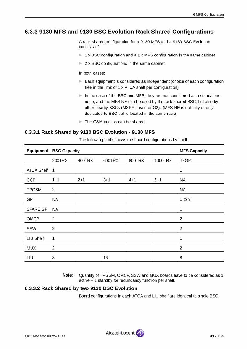
6 MFS Configuration
6.3.3 9130 MFS and 9130 BSC Evolution Rack Shared Configurations
A rack shared configuration for a 9130 MFS and a 9130 BSC Evolutionconsists of:
1 x BSC configuration and a 1 x MFS configuration in the same cabinet
2 x BSC configurations in the same cabinet.
In both cases:
Each equipment is considered as independent (choice of each configuration
free in the limit of 1 x ATCA shelf per configuration)
In the case of the BSC and MFS, they are not considered as a standalonenode, and the MFS NE can be used by the rack shared BSC, but also by
other nearby BSCs (MXPF based or G2). (MFS NE is not fully or onlydedicated to BSC traffic located in the same rack)
The O&M access can be shared.
6.3.3.1 Rack Shared by 9130 BSC Evolution - 9130 MFSThe following table shows the board configurations by shelf.
Equipment BSC Capacity MFS Capacity
200TRX 400TRX 600TRX 800TRX 1000TRX "9 GP"
ATCA Shelf 1 1
CCP 1+1 2+1 3+1 4+1 5+1 NA
TPGSM 2 NA
GP NA 1 to 9
SPARE GP NA 1
OMCP 2 2
SSW 2 2
LIU Shelf 1 1
MUX 2 2
LIU 8 16 8
Note: Quantity of TPGSM, OMCP, SSW and MUX boards have to be considered as 1active + 1 standby for redundancy function per shelf.
6.3.3.2 Rack Shared by two 9130 BSC EvolutionBoard configurations in each ATCA and LIU shelf are identical to single BSC.
3BK 17430 5000 PGZZA Ed.14 93 / 154

6 MFS Configuration
6.3.4 MFS Clock Synchronization
There are two modes:
The autonomous mode, whereby each GPU receives the clock signal on
dedicated E1s (at least two links for redundancy)
The centralized mode, whereby two dedicated GP receive the clock signal
on dedicated E1s and transmit it to the other GPs.The 9130 MFS Evolution allows 12 E1 per GP with centralized clock.
In order to support the 12E1/GP in centralised mode, the MFS should be athardware level according to HTS 1.4.3.
The selection of the set of two E1 is done:
Based on the configured links
With the following priorities: TC then 9130 BSC, then SGSN.
During the MFS installation with a centralized clock, the operator must firstconfigure the E1 that is physically connected first.
94 / 154 3BK 17430 5000 PGZZA Ed.14
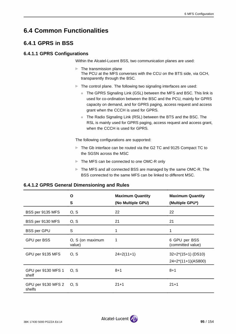
6 MFS Configuration
6.4 Common Functionalities
6.4.1 GPRS in BSS
6.4.1.1 GPRS ConfigurationsWithin the Alcatel-Lucent BSS, two communication planes are used:
The transmission planeThe PCU at the MFS converses with the CCU on the BTS side, via GCH,transparently through the BSC.
The control plane. The following two signaling interfaces are used:
The GPRS Signaling Link (GSL) between the MFS and BSC. This link is
used for co-ordination between the BSC and the PCU, mainly for GPRScapacity on demand, and for GPRS paging, access request and access
grant when the CCCH is used for GPRS.
The Radio Signaling Link (RSL) between the BTS and the BSC. TheRSL is mainly used for GPRS paging, access request and access grant,
when the CCCH is used for GPRS.
The following configurations are supported:
The Gb interface can be routed via the G2 TC and 9125 Compact TC to
the SGSN across the MSC
The MFS can be connected to one OMC-R only
The MFS and all connected BSS are managed by the same OMC-R. The
BSS connected to the same MFS can be linked to different MSC.
6.4.1.2 GPRS General Dimensioning and Rules
O
S
Maximum Quantity
(No Multiple GPU)
Maximum Quantity
(Multiple GPU*)
BSS per 9135 MFS O, S 22 22
BSS per 9130 MFS O, S 21 21
BSS per GPU S 1 1
GPU per BSS O, S (on maximumvalue)
1 6 GPU per BSS(committed value)
GPU per 9135 MFS O, S 24=2(11+1) 32=2*(15+1) (DS10)
24=2*(11+1)(AS800)
GPU per 9130 MFS 1shelf
O, S 8+1 8+1
GPU per 9130 MFS 2shelfs
O, S 21+1 21+1
3BK 17430 5000 PGZZA Ed.14 95 / 154

6 MFS Configuration
O
S
Maximum Quantity
(No Multiple GPU)
Maximum Quantity
(Multiple GPU*)
Number of GCHsimultaneouslyallocated per GPU
S 240 240
Number of GCHsimultaneouslyallocated per GP
S 1560 1560
Number of PDCHreached on GP
S 960 PDCH CS-2
912 PDCH MCS-1
784 PDCH CS-4/MCS-5
520 PDCH MCS-6
390 PDCH MCS-7
312 PDCH MCS-9
960 PDCH CS-2
912 PDCH MCS-1
784 PDCH CS-4/MCS-5
520 PDCH MCS-6
390 PDCH MCS-7
312 PDCH MCS-9
Atermux 9120BSS-9135MFS
O 8 17 (minimum (aterMux-1, nb.GPU*8))
Atermux 9120BSS-9130MFS
O 6 17 (minimum (aterMux-1, nb.GPU*6))
Atermux 9130BSS-MFS
O 16 48 (or 46 in case ofHSL)
Cells / GPU AB S 264 264
Cells / GPU AC S 264 264
Cells / GP S 500 500
Cells / 9135 MFS S 2000 2000
Cells / 9130 MFS S 4000 4000
Frame Relay BC / GPU O, S 120 120
BVC per GPU AB S 266 266
BVC per GPU AC S 266 266
BVC per GP S 500 500
TRX with PDCH perCell
O,S 16 16
Allocated PDCH perTRX
S 8 8
NSE per 9135 MFS O, S 30=2*(15)(DS10)
22=2*(11)(AS800)
30=2*(15)(DS10)
22=2*(11)(AS800)
96 / 154 3BK 17430 5000 PGZZA Ed.14

6 MFS Configuration
O
S
Maximum Quantity
(No Multiple GPU)
Maximum Quantity
(Multiple GPU*)
NSE per 9130MFS O, S 21 21
Allocated GICs perBSC
480=4*120 2000
BVC-PTP 240 240
NS-VC per NSE O, S 120 120
Bearer Channel perMFS
O, S 300 300
Bearer Channel PerPCM
O, S 31 31
PVC per BC S 1 1
SGSN_IP_Endpointper GPU
O, S 1 1
O : Operator Choice
S : System Check
* : GPU concerns the logical unit, and GP is expressed for 9130 MFS.
Table 21: GPRS General Dimensioning
The following rules and recommendations apply:
CS traffic going through the MFS is transparently connected. The
cross-connection capacity in the MFS is at the 64k TS level.
Gb traffic going to the TC is routed transparently at the TC site
There is no GPRS traffic directly on the BSC-TC Atermux
Maximum 1 GSL per Atermux. The GSL is located on TS28 of the 2nd
tributary
When frame relay (Gb) is supported on a PCM, bearer channels on thisPCM are organized in a bundle of N*64Kbit/s TS. These TS are consecutive.
N=1..31.
Atermux TS routed transparently at TC site are supported by a single
tributary at A interface
The AS800/DS10 MFS supports 8 BSC/MFS links (and 32 gicGroupinstances per GPU). The 9130 MFS supports up to 16 BSC/9130 MFS links
(and up to 52 gicGroup instances per GP).
3BK 17430 5000 PGZZA Ed.14 97 / 154

6 MFS Configuration
6.4.2 LCS in BSS
6.4.2.1 IntroductionLocation Services (LCS) are new end-user services which provide thegeographical location of a mobile station (i.e. longitude, latitude and optionallyaltitude).
LCS are applicable to any target mobile station, whether or not the mobilestation supports LCS, but with restrictions concerning the choice of positioningmethod when LCS or individual positioning methods are not supported bythe mobile station.
The LCS functions resides in an entity (including the mobile station) within thePLMN, or in an entity external to the PLMN.
LCS provides the position of the target mobile station. Depending on thepositioning techniques.
6.4.2.2 Logical ArchitectureLCS support requires new functions in the network sub-system, and optionally,on the radio side, depending on the positioning technique and on the networksynchronization.
These new functions are respectively:
The Gateway Mobile Location Center (GMLC)
The Serving Mobile Location Center (SMLC).
The following figure shows the LCS logical architecture.
BTS
BTSBSC
SMLC
MFS
Router
SAGI
LSN1 LSN2
SGSN
MSC
GMLC
HLR
Lg
Lg
Lh
GsInterface
LbInterface
Gb Interface
A Interface
MS
A−GPSServer
Figure 13: Generic LCS Logical Architecture
98 / 154 3BK 17430 5000 PGZZA Ed.14

6 MFS Configuration
As shown:
The GMLC is the first NE serving external Location Application (LA) access
in a GSM PLMN. The GMLC requests routing information from the HomeLocation Register (HLR) via the Lh interface. After performing registration
authorization, it sends positioning requests to the MSC and receives final
location estimates from the MSC or the SGSN via the Lg interface.
The SMLC is the NE which serves the client. The SMLC manages the
overall coordination and scheduling of the resources required to performingmobile station positioning. The SMLC calculates the final location estimate
and accuracy to obtain the radio interface measurements required to locate
the mobile station in the area it serves. The SMLC is connected to theBSS (via the Lb interface).
6.4.2.3 BSS and Cell ConfigurationLCS is an optional feature in the Alcatel-Lucent BSS. This feature can beblocked by the manufacturer. When provided to the customer, LCS can beenabled or disabled by the operator at cell level.
To have LCS support for a cell, the operator must:
Attach the BSC to an MFS in order to declare the BSC in the MFS. Thisleads to the download of the BSS configuration (GPRS and LCS-related
attributes of the BSS, even if GPRS or LCS is not supported) in the MFS
Provide the geographical coordinates of the cell
Activate GPRS for the cell (i.e. set the MAX_PDCH to > 0, so that the cell islocked for GPRS if the operator does not want to have GPRS running on
this cell)
Configure all the required transmission resources (Ater and Gb resources)
on the GPU(s) connected to the BSC
Activate LCS (by setting the EN_LCS flag, the common BSC/MFSparameter, to true ) on the BSS handling the cell
Enable at least one of the following flags: EN_CONV_GPS,
EN_MS_ASSISTED_AGPS, EN_MS_BASED_AGPS
Enable the EN_SAGI flag, to indicate whether the SAGI interface isconfigured for the BSS (physical and transport level configuration) for
GPS LCS only.
Ater resources are required (GSL, Gb).
The OMC-R provides centralized management of the LCS.
3BK 17430 5000 PGZZA Ed.14 99 / 154

6 MFS Configuration
6.4.2.4 RulesThe following rules apply:
LCS is supported in the CS domain
A-GPS positioning methods can be used if the new SAGI interface has
been installed
An MFS with a router in front presents one IP address to the GPS server.
Reciprocally, the GPS server presents one IP address to a router in front ofthe MFS
The router is external to the MFS, which implies that it is not supervised by
the MFS. The declaration of SAGI interface is supported by a EN_SAGIflag defined on a per BSS basis.
6.4.3 HSDS in BSS
6.4.3.1 Definitions and PrerequisitesThe High Speed Data Service (HSDS) consists of:
A basic service to offer CS3 and CS4 for GPRS and MCS1 to MCS9for EGPRS (two optional features)
Additional functions such as:
Adapting radio resource allocation in order to take into account E-GPRS
mobile station
The ability to avoid Ater blocking.
EGPRS is 2.5 to 3 times more efficient than GPRS, regardless of the frequencyband, the environment and the mobile velocity.
EDGE is available in 9100 BSS with minimum impact on the network.There is no hardware impact on the MFS and the BSC, and the 9100 BTSis EDGE-ready simply by plugging in the EDGE-capable TRX where andwhen it is needed.
100 / 154 3BK 17430 5000 PGZZA Ed.14

6 MFS Configuration
GPRS Coding Schemes
Two new coding schemes exist for GPRS in release B9:
CS-3
CS-4.
The following table lists the coding schemes and the corresponding modulationtypes and maximum transmission rates.
Scheme Modulation Maximum Rate [Kbps] per Radio TS
CS-4 GMSK 20
CS-3 GMSK 14.4
CS-2 GMSK 12
CS-1 GMSK 8
Table 22: GPRS Coding Schemes
E-GPRS Modulation and Coding Schemes
E-GPRS enables the support of data transmission at a bit rate which exceedsthe capabilities of GPRS.
E-GPRS relies on new modulation and coding schemes on the air interface,allowing a data throughput which is optimized with respect to radio propagationconditions (referred to as link adaptation).
The basic principle of link adaptation is to change the Modulation and CodingSchemes (MCS) according to the radio conditions. When the radio conditionsworsen, a more protected MCS (more redundancy) is chosen for a lowerthroughput. When the radio conditions become better, a less protected MCS(less redundancy) is chosen for a higher throughput.
Nine modulation and coding schemes are proposed for enhanced packet datacommunications (E-GPRS), providing raw RLC data rates ranging from 8.8kbit/s (the minimum value under the worst radio propagation conditions perTS) up to 59.2 kbit/s (the maximum value achievable per TS under the bestradio propagation conditions). Data rates above 17.6 kbit/s require that 8-PSKmodulation is used on the air interface, instead of the regular GMSK.
The following table lists the coding schemes and the corresponding modulationtypes and maximum transmission rates.
Scheme Modulation Maximum Rate [Kbps] per Radio TS
MCS-9 8-PSK 59.2
MCS-8 8-PSK 54.4
MCS-7 8-PSK 44.8
MCS-6 8-PSK 29.6 A/27.2 A padding
MCS-5 8-PSK 22.4
3BK 17430 5000 PGZZA Ed.14 101 / 154

6 MFS Configuration
Scheme Modulation Maximum Rate [Kbps] per Radio TS
MCS-4 GMSK 17.6
MCS-3 GMSK 14.8 A/13.6 A padding
MCS-2 GMSK 11.2
MCS-1 GMSK 8.8
Table 23: EGPRS Modulation and Coding Schemes
HSDS
HSDS provides support for GPRS with CS1 to CS4, and for E-GPRS withMCS1 to MCS9.
There are 3 families of modulation and coding schemes:
Family A: MCS3, MCS6, MCS8 and MCS9
Family B: MCS2, MCS5 and MCS7
Family C: MCS1 and MCS4.
Each family has a different unit of payload:
37 bytes: family A
34 bytes: family A padding (MCS3, MCS6 and MCS8)
28 bytes: family B
22 bytes: family C.
The different code rates within a family are achieved by transmitting a differentnumber of payload units within one radio block.
When four payload units are transmitted, these are split into two separate RLCblocks (i.e. with separate sequence numbers).
When a block has been retransmitted with a given MCS, it can be retransmitted(if needed) with a more robust MCS of the same family.
102 / 154 3BK 17430 5000 PGZZA Ed.14

6 MFS Configuration
The following figure shows the choice of modulation schemes.
GMSK 8PSK
MCS1 MCS2 MCS3 MCS4 MCS5 MCS6 MCS7 MCS8 MCS9
FamilyC
FamilyB
FamilyA
padding
FamilyA
RLC Data Block Unit of Payload (in bytes)
22 22 22
28 28 28 28 28
28 28
34+3 34+3 34+3 34 34
34 34
37 37
37 37
37 37 37
The choice of modulation schemes is based on the measurement of thebit error probability (BEP).
The coding scheme and the radio modulation rates are modified to increase thedata traffic throughput of a given radio TS. This implies that the increase ofthroughput is handled on the Abis and Ater interfaces (previously, for each radioTS in use, only a 16kb/s nibble was allocated on both interfaces).
Ater interface
In order to handle a throughput higher than 16Kb/s on the Ater interface,several Ater nibbles are dynamically allocated by the MFS Telecom.
Abis Interface
On the Abis interface, to handle a throughput higher than 16Kb/s, severalAbis nibbles are also used. The configuration is dynamic for TRX insidethe same BTS.
A number of 64k EXTS (Extra TS) are defined for each BTS by O&M. Thisgroup of TS replaces the number of transmission pool types used previously.
Due to the increase in Abis resource requirements, a single Abis link may notbe enough to introduce HSDS into a large BTS configuration. In this case, asecond Abis link is required (see Two Abis Links per BTS (Section 7.9) ).
M-EGCH
This term is used to refer to a link established between the MFS and the BTS.
One M-EGCH is defined per TRX.
3BK 17430 5000 PGZZA Ed.14 103 / 154

6 MFS Configuration
Enhanced Transmission Resource Management
A dedicated manager sequences the GCH establishment, release, redistributionor pre-emption procedures.
The transmission resource manager is on the MFS/GPU level. It handles bothAbis and Ater resources (GCH level).
It is in charge of:
Creating and removing the M-EGCH links
Selecting, adding, removing, and redistributing GCHs over the M-EGCH
links
Managing transmission resource preemptions
Managing Abis and/or Ater congestion states
Optionally, monitoring M-EGCH links usage, depending on the (M)CS oftheir supported TBFs (UL and DL).
Abis Nibble Rule
To ensure that each cell of a given BTS is able to support PS traffic at all times,there must be a minimal number of Abis nibbles for every cell in the BTS.
Ater Nibble Rules
A given amount of Ater transmission resource is allocated per GPU. Afterwards,this Ater transmission resource is shared among the 4 DSPs of the GPU,via the GPU on-board Ater switch.
Only 64K Ater TS are handled at GPU level between the DSPs. Therefore,a 64K Ater TS is moved from one DSP to another if, and only if, all of itsfour 16K Ater nibbles are free. This is the unique restriction concerning Aternibble sharing at GPU level.
104 / 154 3BK 17430 5000 PGZZA Ed.14

6 MFS Configuration
6.4.3.2 Transmission PowerGMSK Output Power
GMSK is a constant amplitude modulation.
8-PSK Output Power
For one given TRE, the maximum output power is lower in 8-PSK than in GMSKbecause of the 8-PSK modulation envelope which requires a quasi-linearamplification.
The TRE transmit power in 8-PSK does not exceed the GMSK transmit powerin the sector and in the band.
8-PSK is a varied digital phase modulation.
Leveling of 8-PSK Output Transmission Power is new in release B8.
For a TRE, there is a major difference in the output transmission power betweenthe GMSK and the 8-PSK modulation. This is shown in the following table.
G4 TRE MediumPower
G4 TRE HighPower
GMSK (CS1-CS2/MCS1-MCS4) 46.5 dBm 47.8 dBm
8-PSK (MCS5-MC9) 41.8 dBm 44.0 dBm
Table 24: GMSK and 8-PSK Transmission Power Differences
The following table shows the output power values for GERAN TRA.
GERAN TRA / EDGE+ TRA
RIT name GMSK power 8-PSK power Ref Sensitivity
GSM900 GTT09 2*45 W / 46,5 dBm 2*30 W / 44,8 dBm - 116 dBm Twin TRA
GTH09 90W / 49,5 dBm 40W / 46,0 dBm - 119 dBm HP / 4 RXTRA
DCS1800 GTT18 2*35 W / 45,4 dBm 2*30 W / 44,8 dBm - 116 dBm Twin TRA
GTH18 70W / 48,5 dBm 30W / 44,8 dBm - 119 dBm HP / 4 RXTRA
GSM850 GTM08 45 W 30W
60W 40W
PCS1900 GTM19 35 W 30W
60W 30W
The E-GPRS TBF can be allocated on the BCCH TRX, and the BCCHfrequency must have a quite stable radio transmission power.
3BK 17430 5000 PGZZA Ed.14 105 / 154

6 MFS Configuration
The Modulation Delta Power is the difference between the GMSK output powerof the sector for the TRE band, and the 8-PSK output power of the TRE.According to the 8-PSK delta power value, a TRE is called "High Power" or"Medium Power". 8-PSK High Power Capability is true if Modulation DeltaPower is less than 3 dB.
6.4.3.3 RulesThe following rules apply:
TCU Allocation:
Extra Abis TS are allocated only on the FR TCU
RSL, OML and TCH are mapped on a TCU, regardless of extra Abis TS
Extra Abis TS are moved automatically from one TCU to another.
Allocation priorities (from highest to lowest)
PS TRX/TRE are ordered according to the following rules:
PS allocation is preferred on the BCCH TRX. PS_PREF_BCCH_TRX
indicates whether or not the PS requests will be preferentially servedwith PDCH(s) of the BCCH TRX
0: No preference. The TRX ranking algorithm handles the BCCH
TRX as a non-BCCH TRX
1: PS requests preferentially served on BCCH TRX. The TRX ranking
algorithm ensures that the BCCH TRX has the highest preference to
carry PS traffic (provided that the BCCH TRX can carry PS traffic,i.e. TRX_PREF_MARK = 0 on that TRX)
2: PS requests served on BCCH TRX with lowest priority. TheTRX ranking algorithm ensures that the BCCH TRX has the lowest
preference to carry PS traffic (provided that the BCCH TRX can carry
PS traffic, i.e. TRX_PREF_MARK = 0 on that TRX).
The TRE hardware capability
G4 TRE or 9110-E Micro BTS is preferentially used for PS allocation
TRE with 8-PSK HP capability is preferentially used for PS allocation
The DR TRE configuration is preferentially used for CS allocations
The maximum PDCH group criterion
The TRX Identifier.
BTS configuration
Only 9100 BTS (including 9100 Micro-BTS) support the HSDS
A mix of the G4 TRE medium power and G4 TRE high power (that
offers a higher output power useful for 8-PSK modulation) in the same9100 BTS is allowed
To support MCS1 to MCS9, an 9100 BTS must be upgraded with some
G4 TREs
TWIN TRA is supported only with SUMA, not with SUMP.
106 / 154 3BK 17430 5000 PGZZA Ed.14

6 MFS Configuration
For BSC connectivity, two A-bis extra timeslots are equivalent to one FullRate TRX
The maximum number of Extra Timeslots in the BSC is 717
MFS capacity:
The MFS capacity is defined by the maximum throughput of the GPU
The maximum throughput of the GPU is the minimum of:
PPC maximum throughput
4 x DSP maximum throughput.
For example, for a 9135 MFS, the maximum throughput for a DSP, in one
direction, is about 800 kbit/s for pure GPRS and 1 Mbit/s with E-GPRS(with some assumptions regarding MCS and CS distribution)
The support of 8PSK in UL is optional for the mobile station
MAX_EGPRS_MCS = MCS-2 must be avoided.
3BK 17430 5000 PGZZA Ed.14 107 / 154

6 MFS Configuration
6.4.4 Gb over IP
With the introduction of GBoIP, telecom traffic towards/from the SGSN goesthrough the router from/in the MFS.
The following table lists the Gb over IP connectivity mains output.
9130 EvolutionMFS
O&M One LAN
(No RIP)
O&M Two LAN
(RIP)
Telecom OneLAN
B9 Supported Supported -
B10 Supported Supported -
B10 with GboIP Supported Not supported Supported
9135 MFS O&M One LAN
(No RIP)
O&M Two LAN
(RIP)
Telecom OneLAN
B9 Supported Not supported -
B10 Supported Not supported -
B10 with GboIP Supported Not supported Supported
Where:
For a 9130 Evolution MFS
O&M one LAN means:If O&M/Telecom flows use the same IP interface, internally the MFS usesa VLAN tag for the MFS external flows. The same VLAN tag is usedfor both O&M and telecom flows. There is one Vlan id per switch. Thisis the default topology.If O&M/Telecom flows use a different IP interface, there are differentrouters or different switching functions of the same router.In the case of router redundancy, a VRRP or VRRP-like protocol mustbe supported.
O&M two LAN means:The case of same IP interface used for O&M/Telecom flows is notsupported.The case of a different IP interface used for O&M/Telecom flows isnot recommended.
108 / 154 3BK 17430 5000 PGZZA Ed.14

6 MFS Configuration
For 9135 MFS
O&M one LAN means:If O&M/Telecom flows use the same IP interface, there are differentsubnets. This is the nominal case.If O&M/Telecom flows use a different IP interface, there is an extraIP interface on the router side.In the case of router redundancy, a VRRP or VRRP-like protocol mustbe supported.The MFS hubs must be replaced accordingly.
O&M two LAN means:This case is not applicable.
And:
Static routing solution with no RIP means:Both control station are on the same physical LAN. The two wires connectedto the router are connected to the same switching function of the router.
Dynamic routing with RIP means:The control stations are connected to two distinct LANs, one per MFSswitch. A dedicated subnet is associated with each LAN.
IP endpoints configuration can be:
StaticNS-VCs and NS-VLs can be established by administrative means.There are up to 16 SGSN IP endpoints per NSE.
DynamicNS-VCs and NS-VLs can be established by auto-configuration procedures.The client/server principle applies: the SGSN is the server, while the BSS isa client.There are up to 16 pre-configured IP endpoints per NSE.In dynamic mode, the OMC forbids the creation of a second pre-configuredendpoint.
Assumptions:
When GboIP is activated, there must be one IP address per active GPU
Gb over IP is supported on:
The 9130 Evolution MFS
The 9135 MFS with DS10 control station equipped with Alcatel-Lucent
OmniStack LS 6224 switches
The support of GBoIP needs a B10 MFS but also a B10 version of the BSSassociated with the concerned GPU.
6.4.5 Other Common Functionalities
The following elements do not change:
There is no change in the radio configuration mechanisms, and sameparameters are used
There is no change in the Ater/Gb transmission configuration and display
3BK 17430 5000 PGZZA Ed.14 109 / 154

6 MFS Configuration
The hardware supervision is still handled through the IMT
There is no change in the OMC/MFS communication.
Some boards of 9130 MFS are common with 9130 BSC: OMCP, switch, LIU,MUX, shelf manager.
In case the MFS “single secured Gb” feature is used, the GPU synchronisationin autonomous mode can be used through the BSC links or through the TC linksif the Gb and the synchronisation from the TC do not share the same Atermux.
110 / 154 3BK 17430 5000 PGZZA Ed.14

6 MFS Configuration
6.5 Delta 9130 MFS versus 9135 MFSThis section describes the main differences between the 9130 MFS andthe 9135 MFS.
The following figure shows Ater Allocation on LIU boards for a standalone MFS.
LIU 1 LIU 2 LIU 3 LIU 4 LIU 5 LIU 6 LIU 7 LIU 8 LIU 9 LIU 10 LIU 11 LIU 12 LIU 13 LIU 14 LIU 15 LIU 16
1 1 17 33 49 65 81 97 113 129 145 161 177 193 209 225 2412 2 18 34 50 66 82 98 114 130 145 162 178 194 210 226 2423 3 19 35 51 67 83 99 115 131 147 163 179 195 211 227 2434 4 20 36 52 68 84 100 116 132 148 164 180 196 212 228 2445 5 21 37 53 69 85 101 117 133 149 165 181 197 213 229 2456 6 22 38 54 70 86 102 118 134 150 166 182 198 214 230 2467 7 23 39 55 71 87 103 119 135 151 167 183 199 215 231 2478 8 24 40 56 72 88 104 120 136 152 168 184 200 216 232 2489 9 25 41 57 73 89 105 121 137 153 169 185 201 217 233 249
10 10 26 42 58 74 90 106 122 138 154 170 186 202 218 234 25011 11 27 43 59 75 91 107 123 139 155 171 187 203 219 235 25112 12 28 44 60 76 92 108 124 140 156 172 188 204 220 236 25213 13 29 45 61 77 93 109 125 141 157 173 189 205 221 237 25314 14 30 46 62 78 94 110 126 142 158 174 190 206 222 238 25415 15 31 47 63 79 95 111 127 143 159 175 191 207 223 239 25516 16 32 48 64 80 96 112 128 144 160 176 192 208 224 240 256
Configurations for 4, 9, and 21 GPUs Colors shown affectation of LIU per GPU
GPU 1, 5, 9, 13, 17, 21
GPU 2, 6, 10, 14, 18
GPU 3, 7, 11, 15, 19
GPU 4, 8, 12, 16, 20
21 x GPU
4 x GPU9 x GPU
3BK 17430 5000 PGZZA Ed.14 111 / 154

6 MFS Configuration
The following figure shows Ater Allocation on LIU boards for MFS with onlyone subrack.
LIU 1 LIU 2 LIU 3 LIU 4 LIU 5 LIU 6 LIU 7 LIU 8 LIU 9 LIU 10 LIU 11 LIU 12 LIU 13 LIU 14 LIU 15 LIU 161 1 17 33 49 65 81 97 113 129 145 161 177 193 209 225 2412 2 18 34 50 66 82 98 114 130 145 162 178 194 210 226 2423 3 19 35 51 67 83 99 115 131 147 163 179 195 211 227 2434 4 20 36 52 68 84 100 116 132 148 164 180 196 212 228 2445 5 21 37 53 69 85 101 117 133 149 165 181 197 213 229 2456 6 22 38 54 70 86 102 118 134 150 166 182 198 214 230 2467 7 23 39 55 71 87 103 119 135 151 167 183 199 215 231 2478 8 24 40 56 72 88 104 120 136 152 168 184 200 216 232 2489 9 25 41 57 73 89 105 121 137 153 169 185 201 217 233 249
10 10 26 42 58 74 90 106 122 138 154 170 186 202 218 234 25011 11 27 43 59 75 91 107 123 139 155 171 187 203 219 235 25112 12 28 44 60 76 92 108 124 140 156 172 188 204 220 236 25213 13 29 45 61 77 93 109 125 141 157 173 189 205 221 237 25314 14 30 46 62 78 94 110 126 142 158 174 190 206 222 238 25415 15 31 47 63 79 95 111 127 143 159 175 191 207 223 239 25516 16 32 48 64 80 96 112 128 144 160 176 192 208 224 240 256
Configurations for 4, 9 GPUs Colors shown affectation of LIU per GPUGPU 1, 5
GPU 2, 6
GPU 3, 7
GPU 4, 8
4 x GPU8 x GPU
The following figure shows Ater Allocation on LIU boards for MFS which arerack shared with the BSC.
LIU 1 LIU 2 LIU 3 LIU 4 LIU 5 LIU 6 LIU 7 LIU 8 LIU 9 LIU 10 LIU 11 LIU 12 LIU 13 LIU 14 LIU 15 LIU 16
1 1 17 33 49 65 81 97 113 129 145 161 177 193 209 225 241
2 2 18 34 50 66 82 98 114 130 145 162 178 194 210 226 242
3 3 19 35 51 67 83 99 115 131 147 163 179 195 211 227 243
4 4 20 36 52 68 84 100 116 132 148 164 180 196 212 228 244
5 5 21 37 53 69 85 101 117 133 149 165 181 197 213 229 245
6 6 22 38 54 70 86 102 118 134 150 166 182 198 214 230 246
7 7 23 39 55 71 87 103 119 135 151 167 183 199 215 231 247
8 8 24 40 56 72 88 104 120 136 152 168 184 200 216 232 248
9 9 25 41 57 73 89 105 121 137 153 169 185 201 217 233 249
10 10 26 42 58 74 90 106 122 138 154 170 186 202 218 234 250
11 11 27 43 59 75 91 107 123 139 155 171 187 203 219 235 251
12 12 28 44 60 76 92 108 124 140 156 172 188 204 220 236 252
13 13 29 45 61 77 93 109 125 141 157 173 189 205 221 237 253
14 14 30 46 62 78 94 110 126 142 158 174 190 206 222 238 254
15 15 31 47 63 79 95 111 127 143 159 175 191 207 223 239 255
16 16 32 48 64 80 96 112 128 144 160 176 192 208 224 240 256
Configurations with 4 and 8 GPUs in rack shared with option 16 E1 /GP Colors shown affectation of LIU per GPUGPU 1, 5
GPU 2, 6
GPU 3, 7
GPU 4, 8
4 x GPU8 x GPU
Because the spare GP is not fixed, the mapping changes after switchover.
112 / 154 3BK 17430 5000 PGZZA Ed.14

6 MFS Configuration
The 9130 MFS differs from the standard MFS as follows:
The GP replaces the current GPU
The E1 termination shelf replaces the E1 appliques, with the advantage of
separating processing from transmission
No spare physical GP (still N+1 protection scheme)
In the 9130 MFS, there are only 12/14/16 ports per GP
The fixed synchronization mode does not exist. The clock synchronization is
transmitted over Ethernet (nE1oE) from the E1 board. It is received on thespecific virtual E1 links of the GP and can be configured, as is the case
in the autonomous mode or centralized mode.
Control stations are replaced by the OMCP board
There is a new operating system (OS), and a new Tomas
Installation is via .xml scripts
The 9130 BSC can be used as clock synchronization
For more information about configurations with O&M connection via the 9130BSC, refer to BSS Routing Configurations document.
3BK 17430 5000 PGZZA Ed.14 113 / 154

6 MFS Configuration
114 / 154 3BK 17430 5000 PGZZA Ed.14

7 Abis Interface
7 Abis Interface
This section describes the Abis interface, and corresponding features andfunctions.
The Abis interface is standard ITU-T G.703 / G.704 interface. It is based on aframe structure. The frame length is 256 bits grouped in 32 TS, numbered from0 to 31. The rate of each TS is 64 Kbit/s.
3BK 17430 5000 PGZZA Ed.14 115 / 154

7 Abis Interface
7.1 Abis Network Topology and TransportFrom a functional point of view, two topologies exist to physically connectthe BTS to the BSC:
Open multi-drop topology "CHAIN"One PCM link connects up to 15 BTS in serial order and the PCM is notlooped back to BSC by the last BTS.In a chain topology, the BSC is connected by the Abis link to a BTS. TheBTS is connected to a second BTS with a second Abis link, and the secondBTS is in turn connected to a third BTS, and so on.
Note: A star topology is a particular case of a chain with one BTS.The following figure shows a chain topology.
Abis link
BSCBTS BTSBTS
Chain Topology
Figure 14: Chain Topology
Closed multi-drop topology "RING"One PCM link connects up to seven BTS in serial order and the PCM islooped back to BSC by the last BTS.In a ring or loop topology, the last BTS of a chain is connected backto the BSC. This topology provides security as traffic between any BTSand BSC is broadcast on the two paths, and the selection is based ondedicated service bits and bytes.The following figure shows a ring or loop topology.
BTSBTS
Chain Topology Abis link
BSC
BTS
Figure 15: Ring or Loop Topology
116 / 154 3BK 17430 5000 PGZZA Ed.14

7 Abis Interface
There are several ways of transporting Abis over networks (the following listis not exhaustive):
A terrestrial link referred to as the PCM 2Mbit/s link (64 Kbit/s * 32 Timeslots
= 2048 Kbit/s)
A microwave link (same capacity or higher)
Digital cross-connect network equipment, which concentrates 4, 16 or 64
PCM 2Mbit/s link
A microwave hub equivalent to DCN
A satellite link.
7.2 ImpedanceThere are two types of impedance which define the access to the transmissionnetwork:
120 Ohm balanced two twisted pairs
75 Ohm unbalanced two coaxial cables.
Note: It is forbidden to mix impedance in the same BSS.
3BK 17430 5000 PGZZA Ed.14 117 / 154

7 Abis Interface
7.3 Abis Channel Types
7.3.1 Overview
Three types of channels are mapped in Abis trunks:
The Qmux channel is used by TSC O&M transmission supervision and for
the configuration of non 9100 BTS (G1 and G2 BTS)
The ring control channel RS bits used in rings
Three types of BTS channel:
TCH channels: eight per TRX
HDLC channels which can carry one or more LAPDs
Extra Abis TS.
Mapping on BTS channels on E1 is defined by:
The TS bearing the Qmux
The presence (or not) of the ring control channel
Allocation rules managing the PCM TS to the BTS via MultiplexedChannel Blocks.
7.3.2 TS0 Use
There are two TS0 modes:
TS0 UsageTS0 usage means that the TS0 carries Qmux.TS0 usage is not supported by the 9130 BSC.
TS0 TransparencyThe Qmux is carried by any other TS from TS1 to TS31 (TS0 does notcarry Qmux).TS0 transparency is strongly recommended.
118 / 154 3BK 17430 5000 PGZZA Ed.14

7 Abis Interface
7.4 Signaling Link on Abis Interface
7.4.1 RSL and OML
The GSM Recommendation 08.52 defines two logical links between the BTSand the BSC:
The Radio Signaling Link (RSL) is used for supporting traffic managementprocedures (mobile station to network communication)
The Operation and Maintenance Link (OML) is used for supporting network
management procedures.
Signaling for GPRS traffic is carried over the RSL and/or GCH.
7.4.2 Qmux Bus
A link-denoted Qmux manages and supervises the transmission function of theBSS equipment. This is based on a service Qmux master/slave bus principle.
The Qmux only is necessary for G1 and G2 BTS.
For transmission function management, the NEs are connected to this Qmuxbus and are in slave mode. An O&M entity referred to as the TranscoderSub-multiplexer Controller (TSC) is the master for the 9120 BSC and the TP forthe 9130 BSC Evolution.
Note: The Qmux bus are replaced by Abis links for 9100 BTS, via the TransmissionManagement by the OMU feature. Supervision is then managed throughthe OML.
7.4.3 OML Autodetection
An onsite visit is necessary to update the OML location. The BTS cannotautonomously take into consideration any change of OML address during aMove BTS, hence the development of OML autodetection.
The BTS scans 31 TS on the Abis link to detect where its own OML linkis located. In the case of detection of an available OML, the BTS sends itsidentity (Qmux-id) to the BSC via this available OML. The BSC then reportswhether the BTS is listening to the right OML, or on which TS the BTS can findits dedicated OML.
After a reasonable delay, and without any onsite visit by a technician, the BTSautomatically reestablishes a link to the BSC.
This behavior is available only for 9100 BTS.
3BK 17430 5000 PGZZA Ed.14 119 / 154
7 Abis Interface
7.5 Signaling Link Multiplexing
7.5.1 Signaling Link Multiplexing Options
The following Signaling Link Multiplexing options apply:
No multiplexing
Static multiplexing of RSL 4*16Kbit/s in one TS. The OML is in anotherTS. Static submultiplexing is not compatible with half rate configurations
(RSL capacity).
64K statistic multiplexing with HR flexibility
A new signaling load parameter (low/high) entered by the operator allowsthe BSC to determine the multiplexing scheme according to:
Normal: 4:1 (resp. 2:1) maximum multiplexing scheme for FR TRX
(resp. for DR TRX)
High 2:1 (resp. for 1:1) maximum multiplexing scheme for FR TRX
(resp. for DR TRX).
The operator gives the number of TRE per sector from the list of TREdeclared during BTS creation. This number must be taken as the DR TRE ineach sector and, in the case of a multiband sector, in each band.
Statistical submultiplexing one RSL and (possibly) one OML, both at 16Kbit/s in the TCH corresponding to the first TS of each TRE.
Note: Three RSLs cannot be multiplexed on one Abis timeslot.
Multiplexing can be done per BTS or per sector.
For example, a BTS with two sectors with two TREs (Full Rate) and one sectorwith four TREs (Full Rate), note for RSL x/y, x=Sector number, y= RSL number:
If multiplexing mode = "BTS" and signalling load = "normal":
First TS = OML + RSL1/1 + RSL1/2 + RSL2/1 + RSL 2/2
Second TS = RSL3/1 + RSL 3/2 + RSL 3/3 + RSL 3/4
If the multiplexing mode is "Per sector" and the signalling load is "normal"for the first sector, "normal" for the second sector and "high" for the third
sector, then the following distribution of the OML and the RSLs over the Abistimeslots applies:
First TS = OML + RSL1/1 + RSL1/2
Second TS = RSL 2/1 + RSL2/2
Third TS = RSL 3/1 + RSL 3/2
Fourth TS = RSL 3/3 + RSL 3/4
120 / 154 3BK 17430 5000 PGZZA Ed.14
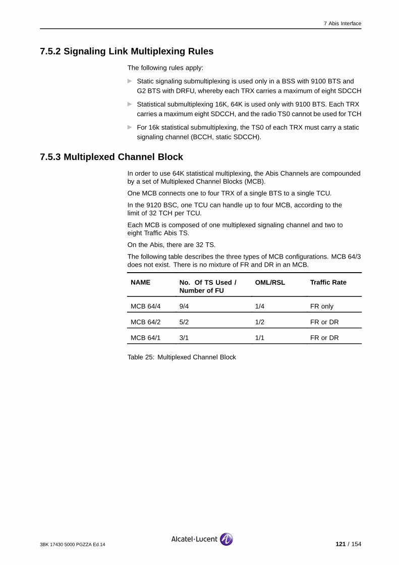
7 Abis Interface
7.5.2 Signaling Link Multiplexing Rules
The following rules apply:
Static signaling submultiplexing is used only in a BSS with 9100 BTS and
G2 BTS with DRFU, whereby each TRX carries a maximum of eight SDCCH
Statistical submultiplexing 16K, 64K is used only with 9100 BTS. Each TRX
carries a maximum eight SDCCH, and the radio TS0 cannot be used for TCH
For 16k statistical submultiplexing, the TS0 of each TRX must carry a staticsignaling channel (BCCH, static SDCCH).
7.5.3 Multiplexed Channel Block
In order to use 64K statistical multiplexing, the Abis Channels are compoundedby a set of Multiplexed Channel Blocks (MCB).
One MCB connects one to four TRX of a single BTS to a single TCU.
In the 9120 BSC, one TCU can handle up to four MCB, according to thelimit of 32 TCH per TCU.
Each MCB is composed of one multiplexed signaling channel and two toeight Traffic Abis TS.
On the Abis, there are 32 TS.
The following table describes the three types of MCB configurations. MCB 64/3does not exist. There is no mixture of FR and DR in an MCB.
NAME No. Of TS Used /Number of FU
OML/RSL Traffic Rate
MCB 64/4 9/4 1/4 FR only
MCB 64/2 5/2 1/2 FR or DR
MCB 64/1 3/1 1/1 FR or DR
Table 25: Multiplexed Channel Block
3BK 17430 5000 PGZZA Ed.14 121 / 154

7 Abis Interface
7.6 Mapping Techniques
7.6.1 Mapping Rules
The following rules apply:
The mapping algorithm begins allocating from the highest usable TSnumber downwards, up to the lowest usable TS number, and so on. It
is entirely controlled by the BSC.
The operator can reserve Abis TS per Abis (range of TS from Tsi to TSj)(i and j from 0 to 31 and j>i). The operator can define (per BTS) the
usable TS inside the range defined on the Abis. The operator defines, TSper TS, which one correspond to which BTS. This is necessary in the
case of cross connects.
For BTS G1/G2, the two TS needed to carry the traffic channels overAbis must be contiguous
For 9100 BTS, the two TS required to carry the traffic channels over Abis donot need to be contiguous, but the first set of four traffic channels (TRX-TS
0..3) must always be on a lower Abis-TS than the second set (TRX-TS 4..7)
The Qmux, Rbits and Sbits can be mapped onto any usable TS fromTS0 to TS31
Note: For the 9130 BSC Evolution Qmux, Rbits and Sbits must not be mapped onTS0.
The OML channels can be slotted anywhere by the operator
The RSL and TCH channels are slotted in any available TS by the BSC
The RSL can exist on the second Abis
RSL and traffic channels of one MCB must be on the same PCM link
The parameters which allow to control the Abis allocation are:
Max_PS_TS primary
Max_FR_TRE_primary
Max_DR_TRE_primary.
Note: For an HSDS-configured BTS, refer to the mapping rules (extra Abis nibbles;OML mandatory on first Abis) described in HSDS in BSS (Section 6.4.3).
122 / 154 3BK 17430 5000 PGZZA Ed.14

7 Abis Interface
7.6.2 Abis-TS Defragmentation Algorithm
Certain types of BTS require that the TCH of a TRE are mapped on twoconsecutive 64Kbit/s PCM TS. There are no rules for the signaling links.
Therefore, for BTS or TRE hardware extensions, two contiguous 64 Kbit/s PCMTS may be required, while only two (or more) isolated PCM TS are free. Analgorithm must be run that creates two consecutive free TS, with minimumtraffic disturbance. This is referred to as defragmentation.
The operator can only add one TRE at a time. This operation is extremelyrare (there is no reason to have holes of one TS on Abis, and there is noextension of G1/G2 BTS).
There is never any need to create in advance more couples of free PCM TSthan are required, as this would just lead to unnecessary traffic interruptions. Itis available only for G1 and G2 BTS.
7.6.3 RSL Reshuffling Algorithm
Note: This section refers only to 9120 BSC.
The RSL_Reshuffle is triggered by an explicit operator command (OMC-R) inthe case of an Add BTS operation.
The RSLs inside one TCU must be moved to make room for new BTSextensions within this TSU.
The RSL_Reshufle is also used to spread the MCB in order to spread SDCCH.
The following algorithms must ensure that FR and DR TCU are not mixed:
An MCB is either FR or DR and can only be mapped onto a TCU of thesame type
Extra Abis TS can only be mapped onto FR TCU
An empty TCU (without any MCB and extra Abis TS) can be set to FR or DR.
The sequence for remapping RSL/TRX and for programming the BIUA will bereversed to reduce telecom outage. The scenario is as follows:
1. Construct a new RSL/TRX mapping and save this mapping in the DLS.
2. Reprogram the BIUA based on this new mapping.
3. Activate the new RSL/TRX mapping in the BSC.
Each of these blocks are secured against take over, etc... Point (1) and (3) areprotected with a rollback mechanism.
With HR flexibility, the reshuffling algorithm is kept but the reshuffling process isto be conducted independently for each TCU type.
3BK 17430 5000 PGZZA Ed.14 123 / 154

7 Abis Interface
7.6.4 Cross-Connect Use on Abis
When cross-connects are used on the Abis, different numbers may be requiredfor the Abis TS used by the BTS (Qmux bus, OML, RSL and TCHs) on theBTS connector and on the BSC connector. This flexibility is supported bythe introduction of a TS mapping table between the BTS connectors andthe BSC connectors.
The TS mapping table is introduced by the operator via the OMC-R andapplied by the BSC when a new BTS-BIE configuration is required, due toa modification of the Abis TSs allocation. In order to keep the release B6principle of auto-allocation of TREs, this TS mapping table is introduced duringthe "Create an Abis chain/ring" operation. Also, in order to maintain a relativeflexibility on the TS allocation within the TS reserved for each branch connectedto the cross-connect, the operator must also be able to select the TS which canbe used by each BTS during the "Create BTS" operation.
At the OMC-R, the operator can change usable Abis TS, usable BTS TSand cross-connect tables.
The following figure provides an example of cross-connect use on the Abis.
BSC
BTS2
BTS3
BTS1
BTS 1 TS 2 to 4BTS 2 TS 11 to 15BTS 3 TS 21 to 24
BTS 3 TS 2 to 5
BTS 2 TS 2 to 6
Branch 1
Branch 3
Branch 2
Figure 16: Example of Cross-Connect Use on Abis
The following table lists the possible TS mapping tables for the correspondingAbis chain or ring in the BSC.
TS Number for BSC side TS Number for BTS side
2 to 10 2 to 10
11 to 20 2 to 11
21 to 31 2 to 12
Table 26: TS Mapping Table for Corresponding Abis Chain or RingConfigurations
124 / 154 3BK 17430 5000 PGZZA Ed.14

7 Abis Interface
7.6.4.1 TS Use RulesThe following rules apply for TS use:
The TS which can be used for BTS 1 are 2 to 10
The TS which can be used for BTS 2 are 11 to 20
The TS which can be used for BTS 3 are 21 to 31.
When BTS 1 is created, according to the usable TS, the TS allocated for theBSC connector are 10-9-8, and according to the TS mapping table, the TSallocated for the BTS-BIE are 10-9-8.
When BTS 2 is created, according to the usable TS, the TS allocated for theBSC connector are 15-14-13-12-1, and according to the TS mapping table,the TS allocated for the BTS-BIE are 6-5-4-3-2.
When BTS 1 is created, according to the usable TS, the TS allocated for theBSC connector are 24-23-22-21, and according to the TS mapping table, theTS allocated for the BTS-BIE are 5-4-3-2.
When a TRE is added to BTS 3, according to the usable TS, the TS allocatedfor the BSC connector are 27-26-25, and according to the TS mapping table,the TS allocated for the BTS-BIE are 8-7-6.
7.6.4.2 Cross-Connect Use on Abis RulesCross-connect usage on Abis is supported only if the following rules are applied:
One BTS uses (for itself and for the forwarded Abis link) only PCM TS, which
come from a single BSC connector
If Qmux is used, the BTS must be connected to the Qmux TS. The other
branch must use OML if possible (9100 BTS).
7.6.5 TCU Allocation Evolution in 9130 BSC Evolution
The TCU Allocation Evolution feature enables the removal of different rules inthe 9130 BSC Evolution due to a more flexible TCU allocation approach:
It is no longer necessary to perform a Move BTS when extending the BTS
It is possible to connect the maximum number of TRE, regardless of thetopology
Extra-TS no longer occupy TCU resources.
Note that the following rules for TCU allocation still apply:
The TCU can handle maximum of four FR TREs (four RSLs) or two FR +
one DR TRE (three RSLs) or two DR TREs (two RSLs). Therefore, theTCU can handle a maximum of four Eq. FR RSLs
The TCU can handle a maximum of three OMLs.
3BK 17430 5000 PGZZA Ed.14 125 / 154

7 Abis Interface
7.7 Abis Link CapacityThe following table lists the number of TS available in one Abis link to use forTCHs and for the signaling channel.
Supervision By Qmux By OML
TS0 Transparency Usage
Open Chain MD 30 31 31
Closed Loop MD 29 30 29
Table 27: Number of TS Available in One Abis Link
The following table lists the number of required TS versus TRE number andsub-multiplexing type in one Abis Link with FR TRE. The assumption is thatthere are no extra TS for PS traffic in this example.
Signaling Multiplex
Nb of TRX No Multiplex Static Statistical 64 Statistical 16
1 4 4 3 2
2 7 6 5 4
3 10 8 8 6
4 13 10 9 8
5 16 13 12 10
6 19 15 14 12
7 22 17 17 14
8 25 19 18 16
9 28 22 20 18
10 31 24 22 20
11 Impossible 26 26 22
12 Impossible 28 27 24
13 Impossible Impossible 30 26
126 / 154 3BK 17430 5000 PGZZA Ed.14

7 Abis Interface
Signaling Multiplex
14 Impossible Impossible Impossible 28
15 Impossible Impossible Impossible 30
Table 28: Number of Required TS versus TRX Number and Sub-MultiplexingType
The following table provides example FR/DR ratios according to Abis size.
N# ofTRX
DR + FRTRX
Max %HR
N# of TCURequired (DR +FR)
N# of SIG TSs
(Statistical Mux)
(Low SIG Traffic)
1 1+0 100% [frac12] + 0 1
2 1+1 66% [frac12] + [frac14] 2
3 1+2 50% [frac12] + [frac12] 2
4 1+3 40% [frac12] + [frac34] 3*
4 2+2 66% 1 + [frac12] 2
6 2+4 50% 1 + 1 2
8 2+6 40% 1 + 1 [frac12] 3
10 4+6 40% 2 + 1 [frac12] 3
10 3+7 47% 1 [frac12] + 1[frac34]
5*
10 2+8 33% 1 + 2 3
12 4+8 50% 2 + 2 4
14 2+12 25% 1+3 4
* : These numbers result from the need to split any group of 3 TREs as 2+1 tofacilitate the mapping. Some other choices are possible, as shown by the table.
3BK 17430 5000 PGZZA Ed.14 127 / 154
7 Abis Interface
7.8 Abis Satellite LinksThe Abis interfaces are designed to use short terrestrial transmission links.
The operator can configure the way an Abis is carried:
Via terrestrial link, or
Via satellite.
When the link is via satellite, the system applies different parameters to wait foran acknowledgement, in order to repeat frames.
Satellite links cannot be used at the same time on the Abis interface and on theAter interface (see Ater Satellite Links (Section 8.7)).
This feature is only available for 9100 BTSs and later versions.
The following configuration rules apply:
On Abis, the satellite link is considered to be installed between the BSC andthe first BTS of the multidrop. If this is not the case, the drawback is that
timers applied on the first BTS will be unnecessarily lengthened and thisdoes not support high traffic with poor quality links.
Usually, only a part of the TS is routed via the satellite. The customer must
take care to route the required TS.
The type of connection is defined per Abis link.
For BTS where the satellite link is installed, the following features are notavailable:
Closed multidrop (Abis topology)
The BTS must be configured as a free run (no PCM synchronized) (OCXOsynchronization).
Support of fax and data (in CS mode, transparent and not transparent) dependson timers managed by the NSS part.
GPRS connections are supported over satellite links (Abis or Ater). If GPRS isactivated, there are a number of parameters to be modified.
For OML autodetection via satellite, a timer has been designed to be ableto manage the transmission delay. In that context, OML autodetection viasatellite is possible.
LCS is supported with Abis satellites.
128 / 154 3BK 17430 5000 PGZZA Ed.14

7 Abis Interface
7.9 Two Abis Links per BTS
7.9.1 Overview
If HSDS is to be introduced in a BTS configuration, and if there are not enoughAbis TS on one Abis link, a second Abis can be attached to the BTS. In thiscase, OML and basic TS and the extra TS for the TRX transmission pools aresplit over the two Abis links.
For a BTS with two Abis links, the operator defines a new parameter,MAX_EXTRA_TS_PRIMARY, which defines the maximum number of extra TS thesystem is allowed to allocate on the first Abis for this BTS.
To keep the maximum free TS on the secondary Abis, the allocation ofextra TS is done in priority on the first Abis until this Abis is full or untilMAX_EXTRA_TS_PRIMARY is reached.
In terms of the Abis topologies supported, the BTS can only manage twotermination points.
The second Abis is useful when there is not enough space on one completeAbis for all BTS TS. This means that the primary Abis must be fully assigned tothe BTS. Therefore, the secondary Abis cannot be attached to a BTS if theBTS is not alone on the primary Abis.
Consequently, only two added Abis topologies are supported.
This is shown in the following figure.
Primary Abis
Secondary Abis
SecondaryAbis
TP1 TP1
TP1
TP2 TP2
TP2
TP2Topology 1
Topology 2
EvoliumBTSor
G1/G2 BTS
EvoliumBTSor
G1/G2 BTS
EvoliumBTS
EvoliumBTS
BSC
Added Abis Topology
The primary Abis and the secondary Abis of a BTS can be on different TSU ofdifferent racks.
There are no restrictions concerning cross-connection on the primary Abis.
The system does not check for a cross-connect on the secondary Abis.Cross-connection is not supported on the secondary Abis.
3BK 17430 5000 PGZZA Ed.14 129 / 154

7 Abis Interface
7.9.2 Rules
The following rules apply:
The second Abis per BTS can be used for CS traffic
The second Abis per BTS is used for more than 12 TRX feature in one BTS
OML and basic TS are always mapped to the first link and the extra TS forthe TRX
Transmission pools are split over the two Abis links
Only an 9100 BTS with SUMA boards or 9110-E Micro BTS supportsthe second Abis link
An 9100 BTS with a SUMP board has to be upgraded. An 9100 BTS can
only manage two termination points.
This implies that it is not possible to:
Connect a BTS in chain after a BTS with two Abis
Change the Abis from chain to ring if there is a BTS with 2 Abis
Attach a second Abis to a BTS that is not at the end of an Abis chain
Attach a second Abis to a BTS that is in an Abis ring.
Only BTS with G4 TRE or upper are able to support second Abis Link.
It is not possible to have the primary Abis via satellite and the secondary linkby terrestrial means.
130 / 154 3BK 17430 5000 PGZZA Ed.14

8 Ater Interface
8 Ater Interface
This section describes the Ater interface, and corresponding features andfunctions.
3BK 17430 5000 PGZZA Ed.14 131 / 154

8 Ater Interface
8.1 Ater Network Topology and TransportThere are several ways of transporting Atermux over networks (the following listis not exhaustive):
A terrestrial link referred to as the PCM 2Mbit/s link (64 Kbit/s * 32 Timeslots= 2048 Kbit/s)
A microwave link (same capacity or higher)
Digital cross-connect network equipment, which concentrates 4, 16 or 64PCM 2Mbit/s link
A microwave hub equivalent to DCN
A satellite link.
8.2 ImpedanceThere are two types of impedance which define access to the transmissionnetwork:
120 Ohm Balanced Two twisted pairs
75 Ohm Unbalanced two Coaxial cables.
Note: It is forbidden to mix impedance in the same BSS.
132 / 154 3BK 17430 5000 PGZZA Ed.14

8 Ater Interface
8.3 Numbering Scheme on 9120 BSC-Ater/Atermux/TC Ater/AInterface
8.3.1 Overview
The following table shows an overall view of the SBL numbering scheme ofthe path trunks from 9120 BSC DTC/ASMB through the PCM Atermux tothe transcoder.
The SBL numbering of the TRCU always follows the numbering of therespective DTC/Ater (i.e. from 1...72).
BSC Side PCM G2 TC Side 4:1 TC Rack
DTC/Ater ASMB Atermux ASMC ATBXAter/A
1-4 1 1 1 1-4
5-8 2 2 2 5-8
9-12 3 3 3 9-12
13-16 4 4 4 13-16
17-20 5 5 5 17-20
21-24 6 6 6 21-24
Rack 1
25-28 7 7 7 25-28
29-32 8 8 8 29-32
33-36 9 9 9 33-36
37-40 10 10 10 37-40
41-44 11 11 11 41-44
45-48 12 12 12 45-48
Rack 2
49-52 13 13 13 49-52
53-56 14 14 14 53-56
57-60 15 15 15 57-60
61-64 16 16 16 61-64
65-68 17 17 17 65-68
69-72 18 18 18 69-72
Rack 3
3BK 17430 5000 PGZZA Ed.14 133 / 154

8 Ater Interface
8.3.2 Numbering Scheme on 9120 BSC Side
Atermux numbering follows the ASMB numbering, and A Trunk numberingfollows the DTC numbering.
The 9120 BSC has 18 * 4 = 72 A trunks.
The following table shows the numbering scheme for the 9120 BSC side.
SBL Ater-HW-TP SM-Adapt ATR DTC
Physicalobject
Atermux ASMB Ater DTC
Numbering 1..18 1..18 1..72 1..72
8.3.3 Numbering Scheme on G2 TC Side
On the G2 TC side, the scheme numbering follows the same scheme as forthe 9120 BSC side.
This is described in the following table.
SBL Ater-HW-TP SM-Adapt ATR A-PCM-TP
Physicalobject
Atermux ASMC A Interface ATBX / AInterface
Numbering 1...18 1...18 1...72 1...72
8.3.4 Numbering Scheme on 9125 TC Side
The following table shows the numbering scheme for the 9125 TC side.
SBL Ater-HW-TP SM-Adapt ATR A-PCM-TP
Physicalobject
Atermux MT120 A Interface A Interface
Numbering 1...48 1...48 1...192 1...192
134 / 154 3BK 17430 5000 PGZZA Ed.14
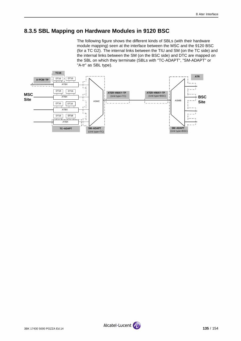
8 Ater Interface
8.3.5 SBL Mapping on Hardware Modules in 9120 BSC
The following figure shows the different kinds of SBLs (with their hardwaremodule mapping) seen at the interface between the MSC and the 9120 BSC(for a TC G2). The internal links between the TIU and SM (on the TC side) andthe internal links between the SM (on the BSC side) and DTC are mapped onthe SBL on which they terminate (SBLs with "TC-ADAPT", "SM-ADAPT" or"A-tr" as SBL type).
MSCSite
BSCSiteASMC ASMB
TC−ADAPT SM−ADAPT SM−ADAPT
A−PCM −TP
DT16
TC16
ATBX
DT16DT16
DT16
ATBX
DT16DT16
DT16
ATBX
ATBX
DT16DT16
ATER−HWAY−TP(Unit type=TC) (Unit type=BSC)
(Unit type=TC) (Unit type=BSC)
ATR
ATER−HWAY−TP
3BK 17430 5000 PGZZA Ed.14 135 / 154

8 Ater Interface
8.4 Numbering Scheme on 9130 BSC Evolution-Ater/Atermux/TCAter/A Interface
8.4.1 Overview
In order to avoid handling large TC configurations and because the 9130BSC Evolution is limited in Erlangs, two kinds of Atermux are available withthe 9130 BSC Evolution:
Atermux from 1 to 30 and 59 to 76 that can be connected to the MFS orTC: E1 Ater CS (Circuit Switch)
Atermux from 31 to 58 that can be connected only to the MFS: E1 Ater
PS (Packet Switch).
This is why the number of Ater-Hway-TP is not the same on the TC side and onthe 9130 BSC Evolution side. The Ater-Hway-TP from 31 to 58 can only beused for GPRS dedicated Atermux.
For a detailed view of the numbering scheme for the 9130 BSC Evolution -Atermux, refer to Figure 8.
8.4.2 Numbering Scheme on 9130 BSC Side
The following table shows the numbering scheme for the 9130 BSC side.
SBL Ater-HW-TP
ETU ECU SSW-HW DTC
Physicalobject
Atermux LIU E1ConcentrationUnit
EthernetSWitch
DigitalController
Numbering 1...76 1...16 1,2 1,2 1...322*
* : DTC: [1..322] [4 x (48 DTC Ater CS + 28 DTC Ater PS + 4 E1 not used)] (CCP) +2 DTCTCH-RM (OMCP: SBLs 305, 306)
136 / 154 3BK 17430 5000 PGZZA Ed.14
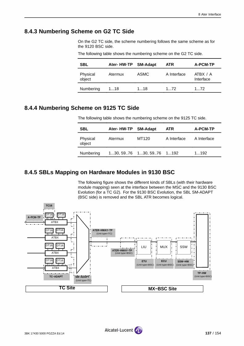
8 Ater Interface
8.4.3 Numbering Scheme on G2 TC Side
On the G2 TC side, the scheme numbering follows the same scheme as forthe 9120 BSC side.
The following table shows the numbering scheme on the G2 TC side.
SBL Ater- HW-TP SM-Adapt ATR A-PCM-TP
Physicalobject
Atermux ASMC A Interface ATBX / AInterface
Numbering 1...18 1...18 1...72 1...72
8.4.4 Numbering Scheme on 9125 TC Side
The following table shows the numbering scheme on the 9125 TC side.
SBL Ater- HW-TP SM-Adapt ATR A-PCM-TP
Physicalobject
Atermux MT120 A Interface A Interface
Numbering 1...30, 59..76 1...30, 59..76 1...192 1...192
8.4.5 SBLs Mapping on Hardware Modules in 9130 BSC
The following figure shows the different kinds of SBLs (with their hardwaremodule mapping) seen at the interface between the MSC and the 9130 BSCEvolution (for a TC G2). For the 9130 BSC Evolution, the SBL SM-ADAPT(BSC side) is removed and the SBL ATR becomes logical.
TC Site MX−BSC Site
TP−HW
(Unit type=BSC)
(Unit type=BSC)
ECU
(Unit type=BSC)
ETU
(Unit type=BSC)
LIU
MUX
ATER−HWAY−TP(Unit type=TC)
SM−ADAPT
(Unit type=TC)
TC−ADAPT
A−PCM−TP
TC16
SSW−HW
(Unit type=BSC)
SSW
DT16 DT16
DT16 DT16
DT16 DT16
DT16 DT16
ATBX
ATBX
ATBX
ATBX
ATER−HWAY−TP
3BK 17430 5000 PGZZA Ed.14 137 / 154
8 Ater Interface
8.5 Signaling on Ater/Atermux Side
8.5.1 Overview
Signaling links (A, Ater and Atermux links) convey information betweendifferent entities:
Signaling System N7 (SS7)SS7 carries the signaling information relating to call control and mobilitymanagement between the BSS and MSC. The signaling is arrangedaccording to the CCITT Recommendations Q.700-714 for the networkprotocol layer and to GSM 08.08 for the GSM application layer.
X.25An X.25 link is set between the 9120 BSC and the OMC_R. Dependingon the BSC position related to the OMC_R, this link can be directlyestablished from the 9120 BSC to the OMC_R via an X.25 network, orcarried up to the TRCU site or the MSC site on the A trunk and then viaan X.25 Network (TS31).
IPThe connection of 9130 BSC Evolution with the OMC-R is based on theIP protocol on both two routes, namely over direct IP network, or overAter and IP network.
GSLThe GSL handles signaling for GPRS paging and for all synchronizationbetween the BSC and the MFS (TS28).
QmuxQmux is always carried in the first nibble of TS 14.
138 / 154 3BK 17430 5000 PGZZA Ed.14

8 Ater Interface
8.5.2 SS7 Signaling Link Code
On the BSC/MSC interface, the Signaling Link Code (SLC) included in theheader (the label) of the Message Transfer Part (MTP) level 3 messages iscoded on 4 bits, with values ranging from 0 to 15.
There are no known rules concerning SLC values. The value 0 has no particularrelevance when compared to the others. When less than 16 SS7 links are usedin a given signaling set, the SLC values in use can be non-consecutive.
The SLC is an interface attribute concerning both the BSS and NSS. It is not aprivate DTC attribute. In principle, the SLC values are determined by a bilateralagreement and assigned to the peer BSC and MSC management entities usingO&M configuration procedures. A SLC value is unique within a BSS.
In terms of SLC value allocation:
The BSC ensures that all SS7 links use different SLC values
For each added SS7, its SLC equals the highest SLC which is not alreadyassociated with an equipped SS7. This algorithm is performed for newly
added SS7 in the increasing order of SS7 SBL numbering (i.e. the new SS7with the lowest SBL number must be processed first, and so on).Such an algorithm is flexible enough to be compatible with any alreadyinstalled configuration. Furthermore, in the case of an MSC which does nothandle SLCs equal to "0", it guarantees that the SS7 which is associatedwith the SLC "0" will be always the 16th (this SS7 must remain "OPR").
The MSC is configured accordingly when the corresponding SS7 is initialized.
A BSC linked to an MSC which does not handle SLCs equal to "0" can handle amaximum of 15 SS7s (instead of the usual 16), however, in such a case, themaximum BSC traffic capacity cannot be achieved.
3BK 17430 5000 PGZZA Ed.14 139 / 154

8 Ater Interface
8.5.3 SS7 Links
The following rules apply:
The SLC is known by the MSC and BSC within 4 bits
SBL numbering corresponds to the DTC numbering which follows Atrunk numbering.
The following table shows SS7, Atermux, DTC and Ater numbering. TheNetwork Location (NAD) is the DTC location in the BSS.
SBL SS7/DTC/Ater Number Atermux
1 1
5 2
9 3
13 4
17 5
21 6
25 7
29 8
33 9
37 10
41 11
45 12
49 13
53 14
57 15
61 16
Table 29: SS7, Atermux, DTC and Ater Numbering
There are two operation modes of a SS7 link:
Low speed (64 kbit/s) [LSL]
High speed (1.984 Mbit/s) [HSL].
140 / 154 3BK 17430 5000 PGZZA Ed.14
8 Ater Interface
LSL/HSL
The total number of LSL+HSL is a maximum of 48
The maximum number of HSL is 8
To avoid excessive SS7 dimensioning, the number of BSS using HSL on aTC is limited to 4
The maximum signalling load is:
200 Erlang per LSL
4800 Erlang per 2 HSL links
Total 27200 Erlang.
The transmission network between the 9130 BSC and the MSC ensures theframe integrity for timeslots 1 to 3. HSL links are between the BSC and MSC.
The mixed mode (LSL+HSL) is not allowed.
Any Atermux defined in the BSC configuration can be used to support HSL, butthe BSC checks that these two Atermux:
Do not carry Qmux
Do not carry IP over Ater
Are configured for CS traffic only
Are on two different LIU boards.
3BK 17430 5000 PGZZA Ed.14 141 / 154

8 Ater Interface
8.6 GPRS and GSM Traffic on Atermux versus 9120 BSC
8.6.1 Overview
There are two types of Ater Mux links to the MFS:
Dedicated
Mixed.
CS refers to circuit switched GSM traffic and PS refers to packet switchedGPRS traffic.
For dedicated GPRS Atermux links, SM (TC site) and associated TRCUs arenot equipped. SS7 TS is not used, with or without GSL LAPD.
Note that in the MFS to BSC direction, on the Atermux supporting the "Alarmoctet" (or TS0 information), the MFS will force a fixed pattern that is used atthe BSC site.
For mixed GPRS/CS Atermux links, the traffic TS can be used 12.5% or 25% or50% or 75% or 100% for GPRS, with or without GSL LAPD. SS7 can also becarried on the corresponding Ater Mux (up to 16).
On the Atermux, channels located within the TS also containing the Qmuxcannot be used for GPRS.
X.25 links can optionally be carried on the first 2 Atermux in the 9120 BSC.
MLPPP can optionally be carried on the first 16 Ater Mux for 9130 BSC.
Qmux links are always carried on the first 2 Atermux from the Ater Mux cluster(group of 6 Ater Mux).
If there is an SS7 link, then the Atermux can carry either CS or a mixture ofPS and CS traffic.
142 / 154 3BK 17430 5000 PGZZA Ed.14

8 Ater Interface
8.6.2 Hole Management in G2 TC
When GPRS is introduced in a BSS and when an Atermux is fully dedicated tothe GPRS, the related ASMC in the TC rack and TRCU are not used, becausethe Gb does not go through the TC.
When an Atermux dedicated to GSM traffic is added to the BSS later, theASMC in the TC rack and the TRCU which were not used, remain unused andthe added Atermux is connected to the following ASMC in the TC rack. Thiscan be considered as a hole in the TC rack configuration where an ASMCwill be never used.
This is shown in the following example:
First state:
Atermux is used for GSM traffic
G2 TC rack filled with 4 Atermux.
Second state GPRS introduction:
With dedicated Ater for the Gb interface
Atermux 5 and 6 are put as NEQ for G2 TC equipment.
Third state GSM traffic increase:
Need additional Atermux (TC boards)
A new rack is needed because Atermux 5 and 6 are NEQ.
This situation is not applicable to 9125 TC, because the operator configures theMT120 to Ater Mux mapping with 9125 TC terminal.
8.6.3 Sharing Atermux PCM Links
The following PCM rules apply:
X is the number of Atermux between the BSC and the GPU
Y is the number of Atermux between the GPU and the TC (mixed Ater Mux)
Z is the number of Gb Interfaces between the GPU and SGSN
X+Y+Z <= 16 for legacy, 12/14/16 for 9130 MFS depending on configuration
When the Atermux transports mixed traffic: X=Y
There are a maximum 12/14/16 PCM links at the GPU for traffic. For 9135MFS, in the case of ‘Fixed Synchronization Sources’ feature use, only 8 PCMlinks can be used for traffic.
The minimum number of GPU-TC and GPU-SGSN links (Y+Z) is 1. Themaximum number of BSC-GPU links is 13, and the maximum number ofBSC-MFS links depends on the BSC configuration. It is also possible to haveone complete PCM (X) with GPRS and a direct connection to SGSN (thenY can be null). Z also can be null.
3BK 17430 5000 PGZZA Ed.14 143 / 154
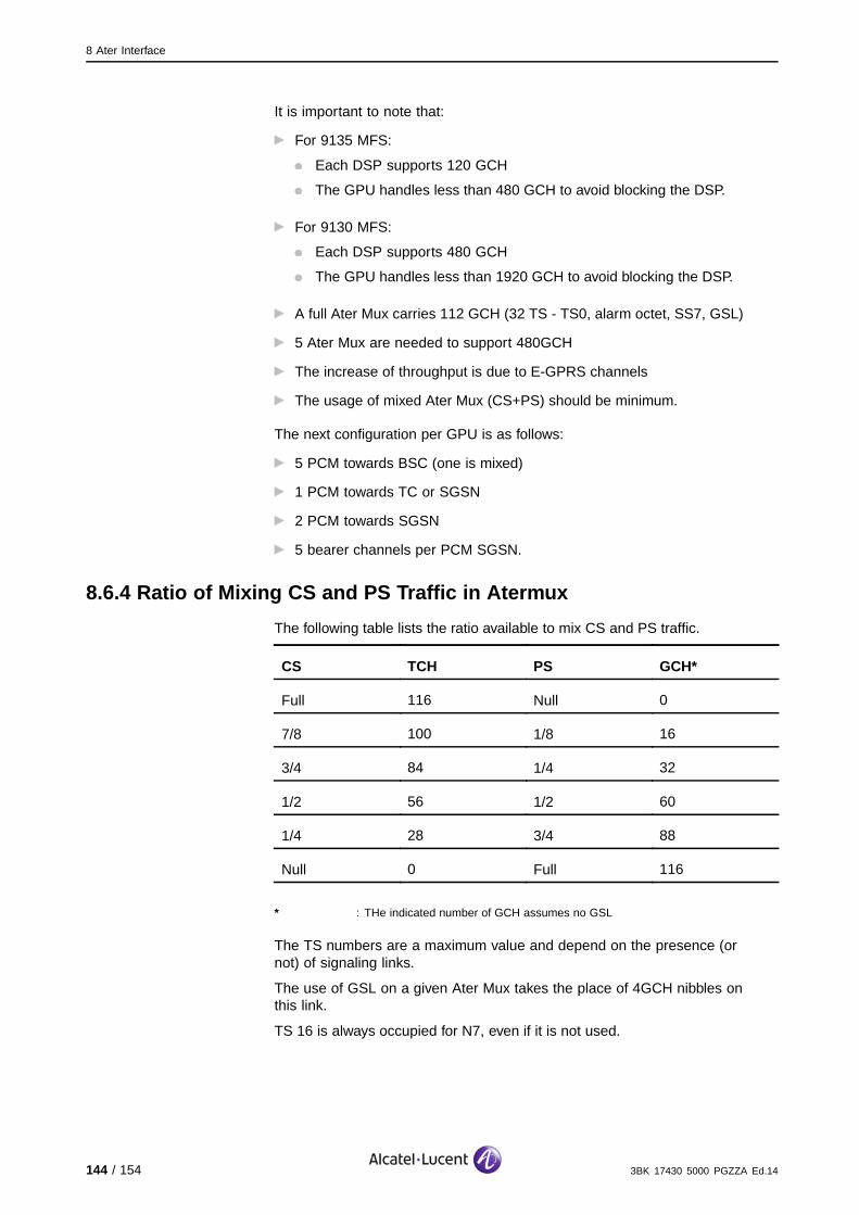
8 Ater Interface
It is important to note that:
For 9135 MFS:
Each DSP supports 120 GCH
The GPU handles less than 480 GCH to avoid blocking the DSP.
For 9130 MFS:
Each DSP supports 480 GCH
The GPU handles less than 1920 GCH to avoid blocking the DSP.
A full Ater Mux carries 112 GCH (32 TS - TS0, alarm octet, SS7, GSL)
5 Ater Mux are needed to support 480GCH
The increase of throughput is due to E-GPRS channels
The usage of mixed Ater Mux (CS+PS) should be minimum.
The next configuration per GPU is as follows:
5 PCM towards BSC (one is mixed)
1 PCM towards TC or SGSN
2 PCM towards SGSN
5 bearer channels per PCM SGSN.
8.6.4 Ratio of Mixing CS and PS Traffic in Atermux
The following table lists the ratio available to mix CS and PS traffic.
CS TCH PS GCH*
Full 116 Null 0
7/8 100 1/8 16
3/4 84 1/4 32
1/2 56 1/2 60
1/4 28 3/4 88
Null 0 Full 116
* : THe indicated number of GCH assumes no GSL
The TS numbers are a maximum value and depend on the presence (ornot) of signaling links.
The use of GSL on a given Ater Mux takes the place of 4GCH nibbles onthis link.
TS 16 is always occupied for N7, even if it is not used.
144 / 154 3BK 17430 5000 PGZZA Ed.14

8 Ater Interface
8.7 Ater Satellite LinksThe Ater interfaces are designed to use terrestrial transmission links.
The operator can configure the way an Ater is carried, either via a terrestriallink, or via satellite.
When the link is via satellite, the system applies different parameters to wait foracknowledgement, in order to repeat the frames.
Satellite links cannot be used at the same time on both the Ater interface andthe Abis interface (see Abis Satellite Links (Section 7.8)).
The following configuration rules apply:
On the Ater interface, all the links are handled in the same way. The satellitelink can be installed either on the Ater (between the BSC and the TC), or
on the A interface (between the TC and the MSC). As the latter case iscomparatively rare, the process is referred to as Ater. In the case where
the satellite link is on the A interface, the modification of the transmissionsupervision timer is not useful but is implemented.
In the case where only a part of the TS are routed via the satellite, at least
Qmux, X25/MLPPP (if via A interface) must be routed. Non-routed channelsmust be blocked either from the MSC or from the OMC-R.
If only one link is forwarded, there is no redundancy on SS7, X25/MLPPP, or
Qmux. This configuration is not recommended but it does work.
When A interfaces or Ater interfaces are routed via satellite, the SS7 areconfigured to use Preventive Cyclic Retransmission (PCR).
LCS is supported with Ater satellites.
3BK 17430 5000 PGZZA Ed.14 145 / 154

8 Ater Interface
The following conditions must be fulfilled if Ater satellites support GPRS:
Increase T200_GSL from 1 sec to 2 sec (in the customer BUL file) in
the MFS
If needed, increase K_GSL from 16 to 32 (in the customer BUL file) inthe MFS
Add GSL links (see the following table).
Value of Nb_Msg_BSCGP(High/Medium/Low factor)
Nb of GSL links(K_GSL = 16)
Nb of GSL links(K_GSL = 32)
0 < <= 32 1
232< <=64
1
64< <=96 3
496< <=128
2
128< <=192 3
192< <=256 4
where Nb_Msg_BSCGP is the number of messages sent by the MFS on theBSCGP interface.
146 / 154 3BK 17430 5000 PGZZA Ed.14

9 GB Interface
9 GB Interface
This section describes the GB interface, and corresponding features andfunctions.
3BK 17430 5000 PGZZA Ed.14 147 / 154

9 GB Interface
9.1 Gb TopologyThe interface between the MFS and the SGSN is referred to as the Gbinterface. It is supported by 2Mbit/s PCM links of 32 TS at 64Kbit/s.
There are three possible ways to connect the MFS to SGSN:
Via Gb links directly to SGSN
OMC
BSC TC
MSC
GbInterface
MFS
SGSN
MFS−TC InterfaceMixed CS/GPRSCS TS
GPRS TSConversionof Protocol
SM
Atermux Interface
Frame Relay/IPA
Interface
Atermux Interface
Figure 17: Gb Link Directly to SGSN
Via Atermux links and Gb links through the TC and the MSC, therefore CSTS are routed transparently to the MSC across the MFS. GPRS TS are
transparent in the TC. GPRS TS are converted to Gb TS in the MFS. TheTC transmission is updated in this case, so that TC is ready when Gb goes
to SGSN through the TC (this is known as “TC transparency").
BSC TC
MSC
GbInterface
MFS
SGSN
MFS−TC InterfaceMixed CS/GPRS
AtermuxCS TS
GPRS TSConversionof Protocol
Frame Relay
OMC
SM
Figure 18: Gb Link through the TC and MSC
148 / 154 3BK 17430 5000 PGZZA Ed.14

9 GB Interface
Via Gb links from the MFS to SGSN through the MSC, whereby a PCM isdedicated to Gb interface and GPRS TS are converted to Gb TS in the MFS.
OMC
BSC TC
MSC
MFS
SGSN
MFS−TC InterfaceMixed CS/GPRSCS TS
GPRS TSConversionof Protocol
SM
Atermux Interface
AInterface
Atermux Interface
Frame Relay
GbInterface
Figure 19: Gb Link through the MSC
9.2 Gb ConfigurationThe BSSGP, Network Service (NS) and physical layer protocols define the Gbinterface. The BSSGP manages GB Interface and Virtual Connections (BVC)identified by their BVCI.
There are three types of BVC:
BVC-PTPVirtual circuit Point to Point assigned for the GPRS traffic of one cell: BVCI>1
BVC-PTMVirtual circuit Point to Multi-point (not used in the BSS): BVCI=1
BVC-SIGSignaling of all BVC-TTP: BVCI=0.
The NS depends on the Intermediate Network Transmission (ITN), in two parts:
With Frame Relay:The Sub-Network Service (SNS) depends on the ITN. At present, the ITNused is Frame Relay. The SNS handles the Permanent Virtual Connections(PVC). Each PVC is associated with one NS-VC. The Data Link ConnectionIdentifier (DLCI) is used to number the PVC. The DLCI=0 is not PVC but isused for signaling on the Bearer Channel BC0.
Without Frame Relay:The Network Service Control (NSC) is independent from the ITN. The NSChandles the NS-VC virtual connections end to end for the MFS-SGSN. AnNetwork Service Element (NSE) is a group of NS-VC.
3BK 17430 5000 PGZZA Ed.14 149 / 154
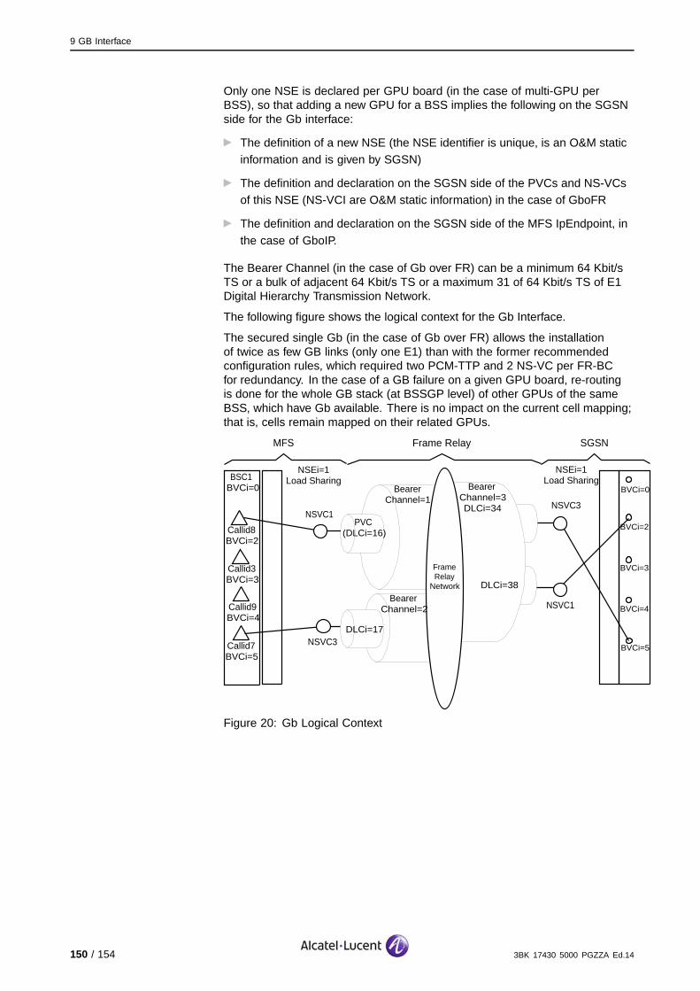
9 GB Interface
Only one NSE is declared per GPU board (in the case of multi-GPU perBSS), so that adding a new GPU for a BSS implies the following on the SGSNside for the Gb interface:
The definition of a new NSE (the NSE identifier is unique, is an O&M staticinformation and is given by SGSN)
The definition and declaration on the SGSN side of the PVCs and NS-VCsof this NSE (NS-VCI are O&M static information) in the case of GboFR
The definition and declaration on the SGSN side of the MFS IpEndpoint, in
the case of GboIP.
The Bearer Channel (in the case of Gb over FR) can be a minimum 64 Kbit/sTS or a bulk of adjacent 64 Kbit/s TS or a maximum 31 of 64 Kbit/s TS of E1Digital Hierarchy Transmission Network.
The following figure shows the logical context for the Gb Interface.
The secured single Gb (in the case of Gb over FR) allows the installationof twice as few GB links (only one E1) than with the former recommendedconfiguration rules, which required two PCM-TTP and 2 NS-VC per FR-BCfor redundancy. In the case of a GB failure on a given GPU board, re-routingis done for the whole GB stack (at BSSGP level) of other GPUs of the sameBSS, which have Gb available. There is no impact on the current cell mapping;that is, cells remain mapped on their related GPUs.
FrameRelay
Network
MFS Frame Relay SGSN
BSC1BVCi=0
Callid8BVCi=2
Callid3BVCi=3
Callid9BVCi=4
Callid7BVCi=5
NSEi=1Load Sharing
NSEi=1Load Sharing
NSVC1
NSVC3
PVC(DLCi=16)
BearerChannel=1
BearerChannel=2
BearerChannel=3DLCi=34
DLCi=38
NSVC3
NSVC1
BVCi=0
DLCi=17
BVCi=2
BVCi=3
BVCi=4
BVCi=5
Figure 20: Gb Logical Context
150 / 154 3BK 17430 5000 PGZZA Ed.14

10 CBC Connection, SMSCB Phase 2+
10 CBC Connection, SMSCB Phase 2+
This section describes the GSM Short Message Service Cell Broadcast(SMSCB) features and functions.
3BK 17430 5000 PGZZA Ed.14 151 / 154

10 CBC Connection, SMSCB Phase 2+
10.1 OverviewThe GSM SMSCB feature allows the distribution of messages from an SMSCBcentre (CBC) to a mobile station listening in idle mode to a general broadcastchannel called the CBCH.
10.2 GSM Cell Broadcast ApplicationsThere are two types of applications for the GSM Cell Broadcast feature:
Applications where the information broadcast relates more or less to mobilestation operation in the network. This type of application is driven directly
by the network/operator. Applications such as home zone indication,charging rate indication or the network condition indication are value added
features for the operator.
Applications where the operator offers the Cell Broadcast facility for useby entities external to the GSM Network. Applications such as road traffic
information, public safety, and advertisements can be a source of additionalrevenue for the operator.
Note that these types of applications can coexist.
152 / 154 3BK 17430 5000 PGZZA Ed.14

10 CBC Connection, SMSCB Phase 2+
10.3 Solutions
10.3.1 9120 BSC Solutions
For the X25 CBC-BSC connection (which differs from the OMC-R connection,but which must be configured in the same way), several alternative solutionsexist:
PSDN
Connection via Ater, extraction at TRCU
Connection via Ater, extraction at MSC.
The solution by default is PSDN. A BSC can be connected to one CBCmaximum.
10.3.1.1 CBC-BSC Interconnection via PSDNNormally, an redundant solution is used for CBC-BSC interconnection. Twolinks can be provided towards the CBC:
Primary link
Secondary link (backup link).
The secondary link is optional. This redundant link, if it exists, is only used if thecommunication with the CBC cannot be achieved using the primary link.
The following figure shows a CBC-BSC interconnection via PSDN.
BTS1
BTS2
BTS3
BSC1
BSC2
BSC3
Abis Ater Atermux Ater A
PSDN
OMC CBC
SM SM TRCU
MSC1
MSC2
MSC3
SMCB Path
Figure 21: CBC-BSC Interconnection via PSDN
3BK 17430 5000 PGZZA Ed.14 153 / 154

10 CBC Connection, SMSCB Phase 2+
10.3.1.2 CBC-BSC Interconnection via MSCThis solution exists for a private operator who pays a high price for connectionsor for export markets where there are no X.25 networks.
It is preferable that the CBC and OMC-R are collocated (connected to the sameMSC), in order to avoid technical complications including:
The redundancy of the external equipment (router) and transmission lines
(LL)
Switchovers
O&M to manage for external equipment (managed generally by proprietary
or SNMP stacks which prevent an integrated Network Management).
The following figure shows CBC-BSC interconnection via the MSC.
MSC1
MSC2
MSC3
TRCU
BSC1
BSC2
BSC3
BTS1
BTS2
BTS3
Abis A
Router
CBC
SM
SM
Atermux
Ater
Ater
: SMCB Path
OMC
Figure 22: CBC-BSCs Interconnection via the MSC
For more information, refer to BSS Routing Configurations.
10.3.2 9130 BSC Evolution Solutions
The X25 protocol is still supported for the CBC interface, however directconnection of the CBC from the BSC site is no longer supported. The CBCconnection is made through the X25 over Ater at the TC or MSC site. Accordingto the 3GPP definition, the SMS-CB service maintains the X.25 connection.Therfore, the 9130 BSC Evolution keeps transferring X.25 packets to CBC overAter on the TC/MSC site or directly over the IP network on the 9130 BSCEvolution site. (ML-) PPP or 802.3A/B is used on the 9130 BSC Evolution siteto carry the X.25 packets.
For more information, refer to BSS Routing Configurations.
154 / 154 3BK 17430 5000 PGZZA Ed.14