10/9/2014LCWS14 : Accelerator : ADI / M. Woodley1 / 14 Status of ILC Decks.
14
10/9/2014 LCWS14 : Accelerator : ADI / M. Woodley 1 / 14 Status of ILC Decks
-
Upload
imogen-flowers -
Category
Documents
-
view
214 -
download
0
Transcript of 10/9/2014LCWS14 : Accelerator : ADI / M. Woodley1 / 14 Status of ILC Decks.

LCWS14 : Accelerator : ADI / M. Woodley10/9/2014 1 / 14
Status of ILC Decks
10/9/2014 LCWS14 : Accelerator : ADI / M. Woodley 2 / 14
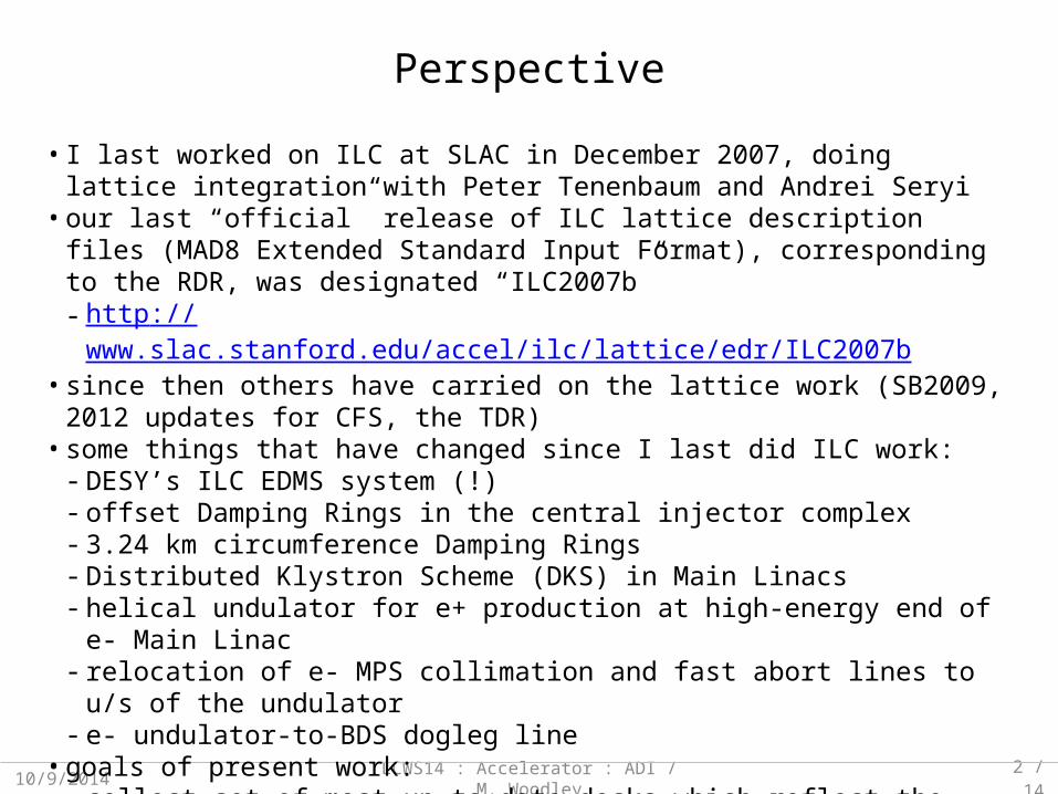
• I last worked on ILC at SLAC in December 2007, doing lattice integration with Peter Tenenbaum and Andrei Seryi• our last “official” release of ILC lattice description files (MAD8 Extended Standard Input
Format), corresponding to the RDR, was designated “ILC2007b”- http://www.slac.stanford.edu/accel/ilc/lattice/edr/ILC2007b• since then others have carried on the lattice work (SB2009, 2012 updates for CFS, the
TDR)• some things that have changed since I last did ILC work:
- DESY’s ILC EDMS system (!)- offset Damping Rings in the central injector complex- 3.24 km circumference Damping Rings- Distributed Klystron Scheme (DKS) in Main Linacs- helical undulator for e+ production at high-energy end of e- Main Linac- relocation of e- MPS collimation and fast abort lines to u/s of the undulator- e- undulator-to-BDS dogleg line• goals of present work:
- collect set of most up-to-date decks which reflect the lattice described in the TDR- integrate deck sets for major subsystems (eSource, pSource, DRs, ELET, PLET)- reproduce TDR CFS geometry (EDMS Treaty Point coordinates)
Perspective
10/9/2014 LCWS14 : Accelerator : ADI / M. Woodley 3 / 14
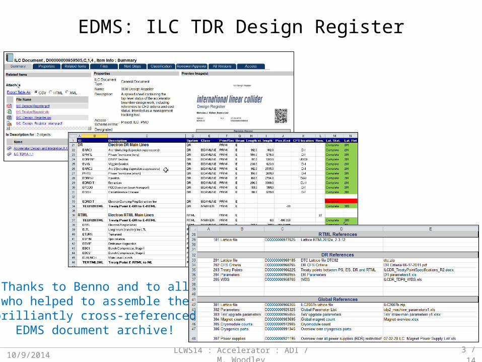
EDMS: ILC TDR Design Register
Thanks to Benno and to allwho helped to assemble thebrilliantly cross-referencedEDMS document archive!

10/9/2014 LCWS14 : Accelerator : ADI / M. Woodley 4 / 14
EDMS: Treaty Point Definitions
Absolutely essential!

10/9/2014 LCWS14 : Accelerator : ADI / M. Woodley 5 / 14
subsystems source doc / file comments
ESOURCE EDMS D*0976695,B,1,1ES2012a.zip
Design registry (exit of bunchers to end of ELTR)
EDR / PDR EDMS D*0960185,G,1,1dtc04.zip
DTC04 lattice (3238.7 m DR circumference)
ERTML / PRTML EDMS D*0977625,B,1,1RTML2012a.zip
KCS lattice
EML / PML DESYsvn
ilclattice-ml-dks_BL20120608
.r234.tar.gz
A. Valishev / B. List DKS lattice:• svn branch: ILC2012dks_ML_3RFU_VK201206• svn folder: ml-dks-BL20120608
EBDS / PBDS EDMS D*0972985,B,1,2BDS2012b.zip
Glen and Edu are updating the BDS Final Focus and dump line lattices
PSOURCE EDMS D*0977535,B,1,1ps-lattice-2012a.zip
W. Liu / W. Gai TDR lattice• described in IPAC2012 paper TUPPR041
Deck Files Obtained and Integrated so far

10/9/2014 LCWS14 : Accelerator : ADI / M. Woodley 6 / 14
subsystems comments
EDREXT / PDREXTEDRINJ / PDRINJ
created by MDW from:• I. Reichel documents• TDR text• Treaty Point coordinate definitions
PTURN small geometry changes in vertical dogleg (no matching)
ELTL / PLTL converted by MDW for DKS (no matching):• lengthen ELTL FODO cell: 36.016 m to 36.141 m (ΔL = 47.348 m)• lengthen PLTL FODO cell: 35.912 m to 36.041 m (ΔL = 44.848 m)
UPT created by MDW (August 2014):• END_EUND to target drift: L= 372.044 m
EBSY1 / EBSY2PBSY1 / PBSY2
Redefinition errors discovered during “deck integration”:• polarimeter chicanes were copied from *BSY2 to *BSY1 as separate laserwire detection chicanes• names of elements (bends and drifts) were not changed• names of parameters that defined bend and drift lengths were not changed• values of parameters that defined bend and drift lengths were changed in *BSY1 files• when *BSY1 file is loaded, LW chicane is 45.1 m long• when *BSY2 file is loaded, LW chicane is redefined to be 76.9 m long (ΔL = 31.8 m)• TDR CFS coordinates include BSY LW chicanes that are each 31.8 m too long
PBDS is 0.95 m shorter than EBDS due to rematching between PBSY and PFFS• TDR CFS coordinates include shorter PBDS
Recreating the TDR CFS geometry

10/9/2014 LCWS14 : Accelerator : ADI / M. Woodley 7 / 14
Damping Rings: Injection / Extraction
From the TDR (v3.II, section 6.9):

-100 -80 -60 -40 -20 094
95
96
97
98
99
100
Z (m)
X (
m)
10/9/2014 LCWS14 : Accelerator : ADI / M. Woodley 8 / 14
33 kickersΣθ = 1.2 mrad
septum 1 & 2BL = 18.1 kG-m
bendBL = 21.9 kG
84 mm
centerof PDRINJ/EXTstraight
kicker #33exit face
septum 1exit face
TPS2DR
TPS2DR X = 94.410 mY = 0.350 mZ = -112.103 mθ = 0.240 rad
Positron Damping Ring (DTC04): Injection

10/9/2014 LCWS14 : Accelerator : ADI / M. Woodley 9 / 14
0 10 20 30 40 50 60 70 80 90 100 11094
95
96
97
98
99
100
Z (m)
X (
m)
33 kickersΣθ = 0.6 mrad
septum 1 & 2BL = 18.1 kG-m
bendBL = 21.9 kG
42 mm
centerof PDRINJ/EXTstraight
kicker #1entrance
face
septum 1entrance
face
TPDR2RTML
TPDR2RTML X = 94.410 mY = 0.350 mZ = 106.988 mθ = -0.240 rad
Positron Damping Ring (DTC04): Extraction

-1.5 -1 -0.5 0 0.5 1 1.5
x 104
0
100
200
300
400
500
600
ILC2014a : SURVEY coordinates (plan view)
Z (m)
X (
m)
10/9/2014 LCWS14 : Accelerator : ADI / M. Woodley 10 / 14
DR INJ/EXT straight centerline X = 100.000 mYe+ = 0.350 mYe- = 1.650 mZ = 0.000 mθe+ = 0.000 radθe- = π rad
IP X = 0.000 mY = 0.000 mZ = 0.000 mθe+ = π + 0.007 radθe- = -0.007 rad
e- systems e+ systems
eSource + EDR + ELET + UPT + pSource + PDR + PLET
undulatorphotons
-3000 -2000 -1000 0 1000 2000 3000
0
10
20
30
40
50
60
70
80
90
100
ILC2014a : SURVEY coordinates (plan view)
Z (m)
X (
m)
10/9/2014 LCWS14 : Accelerator : ADI / M. Woodley 11 / 14
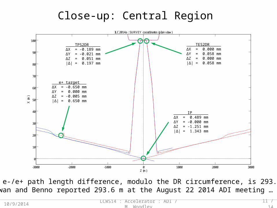
e+ target ΔX = -0.650 mmΔY = 0.000 mmΔZ = -0.005 mm|Δ| = 0.650 mm
TPS2DR ΔX = -0.189 mmΔY = -0.021 mmΔZ = 0.051 mm|Δ| = 0.197 mm
IP ΔX = 0.489 mmΔY = -0.000 mmΔZ = -1.251 mm|Δ| = 1.343 mm
Close-up: Central Region
Note: e-/e+ path length difference, modulo the DR circumference, is 293.141 m(Ewan and Benno reported 293.6 m at the August 22 2014 ADI meeting … )
TES2DR ΔX = 0.000 mmΔY = 0.058 mmΔZ = 0.000 mm|Δ| = 0.058 mm
10/9/2014 LCWS14 : Accelerator : ADI / M. Woodley 12 / 14
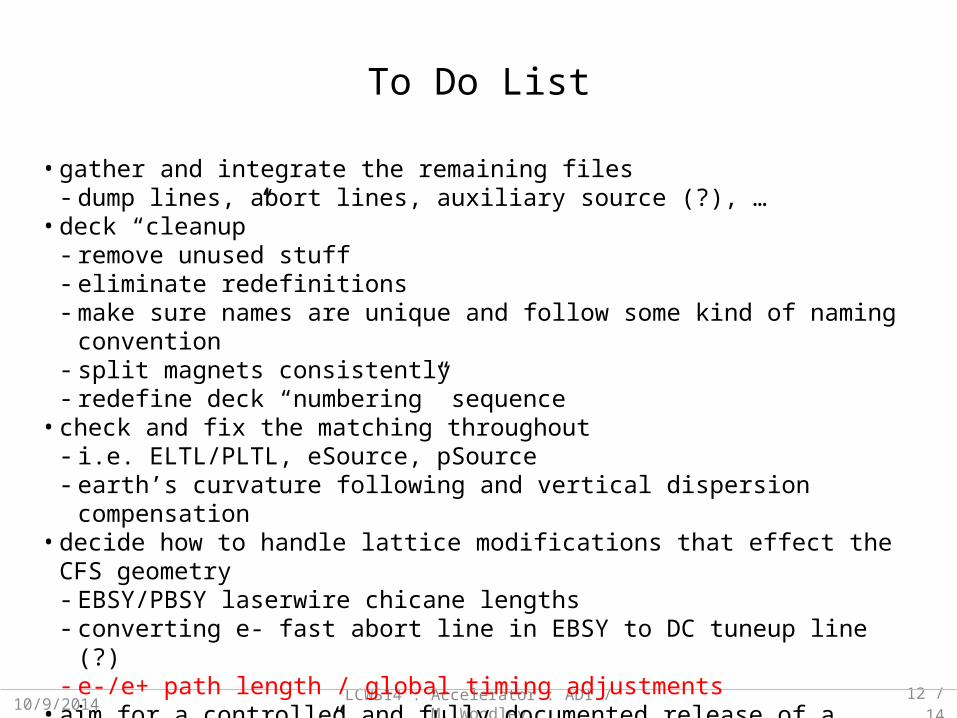
To Do List
• gather and integrate the remaining files- dump lines, abort lines, auxiliary source (?), …• deck “cleanup”
- remove unused stuff- eliminate redefinitions- make sure names are unique and follow some kind of naming convention- split magnets consistently- redefine deck “numbering” sequence• check and fix the matching throughout
- i.e. ELTL/PLTL, eSource, pSource- earth’s curvature following and vertical dispersion compensation• decide how to handle lattice modifications that effect the CFS geometry
- EBSY/PBSY laserwire chicane lengths- converting e- fast abort line in EBSY to DC tuneup line (?)- e-/e+ path length / global timing adjustments• aim for a controlled and fully documented release of a complete “ILC2014a” deck set

10/9/2014 LCWS14 : Accelerator : ADI / M. Woodley 13 / 14
Conclusions and Outlook
• using DESY EDMS system and SVN repository, MAD8 input files corresponding to the TDR for the major accelerator systems of ILC have been gathered and (partially) integrated- eSource, pSource, DRs, ELET, PLET• the geometry of these systems has been verified to match the current CFS layout (sub-
millimeter errors at Treaty Points)• re-matching (Twiss) has been started … I’m presently working on the Source systems
- LTRs need work• after re-matching comes “deck cleanup” and standardization• then comes documentation• I estimate approximately 4 weeks of full-time work remains to be done to complete a
packaged set of files (similar to ILC2007b) that can be released to EDMS, so an “ILC2014a” release in calendar 2014 seems possible … depending on funding and other commitments (i.e. LCLS-II, FACET, FACET-II, … )
LCWS14 : Accelerator : ADI / M. Woodley10/9/2014 14/14
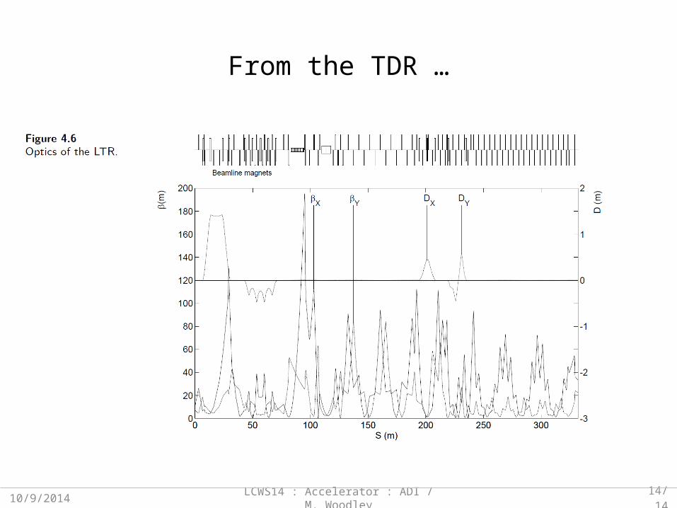
From the TDR …