ILC overview
41
ILC overview 1 S. Michizono and A. Yamamoto (LCC/ILC/KEK) ALCW-2018, Plenary 2018-5-31b 2018/5/31
Transcript of ILC overview
ILC overview
1
S. Michizono and A. Yamamoto
(LCC/ILC/KEK)
ALCW-2018, Plenary
2018-5-31b
2018/5/31
Outline
2018/5/31 2
Introduction
ILC-250 overview
Nano-beam and SRF technologies advanced
Progress in cost-reduction R&D
Summary
The progress in ALCW-2018 to be summarized by B. List, in the plenary, tomorrow.
Physics WG
TDR ValidationWG
Organized
in 2014-15 & 2018
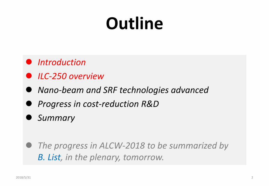
Organized in 2014 ~ current
MEXT
Commissioned Surveyby NRI (2014-17)
ILC Study Coordination by MEXT
• Physics WG, and TDR Validation WG re-organized to evaluate ILC-250GeV.
Human Resource WG
1) WW Research trend (FY14)
2) Technology issues (FY15)
3) Large Int’l project (FY16)
4) Risk/safety issues (FY17)
Organization &Manage.WG
Organized
in 2014-15 & 2018
Organized
in 2017
Organized
in 2015 -16
SCJ
ILC Adv. Panel
Today! S. Michizono,
2014 2018
SCJ, MEXT
WGs
IAP
2018/5/31 3
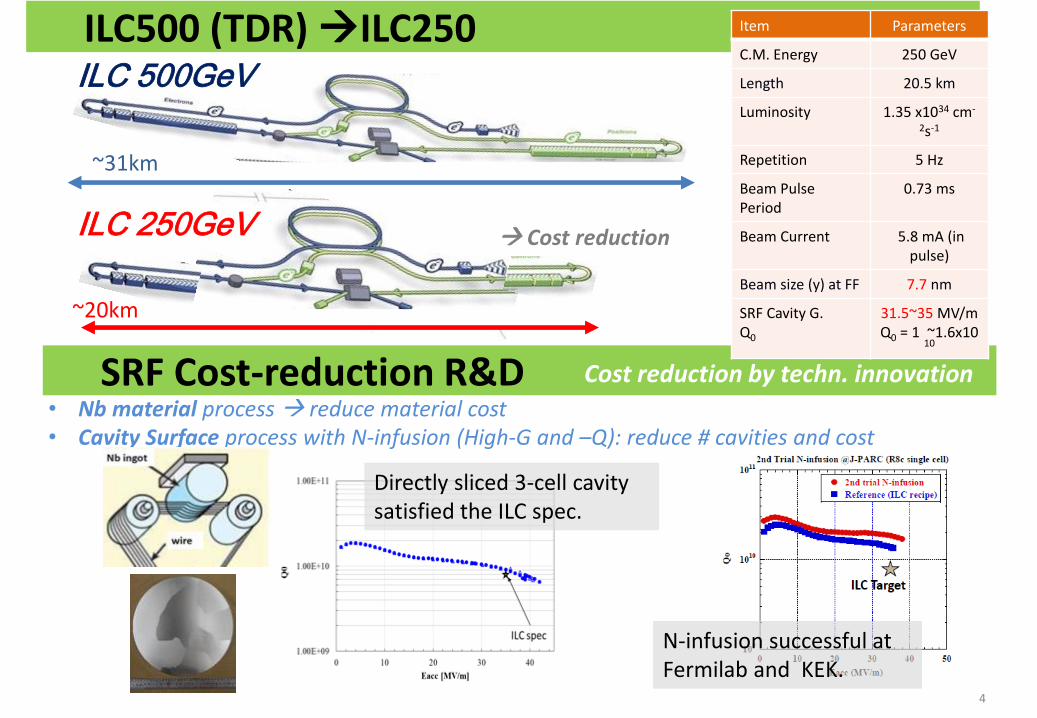
~31km
4
~20km
ILC 500GeV
ILC 250GeV
ILC500 (TDR) ILC250
Cost reduction
SRF Cost-reduction R&D Cost reduction by techn. innovation
• Nb material process reduce material cost • Cavity Surface process with N-infusion (High-G and –Q): reduce # cavities and cost
Item Parameters
C.M. Energy 250 GeV
Length 20.5 km
Luminosity 1.35 x1034 cm-
2s-1
Repetition 5 Hz
Beam Pulse Period
0.73 ms
Beam Current 5.8 mA (in pulse)
Beam size (y) at FF 7.7 nm
SRF Cavity G. Q0
31.5~35 MV/mQ0 = 1 ~1.6x10
10
Directly sliced 3-cell cavity satisfied the ILC spec.
N-infusion successful at Fermilab and KEK.

5
ILC-500 (TDR) ILC250
Collision E.
[GeV]
Tunnel Space [GeV]
Value Total(MILCU in 2012)
Reduction
[%]
TDR 250/250 500 7,980 0
TDR update 250/250 500 7,950 -0.4
Option A 125/125 250 5,260 -34
Option A’(w/ R&D)
125/125 2504,780
w/ R&D success
-40
TDR update:
Options A, A’: 250 GeV
Damping Rings
Turnaround & Bunch compressors
2018/5/31
https://arxiv.org/abs/1711.00568
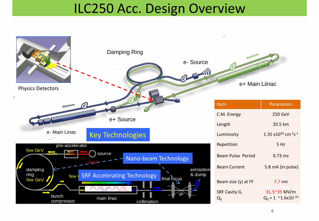
ILC250 Acc. Design Overview
6
e- Source
e+ Main Liinac
e+ Source
e- Main Linac
main linacbunchcompressor
dampingring
source
pre-accelerator
collimation
final focus
IP
extraction& dump
KeV
few GeV
few GeVfew GeV
250-500 GeV
Nano-beam Technology
SRF Accelerating Technology
Key Technologies
Physics Detectors
Damping Ring
Item Parameters
C.M. Energy 250 GeV
Length 20.5 km
Luminosity 1.35 x1034 cm-2s-1
Repetition 5 Hz
Beam Pulse Period 0.73 ms
Beam Current 5.8 mA (in pulse)
Beam size (y) at FF 7.7 nm
SRF Cavity G. Q0
31.5~35 MV/mQ0 = 1 ~1.6x10 10
Outline
2018/5/31 7
Introduction
ILC-250 overview
Nano-beam and SRF technologies advanced
Progress in cost-reduction R&D
Summary
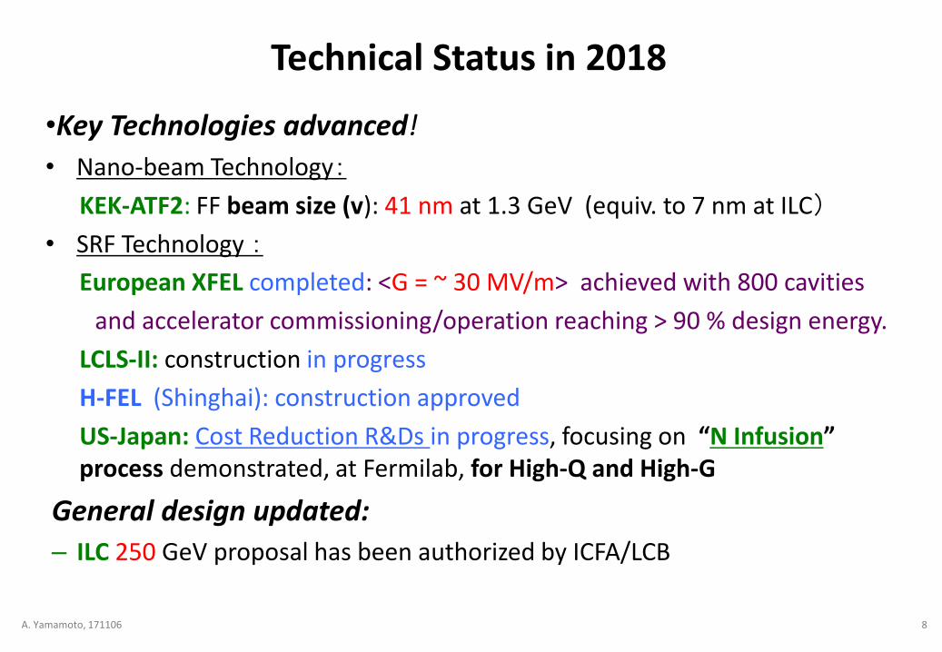
•Key Technologies advanced!
• Nano-beam Technology:
KEK-ATF2: FF beam size (v): 41 nm at 1.3 GeV (equiv. to 7 nm at ILC)
• SRF Technology :
European XFEL completed: <G = ~ 30 MV/m> achieved with 800 cavities
and accelerator commissioning/operation reaching > 90 % design energy.
LCLS-II: construction in progress
H-FEL (Shinghai): construction approved
US-Japan: Cost Reduction R&Ds in progress, focusing on “N Infusion” process demonstrated, at Fermilab, for High-Q and High-G
General design updated:
– ILC 250 GeV proposal has been authorized by ICFA/LCB
Technical Status in 2018
A. Yamamoto, 171106 8
Layout of ILC
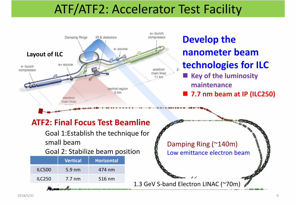
Develop the nanometer beam technologies for ILC Key of the luminosity
maintenance 7.7 nm beam at IP (ILC250)
ATF/ATF2: Accelerator Test Facility
1.3 GeV S-band Electron LINAC (~70m)
Damping Ring (~140m)Low emittance electron beam
ATF2: Final Focus Test BeamlineGoal 1:Establish the technique for small beam Goal 2: Stabilize beam position
9
Vertical Horizontal
ILC500 5.9 nm 474 nm
ILC250 7.7 nm 516 nm
2018/5/31
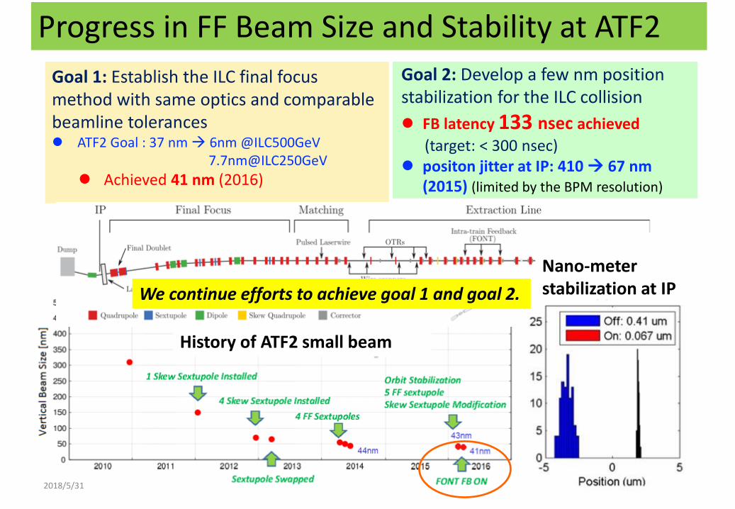
Goal 1: Establish the ILC final focus method with same optics and comparable beamline tolerances ATF2 Goal : 37 nm 6nm @ILC500GeV
7.7nm@ILC250GeV
Achieved 41 nm (2016)
Progress in FF Beam Size and Stability at ATF2
11
Goal 2: Develop a few nm position stabilization for the ILC collision
FB latency 133 nsec achieved
(target: < 300 nsec) positon jitter at IP: 410 67 nm
(2015) (limited by the BPM resolution)
Nano-meter stabilization at IP
History of ATF2 small beam
We continue efforts to achieve goal 1 and goal 2.
2018/5/31
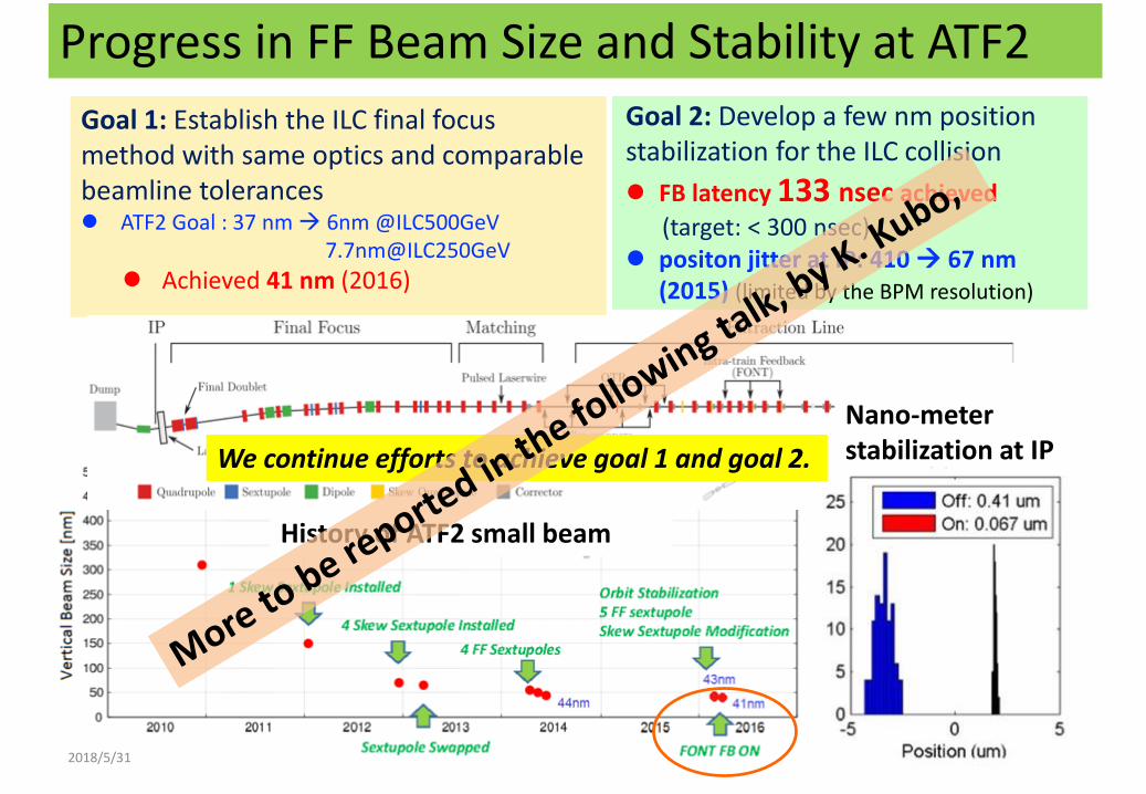
Goal 1: Establish the ILC final focus method with same optics and comparable beamline tolerances ATF2 Goal : 37 nm 6nm @ILC500GeV
7.7nm@ILC250GeV
Achieved 41 nm (2016)
Progress in FF Beam Size and Stability at ATF2
12
Goal 2: Develop a few nm position stabilization for the ILC collision
FB latency 133 nsec achieved
(target: < 300 nsec) positon jitter at IP: 410 67 nm
(2015) (limited by the BPM resolution)
Nano-meter stabilization at IP
History of ATF2 small beam
We continue efforts to achieve goal 1 and goal 2.
2018/5/31
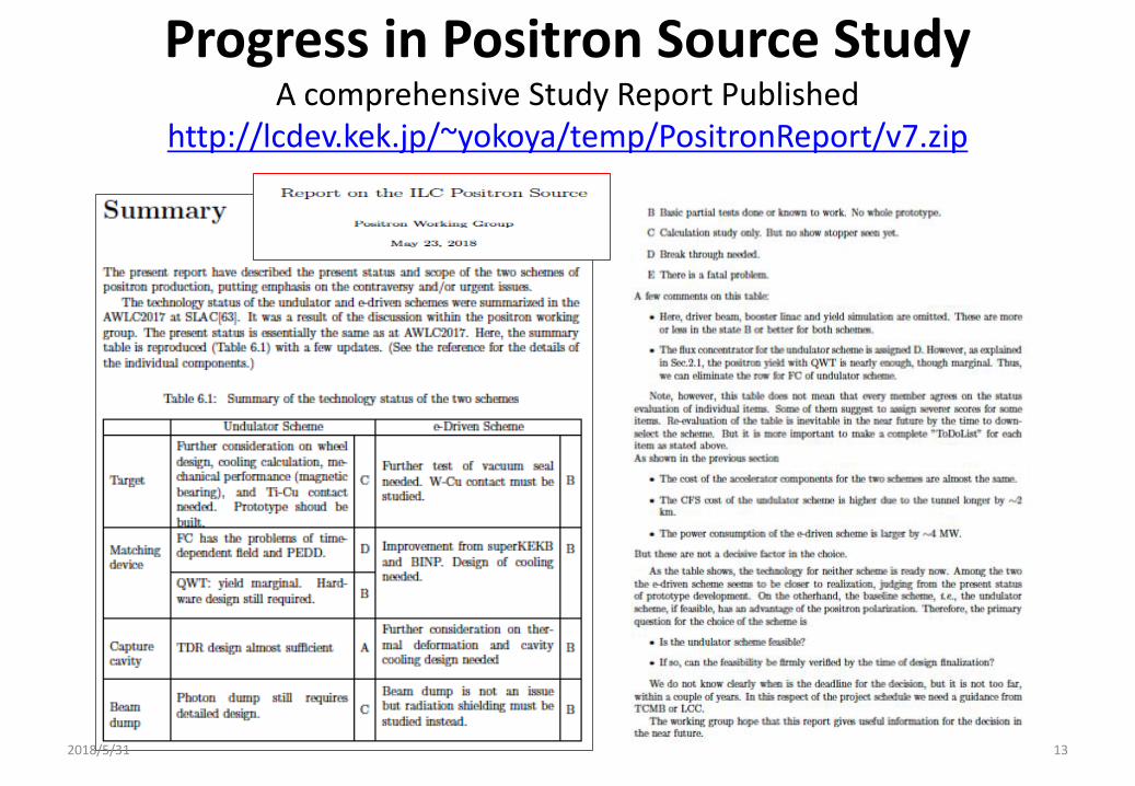
Progress in Positron Source StudyA comprehensive Study Report Published
http://lcdev.kek.jp/~yokoya/temp/PositronReport/v7.zip
2018/5/31 13
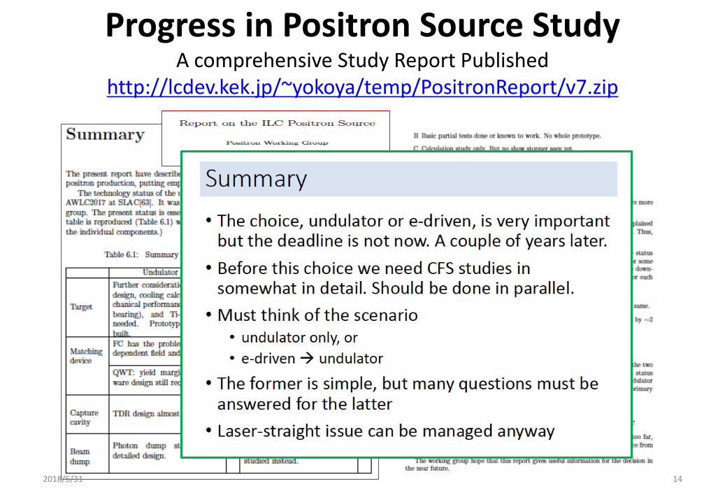
Progress in Positron Source StudyA comprehensive Study Report Published
http://lcdev.kek.jp/~yokoya/temp/PositronReport/v7.zip
2018/5/31 14
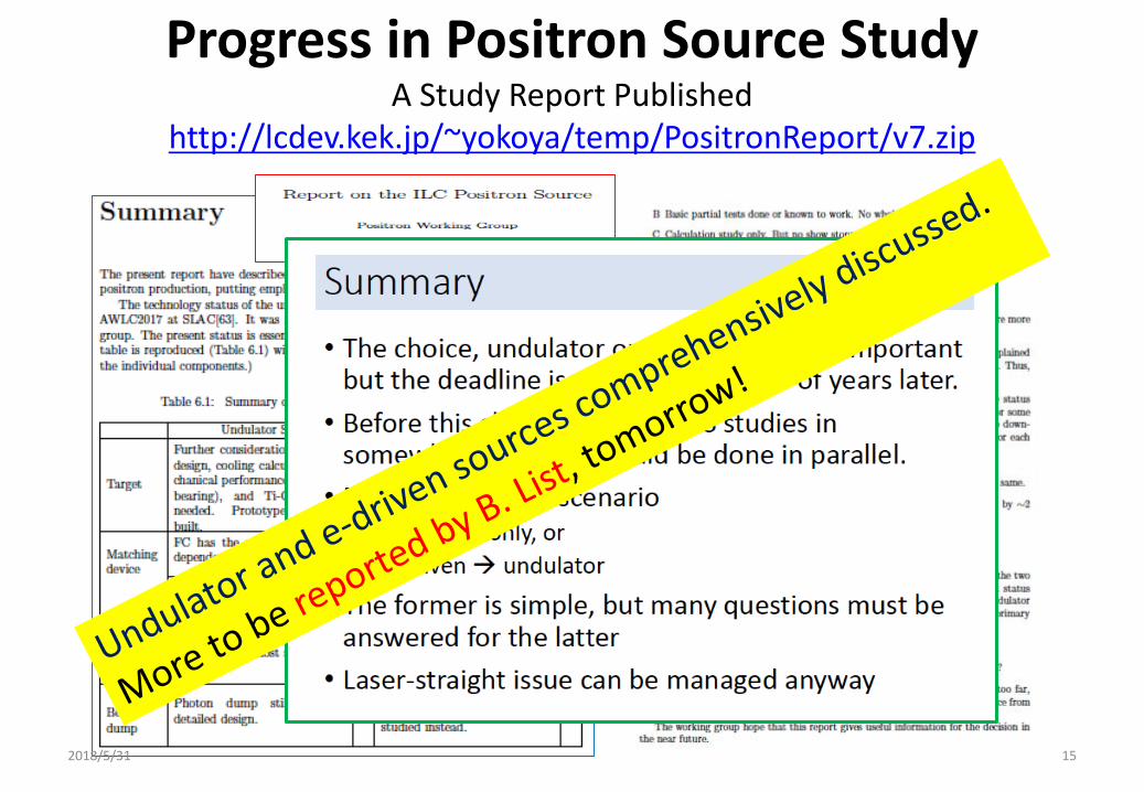
Progress in Positron Source StudyA Study Report Published
http://lcdev.kek.jp/~yokoya/temp/PositronReport/v7.zip
2018/5/31 15
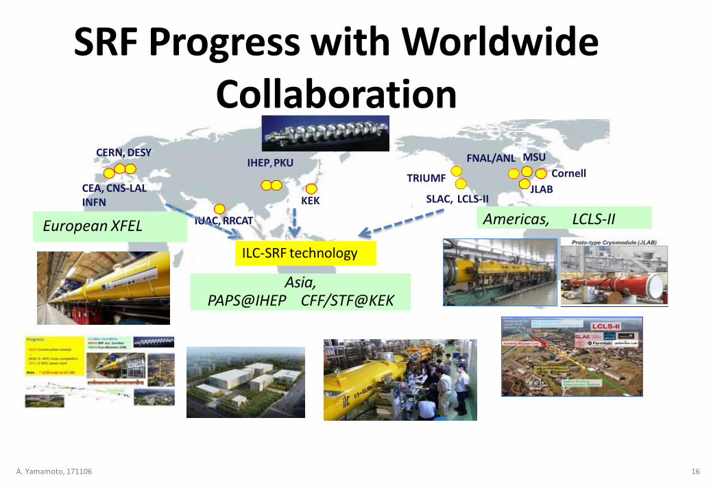
SRF Progress with WorldwideCollaboration
European XFEL
Asia,PAPS@IHEP CFF/STF@KEK
Americas, LCLS-II
FNAL/ANL
Cornell
JLABKEK
CERN, DESY
SLAC, LCLS-IICEA, CNS-LALINFN
IHEP, PKU
IUAC, RRCAT
TRIUMF
ILC-SRF technology
MSU
A. Yamamoto, 171106 16
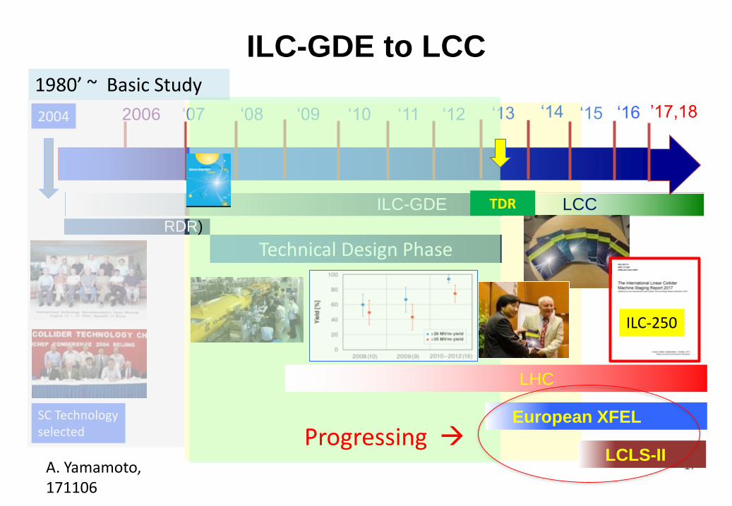
ILC-GDE to LCC
Technical Design Phase
ILC-GDE
2006 ‘07 ‘08 ‘12‘09 ‘10 ‘11 ‘13
SC Technologyselected
RDR)
LCC
LHC
2004
TDR
1980’ ~ Basic Study
‘14 ‘15 ‘16 ’17,18
A. Yamamoto, 171106
17
European XFEL
LCLS-II
TDR
Progressing
ILC-250
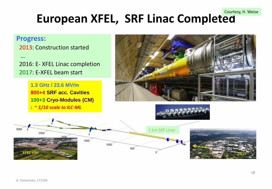
European XFEL, SRF Linac Completed
Progress:2013: Construction started
…
2016: E- XFEL Linac completion
2017: E-XFEL beam start
XFEL site DESY
1 km SRF Linac
18
A. Yamamoto, 171106
Courtesy, H. Weise
1.3 GHz / 23.6 MV/m
800+4 SRF acc. Cavities
100+3 Cryo-Modules (CM)
: ~ 1/10 scale to ILC-ML
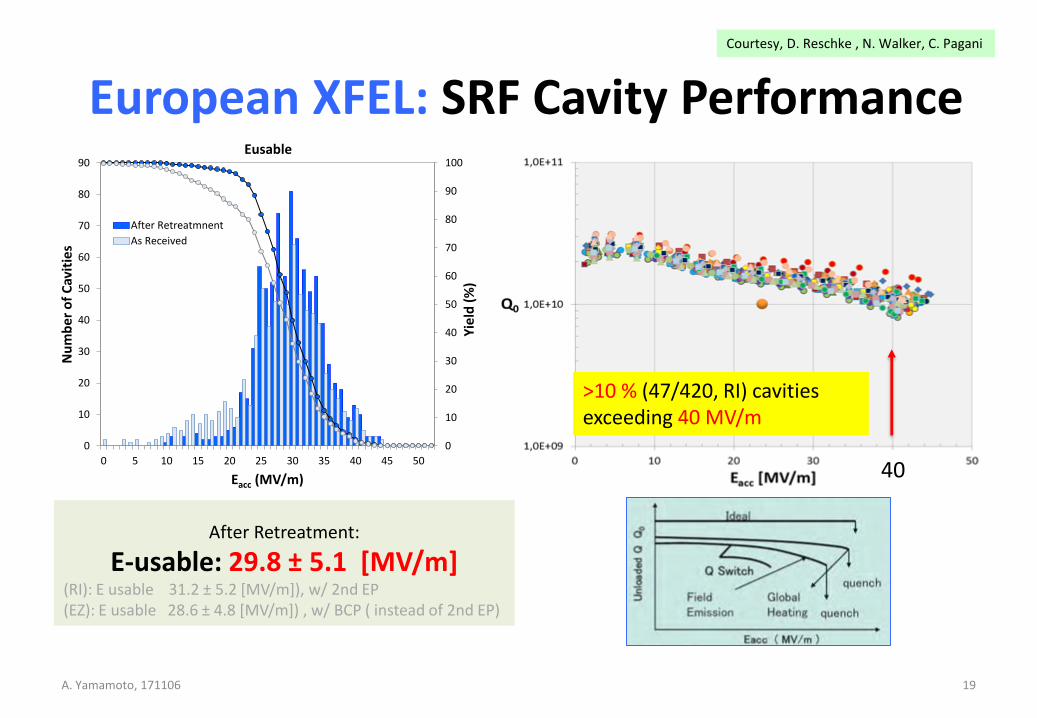
European XFEL: SRF Cavity Performance
19
Courtesy, D. Reschke , N. Walker, C. Pagani
>10 % (47/420, RI) cavities exceeding 40 MV/m
0
10
20
30
40
50
60
70
80
90
100
0
10
20
30
40
50
60
70
80
90
0 5 10 15 20 25 30 35 40 45 50Y
ield
(%
)
Nu
mb
er
of
Cav
itie
s
Eacc (MV/m)
Eusable
After Retreatmnent
As Received
After Retreatment:
E-usable: 29.8 ± 5.1 [MV/m](RI): E usable 31.2 ± 5.2 [MV/m]), w/ 2nd EP(EZ): E usable 28.6 ± 4.8 [MV/m]) , w/ BCP ( instead of 2nd EP)
A. Yamamoto, 171106
40
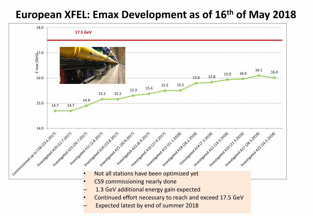
European XFEL: Emax Development as of 16th of May 2018
14.7 14.7
14.9
15.2 15.215.3 15.4
15.5 15.5
15.8 15.815.9 16.0
16.116.0
14.0
15.0
16.0
17.0
18.0
E m
ax [
GeV
]17.5 GeV
• Not all stations have been optimized yet• CS9 commissioning nearly done
– 1.3 GeV additional energy gain expected
• Continued effort necessary to reach and exceed 17.5 GeV– Expected latest by end of summer 2018
21
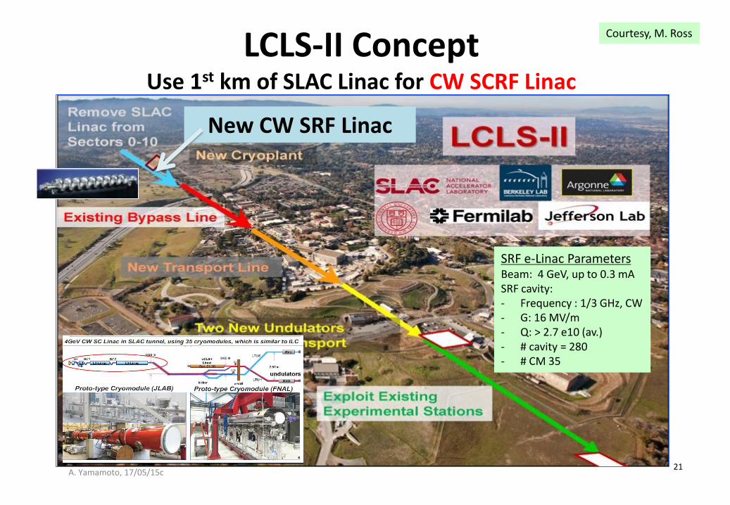
LCLS-II ConceptUse 1st km of SLAC Linac for CW SCRF Linac
New CW SRF Linac
Courtesy, M. Ross
A. Yamamoto, 17/05/15c
SRF e-Linac ParametersBeam: 4 GeV, up to 0.3 mASRF cavity: - Frequency : 1/3 GHz, CW- G: 16 MV/m- Q: > 2.7 e10 (av.)- # cavity = 280 - # CM 35
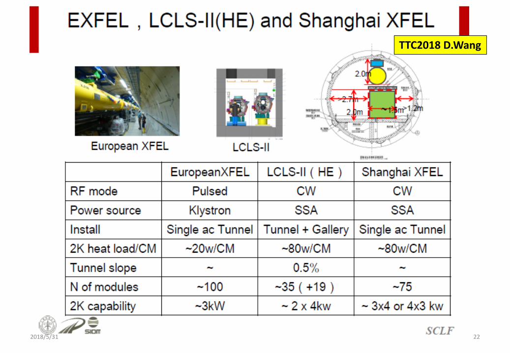
22
TTC2018 D.Wang
2018/5/31
Outline
2018/5/31 23
Introduction
ILC-250 overview
Nano-beam and SRF technologies advanced
Progress in cost-reduction R&D
Summary
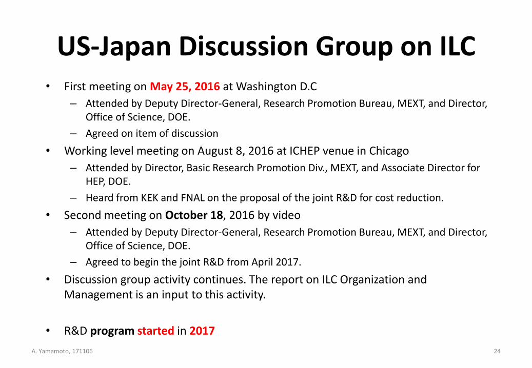
US-Japan Discussion Group on ILC• First meeting on May 25, 2016 at Washington D.C
– Attended by Deputy Director-General, Research Promotion Bureau, MEXT, and Director, Office of Science, DOE.
– Agreed on item of discussion
• Working level meeting on August 8, 2016 at ICHEP venue in Chicago
– Attended by Director, Basic Research Promotion Div., MEXT, and Associate Director for HEP, DOE.
– Heard from KEK and FNAL on the proposal of the joint R&D for cost reduction.
• Second meeting on October 18, 2016 by video
– Attended by Deputy Director-General, Research Promotion Bureau, MEXT, and Director, Office of Science, DOE.
– Agreed to begin the joint R&D from April 2017.
• Discussion group activity continues. The report on ILC Organization and Management is an input to this activity.
• R&D program started in 2017
24A. Yamamoto, 171106
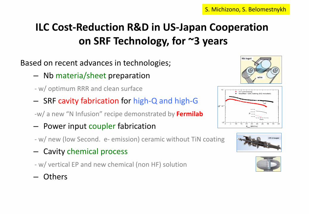
ILC Cost-Reduction R&D in US-Japan Cooperationon SRF Technology, for ~3 years
Based on recent advances in technologies;
– Nb materia/sheet preparation
- w/ optimum RRR and clean surface
– SRF cavity fabrication for high-Q and high-G
-w/ a new “N Infusion” recipe demonstrated by Fermilab
– Power input coupler fabrication
- w/ new (low Second. e- emission) ceramic without TiN coating
– Cavity chemical process
- w/ vertical EP and new chemical (non HF) solution
– Others
New potential breakthrough: very high Q at very high
gradients with low temperature (120C) nitrogen treatment
4/12/16Alexander Romanenko | FCC Week 2016 - Rome34
- Record Q at fields > 30 MV/m
- Preliminary data indicates potential 15% boost in achievable quench fields
- Can be game changer for ILC!
S. Michizono, S. Belomestnykh
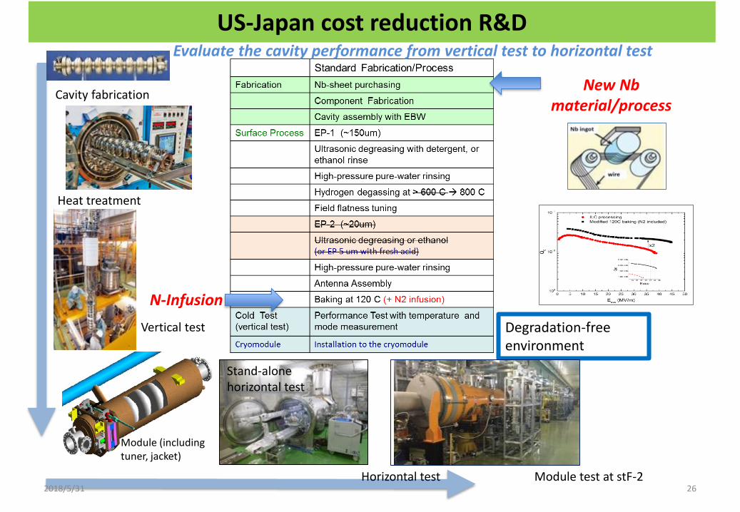
US-Japan cost reduction R&D
New Nbmaterial/process
N-Infusion
Degradation-free environment
Heat treatment
Cavity fabrication
Module (including tuner, jacket)
Vertical test
26Horizontal test
Stand-alone horizontal test
Module test at stF-2
Evaluate the cavity performance from vertical test to horizontal test
2018/5/31
New potential breakthrough: very high Q at very high
gradients with low temperature (120C) nitrogen treatment
4/12/16Alexander Romanenko | FCC Week 2016 - Rome34
- Record Q at fields > 30 MV/m
- Preliminary data indicates potential 15% boost in achievable quench fields
- Can be game changer for ILC!
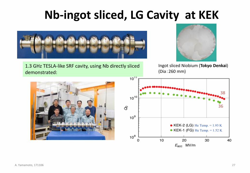
Nb-ingot sliced, LG Cavity at KEK
36
38
1.3 GHz TESLA-like SRF cavity, using Nb directly sliceddemonstrated:
Ingot sliced Niobium (Tokyo Denkai)(Dia:260 mm)
27A. Yamamoto, 171106
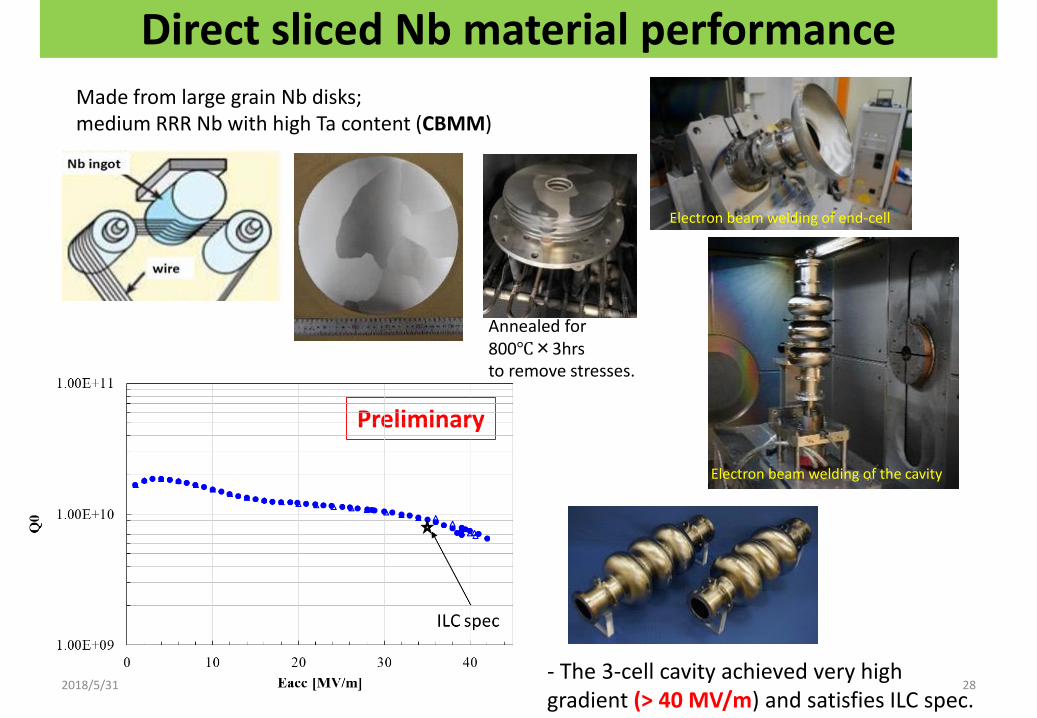
Direct sliced Nb material performance
28
Preliminary
Made from large grain Nb disks; medium RRR Nb with high Ta content (CBMM)
- The 3-cell cavity achieved very high gradient (> 40 MV/m) and satisfies ILC spec.
Annealed for 800℃×3hrsto remove stresses.
Electron beam welding of end-cell
Electron beam welding of the cavity
2018/5/31
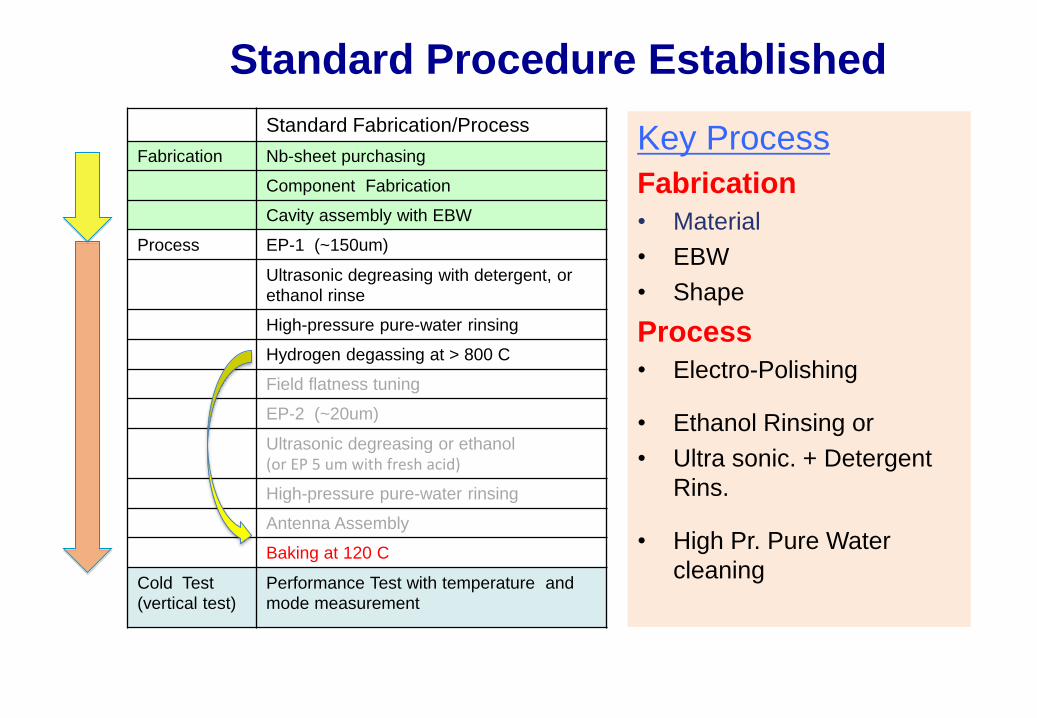
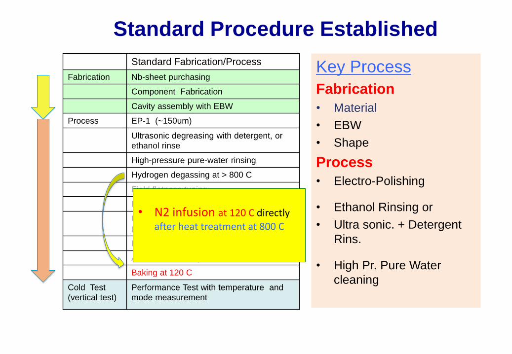
Standard Procedure Established
Standard Fabrication/Process
Fabrication Nb-sheet purchasing
Component Fabrication
Cavity assembly with EBW
Process EP-1 (~150um)
Ultrasonic degreasing with detergent, or
ethanol rinse
High-pressure pure-water rinsing
Hydrogen degassing at > 800 C
Field flatness tuning
EP-2 (~20um)
Ultrasonic degreasing or ethanol (or EP 5 um with fresh acid)
High-pressure pure-water rinsing
Antenna Assembly
Baking at 120 C
Cold Test
(vertical test)
Performance Test with temperature and
mode measurement
Key Process
Fabrication
• Material
• EBW
• Shape
Process
• Electro-Polishing
• Ethanol Rinsing or
• Ultra sonic. + Detergent
Rins.
• High Pr. Pure Water
cleaning
• N2 infusion at 120 C directly
after heat treatment at 800 C
New potential breakthrough: very high Q at very high
gradients with low temperature (120C) nitrogen treatment
4/12/16Alexander Romanenko | FCC Week 2016 - Rome34
- Record Q at fields > 30 MV/m
- Preliminary data indicates potential 15% boost in achievable quench fields
- Can be game changer for ILC!
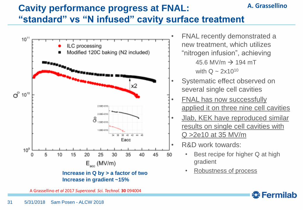
• FNAL recently demonstrated a
new treatment, which utilizes
“nitrogen infusion”, achieving
45.6 MV/m 194 mT
with Q ~ 2x10¹⁰
• Systematic effect observed on
several single cell cavities
• FNAL has now successfully
applied it on three nine cell cavities
• Jlab, KEK have reproduced similar
results on single cell cavities with
Q >2e10 at 35 MV/m
• R&D work towards:
• Best recipe for higher Q at high
gradient
• Robustness of process
Cavity performance progress at FNAL:
“standard” vs “N infused” cavity surface treatment
Sam Posen - ALCW 2018
Increase in Q by > a factor of two
Increase in gradient ~15%
A Grassellino et al 2017 Supercond. Sci. Technol. 30 094004
5/31/201831
A. Grassellino
New potential breakthrough: very high Q at very high
gradients with low temperature (120C) nitrogen treatment
4/12/16Alexander Romanenko | FCC Week 2016 - Rome34
- Record Q at fields > 30 MV/m
- Preliminary data indicates potential 15% boost in achievable quench fields
- Can be game changer for ILC!
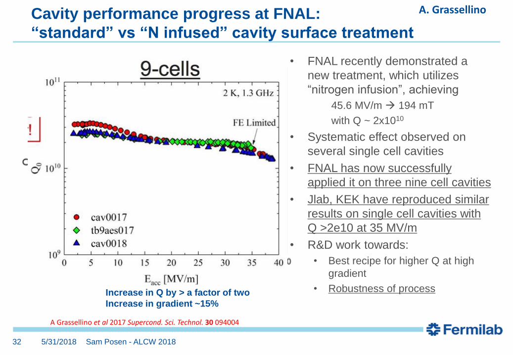
• FNAL recently demonstrated a
new treatment, which utilizes
“nitrogen infusion”, achieving
45.6 MV/m 194 mT
with Q ~ 2x10¹⁰
• Systematic effect observed on
several single cell cavities
• FNAL has now successfully
applied it on three nine cell cavities
• Jlab, KEK have reproduced similar
results on single cell cavities with
Q >2e10 at 35 MV/m
• R&D work towards:
• Best recipe for higher Q at high
gradient
• Robustness of process
Cavity performance progress at FNAL:
“standard” vs “N infused” cavity surface treatment
Sam Posen - ALCW 2018
Increase in Q by > a factor of two
Increase in gradient ~15%
A Grassellino et al 2017 Supercond. Sci. Technol. 30 094004
5/31/201832
A. Grassellino
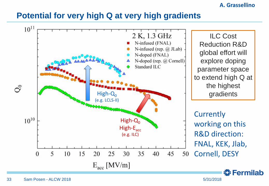
Potential for very high Q at very high gradients
Sam Posen - ALCW 2018
ILC Cost
Reduction R&D
global effort will
explore doping
parameter space
to extend high Q at
the highest
gradientsHigh-Q0(e.g. LCLS-II)
High-Q0
High-Eacc(e.g. ILC)
Currently working on this R&D direction: FNAL, KEK, Jlab, Cornell, DESY
5/31/201833
A. Grassellino
34
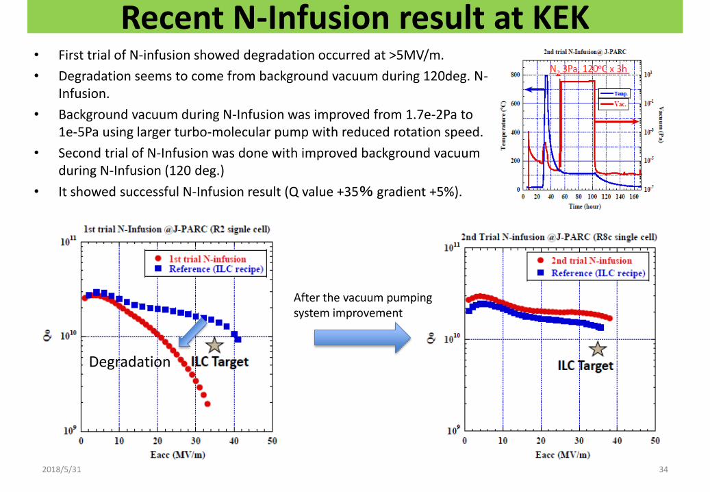
Recent N-Infusion result at KEK• First trial of N-infusion showed degradation occurred at >5MV/m.
• Degradation seems to come from background vacuum during 120deg. N-Infusion.
• Background vacuum during N-Infusion was improved from 1.7e-2Pa to 1e-5Pa using larger turbo-molecular pump with reduced rotation speed.
• Second trial of N-Infusion was done with improved background vacuum during N-Infusion (120 deg.)
• It showed successful N-Infusion result (Q value +35% gradient +5%).
Degradation
After the vacuum pumping system improvement
2018/5/31
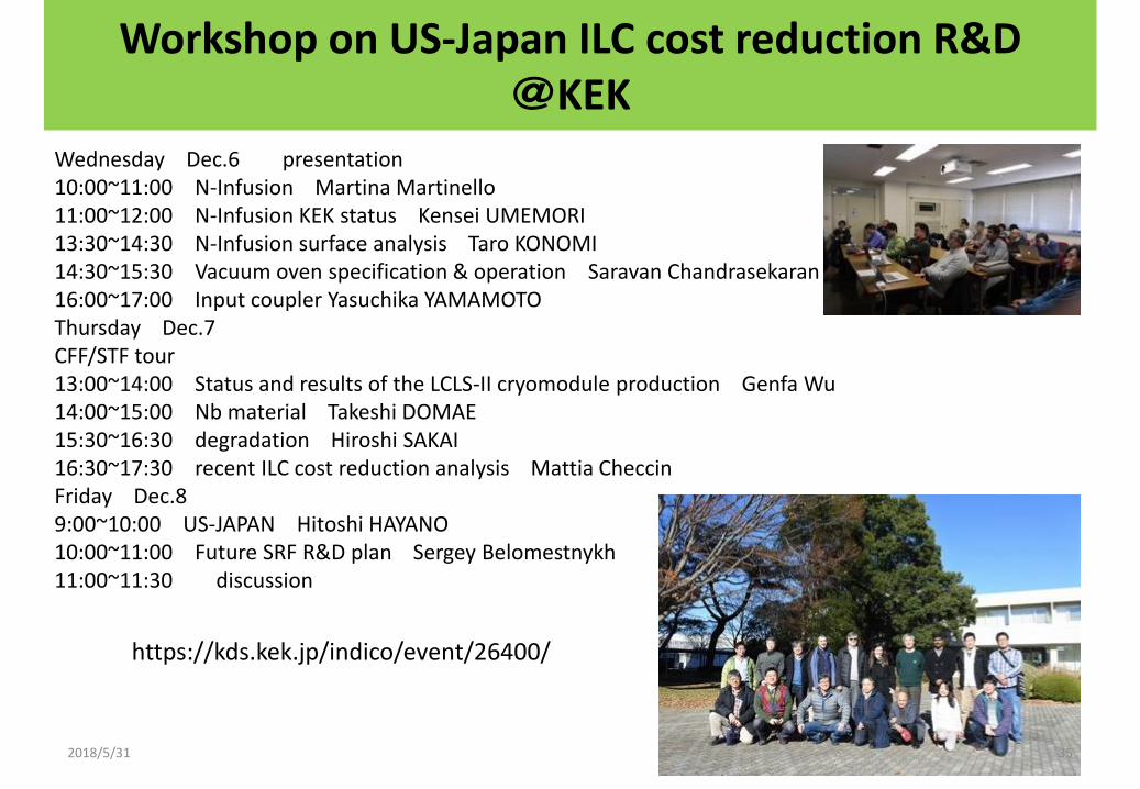
Workshop on US-Japan ILC cost reduction R&D@KEK
Wednesday Dec.6 presentation 10:00~11:00 N-Infusion Martina Martinello11:00~12:00 N-Infusion KEK status Kensei UMEMORI 13:30~14:30 N-Infusion surface analysis Taro KONOMI 14:30~15:30 Vacuum oven specification & operation Saravan Chandrasekaran 16:00~17:00 Input coupler Yasuchika YAMAMOTO Thursday Dec.7 CFF/STF tour13:00~14:00 Status and results of the LCLS-II cryomodule production Genfa Wu 14:00~15:00 Nb material Takeshi DOMAE 15:30~16:30 degradation Hiroshi SAKAI 16:30~17:30 recent ILC cost reduction analysis Mattia CheccinFriday Dec.8 9:00~10:00 US-JAPAN Hitoshi HAYANO 10:00~11:00 Future SRF R&D plan Sergey Belomestnykh11:00~11:30 discussion
https://kds.kek.jp/indico/event/26400/
352018/5/31
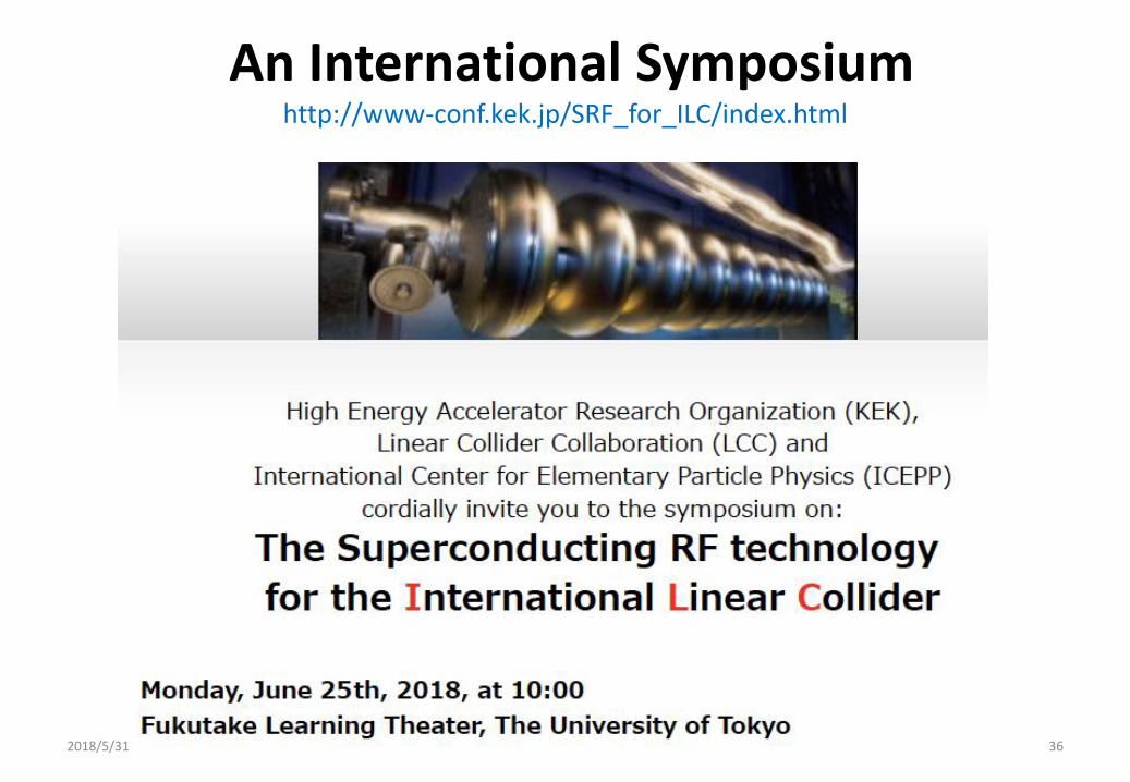
An International Symposium http://www-conf.kek.jp/SRF_for_ILC/index.html
2018/5/31 36
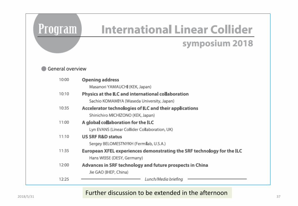
2018/5/31 37Further discussion to be extended in the afternoon
Outline
2018/5/31 38
Introduction
ILC-250 overview
Nano-beam and SRF technologies advanced
Progress in cost-reduction R&D
Summary
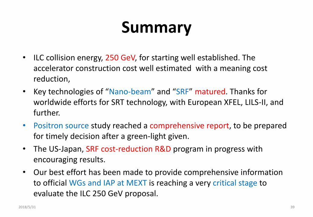
Summary
• ILC collision energy, 250 GeV, for starting well established. The accelerator construction cost well estimated with a meaning cost reduction,
• Key technologies of “Nano-beam” and “SRF” matured. Thanks for worldwide efforts for SRT technology, with European XFEL, LILS-II, and further.
• Positron source study reached a comprehensive report, to be prepared for timely decision after a green-light given.
• The US-Japan, SRF cost-reduction R&D program in progress with encouraging results.
• Our best effort has been made to provide comprehensive information to official WGs and IAP at MEXT is reaching a very critical stage to evaluate the ILC 250 GeV proposal.
2018/5/31 39
backup
2018/5/31 40
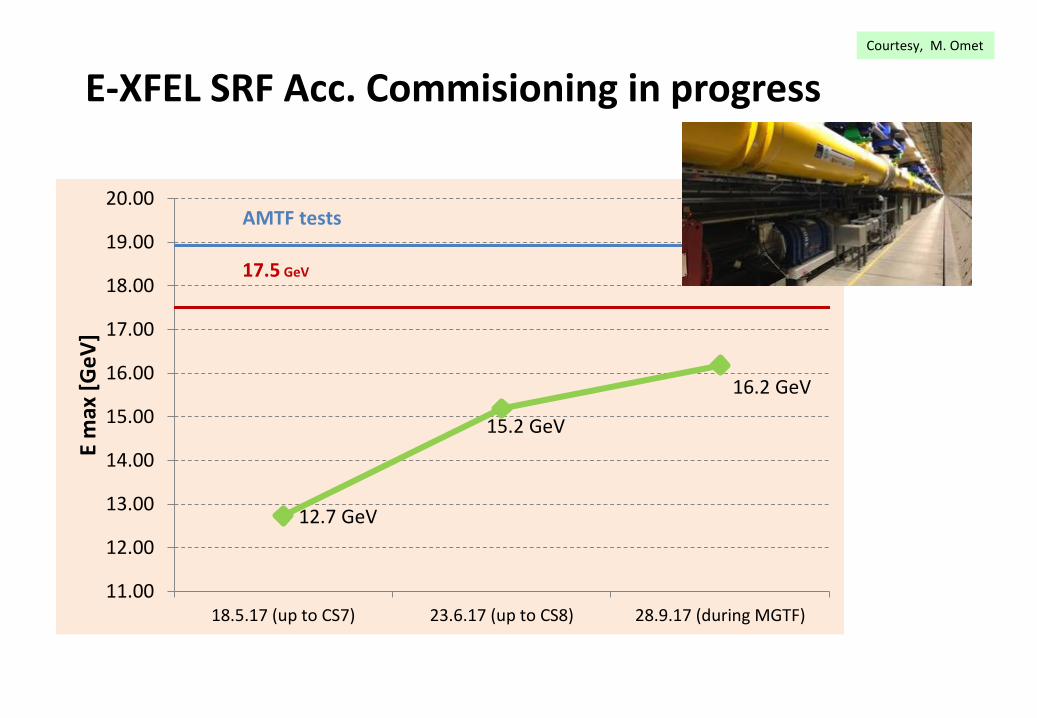
E-XFEL SRF Acc. Commisioning in progress
12.7 GeV
15.2 GeV
16.2 GeV
11.00
12.00
13.00
14.00
15.00
16.00
17.00
18.00
19.00
20.00
18.5.17 (up to CS7) 23.6.17 (up to CS8) 28.9.17 (during MGTF)
E m
ax [
Ge
V]
AMTF tests
17.5 GeV
Courtesy, M. Omet
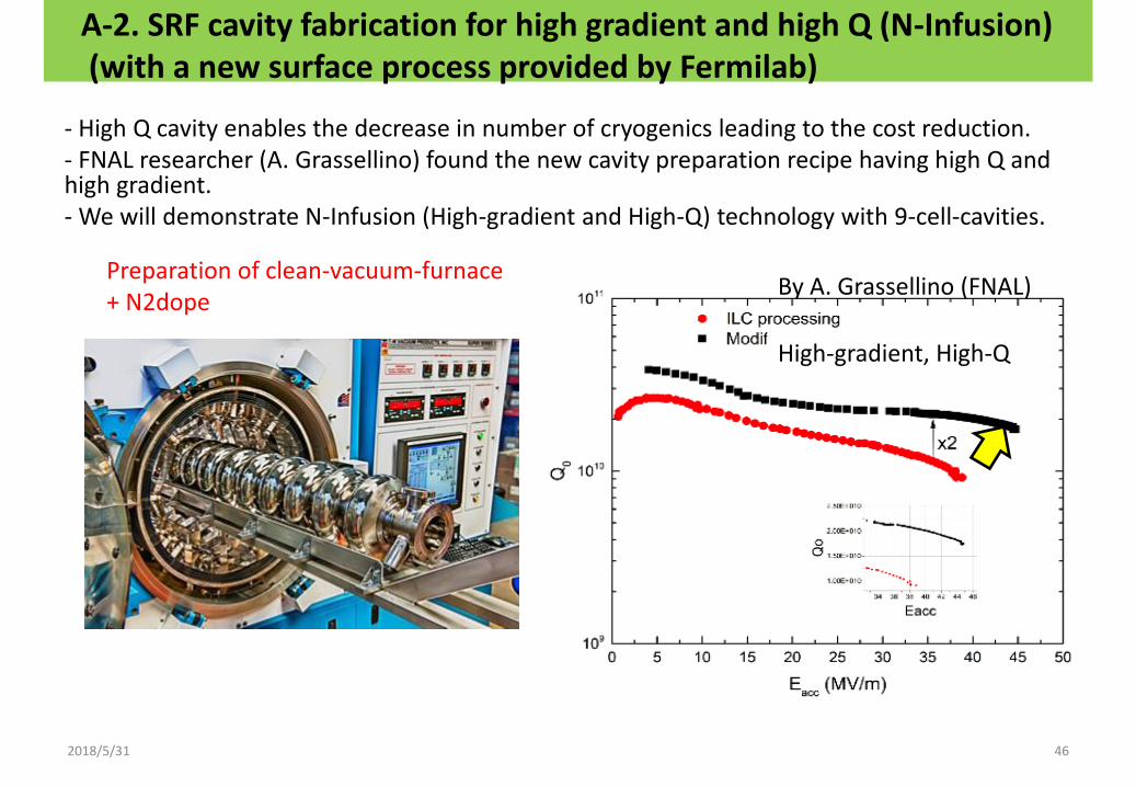
A-2. SRF cavity fabrication for high gradient and high Q (N-Infusion)(with a new surface process provided by Fermilab)
High-gradient, High-Q
example of Cornell
46
- High Q cavity enables the decrease in number of cryogenics leading to the cost reduction. - FNAL researcher (A. Grassellino) found the new cavity preparation recipe having high Q and high gradient. - We will demonstrate N-Infusion (High-gradient and High-Q) technology with 9-cell-cavities.
By A. Grassellino (FNAL)Preparation of clean-vacuum-furnace + N2dope
2018/5/31