VME - CAN4 - ESD Electronics Inc
40
VME-CAN4 Hardware Manual Rev. 1.5 esd electronic system design gmbh Vahrenwalder Str. 207 • 30165 Hannover • Germany www.esd-electronics.com • Fax: 0511/37 29 8-68 Phone: 0511/37 29 80 • International: +49-5 11-37 29 80 VME - CAN4 CAN Controller for 4 CAN Nets Hardware Manual to Product V.1408.xx
Transcript of VME - CAN4 - ESD Electronics Inc

VME-CAN4 Hardware Manual Rev. 1.5esd electronic system design gmbh
Vahrenwalder Str. 207 • 30165 Hannover • Germany www.esd-electronics.com • Fax: 0511/37 29 8-68
Phone: 0511/37 29 80 • International: +49-5 11-37 29 80
VME - CAN4
CAN Controller for 4 CAN Nets
Hardware Manual
to Product V.1408.xx

VME-CAN4 Hardware Manual Rev. 1.5
N O T E
The information in this document has been carefully checked and is believed to be entirely reliable. esdmakes no warranty of any kind with regard to the material in this document, and assumes noresponsibility for any errors that may appear in this document. esd reserves the right to make changeswithout notice to this, or any of its products, to improve reliability, performance or design.
esd assumes no responsibility for the use of any circuitry other than circuitry which is part of a productof esd gmbh.
esd does not convey to the purchaser of the product described herein any license under the patent rightsof esd gmbh nor the rights of others.
esd electronic system design gmbhVahrenwalder Str. 20730165 HannoverGermany
Phone: +49-511-372 98-0Fax: +49-511-372 98-68E-mail: [email protected]: www.esd-electronics.com
USA / Canada:esd electronics Inc.525 Bernardston RoadSuite 1Greenfield, MA 01301 USA
Phone: +1-800-732-8006Fax: +1-800-732-8093E-mail: [email protected]: www.esd-electronics.us

VME-CAN4 Hardware Manual Rev. 1.5
Manual File: I:\texte\Doku\MANUALS\VME\CAN4\CAN4-15H.en9
Date of Print: 27.06.2006
Described PCB Version: from serial no.$ BAxxxx
Changes in the chapters
The changes in the user's manual listed below affect changes in the hardware, as well as changes in thedescription of the facts only.
Chapter Alternations versus previous revision 1.0
- General revision.
4.7 New chapter ‘4.7 Wake-Up Timer’ inserted.
6. Chapter ‘6. User Clock’ deleted. Function is no longer available.
6.1.2 P2 pin assignment description changed.
7.3 Circuit diagrams deleted. (If required, please ask our support team for the‘Engineering Manual’.)
Technical details are subject to change without notice.

VME-CAN4 Hardware Manual Rev. 1.5
This page is intentionally left blank.

Content Page
VME-CAN4 Hardware Manual Rev. 1.5 1
1. Overview . . . . . . . . . . . . . . . . . . . . . . . . . . . . . . . . . . . . . . . . . . . . . . . . . . . . . . . . . . . . . . . . . 31.1 Summary of the Technical Data . . . . . . . . . . . . . . . . . . . . . . . . . . . . . . . . . . . . . . . . . . . . . . 5
1.1.1 General . . . . . . . . . . . . . . . . . . . . . . . . . . . . . . . . . . . . . . . . . . . . . . . . . . . . . . . . . . . . 51.1.2 VMEbus Interface . . . . . . . . . . . . . . . . . . . . . . . . . . . . . . . . . . . . . . . . . . . . . . . . . . . . 51.1.3 Four CAN Units . . . . . . . . . . . . . . . . . . . . . . . . . . . . . . . . . . . . . . . . . . . . . . . . . . . . . 6
1.1.3.1 Microprocessor Assemblies . . . . . . . . . . . . . . . . . . . . . . . . . . . . . . . . . . . . . . . 61.1.3.2 CAN-Interface Assembly . . . . . . . . . . . . . . . . . . . . . . . . . . . . . . . . . . . . . . . . . 7
1.1.4 Software . . . . . . . . . . . . . . . . . . . . . . . . . . . . . . . . . . . . . . . . . . . . . . . . . . . . . . . . . . . 71.2 Order Information . . . . . . . . . . . . . . . . . . . . . . . . . . . . . . . . . . . . . . . . . . . . . . . . . . . . . . . . 8
2. PCB View . . . . . . . . . . . . . . . . . . . . . . . . . . . . . . . . . . . . . . . . . . . . . . . . . . . . . . . . . . . . . . . . . 9
3. Address Assignment . . . . . . . . . . . . . . . . . . . . . . . . . . . . . . . . . . . . . . . . . . . . . . . . . . . . . . . 113.1 Address Modifier . . . . . . . . . . . . . . . . . . . . . . . . . . . . . . . . . . . . . . . . . . . . . . . . . . . . . . . . 113.2 Accesses to the VME-CAN4 in A16 Mode . . . . . . . . . . . . . . . . . . . . . . . . . . . . . . . . . . . . 12
3.2.1 A16-Basic Address . . . . . . . . . . . . . . . . . . . . . . . . . . . . . . . . . . . . . . . . . . . . . . . . . . 123.2.2 A16 Address Area Assignment . . . . . . . . . . . . . . . . . . . . . . . . . . . . . . . . . . . . . . . . . 13
3.3 Accesses to the VME-CAN4 in A24 or A32 Mode . . . . . . . . . . . . . . . . . . . . . . . . . . . . . . 14
4. Registers of the VME-CAN4 . . . . . . . . . . . . . . . . . . . . . . . . . . . . . . . . . . . . . . . . . . . . . . . . . 154.1 Register 'CAR' . . . . . . . . . . . . . . . . . . . . . . . . . . . . . . . . . . . . . . . . . . . . . . . . . . . . . . . . . . 154.2 Status Register 'CSTAT' . . . . . . . . . . . . . . . . . . . . . . . . . . . . . . . . . . . . . . . . . . . . . . . . . . 164.3 IRQ-Counters HIGH and LOW . . . . . . . . . . . . . . . . . . . . . . . . . . . . . . . . . . . . . . . . . . . . . 174.4 Interrupt-Vector Register . . . . . . . . . . . . . . . . . . . . . . . . . . . . . . . . . . . . . . . . . . . . . . . . . . 18
4.4.1 Determine Interrupt Level and Vector (IRLEV) . . . . . . . . . . . . . . . . . . . . . . . . . . . . . 184.4.2 Reading Interrupt-Vector Register . . . . . . . . . . . . . . . . . . . . . . . . . . . . . . . . . . . . . . . 19
4.4.2.1 Reading the Interrupt-Vector Register with Acknowledging the InterruptSource . . . . . . . . . . . . . . . . . . . . . . . . . . . . . . . . . . . . . . . . . . . . . . . . . . . . . . 20
4.4.2.2 Reading the Interrupt-Vector Register with General Status Message . . . . . . . . 214.4.2.3 Reading the Interrupt-Vector Register without Status Message . . . . . . . . . . . . 22
4.5 FIFO Latch . . . . . . . . . . . . . . . . . . . . . . . . . . . . . . . . . . . . . . . . . . . . . . . . . . . . . . . . . . . . 234.7 Wake-Up Timer . . . . . . . . . . . . . . . . . . . . . . . . . . . . . . . . . . . . . . . . . . . . . . . . . . . . . . . . . 24
5. LED Description . . . . . . . . . . . . . . . . . . . . . . . . . . . . . . . . . . . . . . . . . . . . . . . . . . . . . . . . . . 255.1 Position of the LEDS in the Front Panel . . . . . . . . . . . . . . . . . . . . . . . . . . . . . . . . . . . . . . . 255.2 Function of the LEDs . . . . . . . . . . . . . . . . . . . . . . . . . . . . . . . . . . . . . . . . . . . . . . . . . . . . . 26
6. Appendix . . . . . . . . . . . . . . . . . . . . . . . . . . . . . . . . . . . . . . . . . . . . . . . . . . . . . . . . . . . . . . . . 276.1 Connector Assignments . . . . . . . . . . . . . . . . . . . . . . . . . . . . . . . . . . . . . . . . . . . . . . . . . . . 27
6.1.1 VMEbus P1 . . . . . . . . . . . . . . . . . . . . . . . . . . . . . . . . . . . . . . . . . . . . . . . . . . . . . . . . 276.1.2 Signals on P2 . . . . . . . . . . . . . . . . . . . . . . . . . . . . . . . . . . . . . . . . . . . . . . . . . . . . . . . 286.1.3 Meaning of the I/O Signals on P2 . . . . . . . . . . . . . . . . . . . . . . . . . . . . . . . . . . . . . . . . 296.1.4 Connector of the CAN Interfaces P680...P980 (9-pin DSUB male) . . . . . . . . . . . . . . 306.1.5 Optional Mini-DSUB Connector in the Front Panel . . . . . . . . . . . . . . . . . . . . . . . . . . 31
6.2 Front Panel . . . . . . . . . . . . . . . . . . . . . . . . . . . . . . . . . . . . . . . . . . . . . . . . . . . . . . . . . . . . 32
7. Correctly Wiring Electrically Insulated CAN Networks . . . . . . . . . . . . . . . . . . . . . . . . . . . 33

VME-CAN4 Hardware Manual Rev. 1.52
This page is intentionally left blank.

Overview
VME-CAN4 Hardware Manual Rev. 1.5 3
P1/
P2
VM
Eb
us
Physical layerISO 11898
DCDC
CANDSUB9
Control logic,arbiter
VMEinterrupt
control logic
VMEdata bus
driver
addr
ess
and
cont
rol s
igna
ls
VME addressdriver and
AM decoderSRAM
256 kByte
CPU68331/20 MHzad
dres
sShared RAM
512 kbyte(2 Mbyte)
FlashEPROM
256 kbyte
data
FIFOto master
FIFOto slave
CANControllerSJA1000(82C200)
MOTOROLADebug port
data
address and control signalsda
ta
data
data
control / datacont
rol s
igna
ls
electrical isolation
4 intelligent CAN interfaceswith
CPU and CAN controller
CAN control unit 2CAN control unit 3
CAN control unit 4
CAN control unit 1
1. Overview
This manual describes the hardware properties of the VME-CAN4 board. The VME-CAN4 offers fourcomplete, independent CAN interfaces for the VMEbus in 6 U high with a width of only 4 HP.
Fig. 1.1.1: Block diagram of the VME-CAN4
Each interface has its own 68331 microcontroller with a clock frequency of 20 MHz. Eachmicrocontroller has a scratchpad memory of 256 kbytes. The program code of the microcontrollers isloaded from the local flash EPROM after a RESET. Program updates can be programmed into the flashEPROM via the VMEbus.
CAN data are transferred to and from the VMEbus via a shared RAM with a capacity of 512 kbytes andFIFOs. Received CAN-Rx data triggers a local interrupt which is handled by the respectivemicrocontroller. It stores the data in the shared RAM and the identifier in the FIFO (FIFO to master)and triggers a VMEbus interrupt. For each of the four CAN channels their own interrupt vector isgenerated.
For the transmission of CAN data the VMEbus master enters the data into the shared RAM. Doing thisa pointer is automatically stored on the identifier in the FIFO (FIFO to slave). The accordingmicrocontroller reads-out FIFO and RAM and initiates the transmission of data.
The CAN controller used - model SJA1000 - supports the standard CAN protocol (11-bit identifier) aswell as the extended CAN protocol (29-bit identifier). The physical layer corresponds to ISO 11898 fora maximum baudrate of up to 1 Mbit/s. The baudrate can be programmed from 10 kbit/s to 1 Mbit/s.
The CAN channels are electrically isolated from each other as well as from the VME side. The localsupply of the four channels is guaranteed by four DC/DC converters. Even with an electrically isolation,esd guarantees a bus length of 37 m at a transmission rate of 1 Mbit/s, provided that the other CANusers have equivalent CAN interfaces.

Overview
VME-CAN4 Hardware Manual Rev. 1.54
The CAN nets are connected by means of 9-pin DSUB female connectors in the front panel. Apiggyback interface is available for other layers or connector standards (e.g. DeviceNet).
The states of the CAN controllers and the microcontrollers of the individual channels as well as thegeneral board status are indicated by LEDs in the front panel.
The remarkable fault-tolerant CAN protocol (Hamming distance = 6) excellently suits the constructionof decentralized I/O nets in which a secure and manufacturer-independent communication protocol isrequired because of the variety of the applications. The CAN protocol has a standardized transmissionframe and a high transmission speed.
An important advantage of the CAN protocol is its ability of self-arbitration and its multimaster ability,so that the user can interconnect various sensors, actuators, CAN-I/O modules, but also VMEbuscomputers, PCs, PLC assemblies or stand-alone controllers in a CAN net.

Overview
VME-CAN4 Hardware Manual Rev. 1.5 5
1.1 Summary of the Technical Data
1.1.1 General
Plug-in dimensions 6 U high / 4 HP wide
PCB dimensions 160 mm x 233 mm
Weight ca. 380 g
Component design SMD (components equipped on both PCB layers)
ConnectorsP1 - DIN 41612-C96 (VMEbus)P2 - DIN 41612-C96 (VMEbus and PGM signals) P680, P780, P880, P980 - DSUB9/male (CAN interfaces)
Voltage supply viaVMEbus +5 V ±5% Current consumption
(idle, typical):
I1_CAN = 1,9 AI2_CAN = 2,1 AI4_CAN = 2,5 A
Temperature range max. permissible ambient temperature: 0...60 /C
Humidity max. 90%, not condensing
1.1.2 VMEbus Interface
VMEbus interface IEEE 1014 Rev. D
Address modifierstandard supervisory and non privileged data access, extended supervisory and non privileged data access, short supervisory and non privileged data access
Access modes A32, A24: D8, D16, D32, ADO, UAT, RMW
Basic address
A16 - basic address selectable via geographical address (like VME64)or coding switches,A24/A32-basic addresses programmable by A16/D16 access, theboard needs 2 Mbytes

Overview
VME-CAN4 Hardware Manual Rev. 1.56
1.1.3 Four CAN Units
Each one of the following assemblies is available once for each CAN channel (therefore four times alltogether), except the shared SRAM, the flash EPROM and the FIFO to master.
1.1.3.1 Microprocessor Assemblies
1x
FIFO tomaster
Memory capacity: 1 kwordsAccess: VMEbus read (IRQ service, word access +2 bits
FIFO parity for the IACK vector),MC68331 write (word access + 2 bits FIFO parityas channel ID code)
Shared RAM(only one)
Memory capacity: 512 kbytes, optional 2 Mbytes, Access: 68331 and VMEbus with 32-bits data width
Flash EPROM Memory capacity: 256 kbytes, optional 1 MbyteAccess: 68331 (word access)
4x
CPU 68331/ 20 MHz(CPU can be set to 'RESET' by means of the VMEbus.)
SRAM Memory capacity: 256 kbytesAccess: only via 68331
FIFO to slaveMemory capacity: 4 kbytesAccess: 68331 read (IRQ service, byte access),
VMEbus write (word access)

Overview
VME-CAN4 Hardware Manual Rev. 1.5 7
1.1.3.2 CAN-Interface Assembly (one each per CAN channel)
CAN controller SJA1000 (CAN2.0A/CAN2.0B)
Identifier 11-bits and 29-bits identifiers with SJA1000
Baudrate max. 1 Mbit/s, with a maximum bus length of 37 m (provided that theother CAN users have an equivalent interface)
Physical layer differential, ISO 11898
Connection 9-pin DSUB connectors (DIN41625) in front panel
Electrical isolation from VMEbus and channels from each other. Isolation is made bymeans of optocouplers and DC/DC converters.
Voltage supply one DC/DC converter each for the voltage supply of a CAN channel
1.1.4 Software
The integrated firmware offers communication on the OSI-layer 2 level or by superordinate CANprotocols.
The software will be described in a separate manual.

Overview
VME-CAN4 Hardware Manual Rev. 1.58
1.2 Order Information
Model Properties Order no.
VME-CAN4 Intelligent CAN-interface board with 4 independent CANchannels, 11- and 29-bits CAN identifiers (SJA1000) V.1408.02
VME-CAN4-2 as V.1408.02, but 2 CAN channels V.1408.04
VME-CAN4-1 as V.1408.02, but 1 CAN channel V.1408.06
VME-CAN4-64 Option: P1 and P2 designed as 160-pin VMEbusconnector (like VME64) V.1408.12
VME-CAN4-VxW VxWorks object licence P.1408.15
VME-CAN4-LynxOS LynxOS object licence P.1408.53
VME-CAN4-LINUX Linux object licence P.1408.58
VME-CAN4-MD English user’s manual 1*) M.1408.21
VME-CAN4-ENGEngineering manual in English 2*) Content: Circuit diagrams, PCB top overlay drawing, datasheets of significant components
M.1408.25
1*) If module and manual are ordered together, the manual is free of charge.2*) This manual is liable for costs, please contact our support.

PCB View
VME-CAN4 Hardware Manual Rev. 1.5 9
2. PCB View
The coding switch SW210, the diode D210 and the resistors RA211, RA212 and RA213 are designedto set the A16-basic address. They are described in chapter ‘Accesses to the VME-CAN4 in A16 Mode’on page 12.
Fig. 2.1.1: Position of the components on the top layer of the PCB

PCB View
VME-CAN4 Hardware Manual Rev. 1.510
Fig. 2.1.2: Position of the components on the bottom layer of the PCB

Address Assignment
VME-CAN4 Hardware Manual Rev. 1.5 11
3. Address Assignment
3.1 Address Modifier
The VME-CAN4 does not evaluate the address-modifier signal AM2. The following address-modifiercombinations are permitted:
Address Modifierpermitted VMEbus access modes
AM5 AM4 AM3 AM2 AM1 AM0
0 0
1 x 0 1
Selectable via configuration:$0D - extended supervisory data access$09 - extended non-privileged data access
1 0Configuration area (always accessible):$2D - short supervisory access$29 - short non-privileged access
1 1Selectable via configuration:$3D - standard supervisory data access$39 - standard non-privileged data access
Table 3.1.1: Selection of VMEbus accesses via address modifier
Short accesses (A16 mode) via the VMEbus are always possible, because the configuration of the boardhas to be done in this access mode (e.g. determination of the A24- or A32-VME basic address).
Depending on the configuration, standard (A24 mode) or extended accesses can alternatively bepermitted, i.e. the two access modes are not permitted at the same time.

Address Assignment
VME-CAN4 Hardware Manual Rev. 1.512
3.2 Accesses to the VME-CAN4 in A16 Mode
The A16 mode is always active. After a RESET the VME-CAN4 can only be operated in A16 mode,in which the board needs 256 bytes.
By means of A16 accesses the basic address of the board is programmed for A24 and A32 accesses. Inaddition fundamental control functions and status enquiries can be executed.
3.2.1 A16-Basic Address
The A16-basic address of the board is determined by the geographical address of the plug-in positionat P1 (see also VME64 Specification, GAx (x=0...4)). If the board is used in standard-VMEbus systems,the signals GAx (x=0...4) can be simulated at the user-definable pins of the connector P2.
If no valid geographical address is recognized (parity error), the settings of a coding switch and a diodeare used for setting the basic address (standard: diode equipped, i.e. A12 = '0').
The more significant addresses A13...A15 are always compared to the values set by three SMD resistors(standard: no resistor equipped, i.e. A15=A14=A13=’1').
VMEbus A16-basic address
A15 A14 A13 A12 A11 A10 A9 A8 A7...A0
null ohm resistors (default: open)
bits of the geographical address(GAx):
These bits select thelocal registers(CAR, etc.).RA213 RA212 RA211
GA4 GA3 GA2 GA1 GA0
diodeD210
HEX-coding-switch bits(Hx) (only if the
geographical address isinvalid):
'0' H3 H2 H1 H0
Table 3.2.1: Geographical address and VMEbus address

Address Assignment
VME-CAN4 Hardware Manual Rev. 1.5 13
Status of the resistors RA211, RA212 andRA213 and the diodes D210
Evaluation of the assignedaddress bit
not equipped ‘1'
equipped ‘0'
Table 3.2.2: Coding the address by means of resistors and diodes
The resulting A16-address area of the VME-CAN4 therefore is between$xxxxE0yy (default settings) and$xxxxFFyy
Here xxxx is the VMEbus-A16 address area of the used master CPU and yy selects the local registers.
3.2.2 A16 Address Area Assignment
Address bits relativeaddress Assembly Access
modeA7 A6 A5 A4 A3 A2 A1
00
00
xx
xx
xx
xx
01
$0000$0002
register CAR (A24- and A32-address)register CSTAT (status messages)
R/WR
00
11
xx
xx
xx
xx
01
$0040$0042
Wake-Up Timer:write IRQ counter H, ack. IRQwrite IRQ counter L, start timer
WW
11
00
xx
xx
ax
bx
01
$0081$0082
CS-IRQ vectorCS-FIFO latch
R/WR
x... address bit is not evaluated.a, b... access by various addresses (see interrupt-vector description below).
Table 3.2.3: Address assignment in the A16-address area
The registers will be explained in detail in the chapter 'Registers of the VME-CAN4'.

Address Assignment
VME-CAN4 Hardware Manual Rev. 1.514
3.3 Accesses to the VME-CAN4 in A24 or A32 Mode
The VME-CAN4 only reacts to the A24 or A32 accesses, if an A24 or A32-basic address had beenentered into the register 'CAR' and the address has been enabled in the register.The register will be explained in detail in the chapter 'Registers of the VME-CAN4'.
The permissible address modifiers have already been described in the chapter of the same name.
Register
VME-CAN4 Hardware Manual Rev. 1.5 15
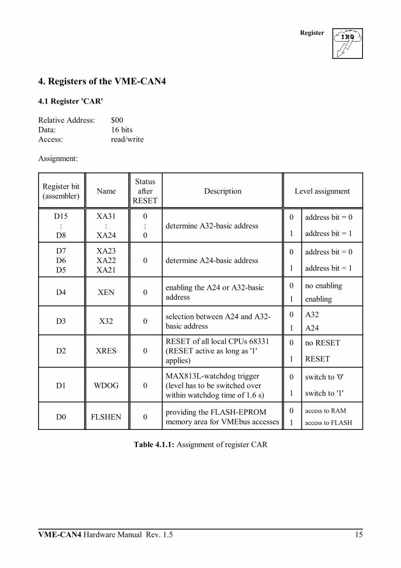
4. Registers of the VME-CAN4
4.1 Register 'CAR'
Relative Address: $00Data: 16 bitsAccess: read/write
Assignment:
Register bit(assembler) Name
Statusafter
RESETDescription Level assignment
D15:
D8
XA31:
XA24
0:0
determine A32-basic address0 address bit = 0
1 address bit = 1
D7D6D5
XA23XA22XA21
0 determine A24-basic address0 address bit = 0
1 address bit = 1
D4 XEN 0 enabling the A24 or A32-basicaddress
0 no enabling
1 enabling
D3 X32 0 selection between A24 and A32-basic address
0 A32
1 A24
D2 XRES 0RESET of all local CPUs 68331(RESET active as long as '1'applies)
0 no RESET
1 RESET
D1 WDOG 0MAX813L-watchdog trigger(level has to be switched overwithin watchdog time of 1.6 s)
0 switch to '0'
1 switch to '1'
D0 FLSHEN 0 providing the FLASH-EPROMmemory area for VMEbus accesses
0 access to RAM
1 access to FLASH
Table 4.1.1: Assignment of register CAR

Register
VME-CAN4 Hardware Manual Rev. 1.516
4.2 Status Register 'CSTAT'
Relative address: $02Data: 16 bitsAccess: read
Assignment:
Register bit(assembler) Name Description Level assignment
D15:
D13
REV2REV1REV0
current software-revision number0 LOW
1 HIGH
D12 GEOADD geographical address is valid (if not, the HEX-coding switch is evaluated)
0 no
1 yes
D11D10D9D8
HVAL3HVAL2HVAL1HVAL0
value set at HEX-coding switch0 LOW
1 HIGH
D7:
D4
CANERR3:
CANERR0error messages of the four CAN channels
0 no error
1 error
D3:
D0
CPUSTAT3:
CPUSTAT0status messages of the four CPU 68331
0 status OK
1 error
Table 4.2.1: Assignment of register CSTAT

Register
VME-CAN4 Hardware Manual Rev. 1.5 17
4.3 IRQ-Counters HIGH and LOW
Relative address: counter HIGH $40counter LOW $42
Data: 16 bits eachAccess: write
Assignment of the register Counter HIGH:
Register bit(assembler) Name Description
D15:
D3- these bits are not evaluated
D2D1D0
Counter D18Counter D17Counter D16
3 MSB of the 19-bits interrupt counterIn addition to setting the counter bits a write access to thisregister acknowledges the interrupt.
Table 4.3.1: Assignment of register Counter HIGH
Assignment of the register Counter LOW
Register bit(assembler) Name Description
D15:
D0
Counter D15:
Counter D0
16 LSB of the 19-bits interrupt counter
In addition to setting the counter a write access to thisregister starts the counting process.
Table 4.3.2: Assignment of register Counter LOW

Register
VME-CAN4 Hardware Manual Rev. 1.518
4.4 Interrupt-Vector Register
4.4.1 Determine Interrupt Level and Vector (IRLEV)
Register name: IRLEVRelative address: $81 (for write access) Data: 8 bitsAccess: write
Register bit(assembler) Name
Statusafter
RESETDescription Level assignment
D7:
D3
VEC7:
VEC3
x:x
programmable and readable 5 most significant bits of theVMEbus-interrupt vector
0 LOW
1 HIGH
D2D1D0
IRLEV2IRLEV1IRLEV0
0 definition of the VMEbus-interrupt level see the following table
Table 4.4.1: Writing the interrupt-vector register IRLEV
IRLEV2 IRLEV1 IRLEV0 VMEbus-interrupt level
0 0 0 no VMEbus IRQ
0001111
0110011
1010101
IRQ 1IRQ 2IRQ 3IRQ 4IRQ 5IRQ 6IRQ 7
Table 4.4.2 Meaning of bits IRLEV0...2

Register
VME-CAN4 Hardware Manual Rev. 1.5 19
4.4.2 Reading Interrupt-Vector Register
There are two possibilities on separate addresses for reading the interrupt-vector register: The 'interrupt-vector register with general status message (ISTAT)' and the 'interrupt-vector register withacknowledging the interrupt source (FSTAT)'.
The registers described below are only needed, if a polling on IRQ level is necessary.
The use of the 5 MSB is the same in both cases. They can be freely programmed by the user.
The registers differ in the 3 LSB and in function. The 'interrupt-vector register with general statusmessage (ISTAT)' only returns in these bits, whether a FIFO interrupt applies or not. It is needed to pollthe FIFO and does not change the FIFO status (no data is read back). It does not say anything about thetriggering CAN channel.
If a read access is made to the 'interrupt-vector register with acknowledging the interrupt source(FSTAT)', and a FIFO IRQ is available, the current FIFO contents is automatically read back and writteninto the FIFO-latch register. In that case the FIFO latch must be read back immediately afterwards sothat the data is not lost (e.g. by a read access of another master to the vector register)! The addressdistributor has been chosen in a way that the interrupt-vector register and the latch can be read by theCAN data by means of a longword read access to $88. This guarantees that no data is lost. The 3 LSBs of the interrupt-vector register contain information about the channel that triggered theinterrupt.

Register
VME-CAN4 Hardware Manual Rev. 1.520
4.4.2.1 Reading the Interrupt-Vector Register with Acknowledging the Interrupt Source
Register name: FSTATRelative address: $89Data: 8 bitsAccess: read/write
Assignment of the interrupt-vector register FSTAT:
Register bit(assembler) Name
Statusafter
RESETDescription Level assignment
D7:
D3
VEC7:
VEC3
x:x
programmable andacknowledgeable 5 mostsignificant data bits of theinterrupt vector
0 LOW
1 HIGH
D2D1D0
FSTATQ2FSTATQ1FSTATQ0
xxx
acknowledgement of theinterrupt source see the following table
Table 4.4.4: Assignment of register FSTAT
FSTATQ2(D2)
FSTATQ1(D1)
FSTATQ0(D0) Vector Interrupt source
00001111
00110011
01010101
01234567
FIFO CAN channel 0FIFO CAN channel 1IRQ counter68331 interrupt (collect IRQ)FIFO CAN channel 2FIFO CAN channel 3not usedno interrupt -> hardware error !
Table 4.4.5: Acknowledgement of the interrupt source
Reading this register initiates the transmission of the FIFO data and the FIFO latch, if the interrupt hasbeen triggered by the FIFO.Furthermore in the interrupt-acknowledge cycle this register corresponds to the returned IRQ vector.

Register
VME-CAN4 Hardware Manual Rev. 1.5 21
4.4.2.2 Reading the Interrupt-Vector Register with General Status Message
Register name: ISTATRelative address: $8DData: 8 bitsAccess: read/write
Assignment of the interrupt-vector register ISTAT:
Register bit(assembler) Name
Statusafter
RESETDescription Level assignment
D7:
D3
VEC7:
VEC3
x:x
programmable and readable mostsignificant 5 data bits of theinterrupt vector
0 LOW
1 HIGH
D2D1D0
FIFO-IRQCNT-IRQ332-IRQ
xxx
acknowledgement of theinterrupt source, each one bit perIRQ source
0 no IRQ
1 IRQ applies
Table 4.4.4: Assignment of register ISTAT
Reading this register has no influence on the FIFO latch.

Register
VME-CAN4 Hardware Manual Rev. 1.522
4.4.2.3 Reading the Interrupt-Vector Register without Status Message
Only to be used for testing!
Register name: IRLEVRelative address: $85Data: 8 bitsAccess: read
Assignment of the interrupt-vector register IRLEV:
Register bit(assembler) Name
Statusafter
RESETDescription Level assignment
D7:
D3
VEC7:
VEC3
x:x
return of the programmed 5 mostsignificant data bits of theinterrupt vector
0 LOW
1 HIGH
D2D1D0
IRLEV2IRLEV1IRLEV0
xxx
return of the programmedinterrupt level see the table on page 18
Table 4.4.4: Assignment of register IRLEV
Reading this registers always transmits the FIFO data into the FIFO latch. It is impossible however, tofind out from which channel the data are. The register should only be read for testing matters!

Register
VME-CAN4 Hardware Manual Rev. 1.5 23
4.5 FIFO Latch
Relative address: $82, $86, $8A, $8E (reflected)Data: 16 bitsAccess: read
Register bit(assembler) Name Status after
RESET Description
D15:
D0
DATA15:
DATA0
x:x
CAN-FIFO data
x... not definedTable 4.5.1: Assignment of register FIFO latch
4.6 Interrupt Priority
If more than one local interrupt occur at the same time, they are handled in the interrupt-acknowledgecycle in the following priority:
Prio IRQ
High: counter IRQMid: 331-IRQLow: FIFO-IRQ

Register
VME-CAN4 Hardware Manual Rev. 1.524
4.7 Wake-Up Timer
The VME-CAN4 can trigger interrupts at the VMEbus to execute independent scheduling by means ofan independent 16-bit counter with a resolution of 1 :s. This Wake-Up timer can only be accessed bythe VMEbus, not by the local CPUs of the VME-CAN4.
The generated VMEbus interrupt is managed by a local interrupt handler and has a specific interruptvector.
The Wake-Up timer is accessed via the A16-address range of the board. The addresses of the timer areprinted at page 13.

LED Description
VME-CAN4 Hardware Manual Rev. 1.5 25
LED2:AgreenStatusCPU 1
LED1:Ared
SYSFAIL
LED1:ByellowBUS
LED1:CredIRQ
LED1:Dgreen,
always off
LED3:Ared
ErrorCAN 1
LED2:BgreenStatusCPU 2
LED3:Bred
ErrorCAN 2
LED2:CgreenStatusCPU 3
LED3:Cred
ErrorCAN 3
LED2:DgreenStatusCPU 4
LED3:Dred
ErrorCAN 4
5. LED Description
5.1 Position of the LEDS in the Front Panel
top
bottom
Fig. 5.1.1: Assignment of LEDs in the front panel

LED Description
VME-CAN4 Hardware Manual Rev. 1.526
5.2 Function of the LEDs
LEDFunction
LED off LED on
LED 1:Ared
SYSFAILSYSFAIL not active.
SYSFAIL active
The signal is active, if at least one CPUis not initialized. The SYSFAIL signal
is guided to the VMEbus.
LED 1:ByellowBUS
No VMEbus access to the VME-CAN4.
Access from VMEbus to the VME-CAN4.
LED 1:CredIRQ
No VMEbus interrupt of the VME-CAN4 is active.
The VMEbus-interrupt signal of theVME-CAN4 is active.
LED 1:DgreenUser
From PCB version $ BAxxxx. on, this LED is no longer in use.The LED is always off.
LED2:A...Dgreen
Status CPU1...4
The respective CPU is notinitialized.
The initialization of the CPU has beensuccessfully completed.
LED 3:A...Dred
Error CAN 1...4
The error flag of the respectiveCAN controller is inactive.
The error flag of the respective CANcontroller is active.

Connector Assignments
VME-CAN4 Hardware Manual Rev. 1.5 27
6. Appendix
6.1 Connector Assignments
6.1.1 VMEbus P1
Pin Row z Row a Row b Row c Row d
123456789
1011121314151617181920212223242526272829303132
-GND-GND-GND-GND-GND-GND-GND-GND-GND-GND-GND-GND-GND-GND-GND-GND
D00D01D02D02D04D05D06D07GND-GNDDS1*DS0*WRITE*GNDDTACK*GNDAS*GNDIACK*IACKIN*IACKOUT*AM4A07A06A05A04A03A02A01-12 V+5 V
---BG0IN* ,BG0OUT* -BG1IN* ,BG1OUT* -BG2IN* ,BG2OUT* -BG3IN* ,BG3OUT* -----AM0AM1-AM3GND--GNDIRQ7*IRQ6*IRQ5*IRQ4*IRQ3*IRQ2*IRQ1*-+5 V
D08D09D10D11D12D13D14D15GNDSYSFAIL*-SYSRESET*LWORD*AM5A23A22A21A20A19A18A17A16A15A14A13A12A11A10A09A08+12 V+5 V
-GND------BGAP*BGA0*BGA1*-BGA2*-BGA3*-BGA4*---------------
male multipoint connector according to DIN41612, Imax per pin : 1.0 A
The connector rows ‘z’ and ‘d’ are only available, if the 160-pin connector design (option ‘VME-CAN4-64') is equipped.]... Signals bridged on board- ... Signal not connected on board

Connector Assignments
VME-CAN4 Hardware Manual Rev. 1.528
6.1.2 Signals on P2
Pin Row z Row a Row b Row c Row d
123456789
1011121314151617181920212223242526272829303132
--------------------------------
----PGA0*PGA2*PGA4*---------------------
----
+5 VGND-A24A25A26A27A28A29A30A31GND+5 VD16D17D18D19D20D21D22D23GNDD24D25D26D27D28D29D30D31GND+5 V
----PGA1*PGA3*PGAP*-------------------------
--------------------------------
male multipoint connector according to DIN41612
The connector rows ‘z’ and ‘d’ are only available, if the 160-pin connector design (option ‘VME-CAN4-64') is equipped.
Imax per pin : 1.0 A
See the following page for signal descriptions.

Connector Assignments
VME-CAN4 Hardware Manual Rev. 1.5 29
6.1.3 Meaning of the I/O Signals on P2
PGA0*... PGA4*, PGAP*... Signals for simulating the geographical address on P2.

Connector Assignments
VME-CAN4 Hardware Manual Rev. 1.530
6.1.4 Connector of the CAN Interfaces P680...P980 (9-pin DSUB male)
Pin Location:
Pin Assignment:
Signal Pin Signal
1 reservedCAN_GND 6
2 CAN_LCAN_H 7
3 CAN_GNDreserved 8
4 reservedreserved 9
5 Shield 9-pole DSUB male
CAN_L, CAN_H... CAN signal lines
CAN_GND ... reference potential of the local CAN-physical layer
Shield... can be connected to the potential of the connector case by means of a solderingbridge
reserved ... reserved for future applications

Connector Assignments
VME-CAN4 Hardware Manual Rev. 1.5 31
6.1.5 Optional Mini-DSUB Connector in the Front Panel
This connector is not equipped in the standard version of the VME-CAN4.
Pin Location:
Pin Assignment:
Signal Pin Signal
+5V 16 CA0
CA1 27 CA2
CA3 38 CA4
CA5 49 CA6
GND 5
CA0...CA6... The function of these signals is not yet defined.

VME-CAN4 Hardware Manual Rev. 1.532
CAN4
CAN4
CAN3
CAN2
CAN1
CP
U
CA
N
1 2 3 4
ST
AT
ADR
Front Panel
6.2 Front Panel

Wiring
VME-CAN4 Hardware Manual Rev. 1.5 33
9
1
4567
9
23
8
1
4567
23
8
CAN_L
CAN_H
CAN_GND
Shielded wire withtransposed wires
CAN_L
CAN_H
CAN_GND(at wire shield)
120
Ohm
120
Ohm
earth (PE)
Wire structure Signal assignment of wire and connection of earthing and terminator
n.c.
n.c.
n.c.
n.c.
n.c.
n.c.
n.c.
n.c.
n.c.
n.c.
n.c.
n.c.
n.c.
n.c.
n.c. = not connected
DSUB9 connector(female or male)pin designation
connector case connector case
DSUB9 connector(female or male)pin designation
CAN wire with connectors
7. Correctly Wiring Electrically Insulated CAN Networks
Generally all instructions applying for wiring regarding an electromagnetic compatible installation,wiring, cross sections of wires, material to be used, minimum distances, lightning protection, etc. haveto be followed.
The following general rules for the CAN wiring must be followed:
1.A CAN net must not branch (exception: short dead-end feeders) and has to be terminatedby the wave impedance of the wire (generally 120 W ±10%) at both ends (between thesignals CAN_L and CAN_H and not at GND)!
2.A CAN data wire requires two twisted wires and a wire to conduct the reference potential(CAN_GND)! For this the shield of the wire should be used!
3. The reference potential CAN_GND has to be connected to the earth potential (PE) at onepoint. Exactly one connection to earth has to be established!
4. The bit rate has to be adapted to the wire length.
5. Dead-end feeders have to kept as short as possible (l < 0.3 m)!
6. When using double shielded wires the external shield has to be connected to the earthpotential (PE) at one point. There must be not more than one connection to earth.
7. A suitable type of wire (wave impedance ca. 120 Ω ±10%) has to be used and the voltageloss in the wire has to be considered!
8. CAN wires should not be laid directly next to disturbing sources. If this cannot be avoided,double shielded wires are preferable.
Figure: Structure and connection of wire

Wiring
VME-CAN4 Hardware Manual Rev. 1.534
l < 0,3 m
CAN_L
CAN_GND
CAN_H
PE
l < 0,3 m
CAN-CBM-AI4
CAN-CBM-COM1
CAN-CBM-DIO8
l < 0,3 ml < 0,3 ml < 0,3 m
Female Connector
Male Connector
e.g.CAN-SPS InterfaceCSC595/2orCAN-PC Board
Terminator
Male Terminator(Order-no.: C.1302.01)
Connecting CAN_GND toProtective Conductor PE
Terminatorwith PE Connector
Female Terminator(Order-no.: C.1301.01)
T-ConnectorC.1311.03
CAN-CableOrder-no.: C.1323.03
Net 2
Net 1 e.g. PCI/405,CAN-USB,
VME-CAN2, etc.
CAN-CableOrder-no.: C.1323.03
CAN-CableOrder-no.: C.1323.03
T-ConnectorC.1311.03
T-ConnectorC.1311.03
T-ConnectorC.1311.03
CAN-Board
T-ConnectorOrder-no.: C.1311.03
Cabling
for devices which have only one CAN connector per net use T-connector and dead-end feeder(shorter than 0.3 m) (available as accessory)
Figure: Example for correct wiring (when using single shielded wires)
Terminal Resistance
use external terminator, because this can later be found again more easily!
9-pin DSUB-terminator with male and female contacts and earth terminal are available asaccessories
Earthing
CAN_GND has to be conducted in the CAN wire, because the individual esd modules areelectrically isolated from each other!
CAN_GND has to be connected to the earth potential (PE) at exactly one point in the net!
each CAN user without electrically isolated interface works as an earthing, therefore: do notconnect more than one user without potential separation!
Earthing CAN e.g. be made at a connector

Wiring
VME-CAN4 Hardware Manual Rev. 1.5 35
Wire Length
Optical couplers are delaying the CAN signals. By using fast optical couplers and testing each boardat 1 Mbit/s, however, esd CAN guarantee a reachable length of 37 m at 1 Mbit/s for most esd CANmodules within a closed net without impedance disturbances like e.g. longer dead-end feeders.(Exception: CAN-CBM-DIO8, -AI4 and AO4 (these modules work only up to 10 m with 1 Mbit/s))
Bit rate[Kbit/s]
Typical values of reachablewire length with esd
interface lmax [m]
CiA recommendations(07/95) for reachable wire
lengths lmin [m]
1000 800
666.6 500
333.3 250 166 125 100
66.6 50
33.3 20
12.5 10
375980
130180270420570710
100014002000360054007300
2550
-100
-250
-500650
-1000
-2500
-5000
Table: Reachable wire lengths depending on the bit rate when using esd-CAN interfaces

Wiring
VME-CAN4 Hardware Manual Rev. 1.536
Examples for CAN Wires
Manufacturer Type of wire
U.I. LAPP GmbHSchulze-Delitzsch-Straße 2570565 StuttgartGermanywww.lappkabel.de
e.g.UNITRONIC ®-BUS CAN UL/CSA (UL/CSA approved)UNITRONIC ®-BUS-FD P CAN UL/CSA (UL/CSA approved)
ConCab GmbHÄußerer Eichwald74535 MainhardtGermanywww.concab.de
e.g.BUS-PVC-C (1 x 2 x 0.22 mm²) Order No.: 93 022 016 (UL appr.)BUS-Schleppflex-PUR-C (1 x 2 x 0.25 mm²) Order No.: 94 025 016 (UL appr.)
SAB Bröckskes GmbH&Co. KGGrefrather Straße 204-212b41749 ViersenGermanywww.sab-brockskes.de
e.g.SABIX® CB 620 (1 x 2 x 0.25 mm²) Order No.: 56202251CB 627 (1 x 2 x 0.25 mm²) Order No.: 06272251 (UL appr.)
Note: Completely configured CAN wires can be ordered from esd.