V OL UM E II - Engineering Projectsengineeringprojects.com/Tender/UploadFiles/3312_Vol-2.pdf ·...
101
ANISO9001&14001COMPANY TENDERDOCUMENT TENDER No: NERO/MMD/STPI-Agartala/253 Dated:05.07.2017 FOR Tender for Renovation and Interior work in IT complex cum Software Technology Park building located at Indranagar, Agartala for creation of state of the art STPI facilities. VOLUME–II NOTICE INVITING TENDER ADDITIONAL CONDITIONS OF CONTRACT TECHNICAL SPECIFICATIONS DRAWINGS
Transcript of V OL UM E II - Engineering Projectsengineeringprojects.com/Tender/UploadFiles/3312_Vol-2.pdf ·...

ANISO9001&14001COMPANY
TENDERDOCUMENT
TENDER No: NERO/MMD/STPI-Agartala/253 Dated:05.07.2017
FOR
Tender for Renovation and Interior work in IT complex cum Software Technology Park building located at Indranagar, Agartala for creation of state of the art STPI facilities.
VOLUME–II
NOTICE INVITING TENDER
ADDITIONAL CONDITIONS OF CONTRACT
TECHNICAL SPECIFICATIONS
DRAWINGS

Tender No: NERO/MMD/STPI-Agartala/253
ENGINEERING PROJECTS (INDIA) LTD. (A Govt. of India Enterprise)
Date:05.07.2017
NOTICE INVITING e-TENDER (NIT)
Tender for Renovation and Interior work in IT complex cum Software Technology Park building located at Indranagar, Agartala for creation of state of the art STPI facilities.
Engineering Projects (India) Ltd., on behalf of Software Technology Parks of India (STPI) invites item rate open e-Tenders through e-tendering from the eligible contractors/firms who fulfill the eligibility criteria as per the brief particulars of scope for Renovation and Interior work in IT complex cum Software Technology Park building located at Indranagar, Agartala for creation of state of the art STPI facilities in single stage Two Envelope system (Technical bid & Price bid) for the following works:
Sl. No. NAME OF WORK ESTIMATED COST EARNEST MONEY DEPOSIT (EMD)
COMPLETION PERIOD
1.
Renovation and Interior work in IT complex cum Software Technology Park building located at Indranagar, Agartala for creation of state of the art STPI facilities
Rs. 3,04,00,000.00
Rs.3,05,000.00 04 Months
The brief scope of work in this tender shall include (but not limited to) providing all labour materials, tools and plant, transportation to site storage and safe custody of the materials, erection, testing, commissioning all complete such as interior and allied works, Sanitary & plumbing, Electrical, Modular work Station, Furniture’s, LAN, CCTV, Video Conferencing, Fire Fighting, Audio Video System works etc. , rectification, maintenance during defect liability period for the project of “Renovation and Interior work in IT complex cum Software Technology Park building located at Indranagar, Agartala for creation of state of the art STPI facilities all complete except those which are specifically mentioned to be excluded elsewhere in tender documents in the buildings mentioned above. Apart from above, any other service not mentioned above but required as per direction of EPI is deemed to be included in the scope of work. The work is to be carried out on item rate basis as per bill of quantities and tender conditions. The detailed scope of work is given in tender document.

Time schedule of Tender activities: (i) Last Date & Time for Downloading of tender documents: up to 14. 07.2017 (12:00 PM)
(ii) Last Date & Time of online submission of Tenders: on or before 14.07.2017 up to 02:00 PM
(iii) Date & Time of online opening of tenders (Techno-Commercial Bid): 14.07.2017 at 04:00 PM
(iv) Pre-bid meeting at 4th Floor, Hindustan Tower Block-A, Jawahar Nagar, N.H.37, Beltola, Guwahati-781022 Assam on 10.07.2017 at 3.00 PM.
(v) Date & Time of submission of documents in physical form: 14.07.2017 (upto 03:00PM) The tenderers shall submit his query for the pre-bid meeting on or before 07.07.2017 by 17.00 hours to [email protected] or by post to the address given at sl.no 14 below.
Contractors who fulfill the following requirements are eligible to participate in this tender. The joint ventures/Consortium are not
accepted.
a) The bidder must have experience of having satisfactorily completed following “similar works” during the last 7(seven)
years ending last day of month previous to the one in which applications are invited.
Three similar works each costing minimum 40% of the estimated cost put to tender OR
Two similar works each costing minimum 50% of the estimated cost put to tender OR
One similar work costing minimum 80% of the estimated cost put to tender
i. The “similar works” shall mean works comprising Civil, Sanitary, Plumbing, Electrical and Internal Finishes etc. in Building work.
ii. The cost of free issue materials shall not be included in the completion cost of works.
iii. For evaluation purpose, the completion cost of works mentioned in the completion certificate shall be enhanced by 7% per

annum till the end of month prior to date of NIT.
iv. The experience certificates issued by Government Organizations/Semi Government Organizations/State Government / Public Works Department / Central Government/Public Sector Undertakings/ Autonomous Bodies/Municipal Bodies/Public Limited Companies listed on BSE/NSE shall only be accepted for assessing the eligibility of the tenderer. However, the certificates issued by Public Limited Company can be considered only if they are supported by TDS certificates in support of value of work done b y the tenderer. TDS certificate for full contract value as mentioned in the work order must match failing which the same shall not be considered.
b) Should have had average annual financial turnover of at least 30% of the estimated cost put to tender during the immediate
last three consecutive financial years ending on 31.03.2016 duly supported by annual financial report (i.e. audited copies of balance sheet and profit and loss statement) or certified by Chartered Accountant along with Income Tax return for last financial year (2015-16/2016-17). Turnover means income from construction works only.
c) Should submit Sale Tax return for last quarter of financial year (2016-17).
d) Should not have incurred any loss in more than two years during the immediate last five consecutive financial
years, ending 31.03.2016, Copies of balance sheet/ Certificate from Chartered Accountant duly self attested by the tenderer shall be submitted.
e) Should have a Solvency of 40% of the estimated cost issued by a Bank. The Solvency Certificate should have been
issued not earlier than one year of last date of submission of the tender.
f) Should have valid Permanent Account Number of Income Tax and GST registration certificate (provisional). In case the tenderer is unable to get migrated to GST Registration he shall give an undertaking to obtain it within one month of issuance of LOI or order in case he becomes the successful bidder.
g) Should have valid PF Registration number. In case the bidder does not have this registration number, he shall remain
bound to obtain them within one month from the date of LOI or before release of 1st R/A bill whichever is earlier. h) Bidders have to submit confirmation letter whether they are registered under MSME Act or not and if yes, then relevant co
pies of the registration letter (Registered under single point registration scheme of NSIC, Govt. of India, Ministry of MSME, New Delhi vide Gazette Notification dated 26.03.2012 along with the form of Memorandum-2 with the concerned DIC) to

be enclosed in Technical Bid and a request letter for exemption from submission of Tender fee and EMD. i) Site visit for the subject tender is mandatory. The bidders shall visit the site to Study/assess the tendered work and also
acquaint themselves of the prevailing local conditions before submitting their bid. Bidder has to enclose a certificate counter signed by EPI official or furnish undertaking for having visited the site.
j) Participation of Joint venture is not allowed.
The credentials of the Bidders shall be verified and inspection of the works, if required, to be carried out by EPI. If not found satisfactory, their bid will be considered non-responsive.
2.0 Tender documents comprising of the following are available on the website of EPI: www.epi.gov.in, CPP-Portal:
www.eprocure.gov.in and as well as on TCIL portal http://www.tcil-india-electronictender.com.
Volume I: Instructions to Tenderers, Addendum to Instructions to Tenderers, Special Instructions to Bidders for e-Tendering & General Conditions of Contract (ITT&GCC) of EPI
Volume II: a) Notice inviting Tender b) Additional Conditions of Contract c) Technical Specification (Electrical) d) Tender Drawings (as mentioned in the list)
Volume III: Price bid/bill of quantity
3.0 In order to participate, the bidder should have Digital Signature Certificate (DSC) from one of the authorized Certifying Authorities.
4.0 Interested bidders have to necessarily register themselves on the portal https://www.tcil-india-electronictender.com through
M/s Telecommunications Consultants India Limited, New Delhi to participate in the bidding under this invitation for bids. It shall be the sole responsibility of the interested bidders to get them registered at the aforesaid portal for which they are required to contact M/s Telecommunications Consultants India Limited, New Delhi at following address to complete the registration formalities:
M/s Telecommunications Consultants India Limited, 6th Floor, TCIL Bhawan, Greater

Kailash – 1, New Delhi 110 048 Contact No.: 011-26241790, 98683 93717/75/92 Email-ID: [email protected]
They may obtain further information regarding this tender from GM (Contracts) at the address given at Clause No.14.0 below from 10:00 hours to 17:00 hours on all working days till the last date of online submission of Bidding Documents.
For proper uploading of the bids on the portal namely https://www.tcil-india-electronictender.com (hereinafter referred to as the “portal‟), it shall be the sole responsibility of the bidders to apprise themselves adequately regarding all the relevant procedures and provisions as detailed at the portal as well as by contacting M/s Telecommunications Consultants India Limited, New Delhi directly, as and when required, for which contact details are mentioned above. The EPI in no case shall be responsible for any issues related to timely or properly uploading/submission of the bid in accordance with the relevant provisions of Section: Instruction to Bidders of the Bidding Documents.
5.0 Bidders can download the bid document from the portal without paying document fees in advance, any time from 20:00 Hrs on 05.07.2017; however interested bidders have to pay tender fees for participating in the tendering and submitting the bid. For this purpose the interested bidders shall be required to pay ` 8,000/-(Rupees Eight Thousand only) as non-refundable document fees in the form of Demand Draft in favour of “Engineering Projects (India) Ltd.” payable at Guwahati.
6.0 E-Bids must be submitted/uploaded along with scanned copies of relevant documents as mentioned at clause no 2 of
“Addendum to Instructions to Tenderers” under Single Stage Two Envelope Bidding Procedure on the TCIL portal on or before last date& time of online bid submission. Late bids will not be accepted. Under the above procedure, only first envelope(Technical Part) shall be opened in the presence of the bidders‟ representatives who choose to attend in person at the address given below on scheduled date & time of bid opening or may be viewed by the bidders by logging in to the portal as per features available to them. Second envelope i.e. Price part shall be opened of technically qualified bidders.
The bid must be accompanied by a Earnest Money Deposit (EMD) of ` 3,05,000.00 (Rupees Three Lakhs Five Thousand only) This can be either in the form of Crossed Demand Draft or Pay Order (in CTS form) of any Nationalized Bank/Scheduled Bank for the full amount of EMD payable favouring “Engineering Projects (India) Ltd.”, payable at Guwahati. The EMD shall be valid for minimum period of 150 days (one hundred fifty days) from the last day of submission of tender. Tenders submitted without EMD or inadequate amount of EMD shall be rejected. The bid shall be valid for 90 days from date of opening of Price Bid.
Tender fee, EMD (In original), Power of Attorney, NSIC/MSME(Registered under single point registration scheme of

NSIC, Govt. of India, Ministry of MSME, New Delhi vide Gazette Notification dated 26.03.2012 along with the form of Memorandum-2 with the concerned DIC) certificate as per Clause No.1 (h) if bidder is claiming EMD/Tender fee exemption and Pass Phrase (Both for technical and financial bid in separate envelope) to decrypt the bid must be submitted in physical form at the address given at Clause No. 14.0 below on or before Last date and time of online bid submission. If the above documents are not received in time then their offer shall not be considered and EPI shall not be responsible for any postal delay in respect of submission of hard copy part of the bids. However, tenderer who has already submitted Tender Fee and EMD (in original) against tender no Tender No: NERO/MMD/STPI-Agartala/252 need not submit them with this tender. But they have to mandatorily submit Pass Phrase (Both for technical and financial bid in separate envelope) to decrypt the bid must be submitted in physical form at the address given at Clause No. 14.0 below on or before Last date and time of online bid submission. If the above documents are not received in time then their offer shall not be considered and EPI shall not be responsible for any postal delay in respect of submission of hard copy part of the bids. Such bidders shall also mandatorily upload all the documents uploaded by them against the tender number NERO/MMD/STPI-Agartala/252 without any alteration or correction except the copy of GST registration. The bidder whose bid has been found invalid shall not be eligible for participating in this tender.
7.0 The Terms & Conditions contained in the NIT and tender document shall be applicable.
8.0 The tenderers should note that the credentials such as value and volume of works completed, as submitted by the
tenderers along with their offers shall be forwarded by EPI to Client for his opinion. The offer of tenderers against whom client does not give satisfactory remarks shall be rejected by EPI.
9.0 The corrigendum or addendum, extension, cancellation of this NIT, if any, shall be hosted on the EPI‟s website/CPP
portal as well as on TCIL portal http://www.tcil-india-electronictender.com the bidders are required to check these websites regularly for this purpose, to take into account before uploading/submission of tender. All Corrigendum and addendum are to be uploaded duly signed & stamped with tender documents as bid Annexure.
10.0 The intending tenderers must not be or have been in litigation with EPI for last three years or at present. In case the participating tenderer(s) are found to have suppressed information in this respect the EMD submitted by him (they) shall be forfeited by EPI and his (their) tender shall be rejected. In case such suppression is detected after acceptance of his (their) tender i.e. on award of the works the order/LOI shall be withdrawn and his securities forfeited.
11.0 The Price Bid of those bidders who are found to be prima-facie techno-commercially acceptable based on the documents
submitted at the time of bid submission and also against fulfillment of conditions at sl. no. 10 above shall be opened with prior intimation to them. Hence the intending bidders must furnish their e-mail id along with the techno-commercial part. However, it is made clear that the offer of the bidders shall be accepted subject to the confirmation of authenticity of the PQ documents/ EMD /Tender fee from the concerned department/ bank. In case the PQ documents such as work experience certificate, bank solvency certificate etc submitted by a bidder is found to be fake the EMD submitted by him shall be forfeited by EPI without making any reference to him. Further such a tenderer shall be at a risk of losing his right to participate in any tender called by EPI for a minimum period of one year.
12.0 EPI reserves the right to accept any tender or reject any or all tenders or split the work of tender or annul this tendering
process without assigning any reason and liability whatsoever and to re-invite tender at its sole discretion. 13.0 In case of tie-tender, where two firms are bidding lowest, EPI reserves the right to split the work among these bidders
and / or EPI will reserve the right to award the tender to any one of such bidder. 14.0 All correspondence with regard to the above shall be to the following address (By Post/In Person) General Manager(Contract)
Engineering Projects (India) Ltd. North Eastern Regional Office 4th Floor, Hindustan Tower, Jawahar Nagar, National Highway No.37,
Guwahati (Assam) -781022 (Tel No. 0361-2314681, Fax No.0361-2223617)
15.0 For Site related Queries / Site Visit:
Shri S R Lahiri, Sr. Manager
Engineering Projects (India) Ltd. 21, Bijoy Kumar Chawmuhani, Krishna Nagar Road, Agartala 799001. Phone No:+91-8486022081. For more information on EPI, visit our website at: http://www.epi.gov.in For more information on the e-tender, visit website of M/s Telecommunications Consultants India Limited, New Delhi at: https://www.tcil- india-electronictender.com
General Manager (Contracts). Date: 05.07.2017

Page 1 of 19
ADDITIONAL CONDITIONS OF CONTRACT (ACC) 1.0 The following Additional Conditions of Contract shall be read in conjunction with
General Conditions of Contract (GCC) of EPI and other conditions of the tender
documents. If there are any provisions in these Additional Conditions of
Contract, which are at variance with the provisions of GCC and other
conditions of the tender documents, the provisions in these Additional
Conditions of Contract shall take precedence
2.0 Engineering Projects (India) Limited (EPI) has been selected by Software
Technology Parks of India (STPI) as an execution agency for planning, design and
construction of various works required for “Renovation and Interior work in IT
complex cum Software Technology Park building located at Indranagar, Agartala
for creation of state of the art STPI facilities”. The instant contract shall include
(but not limited to) providing labour, tools and plants, machineries, detailed
engineering, transport and all other components including all materials (except
those which are specifically excluded from scope/present tender as spelt out
elsewhere in the tender documents) required for completion of construction work
in the buildings as mentioned in the NIT.
The work site is located at Indranagar, West Agartala and is well connected by
Road with Agartala city. The Location of site is approx. 10 KM from Airport and 19
KM from Agartala Rly Station.
4.0 Clause no 3.0 of GCC shall stand amended as below:
The items of work given in the tender documents are for general guidance of the
intending tenderers and the works shall be carried out by the successful tenderer
i.e. the contractor on item rate basis in conformity with the detailed drawing,
technical specifications, additional conditions of the tender documents (including
any addition/modification/ alteration/deletion made from time to time therein
found essential for completion of works). The contractor shall be deemed to have
satisfied himself before tendering as to the sufficiency and correctness of his
tender for the works and of the rate sand prices quoted in the brief specifications,
drawings, scope of work and payment (billing) schedule, which rates and prices

Page 2 of 19
shall, except as otherwise provided, cover all obligations under the contract and all
matters and things found necessary for proper completion and maintenance of the
works. It shall be responsibility of the contractor to incorporate the changes that
may be in the scope of work envisaged at the time of tendering and as actually
required to be executed. The contractor has quoted his rates after clearly studying
the scope of work given in Tender Documents and getting fully satisfied with the
various items and technical intricacies involved in the work under his scope of
work as envisaged in the tender. EPI shall not entertain any claim of the contractor
on account of error or omission by him in this respect except what is admitted by
the Owner(STPI).
5.0 No mobilisation advance shall be paid and hence clause no. 8 shall stand deleted.
6.0 Safety Code: General
Contractor shall adhere of safe construction practice and guard against hazardous
and unsafe working conditions and shall comply with safety rules as set forth
herein. Prior to start of construction, Contractor will be furnished of Owner‘s
―Safety Codeǁ for information and guidance, if it has been prepared.
First Aid and Industrial Injuries (1) Contractor shall maintain first aid facilities for his employee and labours.
(2) Contractor shall make out side agreements for ambulance service and for the
treatment of industrial injuries. Names of those providing these services shall be
furnished to the Owner prior to start of construction and their telephone numbers
shall be prominently posted in Contractor‘s field office.
(3) All critical industrial injuries shall be reported promptly to EPI and a copy of
Contractor‘s report covering each personal injury requiring the attention of a
physician shall be furnished to EPI.
General Rules Smoking within the battery area, tank farm or dock limits is strictly prohibited.
Violators of the no smoking rules shall be discharged immediately
Page 3 of 19
Contractors Barricades (1) Contractor shall erect and maintain barricades required in connection with his
operation to guard or protect.
(a) Excavations. (b) Hoisting areas. (c) Areas adjudged hazardous Contractor‘s or Owner‘s inspectors. (d) Owner‘s existing property subject to damage by Contractor‘s operations. (e) Rail road unloading spots.
(2) Contractor’s (and its sub agencies/vendors) employees and workmen shall
become acquainted with owner’s barricading practices and shall respect the
provisions thereof.
(3) Barricades and hazardous areas adjacent to but not located in normal routes of
travel shall be marked by red flasher lanterns at nights.
Scaffolding (i)Suitable scaffolding should be provide for workmen for all works that safety be
done from the ground or from solid construction except such short period work as
can be done safely from ladders. When a ladder is used an extra Mazdoor shall be
engaged for holding the ladder and if the ladder is used for carrying materials as
well, suitable footholds and handholds shall be provided on the ladder shall be
given an inclination not steeper than 1 in 4 (1horizontal and 4 vertical ).
(ii)Scaffolding or staging than 4 meters above the ground or floor, swing
suspended from an overhead support or erected with stationary support shall have
a guard rail properly attached, bolted, braced and otherwise rewarded at least 3 ft.
High above the floor or platform of such scaffolding or staging and extending along
the entire length of the outside and ends thereof with only such openings as may
be necessary for the delivery of materials. Such scaffolding or staging shall be so
fastened as to prevent it from swaying from the building or structure.
(iii)Every opening on the floor of a building or in a working platform shall be
provided with suitable means to prevent the fall of persons or materials by
providing suitable fencing or railing whose minimum height shall be 1 metre.

Page 4 of 19
(iv)Working platform, gangways and stairways should be so constructed that they
should not sag unduly or unequally and if the height of the platform of the
gangway or the stairway is more than 4 metres above ground level or floor level,
they should be closely boarded, should have adequate width and should be
suitably fastened as described in (ii) above.
(v)Safe- means of access shall be provided to all working platforms and other
working places, every ladder should be securely fixed. No portable single ladder
shall be over 9 metres in length while the width between side rails in rung ladder
shall in no case be less than 30cms for ladder up to and including 3metres in
length. For longer ladder this width should be increased at least 5 mm for each
additional foot of length. Uniform steps spacing shall not exceed 30 cms.
Adequate precautions shall be taken to prevent danger from electrical equipment.
No materials on any of the site of work shall be so stacked or placed to cause
danger or inconvenience to any person or public. The Contractor shall also
provide all necessary fencing and light to protect the workers and staff from
accidents, and shall be bound to bear the expenses of defence of every suit,
action or other proceedings of law that may be brought by any person for injury
sustained owing to neglect of the above precautions and pay any damages and
costs which may be awarded in any such suit or action or proceedings to any such
person or which may with the consent of the Contractor be paid to compromise
any claim by any such person. Excavation and Trenching All trenches 1.2 metres or more in depth, shall at all times be supplied with at least
one ladder for each 50 metres length or fraction thereof.
Ladder shall be extended from bottom of the trench to at least 1 metre above the
surface of the ground. The sides of the trenches which are 1.5 metres in depth
shall be stepped back to give suitable slope or securely held by timber bracing, so
as to avoid the danger of sides to collapse. The excavated materials shall not be
placed within 1.5 metres of the edge of the trench or half of the trench width
whichever is more. Cutting shall be done from top to bottom. Under no
circumstances undermining or undercutting shall be done.

Page 5 of 19
Demolition (i) Before any demolition work is commenced and also during the progress of the
work.
(a) All road and open areas adjacent to the work site shall either be closed or
suitably protected
(b) No electric cable or apparatus which is liable to be a source of danger shall
remain electrically charged.
(c) All practical precautions shall be taken to prevent danger to persons employed
from risk of fire or explosion or flooding. No floor, roof or other part of the building
shall be so over-loaded with debris or materials as to render it unsafe.
(ii) All necessary personal safety equipment as considered adequate by the
Engineer-in-charge, should be kept available for the use of the persons employed
on the site and maintained in condition suitable for immediate use, and the
contractor shall take adequate steps to ensure proper use of equipment by those
concerned.
(a) Workers employed on mixing asphaltic materials, cement and lime mortars
shall be provided with protective footwear and protective gloves.
(b) Those engaged in white washing and mixing or stacking of cement bags or any
materials which are injurious to the eyes shall be provided with protective goggles.
(c) Those engaged in welding and cutting works shall be provided with protective
face and eye shields, hand gloves etc.
(d) Stone breakers shall be provided with protective goggles and protective
clothing, and seated sufficiently safe intervals.
(e) When workers are employed in sewers and manholes, which are in use, the
contractor shall ensure that the manhole covers are opened and are ventilated
atleast for an hour before the workers are allowed to gate in to the manholes, and
the manholes so opened shall be cordoned off with suitable railing and provided
with warning signals or board to prevent accident to the public
(f) The contractor shall not employ men below the age of 18 years and women on
the work of painting with products containing lead in any form. Wherever men
above the age of 18 years are employed on the work of lead painting, the following
precautions should be taken,
(1) No paint containing lead or lead product shall be used except in the form of

Page 6 of 19
paste or ready-made paint.
(2) Suitable face masks should be supplied for use by the workers when Paints
are applied in the form of spray or a surface having lead paint dry rubbed and
scrapped.
(3) Overalls shall be supplied by the contractor to the workmen and adequate
facilities shall be provided to enable the working painters to wash them during and
on cessation of work.
(iii) When the work is done near any place where there is a risk of drowning, all
necessary safety equipment should be provided and kept ready for use and all
necessary steps taken for prompt rescue of any person in danger and adequate
provision should be made for prompt first aid treatment of all injuries likely to be
sustained during the course of the work.
(iv) Use of hoisting machines and tackles including their attachments, anchorage
and supports shall conform to the following standards or conditions:-
(a) These shall be of good mechanical construction, sound materials and
adequate strength and free from patent defect and shall be kept in good working
order.
(b) Every rope used in hoisting or lowering materials or as means of suspension
shall be of durable quality and adequate strength and free from patent defects.
c) Every crane driver or hoisting appliance operator shall be properly qualified and
no person under the age of 12 years should be in charge of any hoisting machine
including any scaffolding, which or give signals to the operator.
(d) In case of every hoisting machine and of every chain ring hook , shackle,
swivel, and pulley block used in hoisting or lowering or as means of suspension,
the safe working load shall be ascertained by adequate means. Every hoisting
machine and all gears referred to above shall be plainly marked with the safe
working load of the conditions under which it is applicable which shall be clearly
indicated. No part of any machine or any gear referred to above in this paragraph
shall be loaded beyond the safe working load except for the purpose of testing.
(e) In case of departmental machine, the safe working load shall be notified by the
Engineer-in-charge. As regards his own machineries, the contractor shall notify
the safe working load of the machineries to the Engineer-in-charge whenever he
Page 7 of 19
brings any machinery to site of work and get it verified by the Engineers
concerned.
(v) Motors, gearing transmission, electric wiring and other dangerous part of
hoisting appliances should be provided with such means as to reduce to the
minimum the accidental descent of the load, adequate precautions should be
taken to reduce to the minimum the risk of any part or any part of a suspended
load becoming accidentally displaced. When workers are employed on electrical
installations which are already energized, insulating mats, wearing apparel, such
as gloves, sleeves, and boots as may be necessary should be provided. The
workers shall not wear any rings, watches and carry keys or other materials which
are good conductors of electricity.
(vi) All scaffolds, ladders and other safety devices mentioned or described herein
shall be maintained in safe conditions and no scaffold, ladder or equipment shall
be altered or removed while it is in use. Adequate washing facilities should be
provided at or near places of work.
(vii) These safety provisions should be brought to the notice of all concerned by
the displaying on a notice board at a prominent place at the work-spot. The person
responsible for compliance of the safety code shall be named therein by the
contractor.
(viii) To ensure effective enforcement of the rules and regulations relating to safety
precautions, the arrangements made by the Contractor shall be open to inspection
by the Welfare Officer, Engineer-in-Charge or safety Engineer of the
administration or their representatives.
(ix) Notwithstanding the above clauses there is nothing in these to exempt the
contractor from the operations of any other Act or rules in force in the Republic of
India. The works throughout including any temporary works shall be carried out in
such a manner as not to interfere in any way whatsoever with the traffic on any
roads or footpaths at the site or in the vicinity thereto or any exiting works whether
the property of the Administration or of a third party. In addition to the above, the
contractor shall abide by the safety code provision as per C.P.W.D. Safety Code
and Indian standard Safety Code framed from time to time.

Page 8 of 19
(x) The contractor should possess a valid electrical license for Internal Electrical
works in the State of Tripura or should enter into agreement with such valid
license holder for supervision/execution of all electrical works. Contractor is
required to furnish self-attested copy of the license or license with original
agreement with third party whom the contractor propose to engage.
7.0 The clause no. 10.0 of GCC shall stand amended as below:
An amount @5% (Five percent) of the gross value of the running bill shall be
deducted from each running bill by way of retention money. In case the EMD has
been deposited by the contractor in the form of demand draft, the said amount of
EMD shall be adjusted first towards the retention money and further recovery of
retention money shall commence when the upto date amount of retention money
exceeds the amount of EMD deposited in the form of demand draft. The retention
money shall become refundable to the contractor at the end of the defects liability
period free of any interest provided always that the contractor has rectified all the
defects arising during the defect liability period pertaining to his scope of work, EPI
did not have to incur any expenditure in setting right the defects, if any, pertaining
to the contractor’s scope of work, the contractor has demolished and removed all
structures including foundations and withdrawn fully from the worksite and EPI has
received the clearance certificate from the concerned Labour Enforcement
Officer/RLC pertaining to the labour etc. deployed by him at the worksite or there
is nothing on record against him in the local market affecting functions of EPI. In
case EPI has been required to make any expenditure on any of these accounts
EPI will keep the retention money till the time all these matters are settled in full
including recovery of the expenses, if any, made by EPI from the retention money.
Further the contractor has to furnish a ‘No Claim’ certificate to EPI in confirmation
of his having no claim on getting refunded the retention money to EPI at the time
of claiming refund of retention money.
8.0 The following shall stand added to clause no. 11.0 of GCC:
Water: The contractor shall arrange water fit for the purpose of drinking and
construction at his own cost.
Power: Owner will supply power on chargeable basis at a point near the work site
at his discretion from where the contractor will make his own arrangement for

Page 9 of 19
distribution. All the works of the contractor shall be done as per Indian Electricity
Act and Rules framed there under and approved by the Engineer-in-Charge. The
temporary lines will be removed forthwith after the completion of the work or if
there is any hindrance caused to the other work due to the alignment of these
lines, the contractor will re-route or remove the temporary lines at his own cost.
The contractor at his own cost will also provide suitable electric meters, fuses,
switches etc. These shall be in the custody and control of the EPI/Owner. The cost
of power supply shall be payable to the EPI/Owner every month at the prevailing
rates of Tripura State electricity corporation from time to time or will be deducted
from the running account bills.
EPI/Owner, however, does not guarantee uninterrupted power supply and this
does not relieve the contractor of his responsibility for the timely completion of
various works as stipulated, nor any compensation shall be paid to the
contractor for any failure or short supplies of Power. The contractor shall therefore
make his own arrangement for standby power supply at his own cost.
9.0 Responsibility for level and alignment The contractor shall be entirely and exclusively responsible for the horizontal and
vertical alignment, the levels and correctness of every part of the work and shall
rectify effectually any errors or imperfections therein. Such rectifications shall be
carried out by the Contractor, at his own cost, when instructions are issued to that
effect by the Engineer-in-Charge.
The contractor shall at all times remain bound to co-ordinate with other agencies,
deployed by EPI in above works or supplemental works, including providing free
access and making required provisions for them in execution of works pertaining
to their portion of works. He shall also remain bound to ensure uninterrupted
progress of work by these agencies in a peaceful and smooth manner. He shall
also remain bound to make the required changes/additions/alterations in the works
done by him to accommodate the items under the scope of work of such other
agencies deployed by EPI or the Owner. The contractor is deemed to have made
the estimated allowances in this respect while quoting his rates at the tendering
stage.

Page 10 of 19
All the drawings provided at the tendering stage are for general guidance only and
the works shall be carried out as per the drawings and instructions issued by the
Owner from time-to time. EPI shall not entertain any claim of the contractor on
account of any omission or any error by him on this account.
Further even though EPI shall take all care to attach all the drawings as issued by
the Owner it shall be the responsibility of the contractor to interpret the drawings
for completion of the works under this contract. EPI shall not give any design or bill
of quantities except what are being provided with the tender documents. EPI shall
not entertain any claim of the contractor on account of any omission or any error
by him on this account.
The list of minimum tools, plant and machinery to be provided by the contractor
within the period mentioned against the respective item is given at Annexure-A.
11.0 The following shall stand added to the clause no 13 and 14 of GCC:
Contractor has quoted his rates without taxes and duties. Taxes and duties shall
be paid to the contractor on submission of documentary evidence of deposit.
All the above reimbursements shall be admitted to the extent these are admitted by the Owner, i.e. STPI.
12.0 The following shall stand added to the clause no 20 of GCC:
The contractor shall keep EPI indemnified against all claims, damages,
compensation and expenses payable, if any, in consequence of any accident, or
injury sustained by any workman or any other person employed by the contractor.
13.0 The following shall stand added to the clause no 27.0 including its sub-clauses of
GCC of EPI:
The contractor, within 10 days of issuance of LOI (Letter of Intent) to him shall
depute at least one graduate Civil Engineer& One Graduate Electrical engineer
with minimum 5 years of post-qualification experience or Diploma in respective
fields with minimum 8 years of post-qualification experience and adequate number
of supervisors. Failing to deploy adequate Technical manpower, EPI shall deduct

Page 11 of 19
an amount of `50,000.00 Per Month from contractor’s bill/payment per engineer
from the date of non-availability of the engineers upto the date of defect liability
period of the work.
14.0 The clause no 28.3 of the GCC stands modified as under:
The contractor shall furnish a space identified by EPI/Owner for site office and
provide with facility of adequate Light/Fans/Air Conditioning/ One Computer of
updated specification, One Laser Printer of Minimum A3 size, At least of Two
Office Tables, 6 Chairs, One Steel Almirah, Printing and Stationary as actual, cost
of which is to be included in the quoted price of the contractor. Contractor shall
also arrange vehicle for EPI/Owner official’s visits related to the work as per
requirement of EPI/Owner cost of which is included in the quoted rate of the
contractor. In case contractor fails to arrange the facilities, the same shall be done
by EPI at the cost of Contractor and recover the amount from Contractor’s
bill/payments based on actual expenditure but limited to Rs.30,000.00 per month.
The above facilities are to be maintained by the contractor till end of defect liability
period of the works.
15.0 No secured advance shall be paid to the contractor and hence clause no. 35.0 of
GCC shall stand deleted.
16.0 Payment’s: All running payments shall be regarded as ‘on account’ payments only
and not as payments for work actually done and completed and/ or accepted by
EPI or Owner and shall not preclude the recovery for bad, unsound work and
imperfect or unskilled work to be removed and taken away and reconstructed or
re-erected or to be considered as an admission of the due performance under the
agreement or the accruing of any claim nor shall it conclude, determine or affect in
anyway the powers of EPI under these conditions or any of them as to the final
settlement and adjustments of the accounts or otherwise or in any other way
vary/affect the contract. In any case, a Payment will become due to the contractor
only after receipt of corresponding payment/fund from Owner and in no case
contractor will not be entitled to raise any claim if the release of payment/fund is

Page 12 of 19
delayed from the owner’s end. However, justified extension of time shall be
considered in case of delay in release of payment to the contractor.
The final bill payment to the contractor shall be released only after receipt of
corresponding payment from Owner and when the contractor submits all other
clearances, approvals, certificates etc. as per agreement of EPI with the Owner for
the “Works” and as per statutory requirement.
The contractor shall have no claim on EPI in case the payments are delayed by
the Owner due to any reason whatsoever.
17.0 ARBITRATION:
17.1 Clause no. 76.1 along with note
Deleted -There shall be no Arbitration Clause for this Contract except between Central Public Sector Undertakings inter se / Government of India Departments / Ministries as mentioned in the Clause No. 76.2 below:
17.2 Clause no.76.2 ARBITRATION BETWEEN CENTRAL PUBLIC SECTOR ENTERPRISES INTER SE / GOVERNMENT OF INDIA DEPARTMENTS / MINISTRIES
i) In the event of any dispute or difference relating to the interpretation and application of the provisions of the contract, such dispute or difference shall be referred by either party to the arbitration as per the instructions (Office Memorandum / Circulars) issued by Govt. of India from time to time with regard to arbitration between one Government Department and another one Government Department and a Public Sector Enterprise and Public Sector Enterprise inter se.
ii) Subject to any amendment that may be carried out by the Government of India from time to time, the procedure to be followed in the arbitration shall be as is contained in D.O. No. F.No.4(1)/2013-DPE (PMA)/FTS-1835 dated 11.04.2017 of Department of Public Enterprises, Ministry of Heavy Industries and Public Enterprises, Govt. of India or any modification issued in this regard.
18.0 The clause no. 43.2 shall stand amended as below:
The contractor shall execute the works so as to complete the works within the
stipulated completion time and submit a programme showing deployment of
resources for completion of the works within the said completion time including
achievement of the milestones as mentioned below:

Page 13 of 19
Sl. No.
Description of Milestone
Time allowed in days/months (from date
of start)
Amount to be withheld in case of non-achievement of
milestone
a) 25% value of works 30% of completion time
In the event of not achieving the necessary progress Rs3.0 lakhs will be withheld by EPI
b) 50% value of works 60% of completion time -do-
c) 75% value of works 75% of completion time -do-
In case entire work is completed within the completion time (i.e. time for
completion of work) including any allowed extension thereto, the recoveries made,
if any, for not achieving the aforesaid progress milestones at intermediate stages
shall be refunded to the contractor free of any interest.
19.0 The following shall be added to clause no 52.6 of GCC:
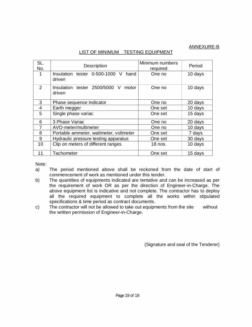
The field testing laboratory to be established by the contractor at his cost shall be equipped with the minimum number of testing equipment as per Annexure-B.
20.0 The following provisions are added to the clause no 69 of GCC wherever applicable:
No claim on account of extra / substituted / variation of items etc. pertaining to the
contractor’s portion of work save and except what is admitted and paid by Owner,
shall be entertained or admitted by EPI. Any claim by the contractor, if not paid by
the Owner, whatsoever be the reason shall not be admitted by EPI. EPI’s decision
in this respect shall be final and binding on the contractor. But under no
circumstances contractor shall suspend the work on the non-settlement of rates
under this clause.
Further the quantities given in the Price Bid/ Bill of Quantity can individually or
collectively vary up to ± 20% of the contract price without any change in the rates.
21.0 Recovery for delay in completion :
In case the project execution is delayed beyond the contractual scheduled
completion period due to reason attributable to the contractor, the staff and site
office expenses of EPI for extended period shall be paid by him to EPI at the rate

Page 14 of 19
of Rs. 10,000/- per month. This shall be in addition to the facilities provided by the
contractor to EPI and the other recoveries, if applicable as per clause no 72
(including its sub clauses) of GCC and Penalties etc. if any, levied by Owner for
the works pertaining to the contractor’s scope of work.. The decision of EPI in this
regard shall be final & binding on the party.
22.0 Responsibility of materials
The contractor shall be responsible for obtaining all approvals from Owner with
regard to quality of materials & workmanship and measurements etc. for their
portion of work. All such approvals shall be in the name and title of EPI. The
contractor shall be responsible for reconciliation of issued material with
Owner/EPI, if any, and the contractor shall make arrangements for safe up
keeping / custody of the material and final reconciliation is also to be done by the
contractor. In case there is any shortfall of any issued items during reconciliation,
recovery at double the cost of materials prevailing at that time of recovery shall be
made from the contractor’s due payment.
23.0 Dealing with Owner etc
The contractor will not deal directly with Owner and all the correspondence in
matters regarding bills, claims, interpretation of the specifications, conditions and
all matters related to the contract with Owner, Owner’s Consultants, all other
agencies including Government and Statutory bodies etc. shall be done through
EPI only. The contractor shall prepare and submit expeditiously all bills, claims,
details, clarifications, documents, information, etc. as required by EPI/ Owner for
proper execution and successful completion of the “Works”.
24.0 Interpretation
Issues related to interpretation and claims, if any, related to the contractor’s scope
of work, arising out of contract between EPI and Owner shall be referred with full
justification by the contractor to EPI for settlement with Owner including arbitration
with Owner, if inescapable, and outcome of such a settlement shall be binding on
the contractor. EPI at its option may associate the contractor in the above process

Page 15 of 19
of settlement for his portion of work. The cost & expenses on arbitration with
Owner shall be shared by EPI and the contractor in proportion of his offer and
EPI's mark up towards its overheads & profits. In case the award/settlement with
the Owner is in favour of EPI, ninety percent of the award/settlement amount shall
be shared between EPI and contractor in proportion of contractor’s contract price
with EPI and EPI's mark up towards its overheads & profits. The balance ten
percent of the award/settlement amount shall be retained by EPI towards its
administrative charges. In case the award/settlement is against EPI, the entire
damages/counterclaims imposed, if any, shall be borne by the contractor alone
and the contractor shall have no claim whatsoever against, EPI in such a
settlement. Further, EPI shall have no liability towards any claim of the contractor,
which is not paid by the Owner.
25.0 No claim for non-approval
In case of non-approval of contractor’s association for the Project by the Owner
and/or by EPI due to any reasons whatsoever at any stage of the “Works”, the
contractor shall have no claim on EPI.
26.0 Inspection and responsibility
The work executed by the contractor shall be subject to audit and quality control
checks from Quality Control Division & Technical Audit of EPI, Owner, and
Inspecting Agency of the Owner and Chief Technical Examiner of Central
Vigilance Commission, Govt. of India. In the eventuality of any defect/ substandard
works as brought out in the report or noticed otherwise at any time during
execution, maintenance period etc., the same shall be made good by the
contractor without any cost to EPI. In case the contractor fails to rectify the
defect/sub-standard work within the time period stipulated by EPI, EPI shall get it
rectified at the risk and cost of the contractor and shall recover the amount from
the dues of the contractor.

Page 16 of 19
27.0 Actions for false information EPI has agreed to associate the contractor on the basis of details regarding his
experience profile, financial standing, credentials, fulfilment of statutory
obligations, etc. by him to EPI. In case, at a later stage if it is found that the
contractor has submitted incorrect, false details and credentials resulting in
apprehensions on the capabilities of the contractor with regard to quality & timely
completion of works, financial capabilities etc, EPI can terminate this order solely
at its option. In this eventuality the contractor shall be liable for the losses suffered
by EPI and further the contractor shall have no claim on EPI, whatsoever.
28.0 Non-applicability of concessions or exemptions
However, if EPI is granted some concession or exempted from certain obligations
by Owner, by virtue of EPI being a Public Sector Company, the same concessions
/ exemptions shall not be applicable to the contractor. The decision of EPI in this
regard including interpretation of terms & conditions shall be final & binding on the
contractor.
(Signature and seal of the Tenderer)

Page 17 of 19
ANNEXURE-A
LIST OF MINIMUM TOOLS, PLANT AND MACHINERY SL. No. Description Minimum numbers
required Period
1 Portable Grinder (Electric ) Two nos. As and when instructed 2. Portable Welding Machine Two nos. -do- 3. DG Set 10 KVA (Minimum) One no 15 days 4. Portable Gas Cutting Sets with
hoses and regulator Two nos. As and when instructed
5. Pipe Threading Machine Two nos. -do- 6. Pipe Bending Machine
(Hydraulic) One no -do-
7. Portable Drilling Machine suitable for drilling of different sizes
Two nos. -do-
8. Power Hacksaw One no. -do- 9. Hydraulic Crimping Machine One no. -do- 10. Hand Crimping Tools Two nos. -do- 11. Portable Electric Blowers Two nos. -do- 12. Portable Vacuum Cleaners Two nos. -do- 13 Plate/sheet cutting machine,
Bending Machine Two sets. -do-
14 Hoisting lift for materials with winch One set 25 days
15 D-spanners, Ring spanners, box spanners etc of assorted size
As required -do-
16 Cutting, twisting and combination pliers Three nos. 10 days
17 Screw drivers-both star headed and plain headed of different sizes
Two sets As and when instructed
18 Slide wrench, pipe wrench etc -do- -do- 19. Auto level & staff One
-do- 20 Hand tools for
plumbing/plaster/concrete cutting/Tile cutting etc.
Lot -do-
Note:
(a) The period mentioned above shall be reckoned from the date of start of commencement of work as mentioned under this tender. (b) The quantities and list of equipments indicated are tentative and can be increased
/amended as per the requirement of work OR as per the direction of Engineer-in-Charge. The above equipment list is indicative and not complete. The contractor

Page 18 of 19
has to deploy all the required equipment to complete all the works within stipulated specifications & time period as contract documents.
(c) The contractor will not be allowed to take out equipments from the site without the written permission of Engineer-in-Charge.
(Signature and seal of the Tenderer)
Page 19 of 19
ANNEXURE-B LIST OF MINIMUM TESTING EQUIPMENT
SL. No. Description Minimum numbers
required Period
1 Insulation tester 0-500-1000 V hand driven
One no 10 days
2 Insulation tester 2500/5000 V motor driven
One no 10 days
3 Phase sequence indicator One no 20 days 4 Earth megger One set 10 days 5 Single phase variac One set 15 days
6 3 Phase Variac One no 20 days 7 AVO-meter/multimeter One no 10 days 8 Portable ammeter, wattmeter, voltmeter One set 7 days 9 Hydraulic pressure testing apparatus One set 30 days
10 Clip on meters of different ranges 18 nos. 10 days
11 Tachometer One set 15 days
Note: a) The period mentioned above shall be reckoned from the date of start of commencement of work as mentioned under this tender. b) The quantities of equipments indicated are tentative and can be increased as per the requirement of work OR as per the direction of Engineer-in-Charge. The above equipment list is indicative and not complete. The contractor has to deploy all the required equipment to complete all the works within stipulated specifications & time period as contract documents. c) The contractor will not be allowed to take out equipments from the site without
the written permission of Engineer-in-Charge.
(Signature and seal of the Tenderer)

Page 1 of 30
TECHNICAL SPECIFICATION INTERNAL WORKS All the works shall be done as per the specifications as under. In case the specification of any particular item is not given, the same may be done as per the latest CPWD Specifications and Indian Standards, The Decision of the Engineer In Charge will be final in such case.
DISMANTLING AND DEMOLISHING
1. IS 1200 (Pt – XVIII) Method of Measurements of Building and Civil Engineering Works
(Part –XVIII) Demolition and Dismantling
2. IS 4130 Demolition of Buildings–Code of Safety
TERMINOLOGY
(i) DISMANTLING: The term ‘Dismantling’ implies carefully separating the parts without damage and removing. This may consist of dismantling one or more parts of the building as specified or shown on the drawings.
(ii) DEMOLITION: The term ‘Demolition’ implies breaking up. This shall consist of demolishing whole or part of work including all relevant items as specified or shown on the drawings.
SCOPE OF WORK:
The work envisaged under this sub- head is for dismantling and demolition of brick masonry in cement/lime mortar, reinforced concrete works, and removing wooden doors, wooden or steel windows.
GENERAL:
The term dismantling implies carefully taking up or down and removing without damage. This shall consist of dismantling one or more parts of the building as specified or shown on drawings.
The term Demolition implies taking up or down or breaking up. This shall consist of demolition whole or part of working including relevant items as specified or shown on drawings.
PRECAUTIONS:
Necessary propping, shoring and/or underpinning shall be provided for safety of the adjoining work or property, which is to be left intact, before dismantling and demolishing is taken up and the work shall be carried out in such way that no damage is caused to the adjoining work or property. Wherever required, temporary enclosures or partitions shall also be provided. Necessary precautions shall be taken to keep the dust- nuisance down as and when necessary. Dismantling shall be commenced in a systematic manner. All materials which are likely to be damaged by dropping from

Page 2 of 30
height or demolishing roofs, masonry etc., shall be carefully dismantled first. The dismantled articles shall be passed by hand where necessary and lower to the ground and not thrown. The materials then be stocked properly as directed by the Engineer – in – charge. All materials obtained from dismantling or demolition shall be the property of the government unless otherwise specified and shall be kept in safe custody until handed over to the Engineer – in – charge. Any serviceable material, obtained during dismantling or demolition shall be separated out and stacked properly as indicated by Engineer – in – charge within a lead of 150m. Or as specified in the item. All under serviceable materials, rubbish etc. shall be disposed of as directed by the engineer in charge.
TREATMENT:
All the dismantled area shall be rendered clean of all debries, dust etc. The sides of jambs, sills, soffits, etc of the openings if any , after taking out doors and windows chowkhats, unless and otherwise to be treated, shall be plastered in CM 1;3 with finishes to render true sides, corners, edges etc.
RATES: The rate shall include cost of all such operations mentioned above including necessary labour , material , transport, scaffolding, staking the serviceable materials, disposing the unserviceable materials within the lead specified, all as directed by the Engineer in charge.
CARPET
Approved make 100% Optimum SD / Wear On Nylon Tufted, Textured Loop Pile carpet tiles of 20 oz/ sq.yd of size 609x609mm permanent static control solution dyed, pile height to a maximum of 0.101 inches with synthetic non-woven Glasbac backing of Vinyl cushion with glass reinforcement / PVC free underscore cushion including colourfastness> or = 4 after 100 hours, moth proof, stain resistant etc. complete, over existing flooring as per Manufacturer's specification. The rate shall be inclusive of the PVC free underscore cushion backing for entire area to be covered by carpet. (Note: Volatile organic compound free adhesive of approved make shall be used for laying the carpet.)
INSTALLATION
FLOOR
A good floor is literally and figuratively the basis for a well-laid carpet. The floor must be completely level (i.e. free of holes, irregularities and remains of old carpets), clean, dry, secure and stable. Seams and cracks between the floor and the floorboards must be sealed with an appropriate sealant to prevent any air flows from leaving dust deposits.
CARPET UNDERLAY
A good underlay is an important aspect of laying a carpet. It ensures increased comfort, luxurious radiance and a longer-lasting, more beautiful appearance of the carpet. Underlay acts as sound

Page 3 of 30
proofing and keeps in warmth, gives a soft feel underfoot and overcomes any slight bumps in floor surfaces. Rubber underlay (including the foam and sponge types) is especially good where you suspect that damp may be a problem, where floorboards are uneven, or where under floor heating is fitted.
LAYING
The carpet underlay is laid on the floor at right-angles to the direction in which the carpet is laid, and fixed in position with a suitable adhesive. When properly applied, a non-slip adhesive provides sufficient adhesive strength and does not leave any residue when the carpet underlay is removed. The floor must therefore be completely level; otherwise irregularities in the floor will show in the carpet.
To install carpet properly, you need to start with a piece that overlaps the edge of the floor by about 4 inches. The overlay can be trimmed later so the carpet fits properly. To cut your first section, measure the room at its longest point and add 4 inches to that measurement. The carpet is glued to the underlay with a suitable adhesive. Due to the drying time of the adhesive, gluing is done in sections until the entire carpet has been stuck down. After the carpet has been glued in position, wait for a while before putting any furniture in place to avoid permanent indents. The carpet must be rolled with a laying roller. The time required for this is indicated by the manufacturer of the adhesive and must be observed. Please observe the manufacturer’s guidelines on the quantity of adhesive to be applied and ventilation times. Foam backed carpet does not need to be stretched. Foam-backed carpets should never be laid directly onto polished, varnished or vinyl floors or they will stick permanently.
JOINING OF CARPETS
If your room is wide enough that you need put another piece of carpet, follow the same processwith the second piece - measure, mark and trim. Be sure the carpet pile is running the same way in all pieces, and that the carpet you cut is large enough to overlap the wall by about 4 inches, as well as overlapping the first piece of carpet by 4 inches. Try to layout your carpet pieces so the seams won't be in noticeable position or in high traffic areas. Where the carpet pieces will join, overlap the two pieces, and then cut through both pieces of carpet using an electric carpet cutter, glued the gap and fix ensuring the edges will match exactly.
CARPET CARE AND MAINTENANCE
Clean Carpet before it gets dirty and vacuum on a regular basis to making Carpet last years longer. Install Carpet properly. Choose the correct padding, with the wrong pad carpet could develop waves and wrinkles, the backing could fall apart or it could begin to wear out and mat down quickly in all the

Page 4 of 30
main walkways. Remove stains using water and a wet/dry vacuum. Have carpet professionally cleaned every 12 to 18 months depending on the traffic level and how often you vacuum it.
ENGINEERED WOOD FLOORING
Providing and supplying Engineered Wood Flooring, with four side micro beveled. Planks would be 120 mm wide and in random length comprising of 5 ply including top veneer with a total thickness of 10.5 mm available in species of Teak/ Hickory/ Sapele/ Oak/Distressed Hickory Brandywine/Distress Antique Natural and respectively. The top 2mm veneer / laminate Finish.
INSTALLATION: It is important to ensure the sub floor on which the planks are being laid is smooth, flat & hard & free from moisture, grease, etc. In case of uneven sub floor the same should be leveled by self leveling compound. The moisture level present in the subfloor should be less than 8% before installation of the floor.
The Engineered hardwood should be a completely floating floor (using recommended a water barrier of minimum of 250 microns and 2mm polyethylene foam). The tongue and groove joints shall be glued together using recommended adhesive.
The installation shall be undertaken as per the manufacturer’s installation instructions.
STORAGE & HANDLING:
The material has to be handled and unloaded with care. It has to be store in a dry place being sure to provide at least a four-inch air space under cartons which are stored upon “on-grade” concrete floors. Flooring should not be delivered until the building has been enclosed with windows, doors are in place and cement work and plastering and all other “wet” work is completed and dry.
PREPARATION:
All concrete, masonry, framing members, drywall, paint and other “wet” work should be thoroughly dry. The wall coverings should be in place and the painting completed except for the final coat on the base molding. When possible, delay installation of base molding until flooring installation is complete. Basements and crawl spaces must be dry and well ventilated.
SUB FLOOR CONDITIONS:
• CLEAN—Subfloor must be free of wax, paint, oil, sealers, adhesives and other debris. • LEVEL/FLAT—Within 3/16” in 10’ (5 mm in 3 m) and/or 1/8” in 6’ (3 mm in 2 m). If the floor is not
leveled an underlayment using self leveling compound shall be done.

Page 5 of 30
• Underlayment Additive: Follow the instructions of the leveling compound manufacturer but make certain the leveling compounds are completely DRY before beginning installation. Leveling materials must provide a structurally sound subfloor that does not affect the holding power of the fastener.
• DRY—Check and document moisture content of the subfloor using the appropriate moisture test. Concrete subfloors must be a minimum of 30 days old before testing begins.
• STRUCTURALLY SOUND—Nail or screw any areas that are loose or squeak. Wood panels should exhibit an adequate fastening pattern, glued/screwed or nailed as system requires, using an acceptable nailing pattern. Flatten edge swell as necessary. Replace any waterdamaged, swollen or delaminated subflooring or underlayment.
DOORWAY AND WALL PREPARATION
• Undercut door casings and jambs. Remove any existing base, shoe mold or doorway thresholds. These items can be replaced after installation. All door casings and jambs should be undercut to avoid difficult scribe cuts.
ESTABLISHING A STARTING POINT
• Installation parallel to the longest wall is recommended for best visual effects, however, the floor should be installed perpendicular to the flooring joists unless the subfloor has been reinforced to reduce subfloor sagging.
INSTALLING THE UNDERLAYMENT:
• The underlayment should be installed in the same direction that the hardwood flooring. • The underlayment should be extended a few inches up the wall. • Excess underlayment should be cut prior to installing trim or moldings.
INSTALLATION:
• Floor should be installed from several cartons at the same time to ensure good color and shade mixture.
• When possible, preselect and set aside boards that blend best with all horizontally mounted moldings (reducer/stair nose, etc.) This will ensure a uniform final appearance. Install these boards adjoining the moldings.
• When installing as a linear pattern be attentive to staggering the ends of the boards at least 4”–6” (10–15 cm) when possible, in adjacent rows. This will help ensure a more favorable overall appearance of the floor.
• Avoid staggering the rows uniformly to prevent stair-stepping. Boards cut from the opposite end of the row may be used for the next starter boards.

Page 6 of 30
• Always allow a minimum ¼” (6 mm) expansion around all vertical obstructions. Allow ½” (13 mm) for floating floors.
• Select the first board. All installations should begin with the groove side against the wall using the longest boards available. Apply a continuous 1/8″(3 mm) glue bead to the inside bottom of the groove on the end of the board. Do not apply glue to the groove side at this time. Products with the end tongue on the left should be installed right to left, opposite tongues should be left to right. If a sacrificial board was used DO NOT glue the first row to it.
• Complete the first row. Cut the last board allowing for 1/2″(13 mm) clearance between the wall and the floor. (Use the remaining end of the cut board as a starter board for any row following row three). Install a wedge on the end of the board between the hardwood flooring and the wall allowing 1/2″(13 mm) expansion space. Avoid installation of any boards shorter than 16″(40.6 cm) in the first four rows.
• Use a pull bar to pull the last board into place from the opposite end. Install wedges into the gap and tighten
• If any glue gets on the surface of the flooring, wipe off immediately with a clean damp cloth. • Cut or use a shorter board for the first board of the second row. Start the second row by applying a
1/8″(3 mm) bead along the inside, bottom of the end and side groove of the new board. Install the first board of row two. Apply a bead of glue to the inside bottom of the end and side groove of the next board and install. When installing boards together, use a tapping block against the tongue, not the groove. Tap the boards into place by tapping with a hammer on the tapping block. DO NOT tap on the edge directly with the hammer. Complete the second through fourth rows using this technique. Insert wedges on the ends, as necessary, to restrain the movement of the floor.
• In the remaining rows, stagger joints 4″–6″(10–15 cm) apart. Install the rest of the floor. Be sure all joints are tight. Use spacers on the long and butt walls. Use a pull bar to tighten the joints from the ends.
COMPLETING THE INSTALLATION:
• All tape should be removed and the floor should be cleaned with the recommended hardwood flooring cleaner.
• Any transition pieces that may be needed should be installed or uninstalled such as Reducer Strips, T-moldings, or Thresholds. The products are available pre-finished to blend with your flooring.
• All underlayment (floating only) should be cleaned and any transition pieces, reducer strips, T-moldings if necessary, should be installed or uninstalled. Thresholds, bases and/or quarter round moldings that may be needed.
MODE OF MEASUREMENT:
The mode of measurement is per Sqmt of plan area.

Page 7 of 30
FALSE FLOORING ACCESS FLOOR SYSTEMS
SYSTEM: Access floor system to be installed shall provide a maximum finished floor height of 600mm from the existing floor level. The system shall provide for suitable pedestal and understructure designed to withstand various static loads and rolling loads subjected to it in an server / DCS / panel / rack area. The entire Access floor system shall provide for adequate fire resistance, acoustic barrier and air leakage resistance.
Panels: Panels shall be made from steel. The bottom of the panel shall be embossed in 49 hemispherical shape of 60mm dia and 12 reverse conical of 25mm dia to give strength and flexural rigidity. The top sheet shall be plain and resistant welded at various locations after the top and bottom sheets have been degreased and phosphated. The above hollow panel shall have an infill of light weight cementations material. The entire panel shall be coated with epoxy coating on the exposed surface. Panels shall remain flat through and stable unaffected by humidity or fluctuation in temperature throughout its normal working life.
Panels shall provide for impact resistance top surfaces minimal deflection, corrosion resistance properties and shall not be combustible or aid surface spread of flame. Panels shall be insulated against heat and noise transfer. Panels shall be 600 x 600mm fully interchangeable with each other within the range of a specified layout. Panels shall rest on the grid formed by the stringers which are bolted on to the pedestals. Panels shall be finished with anti-static Laminate of colour and PVC beading / trimming along the edges.
PEDESTALS: Pedestal installed to support the panel shall be suitable to achieve a finished floor height of 75 to 600mm. Pedestal design shall confirm speedy assembly and removal for relocation and maintenance.Pedestal base to be permanently secured to position on the sub floor. Pedestal assembly shall provide for easy adjustment of levelling and accurately align panels to ensure lateral restrain. Pedestals shall support an axial load of 2000 Kgs, without permanent deflection and an ultimate load of 3500 Kgs. Pedestal head shall be designed to avoid any rattle or squeaks
PEDESTAL ASSEMBLY: Consisting of 100 x 100 x 2mm thick galvanized epoxy polyester coated MS Base plate die-pressed orbit ally riveted to a 21mm. O.D. 2.5mm thick epoxy coated MS pipe to engage the pedestal head assembly. The pedestal head assembly consists of an embossed steel plate having 4 holes with ¼ th tapping for fastening and locating of tile; orbit ally riveted to a corresponding threaded stud 16mmdia. (O.D), length 100mm which is designed to engage the pedestal base assembly. The assembly shall provide a range of height adjustment up to 25mm, with the help of check nuts.
UNDER STRUCTURE: Under structure system consists of stringers of size 575 x 30x 20 x 1.5mm to form a grid of 600 x 600mm. These stringers are locked into the pedestal head and run both ways. The US system shall provide adequate solid, rigid and quiet support for access floor panels. The US system shall provide a minimum clear, uninterrupted height of 550 mm between the bottom of the floor and bottom of the access floor for electrical conduiting and wiring.

Page 8 of 30
STRINGERS: Stringer system is all steel construction, rectangular channels 30 x 20 x 1.6mm thick with pre-punched counter sunk holes at both ends for securing the stringers onto the pedestal head ensuring maximum lateral stability in all directions. The grid formed by the pedestal and stringer assembly shall receive the floor panel.
LIFTING HOOK - 2 Nos shall be given to HPCL free of cost and necessary cutting for supply/return Air Grills and for Grommet of required size, of for electrical supply wires wastages, lead & lift, grouting the system with anchor fastener, removing all debris from the premises etc. complete, as directed shall be in the scope of the work.
VITRIFIED TILES FLOORINGAND DADOING
MATERIALS
Tiles shall be matching with existing tiles or any equivalent, fully vitrified with high gloss polished surface. The surface hardness of the tiles shall be min 7 on moh’s Scale. The thickness of tile shall be min 9 mm for 400mmsq tile &shall be min 12mm for large tiles of 900mm sq.Tiles shall be true to shape &shall have sq edge. The surface shall be perfectly in level. Bent tiles or tiles with variation in dia shall not be used.Morter shall be cement mortar 1:4.Slurry shall be neat cement paste of money like consistency.
WORKMANSHIP
The tile pattern shall be first established and approved by the Engineer-in-charge/Architect. Internal cut pieces shall not be permitted. If the area where the tiles are to be laid is not perfect Rectangle or Square, the different shall be adjusted at edges away from the visible or open areas in consultation with the Architect /Engineer in charge. Diagonal Pattern in such areas may be permitted. In case of irregular shaped areas & where diagonal Pattern is provided, extra care shall be taken to fix angular tile pieces.
Tiles with chipped off Surface Finish shall not be used. Entire tile work shall be protected by laying over it a thick layer of Gypsum plaster or loose full size plywood boards.
MODE OF MEASUREMENTS AND PAYMENT
The rate shall be for a unit of m2 and clear visible area shall be measured.The rate shall include for all materials, labour and edge polishing, sundry involved in operation of the above specified item.
FIBRE CEMENT BOARD DRY WALL PARTITION
Providing and fixing of ready for primer and paintable surfaced 72mm drywall partition using non asbestos, non combustible, fibre cement boards made of recycled fibres and cement as raw materials manufactured by wet recessed autoclaved technology with density of 1300Kg/m3 as per (ASTMC

Page 9 of 30
1185). The G.I. frame of thickness 0.60 consists of steel metal stud frame of size 50mm having one flange of 41mm and other of 44mm placed @ every 600 mm c/c in vertical direction upto soffit and horizontally at board joints.These studs are to be placed at floor and ceiling channels of 52mm width and 0.60 mm thick and having equal flanges of 32 mm. The floor and ceiling channels are fixed to floor and soffit using fasteners at every 600mm c/c. A horizontal frame section is placed at every 1200mm c/c. Next one layer of 10mm thick fibre cement board are fixed in staggered joints on either side of the studs to avoid leakage through joints. These boards are joined using Specified “type S” Self tapping SS W 25 / 3.5 x 25mm corrosion resistant drywall steel screws spaced at 200mm centers on all joints and 300mm centers in the field of boards. Screw fixing is done mechanically. Finally, boards and screw heads are to be jointed and finished with epoxy putty so as to have a flush look which includes filling tapered edge and square edges of board with cement based joining compound and fibre tape .
Toughened GLAZING:
Glass used for Toughened glazing shall be float glass of best approved quality free from flaw, specks, bubbles and shall be of thickness specified in the Schedule of Quantities.
All glass to be of approved manufacturer complying with I.S. 3548-1966 as per approved quality and sample to be of the selective qualities specified and free from bubbles, smoke, air holes and other defects. Polished plate glass shall be "glazing glass" (G.G.) conforming to IS 3438-1965 or as per approved sample and quality.
The compound for glazing to metal is to be a special non-hardening compound manufactured for the purpose and of a brand and quality approved by the EPIL /Architects.
While cutting glass, proper allowance be made for expansion. Each square of glazing to be in one whole sheet. On completion of work clean all glass inside and out, replace all cracked scratched and broken panes and leave in good condition.
FLUSH DOORS:
All flush doors shall be solid core unless otherwise specified. It shall conform to the relevant specifications of I.S.2202 and shall be obtained from approved manufacturers. The finished thickness of the shutter shall be as mentioned in the item. Face veneers shall be of the pattern and colour approved by the EPIL / Architects and an approved sample shall be deposited with the EPIL/ Architects for reference.
The solid core shall be of Wood Laminate prepared from battens of well-seasoned and treated good quality wood having straight grains. The battens shall be of uniform size of about 2.5 cm width. These shall be properly glued and machine pressed together with grains of each piece reversed from that of adjoining one. The longitudinal joints of the battens shall be staggered and no piece shall be less than 50 cm in length. Alternatively, the core shall be of solid teak particle board. Edges of the
Page 10 of 30
core shall be lipped with first class teakwood battens of 4 cm. ( 1 ½”) minimum depth, glued and machine pressed along the core.
The core surface shall then have two or three veneers firmly glued on each face. The first veneer (called cross Bond) shall be laid with its grains at right angles to those of the core and the second the third veneer with their grains parallel to these of the core. The under veneers shall be of good quality, durable and well-seasoned wood. The face veneer shall be of minimum one mm thickness and of well-matched and seasoned first class teak, laid along with grains of the core battens. The combined thickness of all the veneers on each face shall not be less than 4 mm. Thermo setting synthetic resin conforming to IS 303 for moisture proof plywood grade M.P.F.I. shall be used in manufacture. In addition all doors shall have external lipping all round 8 mm thick.
STEEL FRAME WITH FIRE DOOR SHUTTERS GENERAL INDIAN STANDARDS Work shall be carried out to Indian Standards and Code of practices. In absence International standards shall be followed. These shall be latest issue. List given hereunder is not to be considered as conclusive and is for reference and guidance only. Any discrepancies / conflict noticed shall be directed to the PM for his direction / approval. However as a general rule more stringent specification shall take precedence. QUALITY ASSURANCE 1 Material used shall conform to IS. It shall withstand stresses and strains to which it is subjected. 2 Fabrication, assembly, erection, fastening, etc. shall be in accordance to details approved by PM. 3 Manufacturer shall have minimum five years experience in these products. Works shall be carried
out under qualified supervisions. SUBMITTALS. PRODUCTS
a) The contractor shall submit detailed catalogues, literature for products proposed to be used by him. He shall submit detail comparison for properties, test etc specified in BOQ and those of products he intends to use. b) Certificate of manufacturer of products that it conforms or exceeds specification given in contracts and its suitability for use. c) Manufacturer and the contractor shall give guarantee for performance and durability.
SHOP DRAWING The contractor shall submit including required designing shop drawing for doorframes, shutters complete with
• a) Plan, elevation with relative position of adjacent works • b) Details of tracks, guides, rollers, hood, locking arrangement

Page 11 of 30
• c) Full size details with specification of materials, sizes spacing of welds, screws bolts, rivets, anchors etc.
• d)Construction, fabrication and erection details • e) Glazing details with type size and fixing • f) Fitting and fixtures with type size, brand and fixing details. • g) Finishing details
SAMPLES: Samples of following shall be submitted along with submittals Frame corner 300 x 300 mm with corner construction and finish Shutter frame corner with inner construction details, stiffening, its welding, riveting, bolting, insulation etc. Glazing with method of fixing, PVC / neoprene beadings, GI anchors, Fittings and fixtures MATERIALS
GALVANIZED STEEL Welding electrodes used shall confirm to respective IS Bolts, Bolts conforming to IS 1367 shall be used. Bolts may be turned and fitted or black bolts. Bolts, nuts shall be free from excessive rust, scaling/pitting, crack or any other defects. They shall be with sharp, defined threads and heads. They shall be well protected and securely stored at site.
ELECTRODES Covered welding electrodes conforming to IS 814 shall be used in metal arc welding. Electrodes shall be fresh and packed in watertight packing as received from manufacturers with date of manufacture. They shall be stored in damp proof store.
FITTINGS AND FIXTURES Fittings and fixtures shall be with IS mark and as required for respective locations. Thickness, size shall be as specified and the contractor shall ensure that material withstands the type of loading they are subjected to finishing of fittings and fixtures shall be in conformity to specification. Also it shall be noted that fitting and fixtures material are compatible and no harmful electrolytic / anodic actions are likely to take place. Screws, bolts, nuts etc shall be compatible with fitting and fixtures provided. DELIVERY, STORAGE AND HANDLINGS. Fabricated products shall be handed over and transported to site with precautions not to damage, bend, dent, sag etc.
Page 12 of 30
Fabricated finished product shall be received with self-adhesive protective coating prior to being transported to site. Store all material is dry, lockable ventilated place. Material shall be placed on runners/packing and they are off the ground minimum 150mm.Inspect material received for dimension, quality and finish. Replace all damage materials immediately. All acceptable material shall be repacked and stored. Special care shall be taken to store glass.
SCOPE OF WORK Providing, designing, drawing, fabricating, shifting and installation of steel door frames and shutters and shutters with accessories such as anchorage, fittings, fixtures finishing etc complete as per specification, conforming to IS and as accepted and approved by the PM to his entire satisfaction. Item proposed under this shall be Pressed sheet metal door frame Pressed metal sheet shutters
WORKMANSHIP GENERAL Fabrication shall be carried out only after approval to shop drawings by PM. Work shall be carried out at factory and shall be with proper tools and tackles and complying to Engineering practices. Factory shall be accessible to Architect's and PM's representative at all times. Points to be noted are
CUTTING Cut shall be by sawing, shearing or blanking. Flame cutting shall be avoided. However if permitted, cut edges shall be ground back to clean, smooth edges. Cut shall be accurate, clean, sharp, square and free of burrs, without deforming adjacent surfaces of metals.
HOLES Holes shall be drilled or cleanly punched to achieve accurate, clean, neat and sharp without deforming adjacent surfaces of metals. Gas cutting of hole not permitted.
JUNCTIONS / ASSEMBLY Connections and junctions shall be located as approved in drawings. Connections shall be tight joints capable of developing full strength within members. Joints and connections shall be flush unless specified differently. In exposed condition where required water draining arrangement shall be provided. Provision for thermal movement jointing shall be provided at locations approved by the Architect.
WELDING Welding shall be in accordance with recommendations of the Indian Standard code of practice. Welder shall be trained and certified as per IS 817. Work shall be done with electrodes and/or
Page 13 of 30
methods recommended by the manufacturers of the metals being welded. Welds shall be continuous, except where spot welding is specifically permitted. Exposed welds shall be finished free of imperfections such as pits, runs, splatter, cracks, wrapping, dimpling, depressions or other forms of distortion, discoloration. Exposed welds shall be ground flush and dressed smooth to match adjoining surfaces.
BOLTS AND SCREWS Threaded connections shall be with tight threads entirely concealed. At exposed locations lock nuts, bolts and screw heads, shall be flat and countersunk. Cut off projecting ends of exposed bolts and screws flush with nuts or adjacent metal.
SITE FIXING Work shall include providing and fixing nonferrous anchor bolts / insert plates, plates or other anchoring devices for fixing into or to concrete, masonry or other trades of work. All these shall be with approval of the Architect and the Engineer.
FINISHING Work shall be clean, free from dirt, stains, grease, scratches, distortion, waves, dents, buckles, tool marks, burrs, etc. and defects which mar appearance of finish work.
MOCKUP SAMPLES The contractor shall prepare mockup samples as per approved shop drawing. Mockup samples shall be to full size and shall be true representation of actual works to be carried out at site.
JOINERIES
PLYWOOD
Marine plywood shall generally conform to I.S.710-1980 or latest, bonded with phenol formaldehyde, treated with wood preservative.
TEAK WOOD
Timber shall be well seasoned and of the best quality, Indian Teak of specified (viz). Bandeli, Ballarshah, Malabar, etc.
Timber shall be considered as well seasoned, if its moisture content does not exceed the following limits.
(i) Timber for frames ... 14%

Page 14 of 30
(ii) Timber for planking, Shutters, etc. ... 12%
The moisture content of timber shall be determined according to method described in Paragraph 4 of IS: 287 for 'Maximum Permissible Moisture content of Timber used for different purposes in different climatic zones'.First Class Indian Teakwood means locally available best quality and well seasoned. It shall have uniform color, reasonably straight grains and shall be free from large loose dead knots, or defects of any kind. No individual hard and sound knot shall be more than 2.5 cm. in diameter and aggregate area of all knots shall not exceed 1% of the area of the piece. There shall not be less than growth rings per 2.5 cm. width.
All the wood shall be properly seasoned, natural growth and shall be free from worm holes, loose or dead knots cracks, shakes, twists, bends, sapwood or other defects, saw die square and shall not suffer warping, ting or other defects. All internal frame work shall be treated with approved wood preservative. All wood brought to site should be clean shall not have any preservative. All rejected decayed, bad quality wood shall be immediately removed from site. All wood brought to site must be stacked-stored properly as per instructions.
WOOD WORK:
Timber used shall confirm to specifications described under materials, shall be in accordance with the drawing in every detail and all joiner's work shall be accurately set out, framed and finished in a proper workman like manner. Frames of partitions and opening, etc., shall be of accurately planned smooth and rebates, rounding and mouldingsshall be made as shown on the drawings. Patching or Plugging of any kind shall not be allowed. Joints shall be simple, neat and strong. Framed joints shall be coated with suitable adhesive like glue or synthetic resin before the frames put together. All mortise and tenon joints shall fit in fully and accurately without wedging or filling. The joints shall be pinned with hardwood or rust resisting star shaped metal pints of 8 mm dia., after the frames are put together and pressed in position by means of a press. The frames shall be protected during the progress of work by providing suitable boxing. All portions of timber abutting against or embedded in masonry or concrete shall be treated against termites by giving a coat of any approved wood preservative. All T.W.work should be painted with a coat of approved wood primer.
Frames and Shutters shall not be painted or erected before being approved by the EPIL / Architects.
JOINERY: Joinery is to be prepared immediately after the placing of the Contract framed up, bonded and waged up. Any portions that are warped or found with other defects are to be replaced before wedging up. The whole of the work is to be framed and finished in a workmen-like manner in accordance with the detailed drawings wrought and whenever required, fitted with all necessary metal ties. Straps, belts, screws, glue etc. Running beaded joints are to be cross-tongued with teak tongues wherever 1(1/2) thk. Double cross tongued. Joiners work generally to be finished with fine sand/glass paper.

Page 15 of 30
Joints: All joints shall be standard mortise and tenon, dowel, dovetail, and cross halved. Nailed or glued but joints will not be permitted, screws, nails etc. will be standard iron or wire of oxidized Nettle fold tenons should fit the mortises exactly.
Nailed or glued butt joints will not be permitted, exceptional cases with approval of Architects/EPIL.
Where screws shown on a finished surface, those will be sunk and the whole plugged with a wood plug of the same wood and grain of the finished surfaces will be neatly punched and the hole filled with wood filler to match the colour.
Should joints in joiner's work open, or other defects arise within the period stated for defect liability in the contract and the clause thereof be deemed by the Architects to be due to such defective joinery shall be taken down, and refilled, redecorated and/or replaced if necessary and any work disturbed shall be made good at the Contractor's expense.
Nails, spikes and bolts shall be of lengths and weights approved by the HPCL/Architects. Nails shall comply with IS 1959-1960. Brass headed nails are to comply with B.S.1210. Wire staples shall comply with B.S.1494 or equivalent.
The contact surface of dowels, wedges etc., shall be glued with an approved adhesive.
Where glued, joinery and carpentry work is likely to come into contact with moisture; the glue shall be waterproof grade.
• IS 226 Structural steel (Standard quality) superseded by IS 2062:1992 • IS 277 Specification for galvanized steel sheets • IS 1038 Specification for steel doors, windows and ventilators • IS 1081 Code of practice for fixing and glazing of metal (steel &aluminium) door, windows
and ventilators
• IS 1361 Specification for steel windows for industrial buildings • IS 1367 (Part 1-19) Technical supply conditions for threaded steel fasteners • IS 1977 Sturctural steel (ordinary quality) • IS 2062 Steel for general structural purposes • IS 4351 Specification for steel door frames • IS 4736 Hot - dip zinc coating on mild steel tubes

Page 16 of 30
FLUSH DOORS:
All flush doors shall be solid core unless otherwise specified. It shall conform to the relevant specifications of I.S.2202 and shall be obtained from approved manufacturers. The finished thickness of the shutter shall be as mentioned in the item. Face veneers shall be of the pattern and colour approved by the EPIL / Architects and an approved sample shall be deposited with the EPIL / Architects for reference.
The solid core shall be of Wood Laminate prepared from battens of well-seasoned and treated good quality wood having straight grains. The battens shall be of uniform size of about 2.5 cm width. These shall be properly glued and machine pressed together with grains of each piece reversed from that of adjoining one. The longitudinal joints of the battens shall be staggered and no piece shall be less than 50 cm in length. Alternatively, the core shall be of solid teak particle board. Edges of the core shall be lipped with first class teakwood battens of 4 cm. ( 1 ½”) minimum depth, glued and machine pressed along the core.
The core surface shall then have two or three veneers firmly glued on each face. The first veneer (called cross Bond) shall be laid with its grains at right angles to those of the core and the second the third veneer with their grains parallel to these of the core. The under veneers shall be of good quality, durable and well-seasoned wood. The face veneer shall be of minimum one mm thickness and of well-matched and seasoned first class teak, laid along with grains of the core battens. The combined thickness of all the veneers on each face shall not be less than 4 mm. Thermo setting synthetic resin conforming to IS 303 for moisture proof plywood grade M.P.F.I. shall be used in manufacture. In addition all doors shall have external lipping all round 8 mm thick.
WALL PAINTING WITH PLASTIC EMULSION PAINT
The plastic emulsion Paint is not suitable for application on external, wood and iron surface and surfaces which are liable to heavy condensation. These Paints are to be used on internal surfaces except wooden and steel.
Plastic Emulsion Paint as per IS 5411 of approved brand and manufacture and of the required shade shall be used.
PAINTING ON NEW SURFACE
The surface shall be thoroughly cleaned. All unevenness shall be rubbed down smooth with sand paper and shall be well dusted. Knots, if any shall be covered with preparation of red lead made by grinding red lead in water and mixing with strong glue sized and used hot. Appropriate filler material conforming to IS 345 with same shade as Paint shall be used where specified. The surface treated for knotting shall be dry before Paint is applied. After obtaining approval of Engineer-in-Charge for wood work, the priming coat shall be applied before the wood work is fixed in position. After the

Page 17 of 30
priming coat is applied, the holes and indentation on the surface shall be stopped with glazier’s putty or wood putty. Stopping shall not be done before the priming coat is applied as the wood will absorb the oil in stopping and the latter is therefore liable to crack.
APPLICATION: The number of coats shall be as stipulated in the item. The Paint will be applied in the usual manner with brush, spray or roller. The Paint dries by evaporation of the water content and as soon as the water has evaporated the film gets hard and the next coat can be applied. The time of drying varies from one hour on absorbent surfaces to 2 to 3 hours on nonabsorbent surfaces. The thinning of emulsion is to be done with water and not with turpentine. Thinning with water will be particularly required for the under coat which is applied on the absorbent surface. The quantity of water to be added shall be as per manufacturer’s instructions.
The surface on finishing shall present a flat velvety smooth finish. If necessary more coats will be applied till the surface presents a uniform appearance.
PRECAUTIONS
(a) Old brushes if they are to be used with emulsion Paints, should be completely dried of turpentine or oil Paints by washing in warm soap water.
Brushes should be quickly washed in water immediately after use and kept immersed in water during break periods to prevent the Paint from hardening on the brush.
(b) In the preparation of wall for plastic emulsion painting, no oil base putties shall be used in filling cracks, holes etc.
(c) Splashes on floors etc. shall be cleaned out without delay as they will be difficult to remove after hardening.
(d) Washing of surfaces treated with emulsion Paints shall not be done within 3 to 4 weeks of application.
PAINTING ON OLD SURFACE
The surface shall be thoroughly cleaned. All unevenness shall be rubbed down smooth with sand paper and shall be well dusted. Knots, if any shall be covered with preparation of red lead made by grinding red lead in water and mixing with strong glue sized and used hot. Appropriate filler material conforming to IS 345 with same shade as Paint shall be used where specified. The surface treated for knotting shall be dry before Paint is applied. After obtaining approval of Engineer-in-Charge for wood work, the priming coat shall be applied before the wood work is fixed in position. After the priming coat is applied, the holes and indentation on the surface shall be stopped with glazier’s putty
Page 18 of 30
or wood putty. Stopping shall not be done before the priming coat is applied as the wood will absorb the oil in stopping and the latter is therefore liable to crack.
The surface before application of Paint shall be flattened well to get the proper flat velvety finish after painting.
APPLICATION: The number of coats shall be as stipulated in the item. The Paint will be applied in the usual manner with brush, spray or roller. The Paint dries by evaporation of the water content and as soon as the water has evaporated the film gets hard and the next coat can be applied. The time of drying varies from one hour on absorbent surfaces to 2 to 3 the thinning of emulsion is to be done with water and not with turpentine. Thinning with water will be particularly required for the under coat which is applied on the absorbent surface. The quantity of water to be added shall be as per manufacturer’s instructions.
The surface on finishing shall present a flat velvety smooth finish. If necessary more coats will be applied till the surface presents a uniform appearance and thinning with water shall not normally be required.
PAINTS: All material required for the works like Lime for lime wash, dry distemper, oil bound distemper, cement, primer, oil paint, enamel paint, flat oil paint, plastic emulsion paint, anti-corrosive primer, red lead, water proof cement paint shall be of specified and approved manufacturer , delivered to the site in the manufacturer's containers with the seals etc., unbroken and clearly marked with the manufacturer's name or trade mark with a description of the contents and colour shall conform to the latest Indian Standards for various paints . All materials are to be stored on the site of the work.
Spray painting with approved machines will be permitted only if written approval has been obtained from the EPIL/Architects prior to painting. No spraying will be limited in the case of priming neither coats nor where the soiling of adjacent surfaces is likely to occur. The buzzle and pressure to be so operated as to give an even coating throughout to the satisfaction of the EPIL/Architects. The paint used for spraying is to comply generally with the specification concerned and is to be specially prepared by the manufacturer for spraying . Thinning of paint made for brushing will not be allowed. Wood preservative shall be Bison or other equal and approved impregnating wood preservative and all concealed wood work shall be treated with wood preservative. All brushes, tools, pots, kettles etc. used in carrying out the work shall be clean and free from foreign matter and are to be thoroughly cleaned out before being used with a different type of class of materials. All iron or steel surfaces shall be thoroughly scraped and rubbed with wire brushes and shall be entirely free from rust, mill scale etc. before applying the priming coat.

Page 19 of 30
Surfaces of new wood work which to be painted are to be rubbed down , cleaned , down to the approval of the Architects .
Surfaces of previously painted woodwork which are to be cleaned down with soap and water , detergent solution or approved solvent to remove dirt , grease etc. While wet the surfaces shall be flatted down with a suitable abrasive and then rinsed down and allowed to dry. Minor areas of defective paint shall be removed by scraping back to a firm edge and the exposed surface touched in with primer as described and stopped with putty. Where wood work has been previously painted or polished and is to be newly polished, scrapping, burning off or rubbing down. Surfaces of previously painted metal which shall be painted are to be cleaned down and flattened down as described in surfaces of any rust and loose scale shall be removed completely by chipping , scrapping and wire brushing back to the bare metal and touched in with primer as described . SANITARY FIXTURES AND CHROMIUM PLATED (C.P) FITTINGS:
General: All sanitary fixtures and Chromium plated C.P. fittings shall be fixed in a neat workman like manner true to line and as recommended by the manufacturer or shown in the drawings. Care shall be taken to fix all inlet and outlet pipes at correct positions. Faulty locations shall be made good and any damage to the finished floor tiling or terrace shall be made good at contractors cost. Care shall be taken to fix all fixtures brackets and accessories by proper wooden cleats rawal plug bolts and nuts.
Care shall be taken in fixing all approved C.P. fittings and sanitary fixtures so as not to leave and tool marks or damages on the finish. All such fittings shall be tightened with fixed spanners. Use of pipe wrenches with toothed jaws shall not be allowed.
All C.P. fittings and sanitary fixtures shall be fixed in accordance with a set pattern matching the tiles or interior finish as the architectural / interior designer’s requirements. Wherever necessary, the fittings shall be centered to dimensions and pattern desired. All sanitary fixtures and C.P. fittings shall be thoroughly tested after connecting up the drainage and water supply system. These shall be thoroughly finished and if any leakage, it shall be corrected to the entire satisfaction of the Engineer.
When directed, contractor shall install sanitary fixtures and C.P. fittings in a mock-up room for the approval of the engineer. Mock-up room fixtures and C.P. fittings may be reused on the works if undamaged, but no additional payment for fixing and dismantling shall be admissible.
Upon completion of the work, all labels, stickers, plasters, etc. shall be removed from the sanitary fixtures and all C.P. fittings shall be cleaned so as to present a neat and clean toilet.
Page 20 of 30
WASH BASINS:
They shall be of white vitreous China best quality manufactured by an approved firm and size as specified. They shall be supported on a pair of C.I. brackets of approved design or on Granite slab as per Architect’s instructions.
Each wash basin shall be provided with 15mm C.P. brass angle stopcock, 450mm long 8mm dia C.P. inlet pipe, 32mm C.P. waste coupling, 32mm dia bottle trap with C.P. extension pipe brass chain and rubber plug unless otherwise specified and 32 mm dia G.I. pipe from Bottle trap to Floor Multi-trap.
The wash basin is normally supported on a cantilever brackets. However, there is a tendency to simply rest the wash basin on the cantilever bracket. The basin is not fixed properly; it can be taken away easily. The basin should have plaster on the rear side touching the wall resting over the top edge of the basin apart from closing one of the gaps through which the water leaks it also makes the basin fixed to the wall and cannot be taken out easily. Other tendency is to discharge basin waste through a flexible pipe on floor which many times allows the water overflow. The correct way of installing the wash basin is therefore through bottle trap.
BIB-COCKS:
The Bib-cock shall be of 15mm dia brass C.P. with C.P. wall flanges.
TOILET ACCESSORIES:
TOWEL ROD:
Towel rail shall be of anodised aluminum C.P. with reinforced bends and circular flanges. The size of the rail shall be as specified. The bracket shall be fixed by means of C.P. brass screws to wooden cleats firmly embedded in the wall.
TOILET PAPER HOLDER:
Toilet paper holder shall be of CP type as specified in schedule of quantities.
SOAP TRAY:
Soap tray shall be of CP type as specified on schedule of quantities.
TOWEL RING:
Towel ring shall be of C.P. / anodisedaluminimum /powder coated as specified in schedule of quantities. It shall be fixed by means of C.P. brass screws to wooden cleats / plastic expansion plugs firmly embedded in the wall.

Page 21 of 30
Mode of Measurement:
All the items mentioned above shall be measured in numbers and the quoted rate shall be per number only which shall include unless otherwise specified and shall include
a) The cost of respective materials.
b) Necessary fixtures and accessories.
c) Fixing in position and testing where necessary / specified.
d) And necessary fittings, hardware, etc. to complete the above.
PVC PIES AND FITTINGS:
MATERIAL:
PVC pipes and fittings for rainwater pipes shall conform to IS - 4985-88, (SWR Type) fitting to IS 7834 - 1987 and rubber rings to IS 5382.
LYING:
Exposed as the case may be as shown on the drawings, the minimum thickness of the fittings shall be of 3.2 mm, the fitting shall be injection moulded type with rubber ring socket. The exposed pipes and fittings shall be capable of withstanding sun-rays (Ultra-violet radiation) without having de-colorization and brittleness.
JOINTING:
The jointing of the pipes to the fittings shall be done as per the manufacturer's instructions / recommendation. The rubber ring socket fittings and pipes shall be jointed as follows:
Clean the outside of the pipes spigot end and the inside of the ceiling groove of the fitting. Apply the lubricant uniformly to the spigot end, sealing ring and pass the spigot end into the socket containing sealing ring until fully home. Mark the position of the socket edge with pencil or felt open on the pipe, then withdraw the pipe from the socket by approximately 10 mm. to make the pipe fully fitted to the fitting. The horizontal pipes on the wall shall be fixed with M.S. fabricated clamps with necessary provisions to take care the expansion and contraction in PVC pipes. The spacing of the clamps shall be at the intervals of 1.5 mtr. To 2 mtr.Depending on the requirement of the supporting arrangements.

Page 22 of 30
PIPE HANGERS, BRACKETS, ETC.:-
Sturdy hangers, brackets and saddles of approved design shall be installed to support all pipe lengths which are not embedded over their entire run. The hangers and brackets shall fabricated from suitable MS rolled section. The hangers and brackets shall be of adjustable heights and prime coated with red oxide primer. Clamps, collars and saddles to hold pipe shall be designed to carry the weight of pipes safely. All pipes and fittings shall be secured near every joint and half way through every pipe length unless otherwise specified.
TESTING. :-
PVC pipes and fittings shall be tested for three meters of water head the openings of the pipes shall be sealed for the section to be tested. The water pressure shall be maintained for maximum of one hour. The Engineer shall examine carefully all the joints for leakage.
MODE OF MEASUREMENT. - PIPES:-
These pipes shall be measured along the center line of the pipe including all specials in Rmt. The quoted rate for respective items shall include the following :-
Cost of respective pipes and specials and jointing materials. Laying, fixing and jointing with necessary clamps, brackets, screws etc. and curing. Making good all damages to the parts of the building to suit the surroundings. Testing and making good the defects, if any.
B. MODULAR FURNITURE: TECHNICAL SPECIFICATIONS OF FRAMES:
Partition thickness is 50mm for more stability and with inside gap between two tile carrying wire .
The inside frame is made out of 1.6mm thick CRCA sheets and the thickness of 56mm.
All the Frames are duly powder coated in JET black colour to a thickness of 50-60 microns.
The horizontals and verticals of the frames are welded together at different heights so as to facilitate the wire management system running within the frame. The frame has various slots at different heights for fixing of tabletop brackets, tiles, storages & shelves.
All the frames are joined together by means of screws and nuts. They can be attached to form a 2way, 3-way or a 4-way configuration. Possibility to join the framesat 120degreescanalso be provided within the system.
All frames are fixed with aluminum trims. These trims are finished in an epoxy powder coating finish.

Page 23 of 30
The connectors at the top of the frames are made out of Die-cast Aluminum. These caps also are finished in an epoxy powder coating finish in the same color.
All the frames are fitted with M10 leveling bolts. TECHNICAL SPECIFICATIONS OF RACEWAYS: The raceways are made out of 0.8mm thick CRCA & powder coated.
The raceway can be provided below worktop or above worktop.
The skirting raceway is hallow and throughout.
TECHNICAL SPECIFICATIONS OF TILES: FABRIC TILE:Constructed out of 8mm thick Medium Density Fiber Board (MDF) and covered with Fabric of choice.
LAMINATE TILE:Made out of 8mm thick Pre-laminated Medium Density Fiber Board (MDF)
GLASS TILE:4mm Toughened glass fixed within an aluminum powder coated frame. Two such tiles on either side of the frame complete the assembly.
STEEL TILE:Constructed out of 0.8mm CRCA sheet and finished in epoxy powder coating. Can be given with perforations.
MAGNETIC TILE:Constructed out of 0.8mm Galvanized sheet and covered with fabric of choice.
WHITEBOARD MARKER TILES:Made out of 6mm MDF with 1mm glossy highly wear resistant face laminate with a balancing laminate on the back. Total thickness is 8mm.
TECHNICAL SPECIFICATIONS OF TABLE TOPS AND GABLE ENDS: All table tops and Gable ends can be either out of 25mm Pre-laminated particleboard with PVC edge banding or 25mm Plain particleboard with post forming of 0.8mm laminate on top and balancing laminate at bottom.
Specially designed powder coated M.S. brackets fixed to the partition frame support the tabletops and gable ends. PEDESTAL DRAWER UNIT: The Pedestal Unit of Dimensions 450W x 450D x 680H is made of 18mm thick pre laminated particle Board, All the exposed edges are sealed with 0.8mm thick PVC good quality edge banding on sides and bottom. The top and drawer facia are sealed with 2mm thick PVC edge. The drawer unit consists of 2 box drawer and 1 file drawer. The sides of Inside drawer box are of metal and powder coated. The drawer box is fitted with roller Slide with self-closing action and for free movement. The drawer unit is provided with central locking system, where in the three drawer are locked with one key. Brush Steel finish handles are provided for easy opening and closing of drawer. The drawer unit is fitted on castors (optional) for easy mobility. All the

Page 24 of 30
hardware is from Mepla/Hafele/Hettich of Germany or Ebco or reputed manufacturer in India. PVC edge banding is from Rehau&Dolken or equivalent.
The complete furniture unit is assembled with knock down fitting.
CPU TROLLEY: CPU trolley is made from 1mm Thick CRCA steel sheet. The width of the trolley can be varied for accommodating various widths of CPUs; the trolley is mounted on lockable castors from reputed manufacturers in India.
KEYBOARD DRAWER: Keyboard tray is made of ABS Plastic mounted on metal slides for easy movement. The slides are from reputed companies from India.
STORAGE UNIT: Storage body is made of 18mm thick pre laminated particle Board conforming to IS : 12823, The back of the unit is made from 9mm pre-laminated board. All the exposed edges are sealed with 0.8mm thick PVC edge banding on sides and bottom. The top and hinged shutters are sealed with 2mm thick PVC edge banding.
The units are assembled by knock down fittings such as Minifix& Dowels. All the hardware and Hinges are from Mepla/Hafele/Hettich of Germany or Ebco or reputed manufacturer in India. PVC edge banding is from Rehau&Dolken or equivalent.
WIRE MANAGEMENT
The partition has two integrated raceway provided one at skirting level and another at the work surface level thus ensuring separation of power and networking cables. The free space available within raceway accommodates power, data and communication cables.
The cable can be taken into the Frame either from the ceiling through power pole or from the bottom. Once the cables enter the Frames, it can be taken from one end to the other end continuously as per Power / LAN layout plan. Approximately 60-75 (5mm Dia) cables can be accommodated in the raceway channels.
The raceways are provided with CRCA Snap cover on both side of raceways where required or on one side depending upon where worktop is being used. The second raceway at work top level can be given either below tabletop or above tabletop. The cable running at skirting level can be terminated at tabletop level through disciplined wiring channels inside the frames.
The raceway covers will be provided with appropriate electrical switch cutouts, as per the samples of switches provided, the number of cutouts in each workstation would depend upon the size of the switches.

Page 25 of 30
BRIEF SCOPE OF WORK FOR DATA AND VOICE WORKS
New installation and integration with existing LAN setup includes but not limited to the following tentative work:
1. Indoor UTP Cable Laying through PVC Pipe, Casing including all materials
2. Installation of IO/Crimping/Patch Panel/ Rack/ Switch and System Integration
3. Laying and Termination of CAT6 / CAT5E UTP Cable. All cabling must be “structured”
4. Network Documentation (on Paper and CD)
5. All the floppy-disc., CD’s, operational manuals, stationery and similar Accessories made available by Equipment vendor would be handed over by the Contractor to EPIL after installation work is over.
6. Labeling of Cables, I/Os, Jack Panel, Switches for new connections
7. Repair/Refurnishing work owing to damage caused due to cabling or any other work related to this Project. There should not be any hanging or uncovered wire.
8. Patch cord should be branded and factory crimped.
9.Equipment furnished shall be complete in every respect with all mountings, fittings, fixtures and standard accessories normally provided with such equipment's and/or
needed for erection, completion and safe operation of the equipment's as required by applicable codes though they may not have been specifically detailed in the tender document, unless included in the list of exclusions. All similar standard components/parts of similar standard equipment's provided, shall be interchangeable with one another.
10. The Bidder shall be responsible for providing all materials, equipment's, and services, specified or otherwise, which are required to fulfill the intent of ensuring operability, maintainability, and reliability of the complete equipment covered under this specification within his quoted price. This work shall be in compliance with all applicable standards, statutory regulations and safety requirements in force of the date of award of this contract.
11. The bidder shall also be responsible for deputing qualified personnel for installation, testing, commissioning and other services under his scope of work as per this specification. All required tools and tackles for completing the scope of work as per the specification is also the responsibility of the bidder.
12. The installation of equipment shall be accepted only after installation tests are over.

Page 26 of 30
13. The bidder should ensure while installation of LAN, day-to-day functioning of official work and existing network setup/connectivity/internet connectivity should not get disrupted.
14. The bidder’s proposal shall include the list of tools (such as crimping tool, Krone punch tool) and other accessories, which are required for installation of the connection. No separate charges for fixing/crimping/other connection charges would be paid by HPCL
15. The scope covers the proposed networking system, inspection / testing, transportation, insurance, and carrying out further activities at sites viz. unloading, storage,(space to be provided by the owner) further handling, erection, testing and commissioning including successful completion of acceptance tests and any other services specified.
16. Client reserves the right for quantity variation due to increase/decrease in requirements. The bidder shall also provide all required equipment which may not be specifically stated herein but are required to meet the intent of ensuring completeness, maintainability and reliability of the total system covered under this specification, including integration and interoperability with the existing LAN.
17. Scope of Work shall also include
a. Powering on equipment after ensuring correctness of terminations interfaces and power supply and making the system ready for testing and commissioning.
b.Testing of LAN Cables after laying, terminations and ferruling at both the ends. All testing tools and instruments shall be brought by the bidder and taken back after the testing.
c. Site acceptance tests to establish satisfactory performance of the equipment's as per specs.
d.Assistance for familiarization and operation of the installed system &services for 6 months after acceptance of system.
E. Onsite warranty for all Installation and Hardware delivered for minimum one year and extended as per OEM guarantee/warranty offered.
18. In case, the quantity of laying cables or fixing wall mount sockets etc. exceeds or is less than the quantity in bid price schedule, the payment for the executed quantity shall be
paid on pro-rata basis, for the actual quantities consumed / for which the installation is carried out through the Bidder on Certification by STPI’s Network Engineer.
19. Any other work required for making the network* functional up to the satisfaction of STPI.
20. Each channel shall be tested for continuity on all pairs and/or conductors. Twisted-pair voice Cables shall be tested for continuity, pair reversals, shorts, and opens using a “green light”

Page 27 of 30
type Test set. Twisted-pair data cables shall be tested for the all of the above requirements, plus tests That indicates installed cable performance. The balanced copper channels shall be tested using a Level III tester as specified in IEC61935-1. Level IV testers may be used, provided they meet the accuracy level III as specified in IEC 61935-1, when using an 8 position RJ45 modular interface. Level IV testers as specified by IEC 61935-1 are only specified using a Category 7 interface and can therefore not by default meet the accuracy level specified for level III, this verification have to be proven by the manufacturer or by 3rd party certification.
21. CONTINUITY - Each pair of each installed cable shall be tested using a “green light” test set that shows opens, shorts, polarity and pair-reversals. Shielded/screened cables shall be tested with a device that verifies shield continuity in addition to the above stated tests. The test shall be recorded as pass/fail as indicated by the test set in accordance with the manufacturers recommended procedures, and referenced to the appropriate cable identification number and circuit or pair number. Any faults in the wiring shall be corrected and the cable re-tested prior to final acceptance.
22. LENGTH - Each installed cable shall be tested for installed length using a TDR type device. The cables shall be tested from patch panel to patch panel and patch panel to outlet as appropriate. The cable length shall conform to the maximum distances set forth in the ISO/IEC 11801 2nd Edition Standard. Cable lengths shall be recorded, referencing the cable identification number and circuit or pair number. For multipair cables, the longest pair length shall be recorded as the length for the cable.
23 PERFORMANCE VERIFICATION - Category 6A / Class EA data cable shall be performance verified using an automated test set to ISO/IEC 11801 2ND Edition CLASS EA -CH Channel parameters. Test results shall be automatically evaluated by the equipment, using the most up-to-date criteria from the ISO/IEC 11801 2nd Edition Standard and the result shown as pass/fail. Test results shall be printed directly from the test unit or from a download file using an application from the test equipment manufacturer. The printed test results shall include all tests performed and the actual test result achieved.
24. The Customer’s Technical Representative will make periodic inspection of the project in progress. One inspection will be performed at the conclusion of cable pulling, prior to closing of the raised access floor or ceiling, to inspect the method of cable routing and support, and the fire stopping of penetrations. A second inspection will be performed at completion of cable termination to validate that cables were dressed and terminated in accordance with CENELEC specifications for jacket removal and pair untwist, compliance with manufacturer’s minimum bend radius, and that cable ends are dressed neatly and orderly.
25. FINAL INSPECTION - Upon completion of the project, The Customer’s Technical Representative will perform a final inspection of the installed cabling system with the Contractor’s Project Foreman. The final inspection will be performed to validate that all horizontal and backbone

Page 28 of 30
cables were installed as defined in the drawing package, and that the installation meets the aesthetic expectations of theCustomer.
26. TEST VERIFICATION- Upon receipt of the test documentation, The Customer reserves the right to perform 10% spot testing of a representative sample of the cabling system to validate test results provided in the test document. Customer testing will use the same method employed by the contractor, and minor variations will be allowed to account for differences in test equipment. If significant discrepancies are found, the Contractor will be notified for resolution.
27. SYSTEM PERFORMANCE - During the three week period between final inspection and delivery of the test and as-built documentation, The Customer will activate the cabling system. The Customer will validate operation of the cabling system during this period.
28. FINAL ACCEPTANCE - Completion of: the installation; in-progress and final inspections; receipt of the test and as-built documentation; and successful performance of the system for a two week period will constitute acceptance of the system.
29. The proposed location for dismantling of existing brick wall has been shown in the enclosed drawings.
30. The removable doors are located in the dismantlable brick wall areas only as shown in the enclosed drawings.
31. Since all the new partitions will be fixed to slab as per specification, as a result, the existing False ceiling in part or in full in many places will have to be removed and newly done.
32. New vitrified tile work will have to be re-done while dismantling of brick wall and related works.
33. The new false ceiling work will have to be done in parts and may in full in some places, to modify the same as required for STPI setup.
34. After partitions & placing work stations the position of the switch boards have to be changed as well as new wirings will be needed for the work stations.
35. Separate switch boards will be fixed for each incubation/partitions hence additional switch boards are required.
36. The lighting arrangements will have to be changed according to the new setup and more luminaries will be required.
37. The existing LAN cablings does not match the new proposed furniture plan, so entire LAN work proposed to be done in fresh, routing above the ceiling and through specially designed Tray to be fixed all along the partitions and brick walls.
38. In addition to existing CCTV cameras of common space of building, new CCTV cameras will be installed for STPI’s own administration covering STPI’s space only.

Page 29 of 30
APPROVED MAKES 1 Modular Furniture Featherlight/Godrej/ HNI/ Wipro
2 Plywood (ISI marked) : Archid (Marine), Samrat (Platinum) , Century (Architect ply), Green ply( Green Marine)
3 Wood preservative : Bison by British Paints, Termiseal by PCI, Pidilite
4 Laminates (1mm th) : Archid lam/ Greenlam/ Merino/Green lam ( All no plain coloured sheet)
5 Veneer CENTURYPLY/ARCHIDPLY/GREENPLY Natural Veneers 6 Acoustic Wall Panel OPTRA/ SOUNDTEXX/ ANUTONE 7 Door Closer- Extended Pelmet : ASA ABLOY/DORMA/GEZE 8 Floor Springs- dual speed : Ozone/GEZE/ Dorma/ Hafele 9 Locks : ASA ABLOY/DORMA/GODREJ
10 Hardware- Handles etc : ASA ABLOY/DORMA/GODREJ 11 Adhesives : Fevicol SH, Araldite of Ciba-Geigy, Vamicol
12 Gypsum Board- False ceiling : India Gypsum Co. Ltd.,Lafarge ,Armstrong , Saint gobain , Anutone.
13 PVC Solid Surface Marino/ Green/DU point 14 Modular False Ceiling ARMSTRONG/AMF KNAUF / USG BORAL 15 Float Glass Saint Gobain/ASAHI 16 Patch fittings for glass : Ozone/Dorma/ Godrej 17 vertical Blinds : HUNTER DOUGLAS/Vista/ Levlor/ Aerolux 18 Drawer Channels : Ozone/Telescopic- Ebco 19 HINGES : Hettich/Ebco/Ipsha 20 Sun Control Film 3M/LLUMAR/GARWARE 21 Fibre-reinforced Cement board SHERA/ HIL Aerocon/EVEREST 22 Panic Device DORMA / Ingersoll-Rand 23 Texture paint SPECTRUM/ HARITAGE/ BERGER/ 24 Wallpaper MARSHALL/ELEMENTO/Wall King/ Green 25 Polishes and Paints BERGER/ASIAN PAINTS/ICI/JENSON & NICHOLSON
26 CAT-6 cables , IO boxes, Patch Chord etc. Legrand/Dlink/ Digisol
27 IT Server Rack Valrack/Dlink/legrend 28 Network switch CISCO/Brocade/Dlink 29 IP Communication system CISCO/ ALCATEL/ TADIRAN(BPL) 30 Router CISCO/ ALCATEL/ TADIRAN(BPL) 31 IP Phone CISCO/ ALCATEL/ TADIRAN(BPL) 32 UPS Uniline/ APC/ EMERSON 33 Telepresence System CISCO/ POLYCOM/ HUAWEI 34 IP Camera Honeywell/ Hikvision/ Dlink/ Sony 35 VIDEO MANAGEMENT SOFTWARE Videonatics/ Milestone/ Nuuo 36 Full HD LED Panel SAMSUNG/ LG/ SONY

Page 30 of 30
37 Ceramic Tiles KAJARIA/JOHNSON/SOMANY/Quton 38 Vitrified Tiles KAJARIA/JOHNSON/SOMANY/Quton 39 Carpet Unitex/ EXTRAWEAVE/CCIL 40 Anti-static Raised False floor UNITECH/Approved Equivalent 41 Engineered Wood Floors GREEN/ARMSTRONG/PERGO 42 Fire Doors SHAKTIMET/Approved Equivalent 43 Plumbing/Toilet fixtures/faucets Jaquar/ Hindware/KOHLER/

Page 1 of 21
TECHNICAL SPECIFICATION: ELECTRICAL WORKS The intent of this chapter of the specification is to define the general technical requirements of electrical works. 1.0 STANDARDS The work shall be carried out in conformity with this specification, the relevant specifications / code of practice of the Bureau of Indian Standardsapproved,drawings and instructions of the Engineer-in-Chargeor his authorizedrepresentative issued from time to time. In addition to the above, all works shall conform to the requirements of the following: a) Indian Electricity Act and Rules. b) Regulations laid down by Chief Electrical Inspector of the state, power supply authority. c) Relevant Indian Standards and National Electrical Code. d) Any other regulation laid down by the local authorities. Specification of items / works including definition of terms, measurement, classification etc. not covered in this specification shall be governed by the latest General Specification for Electrical works of CPWD. 2.0 EQUIPMENT SPECIFICATIONS All materials, fittings, applications, accessories to be supplied by the Contractor shall be of best quality and shall conform to the specification given hereunder. The equipment shall be manufactured in accordance with the current Indian Standards Specification. Samples of all materials before being used shall be procured by the Contractor to the Engineer-in-Charge or his authorized representatives. The material shall be used / installed only after approval by the Engineer-in-Charge. 2.1 Switches All switches for wiring shall be manufactured in accordance with IS:3854 and shall be piano type unless otherwise specified. 2.2 Receptacles Only three pin-type receptacles manufactured in accordance with IS:1293 shall be used with third terminal connected to the earth. All receptacles shall be provided with a switch mounted on the same enclosure. Receptacles shall be of flush mounting type except for the rating above 15/16 amps unless otherwise specified. 2.3 Outlet / Switchboard boxes Outlet boxes for socket, switches fixtures and regulators etc. shall be of minimum 18 gauge (for size up to 20 cm x 30 cm) and 16 gauge (for size above 20 cm x 30 cm) or specified in the schedule of items. Junction / outlet boxes shall be used inroof slab where concealed wiring has been adopted. The junction / outlet / switch boxes shall be painted with anticorrosive paint before installation. Cover plates shall be of Formica or approved equivalent with colour to suit the wall. Cover plates shall be fixed by cadmium plated brass screw and suitable c.p. brass cup washers. An earth terminal with stud and washers shall be provided in each MS box for termination of protective earth conductors. 2.4 Conduit and Fittings Conduits shall be of metallic or non-metallic type as specified : a) All rigid metallic conduit pipes shall be of steel and be ISI marked. The minimum wall thickness shall be 1.6 mm (16 SWG) upto 32 mm dia and 2 mm (14 SWG) above 32 mm dia. The conduit
Page 2 of 21
shall be solid drawn or reamed by welding and finished with galvanised or stove enameled surface. b) All non-metallic conduit pipes and accessories shall be of suitable materialcomplying with IS:2509-1973 and IS:3419-1976 for rigid conduits and IS:6946-1973 for flexible conduits. The interior of the conduits shall be smooth and freefrom obstructions. The rigid pipes shall be ISI marked. The minimum wallthickness of the rigid non-metallic conduits shall be 1.6 mm upto 25 mm diaconduit. c) No conduit less than 20 mm in diameter shall be used. d) All metallic conduit accessories shall be only threaded type, pin grip or clamptypeaccessories are not acceptable. e) Accessories for non-metallic rigid type of conduits shall be normally of grip type. 2.5 Casing and Capping a) Casing and capping shall be of good quality PVC, free from defects like deformations, unevenness, blisters, cavities, etc. b) The casing shall be of square or rectangular body with top of the side walls suitable for tightly fitting slide-in type capping with double grooving. All surfaces shall have smooth finish inside and outside. 2.6 Wires and Cables a) Wiring cables
-Wires shall be PVC insulated 1100 V grade as per IS:1554. -Conductors shall be of stranded copper. -The smallest size of conductor for lighting circuits shall have a nominal cross-sectional area of not less than 1.5 sq.mm, while minimum size of power wiring shall be 2.5 sq.mm. -All wires shall be ISI marked.
b) Flexible cable -Flexible cables shall be PVC insulated having a minimum size of 14/0.0193 mm. -All flexible wires shall be mechanically protected by tough rubber or PVC sheath.
c) Underground cables Power cables: Power cables for use in 415 V system shall be of 1100 V grade, aluminium stranded conductor, PVC insulated, PVC sheathed single wire armoured and overall PVC sheathed. All power cables for 11 kV and 33 kV shall be aluminium conductor, XLPE insulated, screened, PVC bedded galvanized steel flat armoured (non-magnetic material in case of single core cable) and PVC sheathed cable. All 415 V cables shall conform to IS:1554 and HT cables shall conform to IS:7098. Unarmoured cables will be used only where specified. Control cables: Control of cables shall be 1100 V grade, 2.5 sq.mm copper conductor, PVC insulated, PVC sheathed, single wire armoured with overall PVC sheathed as per IS:1554.
d)Communication cables Communication cable shall comprise 1 pair unarmoured, 2-pair, 5-pair and multi-pair armoured cable of size as specified in the schedule. Minimum conductor size shall be 0.5 mm dia for telephone system and 0.71 for other communication system.
2.7 Switchgear and Control Gear a) General -All items of switchgears and distribution boards shall be metal clad type except those forming part of cubicle type switch boards. -The types, ratings and make of the switchgear and protective gear shall be as specified in this specification and the schedule of works. -RCCBs (ELCBs) shall conform to the ratings specified in the schedule of works.
Page 3 of 21
-Each distribution boards shall have one independent and separate terminal block each for the neutral and the earth conductors. -Each distribution boards shall be provided with earthing terminals for body earthing – one for single phase and two for three-phase. -All DBs (single phase or three phases) shall be of 4, 6, 8 or 12 ways as specified. Number of ways as stated above, in case of three phase DB shall mean ways per phase. -Bus-bars used shall be of electrolyte copper of appropriate size. b)MCB Type Distribution Board (MCBDB) -MCB type distribution boards shall be either single phase or 3-phase type horizontal or vertical, depending upon whether outgoing circuits are single phase or 3 phased /1phase. -All MCBDBs shall have provision for accommodating MCB type isolators and RCCB (ELCB) at incoming in single pole or multiple configurations. -All MCBDBs unless specifically mentioned and/or having different circuit configuration than the standard manufacturing range shall be factory fabricatedand completely pre-wired and ready for installation at site. -MCBDBs shall be fabricated out of 1.6 mm thick sheet steel with stove enameled paint finish and shall be wall mounted type if not specified otherwise. -The boards shall have adequate provision for entry of incoming and outgoing cables / wires through knockout holes with or without detachable plates. c)Medium Voltage Switchboard Medium voltage switchboards or MV switchgear panels shall be as per the schedule of items and as per the following specific requirements in addition to the general requirements as per the latest editions of applicable Indian Standards. The switchboard shall be free-standing, metal enclosed, compartmentalized, modular type, dust and vermin proof suitable for indoor installation. Switchgear enclosure shall provide degree of protection not less than IP-31 as per IS:2147. The switchgear shall be assembled out of vertical panels of uniform height not exceeding 2450 mm. The maximum height of the operating handle / switches shall not exceed 1800 mm and minimum height not below 300 mm. The switchgear shall be designed to ensure maximum safety during operation, inspection, connection of cables, relocation of outgoing circuits and maintenance with the energized bus-bar system and without taking any special precautions. The switchgear shall permit maximum interchangeability and shall be extensible on either side. The switchboard shall be sheet steel clad with the frame fabricated out of 14 SWG cold rolled sheet steel and doors / covers out of 15 SWG cold rolled sheet steel; having integral base frame for each vertical panel. All hardware shall be corrosion resistant. All joints and connections of the panel members shall be made of galvanized, zinc passivated or cadmium plated high quality steel bolts, nuts and washers, secured against loosening. The switchgear shall be suitable for bottom cable entry. Provision for incoming connection through busduct shall be made as per requirement of the specification and schedule of rates. Individual circuit breakers, switch fuse units, MCCBs, bus-bars, cable termination compartment shall be housed in separate enclosed compartments separated from each other by metallic barriers. Circuit breaker panel shall be in single front execution only. Not more than two breaker cubicles shall be housed in single vertical panel except for the incomer and bus-coupler, which shall each be housed in independent vertical panels. Motor starters, switch fuse units, MCCBs shall be in suitable arrangement in single or double front as specified in the schedule of items. All auxiliary devices for control, indications, measurement and protection such as push-button, control and selector switches, indicating lamp, metering instruments protective relays except bimetallic relays shall be mounted on the front side of the respective compartment. Components requiring frequent inspection during operation shall be easily accessible. Main bus-bars shall be of high conductivity aluminium or electrolytic copper as

Page 4 of 21
specified having uniform current rating throughout their length. Horizontal and vertical bus-bars shall be sized depending upon the maximum expected current and to limit the maximum operating temperature at specified design ambient temperature to 85ºC for normal operating condition and to 200ºC for short-circuit condition considering installation in a poorly ventilated area. Adequately sized auxiliary copper / aluminium bus-bars running horizontally in a separate enclosure shall be provided for space heaters, control supply and metering requirements. Necessary tee-off connections shall be used for distributing auxiliary supply to each vertical panel. All bus-bars shall be colour coded and designed to withstand specified short circuit currents for one second. Aluminium earth bus with 300 sq.mm minimum size or equivalent copper bus shall be provided throughout the length of the switchboard with provision for interconnecting to earth grid. All non-current carrying metallic parts of the mounted equipment shall be earthed. Door and movable parts shall be earthed using flexible copper connections. Inside the switchboards the wiring for power, control, signaling protection and instrument circuits shall be done with PVC insulated copper, conductors having 660 / 1100 V grade insulation. Minimum size of the control wire shall be 1.5 sq.mm copper for circuits having fuse rating 10 Amps Or less. For control circuit with higher fuse rating min 2.5 sq.mm copper conductor shall be used. ―Elmexǁ type terminals shall be acceptable for wiring upto 10 sq.mm size and for conductors larger than 10 mm2, bolt type terminals with crimping lugs shall be provided. Each wire shall be terminated at a separate terminal. A minimum of 10% spare terminal shall be provided for all CT terminals. For modules rated above 100 amps., preferably copper strip connection shall be used. The air circuit breakers shall be fully draw-out type, Circuit breaker panel shall have three distinct positions : viz – ‘service’, ‘test’, ‘full out’ position complete with necessary safety interlocks, scraping, earth connection, shutters, safety barriers and suitable guides for easy movement of the trolley. Access to the cables shall be from the rear side after opening the door of the separate cabling compartment. Circuit breakers shall be trip free type having anti-pumping features and electricallyoperated mechanism suitable for control supply specified in the schedule of items /specification. Circuit breaker trip coils shall be rated for satisfactory operation with50% to 110% of rated voltage and the closing coil shall be rated for 85% to 110% ofthe rated voltage. All switch fuse units shall be load break, heavy duty, air break type (double break)with the operating handle mounted on compartment door, complete with necessaryinterlocking mechanism. All fuses shall be non-deteriorating HRC cartridge, pressure fitting link type. All relays shall be back connected, draw-out type suitable for flush mounting andfitting with dust tight covers along with hand reset type built in flag indication. Current transformers for metering shall have an accuracy class 1.0 and instrumentsafety factor less than 5. Protective current transformers shall have an accuracyclass 5 P and accuracy limit factor greater than 10. All indicating instruments shall be flush mounting type and of 96 x 96 mm squarepattern, except the digital instruments. Digital instruments if required shall be asper schedule of items / specific technical specifications. All control / selector switches shall be rotary back connected type having a camoperated contact mechanism. 2.8 Miniature Circuit Breaker a) Miniature circuit breakers shall be of approved make and rating as specified. b) Lǁ series MCBs shall be used only for normal lighting circuits. c)Gǁ series MCBs shall be used for all motor loads, air conditioners, halogen and other discharge lamps and all power circuits. 2.9 Moulded Case Circuit Breaker

Page 5 of 21
a) Moulded case circuit breakers shall be of approved make. Adjustable type MCCBs shall be used unless otherwise specified in the schedule of items / specific technical specification. b) Current rating and the short circuit rating of the MCCBs shall be as per schedule of items. 2.10 Medium Voltage Bus-duct a) Enclosure The enclosure of the medium voltage bus-duct shall be of 14 SWG sheet steel with removable cover in one side and shall be totally enclosed, dust and vermin proof. The cover shall be fitted with dust preventing gaskets, secured with sufficient number of cadmium plated iron screws to ensure that the cover is dust tight. Suitable openings shall be provided for cable / conduit entries as required. The enclosure shall be pained with one coat of primer paint after cleaning the surface and after dressing and degreasing. Two coats of finish paint shall thereafter be applied by spray painting process. This shall be done in the works before bringing the materials to site. b) Bus-bars and Supports Bus-bars shall be made of electric grade copper conforming to relevant Indian Standards and shall be supported on robust non-hygroscopic insulators at regular intervals to withstand the specified short circuit current. Bus-bars shall be suitably insulated with PVC sleeves / tapes. An aluminium / copper earth bus of suitable size to be specified shall be run along the bus-duct having necessary provision for connection to the earthing network. 3.0 Building Wiring System Wiring system to be adopted shall be as specified under specified technical requirements and shall conform to the general requirements as specified hereunder. 3.1 Conduit Wiring System A. General
a) Surface or concealed conduit wiring system with ERW or GI or polyethene conduit as specified shall be adopted. b) Conduit work whether surface or concealed shall be completed before the cables are drawn in. c) Conduit pipes shall be jointed by means of screwed couplers and screwed accessories (in case of metallic conduits) only. In case of non-metallic conduits joints shall be properly sealed. d) All bends in the wiring system shall be done either by bending the pipes neatly without any crack or by inserting suitable accessories like bends, elbows or similar fittings. Radius of bends in conduit pipes shall not be less than 7.5 cm. e) All metallic parts of conduits and accessories in recessed wiring system shall be painted with anticorrosive paint before their installation. f)In all conduit wiring system, a protective earth conductor as specified shall be drawn inside the conduit to provide for earthing of non-current carrying metallic parts of the installation. Earth wires shall be terminated in the switch boxes and / or the earth terminal blocks at the DBs. In case, the earth wire specified is of large size which may not be possible to be carried inside the conduits may also be laid external to the conduit subject to approval of the Engineer-in-Charge. In case of the metallic conduits entire conduit system shall be electrically and mechanically continuous. g) Maximum number of PVC insulated 650 / 1100 V grade cables that can be drawn in one conduit is given size wise in Table-1, which shall not be exceeded. Conduit sizes shall be selected accordingly. h) When crossing through expansion joints in buildings, the conduit sections across the joint may be through flexible conduits of the same size as the rigid conduit.
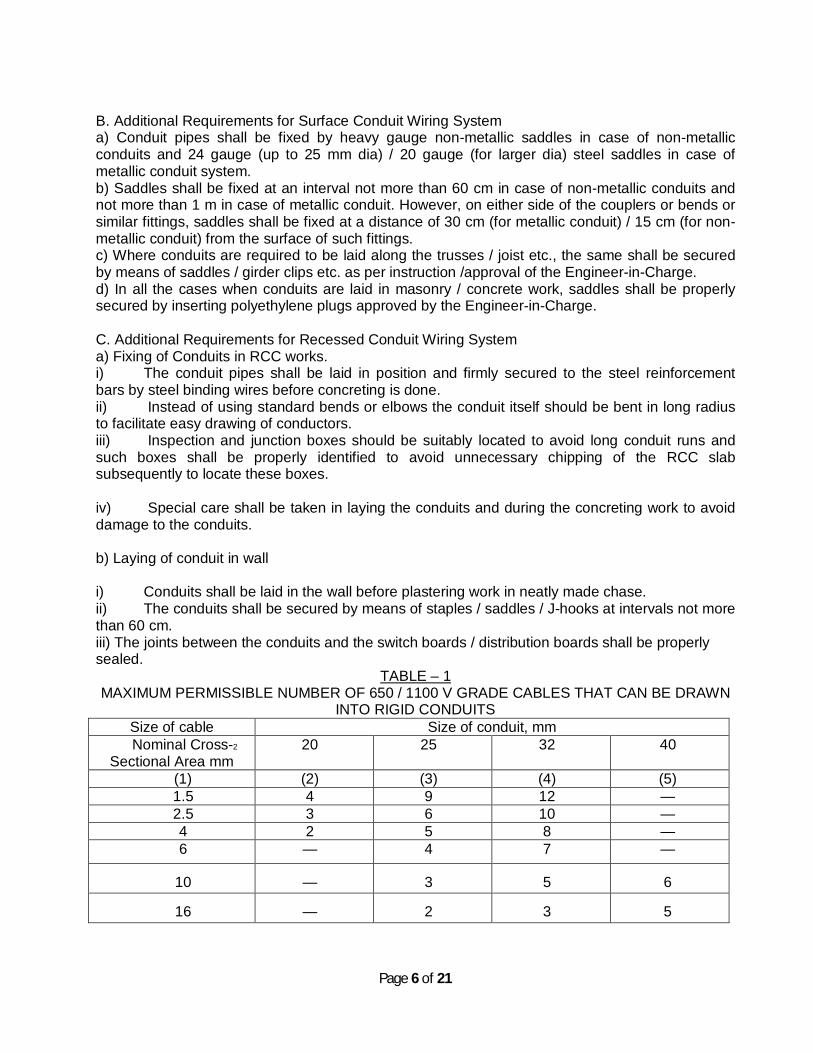
Page 6 of 21
B. Additional Requirements for Surface Conduit Wiring System a) Conduit pipes shall be fixed by heavy gauge non-metallic saddles in case of non-metallic conduits and 24 gauge (up to 25 mm dia) / 20 gauge (for larger dia) steel saddles in case of metallic conduit system. b) Saddles shall be fixed at an interval not more than 60 cm in case of non-metallic conduits and not more than 1 m in case of metallic conduit. However, on either side of the couplers or bends or similar fittings, saddles shall be fixed at a distance of 30 cm (for metallic conduit) / 15 cm (for non-metallic conduit) from the surface of such fittings. c) Where conduits are required to be laid along the trusses / joist etc., the same shall be secured by means of saddles / girder clips etc. as per instruction /approval of the Engineer-in-Charge. d) In all the cases when conduits are laid in masonry / concrete work, saddles shall be properly secured by inserting polyethylene plugs approved by the Engineer-in-Charge. C. Additional Requirements for Recessed Conduit Wiring System a) Fixing of Conduits in RCC works. i) The conduit pipes shall be laid in position and firmly secured to the steel reinforcement bars by steel binding wires before concreting is done. ii) Instead of using standard bends or elbows the conduit itself should be bent in long radius to facilitate easy drawing of conductors. iii) Inspection and junction boxes should be suitably located to avoid long conduit runs and such boxes shall be properly identified to avoid unnecessary chipping of the RCC slab subsequently to locate these boxes. iv) Special care shall be taken in laying the conduits and during the concreting work to avoid damage to the conduits. b) Laying of conduit in wall i) Conduits shall be laid in the wall before plastering work in neatly made chase. ii) The conduits shall be secured by means of staples / saddles / J-hooks at intervals not more than 60 cm. iii) The joints between the conduits and the switch boards / distribution boards shall be properly sealed.
TABLE – 1 MAXIMUM PERMISSIBLE NUMBER OF 650 / 1100 V GRADE CABLES THAT CAN BE DRAWN
INTO RIGID CONDUITS Size of cable Size of conduit, mm Nominal Cross-2
Sectional Area mm 20 25 32 40
(1) (2) (3) (4) (5) 1.5 4 9 12 — 2.5 3 6 10 — 4 2 5 8 — 6 — 4 7 —
10 — 3 5 6
16 — 2 3 5

Page 7 of 21
3.2 Casing Wiring System Casing wiring system may be adopted as specified by using metallic or PVC casingand capping. All specifications for casing wiring system shall be as per the ―GeneralSpecificationsǁ for Electrical Works (Part-I internal), 2005 of CPWD.
3.3 Earthing
a) Materials i) Earth electrodes shall be any of the following type as specified.
a) Pipe / rod earth electrode
b) Plate earth electrode
c) Strip electrode
Pipe electrode shall be of G.I. heavy class with minimum 38 mm dia and 2.5 m long as per details shown in the drawing. Rod electrodes may be of steel or copper of 2.5 m minimum length. Minimum dia shall be 16 mm in case of steel and 12.5 mm in case of copper. The electrodes shall have no joints. Plate electrodes may be of galvanised iron / steel or copper. In case of galvanised iron or steel thickness shall not be less than 6.30 mm, which in case of copper plate electrodes, thickness shall not be less than 3.15 mm. Minimum size of plate electrodes for both GI and copper shall be 60 cm x 60 cm. Strip electrodes shall not be smaller than 25 mm x 1.6 mm if of copper and 25 mm x 4 mm if of galvanized iron. If round conductors are used as earth electrodes,their cross sectional area shall not be smaller than 3.0sq. mm. if of copper and 6 sq.mm. if of G.I.
ii) The main earthing conductor (from earth electrode to the main switch board or earth bus) shall be of G.I. or copper as specified. The sizes shall also be as per specification. However, in no case the size of the main earthing conductor be less than
a) 5 mm dia (6 SWG) for G.I. or 4 mm dia (8 SWG) for copper wire. b) 25 mm x 4 mm in case of G.I. strip. c) 20 mm x 3 mm in case of copper strips.
iii) The earth continuity or loop earthing conductor shall be of copper, aluminium or G.I. as
specified. The minimum size of the earth continuity conductor shall be as follows : a) 2 mm dia (14 SWG) in case of bare copper (1.5 mm2 in case of
insulated) b) 2.24 mm dia (13 SWG) in case of bare aluminium 2.5 mm2 in case
ofinsulated) c) 2.5 mm dia (12 SWG) in case of G.I.
iv) Installation a)Electrodes shall be as far as practicable, be embedded belowpermanent
moisture level to a depth of at least 1.25 m. If rock is encountered, the depth of burial may be less than the specified value, subject to approval of the Engineer-in-Charge. In such case, theelectrodes may be buried inclined to the vertical with inclination not more than 30º from the vertical.
b) In case where more than one electrode has been specified, the distancebetween two electrodes shall preferably be not less than twice

Page 8 of 21
thelength of the electrode. c)Plate electrodes shall be buried such that its top edge is at a depth not
less than 1.5 m from the surface of the ground. d) Earth electrode normally shall not be located closer than 1.5 m from
anybuilding and should not be installed in proximity to a metal fence toavoid thepossibility of the fence becoming live due to voltage gradientof the electrodes.If the metal fence is unavoidable, it should be earthed.
e) The strip electrodes shall be buried in trenches or ditches not less than 0.5 m deep and the length of the buried conductor shall be sufficient to give the required earth resistance. It shall, however, be not less than 15m.
3.4 Installation of Fixtures / Fan i) Fixtures shall be firmly supported from the structures, support clamps, etc., may be bolted or welded to the existing steelwork or metal inserts. In case of concretestructures, where metal inserts are not available, fixtures will be fixed to orsupported from concrete surfaces with the help of anchor fastener. In such casesspecial care shall be taken to see that anchoring is firm. In case of concrete structures where metal inserts are not available, fixtures having smaller weights shall be supported by nylon sleeve / steel sleeveanchors inserting in neatly drilled holes or appropriate size as shown in thetypical drawing. Nylon or steel sleeve / rawl plugs should be inserted by making 1.5˝ deep, 0.25 dia, cylindrical hole using electric hand drill. In no case wooden plugs shall be allowed. This procedure shall be followed for fitting all types of electrical fittings, switchboard, conduits etc. on surface in wall / ceilings. ii) Fan clamps shall be of suitable design according to the nature of construction of the ceiling on which these clamps are to be filled. In all cases the fan clamps shall be fabricated from new metal of suitable sizes and they shall be as close fitting as possible. Fan clamps for reinforced concrete roof shall be buried with the casting and due care shall be taken that they shall serve the purpose. Fan clamps for woodbeams shall be of suitable flat iron fixed on two sides of the beam and according tothe size and section of the beam one or two mild steel bolts passing through the beam shall hold both flat iron together. Fan clamps for steel joints shall be fabricated from flat iron to fit rigidly to the bottom flange of the beam. Care shall be taken during fabrication that the metal does not crack while hammering to shape. In cases where false ceiling exists, the fans shall be firmly connected to the structure / ceiling and not to the false ceiling. 3.5 Lightning Protection i) Lightning protection shall be done in accordance with the tender specification,IS:2309-1989 and National Electrical Code. ii) The materials for the air-termination, down conductors etc. for the lightningprotective system shall be copper or G.I., as per specification. Recommendedshape and minimum sizes of the conductors for use above ground and beloware given below: Shape and minimum size of conductors for use above ground: Materials and shape Minimum size
Round copper wire : 6 mm dia Stranded copper wire : 50 mm2(or 7/3.0 mm dia) Copper strip : 20 x 3 mm Round galvanised iron : 8 mm dia Galvanised iron strip : 20 x 3 mm
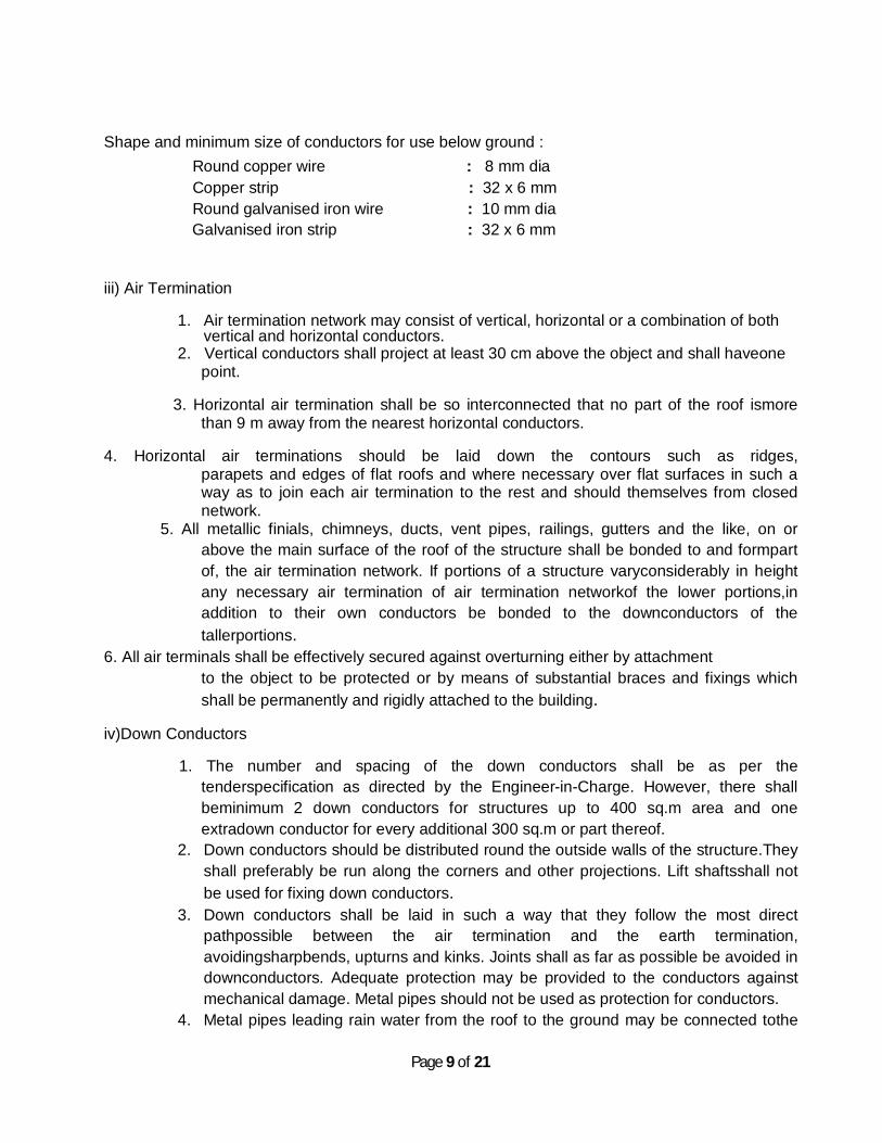
Page 9 of 21
Shape and minimum size of conductors for use below ground : Round copper wire : 8 mm dia Copper strip : 32 x 6 mm Round galvanised iron wire : 10 mm dia Galvanised iron strip : 32 x 6 mm iii) Air Termination
1. Air termination network may consist of vertical, horizontal or a combination of both vertical and horizontal conductors.
2. Vertical conductors shall project at least 30 cm above the object and shall haveone point.
3. Horizontal air termination shall be so interconnected that no part of the roof ismore
than 9 m away from the nearest horizontal conductors.
4. Horizontal air terminations should be laid down the contours such as ridges, parapets and edges of flat roofs and where necessary over flat surfaces in such a way as to join each air termination to the rest and should themselves from closed network.
5. All metallic finials, chimneys, ducts, vent pipes, railings, gutters and the like, on or above the main surface of the roof of the structure shall be bonded to and formpart of, the air termination network. If portions of a structure varyconsiderably in height any necessary air termination of air termination networkof the lower portions,in addition to their own conductors be bonded to the downconductors of the tallerportions.
6. All air terminals shall be effectively secured against overturning either by attachment to the object to be protected or by means of substantial braces and fixings which shall be permanently and rigidly attached to the building.
iv)Down Conductors 1. The number and spacing of the down conductors shall be as per the
tenderspecification as directed by the Engineer-in-Charge. However, there shall beminimum 2 down conductors for structures up to 400 sq.m area and one extradown conductor for every additional 300 sq.m or part thereof.
2. Down conductors should be distributed round the outside walls of the structure.They shall preferably be run along the corners and other projections. Lift shaftsshall not be used for fixing down conductors.
3. Down conductors shall be laid in such a way that they follow the most direct pathpossible between the air termination and the earth termination, avoidingsharpbends, upturns and kinks. Joints shall as far as possible be avoided in downconductors. Adequate protection may be provided to the conductors against mechanical damage. Metal pipes should not be used as protection for conductors.
4. Metal pipes leading rain water from the roof to the ground may be connected tothe

Page 10 of 21
down conductors. Such connections should have disconnecting joints fortesting purpose.
5. Any extended metal running vertically through the structure should be bondedto the lightning conductor at the top and the bottom unless the clearances are in accordance with IS:2309-1989.
6. Where the provision of suitable external routes for down conductors isimpracticable or inadvisable, as in buildings of cantilever construction, from the first floor upwards, down conductors may be used in an air space provided by a non-metallic, non- combustible internal duct. Any covered recess not smaller than 75 x 15 mm or anyvertical service duct running the full height of the building may be used for thispurpose, provided it does not contain an unarmoured or non-metal sheathed cable.
v) Joints and bonds
a) Joints The lightning protective system shall have as few joints in it as necessary. In thedown conductors below ground level these shall be mechanically and electricallyeffective and shall be so made as to exclude moisture completely. The joints maybe clamped, screwed, bolted, crimped, riverted or welded. With overlapping jointsthe length of the overlap should not be less than 20 mm for all types of conductors.Contact surfaces should first be cleaned and then inhibited from oxidation with asuitable non-corrosive compound. Joints of dissimilar metal should be suitablyprotected against bimetallic action and corrosion.In general, joints for strips shall be tinned, soldered, welded or brazed and at leastdouble-riverted. Clamped or bolted joints shall only be used on test points or onbonds to existing metal, but joints shall only be of the clamped or screwed type. b) Bonds External metal on or forming part of a structure may have to discharge the fulllightning current. Therefore, the bond to the lightning protective system shall havea cross-sectional area not less than that employed for the main conductors. On theother hand, internal metal is not so vulnerable and its associated bonds are atmost only likely to carry a portion of the total lightning current, apart from theirfunction of equalising potential. These latter bonds may, therefore, be smaller incross-sectional area than those used for the main conductors. All the bondsshould be suitably protected against corrosion. Bonds shall be as short aspossible.
c) Testing Points Each down conductor shall be provided with a testing point in a position convenient for testing but inaccessible for interference. No connection, other than one direct to an earth electrode, shall be made below a testing point. Testing points shall be phosphorbronze, gunmetal, copper or any other suitable material. d) Earth Terminations
1. Each down conductor shall have an independent earth termination. It should be
capable of isolation for testing purposes. Suitable location for the earth termination

Page 11 of 21
shall be selected after testing and assessing the specific resistivity of the soil and with due regard to reliability of the sub-soil water to ensure minimum soil moistness.
2. Water pipe system should not be bonded to the earth termination system.However, if adequate clearance between the two cannot be obtained, they may be effectivelybonded and the bonds should be capable of isolation and testing. The gas pipes, however, should in no case be bonded to the earth termination system.
3. It is recommended that all earth terminations should be interconnected. Common
earthing besides equalising the voltage at various earth terminationsalso minimises any risk to it of mechanical damage.
e) Earth Electrodes Earth electrodes shall be constructed and installed in accordance with section 3.3.
f) Fasteners Conductors shall be securely attached to the building or other object to be protected by fasteners which shall be substantial in construction, not subject to breakage and shall be made of galvanised steel or other suitable material. If fasteners are made of steel, they should be galvanised to protect them against corrosion. If they are made of any other material suitable precautions should be taken to avoid corrosion. Some samples of fasteners are shown in IS:2309-1969.
g) Earth Resistance
Each earth termination should have a resistance in ohms to earth not exceedingnumerically the product of 10 and the number of earth terminations to beprovided. The whole of the lightning protective system should have a combinedresistance to earth not exceeding 10 ohms before any bonding has been effectedto metal in or on the structure or to surface below ground.
3.6Testing of Wiring Installation After completion of wiring a general inspection is carried out by the Engineer-in-Charge or his representative to verify that the provisions of the specification and Indian Electricity Rules, 1956 have been complied with. After inspection, the following tests shall be carried out before an installation or an addition to theexisting installation is put into service: a) The insulation resistance shall be measured by applying between earth and thewhole system
of conductor or any section thereof with all fuses in place and allswitches closed and except in earthed concentric wiring, all lamps in position orboth poles of installation otherwise electrically connected together, a DCvoltage of not less than twice the working voltage, provided that it does notexceed 500 volts for medium voltage circuits. Where the supply is derived from thee-wire (AC or DC) or a polyphase system the neutral pole of which isconnected to earth either direct or through added resistance, the workingvoltage shall be deemed to be that which is maintained between the outer orphase conductor and the neutral.
b) The insulation resistance in mega-ohms of an installation measured as in (a) shallbe not less
Page 12 of 21
than 50 divided by the number of points on the circuit, provided thatthe whole installation need not be required to have an insulation resistance greater than 1 M ohm.
c) Control rheostats, heating and power appliances and electric signs, may, ifdesired,be disconnected from the circuit during the test, but in that event theinsulation resistance between the case or framework, and all live parts of eachrheostat, appliance and sign shall be not less than that specified in the relevant Indian Standard specification or where there is no such specification shall benot less than 0.5 M ohm.
d) The insulation resistance shall also be measured between all conductors connected to one pole or phase conductor of the supply and all the conductors connected to the middle wire to the neutral on to the other pole of phase conductorsof the supply. Such a test shall be made after removing all metallic connectionsbetween the two poles of the installation and in these circumstances the insulationresistance between conductors of the installation shall be not less than that specified in (b).
e) On completion of an electrical installation (or an extension to an installation) a certificate shall be furnished by the Contractor, countersigned by the certified supervisor under whose direct supervision the installation was carried out. This certificate shall be in a prescribed form as required by the local electric supply authority. In addition to this a completion certificate, as enclosed under Appendix – I.
Earthing For checking the efficiency of earthing the following tests are recommended.
a) The earth resistance of each electrode is measured. b) The earth resistance of earthing grid is measured c)All electrodes are connected to the grid and the earth resistance of the entire
earthing system is measured. These tests shall preferably be done during the summer months.
4.0 Cable Laying 4.1 Route i) Before the cable laying work is undertaken, the route layout of the cable shall be
submitted to the Engineer-in-Charge and the work shall be undertaken only after approval of the route layout.
ii) a) Whenever cables of different voltages are laid following points shall be noted while laying along well demarcated or established roads, the LV / MV cables shall be laid further from the kerb line than HV cables. b)Cables of different voltages and also power and control cables shall be kept indifferent trenches with adequate separation. Where available space is restricted such that this requirement cannot be met, LV / MV cables shall be laid above HV cables.
c) Where cables cross one another, the cable of higher voltage shall be laid at a lower level than the cable of lower voltage.
iii) Proximity to communication cables Power and communication cables shall as far as possible cross each other at

Page 13 of 21
rightangels. The horizontal and vertical clearance between them shall not be less than 60cm.
4.2Methods of Laying The cables shall be laid direct in ground, pipe, closed or open ducts, cable trays oron surface of wall etc. The method(s) of laying required shall be specified in thetender / schedule of work.
4.3Laying direct in ground i) This method shall be adopted where specified in the schedule of works.Normally this method shall be adopted when the cable route is through openground, along roads, lanes, etc. and where no frequent excavations are likelyto be encountered and where re-excavation is easily possible without affectingother services. ii) Trenching a) Width and depth of the trench shall be as shown in the drawing. When more than one tier of
cables is unavoidable and vertical formation of laying is adopted, the depth of the trench shall be increased by 30 cm for each additional tier to be formed.
b)The trenches shall be excavated in reasonably straight lines. Wherever there is a change in the direction, a suitable curvature shall be adoptedcomplying with the minimum bending radius specified in Table – 11. Wheregradients and changes in depth are unavoidable, these shall be gradual.The bottom of the trench shall be level and free from stones, brick bats etc.
TABLE – 2 MINIMUM BENDING RADIUS – PAPER INSULATED CABLES AND XLPE
CABLES
System voltage Minimum bending radius Single core Multi core
Unarmoured Armoured 11 KV 20 D 15 D 12 D 22 KV 25 D 20 D 15 D 33 KV 30 D 25 D 20 D
D is the overall diameter of the cable. The excavation should be done by suitable means – manual or mechanical. The excavated soil
shall be stacked firmly by the side of the trench such that it may notfall backinto the trench. c)Adequate precautions should be taken not to damage any existing cable(s),
pipes or any other such installations in the route during excavation. Wherever bricks, tiles or protective covers or bare cables are encountered, further excavation shall not be carried out without the approval of the Engineer-in-Charge.
Existing property, if any, exposed during trenching shall be temporarily supported adequately as directed by the Engineer-in-Charge. The trenching in such cases shall be done in short lengths, necessary pipes laid for passing cables therein, if required.

Page 14 of 21
If there is any danger of a trench collapsing or endangering adjacent structures, the sides should be well shored up with sheeting as the excavation proceeds. Where necessary, these may even be left in place when backfilling the trench. Excavation through lawns shall be done in consultation with the department concerned.
iii) Laying of Cable in Trench
a) Sand cushioning The excavated trench shall be provided with a layer of clean, dry sand cushion of not less than 8 cm in depth, before laying the cables therein. However, sand cushioning may not be provided for MV cables, where there is no possibility of any mechanical damage to the cables due to heavy or shock loading on the soil above if so specified in the tender document and as per approval of the Engineer-in-Charge. Sand cushioning shall however be invariably provided in the case of HV cables.
b)The cable drum shall be properly mounted on jacks, or on a cable wheel atsuitable location, making sure that the spindle, jack etc. are strong enough tocarry the weight of the drum without failure and that the spindle is horizontal inthe bearings so as to prevent the drum creeping to one side while rotating. c) The cable shall be pulled over in rollers in the trench steadily and uniformly without jerks and strain. The entire cable length shall be far as possible laid off in one stretch. PVC / XLPE cables less than 120 sq.mm size may be removed by ―Flakingǁ i.e. by making one long loop in the reverse direction.
Note: For short runs and sizes up to 50 sq.mm of MV cables, any other suitable method of direct handling and laying can be adopted without strain or excess bending of the cables.
d) After the cable has been so uncoiled, it shall be lifted slightly over therollersbeginning from one end by helpers standing about 10 m apart and drawnstraight. The cable shall then be lifted off the rollers and laid in a reasonablystraight line.
e) Testing before covering
The cables shall be tested in presence of the Engineer-in-Charge for continuity of cores and insulation resistance and the cable length shall be measured, beforeclosing the trench. f)Sand covering Cables laid in trenches in a single tier formation shall have a covering of dry sand of not less than 17 cm above the base cushion of sand before the protective cover is laid. In the case of vertical multi-tier formation, after the first cable has been laid, a sand cushion of 30 cm shall be provided over the base cushion before the second tier is laid. If additional tiers are formed, each of the subsequent tiers alsoshall have asand cushion of 30 cm as stated above. Cables in the top most tiershall have afinal sand covering not

Page 15 of 21
less than 17 cm before the protective cover is laid. Sand covering as stated above need not be provided for MV cables where a decision is taken by the Engineer-in-Charge as per sub-clause (iii-a) above, but the inter tier spacing should be maintained with soft soil instead of sand between tiers and for covering. Sand cushioning shall however be invariably provided in the case of HV cables. g) Extra loop cable At the time of original installation, approximately 3 m of surplus cable shall be left on each terminal end of the cable and on each side of the underground joints. Thesurplus cable shall be left in the form of a loop. Where there are long runs of cablessuch loose cable may be left at suitable intervals as specified by the Engineer-in-Charge.Where it may not be practically possible to provide separation between cables when forming loops of a number of cables as in the case of cable emanating from a substation, measurement shall be made only to the extent of actual volume of excavation, sand filling etc and paid for accordingly. h)Mechanical protection over the covering Mechanical protection to cables shall be laid over the covering to provide warning to future excavators of the present of the cable and also to protect the cable against accidental mechanical damage by pick-axe blows etc. as follows: i) Unless otherwise specified, the cables shall be protected by second class brick ofnominal size 22 cm x 11.4 cm x 7 cm or locally available size, placed on top ofthe sand (or, soil as the case may be). The bricks shall be placed breadth-wise forthe fulllength of the cable. Where more than one cable is to be laid in the sametrench, this protective covering shall cove all the cables and projects at least 5 cmover the sides of the end cables. ii)Where bricks are not easily available, or are comparatively costly, there is noobjection to use locally available material such as tiles or slates or stone /cement concrete slabs. Where such an alternative is acceptable, the same shall beclearly specified in the tender specifications.
iv) Backfilling
a)The trenches shall be then backfilled with excavated earth, free from stones or other shall edged debris and shall be rammed and watered, if necessary insuccessive layers not exceeding 30 cm depth. b)Unless otherwise specified, a crown of earth not less than 50 mm and notexceeding 100 mm in the centre and tapering towards the sides of the trenchshall be left to allow for subsidence. The crown of the earth,however, should not exceed 10 cms. so as not to be a hazard to vehicular traffic. c)The temporary restatements of roadways should be inspected at regularintervals, particularly during wet weather and settlements should be madegood by further filling as may be required. d) After the subsidence has ceased, trenches cut through roadways or other paved areas shall be restored to the same density and materials as the surrounding area and repaved in accordance with the relevant building specifications to the satisfaction of the Engineer-in-Charge.

Page 16 of 21
e) Where road berms of lawns have been cut out of necessity, or kerb stonesdisplaced, the same shall be repaired and made good, except for turfing /asphalting, to the satisfaction of the Engineer-in-Charge and all the surplus earthor rock shall be removed to places as specified. v)Laying of single core cables
a) Three single core cables forming one three phase circuit shall normally beheld in close trefoil formation and shall be bound together at intervals of approximately 1 m. b) The relative position of the three cables shall be changed at each joint at thetime of original installation, complete transposition being effected inevery three consecutive cable lengths.
vi) Route markers
a) Location Route markers shall be provided along with the runs of cable at locations approvedby the Engineer-in-Charge and generally at intervals notexceeding 100m. Markersshall also be provided to identify change in the direction of the cable route and locations of underground joints. b) Plate type marker Route markers shall be made out of 100 mm x 5 mm G.I. / aluminium plate welded /bolted on 35 mm x 35 mm x 6 mm angel iron, 60 cm long. Suchplate markers shall be mounted parallel to and at about 0.5 m away from the edge of the trench.
c) CC marker Alternatively, cement concrete 1:2:4 (1 cement : 2 coarse sand : 4 gradedstoneaggregate of 20 mm in size) as shown in figure 2 shall be laid flat and centered overthe cable. The concrete markers, unless otherwise instructed by the Engineer-in-Charge, shall project over the surrounding surface so as to make the cable route easily identifiable. d) Inscription The words IITG-MV / HV CABLE as the case may be shall be inscribed on the marker. 4.4 Laying in Pipes / Closed Ducts i) In locations such as road crossing, entry in to buildings, paved areas etc.,cables shall be laid
in pipes or closed ducts. Stone ware pipes, GI, CI or spunreinforced concrete pipes shall be used for cables as specified in the scheduleof works.
ii) Following guide of the pipe fill shall be used for sizing the pipe size : a) 1 cable in pipe : 53% full b) 2 cables in pipe : 31% full c) 3 or more cables : 43% full d) Multiple cables : 40% full iii) Where cables pass through foundation walls or other underground structures, the necessary ducts or openings will be provided in advance for the same. However, should it become necessary to cut holes in existing foundations orstructures, the electrical contractor shall determine their location and obtainapproval of the Engineer-in-Charge before cutting is done. iv) At road crossing and other places where cables enter pipe sleeves adequatebed of sand shall be given so that the cables do not slack and get damaged bypipe ends. v) At road crossings, the top surface of pipes shall be at a minimum depth of 1mfrom the

Page 17 of 21
pavement level. When pipes are laid cutting existing road, care shall be taken so that the soil filled up after laying the pipes is rammed well in layers with watering as required to ensure proper compaction. A crown of earth notexceeding 10 cm should be left at the top. After the subsidence has ceased, the top of the filled up trenches in road waysor other paved areas shall be restored to the same density and material as thesurrounding area in accordance with the direction of the Engineer-in-Charge(Civil) up to his satisfaction. vi) All G.I. pipes shall be laid as per layout drawings and site requirements. Beforefabrication of various profiles of pipe by hydraulically operated bendingmachine(which is to be arranged by the Contractor), all the burrs from the pipes shall beremoved. G.I. pipes with bends shall be buried in soil / concretein such a waythat the bends shall be totally concealed. For G.I. pipes buried in soil, bitumencoating shall be applied on the buried lengths. Installation of G.I. pipes shall beundertaken well before paving is completed and necessary coordination withpaving agency shall be the responsibility of Electrical Contractor. The openends of pipes shall be suitably plugged with G.I. plugs after they are laid in finalposition. G.I. plugs shall be supplied by the Contractor at no extra cost.
4.5Laying in Open Ducts
a) Open ducts with suitable removable covers (RCC slabs or chequered plates)are generally provided in substations, switch rooms, plant rooms, workshopsetc. for taking the cables. The cable ducts should be of suitable dimensions forthe number of cables involved. b) Laying of cables with different voltage ratings in the same duct shall be avoided.Where it is inescapable to take HV & MV cables same trench, they shall be laidwith a barrier between them or alternatively, one of the two (HV / MV) cablesmay be taken through pipe(s).Splices or joints of any type shall not be permitted inside the ducts. c) The cables shall be laid directly in the duct such that unnecessary crossing ofcables is avoided. d) Where specified, cables may be fixed with clamps on the walls of the duct ortaken in hooks / brackets / cable trays through in ducts. e) Where specified, ducts may be filled with dry sand after the cables are laid andcovered as above, or finished with cement plaster, specially in high voltageapplications.
4.6Laying on Surface The method may be adopted in places like switch rooms, workshops, tunnels, rising(distribution) mains in buildings etc. This may be necessitated in the works of additions and / or alternations to the existing installation, where other methods of laying may not be feasible. Cables may be laid in surface by any of the following methods as specified:
a) Directly clamped by saddles or clamps b) Supported on cradles c) Laid on troughs / trays, duly clamped.
4.7Laying on Cable Tray This method may be adopted in places like indoor substations, air-conditioning plant rooms, generator rooms etc. or where long horizontal runs of cables are

Page 18 of 21
required within the building and where it is not convenient to carry the cable in open ducts.This method is preferred where heavy sized cables or a number of cables are required to be laid. The cable trays may be either of perforated sheet type or ladder type as specified. 4.8Jointing i) Location a) Before laying a cable, proper locations for the proposed cable joints, if any,shall be decided, so that when the cable is actually laid, the joints are made inthe most suitable places. As far as possible, water logged locations, carriageways, pavements, proximity to telephone cables, gas or water mains,inaccessible places, ducts, pipes, racks etc. shall be avoided for locating thecable joints. b) Joints shall be staggered by 2 m to 3 m when joints are to be done for two ormore cables laid together in the same trench. ii) Joint pits a) Joints pits shall be of sufficient dimensions as to allow easy and comfortableworking. The sides of the pit shall be well protected from loose earth falling into it. It shall also be covered by a tarpaulin to prevent dust and other foreignmatter being blown on the exposed joints and jointing materials. b) Sufficient ventilation shall be provided during jointing operation in order todisperse fumes given out by fluxing. iii) Safety precaution a) A caution board indicating ―CAUTION – CABLE JOINTING WORK INPROGRESSǁ shall be displayed to warn the public and traffic wherenecessary. b) Before jointing is commenced, all safety precautions like isolation, discharging, earthing, display of caution board on the controlling switchgearetc. shall be taken to ensure that the cable wound not be inadvertentlycharged form live supply. Metallic armour and external metallic bondbe connected to earth. Where ―Permit to Workǁ system is in vogue, safetyprocedures prescribed shall be complied with.
iv) Jointer Jointing work shall be carried out by a licensed / experienced (where there isno licensing system for jointers) cable jointer. 4.9 Testing i) Testing before laying All cables, before laying, shall be tested with a 500 V megger for cables of 1.1 KVgrade, or with a 2500 / 5000 V megger for cables of higher voltage. The cablecores shall be tested for continuity, absence of cross phasing, insulationresistancefrom conductors to earth / armour and between conductors. ii)Testing before backfilling
All cables shall be subjected to the above mentioned tests, before covering the cables by protective covers and backfilling and also before taking up any jointingoperation.

Page 19 of 21
Working Volts in KV
AC 15 minutes test DC 15 minutes test
Between conductors
Conductor to earth
Between conductors
Conductor to earth
Up to 1.1 2.0 2.0 3.0 3.0 3.3 6.0 3.5 9.0 5.0 6.6 12.0 7.0 18.0 10.5 11 20.0 11.5 30.0 17.5 22 40.0 23.0 60.0 35.0 33 - - - 60.0
iii) Testing after laying After laying and jointing, the cable shall be subjected to a 15 minutes pressure test.The test pressure shall be as given in Table – III. DC pressure testing may normally be preferred compared to AC pressure testing. TABLE – 3 TEST PRESSURE IN KV
In the absence of facilities for pressure testing as above, it is sufficient to test for one minute with 1,000 V megger for cables of 1.1 KV grade and with 2500 /5000 V megger for cables of higher voltages. 4.10 Measurement All measurement will be made as per guidelines laid under the latest edition of theGeneral Specifications for Electrical works (Part – I and II) of CPWD. All the worksin progress will be jointly measured by the representatives of the Engineer-in-Charge of the Owner and EPI and the Sub-contractor shall remain bound to render all assistance during such recording of the measurements. The measurements such recorded shall be binding on the Sub-contractor. He shall have no claim other than what has been jointly recorded or certified by the Owner. 4.10 Specific Technical Requirements:
a) All wiring for light and power circuits shall be in PVC conduits recessed or exposed in wall /ceiling as instructed by the Engineer-in-charge.
b) All wires for point wiring and the single core wires specified for sub main and circuit wirings shall be 1.1 KV grade PVC insulated FR copper multi-strand wires of approved brand. The underground cables indicated in the drawings shall however, be PVC insulated and sheathed armoured aluminium underground cables of approved brands.
c) All 6A receptacles shall be flush type and shall have 5 pins with 1 pin for earth connection and 2 pins each for phase and neutral connections. 16A receptaclesshall have 6 pins (suitable for connecting both 6A and 16A plug tops) with 2 pinseach for phase, neutral and earth connections.
d) Samples of all the materials to be used in the work shall be submitted to the Superintending Engineer (Elect.), IITG for approval. No material other than those approved by the IITG shall be used in any of the works. In case of any materials other than those approved by the SE (Elect.) is detected,the same shall be replaced by the Tenderer with the approved quality, free of cost,failing which, the owner shall have right to withhold all pending bills due to theContractor, until the

Page 20 of 21
rectification / replacement work is completed. e) All materials, equipments and accessories shall be of makes listed as enclosed. Makes of
any item(s) not specified under the list, but required in the work shall be approved by the Engineer-in-Charge prior to use in the works.
f) After partitions & placing work stations the position of the switch boards have to be changed as well as new wirings will be needed for the work stations.
g) Separate switch boards will be fixed for each incubation/partitions hence additional switch boards are required.
h) The lighting arrangements will have to be changed according to the new setup and more luminaries will be required.
i) The existing LAN cablings does not match the new proposed furniture plan, so entire LAN work proposed to be done in fresh, routing above the ceiling and through specially designed Tray to be fixed all along the partitions and brick walls.
j) In addition to existing CCTV cameras of common space of building, new CCTV cameras will be installed for STPI’s own administration covering STPI’s space only.
LIST OF APPROVED MAKES OF MATERIALS:
Sl. No.
Name of Materials Manufactures / Brand names
1. Conduits pipes & accessories – MS PVC
BEC / AKG (ISI marked) BERLIA / AKG
2. Bushes Rubber / PVC of superior quality. 3. Wire (Copper conductor) FR copper wire (FINOLEX / HAVELLS / RR KABEL
/ANCHOR)/BERLIA/NICCO/V-GUARD/Gloster 4. Cable (underground)
GLOSTER / CCI / INCAB / INDUSTRIAL CABLES /RPG / UNIVERSAL / NICCO / HAVELLS / POLYCAB/ CRYSTAL / FINOLEX/KEI
5. Cover plate
Hylum sheet 3 mm thick of colour & design as approved
6. Cover plate fan box
Formica of approved shade 2 mm thick
7. Switch & Socket - Flash Piano type - ANCHOR / KOLORS / GOLDMEDAL/HPL/HAVELLS
(ISI) or equiv. Modular type - MK / CRABTREE / LEGRAND / SCHNEIDER
/PHILIPS 8. Switch fuse unit (HRC Type) (re-
wirable type) ENGLISH ELECTRIC/L&T/ SIEMENS/CONTROL&SWITCHGEAR
9. a) Fuse bases for HRC fuse forfeeder pillar b) HRC fuses
SIEMENS / L&T / STANDARD E.E. / L&T / SIEMENS
10. MCB LEGRAND/SIEMENS/ SCHNEIDER / L&T / ABB /HAVELLS / HAGER

Page 21 of 21
11. Distribution Board MCB type LEGRAND/SIEMENS/ SCHNEIDER / L&T / ABB /HAVELLS / HAGER
12. Telephone cables DELTON / FINOLEX / POLYCAB 13. Computer cable: Cat - 6 AMP / D-LINK / LEGRAND / RR KABEL
/KRONE/DIGILINK 14. Computer jack : RJ-45 AMP/D-LINK/LEGRAND/SYSTIMAX
/KRONE/DIGILINK 15. Screws Good quality brass screws 16. Ceiling Rose ANCHOR / MK / GOLDMEDAL / KOLORS 17. ELCB / RCCB LEGRAND / SIEMENS / L&T / ABB / HAVELLS
/SCHNEIDER / HAGER 18. MCCB GE/L&T/SCHNEIDER/CONTROL&SWITCHGEAR/C
ROMPTONGREAVES/ABB/C&S/HAVELLS/LEGRAND / HAGER
19. Air Circuit Breaker L&T/SIEMENS/SCHNEIDER/ CROMPTONGREAVES/ABB/CONTROL& SWITCHGEAR.
20. Industrial type Metal clad sockets &plugs
LEGRAND/SIEMENS/ SCHNEIDER / L&T /HAVELLS / ABB.
21. Meter, Metering, Equipment &C.T.s A) AUTOMATIC ELECTRIC B) CONZERV C) RISHAV D) MECO E) HPL
22. Electronic Energy Meter HPL / CONZERV / L&T / RISHAV 23. Exhaust Fan ALSTOM / ORIENT / CROMPTON / HAVELS 24. Ceiling Fan ORIENT/CROMPTON/BAJAJ/HAVELS / BERLIA 25. Electronic Step Fan Regulator ANCHOR / KOLORS / MK or equiv. 26. Lugs DOWELLSǁ crimping type 27. MDBs / BDBs / SDBs CPRI approved vendors, having facilities for
powdercoated finish and antirust treatment by seven/ eighttank process (vendor detail shall be submitted forapproval)
28. APFC Panel SCHNEIDER/L&T or equivalent subject to approval. 29. Bus-bar trunking system Control & Switchgear or equiv. Subject to approval 30. Light fittings Makes & catalogue reference shown in the BOQ
orequivalent from the brands–Philips/Crompton/Bajaj/Wipro/Havells – subject to approval.

List of Drawings
NIT No. &Date: NERO/MMD/STPI-Agartala/253 Dated: 05.07.2017
Tender for Renovation and Interior work in IT complex cum Software Technology Park building located at Indranagar, Agartala for creation of state of the art STPI facilities”
Sl. No Title of Drawing
Drawing No
1 Third Floor Plan STPI/AGR/FL PLAN/01
2 Forth Floor Plan STPI/AGR/FL PLAN/02
3 3rd floor furniture details Director’s Table STPI/AGR/FUR/01
4 3rd floor furniture details Asst. Director’s Table STPI/AGR/FUR/02
5 3rd floor furniture details Reception Table STPI/AGR/FUR/03
6 3rd floor furniture details Meeting Table STPI/AGR/FUR/04
7 3rd floor furniture details Dry Pantry STPI/AGR/FUR/05
8 3rd floor furniture details Conference room cabinet STPI/AGR/FUR/06
9 3rd floor furniture details Cabinet in corridor STPI/AGR/FUR/07
10 3rd floor furniture details STPI Cabinet STPI/AGR/FUR/08-1
11 3rd floor furniture details STPI Cabinet STPI/AGR/FUR/08-2
12 3rd floor furniture details STPI Cabinet STPI/AGR/FUR/08-3
13 3rd floor furniture details STPI Cabinet STPI/AGR/FUR/08-4
14 4th floor furniture details STPI Seminar Hall Table STPI/AGR/FUR/09
15 4th floor furniture details Dry Pantry STPI/AGR/FUR/10
16 4th floor furniture details Meeting Table STPI/AGR/FUR/11
17 Dry Wall Partition details at floor Level STPI/AGR/FUR/12
18 Dry Wall Partition details at ceiling Level STPI/AGR/FUR/13
19 3rd Floor Plan STPI/AGR/FL PLAN/01
20 4th Floor Plan STPI/AGR/FL PLAN/02

Note: The drawings enclosed are as received from the Consultant for general guidance only. The works shall beexecuted as per the detail drawings to be finalized during execution and as perinstructions of the Owner.

SYSTEM ROOM
EMERGENCYEXIT
WAITINGSPACE
3M WIDE LOBBY
RECEPTION
DIRECTOR'SROOM
DIRECTOR'S OFFICE
TO STPI'SOFFICE
7' WIDE CORRIDOR
PRIVATEAREA
FOYERCHANGING/RM
PANTRYDRY
CONFERENCE HALL
TO SYSTEM RM
STORE
UP
ENTRANCELOBBY
UNIT-233 SEAT
UNIT-330 SEAT UNIT-4
23 SEAT
7.8X8.0 MAX
2.4X1.9
2.4X3.3
EMERGENCYEXIT
ELECTRICALRM
AHU
PANKAJ PHUKAN AND ASSOCIATESANIL NILOY, 2ND FLOOR.
DR. B.K. KAKATI ROAD,
ULUBARI, GUWAHATI-781007
PHONE: 0361-2466-47/ MOBILE : +91 9435102280
EMAIL :[email protected], [email protected]
NOTE : UNAUTHORISED DUPLICATION IN PART OR IN FULL WITHOUT PERMISSION FROM ARCHITECT IS A LEGAL OFFENCE
FURNITURE LAYOUT PLAN AT 3RD FLOOR LEVEL.
UNIT-120 SEAT
UNIT-240 SEAT
7.6X5.3
RECORD RM2.8X4.5
MEETING RM3.6X4.5
2212 2212
1200
10620
2555
8289
11025
18
60
1410
FH Cabinet FH Cabinet
FH Cabinet
FH Cabinet
FH Cabinet
FH C
abin
et
FH C
abin
et
FH Cabinet
600
11
60
5100
13
40
15
00
1500
12
00
3000
15
00

SYSTEM ROOM
EMERGENCYEXIT
LIBRARY
REFRESMENT ZONE
DRY PANTRY
WASH BASIN
WAITINGSPACE
PASSAGE
3M WIDE LOBBY
TO SYSTEM RM
UNIT-120 SEAT
UNIT-240 SEAT
UNIT-330 SEAT
UNIT-423 SEAT
ENTRANCELOBBY
MEETING RM
7.6X5.9
5.4X4.5
7.8X8.0M
ELECTRICALRM
AHU
PANKAJ PHUKAN AND ASSOCIATESANIL NILOY, 2ND FLOOR.
DR. B.K. KAKATI ROAD,
ULUBARI, GUWAHATI-781007
PHONE: 0361-2466-47/ MOBILE : +91 9435102280
EMAIL :[email protected], [email protected]
NOTE : UNAUTHORISED DUPLICATION IN PART OR IN FULL WITHOUT PERMISSION FROM ARCHITECT IS A LEGAL OFFENCE
FURNITURE LAYOUT PLAN AT 4TH FLOOR LEVEL.
LOBBY LOBBY
DICE
SCREEN
CLASS ROOM TYPESEMINAR HALL7.7X12.6M
3860
2273
1800
3000

XX'
Y'
Y
A
B
C
ELEVATION A
ELEVATION B
SECTION XX'
SECTION YY'
ELEVATION C
512
22731673
2012
1100
100
1500
512
600
3000
660
600 1750 600
3000
5050
660
100
150
950 1600 512
280
280
1200 375 375 375 375 512
700
379 379 379 379 379 379
590
60
2273
650
200
200
200
5050
60
270
300
600 1750 600
3000
760
150
DETAIL D
7075
30
75
30
75
30
75
30
7514
2
DETAIL AT D
3RD FLOOR FURNITURE DETAILS - DIRECTOR'S TABLE
ENGINEERING PROJECTS (INDIA) LTD
Client Project Management consultant Architect:PANKAJ PHUKAN AND ASSOCIATESANIL NILOY, 2ND FLOORDR. B. K. KAKATI ROAD, ULUBARI, GUWAHATI-781007PH: 0361-2466-47/+919435102260EMAIL: [email protected], [email protected] technology park of
India
Project name:
Drawing Title:
INTERIOR WORK FOR SOFTWARE TECHNOLOGY PARK ATAGARTALA, TRIPURA
Date: 31-05-2017 Drawing No: STPI/AGR/FUR/01
TENDER DRAWINGS
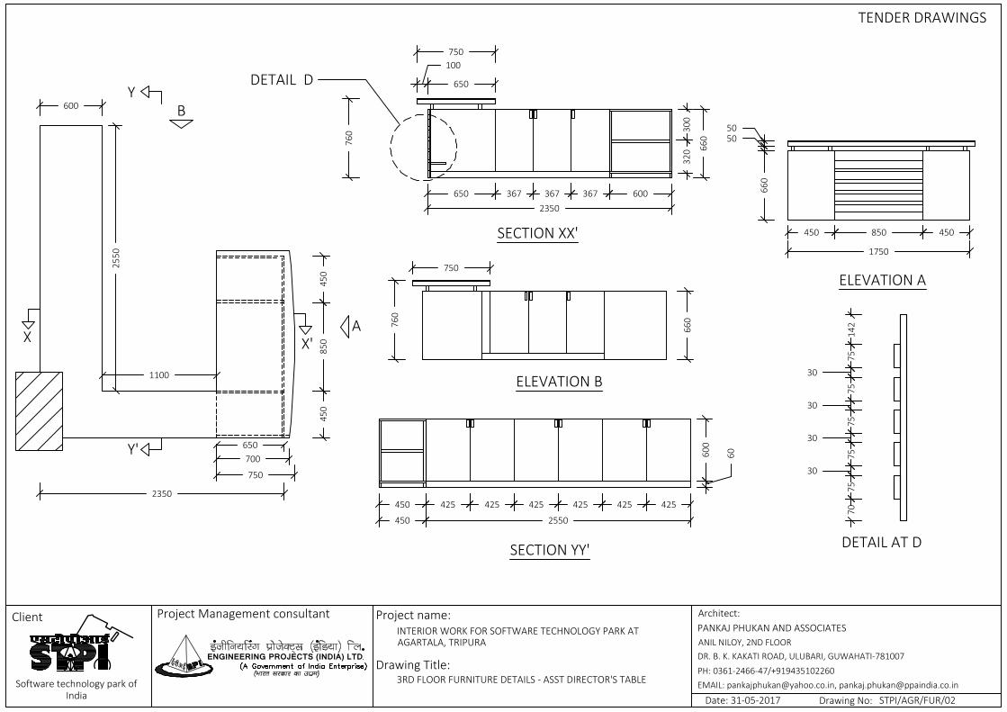
660
5050
450 850 450
1750
650
750
700
450
850
450
100
650
750
300
320 66
0
650 367 367 367 6002350
750
760
660
760
450 425 425 425 425 425 425
60600
450 2550
A
ELEVATION A
B
ELEVATION B
XX'
SECTION XX'
Y'
Y
SECTION YY'
2550
1100
600
2350
7075
30
75
30
75
30
75
30
7514
2
DETAIL AT D
DETAIL D
3RD FLOOR FURNITURE DETAILS - ASST DIRECTOR'S TABLE
ENGINEERING PROJECTS (INDIA) LTD
Client Project Management consultant Architect:PANKAJ PHUKAN AND ASSOCIATESANIL NILOY, 2ND FLOORDR. B. K. KAKATI ROAD, ULUBARI, GUWAHATI-781007PH: 0361-2466-47/+919435102260EMAIL: [email protected], [email protected] technology park of
India
Project name:
Drawing Title:
INTERIOR WORK FOR SOFTWARE TECHNOLOGY PARK ATAGARTALA, TRIPURA
Date: 31-05-2017 Drawing No: STPI/AGR/FUR/02
TENDER DRAWINGS

600
1239
220
740 742
450
1239
150
850
600
400
1000
100
1299 302 298
1966
A
150
500
350
223
450 926
0
ELEVATION A
590
60
413 413 413 600100
400
450
150 10
00
413 413 413 600100
250
200
800 10
00
120
ELEVATION B SECTION YY'
SECTION XX'
B
Y'
Y
XX'
400
100
3RD FLOOR FURNITURE DETAILS - RECEPTION TABLE
STPI/AGR/FUR/03
ENGINEERING PROJECTS (INDIA) LTD
Client Project Management consultant Architect:PANKAJ PHUKAN AND ASSOCIATESANIL NILOY, 2ND FLOORDR. B. K. KAKATI ROAD, ULUBARI, GUWAHATI-781007PH: 0361-2466-47/+919435102260EMAIL: [email protected], [email protected] technology park of
India
Project name:
Drawing Title:
INTERIOR WORK FOR SOFTWARE TECHNOLOGY PARK ATAGARTALA, TRIPURA
Date: 31-05-2017 Drawing No:
TENDER DRAWINGS

900
2400
130
580
50
200
1971
2292400
2000
150560
50
150560
50
500
900
200
500
200
200200
760
A
Y'
Y
XX'
ELEVATION A
SECTION YY'
SECTION XX'
PLAN
3RD FLOOR FURNITURE DETAILS - MEETING ROOM TABLE
ENGINEERING PROJECTS (INDIA) LTD
Client Project Management consultant Architect:PANKAJ PHUKAN AND ASSOCIATESANIL NILOY, 2ND FLOORDR. B. K. KAKATI ROAD, ULUBARI, GUWAHATI-781007PH: 0361-2466-47/+919435102260EMAIL: [email protected], [email protected] technology park of
India
Project name:
Drawing Title:
INTERIOR WORK FOR SOFTWARE TECHNOLOGY PARK ATAGARTALA, TRIPURA
Date: 31-05-2017 Drawing No: STPI/AGR/FUR/04
TENDER DRAWINGS

243060
027
58
1711
752
223
900
600
1830
690
60
325
325 75
0
457 457 467 447 600
600 460 460 460 460 460 460
325
32575
0
690
60
600 2763
1830 600
SECTION XX'
SECTION YY'X
X'
Y'
Y
3RD FLOOR FURNITURE DETAILS - DRY PANTRY
ENGINEERING PROJECTS (INDIA) LTD
Client Project Management consultant Architect:PANKAJ PHUKAN AND ASSOCIATESANIL NILOY, 2ND FLOORDR. B. K. KAKATI ROAD, ULUBARI, GUWAHATI-781007PH: 0361-2466-47/+919435102260EMAIL: [email protected], [email protected] technology park of
India
Project name:
Drawing Title:
INTERIOR WORK FOR SOFTWARE TECHNOLOGY PARK ATAGARTALA, TRIPURA
Date: 31-05-2017 Drawing No: STPI/AGR/FUR/05
TENDER DRAWINGS

3083
636
514 514 514 514 514 514
3083
690
60
3083
750
998 1008 998
ELEVATION A SECTION XX'
XX'
A
3RD FLOOR FURNITURE DETAILS - CONFERENCE ROOM CABINET
ENGINEERING PROJECTS (INDIA) LTD
Client Project Management consultant Architect:PANKAJ PHUKAN AND ASSOCIATESANIL NILOY, 2ND FLOORDR. B. K. KAKATI ROAD, ULUBARI, GUWAHATI-781007PH: 0361-2466-47/+919435102260EMAIL: [email protected], [email protected] technology park of
India
Project name:
Drawing Title:
INTERIOR WORK FOR SOFTWARE TECHNOLOGY PARK ATAGARTALA, TRIPURA
Date: 31-05-2017 Drawing No: STPI/AGR/FUR/06
TENDER DRAWINGS

FH Cabinet FH Cabinet
485 475 475 475 475 475 475 485
328
323
323
328
330
330 60
4000
2100
423 413 413 413 413 423
2636
60
328
323
323
328
330
330
ELEVATION A
A B
ELEVATION B
SECTION XX'
XX' Y'Y
SECTION YY'
2100
2100
4000 2636
3RD FLOOR FURNITURE DETAILS - CABINETS IN CORRIDOR
ENGINEERING PROJECTS (INDIA) LTD
Client Project Management consultant Architect:PANKAJ PHUKAN AND ASSOCIATESANIL NILOY, 2ND FLOORDR. B. K. KAKATI ROAD, ULUBARI, GUWAHATI-781007PH: 0361-2466-47/+919435102260EMAIL: [email protected], [email protected] technology park of
India
Project name:
Drawing Title:
INTERIOR WORK FOR SOFTWARE TECHNOLOGY PARK ATAGARTALA, TRIPURA
Date: 31-05-2017 Drawing No: STPI/AGR/FUR/07
TENDER DRAWINGS

FH C
abin
et
3896
3896
60
330
330
328
323
323
328
944 954 954 944
2219600
600
A
ELEVATION A
SECTION
InternalWall
3RD FLOOR FURNITURE DETAILS - STPI OFFICE CABINETS
ENGINEERING PROJECTS (INDIA) LTD
Client Project Management consultant Architect:PANKAJ PHUKAN AND ASSOCIATESANIL NILOY, 2ND FLOORDR. B. K. KAKATI ROAD, ULUBARI, GUWAHATI-781007PH: 0361-2466-47/+919435102260EMAIL: [email protected], [email protected] technology park of
India
Project name:
Drawing Title:
INTERIOR WORK FOR SOFTWARE TECHNOLOGY PARK ATAGARTALA, TRIPURA
Date: 31-05-2017 Drawing No: STPI/AGR/FUR/08-1
TENDER DRAWINGS

FH Cabinet38
96
2219600
600
A
InternalWall
1079 1079
60
330
330
328
323
323
328
2100
750
1350
B
ELEVATION B
SECTION
3RD FLOOR FURNITURE DETAILS - STPI OFFICE CABINETS
ENGINEERING PROJECTS (INDIA) LTD
Client Project Management consultant Architect:PANKAJ PHUKAN AND ASSOCIATESANIL NILOY, 2ND FLOORDR. B. K. KAKATI ROAD, ULUBARI, GUWAHATI-781007PH: 0361-2466-47/+919435102260EMAIL: [email protected], [email protected] technology park of
India
Project name:
Drawing Title:
INTERIOR WORK FOR SOFTWARE TECHNOLOGY PARK ATAGARTALA, TRIPURA
Date: 31-05-2017 Drawing No: STPI/AGR/FUR/08-2
TENDER DRAWINGS

FH Cabinet38
96
2219600
600
InternalWall
C
600
2596
2100
750
1350
519 519 519 519 519
2100
330
328
1008 1018 489
330
323
323
328
ELEVATION C
ELEVATION C
3RD FLOOR FURNITURE DETAILS - STPI OFFICE CABINETS
ENGINEERING PROJECTS (INDIA) LTD
Client Project Management consultant Architect:PANKAJ PHUKAN AND ASSOCIATESANIL NILOY, 2ND FLOORDR. B. K. KAKATI ROAD, ULUBARI, GUWAHATI-781007PH: 0361-2466-47/+919435102260EMAIL: [email protected], [email protected] technology park of
India
Project name:
Drawing Title:
INTERIOR WORK FOR SOFTWARE TECHNOLOGY PARK ATAGARTALA, TRIPURA
Date: 31-05-2017 Drawing No: STPI/AGR/FUR/08-3
TENDER DRAWINGS

867 877 877 867
328
323
323
328
330
330
2100
3588
A
ELEVATION ASECTION
3RD FLOOR FURNITURE DETAILS - STPI OFFICE CABINETS
ENGINEERING PROJECTS (INDIA) LTD
Client Project Management consultant Architect:PANKAJ PHUKAN AND ASSOCIATESANIL NILOY, 2ND FLOORDR. B. K. KAKATI ROAD, ULUBARI, GUWAHATI-781007PH: 0361-2466-47/+919435102260EMAIL: [email protected], [email protected] technology park of
India
Project name:
Drawing Title:
INTERIOR WORK FOR SOFTWARE TECHNOLOGY PARK ATAGARTALA, TRIPURA
Date: 31-05-2017 Drawing No: STPI/AGR/FUR/08-4
TENDER DRAWINGS

C
A
3900
900
10070
0
100
150
850 850 850 850
150
460
150
760
760
200
3500
200
150
460
150
760
700
900
ELEVATION A
ELEVATION CELEVATION B
B
X'
X
SECTION XX'
PLAN
4TH FLOOR FURNITURE DETAILS - SEMINAR HALL TABLE
ENGINEERING PROJECTS (INDIA) LTD
Client Project Management consultant Architect:PANKAJ PHUKAN AND ASSOCIATESANIL NILOY, 2ND FLOORDR. B. K. KAKATI ROAD, ULUBARI, GUWAHATI-781007PH: 0361-2466-47/+919435102260EMAIL: [email protected], [email protected] technology park of
India
Project name:
Drawing Title:
INTERIOR WORK FOR SOFTWARE TECHNOLOGY PARK ATAGARTALA, TRIPURA
Date: 31-05-2017 Drawing No: STPI/AGR/FUR/09
TENDER DRAWINGS

461 461 461 461 461 461 461
600
1227
600
2575
3158
3224
690
60 750
A
B
ELEVATION B ELEVATION A
600
429 429 429 429 429 429
2575
60690
3224
SECTION SECTION
Column
Brick Wall
SECTION THROUGH CABINET
60
325
325
750
750
2555
4TH FLOOR FURNITURE DETAILS -DRY PANTRY
ENGINEERING PROJECTS (INDIA) LTD
Client Project Management consultant Architect:PANKAJ PHUKAN AND ASSOCIATESANIL NILOY, 2ND FLOORDR. B. K. KAKATI ROAD, ULUBARI, GUWAHATI-781007PH: 0361-2466-47/+919435102260EMAIL: [email protected], [email protected] technology park of
India
Project name:
Drawing Title:
INTERIOR WORK FOR SOFTWARE TECHNOLOGY PARK ATAGARTALA, TRIPURA
Date: 31-05-2017 Drawing No: STPI/AGR/FUR/10
TENDER DRAWINGS

900
3000
130
580
50
200
2571
2293000
2600
150560
50
150560
50
500
900
200
500
200
200200
760
A
Y'
Y
XX'
ELEVATION A
SECTION YY'
SECTION XX'
PLAN
4TH FLOOR FURNITURE DETAILS - MEETING ROOM TABLE
ENGINEERING PROJECTS (INDIA) LTD
Client Project Management consultant Architect:PANKAJ PHUKAN AND ASSOCIATESANIL NILOY, 2ND FLOORDR. B. K. KAKATI ROAD, ULUBARI, GUWAHATI-781007PH: 0361-2466-47/+919435102260EMAIL: [email protected], [email protected] technology park of
India
Project name:
Drawing Title:
INTERIOR WORK FOR SOFTWARE TECHNOLOGY PARK ATAGARTALA, TRIPURA
Date: 31-05-2017 Drawing No: STPI/AGR/FUR/11
TENDER DRAWINGS
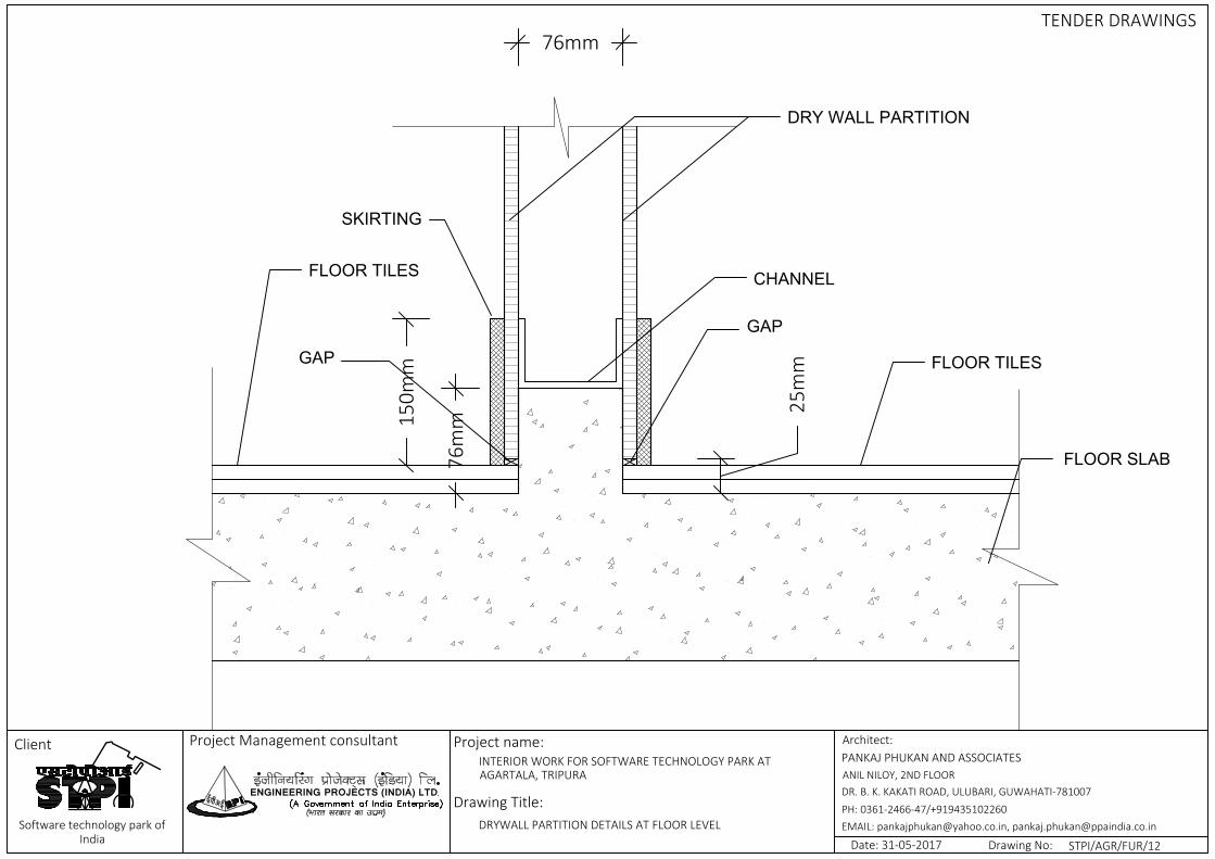
76m
m
25m
m
150m
m
SKIRTING
FLOOR TILES
DRY WALL PARTITION
FLOOR TILES
CHANNEL
FLOOR SLAB
76mm
GAP
GAP
DRYWALL PARTITION DETAILS AT FLOOR LEVEL
ENGINEERING PROJECTS (INDIA) LTD
Client Project Management consultant Architect:PANKAJ PHUKAN AND ASSOCIATESANIL NILOY, 2ND FLOORDR. B. K. KAKATI ROAD, ULUBARI, GUWAHATI-781007PH: 0361-2466-47/+919435102260EMAIL: [email protected], [email protected] technology park of
India
Project name:
Drawing Title:
INTERIOR WORK FOR SOFTWARE TECHNOLOGY PARK ATAGARTALA, TRIPURA
Date: 31-05-2017 Drawing No: STPI/AGR/FUR/12
TENDER DRAWINGS
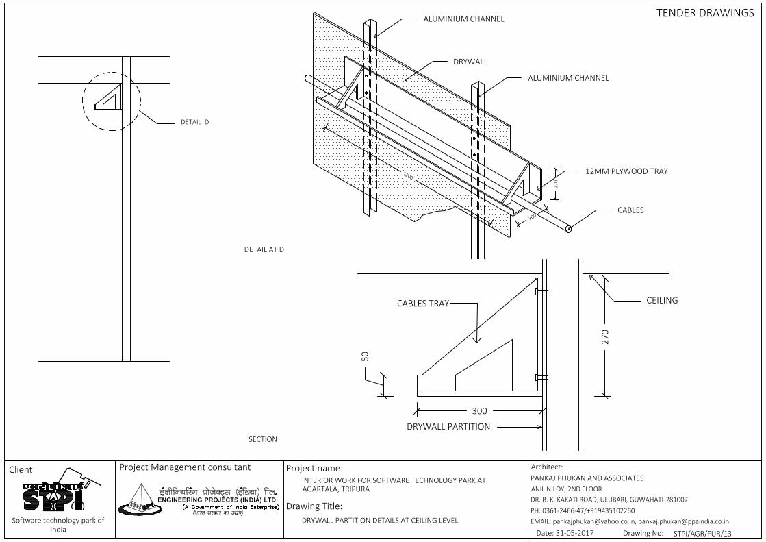
DETAIL D
DRYWALL
ALUMINIUM CHANNEL
12MM PLYWOOD TRAY
270
300
1200
CABLES
ALUMINIUM CHANNEL
300
50
270
CEILING
DRYWALL PARTITION
CABLES TRAY
DRYWALL PARTITION DETAILS AT CEILING LEVEL
ENGINEERING PROJECTS (INDIA) LTD
Client Project Management consultant Architect:PANKAJ PHUKAN AND ASSOCIATESANIL NILOY, 2ND FLOORDR. B. K. KAKATI ROAD, ULUBARI, GUWAHATI-781007PH: 0361-2466-47/+919435102260EMAIL: [email protected], [email protected] technology park of
India
Project name:
Drawing Title:
INTERIOR WORK FOR SOFTWARE TECHNOLOGY PARK ATAGARTALA, TRIPURA
Date: 31-05-2017 Drawing No: STPI/AGR/FUR/13
TENDER DRAWINGS
DETAIL AT D
SECTION
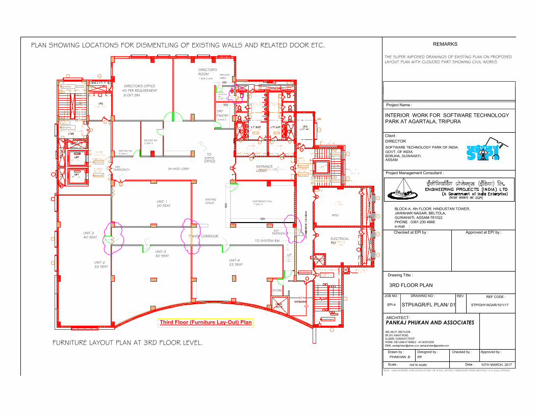
SYSTEM ROOM
3017
4433
Third Floor (Furniture Lay-Out) Plan
SYSTEM ROOM
EMERGENCYEXIT
WAITINGSPACE
3M WIDE LOBBY
DIRECTOR'SROOM
DIRECTOR'S OFFICE
TO STPI'SOFFICE
AS PER REQUIREMENT
7' WIDE CORRIDOR
PRIVATEAREA
FOYERCHANGING/RM
PANTRYDRY
CONFERENCE HALL
TO SYSTEM RM
STORE
UP
ENTRANCELOBBY
8.0X7.8M
UNIT-233 SEAT
UNIT-330 SEAT
UNIT-423 SEAT
7.8X8.0 MAX
2.4X1.9
2.4X3.3
EMERGENCYEXIT
ELECTRICALRM
AHU
PANKAJ PHUKAN AND ASSOCIATESANIL NILOY, 2ND FLOOR.
DR. B.K. KAKATI ROAD,
ULUBARI, GUWAHATI-781007
PHONE: 0361-2466-47/ MOBILE : +91 9435102280
EMAIL :[email protected], [email protected]
NOTE : UNAUTHORISED DUPLICATION IN PART OR IN FULL WITHOUT PERMISSION FROM ARCHITECT IS A LEGAL OFFENCE
FURNITURE LAYOUT PLAN AT 3RD FLOOR LEVEL.
UNIT-120 SEAT
UNIT-240 SEAT
7.6X5.3
RECORD RM2.8X4.5
MEETING RM3.6X4.5
2653
2555
56
94
8289
PLAN SHOWING LOCATIONS FOR DISMENTLING OF EXISTING WALLS AND RELATED DOOR ETC.
THE SUPER IMPOSED DRAWINGS OF EXISTING PLAN ON PROPOSED LAYOUT PLAN WITH CLOUDED PART SHOWING CIVIL WORKS

1200
SYSTEM ROOM
3017
4433
Fourth Floor (Furniture Lay-Out) Plan
4TH FLOOR
SYSTEM ROOM
EMERGENCYEXIT
LIBRARY
REFRESMENT ZONE
WASH BASIN
WAITINGSPACE
PASSAGE
3M WIDE LOBBY
TO SYSTEM RM
UNIT-120 SEAT
UNIT-240 SEAT
UNIT-330 SEAT
UNIT-423 SEAT
ENTRANCELOBBY
MEETING RM
7.6X5.9
5.4X4.5
7.8X8.0M
ELECTRICALRM
AHU
PANKAJ PHUKAN AND ASSOCIATESANIL NILOY, 2ND FLOOR.
DR. B.K. KAKATI ROAD,
ULUBARI, GUWAHATI-781007
PHONE: 0361-2466-47/ MOBILE : +91 9435102280
EMAIL :[email protected], [email protected]
NOTE : UNAUTHORISED DUPLICATION IN PART OR IN FULL WITHOUT PERMISSION FROM ARCHITECT IS A LEGAL OFFENCE
FURNITURE LAYOUT PLAN AT 4TH FLOOR LEVEL.
LOBBY LOBBY
SCREEN
CLASS ROOM TYPESEMINAR HALL7.7X12.6M
PLAN SHOWING LOCATIONS FOR DISMENTLING OF EXISTING WALLS AND RELATED DOOR ETC.
THE SUPER IMPOSED DRAWINGS OF EXISTING PLAN ON PROPOSED LAYOUT PLAN WITH CLOUDED PART SHOWING CIVIL WORKS