FLOOR FINISHES AND PAVING - Engineering...
19
Project : “Civil, Electrical and other utility services for package -Civil- II (Rotable complex) VOLUME –II. TECHNICAL SPECIFICATIONS FOR TENDER NO.NK/FW/CAP-ROH-577/2010-11 Page 1 of 494 FLOOR FINISHES AND PAVING 13.1 Indian Standards The following IS with latest revision apply to this section: I.S. No Subject 653-1980 Specification for sheet linoleum (second revision) 777-1970 Specification for glazed earthenware tiles (first revision with Amdt.No.1) 809-1970 Specification for rubber flooring materials for general purposes (first revision) 1195-1978 Specification for bitumen mastic for flooring (second revision) 1237-1980 Specification for cement concrete flooring tiles (first revision) 1580-1969 Specification for bituminous compound for waterproofing and caulking purposes (first revision) 2114-1984 Code of practice for laying in situ terrazzo floor (first revision) 2508-1984 Specification for-low density polythene films (second revision) 3461-1980 Specification for PVC asbestos floor tiles 3462-1986 Specification for flexible PVC flooring (first revision) 4457-1982 Specification for ceramic unglazed vitreous acid resistant tiles (first revision) 8042-1978 Specification for white Portland cement (first revision) MATERIALS 13.2 Cement Cement shall be ordinary Portland Cement 43 grade conforming to IS 8112. 13.2.1 White cement: White cement shall conform IS 8042 specification for white Portland cement. 13.3 Aggregates Coarse and fine aggregates for cement concrete and granolithic concrete shall conform to IS 383. 13.3.1 Aggregates for granolithic concrete shall consist of crushed granite, basalt, trap or quartzite. The aggregate crushing value shall not exceed 30 per cent. The grading of aggregates shall be as given below IS Sieve Designation Percentage by Coarse Aggregate Weight passing IS Fine Aggregate Zone 1 Sieve Zone 2 12.5 90 to 100 10 40 to 85 90 to 100 90 to 100 4.75 0 to 10 60 to 95 75 to 100 2.36 30 to 70 55 to 90 1.18 30 to 70 55 to 90 600 micron 15 to 34 35 to 59 300 micron 5 to 20 8 to 30 150 micron 0 to 10 0 to 10 13.3.2 Sand for mortar for laying slab/ tiles shall conform to IS 2116 as specified in Brick work. 13.4 to 13.12 DELETED
Transcript of FLOOR FINISHES AND PAVING - Engineering...
Project : “Civil, Electrical and other utility services for package -Civil- II (Rotable complex) VOLUME –II. TECHNICAL SPECIFICATIONS FOR TENDER NO.NK/FW/CAP-ROH-577/2010-11
Page 1 of 494
FLOOR FINISHES AND PAVING
13.1 Indian Standards
The following IS with latest revision apply to this section:
I.S. No Subject
653-1980 Specification for sheet linoleum (second revision)
777-1970 Specification for glazed earthenware tiles (first revision with Amdt.No.1)
809-1970 Specification for rubber flooring materials for general purposes (first revision)
1195-1978 Specification for bitumen mastic for flooring (second revision)
1237-1980 Specification for cement concrete flooring tiles (first revision)
1580-1969 Specification for bituminous compound for waterproofing and caulking purposes (first revision)
2114-1984 Code of practice for laying in situ terrazzo floor (first revision)
2508-1984 Specification for-low density polythene films (second revision)
3461-1980 Specification for PVC asbestos floor tiles
3462-1986 Specification for flexible PVC flooring (first revision)
4457-1982 Specification for ceramic unglazed vitreous acid resistant tiles (first revision)
8042-1978 Specification for white Portland cement (first revision) MATERIALS
13.2 Cement
Cement shall be ordinary Portland Cement 43 grade conforming to IS 8112.
13.2.1 White cement: White cement shall conform IS 8042 specification for white Portland cement.
13.3 Aggregates
Coarse and fine aggregates for cement concrete and granolithic concrete shall conform to IS 383.
13.3.1 Aggregates for granolithic concrete shall consist of crushed granite, basalt, trap or quartzite. The aggregate crushing value shall not exceed 30 per cent. The grading of aggregates shall be as given below
IS Sieve Designation Percentage by
Coarse Aggregate Weight passing IS Fine
Aggregate Zone 1 Sieve Zone 2
12.5 90 to 100
10 40 to 85 90 to 100 90 to 100
4.75 0 to 10 60 to 95 75 to 100
2.36 30 to 70 55 to 90
1.18 30 to 70 55 to 90
600 micron 15 to 34 35 to 59
300 micron 5 to 20 8 to 30
150 micron 0 to 10 0 to 10
13.3.2 Sand for mortar for laying slab/ tiles shall conform to IS 2116 as specified in Brick work.
13.4 to 13.12 DELETED
Project : “Civil, Electrical and other utility services for package -Civil- II (Rotable complex) VOLUME –II. TECHNICAL SPECIFICATIONS FOR TENDER NO.NK/FW/CAP-ROH-577/2010-11
Page 2 of 494
SIGNATURE OF TENDERER WITH SEAL EMPLOYER
13.13 Polythene Film
Polythene film shall comply with relevant IS 2508-1984 , Specification for high density polythene films. The film shall be of approved colour. The film shall be uniform in colour, texture and finish. The film shall be free from pinholes and substantially free from undispersed raw materials, streaks, particles of foreign matter and other visible defects such as holes, tears, and blisters. The edges shall be free from cracks and cuts. The laying of the film shall be done without any folding and shall have overlaps as specified.
13.14 GRANOLITHIC FLOORING :
Base Concrete:
Flooring shall be laid on base concrete or suspended slab where so provided. The base concrete shall be provided with the slopes required for the flooring. Flooring in verandah courtyard kitchens & baths shall have slope ranging from1: 48 to 1: 60 depending upon location and as decided by the Engineer-in-Charge. Floors in water closet portion shall have slope of 1: 30 or as decided by the Engineer -in-Charge to drain off washing water. Plinth masonry off set shall be depressed so as to allow the base concrete to rest on it.
If the base is of lean cement concrete, the flooring shall be commenced preferably within 48 hours of the laying of base concrete. The surface of the base shall be roughened with steel wire brushes without disturbing the concrete. Immediately before laying the flooring, the base shall be wetted and a coat of cement slurry at 2 kg of cement spread over an area of one sqm so as to get a good bond between the base and concrete floor.
If the Granolithic flooring is to be laid directly on the RCC suspended slab, the top surface of RCC slab shall be cleaned and the laitance shall be removed and a coat of cement slurry at 2 kg of cement spread over an area of one sqm so as to get a good bond between the base and concrete floor.
Thickness:
The thickness of floor shall be as specified in the description of the item.
Laying
Panels
Flooring of specified thickness shall be laid in the pattern including the border/or as .given in the drawings or as directed by the Engineer-in-Charge. The border panels shall not exceed 450 mm in width and the joints in the border in line with panel joints. The panels shall be of uniform size and no dimension of a panel shall exceed 2 m and the area of a panel shall not be more than 2 sqm.
Laying of flooring with strips
Normally Granolithic concrete flooring shall be laid in one operation using glass/plain asbestos/alu -minium/PVC/brass strips or any other strips as required as per drawing or as specified or as per instructions of the Engineer-in-Charge, at the junction of two panels. This method ensures uniformity in colour of all the panels and straightness at the junction of the panels. 4 mm thick glass strips or 5 mm thick plain asbestos sheet, 2 mm PVC strips or 2 mm aluminum or brass strips , strip width shall be equal to specified floor thickness and shall be fixed with their tops at proper level, giving required slopes. Cost of providing and fixing strips as specified in item shall be included in the quoted rate. The top of Strip shall be checked to match the required level.
Concreting:
Granolithic concrete shall be placed in the panels and be leveled with the help of straight edge and trowel and beaten with a wooden 'Thapy' or mason's trowel. The blows shall be fairly heavy in the beginning but as consolidation takes place, light rapid strokes shall be given. Beating shall cease as soon as the surface is found covered with a thin layer of cream of mortar. The evenness of the surface shall be tested with straight edge and made true to required slopes. While laying concrete, care shall be taken to see that the strips are not damaged/disturbed by the labourers. The tops of strips shall be visible clearly after finishing with cement slurry.
Laying of flooring without strips:
Project : “Civil, Electrical and other utility services for package -Civil- II (Rotable complex) VOLUME –II. TECHNICAL SPECIFICATIONS FOR TENDER NO.NK/FW/CAP-ROH-577/2010-11
Page 3 of 494
SIGNATURE OF TENDERER WITH SEAL EMPLOYER
Laying of cement concrete flooring in alternate panels may be allowed by the Engineer-in-Charge in case strips are not to be provided.
Shuttering:
The panels shall be bounded by angle iron or flats. The angle iron/flat shall have the same depth as the concrete flooring. These shall be fixed in position, with their top at proper level giving required slopes. The surface of the angle iron or flats, to come in contact with concrete shall be smeared with soap solution or non-sticking oil (Form oil or raw linseed oil) before concreting. The flooring shall butt against the unplastered masonry wall.
At any cost the forms projecting above the desired thickness shall only be permitted.The top edge of the form shall be exactly at the top level of the flooring.
Concreting:
The concreting shall be done in the manner described under sub head Laying of flooring with strips. The angle iron/flats used for shuttering, shall be removed on the next day of the laying of cement concrete. The ends thus exposed shall be repaired, if damaged with cement mortar 1: 2 (1 cement: 2 sand) and allowed to set for minimum period of 24 hours. The alternate panels shall then be cleaned of dust, mortar, droppings etc. and concrete laid. While laying concrete, care shall be taken to see that the edges of the previously laid panels are not damaged and fresh mortar is not splashed over them. The joints between the panels should come out as fine straight lines.
Finishing
The finishing of the surface shall follow immediately after the cessation of beating. The surface shall be left for some time; till moisture disappears from it or surplus water can be mopped up. Use of dry cement or cement and sand mixture sprinkled on the surface to stiffen the concrete or absorb excessive moisture shall not be permitted. Excessive trowelling shall be avoided.
Fresh cement shall be mixed with water to form a thick slurry and spread at the rate of 2 kg of cement over an area of one sqm of flooring while the flooring concrete is still green. The cement slurry shall then be properly processed and finished smooth.
The edges of sunk floors shall be finished and rounded with cement mortar 1: 2 (1 cement: 2 coarse sand) and finished with a floating coat of neat cement.
The junctions of floor with wall plaster, dado or skirting shall be rounded off where so specified.
The men engaged on finishing operations shall be provided with raised wooden platform to sit on so as to prevent damage to new work.
Curing
The curing shall be done for a minimum period of ten days or as directed by the consultant. Curing shall not be commenced until the top layer has hardened. Covering with empty gunnies shall be avoided as the colour of the flooring is likely to be bleached due to the remanents of cement dust from the bags.
Precautions
Concreting shall not be done when the temperature falls below 4°C. The concrete placed shall be protected against frost by suitable covering. Concrete damaged by frost shall be removed and work redone. During hot weather, precautions shall be taken to see that the temperature of wet concrete does not exceed 38°C. No concreting shall be laid within half an hour of the closing time of the day, unless permitted by the Engineer in-Charge. To facilitate rounding of junction of skirting, dado and floor, the skirting/dado shall be laid along with the border or adjacent panels of floor.
Protection Against Dampness –
Project : “Civil, Electrical and other utility services for package -Civil- II (Rotable complex) VOLUME –II. TECHNICAL SPECIFICATIONS FOR TENDER NO.NK/FW/CAP-ROH-577/2010-11
Page 4 of 494
SIGNATURE OF TENDERER WITH SEAL EMPLOYER
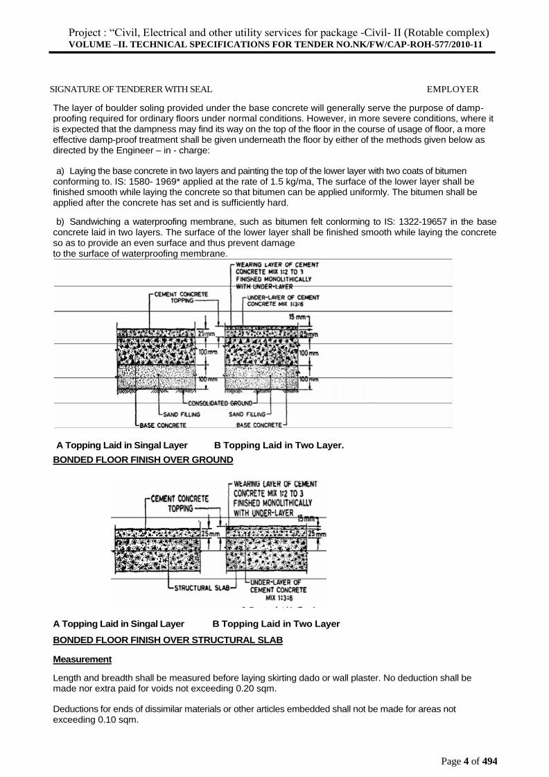
The layer of boulder soling provided under the base concrete will generally serve the purpose of damp- proofing required for ordinary floors under normal conditions. However, in more severe conditions, where it is expected that the dampness may find its way on the top of the floor in the course of usage of floor, a more effective damp-proof treatment shall be given underneath the floor by either of the methods given below as directed by the Engineer – in - charge:
a) Laying the base concrete in two layers and painting the top of the lower layer with two coats of bitumen conforming to. IS: 1580- 1969* applied at the rate of 1.5 kg/ma, The surface of the lower layer shall be finished smooth while laying the concrete so that bitumen can be applied uniformly. The bitumen shall be applied after the concrete has set and is sufficiently hard.
b) Sandwiching a waterproofing membrane, such as bitumen felt conlorming to IS: 1322-19657 in the base concrete laid in two layers. The surface of the lower layer shall be finished smooth while laying the concrete so as to provide an even surface and thus prevent damage to the surface of waterproofing membrane.
A Topping Laid in Singal Layer B Topping Laid in Two Layer.
BONDED FLOOR FINISH OVER GROUND
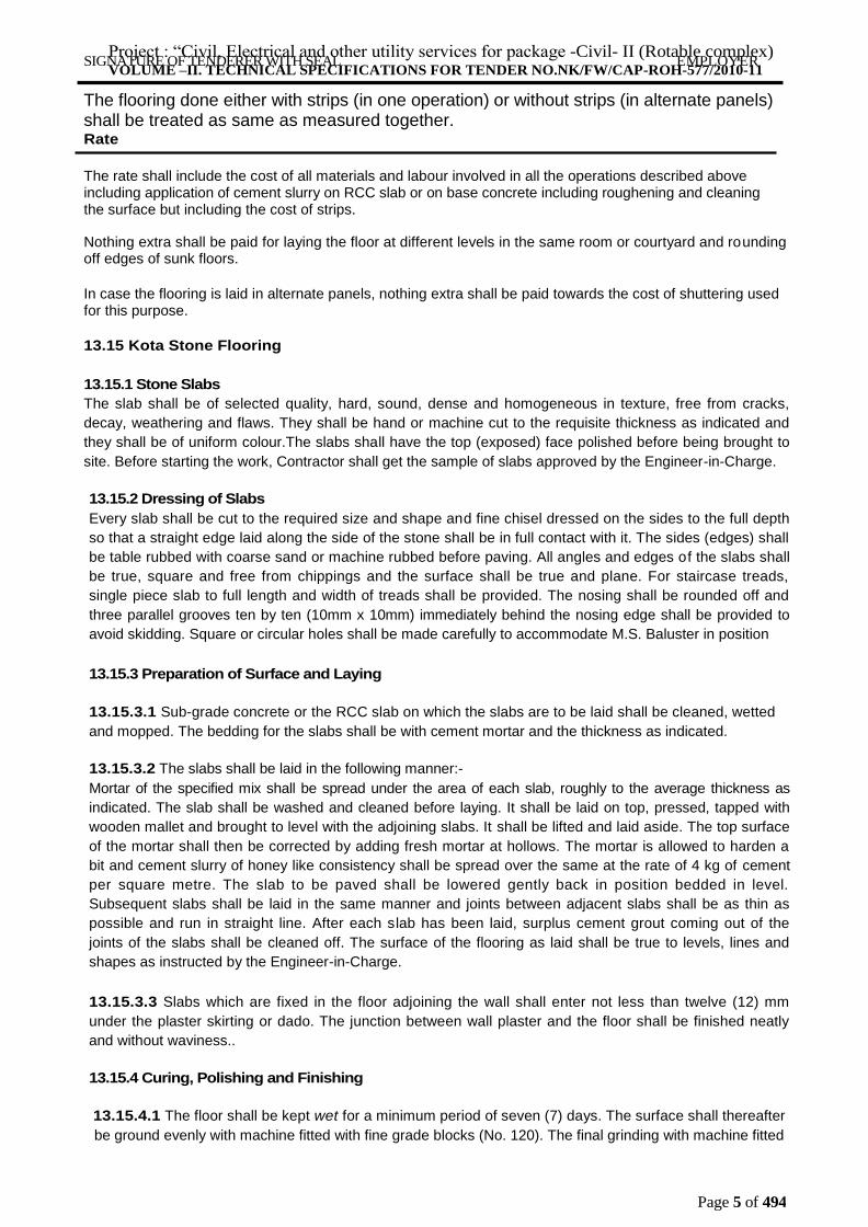
A Topping Laid in Singal Layer B Topping Laid in Two Layer
BONDED FLOOR FINISH OVER STRUCTURAL SLAB
Measurement
Length and breadth shall be measured before laying skirting dado or wall plaster. No deduction shall be made nor extra paid for voids not exceeding 0.20 sqm.
Deductions for ends of dissimilar materials or other articles embedded shall not be made for areas not exceeding 0.10 sqm.
Project : “Civil, Electrical and other utility services for package -Civil- II (Rotable complex) VOLUME –II. TECHNICAL SPECIFICATIONS FOR TENDER NO.NK/FW/CAP-ROH-577/2010-11
Page 5 of 494
SIGNATURE OF TENDERER WITH SEAL EMPLOYER
The flooring done either with strips (in one operation) or without strips (in alternate panels) shall be treated as same as measured together. Rate
The rate shall include the cost of all materials and labour involved in all the operations described above including application of cement slurry on RCC slab or on base concrete including roughening and cleaning the surface but including the cost of strips.
Nothing extra shall be paid for laying the floor at different levels in the same room or courtyard and rounding off edges of sunk floors.
In case the flooring is laid in alternate panels, nothing extra shall be paid towards the cost of shuttering used for this purpose.
13.15 Kota Stone Flooring
13.15.1 Stone Slabs
The slab shall be of selected quality, hard, sound, dense and homogeneous in texture, free from cracks,
decay, weathering and flaws. They shall be hand or machine cut to the requisite thickness as indicated and
they shall be of uniform colour.The slabs shall have the top (exposed) face polished before being brought to
site. Before starting the work, Contractor shall get the sample of slabs approved by the Engineer-in-Charge.
13.15.2 Dressing of Slabs
Every slab shall be cut to the required size and shape and fine chisel dressed on the sides to the full depth
so that a straight edge laid along the side of the stone shall be in full contact with it. The sides (edges) shall
be table rubbed with coarse sand or machine rubbed before paving. All angles and edges of the slabs shall
be true, square and free from chippings and the surface shall be true and plane. For staircase treads,
single piece slab to full length and width of treads shall be provided. The nosing shall be rounded off and
three parallel grooves ten by ten (10mm x 10mm) immediately behind the nosing edge shall be provided to
avoid skidding. Square or circular holes shall be made carefully to accommodate M.S. Baluster in position
13.15.3 Preparation of Surface and Laying
13.15.3.1 Sub-grade concrete or the RCC slab on which the slabs are to be laid shall be cleaned, wetted
and mopped. The bedding for the slabs shall be with cement mortar and the thickness as indicated.
13.15.3.2 The slabs shall be laid in the following manner:-
Mortar of the specified mix shall be spread under the area of each slab, roughly to the average thickness as
indicated. The slab shall be washed and cleaned before laying. It shall be laid on top, pressed, tapped with
wooden mallet and brought to level with the adjoining slabs. It shall be lifted and laid aside. The top surface
of the mortar shall then be corrected by adding fresh mortar at hollows. The mortar is allowed to harden a
bit and cement slurry of honey like consistency shall be spread over the same at the rate of 4 kg of cement
per square metre. The slab to be paved shall be lowered gently back in position bedded in level.
Subsequent slabs shall be laid in the same manner and joints between adjacent slabs shall be as thin as
possible and run in straight line. After each slab has been laid, surplus cement grout coming out of the
joints of the slabs shall be cleaned off. The surface of the flooring as laid shall be true to levels, lines and
shapes as instructed by the Engineer-in-Charge.
13.15.3.3 Slabs which are fixed in the floor adjoining the wall shall enter not less than twelve (12) mm
under the plaster skirting or dado. The junction between wall plaster and the floor shall be finished neatly
and without waviness..
13.15.4 Curing, Polishing and Finishing
13.15.4.1 The floor shall be kept wet for a minimum period of seven (7) days. The surface shall thereafter
be ground evenly with machine fitted with fine grade blocks (No. 120). The final grinding with machine fitted
Project : “Civil, Electrical and other utility services for package -Civil- II (Rotable complex) VOLUME –II. TECHNICAL SPECIFICATIONS FOR TENDER NO.NK/FW/CAP-ROH-577/2010-11
Page 6 of 494
SIGNATURE OF TENDERER WITH SEAL EMPLOYER
with the finest grade grit blocks (No. 320) shall be carried out the day after the first grinding described
above or before handing over the floor, as ordered by the Engineer-in-Charge.
13.15.4.2 For small areas or where circumstances so require, hand polishing may be permitted in lieu of
machine polishing after laying. For hand polishing the following Carborundum stones shall be used.
1st grinding - Medium Grade Stone (No.8)
Final Grinding - Fine Grade (No. 120)
13.15.4.3 In all other respects, the process shall be similar as for machine polishing.
13.15.4.4 After the final polish, oxalic acid shall be dusted over the surface at the rates of thirty three (33)
gms. per square metre sprinkled with water and rubbed hard with pad of wooden rags. The following day
the floor shall be wiped with a moist rag and dried with a soft cloth and finished clean.
13.15.4.5 If any slab is disturbed or damaged, it shall be refitted or replaced, properly jointed and polished.
The finished floor shall not sound hollow when tapped with wooden mallet.
13.16 WEAR RESISTANCE FLOORING BY USE OF VACCUM, DEWATERING METHOD AND POWER TROWELLING METHOD WITH A SKIM FLOATER:
1. Concrete shall be laid between the steel forms and a precast concrete rail acting, as a stop end and also 'rail to be used for surface vibration.
2 The concrete thus laid shall be vibrated with poker vibrator. During poker vibration, proper compaction of coarse aggregates, fine aggregates and cement shall be obtained. The surface will be then finished in level with the help of surface vibrator to give a dense level surface of concrete.
3 Vacuum dewatering method will be used to remove excess water from the laid concrete and filler pad and suction mat shall be laid on the freshly laid concrete which will not allow cement paste to flow out, and the suction pump are then started immediately to remove the excess water. The suction time normally is 20 to 30 minutes. This vacuum process will enable to remove 15 to 25 % of water content and making the surface hard enough to-enable to carry the floating operations.
4 The top surface after removal of mat shall be floated with a mechanical skim floater with trowelling blade to enable the top surface to grind and give a uniform water resistance surface on top. Under no circumstances neat Cement be sprinkled directly on concrete surface to absorb bleed water as surface scaling may occur later. Similarly water should not be applied between trowelling operation as it may cause surface weakness. Minimum two passes shall be carried out. The surface shall then be watered and cured as per clause
The vacuum dewatering process consists of leveling, compacting and vacuum dewatering the concrete flooring by using vibrating screed, vacuum pumps, suction mats, filter pads, accessories etc. The sequence of operation shall be placing of concrete, vibration, vacuum treatment and floating and the operation shall follow immediately behind each other.
The contractor shall have persons well experienced in the vacuum dewatering process, and in the operation of all related equipments. All process equipment to be used shall be in good working condition and shall be subject to the approval of the Engineer.
The work should be planned well in advance with a view to determine areas to be concreted daily, the required number of equipment, size of vacuum mats, length of vacuum hoses, arrangement of rails, screeds etc.
The area to be concreted shall be thoroughly cleaned, reinforced checked and got approved by the Engineer. Then the specified grade of concrete shall be placed in position without any segregation and properly vibrated.
Immediately after placement of concrete, the vibrating screed, fixed at the proper position to achieve the required specified finished level, shall be allowed to run over the concrete on a true surface to level the
Project : “Civil, Electrical and other utility services for package -Civil- II (Rotable complex) VOLUME –II. TECHNICAL SPECIFICATIONS FOR TENDER NO.NK/FW/CAP-ROH-577/2010-11
Page 7 of 494
SIGNATURE OF TENDERER WITH SEAL EMPLOYER
concrete. For better consolidation proper surcharge of concrete should be maintained in front of the leading edge of the screed and the vibrating screed shall be allowed to move forward rapidly. The concrete surface shall be screeded high by 2 of the slab's thickness to compensate for the compaction caused by the vacuum dewatering process. (Slabs which have an aggregate hardener shall have compensation made to maintain elevation.)
Immediately after leveling the concrete shall be covered with filter pads and suction mats in strict accordance with the recommendation of the, Manufacturer to' have the slab fully dewatered. The suction mat shall extend 100 mm beyond the edge of the filter pad on all sides. The pads shall extend to within 100 mm of the edges of concrete slab, and the mats shall cover entire slab. Before connecting the hose on the suction mat to the vacuum pump, the edges of the mat shall be smoothed to enable, an airtight seal to be created. A vacuum shall then be applied to the mat. After a minute the gauge on the vacuum pump should indicate a minimum vacuum of 0.70 atmospheres (24.0 in Hg) and if not, the mat must be checked for leakage. For concrete that dewaters readily the vacuum should then be maintained at 0.70-0.80 atmosphere (24.0-25.5 in Hg). For concrete which dewaters less efficiently (eg. Air-entrained concrete) the vacuum shall then be reduced to 0.50-0.60 atmospheres (15.0-18.0 in Hg). After approximately 10 minutes the vacuum can then be increased to 0.80 atmospheres.
The vacuum shall be maintained for at least 3 minutes per 25 mm of concrete thickness at 0.80 atmospheres. (Where aggregate hardeners are specified, sufficient moisture shall be maintained to meet Manufacturer's requirements). The suction mats and filter pads shall then be removed and move to the next section in a leapfrog manner. The vacuum dewatering can be stopped when light footprints only are left m the concrete when stepped upon. A suitable suction time can also be checked with. a Proctor-apparatus, which should show 1.5-2 Kg / sq cm. Upon removal of the suction mats and filter pads the concrete shall be power floated with out delay until all imprints from the vacuum process are removed. If crusting occurs, the floating operation must be delayed till the concrete carries the machine.
The higher speed is recommended for the floating operation. The passes with the floating disc should be made in the junction of two mats in order to avoid risk of cracking. .
The waiting time after the floating operation depends on concrete temperature and humidity and varies from 10 minutes to 2 hours.
The trowelling operation cannot take place before the concrete has hardened enough to carry the machine i.e., the trowelling blades will not leave any marks on the concrete. Repeated trowelling, with intervals between the passes, which are adapted to the setting of the concrete, greatly improves the surface characteristics. The surface will be more wear resistant and less dusty.
Atleast two passes are recommended for floors, which are not to be covered.
Vacuum dewatered concrete should be cured like any quality concrete in order to achieve a good final result. Use curing compounds, plastic sheets or wet burlap.
The contractor has the responsibility for achieving the quality of concrete specified by controlling the concrete mixes, placing, vacuum process, finishing and curing. The concrete technician in charge must be present at the site when work is in progress.
The contractor shall be responsible for mix adjustments, performing necessary tests, correcting deficiencies and trouble shooting in general.
The contractor shall be required to maintain control charts showing individual test results for aggregate graduation, slump, air content and compressive strength.
Joints in Concrete floor (using sealing compound)
General
Joints shall be of the types and dimensions as indicated and shall be located as indicated.
Dummy Joints
The dummy joints shall be 5 mm wide and shall extend vertically from the surface of the slab to a depth
equal to 1/3 to 1/4 of the thickness of the slab. The joint may be formed by depressing into the soft but
Project : “Civil, Electrical and other utility services for package -Civil- II (Rotable complex) VOLUME –II. TECHNICAL SPECIFICATIONS FOR TENDER NO.NK/FW/CAP-ROH-577/2010-11
Page 8 of 494
SIGNATURE OF TENDERER WITH SEAL EMPLOYER
compacted concrete a high tensile mild steel. 'Tee' or flat bar of depth not less than the required depth o f
the joint plus 25 mm. The bar used for forming the groove shall be coated with soft seal or other suitable
lubricant and have built in handles rigidly fixed to facilitate its removal without spalling or crumbling the
edges. When the steel bar is removed, joints shall be nearly reformed immediately with proper tools and
with mortar/fine material from the slab itself. No additional cement mortar shall be used. Alternatively the
slot may be formed by sawing the concrete with a joint cutting machine (diamond cutter) of approved design
within 6 hours of placing under moderate climatic conditions and when the concrete has sufficiently
hardened. Under extreme cold conditions, this period may be suitably increased based on experience. In all
cases, except where cutting is done with saw, the joint edges shall be bull nosed. Care shall be taken that
the edges of the joints are not damaged. The edge shall not stand proud of the concrete slabs.
Construction Joints
The construction joints shall be 10mm wide and straight and vertical though the full thickness of the slab.
The vertical edge of the concrete on the side of the joint shall be treated with a coat of lime.wash or
bituminous paint before the adjacent bay is concreted. A groove 2.5 cm deep and 1 cm wide shall be
formed at the top surface of the joint to receive the sealing compound. The groove shall be formed in the
same manner as that for a dummy joint. The edges of the groove shall be bull-nosed and not stand proud of
the concrete surface.
Expansion Joints
The expansion joints shall be straight and shall extend through the full thickness of the slab and shall be of
the shape and dimensions shown on the drawings. The slab edges adjacent to the joint shall be f ormed
truly vertical. The joints shall be filled with a 2 cm thick filler board. Cold applied joint sealant (polysulphide
or polyurethane) of approved make with minimum ten years of performance guarantee will be used as joint
sealant. The guarantee should be taken in writing from the contractor before the approval of joint sealants.
The technical specifications of the cold applied joint sealants (irrespective of whether polysulphide or
polyurethane) should meet the requirements mentioned in B5-5212,BS4254 and EN-141875- 2003(for
hydrolysis/water resistance test). In addition, the Movement Accommodation Factor (MAF)of the sealant
should be minimum ± 30 %.
The groove to receive the sealing compound may be formed by cutting the extra filler board to the required
depth.
Sealing of Joints
All joints shall be sealed as soon as practicable after 28 days of placing of the slabs.Thejoints shall
be finished flush with the finished concrete surface if the sealing of joints is done in summer and 3mm
below the finished concrete surface, if the sealing of joints is done in winter. After the sealing compound
has hardened, the excess sealing compound, if any, adhering to the slab outside the joints shall be
removed by scraping or otherwise and the surface left clean.The pavement shall be opened to traffic only
after the completion of joint sealing over the entire pavement.
Cleaning of Joints
All foreign materials in the joints shall be removed with pneumatic blower. The joints shall,
thereafter, be cleaned with a coir brush. Fine particles clinging to the concrete faces shall be removed with
the help of an air compressor only to avoid damage to the edges. The joints shall be cleaned and surface
dried before the application of primer.
Application of Primer
The cleaned joint shall be primed with a 20-25mm side painter's brush, while painting, light
pressure shall be applied so that the primer penetrates into the pores of concrete. The primer shall be
applied twice on one side (i.e. by forward and reverse movement of brush) The primer shall be applied in
the thinnest possible complete film and then left for some till the primer feels "tacky" soon after the primer is
applied, the joint is covered with 10-15cm wide paper strips so that no dust is deposited on the primer.
Project : “Civil, Electrical and other utility services for package -Civil- II (Rotable complex) VOLUME –II. TECHNICAL SPECIFICATIONS FOR TENDER NO.NK/FW/CAP-ROH-577/2010-11
Page 9 of 494
SIGNATURE OF TENDERER WITH SEAL EMPLOYER
Sealant joints
Only cold applied Polysulphide or Polyurethane joint sealant of approved make will be used in rigid
pavements. The criteria for selection of the joint sealant will depend on the minimum performance
guarantee of ten years offered by the firm. This performance-based selection would accruebetter cost
effective results rather than using a joint sealant without any guarantee. The technical specifications of the
cold applied joint sealants (irrespective of whether polysulphide or polyurethane) should meet all the
requirements mentioned in B5-5212,BS 4254 and EN- 141875-2003(forhydrolysis/water resistance test).1n
addition, the movement accommodation factor (MAF)of the sealant should be minimum ± 30 %.
While the joints shall be sealed flush with the adjacent pavement surface in summer, in winter they
shall be filled to a depth of 3-4mm below the surface. This procedure will reduce the possibility of ingress of
grit and other foreign matter into the sealing compound as well as dislodging of the hardened sealing
compound under traffic.
Joints in pavement concrete, (using polysulphidef polyurethane material)
General
Joint shall be of the types and dimensions specified and be located in all as directed by Gamson
Engineer. The edges of the groove/joints shall be bull nosed & not stand proud of the concrete surface.
Dummy Joints
The size of joints shall be as indicated/ specified.
.The joint shall be formed using mechanical equipment (diamond cutter) within 6 hour of placing of concrete
under moderate climatic conditions and when the concrete has sufficiently hardened. Cutting or sawing by a
sawing mounted at movable frame and driven mechanically will also be permitted as a method for making
the joint. Care shall be taken that the edge of the joints are not damaged.
In case of sudden rain or storm, the work can be concluded at the dummy joint but the latter will then be
formed into a construction joint.
Construction Joints
Construction joints shall also be provided at places where concreting is stopped due to unforeseen
circumstances. The size of joints shall be as specified and as shown on drawings.
Construction joints shall be straight and vertical through the full thickness of the slab. The vertical edge of
the concrete of the side of the joint shall be treated with a coat of lime
wash or bituminous paint before the adjacent bay is concreted. Agroove of dimension as specified in
contract shall be formed. The groove shall be formed in the same manner as that for a dummy joint.
Expansion Joints
The expansion joints shall consist of a joint filler board as detailed in the drawing. The depth of the non
extruding filler pad Ooint filler board) shall be cut by 25mm from top to prepare the joint.
Joints shall be straight and shall extend through the full thickness of the slab and shall be of the shape and
dimensions shown on the drawings. The slab edge adjacent to the joint shall be formed truly vertical. The
joints shall be filled with approved joint filler as per clause 20.B.7.10.4.
Before the provision of expansion joint, the face of the already laid concrete slab shall be painted with the
approved primer at the rate of 2.6 liters per 10 square metres. The expansion pad shall be properly cut to
shape. Bond breaker tape shall be applied on the top face of the pad before inserting the dosed cell backup
rod. It shall then be placed in position abutting the painted face of the already laid concrete slab. The
adjacent slab shall then be concreted. The faces of the pad against which the new concrete slab is to be
Project : “Civil, Electrical and other utility services for package -Civil- II (Rotable complex) VOLUME –II. TECHNICAL SPECIFICATIONS FOR TENDER NO.NK/FW/CAP-ROH-577/2010-11
Page 10 of 494
SIGNATURE OF TENDERER WITH SEAL EMPLOYER
laid shall also be painted with the approved primer before laying the concrete. While concreting a neat
groove as per drawing shall be formed on top of the pad taking care that the edges are absolutely straight
and that the groove so made does not get filled with any material like concrete, mortar and other rubbish.
The groove to receive the sealant may be formed by cutting the excess filler board material to the required
depth.
Expansion joints shall be provided both longitudinally and transverse direction at spacing as shown on
drawing or as directed by Engineer-in-Charge.
Procedure Of Joint Filling With Polysulphide / Polyurethane Sealant
The technical specifications of the cold applied joint sealants (irrespective of whether polysulphide or
polyurethane) should meet all the requirements mentioned in BS-5212,BS 4254and EN-141875-2003(for
hydrolysis/water resistance test). In addition, the Movement Accommodation Factor (MAF)of the sealant
should be minimum:f: 30 %.The criteria for selection of the joint sealant of approved make will be a
minimum performance guarantee of ten years offered by the firm. This performance-based selection would
accrue better cost effective results rather than using a joint sealant without any guarantee. Contractor shall
not procure the materialsrequired for joint filling unless the samples are approved by the GE and a ten
years of guarantee is given in writing by the contractor. The primer and sealant shall got tested by GE from
a reputed testing laboratory who has the NABL accreditations like Indian Rubber Manufacturer's Research
Association's Laboratory /CRRI/IIT/NIT/SEMT Wing, CME Pune beforeapproval. The test certificate shall be
obtained for every 5MTof material incorporated in the work.
Joint Preparation
Before commencing joint sealing operations, the following shall be ensured:-
(a) The groove extends fully across the bay between consecutive longitudinal joints in the case of
transverse joints and is continuous in the case of longitudinal-joints.
(b) No concrete and foreign matter shall be left in the groove.
(c) In case of expansion joint, the filled materials is exposed to the full length of the joint and expansion joint
filler is tightly packed.
(d) Joint surface must be dry, free from dust, coaling, bituminous mastics, concrete curing agencies, mould
release agents, oil, grease and loose particles.
(e) All joints shall be thoroughly cleaned out by compressed air and sanding with emery paper or other
approved means and shall be approved by Engineer-in- Charge before they are sealed.
(f) The cleaned and prepared joints shall be primed on the sides of the joints up to the depth where sealing
component is to be provided and filled with approved sealant.
(g) Wipe out oil and grease by solvent soaked cloth (such as Xylene, Toluene or Acetone or Gardoclean).
(h) Before sealing, insert a bond breaker tape and bond breaker(closed cell polyethylene frame rod)
caulked tightly into the base of the sealing groove to prevent the sealant from adhering to the base of slot.
Width of bond breaker (backup rod) shall be 20 to 25% more than the joint so that there is no seepage of
sealant through joints edges.
Fixing/Masking Tape Fix masking tape to prevent edges of joints becoming dirty due to spillage of sealant at the time of pouring.
Application Of Primer
(i) Suitable primer shall be first applied to the. vertical faces of the concrete joint before pouring cold applied
sealant confirming to specifications given at clause 20.B.7.1 1.5.1, in order to improve the adhesive qualities
of the product. Primer as specified by manufactures shall be applied to the joint vertical surfaces and
allowed to dry for 30 minutes to 2 hours depending on the climatic condition. The surfaces shall be primed
twice @0.075litre (minimum) primer per square metre.
(ii) If the primer film has become completely tack free, the surface must be re-primed before applying the
sealant.
(iii)If the primed areas are left unsealed overnight the primer film must be removed by grit blasting or
grinding and the joints interfaces shall be re-primed.
Project : “Civil, Electrical and other utility services for package -Civil- II (Rotable complex) VOLUME –II. TECHNICAL SPECIFICATIONS FOR TENDER NO.NK/FW/CAP-ROH-577/2010-11
Page 11 of 494
SIGNATURE OF TENDERER WITH SEAL EMPLOYER
Mixing
Mixing and application of sealant will be through mechanical means to avoid any human error. The
mixed product shall be used immediately as per manufacturer's instructions within its pot life i.e. within 30
minute. The mixed sealant should be kept for a few minutes to allow air to escape before commencement
of jointing filling.
Application or Pouring of Sealant
Mixed sealant shall be applied by mechanical means (machine application) based on the
manufacturer's instructions and shall be executed by his approved and trained applicator. Application
temperature of sealant should be in between 5 to 45 degree Celsius (or as per manufacturer's instructions).
It should be filled to a level 2 to 3mm below the top of the pavement leaving a recess to protect the sealant
from damage. To prevent accidental spillage of sealant on the top surface and to give a neat finish masking
tape should be applied on front edges of joint in such a manner that the material will not be spilled on the
exposed surface of the concrete. Any excess filler on the surface of the pavement shall be removed
immediately and the pavement surface cleaned. All necessary precautions as per the manufacturer's
recommendations shan be taken. The sealant should be immediately tooled either with stainless steel or
wooden spatula of the size of the joint to give a smooth finish before it begins to set. Masking tape shall be
removed immediately after the sealant has been tooled. The sealant should be allowed to cure as per
manufacturer's instructions during which period no traffic should be allowed on the pavement.
The test certificate shall be obtained for every 5 MT of material incorporated in the work.
Some Miscellaneous Aspects
(i) The sealant are sensitive to temperature while in storage as well as during mixing. Temperatures for all
phase of handling of the sealing compounds viz mixing, placing and curing conditions must be in
accordance with manufacturer's recommendations.
(ii) All safety precautions during handing and application of these sea lants as prescribed by the
manufacturers shall also be strictly adhered to.
Precautions
(a) Some people are sensitive to resins, hardeners, vapour etc. Therefore it is advisable to use hand
gloves/ goggles and suitable protective clothing.
(b) Avoid application below 1 0DCtemperature.
(c) Avoid application on damp or Moist surfaces.
(d) Do not expose primer to naked flames or other sources of ignition.
(e) Materials to be kept in no smoking area.
(f) Containers should be tightly sealed when not in use.
(g) In the event of fire, extinguish with carbon dioxide or foam.
(h) Should accident skin contact occurs, remove immediately with a resin removing cream, followed by
soap and water. Do not use solvent.
(i) In case of contact with eyes, rinse immediately with plenty of clean water and seek medical advise.
(j) Use only in well ventilated areas.
(k) All consumables (masking tape, empty cartridges etc) should be removed and disposed off safely.
13.17 Epoxy Polyurethane Flooring
Scope of work:
The scope work is laying of self leveling epoxy flooring generally consists of following steps
Surface Preparation
Epoxy Primer -
Epoxy Underlay
Epoxy Polyurethane Self leveling Coat
Project : “Civil, Electrical and other utility services for package -Civil- II (Rotable complex) VOLUME –II. TECHNICAL SPECIFICATIONS FOR TENDER NO.NK/FW/CAP-ROH-577/2010-11
Page 12 of 494
SIGNATURE OF TENDERER WITH SEAL EMPLOYER
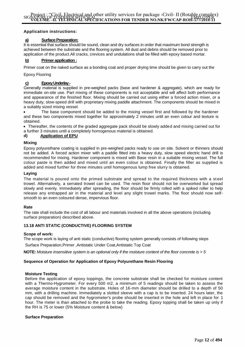
Application instructions:
a) Surface Preparation:
It is essential that surface should be sound, clean and dry surfaces in order that maximum bond strength is achieved between the substrate and the flooring system. All dust and debris should be removed prior to application of the product.All cracks, crevices and undulations shall be filled with epoxy based mortar.
b) Primer application :
Primer coat on the naked surface as a bonding coat and proper drying time should be given to carry out the
Epoxy Flooring
c) Epoxy Underlay -
Generally material is supplied in pre-weighed packs (base and hardener & aggregate), which are ready for immediate on-site use. Part mixing of these components is not acceptable and will affect both performance and appearance of the finished floor. Mixing should be carried out using either a forced action mixer, or a heavy duty, slow-speed drill with proprietary mixing paddle attachment. The components should be mixed in a suitably sized mixing vessel.
The base component should be added to the mixing vessel first and followed by the hardener and these two components mixed together for approximately 2 minutes until an even colour and texture is obtained.
Thereafter, the contents of the graded aggregate pack should be slowly added and mixing carried out for a further 3 minutes until a completely homogenous material is obtained. d) Application of EPU
Mixing
Epoxy polyurethane coating is supplied in pre-weighed packs ready to use on site. Solvent or thinners should not be added. A forced action mixer with a paddle fitted into a heavy duty, slow speed electric hand drill is recommended for mixing. Hardener component is mixed with Base resin in a suitable mixing vessel. The full colour paste is then added and mixed until an even colour is obtained. Finally the filler as supplied is added and mixed further for three minutes until homogenous lump free slurry is obtained.
Laying
The material is poured onto the primed substrate and spread to the required thickness with a st eel trowel. Alternatively, a serrated trowel can be used. The resin floor should not be overworked but spread slowly and evenly. Immediately after spreading, the floor should be firmly rolled with a spiked roller to help release any entrapped air in the material and level any slight trowel marks. The floor should now self - smooth to an even coloured dense, impervious floor.
Rate
The rate shall include the cost of all labour and materials involved in all the above operations (including surface preparation) described above.
13.18 ANTI STATIC (CONDUCTIVE) FLOORING SYSTEM
Scope of work: The scope work is laying of anti static (conductive) flooring system generally consists of following steps
Surface Preparation,Primer ,Antistatic Under Coat,Antistatic Top Coat
NOTE: Moisture insensitive system is an optional only if the moisture content of the floor concrete is > 5
Sequence of Operation for Application of Epoxy Polyurethane Resin Flooring
Moisture Testing Before the application of epoxy toppings, the concrete substrate shall be checked for moisture content with a Thermo-Hygrometer. For every 500 m2, a minimum of 5 readings should be taken to assess the average moisture content in the substrate. Holes of 16-mm diameter should be drilled to a depth of 50 mm, with a drilling machine. Immediately a slotted sleeve with a cap is to be inserted. 24 hours later, the cap should be removed and the hygrometer's probe should be inserted in the hole and left in place for 1 hour. The meter is than attached to the probe to take the reading. Epoxy topping shall be taken up only if the RH is 75 or lower (5% Moisture content & below)
Surface Preparation
Project : “Civil, Electrical and other utility services for package -Civil- II (Rotable complex) VOLUME –II. TECHNICAL SPECIFICATIONS FOR TENDER NO.NK/FW/CAP-ROH-577/2010-11
Page 13 of 494
SIGNATURE OF TENDERER WITH SEAL EMPLOYER
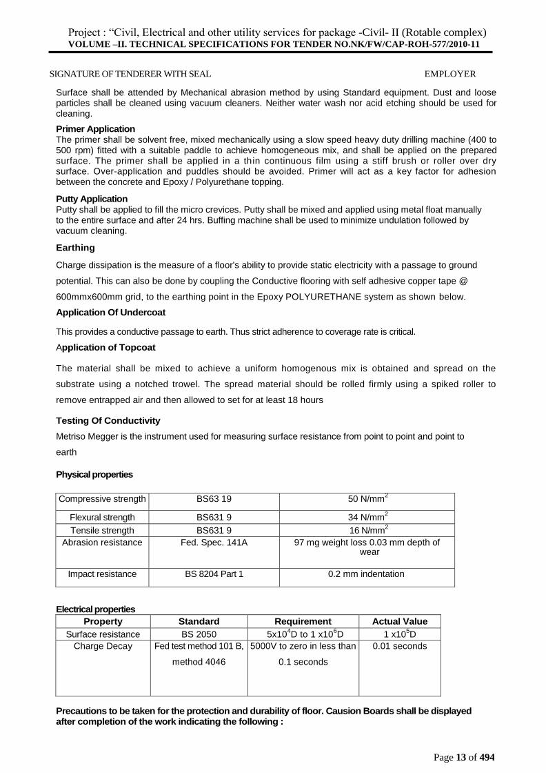
Surface shall be attended by Mechanical abrasion method by using Standard equipment. Dust and loose particles shall be cleaned using vacuum cleaners. Neither water wash nor acid etching should be used for cleaning.
Primer Application The primer shall be solvent free, mixed mechanically using a slow speed heavy duty drilling machine (400 to 500 rpm) fitted with a suitable paddle to achieve homogeneous mix, and shall be applied on the prepared surface. The primer shall be applied in a thin continuous film using a stiff brush or roller over dry surface. Over-application and puddles should be avoided. Primer will act as a key factor for adhesion between the concrete and Epoxy / Polyurethane topping.
Putty Application Putty shall be applied to fill the micro crevices. Putty shall be mixed and applied using metal float manually to the entire surface and after 24 hrs. Buffing machine shall be used to minimize undulation followed by vacuum cleaning.
Earthing
Charge dissipation is the measure of a floor's ability to provide static electricity with a passage to ground
potential. This can also be done by coupling the Conductive flooring with self adhesive copper tape @
600mmx600mm grid, to the earthing point in the Epoxy POLYURETHANE system as shown below.
Application Of Undercoat
This provides a conductive passage to earth. Thus strict adherence to coverage rate is critical.
Application of Topcoat
The material shall be mixed to achieve a uniform homogenous mix is obtained and spread on the
substrate using a notched trowel. The spread material should be rolled firmly using a spiked roller to
remove entrapped air and then allowed to set for at least 18 hours
Testing Of Conductivity
Metriso Megger is the instrument used for measuring surface resistance from point to point and point to
earth
Physical properties
Compressive strength BS63 19 50 N/mm2
Flexural strength BS631 9 34 N/mm2
Tensile strength BS631 9 16 N/mm2
Abrasion resistance Fed. Spec. 141A 97 mg weight loss 0.03 mm depth of wear
Impact resistance BS 8204 Part 1 0.2 mm indentation
Electrical properties
Property Standard Requirement Actual Value
Surface resistance BS 2050 5x10⁴D to 1 x10
6D 1 x10
5D
Charge Decay Fed test method 101 B,
method 4046
5000V to zero in less than
0.1 seconds
0.01 seconds
Precautions to be taken for the protection and durability of floor. Causion Boards shall be displayed after completion of the work indicating the following :
Project : “Civil, Electrical and other utility services for package -Civil- II (Rotable complex) VOLUME –II. TECHNICAL SPECIFICATIONS FOR TENDER NO.NK/FW/CAP-ROH-577/2010-11
Page 14 of 494
SIGNATURE OF TENDERER WITH SEAL EMPLOYER
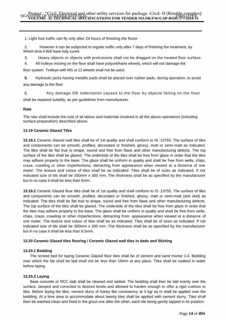
1. Light foot traffic can fly only after 24 hours of finishing the flooor
2. However it can be subjected to regular traffic only after 7 days of finishing the treatment, by Which time it Will have fully cured.
3. Heavy objects or objects with protrusions shall not be dragged on the treated floor surface.
4. All trolleys moving on the floor shall have polyurethane wheels, which will not damage the
floor system. Trolleys with MS or Cl wheels shall not be used.
5. Hydraulic jacks having metallic pads shall be placed over rubber pads, during operation, to avoid
any damage to the floor
6. Any damage OR indentation caused to the f loor by objects fal l ing on the f loor
shall be repaired suitably, as per guidelines from manufacturer.
Rate
The rate shall include the cost of all labour and materials involved in all the above operations (including surface preparation) described above.
13.19 Ceramic Glazed Tiles
13.19.1 Ceramic Glazed wall tiles shall be of 1st quality and shall conform to IS :13753. The surface of tiles
and components can be smooth, profiled, decorated or finished, glossy, matt or semi-matt as indicated.
The tiles shall be flat true to shape, sound and free from flaws and other manufacturing defects. The top
surface of the tiles shall be glazed. The underside of the tiles shall be free from glaze in order that the tiles
may adhere properly to the base. The glaze shall be uniform in quality and shall be free from welts, chips,
craze, crawling or other imperfections, detracting from appearance when viewed at a distance of one
meter. The texture and colour of tiles shall be as indicated. Tiles shall be of sizes as indicated. If not
indicated size of tile shall be 200mm x 300 mm. The thickness shall be as specified by the manufacturer
but in no case it shall be less than 6mm.
13.19.2 Ceramic Glazed floor tiles shall be of 1st quality and shall conform to IS :13755. The surface of tiles
and components can be smooth, profiled, decorated or finished, glossy, matt or semi-matt (anti skid) as
indicated. The tiles shall be flat true to shape, sound and free from flaws and other manufacturing defects.
The top surface of the tiles shall be glazed. The underside of the tiles shall be free from glaze in order that
the tiles may adhere properly to the base. The glaze shall be uniform in quality and shall be free from welts,
chips, craze, crawling or other imperfections, detracting from .appearance when viewed at a distance of
one meter. The texture and colour of tiles shall be as indicated. Tiles shall be of sizes as indicated. If not
indicated size of tile shall be 300mm x 300 mm. The thickness shall be as specified by the manufacturer
but in no case it shall be less than 6.5mm.
13.20 Ceramic Glazed tiles flooring / Ceramic Glazed wall tiles in dado and Skirting
13.20.1 Bedding
The screed bed for laying Ceramic Glazed floor tiles shall be of cement and sand mortar 1:4. Bedding
over which the tile shall be laid shall not be less than 10mm at any place. Tiles shall be soaked in water
before laying.
13.20.2 Laying
Base concrete or RCC slab shall be cleaned and wetted. The bedding shall then be laid evenly over the
surface, tamped and corrected to desired levels and allowed to harden enough to offer a rigid cushion to
tiles. Before laying the tiles, cement slurry of honey like consistency at 3 kg/ sq m shall be applied over the
bedding. At a time area to accommodate about twenty tiles shall be applied with cement slurry. Tiles shall
then be washed clean and fixed in the grout one after the other, each tile being gently tapped in its position

Project : “Civil, Electrical and other utility services for package -Civil- II (Rotable complex) VOLUME –II. TECHNICAL SPECIFICATIONS FOR TENDER NO.NK/FW/CAP-ROH-577/2010-11
Page 15 of 494
SIGNATURE OF TENDERER WITH SEAL EMPLOYER
Project : “Civil, Electrical and other utility services for package -Civil- II (Rotable complex) VOLUME –II. TECHNICAL SPECIFICATIONS FOR TENDER NO.NK/FW/CAP-ROH-577/2010-11
Page 16 of 494
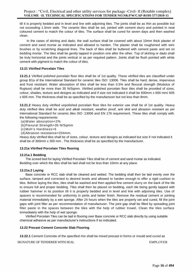
till it is properly bedded and in level and line with adjoining tiles. The joints shall be as thin as possible but
not exceeding 1.5mm wide. The ceramic tiles shall be set, jointed with cement slurry and pointed in neat
coloured cement to match the colour of tiles. The surface shall be cured for seven days and then washed
clean.
In the cases of skirting and dado, the wall surface shall be covered with about 10mm thick plaster of
cement and sand mortar as indicated and allowed to harden. The plaster shall be roughened with wire
brushes or by scratching diagonal lines. The back of tiles shall be buttered with cement paste and set on
bedding mortar. The tiles shall be gently tapped in position one after the other. Top of skirting or dado shall
be truly horizontal and the joints vertical or as per required pattern. Joints shall be flush pointed with white
cement with pigment to match the colour of tiles.
13.21 Vitrified Porcelain Tiles
13.21.1 Vitrified polished porcelain floor tiles shall be of 1st quality. These vitrified tiles are classified under
group B1a of the International Standard for ceramic tiles ISO: 13006. Tiles shall be hard, dense, impervious
and frost resistant. Water absorption of tiles shall be less than 0.5% and flexural strength (Modulus of
Rupture) shall be more than 35 N/Sqmm. Vitrified polished porcelain floor tiles shall be provided of sizes,
colour, shades, texture and designs as indicated and if size not indicated it shall be 600mm x 600 mm/ 605
x 605 mm. The thickness shall be as specified by the manufacturer but not less than 8mm.
13.21.2 Heavy duty vitrified unpolished porcelain floor tiles for exterior use shall be of 1st quality. Heavy
duty vitrified tiles shall be acid and alkali resistant, weather proof, anti skid and abrasion resistant as per
International Standard for ceramic tiles ISO :13006 and EN 176 requirement. These tiles shall comply with.
the following requirements:
(a) Water absorption<2%
(b) Flexural Strength>35 N/Sqmm
(c) Moh's Hardness>6
(d) Abrasion resistance<204mm.
Heavy duty vitrified tiles shall be of sizes, colour, texture and designs as indicated but size if not indicated it
shall be of 300mm x 300 mm . The thickness shall be as specified by the manufacturer.
13.21a Vitrified Porcelain Tiles flooring
13.21a.1 Bedding
The screed bed for laying Vitrified Porcelain Tiles shall be of cement and sand mortar as indicated.
Bedding over which the tiles shall be laid shall not be less than 10mm at any place.
13.21a.2 Laying
Base concrete or RCC slab shall be cleaned and wetted. The bedding shall then be laid evenly over the
surface, tamped and corrected to desired levels and allowed to harden enough to offer a rigid cushion to
tiles. Before laying the tiles, tiles shall be washed and then applied fine cement slurry on the back of the tile
to ensure full and proper bedding. Tiles shall then be placed on bedding, each tile being gently tapped with
rubber hammer in its position till it is properly bedded and in level and line with adjoining tiles. Use of
spacers is recommended for uniformity in joints and better finish. Remove the residual cement or jointing
material immediately by a wet sponge. After 24 hours when the tiles are properly set and cured, fill the joint
gaps with joint filler as per recommendation of manufacturer. The joint gap shall be filled by spreading joint
filler paste in the spaces between the tiles with the help of rubber trowel. Clean the tiles surface
immediately with the help of wet sponge.
Vitrified Porcelain Tiles can be laid in flooring over Base concrete or RCC slab directly by using suitable
chemical adhesive as per manufacturer’s instructions if so indicated.
13.22 Precast Cement Concrete Slab Flooring
13.22.1 Cement Concrete of the specified mix shall be mixed precast in forms or mould and cured as
SIGNATURE OF TENDERER WITH SEAL EMPLOYER
Project : “Civil, Electrical and other utility services for package -Civil- II (Rotable complex) VOLUME –II. TECHNICAL SPECIFICATIONS FOR TENDER NO.NK/FW/CAP-ROH-577/2010-11
Page 17 of 494
specified for precast articles in Section for Concrete. Unless otherwise indicated, the size of slabs shall
not exceed 0.5 Sq m nor be less than 0.1 Sq m. Slabs used in anyone room shall be uniform in size and of
thickness as indicated. The top surface of slabs shall be finished fair and smooth (using additional cement
where indicated) whilst the concrete is green in forms. Exposed edges shall be perfectly fine, square and
well defined.
13.22.2 The slabs shall be bedded and jointed in cement and sand mortar as indicated and Pointed in
cement and sand mortaras indicated. The thickness of bedding mortar shall be not less than 15mm and
thickness of joints shall not exceed 6mm.
13.23 GRANULAR SUB-BASE
13.23.1 SCOPE
This work shall consist of laying and compacting well-graded material on prepared subgrade in accordance with the requirements of Specifications. The material shall be laid in one or more layers as sub-base or lower sub-base and upper sub-base (termed as sub base hereinafter) as necessary according to lines, grades and cross sections shown on the drawings or as directed by the Engineer.
13.23.2 MATERIALS
13.23.2.1 The material to be used for the work shall be natural sand, gravel, crushed stone, or combinations thereof depending upon the grading required. The material shall be free from organic or other deleterious constituents and conform to gradings (given below).
While the gradings in Table -1 are in respect of close-graded granular sub-base materials, one each for maximum particle size of 75 mm, 53 mm and 26.5 mm, the corresponding gradings for the coarse-graded materials for each of the three maximum particle sizes are given at Table -2. The grading to be adopted for a project shall be as specified in the Contract.
13.23.2.2 Physical requirements
The material shall have a 10 per cent fines value of 50 kN or more (for sample in soaked condition) when tested in compliance with BS : 812 (Part 111). The water absorption value of the coarse aggregate shall be determined as per IS :2386 (Part 3); if this value is greater than 2 per cent, the soundness test shall be carried out on the material delivered to site as per IS : 383. For Grading II and III materials, the CBR shall be determined at the density and moisture content likely to be developed in equilibrium conditions which shall be taken as being the density relating to a uniform air voids content of 5 per cent.
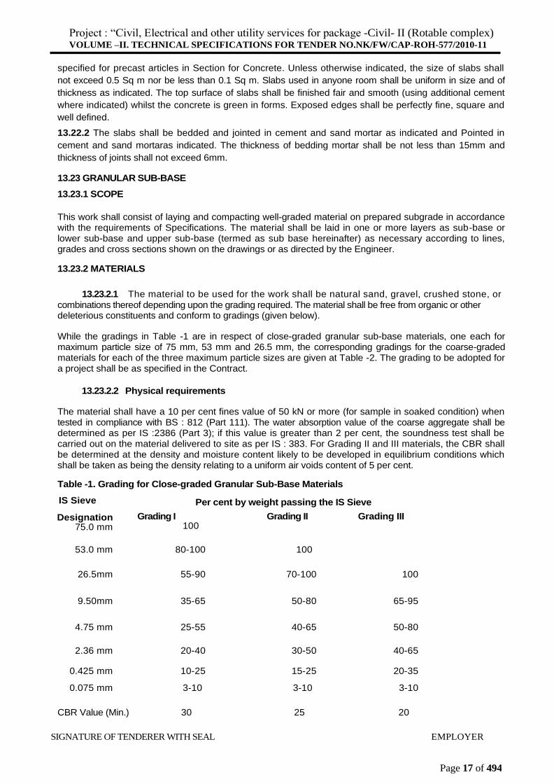
Table -1. Grading for Close-graded Granular Sub-Base Materials
IS Sieve
Designation 75.0 mm
Per cent by weight passing the IS Sieve
Grading I Grading II Grading III 100
53.0 mm 80-100 100
26.5mm 55-90 70-100 100
9.50mm 35-65 50-80 65-95
4.75 mm 25-55 40-65 50-80
2.36 mm 20-40 30-50 40-65
0.425 mm 10-25 15-25 20-35
0.075 mm 3-10 3-10 3-10
CBR Value (Min.) 30 25 20
SIGNATURE OF TENDERER WITH SEAL EMPLOYER
Project : “Civil, Electrical and other utility services for package -Civil- II (Rotable complex) VOLUME –II. TECHNICAL SPECIFICATIONS FOR TENDER NO.NK/FW/CAP-ROH-577/2010-11
Page 18 of 494
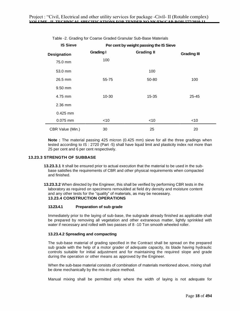
Table -2. Grading for Coarse Graded Granular Sub-Base Materials
IS Sieve
Designation
75.0 mm
Per cent by weight passing the IS Sieve
Grading I Grading II
100
Grading III
53.0 mm 100
26.5 mm 55-75 50-80 100
9.50 mm
4.75 mm 10-30 15-35 25-45
2.36 mm
0.425 mm
0.075 mm <10 <10 <10
CBR Value (Min.) 30 25 20
Note : The material passing 425 micron (0.425 mm) sieve for all the three gradings when tested according to IS : 2720 (Part -5) shall have liquid limit and plasticity index not more than 25 per cent and 6 per cent respectively.
13.23.3 STRENGTH OF SUBBASE
13.23.3.1 It shall be ensured prior to actual execution that the material to be used in the sub-base satisfies the requirements of CBR and other physical requirements when compacted and finished.
13.23.3.2 When directed by the Engineer, this shall be verified by performing CBR tests in the laboratory as required on specimens remoulded at field dry density and moisture content and any other tests for the “quality” of materials, as may be necessary.
13.23.4 CONSTRUCTION OPERATIONS
13.23.4.1 Preparation of sub grade
Immediately prior to the laying of sub-base, the subgrade already finished as applicable shall be prepared by removing all vegetation and other extraneous matter, lightly sprinkled with water if necessary and rolled with two passes of 8 -10 Ton smooth wheeled roller.
13.23.4.2 Spreading and compacting
The sub-base material of grading specified in the Contract shall be spread on the prepared sub grade with the help of a motor grader of adequate capacity, its blade having hydraulic controls suitable for initial adjustment and for maintaining the required slope and grade during the operation or other means as approved by the Engineer.
When the sub-base material consists of combination of materials mentioned above, mixing shall be done mechanically by the mix-in-place method.
Manual mixing shall be permitted only where the width of laying is not adequate for
Project : “Civil, Electrical and other utility services for package -Civil- II (Rotable complex) VOLUME –II. TECHNICAL SPECIFICATIONS FOR TENDER NO.NK/FW/CAP-ROH-577/2010-11
Page 19 of 494
mechanical operations. The equipment used for mix-in-place construction shall be a rotator or similar approved equipment capable of mixing the material to the desired degree. If so desired by the Engineer, trial runs with the equipment shall be carried out to establish its suitability for the work. Moisture content of the loose material shall be checked in accordance with IS : 2720 (Part II) and suitably adjusted by sprinkling additional water from a truck mounted or trailer mounted water tank and suitable for applying water uniformly and at controlled quantities to variable widths of surface or other means approved by the Engineer so that, at the time of compaction it is from 1 per cent above to 2 per cent below the
optimum moisture content corresponding to IS : 2720 (Part VIII). While adding water, due allowance shall be made for evaporation losses. After water, has been added, the material shall be processed by mechanical or other approved means like disc horrows, rotators until the layer is uniformly wet.
Immediately thereafter, rolling shall start. If the thickness of the compacted layer does not exceed 100 mm, a smooth wheeled roller of 8 to 10 Ton weight may be used. For a compacted single layer upto 225 mm the compaction shall be done with the help of a vibratory roller of minimum 8 to 10 Ton static weight with plain drum or pad footdrum or heavy pneumatic tyred roller of minimum 200 to 300 kN weight having a minimum
2
tyre pressure of 0.7 MN/m or equivalent capacity roller capable of achieving the required compaction. Rolling shall commence at the lower edge and proceed towards the upper edge longitudinally for portions having unidirectional crossfall and super elevation and shall commence at the edges and progress towards the centre for portions having crossfall on the both sides. Each pass of the roller shall uniformly overlap not less than one third of the track made in the preceding pass. During rolling, the grade and camber shall be checked and any high spots or depressions which become apparent corrected by removing or adding fresh material. The speed of the roller shall not exceed 5 km per hour.
Rolling shall be continued till the density achieved is at least 98% of the maximum dry density for the material determined as per IS : 2720 (Part 7). The surface of any layer of material on completion of compaction shall be well closed, free from movement under compaction equipment and from compaction planes, ridges, cracks or loose material. All loose, segregated or otherwise defective areas shall be made good to the full thickness of layer and re-compacted.
13.23.4.3 Surface Finish and quality Control of Work
The finished surface shall be checked for lines, levels and regularity. The surface evenness of
completed surface in longitudinal and transverse direction shall be within the tolerances
specified.
13.23.5 MODE OF MEASUREMENTS : The finished area will be measured. Deduction for openings etc. will be made as applicable to flooring as per IS 1200. The surface finish of construction shall conform to the requirements.
Granular sub-base shall be measured as finished work in position in cubic metres.
The protection of edges of granular sub-base extended over the full formation as shown in the drawing shall be considered incidental to the work providing granular sub-base and as such no extra payment shall
be made for the same.